EP1712196A2 - Optical trocar with scope holding assembly - Google Patents
Optical trocar with scope holding assembly Download PDFInfo
- Publication number
- EP1712196A2 EP1712196A2 EP06006907A EP06006907A EP1712196A2 EP 1712196 A2 EP1712196 A2 EP 1712196A2 EP 06006907 A EP06006907 A EP 06006907A EP 06006907 A EP06006907 A EP 06006907A EP 1712196 A2 EP1712196 A2 EP 1712196A2
- Authority
- EP
- European Patent Office
- Prior art keywords
- locking collet
- endoscope
- collet
- internal
- manual member
- Prior art date
- Legal status (The legal status is an assumption and is not a legal conclusion. Google has not performed a legal analysis and makes no representation as to the accuracy of the status listed.)
- Granted
Links
- 230000003287 optical effect Effects 0.000 title claims abstract description 56
- 230000000149 penetrating effect Effects 0.000 claims abstract description 27
- 238000012800 visualization Methods 0.000 claims abstract description 10
- 238000003780 insertion Methods 0.000 claims abstract description 5
- 230000037431 insertion Effects 0.000 claims abstract description 5
- 230000036961 partial effect Effects 0.000 claims description 4
- 210000001519 tissue Anatomy 0.000 description 27
- 238000000034 method Methods 0.000 description 8
- 210000000683 abdominal cavity Anatomy 0.000 description 5
- 230000035515 penetration Effects 0.000 description 4
- 238000001356 surgical procedure Methods 0.000 description 4
- 239000000463 material Substances 0.000 description 3
- 210000000056 organ Anatomy 0.000 description 3
- 230000007246 mechanism Effects 0.000 description 2
- 229910052751 metal Inorganic materials 0.000 description 2
- 239000002184 metal Substances 0.000 description 2
- 238000012986 modification Methods 0.000 description 2
- 230000004048 modification Effects 0.000 description 2
- 210000004303 peritoneum Anatomy 0.000 description 2
- 230000002829 reductive effect Effects 0.000 description 2
- 125000006850 spacer group Chemical group 0.000 description 2
- 241001631457 Cannula Species 0.000 description 1
- 239000004793 Polystyrene Substances 0.000 description 1
- RTAQQCXQSZGOHL-UHFFFAOYSA-N Titanium Chemical compound [Ti] RTAQQCXQSZGOHL-UHFFFAOYSA-N 0.000 description 1
- 210000001015 abdomen Anatomy 0.000 description 1
- 230000009471 action Effects 0.000 description 1
- 239000000853 adhesive Substances 0.000 description 1
- 230000001070 adhesive effect Effects 0.000 description 1
- 229910045601 alloy Inorganic materials 0.000 description 1
- 239000000956 alloy Substances 0.000 description 1
- 239000004568 cement Substances 0.000 description 1
- 238000012790 confirmation Methods 0.000 description 1
- 230000008878 coupling Effects 0.000 description 1
- 238000010168 coupling process Methods 0.000 description 1
- 238000005859 coupling reaction Methods 0.000 description 1
- 230000000694 effects Effects 0.000 description 1
- 238000012976 endoscopic surgical procedure Methods 0.000 description 1
- 238000003384 imaging method Methods 0.000 description 1
- 230000006872 improvement Effects 0.000 description 1
- 230000001788 irregular Effects 0.000 description 1
- 238000002357 laparoscopic surgery Methods 0.000 description 1
- 230000000670 limiting effect Effects 0.000 description 1
- 238000000465 moulding Methods 0.000 description 1
- 239000005304 optical glass Substances 0.000 description 1
- 239000004033 plastic Substances 0.000 description 1
- 239000004417 polycarbonate Substances 0.000 description 1
- 229920000515 polycarbonate Polymers 0.000 description 1
- 229920002223 polystyrene Polymers 0.000 description 1
- 230000001681 protective effect Effects 0.000 description 1
- 230000000717 retained effect Effects 0.000 description 1
- 239000010935 stainless steel Substances 0.000 description 1
- 229910001220 stainless steel Inorganic materials 0.000 description 1
- 239000010936 titanium Substances 0.000 description 1
- 229910052719 titanium Inorganic materials 0.000 description 1
- 239000012780 transparent material Substances 0.000 description 1
- 230000000472 traumatic effect Effects 0.000 description 1
- 210000001835 viscera Anatomy 0.000 description 1
Images


Classifications
-
- A—HUMAN NECESSITIES
- A61—MEDICAL OR VETERINARY SCIENCE; HYGIENE
- A61B—DIAGNOSIS; SURGERY; IDENTIFICATION
- A61B1/00—Instruments for performing medical examinations of the interior of cavities or tubes of the body by visual or photographical inspection, e.g. endoscopes; Illuminating arrangements therefor
- A61B1/00147—Holding or positioning arrangements
- A61B1/00154—Holding or positioning arrangements using guiding arrangements for insertion
-
- A—HUMAN NECESSITIES
- A61—MEDICAL OR VETERINARY SCIENCE; HYGIENE
- A61B—DIAGNOSIS; SURGERY; IDENTIFICATION
- A61B17/00—Surgical instruments, devices or methods, e.g. tourniquets
- A61B17/34—Trocars; Puncturing needles
- A61B17/3417—Details of tips or shafts, e.g. grooves, expandable, bendable; Multiple coaxial sliding cannulas, e.g. for dilating
-
- A—HUMAN NECESSITIES
- A61—MEDICAL OR VETERINARY SCIENCE; HYGIENE
- A61B—DIAGNOSIS; SURGERY; IDENTIFICATION
- A61B17/00—Surgical instruments, devices or methods, e.g. tourniquets
- A61B17/34—Trocars; Puncturing needles
- A61B17/3494—Trocars; Puncturing needles with safety means for protection against accidental cutting or pricking, e.g. limiting insertion depth, pressure sensors
- A61B17/3496—Protecting sleeves or inner probes; Retractable tips
-
- A—HUMAN NECESSITIES
- A61—MEDICAL OR VETERINARY SCIENCE; HYGIENE
- A61B—DIAGNOSIS; SURGERY; IDENTIFICATION
- A61B17/00—Surgical instruments, devices or methods, e.g. tourniquets
- A61B17/34—Trocars; Puncturing needles
- A61B17/3494—Trocars; Puncturing needles with safety means for protection against accidental cutting or pricking, e.g. limiting insertion depth, pressure sensors
-
- A—HUMAN NECESSITIES
- A61—MEDICAL OR VETERINARY SCIENCE; HYGIENE
- A61B—DIAGNOSIS; SURGERY; IDENTIFICATION
- A61B17/00—Surgical instruments, devices or methods, e.g. tourniquets
- A61B17/32—Surgical cutting instruments
- A61B2017/320044—Blunt dissectors
-
- A—HUMAN NECESSITIES
- A61—MEDICAL OR VETERINARY SCIENCE; HYGIENE
- A61B—DIAGNOSIS; SURGERY; IDENTIFICATION
- A61B17/00—Surgical instruments, devices or methods, e.g. tourniquets
- A61B17/34—Trocars; Puncturing needles
- A61B2017/347—Locking means, e.g. for locking instrument in cannula
-
- A—HUMAN NECESSITIES
- A61—MEDICAL OR VETERINARY SCIENCE; HYGIENE
- A61B—DIAGNOSIS; SURGERY; IDENTIFICATION
- A61B90/00—Instruments, implements or accessories specially adapted for surgery or diagnosis and not covered by any of the groups A61B1/00 - A61B50/00, e.g. for luxation treatment or for protecting wound edges
- A61B90/36—Image-producing devices or illumination devices not otherwise provided for
- A61B90/361—Image-producing devices, e.g. surgical cameras
- A61B2090/3614—Image-producing devices, e.g. surgical cameras using optical fibre
-
- A—HUMAN NECESSITIES
- A61—MEDICAL OR VETERINARY SCIENCE; HYGIENE
- A61B—DIAGNOSIS; SURGERY; IDENTIFICATION
- A61B90/00—Instruments, implements or accessories specially adapted for surgery or diagnosis and not covered by any of the groups A61B1/00 - A61B50/00, e.g. for luxation treatment or for protecting wound edges
- A61B90/36—Image-producing devices or illumination devices not otherwise provided for
- A61B90/37—Surgical systems with images on a monitor during operation
-
- A—HUMAN NECESSITIES
- A61—MEDICAL OR VETERINARY SCIENCE; HYGIENE
- A61M—DEVICES FOR INTRODUCING MEDIA INTO, OR ONTO, THE BODY; DEVICES FOR TRANSDUCING BODY MEDIA OR FOR TAKING MEDIA FROM THE BODY; DEVICES FOR PRODUCING OR ENDING SLEEP OR STUPOR
- A61M39/00—Tubes, tube connectors, tube couplings, valves, access sites or the like, specially adapted for medical use
- A61M39/02—Access sites
- A61M39/06—Haemostasis valves, i.e. gaskets sealing around a needle, catheter or the like, closing on removal thereof
- A61M39/0613—Haemostasis valves, i.e. gaskets sealing around a needle, catheter or the like, closing on removal thereof with means for adjusting the seal opening or pressure
Definitions
- the present invention relates to an apparatus for penetration of body tissue. More particularly, the present invention relates to an optical trocar including a scope holding mechanism for selectively securing an endoscope, laparoscope, or surgical instruments within the optical trocar to provide visualization during penetration of the peritoneum or other body tissue.
- endoscopic surgical procedures surgery is performed in any hollow viscus of the body through a small incision or through narrow endoscopic tubes (cannulas) inserted through a small entrance wound in the skin.
- laparoscopic procedures surgery is performed in the interior of the abdomen. Laparoscopic and endoscopic procedures often require the surgeon to act on organs, tissues and vessels far removed from the incision, thereby requiring that any instruments used in such procedures be of sufficient size and length to permit remote operation.
- a trocar is used to puncture the body cavity and includes a cannula which remains in place for use during the laparoscopic procedure.
- a trocar includes a stylet or obturator having a sharp tip for penetrating the body cavity.
- An example of a known trocar is described in commonly assigned U.S. Patent No. 4,601,710 to Moll .
- Most currently used trocars rely on protective tubes or relative retraction of the tip to prevent inadvertent contact with tissue.
- the present disclosure relates to further improvement in accessing/penetrating body tissue during a surgical procedure, preferably, a laparoscopic procedure.
- the present disclosure is directed to a surgical system including an optical trocar for directly observing the penetration of the peritoneum or other body portions.
- the optical trocar includes a transparent window for passing optical images to an imaging system of an endoscope or laparoscope positioned within the optical trocar.
- the present invention provides an improved penetrating end for penetration of body tissue.
- the access member defines a longitudinal axis and has a longitudinal opening for receiving an endoscope.
- the access member has a closed penetrating end adapted to pass through tissue.
- the closed penetrating end is transparent to permit visualization of tissue with the endoscope.
- the optical access apparatus further includes a locking collet coaxially mounted relative to the longitudinal axis of the access member and a manual member mounted adjacent the locking collet and operatively engageable therewith.
- the locking collet has internal surfaces defining an internal passage to permit passage of the endoscope.
- the manual member is adapted for rotational movement about the longitudinal axis to reduce an internal dimension of the internal passage of the locking collet to cause the internal surfaces of the locking collet to securely engage the endoscope.
- the manual member may define a central aperture for at least partial reception of the locking collet.
- the locking collet is adapted for rotational movement relative to the longitudinal axis whereby rotational movement of the manual member causes the locking collet to correspondingly rotate.
- the locking collet is further adapted for longitudinal movement relative to the manual member.
- the locking collet and the manual member include corresponding camming surfaces whereby upon longitudinal movement of the locking collet relative to the manual member the camming surfaces cooperate to reduce the internal dimension of the internal passage of the locking collet.
- Cam slot means for effecting longitudinal movement of the locking collet upon rotational movement thereof may also be provided.
- the locking collet is fixed relative to the access member whereby the manual member is adapted to rotate about the locking collet.
- the locking collet and the manual member include corresponding camming surfaces whereby, upon rotational movement of the manual member relative to the collet, the camming surfaces cooperate to reduce the internal dimension of the internal passage of the locking collet.
- the penetrating end defines a tapered configuration having opposed concave surfaces and opposed convex surfaces. This alternating concave and convex relationship provides a reduced profile to facilitate passage through tissue.
- the present disclosure is also directed to a surgical system including an endoscope and an optical access apparatus for reception of the endoscope.
- the optical access apparatus includes a housing defining a longitudinal axis, a locking collet mounted to the housing and coaxially mounted relative to the longitudinal axis and having internal surfaces defining an internal passage to permit passage of the endoscope, and a manual member coaxially mounted about the locking collet.
- the manual member is adapted for rotational movement about the longitudinal axis to compress the locking collet to reduce an internal dimension of the internal passage of the locking collet to thereby cause the internal surfaces of the locking collet to securely engage the endoscope in frictional engagement therewith.
- the optical access apparatus also has an elongated access member extending from the housing and having a longitudinal opening for receiving the endoscope.
- the access member has a closed penetrating end adapted to pass through tissue.
- the closed penetrating end is transparent to permit visualization of tissue with the endoscope.
- the locking collet is adapted for rotational and longitudinal movement relative to the longitudinal axis whereby rotational movement of the manual member causes the locking collet to rotate and move in a longitudinal direction.
- the manual member preferably includes internal compressive surfaces adapted to engage the locking collet during longitudinal movement of the locking collet to reduce the internal dimension of the internal passage of the locking collet.
- the locking collet is fixed within the housing and the manual member is adapted to rotate about the locking collet.
- the manual member includes internal compressive surfaces adapted to engage the locking collet during rotational movement of the manual member to reduce the internal dimension of the internal passage of the locking collet.
- the manual member includes internal cam shelves. The internal cam shelves are accommodated within outer recesses of the locking collet when in an initial position of the manual member whereby, upon rotational movement of the manual member to an actuated position, the cam shelves traverse the grooves to engage outer cam surfaces of the locking collet.
- a method of using the system is also disclosed.
- System 10 includes two components, namely, optical access apparatus 100 and endoscope 200 which is positionable within the access apparatus 100.
- System 10 has particular application in accessing the abdominal cavity during a laparoscopic procedure.
- Endoscope 200 is positioned within optical access apparatus 100 and the assembled unit is advanced through an incision and into the body cavity. During the advancement within tissue, endoscope 200 permits constant visualization of the neighboring tissue thereby providing confirmation upon entering into the body cavity while also preventing undesired contact or engagement with any underlying organs.
- endoscope 200 may be positioned within optical access apparatus 100 after the optical access apparatus 100 has been advanced into the body cavity.
- Endoscope 200 may be any conventional scope suitable for endoscopic applications including, e.g., a laparoscope, arthroscope, colonoscope, etc.
- endoscope 200 may be the scope disclosed in commonly assigned U.S. Patent No. 5,412,504 to Leiner , the entire contents of which disclosure are hereby incorporated by reference.
- Endoscope 200 incorporates an optical train or lens arrangement which is capable of transmitting an image of an object from the distal or objective lens through the eyepiece or monitor for viewing by the surgeon.
- FIG. 1 shows an endoscope 200 with an eyepiece at its proximal end, the endoscope 200 additionally or alternatively may be connected to a monitor. Further details of endoscope 200 may be ascertained by reference to the '504 patent.
- Access apparatus 100 includes housing 102, consisting of several assembled components, and elongate member 104 extending distally from the housing 102. Access apparatus 100 defines longitudinal axis "a".
- housing 102 incorporates the following components: manual manipulative member 106, collet 108 which is positioned within the manual member 106, skirt 110 and housing plate 112. As appreciated, these components are assembled together to define a single unit which is subsequently attached to elongate or access member 104.
- Manual member 106 is adapted to rotate about the longitudinal axis "a" to secure endoscope 200 in a desired longitudinal position within the access apparatus 100.
- manual member 106 defines an outer scalloped surface 114 advantageously dimensioned to be gripped by the surgeon.
- Manual member 106 has central aperture 116 extending therethrough which at least partially receives collet 108, and a plurality of axially depending tabs 118 positioned about the longitudinal axis "a” in spaced relation. Tabs 118 are engageable with skirt 110 to mount the manual member 106 to the skirt 110.
- Manual member 106 also defines a pair of diametrically opposed internal axial slots 120 adjacent central aperture 116.
- Manual member 106 has internal inclined, e.g., frusto-conical, camming surface 122 at the proximal end of the manual member 106.
- collet 108 includes proximal collar 124 which is separated or divided into collar sections 124a by partial slots 126.
- the outer surface of proximal collar 124 defines inclined or camming surfaces 128 which are obliquely arranged relative to the longitudinal axis "a" of apparatus 100.
- collar sections 124a are adapted to be deflected radially inwardly relative to the axis "a” to frictionally engage endoscope 200 through cooperation of camming surfaces 122, 128 of manual member 106 and collet 108, respectively.
- Collet 108 further defines a pair of diametrically opposed cam pins 130.
- Cam pins 130 are received within axial slots 120 of manual member 106 and provide axial movement to collet 108 upon rotation of manual member 106. Cam pins 130 are retained within slots 120 and traverse the slots 120 in a longitudinal direction upon rotational movement of manual member 106 and collet 108.
- skirt 110 includes proximal or upper annular wall 132 and lower annular wall 134 interconnected by intermediate sloped wall 136.
- Skirt 110 defines internal shoulder 138 (FIG. 5) extending transversely relative to axis "a". Shoulder 138 is engaged by locking tabs 118, specifically, transverse shelves 118a of the locking tabs 118, of manual member 106 in the assembled condition of the components to secure skirt 110 and manual member 106.
- FIG. 5 illustrates in detail the relationship of locking tabs 118 and shoulder 138.
- Skirt 110 further defines a plurality of rectangular shaped openings 140 extending through sloped wall 136.
- Housing plate 112 includes central aperture 142 which is general alignment with the longitudinal axis "a" and axial tabs 144. Tabs 144 possess shelves 144a which are received within rectangular openings 140 of skirt 110 to secure housing plate 112 to the skirt 110.
- FIG. 4 illustrates in detail the relationship of tabs 144 of housing plate 112 and rectangular openings 140 of skirt 110. Housing plate 112 further defines a plurality of internal projections 146. Projections 146 assist in securing plate 112 to elongate member 104 and to prevent rotational movement of the plate 112 relative to the elongate member 104.
- Elongate member 104 includes flange 148 adjacent its proximal end.
- Flange 148 is generally disc-shaped and defines two opposed radial slots 150.
- Radial slots 150 accommodate projections 146 of plate 112 in the assembled condition of the components to rotationally fix the components.
- flange 148 rests on housing plate 112 when assembled within housing 102.
- Elongate member 104 further defines a pair of angled cam slots 152 extending completely through the wall of elongate member 104 proximal of flange 148.
- Cam slots 152 receive cam pins 130 of collet 108 and are dimensioned to permit the pins 130 to traverse the slots 152 upon rotational movement of manual member 106 and the collet 108. As appreciated, during this rotational movement of collet 108, collet 108 is driven in a general downward direction relative to elongate member 104 through the sloped arrangement of cam slots 152. Elongate member 104 further defines a pair of partial internal angled grooves 154 in its interior surface proximal of flange 146. Grooves 154 facilitate assembly of collet 108 within elongate member 104 by receiving cam pins 130 of the collet 108 during insertion of the collet 108 within the elongate member 104.
- Elongate member 104 defines penetrating end 156 which is characterized by having an irregular shaped nose 158 with rounded tip 160.
- nose 158 is generally tapered in configuration defining a complex curved arrangement.
- the nose 158 includes opposed concave surfaces 162.
- a second profile (rotated 90°) as depicted in FIG. 7 nose 158 defines convex surfaces 164.
- This alternating concave and convex arrangement provides a substantially reduced profile (in cross-section) compared to conventional conically shaped obturators thereby providing an enhanced ability to penetrate or pass through tissue layers.
- Rounded tip 160 by its arcuate configuration, minimizes the potential of undesired or unintended piercing of tissue. Alternatively, it is envisioned that rounded tip 160 may be more pointed to also pierce tissue if desired.
- Penetrating end 156 is substantially hollow to receive the distal end of endoscope 200.
- Penetrating end 156 is fabricated from a biocompatible transparent material including an optical glass or optical polymeric material and may be either a separate component or integrally formed, e.g., monolithically, with elongate member 104.
- elongate member 104 may be fabricated from the transparent or opaque material, desirably a biocompatible metal or plastic.
- Penetrating end 156 is adapted to pass through tissue and may also be capable of cutting or piercing through tissue if desired.
- the components of the optical access apparatus may include any suitable biocompatible metal such as stainless steel and titanium and its alloys.
- the optical access apparatus may include a polymeric material such as polycarbonate, polystyrene, etc.... and manufactured via know molding techniques.
- Elongate member 104 may be transparent throughout its entire length. Alternatively, only penetrating end 156 of elongate member 104 may be transparent.
- the abdominal cavity is insufflated with a suitable biocompatible gas such as, e.g., CO 2 gas, to insufflate the body cavity and lift the body cavity wall away from the internal organs therein.
- a suitable biocompatible gas such as, e.g., CO 2 gas
- the insufflation may be performed with an insufflation needle or similar device as is conventional in the art.
- an incision is made in the outer epidermal surface of the abdominal cavity.
- the incision is preferably small, for example, within a range from 2 to 7 mm, and may be made with a scalpel etc.
- endoscope 200 of system 10 is positioned within optical access apparatus 100 and advanced such that the distal window of the endoscope 200 is adjacent the nose 158 of elongate member 104.
- FIGS. 8-9 illustrate the relationship of endoscope 200 within optical access apparatus 10.
- manual member 106 and collet 108 are in an initial position permitting endoscope 200 to advance within elongate member 104.
- endoscope 200 is then secured at the desired location by manipulating the holding mechanism as discussed below.
- manual member 106 is rotated in the direction of the directional arrows "Z". Rotation of manual member 106 causes corresponding rotation of collet 108 through the receptive arrangement of cam pins 130 of the collet 108 within internal slots 120 of the manual member 106. Concurrently with the rotation of collet 108, cam pins 130 traverse cam slots 152 of elongate member 104, which drives collet 108 in a distal or downward direction as shown by directional arrows "B".
- cam pins 130 also traverse internal slots 120 (i.e., move in a distal longitudinal direction) of manual member 106 to permit collet 108 to move distally relative to manual member 106.
- camming surface 122 of manual member 106 cooperates with camming surfaces 128 of collar sections 124a to cause the collar sections 124a to flex inwardly and compressively engage the endoscope 200 and frictionally secure the endoscope 200 within access apparatus 100.
- the assembled system 10 is then introduced within the small incision "i" by positioning nose 158 of elongate member 104 within the incision and advancing the system 10 through the incision and the underlying tissue structure.
- Nose 158 is advantageously dimensioned to penetrate and dissect the tissue along its path desirably in a non-traumatic fashion.
- endoscope 200 is utilized to view the path along which the system is advanced to ensure that any underlying tissue or organ site is prevented from contact with the access apparatus 100 and also to confirm entry within the body cavity.
- endoscope 200 may be used to monitor the desired surgical procedure being performed within the cavity.
- endoscope 200 may be inserted into and secured in the access apparatus 100 after the access apparatus 100 has been used to penetrate tissue.
- Optical access apparatus 300 is substantially similar to access apparatus 100 of FIGS. 1-12, and possesses housing 302 and elongate member 304.
- Housing 302 consists of manual member 306, collet 308, skirt 310, flange extension 312 and housing plate 314 with the components assembled together to define a single unit.
- Manual member 306 is substantially identical to manual member 106 of access apparatus 100 but further defmes internal cam shelves 316 (four are shown) as best depicted in FIG. 16, which replaces camming surfaces 122 of manual member 106 of the aforedescribed access apparatus 100.
- Manual member 306 is adapted to rotate about longitudinal axis "a" and relative to collet 308. In this embodiment, collet 308 is stationary within housing 302, i.e., it does not rotate with manual member 306.
- collet 308 includes proximal collar 318 having four collar sections 318a with adjacent sections 318a separated by slots 320.
- housing 302 is shown without manual member 306 mounted to collet 308.
- Each collar section 318a has opposed outer grooves 322 arranged in a manner such that respective grooves 322 of adjacent collar sections 318a, in effect, define a recess across the adjacent sections 318a.
- Grooves or recesses 322 accommodate cam shelves 316 of manual member 306 when in the initial position of manual member 306.
- Outer cam surfaces 318b are defined between grooves 322.
- Collet 318 further includes lower slots 324 in its outer surface which serve to secure the collet 318 within housing 302.
- housing plate 314 includes two pairs of projections 146. Projections 146 of housing plate 314 are received within lower slots 324 of collet 308 so as to secure and prevent rotational movement of the collet 308.
- Flange extension 312 replaces flange of the embodiment of FIGS. 1-12, and is a separate component attached to elongate member 304 by mechanical means.
- Flange extension 312 includes flange plate 326 and flange collar 328 extending from the flange plate 326.
- Flange collar 328 defines central aperture 330 to permit passage of the endoscope 200.
- Flange collar 328 includes internal shelves 332 which are received within corresponding openings 334 in the proximal end of elongate member 304 to fix the flange extension 312 to the elongate member 304. (FIG.
- Flange plate 326 rests on housing plate 314 and defines a plurality of rectangular grooves 336 in its periphery and a plurality of spacers 338 at the intersection with flange collar 328. Grooves 336 accommodate portions of locking tabs 340 extending from housing plate 314. Spacers 338 serve to align collet 308. Flange plate 328 has two pairs of opposed slots 342 which accommodate projections 146 of housing plate 314.
- elongate member 304 is substantially identical to elongate member 104 of the embodiment of FIGS. 1-12, but, incorporates a separate penetrating end 344.
- penetrating end 344 is attached to elongate member 304 through conventional means including adhesives, cements, bayonet coupling, or in a preferred embodiment, a snap fit arrangement consisting of a plurality of internal projections 346 extending within elongate member 304, which are received within correspondingly dimensioned openings 348 of elongate member 304.
- Penetrating end 344 is transparent as discussed hereinabove and is preferably identical in configuration to the penetrating end of the embodiment of FIGS. 1-12.
- the abdominal cavity is insufflated and the incision is formed in the epidermal tissue.
- Endoscope 200 is positioned within access apparatus 300 and advanced to a portion where the distal end of the endoscope is positioned within penetrating end 344.
- Manual member 306 is rotated about the longitudinal axis "x" in the direction of the rotational arrow 'm" and relative to collet 308. During this movement, collet 308 remains stationary while internal cam shelves 316 of manual member 306 traverse grooves 322 of collet 308 to engage outer cam surfaces 318b of collar sections 318a.
Abstract
Description
- The present invention relates to an apparatus for penetration of body tissue. More particularly, the present invention relates to an optical trocar including a scope holding mechanism for selectively securing an endoscope, laparoscope, or surgical instruments within the optical trocar to provide visualization during penetration of the peritoneum or other body tissue.
- In endoscopic surgical procedures, surgery is performed in any hollow viscus of the body through a small incision or through narrow endoscopic tubes (cannulas) inserted through a small entrance wound in the skin. In laparoscopic procedures, surgery is performed in the interior of the abdomen. Laparoscopic and endoscopic procedures often require the surgeon to act on organs, tissues and vessels far removed from the incision, thereby requiring that any instruments used in such procedures be of sufficient size and length to permit remote operation. Typically, after the surgical region is insufflated, a trocar is used to puncture the body cavity and includes a cannula which remains in place for use during the laparoscopic procedure. Generally, a trocar includes a stylet or obturator having a sharp tip for penetrating the body cavity. An example of a known trocar is described in commonly assigned
U.S. Patent No. 4,601,710 to Moll . Most currently used trocars rely on protective tubes or relative retraction of the tip to prevent inadvertent contact with tissue. - Accordingly, the present disclosure relates to further improvement in accessing/penetrating body tissue during a surgical procedure, preferably, a laparoscopic procedure. The present disclosure is directed to a surgical system including an optical trocar for directly observing the penetration of the peritoneum or other body portions. The optical trocar includes a transparent window for passing optical images to an imaging system of an endoscope or laparoscope positioned within the optical trocar. In addition, the present invention provides an improved penetrating end for penetration of body tissue.
- In one preferred embodiment, an optical access apparatus for receiving an endoscope to permit visualization during passage through tissue includes an access member which is dimensioned for insertion through body tissue. The access member defines a longitudinal axis and has a longitudinal opening for receiving an endoscope. The access member has a closed penetrating end adapted to pass through tissue. The closed penetrating end is transparent to permit visualization of tissue with the endoscope. The optical access apparatus further includes a locking collet coaxially mounted relative to the longitudinal axis of the access member and a manual member mounted adjacent the locking collet and operatively engageable therewith. The locking collet has internal surfaces defining an internal passage to permit passage of the endoscope. The manual member is adapted for rotational movement about the longitudinal axis to reduce an internal dimension of the internal passage of the locking collet to cause the internal surfaces of the locking collet to securely engage the endoscope. The manual member may define a central aperture for at least partial reception of the locking collet.
- In one embodiment, the locking collet is adapted for rotational movement relative to the longitudinal axis whereby rotational movement of the manual member causes the locking collet to correspondingly rotate. The locking collet is further adapted for longitudinal movement relative to the manual member. Preferably, the locking collet and the manual member include corresponding camming surfaces whereby upon longitudinal movement of the locking collet relative to the manual member the camming surfaces cooperate to reduce the internal dimension of the internal passage of the locking collet. Cam slot means for effecting longitudinal movement of the locking collet upon rotational movement thereof may also be provided.
- In an alternate embodiment, the locking collet is fixed relative to the access member whereby the manual member is adapted to rotate about the locking collet. The locking collet and the manual member include corresponding camming surfaces whereby, upon rotational movement of the manual member relative to the collet, the camming surfaces cooperate to reduce the internal dimension of the internal passage of the locking collet.
- The penetrating end defines a tapered configuration having opposed concave surfaces and opposed convex surfaces. This alternating concave and convex relationship provides a reduced profile to facilitate passage through tissue.
- The present disclosure is also directed to a surgical system including an endoscope and an optical access apparatus for reception of the endoscope. The optical access apparatus includes a housing defining a longitudinal axis, a locking collet mounted to the housing and coaxially mounted relative to the longitudinal axis and having internal surfaces defining an internal passage to permit passage of the endoscope, and a manual member coaxially mounted about the locking collet. The manual member is adapted for rotational movement about the longitudinal axis to compress the locking collet to reduce an internal dimension of the internal passage of the locking collet to thereby cause the internal surfaces of the locking collet to securely engage the endoscope in frictional engagement therewith. The optical access apparatus also has an elongated access member extending from the housing and having a longitudinal opening for receiving the endoscope. The access member has a closed penetrating end adapted to pass through tissue. The closed penetrating end is transparent to permit visualization of tissue with the endoscope.
- In one embodiment, the locking collet is adapted for rotational and longitudinal movement relative to the longitudinal axis whereby rotational movement of the manual member causes the locking collet to rotate and move in a longitudinal direction. The manual member preferably includes internal compressive surfaces adapted to engage the locking collet during longitudinal movement of the locking collet to reduce the internal dimension of the internal passage of the locking collet.
- In another embodiment, the locking collet is fixed within the housing and the manual member is adapted to rotate about the locking collet. The manual member includes internal compressive surfaces adapted to engage the locking collet during rotational movement of the manual member to reduce the internal dimension of the internal passage of the locking collet. The manual member includes internal cam shelves. The internal cam shelves are accommodated within outer recesses of the locking collet when in an initial position of the manual member whereby, upon rotational movement of the manual member to an actuated position, the cam shelves traverse the grooves to engage outer cam surfaces of the locking collet.
- A method of using the system is also disclosed.
- The accompanying drawings, which are incorporated in and constitute a part of this specification, illustrate embodiments of the disclosure and, together with a general description of the disclosure given above, and the detailed description of the embodiment(s) given below, serve to explain the principles of the disclosure, wherein:
- FIG. 1 is a perspective view of a surgical system in accordance with the principles of the present disclosure illustrating the optical access apparatus and an endoscope for insertion within the access apparatus;
- FIG. 2 is a perspective view of the optical access apparatus of the surgical system in accordance with the embodiment of FIG. 1;
- FIG. 3 is a perspective view with parts separated of the optical access apparatus in accordance with the embodiment of FIGS. 1-2, illustrating components of the access member and the housing;
- FIG. 4 is a side cross-sectional view of the optical access apparatus in accordance with the embodiment of FIGS. 1-3 and taken along the lines 4-4 of FIG. 2, illustrating the manual member and the collet in an initial position;
- FIG. 5 is a side cross sectional view of the optical access apparatus in accordance with the embodiment of FIGS. 1-4 and taken along the lines 5-5 of FIG. 2;
- FIGS. 6-7 are enlarged perspective views of the penetrating end of the access member of the optical access apparatus in accordance with the embodiment of FIGS. 1-5;
- FIG. 8 is an enlarged perspective view of the optical access apparatus with the endoscope positioned therein in accordance with the embodiment if FIGS. 1-7, illustrating the manual member in an initial condition;
- FIG. 9 is a side cross-sectional view similar to the view of FIG. 4 with the endoscope positioned within the optical access apparatus in accordance with the embodiment of FIGS. 1-8;
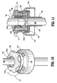
- FIG. 10 is a view similar to the view of FIG. 8 illustrating the manual member of the optical access apparatus in an actuated position securing the endoscope in accordance with the embodiment of FIGS. 1-9;
- FIG. 11 is a view similar to the view of FIG. 9 further illustrating the collet securing the endoscope upon movement of the manual member to the actuated position in accordance with the embodiment of FIGS. 1-10;
- FIG. 12 is a perspective view illustrating an endoscope positioned within the optical access apparatus and accessing body tissue;
- FIG. 13 is a perspective view of an alternate optical access apparatus for use with the system of the present disclosure;
- FIG. 14 is a perspective view with parts separated of the optical access apparatus in accordance with the embodiment of FIG. 13, illustrating components of the access member and the housing;
- FIG. 15 is a perspective view of the collet mounted to the elongate member of the optical access apparatus in accordance with the embodiment of FIGS. 13-14;
- FIG. 16 is a perspective view of the manual member of the optical access apparatus in accordance with the embodiment if FIGS. 13-15, illustrating the camming surfaces of the manual member;
- FIG. 17 is an enlarged perspective view of the optical access apparatus with the endoscope positioned therein in accordance with the embodiment if FIGS. 13-16, illustrating the manual member in an initial condition;
- FIG. 18 is a side cross-sectional view of the optical access apparatus with the endoscope positioned therein in accordance with the embodiment of FIGS. 13-17, illustrating the manual member in an initial position;
- FIG. 19 is an axial cross-section view of the housing of the optical access apparatus in accordance with the embodiment of FIGS. 13-18 further illustrating the manual member in the initial position;
- FIG. 20 is a view similar to the view of FIG. 17 illustrating movement of the manual member to the actuated position in accordance with the embodiment of FIGS. 13-19;
- FIG. 21 is a view similar to the view of FIG. 18 further illustrating movement of the manual member to the actuated position in accordance with the embodiment of FIGS. 13-20; and
- FIG. 22 is a view similar to the view of FIG. 19 further illustrating movement of the manual member to the actuated position in accordance with the embodiment of FIGS. 13-21.
- Referring now to FIG. 1, there is illustrated a surgical system in accordance with the present disclosure.
System 10 includes two components, namely,optical access apparatus 100 andendoscope 200 which is positionable within theaccess apparatus 100.System 10 has particular application in accessing the abdominal cavity during a laparoscopic procedure.Endoscope 200 is positioned withinoptical access apparatus 100 and the assembled unit is advanced through an incision and into the body cavity. During the advancement within tissue,endoscope 200 permits constant visualization of the neighboring tissue thereby providing confirmation upon entering into the body cavity while also preventing undesired contact or engagement with any underlying organs. Alternatively,endoscope 200 may be positioned withinoptical access apparatus 100 after theoptical access apparatus 100 has been advanced into the body cavity. -
Endoscope 200 may be any conventional scope suitable for endoscopic applications including, e.g., a laparoscope, arthroscope, colonoscope, etc. In one preferred embodiment,endoscope 200 may be the scope disclosed in commonly assignedU.S. Patent No. 5,412,504 to Leiner , the entire contents of which disclosure are hereby incorporated by reference.Endoscope 200 incorporates an optical train or lens arrangement which is capable of transmitting an image of an object from the distal or objective lens through the eyepiece or monitor for viewing by the surgeon. Thus, although FIG. 1 shows anendoscope 200 with an eyepiece at its proximal end, theendoscope 200 additionally or alternatively may be connected to a monitor. Further details ofendoscope 200 may be ascertained by reference to the '504 patent. - Referring now to FIGS. 2-4,
optical access apparatus 100 of thesystem 10 will be discussed.Access apparatus 100 includeshousing 102, consisting of several assembled components, andelongate member 104 extending distally from thehousing 102.Access apparatus 100 defines longitudinal axis "a". In one preferred embodiment,housing 102 incorporates the following components: manualmanipulative member 106,collet 108 which is positioned within themanual member 106,skirt 110 andhousing plate 112. As appreciated, these components are assembled together to define a single unit which is subsequently attached to elongate oraccess member 104. -
Manual member 106 is adapted to rotate about the longitudinal axis "a" to secureendoscope 200 in a desired longitudinal position within theaccess apparatus 100. In this regard,manual member 106 defines an outerscalloped surface 114 advantageously dimensioned to be gripped by the surgeon.Manual member 106 hascentral aperture 116 extending therethrough which at least partially receivescollet 108, and a plurality of axially dependingtabs 118 positioned about the longitudinal axis "a" in spaced relation.Tabs 118 are engageable withskirt 110 to mount themanual member 106 to theskirt 110.Manual member 106 also defines a pair of diametrically opposed internalaxial slots 120 adjacentcentral aperture 116.Manual member 106 has internal inclined, e.g., frusto-conical,camming surface 122 at the proximal end of themanual member 106. - Referring still to FIGS. 2-4,
collet 108 includesproximal collar 124 which is separated or divided intocollar sections 124a by partial slots 126. The outer surface ofproximal collar 124 defines inclined orcamming surfaces 128 which are obliquely arranged relative to the longitudinal axis "a" ofapparatus 100. As to be appreciated,collar sections 124a are adapted to be deflected radially inwardly relative to the axis "a" to frictionally engageendoscope 200 through cooperation of camming surfaces 122, 128 ofmanual member 106 andcollet 108, respectively.Collet 108 further defines a pair of diametrically opposed cam pins 130. Cam pins 130 are received withinaxial slots 120 ofmanual member 106 and provide axial movement to collet 108 upon rotation ofmanual member 106. Cam pins 130 are retained withinslots 120 and traverse theslots 120 in a longitudinal direction upon rotational movement ofmanual member 106 andcollet 108. - With reference now to FIGS. 2-5,
skirt 110 includes proximal or upperannular wall 132 and lowerannular wall 134 interconnected by intermediate slopedwall 136.Skirt 110 defines internal shoulder 138 (FIG. 5) extending transversely relative to axis "a".Shoulder 138 is engaged by lockingtabs 118, specifically,transverse shelves 118a of the lockingtabs 118, ofmanual member 106 in the assembled condition of the components to secureskirt 110 andmanual member 106. FIG. 5 illustrates in detail the relationship of lockingtabs 118 andshoulder 138.Skirt 110 further defines a plurality of rectangular shapedopenings 140 extending through slopedwall 136. -
Housing plate 112 includescentral aperture 142 which is general alignment with the longitudinal axis "a" andaxial tabs 144.Tabs 144 possessshelves 144a which are received withinrectangular openings 140 ofskirt 110 to securehousing plate 112 to theskirt 110. FIG. 4 illustrates in detail the relationship oftabs 144 ofhousing plate 112 andrectangular openings 140 ofskirt 110.Housing plate 112 further defines a plurality ofinternal projections 146.Projections 146 assist in securingplate 112 to elongatemember 104 and to prevent rotational movement of theplate 112 relative to theelongate member 104. - Referring still to FIGS. 2-5, elongate or
access member 104 will be discussed.Elongate member 104 includesflange 148 adjacent its proximal end.Flange 148 is generally disc-shaped and defines two opposedradial slots 150.Radial slots 150 accommodateprojections 146 ofplate 112 in the assembled condition of the components to rotationally fix the components. As shown,flange 148 rests onhousing plate 112 when assembled withinhousing 102.Elongate member 104 further defines a pair ofangled cam slots 152 extending completely through the wall ofelongate member 104 proximal offlange 148.Cam slots 152 receivecam pins 130 ofcollet 108 and are dimensioned to permit thepins 130 to traverse theslots 152 upon rotational movement ofmanual member 106 and thecollet 108. As appreciated, during this rotational movement ofcollet 108,collet 108 is driven in a general downward direction relative to elongatemember 104 through the sloped arrangement ofcam slots 152.Elongate member 104 further defines a pair of partial internalangled grooves 154 in its interior surface proximal offlange 146.Grooves 154 facilitate assembly ofcollet 108 withinelongate member 104 by receiving cam pins 130 of thecollet 108 during insertion of thecollet 108 within theelongate member 104. - Referring now to FIGS. 6-7, the distal end portion of
elongate member 104 will be discussed.Elongate member 104 defines penetratingend 156 which is characterized by having an irregularshaped nose 158 with roundedtip 160. In particular,nose 158 is generally tapered in configuration defining a complex curved arrangement. In a first profile ofnose 158 depicted in FIG. 6, thenose 158 includes opposedconcave surfaces 162. In a second profile (rotated 90°) as depicted in FIG. 7,nose 158 definesconvex surfaces 164. This alternating concave and convex arrangement provides a substantially reduced profile (in cross-section) compared to conventional conically shaped obturators thereby providing an enhanced ability to penetrate or pass through tissue layers. Various radii of curvature are contemplated.Rounded tip 160, by its arcuate configuration, minimizes the potential of undesired or unintended piercing of tissue. Alternatively, it is envisioned that roundedtip 160 may be more pointed to also pierce tissue if desired. -
Penetrating end 156 is substantially hollow to receive the distal end ofendoscope 200.Penetrating end 156 is fabricated from a biocompatible transparent material including an optical glass or optical polymeric material and may be either a separate component or integrally formed, e.g., monolithically, withelongate member 104.elongate member 104 may be fabricated from the transparent or opaque material, desirably a biocompatible metal or plastic.Penetrating end 156 is adapted to pass through tissue and may also be capable of cutting or piercing through tissue if desired. - The components of the optical access apparatus may include any suitable biocompatible metal such as stainless steel and titanium and its alloys. Alternatively, the optical access apparatus may include a polymeric material such as polycarbonate, polystyrene, etc.... and manufactured via know molding techniques.
Elongate member 104 may be transparent throughout its entire length. Alternatively, only penetratingend 156 ofelongate member 104 may be transparent. - The use and function of the
system 10 will now be discussed. In laparoscopic surgery, the abdominal cavity is insufflated with a suitable biocompatible gas such as, e.g., CO2 gas, to insufflate the body cavity and lift the body cavity wall away from the internal organs therein. The insufflation may be performed with an insufflation needle or similar device as is conventional in the art. Thereafter, an incision is made in the outer epidermal surface of the abdominal cavity. The incision is preferably small, for example, within a range from 2 to 7 mm, and may be made with a scalpel etc. Thereafter,endoscope 200 ofsystem 10 is positioned withinoptical access apparatus 100 and advanced such that the distal window of theendoscope 200 is adjacent thenose 158 ofelongate member 104. FIGS. 8-9 illustrate the relationship ofendoscope 200 withinoptical access apparatus 10. In FIGS. 8-9,manual member 106 andcollet 108 are in an initialposition permitting endoscope 200 to advance withinelongate member 104. Whenendoscope 200 is at the desired position withinaccess apparatus 100, e.g., when the distal objective of theendoscope 200 is within oradjacent nose 158 ofelongate member 104, theendoscope 200 is then secured at the desired location by manipulating the holding mechanism as discussed below. - With reference now to FIGS. 10-11, to secure
endoscope 200,manual member 106 is rotated in the direction of the directional arrows "Z". Rotation ofmanual member 106 causes corresponding rotation ofcollet 108 through the receptive arrangement of cam pins 130 of thecollet 108 withininternal slots 120 of themanual member 106. Concurrently with the rotation ofcollet 108, cam pins 130traverse cam slots 152 ofelongate member 104, which drivescollet 108 in a distal or downward direction as shown by directional arrows "B". It is noted that cam pins 130 also traverse internal slots 120 (i.e., move in a distal longitudinal direction) ofmanual member 106 to permitcollet 108 to move distally relative tomanual member 106. During distal movement ofcollet 108,camming surface 122 ofmanual member 106 cooperates withcamming surfaces 128 ofcollar sections 124a to cause thecollar sections 124a to flex inwardly and compressively engage theendoscope 200 and frictionally secure theendoscope 200 withinaccess apparatus 100. - With reference to FIG. 12, the assembled
system 10 is then introduced within the small incision "i" by positioningnose 158 ofelongate member 104 within the incision and advancing thesystem 10 through the incision and the underlying tissue structure.Nose 158 is advantageously dimensioned to penetrate and dissect the tissue along its path desirably in a non-traumatic fashion. During advancement ofsystem 10,endoscope 200 is utilized to view the path along which the system is advanced to ensure that any underlying tissue or organ site is prevented from contact with theaccess apparatus 100 and also to confirm entry within the body cavity. Oncesystem 10 is positioned at the desired location relative to the abdominal cavity,endoscope 200 may be used to monitor the desired surgical procedure being performed within the cavity. In the alternative,endoscope 200 may be inserted into and secured in theaccess apparatus 100 after theaccess apparatus 100 has been used to penetrate tissue. - Referring now to FIGS. 13-15, there is illustrated an alternate embodiment of the optical access apparatus for use in the
system 10 of the present disclosure.Optical access apparatus 300 is substantially similar toaccess apparatus 100 of FIGS. 1-12, and possesseshousing 302 andelongate member 304.Housing 302 consists ofmanual member 306,collet 308,skirt 310,flange extension 312 andhousing plate 314 with the components assembled together to define a single unit.Manual member 306 is substantially identical tomanual member 106 ofaccess apparatus 100 but further defmes internal cam shelves 316 (four are shown) as best depicted in FIG. 16, which replaces camming surfaces 122 ofmanual member 106 of theaforedescribed access apparatus 100.Manual member 306 is adapted to rotate about longitudinal axis "a" and relative tocollet 308. In this embodiment,collet 308 is stationary withinhousing 302, i.e., it does not rotate withmanual member 306. - As best depicted in FIGS. 14-15,
collet 308 includesproximal collar 318 having fourcollar sections 318a withadjacent sections 318a separated byslots 320. (In FIG. 15,housing 302 is shown withoutmanual member 306 mounted tocollet 308.) Eachcollar section 318a has opposedouter grooves 322 arranged in a manner such thatrespective grooves 322 ofadjacent collar sections 318a, in effect, define a recess across theadjacent sections 318a. Grooves or recesses 322 accommodatecam shelves 316 ofmanual member 306 when in the initial position ofmanual member 306. Outer cam surfaces 318b are defined betweengrooves 322. As will be appreciated, during rotation ofmanual member 306,cams shelves 316 ofmanual member 306traverse grooves 322 and engage cam surfaces 318b to biascollar sections 318a inwardly into secured engagement withendoscope 200.Collet 318 further includeslower slots 324 in its outer surface which serve to secure thecollet 318 withinhousing 302. - Referring now to FIGS. 17-19, in conjunction with FIGS. 13-14,
skirt 310 andhousing plate 314 are substantially identical to the corresponding counterparts of the embodiment of FIGS. 1-12, and reference is made to the foregoing description for detailed discussion of the structure and function thereof. However, with this embodiment, it is notedhousing plate 314 includes two pairs ofprojections 146.Projections 146 ofhousing plate 314 are received withinlower slots 324 ofcollet 308 so as to secure and prevent rotational movement of thecollet 308. -
Flange extension 312 replaces flange of the embodiment of FIGS. 1-12, and is a separate component attached to elongatemember 304 by mechanical means.Flange extension 312 includesflange plate 326 andflange collar 328 extending from theflange plate 326.Flange collar 328 definescentral aperture 330 to permit passage of theendoscope 200.Flange collar 328 includesinternal shelves 332 which are received within correspondingopenings 334 in the proximal end ofelongate member 304 to fix theflange extension 312 to theelongate member 304. (FIG. 18)Flange plate 326 rests onhousing plate 314 and defines a plurality ofrectangular grooves 336 in its periphery and a plurality ofspacers 338 at the intersection withflange collar 328.Grooves 336 accommodate portions of lockingtabs 340 extending fromhousing plate 314.Spacers 338 serve to aligncollet 308.Flange plate 328 has two pairs ofopposed slots 342 which accommodateprojections 146 ofhousing plate 314. - With reference again to FIGS. 13 -14,
elongate member 304 is substantially identical to elongatemember 104 of the embodiment of FIGS. 1-12, but, incorporates a separatepenetrating end 344. In this regard, penetratingend 344 is attached to elongatemember 304 through conventional means including adhesives, cements, bayonet coupling, or in a preferred embodiment, a snap fit arrangement consisting of a plurality ofinternal projections 346 extending withinelongate member 304, which are received within correspondingly dimensionedopenings 348 ofelongate member 304. Other means for connecting penetrating end are also envisioned.Penetrating end 344 is transparent as discussed hereinabove and is preferably identical in configuration to the penetrating end of the embodiment of FIGS. 1-12. - Referring now to FIGS. 20-22, the function and use of
optical access apparatus 300 will be discussed. The abdominal cavity is insufflated and the incision is formed in the epidermal tissue.Endoscope 200 is positioned withinaccess apparatus 300 and advanced to a portion where the distal end of the endoscope is positioned within penetratingend 344.Manual member 306 is rotated about the longitudinal axis "x" in the direction of the rotational arrow 'm" and relative tocollet 308. During this movement,collet 308 remains stationary whileinternal cam shelves 316 ofmanual member 306traverse grooves 322 ofcollet 308 to engage outer cam surfaces 318b ofcollar sections 318a. This camming action drivescollar sections 318a inwardly to the position depicted in FIGS. 21 and 22. In this position,collar sections 318a securely engage theendoscope 200. Thesystem 10 is then used in similar manner to that described in the embodiment of FIGS. 1-12. Alternatively,endoscope 200 is inserted into theaccess apparatus 300 and secured after the access apparatus has penetrated tissue. - It will be understood that various modifications may be made to the embodiments disclosed herein. Therefore, the above description should not be construed as limiting, but merely as exemplifications of preferred embodiments. Those skilled in the art will envision other modifications within the scope and spirit of the claims appended hereto.
Claims (15)
- An optical access apparatus for receiving an endoscope to permit visualization during passage through tissue, which comprises:an access member dimensioned for insertion through body tissue, the access member defining a longitudinal axis and having a longitudinal opening for receiving an endoscope, the access member having a closed penetrating end adapted to pass through tissue, the closed penetrating end being transparent to permit visualization of tissue with the endoscope;a locking collet coaxially mounted relative to the longitudinal axis of the access member, the locking collet having internal surfaces defining an internal passage to permit passage of the endoscope; anda manual member mounted adjacent the locking collet and operatively engageable therewith, the manual member adapted for rotational movement about the longitudinal axis to reduce an internal dimension of the internal passage of the locking collet to cause the internal surfaces of the locking collet to securely engage the endoscope.
- The optical access apparatus according to claim 1 wherein the manual member defines a central aperture for at least partial reception of the locking collet
- The optical access apparatus according to claim 1 or 2, wherein the locking collet is adapted for rotational movement relative to the longitudinal axis whereby rotational movement of the manual member causes the locking collet to correspondingly rotate.
- The optical access apparatus according to claim 1, 2 or 3, wherein the locking collet is adapted for longitudinal movement relative to the manual member.
- The optical access apparatus according to any one of the preceding claims, wherein the locking collet and the manual member includes corresponding camming surfaces whereby upon longitudinal movement of the locking collet relative to the manual member the camming surfaces cooperate to reduce the internal dimension of the internal passage of the locking collet.
- The optical access apparatus according to claim 5 including cam slot means for effecting longitudinal movement of the locking collet upon rotational movement thereof.
- The optical access apparatus according to any one of the preceding claims, wherein the locking collet is fixed relative to the access member.
- The optical access apparatus according to any one of the preceding claims, wherein the manual member is adapted to rotate about the locking collet.
- The optical access apparatus according to any one of the preceding, calims, wherein the penetrating end defines a tapered configuration having opposed concave surfaces and opposed convex surfaces.
- A surgical system, which comprises:an endoscope; andan optical access apparatus for reception of the endoscope, the optical access apparatus including:a housing defining a longitudinal axis;a locking collet mounted to the housing and coaxially mounted relative to the longitudinal axis, the locking collet having internal surfaces defining an internal passage to permit passage of the endoscope;a manual member coaxially mounted about the locking collet, the manual member adapted for rotational movement about the longitudinal axis to compress the locking collet to reduce an internal dimension of the internal passage of the locking collet to thereby cause the internal surfaces of the locking collet to securely engage the endoscope in frictional engagement therewith; andan elongated access member extending from the housing and having a longitudinal opening for receiving the endoscope, the access member having a closed penetrating end adapted to pass through tissue, the closed penetrating end being transparent to permit visualization of tissue with the endoscope.
- The surgical system according to claim, 10 wherein the locking collet is adapted for rotational and longitudinal movement relative to the longitudinal axis whereby rotational movement of the manual member causes the locking collet to rotate and move in a longitudinal direction.
- The surgical system according to claim 10 or 11, wherein the manual member includes internal compressive surfaces adapted to engage the locking collet during longitudinal movement of the locking collet to reduce the internal dimension of the internal passage of the locking collet.
- The surgical system according to claim 10, 11 or 12, wherein the locking collet is fixed within the housing.
- The surgical system according to any one of claims 10 to 13, wherein the manual member is adapted to rotate about the locking collet.
- The surgical system according to claim 14 wherein the manual member includes internal cam shelves, the internal cam shelves accommodated within outer recesses of locking collet when in an initial position of the manual member whereby upon rotational movement of the manual member to an actuated position the cam shelves traverse the grooves to engage outer cam surfaces of the locking collet.
Priority Applications (1)
| Application Number | Priority Date | Filing Date | Title |
|---|---|---|---|
| EP10180954.9A EP2319435B1 (en) | 2005-04-12 | 2006-03-31 | Optical trocar with scope holding assembly |
Applications Claiming Priority (1)
| Application Number | Priority Date | Filing Date | Title |
|---|---|---|---|
| US11/103,892 US7824327B2 (en) | 2005-04-12 | 2005-04-12 | Optical trocar with scope holding assembly |
Related Child Applications (2)
| Application Number | Title | Priority Date | Filing Date |
|---|---|---|---|
| EP10180954.9A Division EP2319435B1 (en) | 2005-04-12 | 2006-03-31 | Optical trocar with scope holding assembly |
| EP10180954.9 Division-Into | 2010-09-28 |
Publications (3)
| Publication Number | Publication Date |
|---|---|
| EP1712196A2 true EP1712196A2 (en) | 2006-10-18 |
| EP1712196A3 EP1712196A3 (en) | 2007-01-10 |
| EP1712196B1 EP1712196B1 (en) | 2012-10-31 |
Family
ID=36694362
Family Applications (2)
| Application Number | Title | Priority Date | Filing Date |
|---|---|---|---|
| EP10180954.9A Expired - Fee Related EP2319435B1 (en) | 2005-04-12 | 2006-03-31 | Optical trocar with scope holding assembly |
| EP06006907A Expired - Fee Related EP1712196B1 (en) | 2005-04-12 | 2006-03-31 | Optical trocar with scope holding assembly |
Family Applications Before (1)
| Application Number | Title | Priority Date | Filing Date |
|---|---|---|---|
| EP10180954.9A Expired - Fee Related EP2319435B1 (en) | 2005-04-12 | 2006-03-31 | Optical trocar with scope holding assembly |
Country Status (5)
| Country | Link |
|---|---|
| US (3) | US7824327B2 (en) |
| EP (2) | EP2319435B1 (en) |
| JP (2) | JP4968818B2 (en) |
| AU (1) | AU2006201374B2 (en) |
| CA (1) | CA2542225C (en) |
Cited By (7)
| Publication number | Priority date | Publication date | Assignee | Title |
|---|---|---|---|---|
| WO2009010076A1 (en) * | 2007-07-13 | 2009-01-22 | Stryker Trauma Gmbh | Trocar with two convex distal surfaces |
| EP2241276A1 (en) * | 2009-04-13 | 2010-10-20 | Tyco Healthcare Group LP | Bendable veress needle assembly |
| EP2430992A1 (en) * | 2010-09-21 | 2012-03-21 | Tyco Healthcare Group LP | Bladeless obturators and bladeless obturator members |
| GB2492987A (en) * | 2011-07-19 | 2013-01-23 | Surgical Innovations Ltd | Optical trocar assembly |
| US8845670B2 (en) | 2006-12-15 | 2014-09-30 | Covidien Lp | Trocar assembly with obturator design |
| WO2017109447A1 (en) * | 2015-12-23 | 2017-06-29 | Surgical Innovations Limited | Trocar |
| US10463399B2 (en) | 2014-11-06 | 2019-11-05 | Asimion Inc. | Visually assisted entry of a Veress needle with a tapered videoscope for microlaparoscopy |
Families Citing this family (43)
| Publication number | Priority date | Publication date | Assignee | Title |
|---|---|---|---|---|
| JP2009536077A (en) * | 2006-05-05 | 2009-10-08 | アルコン,インコーポレイティド | Fluid coupling system |
| ES2279733B1 (en) * | 2006-11-27 | 2008-08-16 | Rudolf Morgenstern Lopez | DEVICE FOR ELIMINATION OF FABRIC IN ENDOSCOPIC OPERATIONS. |
| EP2732781B1 (en) * | 2007-01-03 | 2015-07-01 | Covidien LP | Access sheath with removable optical penetrating member |
| WO2008088753A2 (en) * | 2007-01-12 | 2008-07-24 | Tyco Healthcare Group Lp | Obturator assembly |
| EP2129413B1 (en) * | 2007-02-28 | 2014-04-30 | Covidien LP | Trocar assembly with obturator and retractable stylet |
| AU2008219732B2 (en) * | 2007-02-28 | 2013-06-27 | Covidien Lp | Surgical optical access apparatus |
| JP2010522585A (en) * | 2007-03-22 | 2010-07-08 | マッケ カーディオバスキュラー エルエルシー | Method and apparatus for observing anatomical structures |
| WO2008115575A1 (en) * | 2007-03-22 | 2008-09-25 | Maquet Cardiovascular Llc | Methods and devices for reducing reflection-illuminated artifacts |
| US8002788B2 (en) | 2007-10-05 | 2011-08-23 | Tyco Healthcare Group Lp | Two-mode bladeless trocar assembly |
| EP2082682A3 (en) * | 2008-01-24 | 2009-12-23 | Karl Storz GmbH & Co. KG | Operating anoscope for transanal endoscopic microsurgery |
| US8911463B2 (en) * | 2008-06-10 | 2014-12-16 | Covidien Lp | Bladed/bladeless obturator for use in a surgical trocar assembly |
| US20110082338A1 (en) * | 2009-10-01 | 2011-04-07 | Tyco Healthcare Group Lp | Port fixation with varying thread pitch |
| US8979883B2 (en) | 2009-12-17 | 2015-03-17 | Covidien Lp | Obturator tip |
| US9226774B2 (en) | 2009-12-17 | 2016-01-05 | Covidien Lp | Visual obturator with tip openings |
| US20110196205A1 (en) * | 2010-02-05 | 2011-08-11 | Tyco Healthcare Group Lp | Surgical portal locking system |
| US20110196206A1 (en) * | 2010-02-05 | 2011-08-11 | Tyco Healthcare Group Lp | Port fixation with varying thread diameter |
| WO2011119736A2 (en) * | 2010-03-23 | 2011-09-29 | University Of Louisville Research Foundation, Inc. | Endoscopic overtube assembly |
| US8523873B2 (en) * | 2010-04-08 | 2013-09-03 | Warsaw Orthopedic, Inc. | Neural-monitoring enabled sleeves for surgical instruments |
| US9101315B2 (en) | 2010-11-11 | 2015-08-11 | Specialty Care, Inc. | Cannula system |
| US8821526B2 (en) | 2010-11-11 | 2014-09-02 | Specialtycare, Inc. | Trocar |
| WO2012074751A1 (en) * | 2010-11-17 | 2012-06-07 | Boston Scientific Scimed, Inc. | Bearing assembly for instrument |
| CN103889349B (en) | 2011-10-18 | 2016-09-07 | 柯惠Lp公司 | Optical ferrule needle system |
| US10912699B2 (en) | 2012-01-10 | 2021-02-09 | Alessio Pigazzi | Method of securing a patient onto an operating table when the patient is in a position such as the trendelenburg position and apparatus therefor including a kit |
| US9186173B2 (en) | 2012-04-27 | 2015-11-17 | Specialty Care, Inc. | Optical obturator system |
| JP6058804B2 (en) * | 2012-09-25 | 2017-01-11 | ボストン サイエンティフィック サイムド,インコーポレイテッドBoston Scientific Scimed,Inc. | Biopsy channel mounting adapter |
| WO2014105661A1 (en) | 2012-12-27 | 2014-07-03 | Covidien Lp | Two-shot molded optical obturator |
| US20140275768A1 (en) * | 2013-03-13 | 2014-09-18 | Covidien Lp | Thoracic Scope With Skirt And Gap |
| US10561302B2 (en) * | 2013-03-15 | 2020-02-18 | DePuy Synthes Products, Inc. | Viewing trocar with integrated prism for use with angled endoscope |
| WO2016044388A1 (en) * | 2014-09-16 | 2016-03-24 | Leiboff Arnold | Wound management method and apparatus |
| US10080488B2 (en) | 2014-12-12 | 2018-09-25 | Medix3d LLC | Cleaning device for cleaning a scope, laparoscope or microscope used in surgery or other medical procedures and a method of using the device during surgical or other medical procedures |
| CN105769113B (en) * | 2014-12-23 | 2017-08-29 | 广州迪克医疗器械有限公司 | Apparatus locking switch and puncture outfit |
| US10117675B2 (en) * | 2015-07-28 | 2018-11-06 | Covidien Lp | Trocar tip protector |
| US10327809B2 (en) | 2016-02-29 | 2019-06-25 | Covidien Lp | Clip collar advanced fixation |
| CN105919656A (en) * | 2016-06-27 | 2016-09-07 | 江苏风和医疗器材有限公司 | Puncture core sharp end, and puncture device and puncture core with puncture core sharp end |
| CN111712174A (en) * | 2018-02-15 | 2020-09-25 | 柯惠Lp公司 | Sheath assembly for rigid endoscope |
| US10722111B2 (en) | 2018-03-13 | 2020-07-28 | Covidien Lp | Optical trocar assembly |
| US10736659B2 (en) | 2018-10-23 | 2020-08-11 | Covidien Lp | Optical trocar assembly |
| EP3685776A1 (en) * | 2019-01-25 | 2020-07-29 | CHU de NICE | Holding systems for medical instruments |
| USD890594S1 (en) * | 2019-01-30 | 2020-07-21 | Jiangsu Ecady Machinery Industry Group Co., Ltd. | Pressure regulating knob |
| WO2020176717A1 (en) | 2019-02-28 | 2020-09-03 | Medix3d LLC | Scope cleaning device configured to be removably connected to a surgical tool |
| US11357542B2 (en) | 2019-06-21 | 2022-06-14 | Covidien Lp | Valve assembly and retainer for surgical access assembly |
| EP4087463A1 (en) * | 2020-01-09 | 2022-11-16 | Boston Scientific Scimed, Inc. | Rotatable medical device |
| CN111658150A (en) * | 2020-06-24 | 2020-09-15 | 哈尔滨思哲睿智能医疗设备有限公司 | Peritoneoscope separates fungus locking interface and laparoscopic surgery robot |
Citations (8)
| Publication number | Priority date | Publication date | Assignee | Title |
|---|---|---|---|---|
| US1882213A (en) * | 1929-12-09 | 1932-10-11 | Edward B Donovan | Trocar |
| EP0426407A2 (en) * | 1989-10-31 | 1991-05-08 | Applied Medical Resources Corporation | Improved apparatus for sealing around members extending therethrough |
| US5380302A (en) * | 1993-02-10 | 1995-01-10 | Unisurge, Inc. | Cannula fixation device with retaining ring having identations |
| US5601559A (en) * | 1988-10-24 | 1997-02-11 | Cook Incorporated | Intraosseous needle |
| US5716369A (en) * | 1994-03-25 | 1998-02-10 | Riza; Erol D. | Apparatus facilitating suturing in laparoscopic surgery |
| US20020072713A1 (en) * | 2000-05-24 | 2002-06-13 | Surgical Innovations Ltd. | Surgical seal |
| WO2003026512A1 (en) * | 2001-09-24 | 2003-04-03 | Applied Medical Resources Corporation | Bladeless obturator |
| US20050065543A1 (en) * | 2001-09-24 | 2005-03-24 | Henry Kahle | Bladeless optical obturator |
Family Cites Families (103)
| Publication number | Priority date | Publication date | Assignee | Title |
|---|---|---|---|---|
| US72713A (en) * | 1867-12-31 | akmstead | ||
| US85543A (en) * | 1869-01-05 | Improvement in log-canting apparatus | ||
| US3652100A (en) * | 1970-07-02 | 1972-03-28 | Houdaille Industries Inc | Collet chuck |
| DE2157911C2 (en) | 1970-12-11 | 1982-02-04 | Marc Edmond Jean van Bruxelles Hoorn | Surgical device for ligating internal structures |
| CH531227A (en) * | 1970-12-11 | 1972-11-30 | Stoll & Co H | Method and device for data transmission on knitting machines, in particular flat knitting machines |
| US3852100A (en) * | 1972-12-26 | 1974-12-03 | Marathon Oil Co | Treatment of porous surfaces of articles of manufacture |
| US3920215A (en) * | 1973-02-09 | 1975-11-18 | Dieter W Knauf | Valve |
| US4254762A (en) * | 1979-10-23 | 1981-03-10 | Inbae Yoon | Safety endoscope system |
| US4327723A (en) * | 1980-05-13 | 1982-05-04 | Arrow International, Inc. | Catheter shield |
| US4601710B1 (en) | 1983-08-24 | 1998-05-05 | United States Surgical Corp | Trocar assembly |
| EP0153190B1 (en) | 1984-02-20 | 1989-05-03 | Olympus Optical Co., Ltd. | Endoscopic ovum picker instruments |
| JPS60179033A (en) * | 1984-02-28 | 1985-09-12 | 雪印乳業株式会社 | Laparoscope |
| JPH0628628B2 (en) * | 1985-05-20 | 1994-04-20 | オリンパス光学工業株式会社 | Endoscope |
| US4700964A (en) * | 1986-07-21 | 1987-10-20 | American Recreation Group | Bicycle pivot assembly |
| US4802487A (en) * | 1987-03-26 | 1989-02-07 | Washington Research Foundation | Endoscopically deliverable ultrasound imaging system |
| US5372138A (en) * | 1988-03-21 | 1994-12-13 | Boston Scientific Corporation | Acousting imaging catheters and the like |
| DE8904025U1 (en) * | 1988-04-07 | 1989-05-24 | Schneider (Europe) Ag, Zuerich, Ch | |
| US4878485A (en) * | 1989-02-03 | 1989-11-07 | Adair Edwin Lloyd | Rigid video endoscope with heat sterilizable sheath |
| US5217441A (en) * | 1989-08-15 | 1993-06-08 | United States Surgical Corporation | Trocar guide tube positioning device |
| US5336206A (en) * | 1989-08-15 | 1994-08-09 | United States Surgical Corporation | Trocar penetration depth indicator and guide tube positioning device |
| US5169397A (en) * | 1990-02-08 | 1992-12-08 | Olympus Optical Co., Ltd. | Medical instrument |
| US5685820A (en) * | 1990-11-06 | 1997-11-11 | Partomed Medizintechnik Gmbh | Instrument for the penetration of body tissue |
| DE4035146A1 (en) * | 1990-11-06 | 1992-05-07 | Riek Siegfried | INSTRUMENT FOR PENETRATING BODY TISSUE |
| US5250068A (en) * | 1990-11-30 | 1993-10-05 | Yakuouji Shinkiyu Chiryouin | Optical transmission type acupuncture needle |
| US5261891A (en) * | 1991-01-15 | 1993-11-16 | Ethicon, Inc. | Trocar |
| US5226690A (en) * | 1991-02-04 | 1993-07-13 | Taylor E. Clark | Wheel for irrigation system |
| JP2981302B2 (en) * | 1991-05-13 | 1999-11-22 | 東洋エンジニアリング株式会社 | Gas separation method |
| US5167636A (en) * | 1991-10-24 | 1992-12-01 | Mectra Labs, Inc. | Cannula sealing mechanism |
| US5226890A (en) | 1991-11-13 | 1993-07-13 | United States Surgical Corporation | Tissue gripping device |
| US5279597A (en) * | 1992-01-13 | 1994-01-18 | Arrow International Investment Corp. | Catheter compression clamp |
| US5290276A (en) * | 1992-02-06 | 1994-03-01 | Sewell Jr Frank | Rotatable laparoscopic puncturing instrument |
| US5540711A (en) * | 1992-06-02 | 1996-07-30 | General Surgical Innovations, Inc. | Apparatus and method for developing an anatomic space for laparoscopic procedures with laparoscopic visualization |
| US5354302A (en) * | 1992-11-06 | 1994-10-11 | Ko Sung Tao | Medical device and method for facilitating intra-tissue visual observation and manipulation of distensible tissues |
| US5385572A (en) * | 1992-11-12 | 1995-01-31 | Beowulf Holdings | Trocar for endoscopic surgery |
| US5562696A (en) | 1992-11-12 | 1996-10-08 | Cordis Innovasive Systems, Inc. | Visualization trocar |
| US5334150A (en) * | 1992-11-17 | 1994-08-02 | Kaali Steven G | Visually directed trocar for laparoscopic surgical procedures and method of using same |
| US5569282A (en) * | 1992-12-04 | 1996-10-29 | Werner; Richard S. | Retractable surgical knife |
| US5338313A (en) * | 1992-12-17 | 1994-08-16 | Thomas J. Fogarty, M.D. | Adjustable valve having a radially compressible sealing body |
| US5391152A (en) * | 1993-03-12 | 1995-02-21 | C. R. Bard, Inc. | Catheter interlock assembly |
| US5364367A (en) * | 1993-04-30 | 1994-11-15 | Minnesota Mining And Manufacturing Company | Cannula anchor |
| US5370640A (en) * | 1993-07-01 | 1994-12-06 | Kolff; Jack | Intracorporeal catheter placement apparatus and method |
| US5496259A (en) * | 1993-09-13 | 1996-03-05 | Welch Allyn, Inc. | Sterile protective sheath and drape for video laparoscope and method of use |
| US5441041A (en) * | 1993-09-13 | 1995-08-15 | United States Surgical Corporation | Optical trocar |
| US5690664A (en) | 1993-09-13 | 1997-11-25 | United States Surgical Corporation | Trocar having movable blade |
| US5467762A (en) * | 1993-09-13 | 1995-11-21 | United States Surgical Corporation | Optical trocar |
| US5412504A (en) | 1993-10-05 | 1995-05-02 | United States Surgical Corporation | Optical system for an endoscope |
| CA2109166C (en) * | 1993-10-25 | 2001-05-29 | Luc Rozon | Portable booster battery |
| US5720761A (en) * | 1993-11-16 | 1998-02-24 | Worldwide Optical Trocar Licensing Corp. | Visually directed trocar and method |
| US5609562A (en) * | 1993-11-16 | 1997-03-11 | Worldwide Optical Trocar Licensing Corporation | Visually directed trocar and method |
| WO1995018642A1 (en) * | 1994-01-07 | 1995-07-13 | Omar Omirana | Adhesive surgical retaining device |
| US5591191A (en) * | 1994-01-26 | 1997-01-07 | Kieturakis; Maciej J. | Surgical instrument and method for helically incising a pathway into the interior of the body |
| US5538509A (en) * | 1994-01-31 | 1996-07-23 | Richard-Allan Medical Industries, Inc. | Trocar assembly |
| US5445142A (en) * | 1994-03-15 | 1995-08-29 | Ethicon Endo-Surgery, Inc. | Surgical trocars having optical tips defining one or more viewing ports |
| CA2149290C (en) * | 1994-05-26 | 2006-07-18 | Carl T. Urban | Optical trocar |
| US5582696A (en) * | 1994-05-31 | 1996-12-10 | Health Craft International, Inc. | Glucose level monitoring apparatus |
| US5658306A (en) * | 1994-07-01 | 1997-08-19 | Archimedes Surgical, Inc. | Method for making additional incisions in laparoscopic surgery |
| US5632717A (en) * | 1994-10-07 | 1997-05-27 | Yoon; Inbae | Penetrating endoscope |
| US5569291A (en) * | 1995-02-01 | 1996-10-29 | Ethicon Endo-Surgery, Inc. | Surgical penetration and dissection instrument |
| US5591192A (en) * | 1995-02-01 | 1997-01-07 | Ethicon Endo-Surgery, Inc. | Surgical penetration instrument including an imaging element |
| US5569292A (en) | 1995-02-01 | 1996-10-29 | Ethicon Endo-Surgery, Inc. | Surgical penetration instrument with transparent blades and tip cover |
| US5738628A (en) * | 1995-03-24 | 1998-04-14 | Ethicon Endo-Surgery, Inc. | Surgical dissector and method for its use |
| US5607441A (en) * | 1995-03-24 | 1997-03-04 | Ethicon Endo-Surgery, Inc. | Surgical dissector |
| US5662673A (en) * | 1995-04-05 | 1997-09-02 | Kieturakis; Maciej J. | Surgical trocar and method for placing a trocar sleeve in a body wall |
| US5980549A (en) * | 1995-07-13 | 1999-11-09 | Origin Medsystems, Inc. | Tissue separation cannula with dissection probe and method |
| ES2129247T3 (en) * | 1995-04-21 | 1999-06-01 | Bard Inc C R | SET OF INTERCONNECTABLE CATHETERS. |
| US5857999A (en) * | 1995-05-05 | 1999-01-12 | Imagyn Medical Technologies, Inc. | Small diameter introducer for laparoscopic instruments |
| US5571133A (en) * | 1995-06-01 | 1996-11-05 | Yoon; Inbae | Penetrating instrument with sequential indication of entry into anatomical cavities |
| US5552238A (en) * | 1995-06-26 | 1996-09-03 | The United States Of America As Represented By The Secretary Of The Air Force | Stabilized rechargeable cell in MSE and method therefor |
| KR0157345B1 (en) * | 1995-06-30 | 1998-12-01 | 김광호 | Electric cell for semiconductor memory |
| US5968065A (en) * | 1995-07-13 | 1999-10-19 | Origin Medsystems, Inc. | Tissue separation cannula |
| US5860995A (en) * | 1995-09-22 | 1999-01-19 | Misener Medical Co. Inc. | Laparoscopic endoscopic surgical instrument |
| US5620456A (en) | 1995-10-20 | 1997-04-15 | Lasersurge, Inc. | Trocar assembly |
| US5620188A (en) * | 1995-11-08 | 1997-04-15 | Ryobi North America | Router collet |
| EP1466564B1 (en) * | 1996-03-22 | 2010-10-20 | Warsaw Orthopedic, Inc. | Devices for percutaneous surgery related applications |
| US5662613A (en) * | 1996-05-14 | 1997-09-02 | Astarita; Denis C. | Endoscopic instrument lock |
| US5681323A (en) | 1996-07-15 | 1997-10-28 | Arick; Daniel S. | Emergency cricothyrotomy tube insertion |
| TW375522B (en) * | 1996-10-24 | 1999-12-01 | Danek Medical Inc | Devices for percutaneous surgery under direct visualization and through an elongated cannula |
| US5843115A (en) * | 1996-10-28 | 1998-12-01 | Morejon; Orlando | Trocar insertion device |
| US6176824B1 (en) * | 1996-10-29 | 2001-01-23 | James M. Davis | Fiberoptically illuminated appliances |
| US5865817A (en) * | 1997-04-29 | 1999-02-02 | Moenning; Stephen P. | Apparatus and method for securing a medical instrument to a cannula of a trocar assembly |
| US5817061A (en) * | 1997-05-16 | 1998-10-06 | Ethicon Endo-Surgery, Inc. | Trocar assembly |
| US5893889A (en) * | 1997-06-20 | 1999-04-13 | Harrington; Michael | Artificial disc |
| US5893689A (en) * | 1997-08-07 | 1999-04-13 | Juhasz; John C | Drill bit adapter |
| US5873889A (en) | 1997-08-08 | 1999-02-23 | Origin Medsystems, Inc. | Tissue separation cannula with dissection probe and method |
| DE19748579C2 (en) * | 1997-11-04 | 2000-02-03 | Storz Karl Gmbh & Co | Endoscopic instrument |
| US6478808B2 (en) * | 1997-12-17 | 2002-11-12 | Closys Corporation | Clotting cascade initiating apparatus and methods of use and methods of closing wounds |
| US6282442B1 (en) * | 1998-09-11 | 2001-08-28 | Surgical Laser Technologies, Inc. | Multi-fit suction irrigation hand piece |
| US20040236347A1 (en) * | 1999-03-12 | 2004-11-25 | Olympus Optical Co., Ltd. | Trocar sheath tube |
| JP2000287915A (en) * | 1999-04-08 | 2000-10-17 | Machida Endscope Co Ltd | Guide tube device for surgery |
| US6209886B1 (en) * | 1999-04-30 | 2001-04-03 | Medtronic, Inc. | Resecting tool with independent variable axial extension for tool implements and guide sleeves |
| US6228059B1 (en) * | 1999-06-16 | 2001-05-08 | Denis C. Astarita | Endoscopic instrument locks |
| US6450992B1 (en) * | 1999-07-02 | 2002-09-17 | Smith & Nephew, Inc. | Cannula interface |
| US6206823B1 (en) * | 1999-08-02 | 2001-03-27 | Ethicon Endo-Surgery, Inc. | Surgical instrument and method for endoscopic tissue dissection |
| US6478606B1 (en) * | 2000-01-11 | 2002-11-12 | Mcnerney Gerald | Twist-on connector with a heat-shrinkable skirt |
| US6336914B1 (en) * | 2000-01-13 | 2002-01-08 | Gillespie, Iii Richard D. | Releasable interlock assembly having axial and rotational engagement |
| WO2002001998A2 (en) * | 2000-05-16 | 2002-01-10 | Taut, Inc. | Penetrating tip for trocar assembly |
| US6719772B2 (en) * | 2001-09-13 | 2004-04-13 | Terumo Medical Corporation | Retaining device for axially restraining movement between tubular elements of a medical device |
| JP2003199755A (en) * | 2001-12-28 | 2003-07-15 | Olympus Optical Co Ltd | Trocar for operation under endoscope |
| JP3743512B2 (en) * | 2002-07-30 | 2006-02-08 | 株式会社八光 | Surgical mantle |
| BR0315636A (en) * | 2002-10-23 | 2005-08-23 | Intellimed Surgical Solutions | Direct View Entry Location Dissector |
| US20060041270A1 (en) * | 2004-05-07 | 2006-02-23 | Jay Lenker | Medical access sheath |
| AU2006223178A1 (en) * | 2005-03-10 | 2006-09-21 | Custom Medical Applications, Inc. | Catheter connection hub |
| US20070135679A1 (en) * | 2005-12-13 | 2007-06-14 | Ethicon Endo-Surgery, Inc. | Colonoscopic device stabilizer |
-
2005
- 2005-04-12 US US11/103,892 patent/US7824327B2/en active Active
-
2006
- 2006-03-31 JP JP2006100848A patent/JP4968818B2/en not_active Expired - Fee Related
- 2006-03-31 EP EP10180954.9A patent/EP2319435B1/en not_active Expired - Fee Related
- 2006-03-31 EP EP06006907A patent/EP1712196B1/en not_active Expired - Fee Related
- 2006-04-03 AU AU2006201374A patent/AU2006201374B2/en not_active Ceased
- 2006-04-06 CA CA2542225A patent/CA2542225C/en not_active Expired - Fee Related
-
2010
- 2010-09-15 US US12/882,581 patent/US8517918B2/en active Active
-
2011
- 2011-07-21 JP JP2011159975A patent/JP2011245324A/en not_active Withdrawn
-
2013
- 2013-07-31 US US13/955,469 patent/US10159402B2/en active Active
Patent Citations (8)
| Publication number | Priority date | Publication date | Assignee | Title |
|---|---|---|---|---|
| US1882213A (en) * | 1929-12-09 | 1932-10-11 | Edward B Donovan | Trocar |
| US5601559A (en) * | 1988-10-24 | 1997-02-11 | Cook Incorporated | Intraosseous needle |
| EP0426407A2 (en) * | 1989-10-31 | 1991-05-08 | Applied Medical Resources Corporation | Improved apparatus for sealing around members extending therethrough |
| US5380302A (en) * | 1993-02-10 | 1995-01-10 | Unisurge, Inc. | Cannula fixation device with retaining ring having identations |
| US5716369A (en) * | 1994-03-25 | 1998-02-10 | Riza; Erol D. | Apparatus facilitating suturing in laparoscopic surgery |
| US20020072713A1 (en) * | 2000-05-24 | 2002-06-13 | Surgical Innovations Ltd. | Surgical seal |
| WO2003026512A1 (en) * | 2001-09-24 | 2003-04-03 | Applied Medical Resources Corporation | Bladeless obturator |
| US20050065543A1 (en) * | 2001-09-24 | 2005-03-24 | Henry Kahle | Bladeless optical obturator |
Cited By (12)
| Publication number | Priority date | Publication date | Assignee | Title |
|---|---|---|---|---|
| US8845670B2 (en) | 2006-12-15 | 2014-09-30 | Covidien Lp | Trocar assembly with obturator design |
| WO2009010076A1 (en) * | 2007-07-13 | 2009-01-22 | Stryker Trauma Gmbh | Trocar with two convex distal surfaces |
| EP2241276A1 (en) * | 2009-04-13 | 2010-10-20 | Tyco Healthcare Group LP | Bendable veress needle assembly |
| EP2430992A1 (en) * | 2010-09-21 | 2012-03-21 | Tyco Healthcare Group LP | Bladeless obturators and bladeless obturator members |
| US8961552B2 (en) | 2010-09-21 | 2015-02-24 | Covidien Lp | Bladeless obturators and bladeless obturator members |
| US10092321B2 (en) | 2010-09-21 | 2018-10-09 | Covidien Lp | Bladeless obturators and bladeless obturator members |
| GB2492987A (en) * | 2011-07-19 | 2013-01-23 | Surgical Innovations Ltd | Optical trocar assembly |
| WO2013011271A1 (en) | 2011-07-19 | 2013-01-24 | Surgical Innovations Limited | Optical trocar assembly and system |
| US10463399B2 (en) | 2014-11-06 | 2019-11-05 | Asimion Inc. | Visually assisted entry of a Veress needle with a tapered videoscope for microlaparoscopy |
| US11602374B1 (en) | 2014-11-06 | 2023-03-14 | Enable, Inc. | Visually assisted entry of a fluid delivering needle with a tapered videoscope |
| WO2017109447A1 (en) * | 2015-12-23 | 2017-06-29 | Surgical Innovations Limited | Trocar |
| GB2559084A (en) * | 2015-12-23 | 2018-07-25 | Surgical Innovations Ltd | Trocar |
Also Published As
| Publication number | Publication date |
|---|---|
| CA2542225A1 (en) | 2006-10-12 |
| US20130317298A1 (en) | 2013-11-28 |
| US10159402B2 (en) | 2018-12-25 |
| JP2011245324A (en) | 2011-12-08 |
| US20060226655A1 (en) | 2006-10-12 |
| CA2542225C (en) | 2014-10-28 |
| US20110004061A1 (en) | 2011-01-06 |
| EP2319435A3 (en) | 2012-01-11 |
| EP2319435B1 (en) | 2019-12-18 |
| EP2319435A2 (en) | 2011-05-11 |
| US7824327B2 (en) | 2010-11-02 |
| JP4968818B2 (en) | 2012-07-04 |
| EP1712196B1 (en) | 2012-10-31 |
| JP2006289083A (en) | 2006-10-26 |
| AU2006201374A1 (en) | 2006-10-26 |
| AU2006201374B2 (en) | 2011-02-24 |
| US8517918B2 (en) | 2013-08-27 |
| EP1712196A3 (en) | 2007-01-10 |
Similar Documents
| Publication | Publication Date | Title |
|---|---|---|
| EP2319435B1 (en) | Optical trocar with scope holding assembly | |
| US11529169B2 (en) | Optical trocar visualization system and apparatus | |
| US8267952B2 (en) | Bladeless optical obturator | |
| US8202290B2 (en) | Visual obturator with handle | |
| US9226774B2 (en) | Visual obturator with tip openings | |
| AU2008205628B2 (en) | Obturator assembly |
Legal Events
| Date | Code | Title | Description |
|---|---|---|---|
| PUAI | Public reference made under article 153(3) epc to a published international application that has entered the european phase |
Free format text: ORIGINAL CODE: 0009012 |
|
| AK | Designated contracting states |
Kind code of ref document: A2 Designated state(s): AT BE BG CH CY CZ DE DK EE ES FI FR GB GR HU IE IS IT LI LT LU LV MC NL PL PT RO SE SI SK TR |
|
| AX | Request for extension of the european patent |
Extension state: AL BA HR MK YU |
|
| PUAL | Search report despatched |
Free format text: ORIGINAL CODE: 0009013 |
|
| AK | Designated contracting states |
Kind code of ref document: A3 Designated state(s): AT BE BG CH CY CZ DE DK EE ES FI FR GB GR HU IE IS IT LI LT LU LV MC NL PL PT RO SE SI SK TR |
|
| AX | Request for extension of the european patent |
Extension state: AL BA HR MK YU |
|
| 17P | Request for examination filed |
Effective date: 20070614 |
|
| AKX | Designation fees paid |
Designated state(s): DE ES FR GB IE IT |
|
| 17Q | First examination report despatched |
Effective date: 20070822 |
|
| GRAP | Despatch of communication of intention to grant a patent |
Free format text: ORIGINAL CODE: EPIDOSNIGR1 |
|
| RAP1 | Party data changed (applicant data changed or rights of an application transferred) |
Owner name: TYCO HEALTHCARE GROUP LP |
|
| GRAS | Grant fee paid |
Free format text: ORIGINAL CODE: EPIDOSNIGR3 |
|
| GRAA | (expected) grant |
Free format text: ORIGINAL CODE: 0009210 |
|
| AK | Designated contracting states |
Kind code of ref document: B1 Designated state(s): DE ES FR GB IE IT |
|
| REG | Reference to a national code |
Ref country code: GB Ref legal event code: FG4D |
|
| REG | Reference to a national code |
Ref country code: IE Ref legal event code: FG4D |
|
| RAP2 | Party data changed (patent owner data changed or rights of a patent transferred) |
Owner name: COVIDIEN LP |
|
| REG | Reference to a national code |
Ref country code: DE Ref legal event code: R096 Ref document number: 602006032736 Country of ref document: DE Effective date: 20121227 |
|
| PG25 | Lapsed in a contracting state [announced via postgrant information from national office to epo] |
Ref country code: ES Free format text: LAPSE BECAUSE OF FAILURE TO SUBMIT A TRANSLATION OF THE DESCRIPTION OR TO PAY THE FEE WITHIN THE PRESCRIBED TIME-LIMIT Effective date: 20130211 |
|
| PG25 | Lapsed in a contracting state [announced via postgrant information from national office to epo] |
Ref country code: IT Free format text: LAPSE BECAUSE OF FAILURE TO SUBMIT A TRANSLATION OF THE DESCRIPTION OR TO PAY THE FEE WITHIN THE PRESCRIBED TIME-LIMIT Effective date: 20121031 |
|
| PLBE | No opposition filed within time limit |
Free format text: ORIGINAL CODE: 0009261 |
|
| STAA | Information on the status of an ep patent application or granted ep patent |
Free format text: STATUS: NO OPPOSITION FILED WITHIN TIME LIMIT |
|
| 26N | No opposition filed |
Effective date: 20130801 |
|
| REG | Reference to a national code |
Ref country code: DE Ref legal event code: R097 Ref document number: 602006032736 Country of ref document: DE Effective date: 20130801 |
|
| REG | Reference to a national code |
Ref country code: FR Ref legal event code: PLFP Year of fee payment: 11 |
|
| REG | Reference to a national code |
Ref country code: FR Ref legal event code: PLFP Year of fee payment: 12 |
|
| REG | Reference to a national code |
Ref country code: FR Ref legal event code: PLFP Year of fee payment: 13 |
|
| PGFP | Annual fee paid to national office [announced via postgrant information from national office to epo] |
Ref country code: DE Payment date: 20210217 Year of fee payment: 16 Ref country code: GB Payment date: 20210219 Year of fee payment: 16 |
|
| PGFP | Annual fee paid to national office [announced via postgrant information from national office to epo] |
Ref country code: IE Payment date: 20220218 Year of fee payment: 17 |
|
| PGFP | Annual fee paid to national office [announced via postgrant information from national office to epo] |
Ref country code: FR Payment date: 20220221 Year of fee payment: 17 |
|
| REG | Reference to a national code |
Ref country code: DE Ref legal event code: R119 Ref document number: 602006032736 Country of ref document: DE |
|
| GBPC | Gb: european patent ceased through non-payment of renewal fee |
Effective date: 20220331 |
|
| PG25 | Lapsed in a contracting state [announced via postgrant information from national office to epo] |
Ref country code: GB Free format text: LAPSE BECAUSE OF NON-PAYMENT OF DUE FEES Effective date: 20220331 Ref country code: DE Free format text: LAPSE BECAUSE OF NON-PAYMENT OF DUE FEES Effective date: 20221001 |
|
| REG | Reference to a national code |
Ref country code: IE Ref legal event code: MM4A |
|
| PG25 | Lapsed in a contracting state [announced via postgrant information from national office to epo] |
Ref country code: IE Free format text: LAPSE BECAUSE OF NON-PAYMENT OF DUE FEES Effective date: 20230331 Ref country code: FR Free format text: LAPSE BECAUSE OF NON-PAYMENT OF DUE FEES Effective date: 20230331 |