EP1713115B1 - Exposure apparatus, exposure method, and device producing method - Google Patents
Exposure apparatus, exposure method, and device producing method Download PDFInfo
- Publication number
- EP1713115B1 EP1713115B1 EP05710042.2A EP05710042A EP1713115B1 EP 1713115 B1 EP1713115 B1 EP 1713115B1 EP 05710042 A EP05710042 A EP 05710042A EP 1713115 B1 EP1713115 B1 EP 1713115B1
- Authority
- EP
- European Patent Office
- Prior art keywords
- substrate
- temperature
- liquid
- exposure
- temperature adjustment
- Prior art date
- Legal status (The legal status is an assumption and is not a legal conclusion. Google has not performed a legal analysis and makes no representation as to the accuracy of the status listed.)
- Not-in-force
Links
Images


Classifications
-
- H—ELECTRICITY
- H01—ELECTRIC ELEMENTS
- H01L—SEMICONDUCTOR DEVICES NOT COVERED BY CLASS H10
- H01L21/00—Processes or apparatus adapted for the manufacture or treatment of semiconductor or solid state devices or of parts thereof
- H01L21/02—Manufacture or treatment of semiconductor devices or of parts thereof
- H01L21/027—Making masks on semiconductor bodies for further photolithographic processing not provided for in group H01L21/18 or H01L21/34
- H01L21/0271—Making masks on semiconductor bodies for further photolithographic processing not provided for in group H01L21/18 or H01L21/34 comprising organic layers
- H01L21/0273—Making masks on semiconductor bodies for further photolithographic processing not provided for in group H01L21/18 or H01L21/34 comprising organic layers characterised by the treatment of photoresist layers
- H01L21/0274—Photolithographic processes
-
- G—PHYSICS
- G03—PHOTOGRAPHY; CINEMATOGRAPHY; ANALOGOUS TECHNIQUES USING WAVES OTHER THAN OPTICAL WAVES; ELECTROGRAPHY; HOLOGRAPHY
- G03F—PHOTOMECHANICAL PRODUCTION OF TEXTURED OR PATTERNED SURFACES, e.g. FOR PRINTING, FOR PROCESSING OF SEMICONDUCTOR DEVICES; MATERIALS THEREFOR; ORIGINALS THEREFOR; APPARATUS SPECIALLY ADAPTED THEREFOR
- G03F7/00—Photomechanical, e.g. photolithographic, production of textured or patterned surfaces, e.g. printing surfaces; Materials therefor, e.g. comprising photoresists; Apparatus specially adapted therefor
- G03F7/70—Microphotolithographic exposure; Apparatus therefor
- G03F7/708—Construction of apparatus, e.g. environment aspects, hygiene aspects or materials
- G03F7/70858—Environment aspects, e.g. pressure of beam-path gas, temperature
- G03F7/70866—Environment aspects, e.g. pressure of beam-path gas, temperature of mask or workpiece
- G03F7/70875—Temperature, e.g. temperature control of masks or workpieces via control of stage temperature
-
- G—PHYSICS
- G03—PHOTOGRAPHY; CINEMATOGRAPHY; ANALOGOUS TECHNIQUES USING WAVES OTHER THAN OPTICAL WAVES; ELECTROGRAPHY; HOLOGRAPHY
- G03F—PHOTOMECHANICAL PRODUCTION OF TEXTURED OR PATTERNED SURFACES, e.g. FOR PRINTING, FOR PROCESSING OF SEMICONDUCTOR DEVICES; MATERIALS THEREFOR; ORIGINALS THEREFOR; APPARATUS SPECIALLY ADAPTED THEREFOR
- G03F7/00—Photomechanical, e.g. photolithographic, production of textured or patterned surfaces, e.g. printing surfaces; Materials therefor, e.g. comprising photoresists; Apparatus specially adapted therefor
- G03F7/20—Exposure; Apparatus therefor
- G03F7/2041—Exposure; Apparatus therefor in the presence of a fluid, e.g. immersion; using fluid cooling means
-
- G—PHYSICS
- G03—PHOTOGRAPHY; CINEMATOGRAPHY; ANALOGOUS TECHNIQUES USING WAVES OTHER THAN OPTICAL WAVES; ELECTROGRAPHY; HOLOGRAPHY
- G03F—PHOTOMECHANICAL PRODUCTION OF TEXTURED OR PATTERNED SURFACES, e.g. FOR PRINTING, FOR PROCESSING OF SEMICONDUCTOR DEVICES; MATERIALS THEREFOR; ORIGINALS THEREFOR; APPARATUS SPECIALLY ADAPTED THEREFOR
- G03F7/00—Photomechanical, e.g. photolithographic, production of textured or patterned surfaces, e.g. printing surfaces; Materials therefor, e.g. comprising photoresists; Apparatus specially adapted therefor
- G03F7/70—Microphotolithographic exposure; Apparatus therefor
- G03F7/70216—Mask projection systems
- G03F7/70341—Details of immersion lithography aspects, e.g. exposure media or control of immersion liquid supply
-
- G—PHYSICS
- G03—PHOTOGRAPHY; CINEMATOGRAPHY; ANALOGOUS TECHNIQUES USING WAVES OTHER THAN OPTICAL WAVES; ELECTROGRAPHY; HOLOGRAPHY
- G03F—PHOTOMECHANICAL PRODUCTION OF TEXTURED OR PATTERNED SURFACES, e.g. FOR PRINTING, FOR PROCESSING OF SEMICONDUCTOR DEVICES; MATERIALS THEREFOR; ORIGINALS THEREFOR; APPARATUS SPECIALLY ADAPTED THEREFOR
- G03F7/00—Photomechanical, e.g. photolithographic, production of textured or patterned surfaces, e.g. printing surfaces; Materials therefor, e.g. comprising photoresists; Apparatus specially adapted therefor
- G03F7/70—Microphotolithographic exposure; Apparatus therefor
- G03F7/70691—Handling of masks or workpieces
- G03F7/70716—Stages
-
- G—PHYSICS
- G03—PHOTOGRAPHY; CINEMATOGRAPHY; ANALOGOUS TECHNIQUES USING WAVES OTHER THAN OPTICAL WAVES; ELECTROGRAPHY; HOLOGRAPHY
- G03F—PHOTOMECHANICAL PRODUCTION OF TEXTURED OR PATTERNED SURFACES, e.g. FOR PRINTING, FOR PROCESSING OF SEMICONDUCTOR DEVICES; MATERIALS THEREFOR; ORIGINALS THEREFOR; APPARATUS SPECIALLY ADAPTED THEREFOR
- G03F7/00—Photomechanical, e.g. photolithographic, production of textured or patterned surfaces, e.g. printing surfaces; Materials therefor, e.g. comprising photoresists; Apparatus specially adapted therefor
- G03F7/70—Microphotolithographic exposure; Apparatus therefor
- G03F7/70691—Handling of masks or workpieces
- G03F7/70733—Handling masks and workpieces, e.g. exchange of workpiece or mask, transport of workpiece or mask
- G03F7/7075—Handling workpieces outside exposure position, e.g. SMIF box
-
- G—PHYSICS
- G03—PHOTOGRAPHY; CINEMATOGRAPHY; ANALOGOUS TECHNIQUES USING WAVES OTHER THAN OPTICAL WAVES; ELECTROGRAPHY; HOLOGRAPHY
- G03F—PHOTOMECHANICAL PRODUCTION OF TEXTURED OR PATTERNED SURFACES, e.g. FOR PRINTING, FOR PROCESSING OF SEMICONDUCTOR DEVICES; MATERIALS THEREFOR; ORIGINALS THEREFOR; APPARATUS SPECIALLY ADAPTED THEREFOR
- G03F7/00—Photomechanical, e.g. photolithographic, production of textured or patterned surfaces, e.g. printing surfaces; Materials therefor, e.g. comprising photoresists; Apparatus specially adapted therefor
- G03F7/70—Microphotolithographic exposure; Apparatus therefor
- G03F7/708—Construction of apparatus, e.g. environment aspects, hygiene aspects or materials
- G03F7/70858—Environment aspects, e.g. pressure of beam-path gas, temperature
- G03F7/70883—Environment aspects, e.g. pressure of beam-path gas, temperature of optical system
- G03F7/70891—Temperature
Landscapes
- Physics & Mathematics (AREA)
- General Physics & Mathematics (AREA)
- Health & Medical Sciences (AREA)
- Engineering & Computer Science (AREA)
- Life Sciences & Earth Sciences (AREA)
- Atmospheric Sciences (AREA)
- Toxicology (AREA)
- Environmental & Geological Engineering (AREA)
- Epidemiology (AREA)
- Public Health (AREA)
- Exposure And Positioning Against Photoresist Photosensitive Materials (AREA)
- Condensed Matter Physics & Semiconductors (AREA)
- Manufacturing & Machinery (AREA)
- Computer Hardware Design (AREA)
- Microelectronics & Electronic Packaging (AREA)
- Power Engineering (AREA)
- Exposure Of Semiconductors, Excluding Electron Or Ion Beam Exposure (AREA)
- Container, Conveyance, Adherence, Positioning, Of Wafer (AREA)
- Length Measuring Devices By Optical Means (AREA)
- Microscoopes, Condenser (AREA)
Description
- The present invention relates to an exposure apparatus and an exposure method for exposing a substrate by radiating an exposure light beam onto the substrate through a liquid, and a method for producing a device based on the use of the exposure apparatus and the exposure method.
- Semiconductor devices and liquid crystal display devices are produced by means of the so-called photolithography technique in which a pattern formed on a mask is transferred onto a photosensitive substrate. The exposure apparatus, which is used in the photolithography step, includes a mask stage for supporting the mask and a substrate stage for supporting the substrate. The pattern on the mask is transferred onto the substrate via a projection optical system while successively moving the mask stage and the substrate stage. In recent years, it is demanded to realize the higher resolution of the projection optical system in order to respond to the further advance of the higher integration of the device pattern. As the exposure wavelength to be used is shorter, the resolution of the projection optical system becomes higher. As the numerical aperture of the projection optical system is larger, the resolution of the projection optical system becomes higher. Therefore, the exposure wavelength, which is used for the exposure apparatus, is shortened year by year, and the numerical aperture of the projection optical system is increased as well. The exposure wavelength, which is dominantly used at present, is 248 nm of the KrF excimer laser. However, the exposure wavelength of 193 nm of the ArF excimer laser, which is shorter than the above, is also practically used in some situations. When the exposure is performed, the depth of focus (DOF) is also important in the same manner as the resolution. The resolution R and the depth of focus δ are represented by the following expressions respectively.


- In the expressions, λ represents the exposure wavelength, NA represents the numerical aperture of the projection optical system, and k1 and k2 represent the process coefficients. According to the expressions (1) and (2), the following fact is appreciated. That is, when the exposure wavelength λ is shortened and the numerical aperture NA is increased in order to enhance the resolution R, then the depth of focus δ is narrowed.
- If the depth of focus δ is too narrowed, it is difficult to match the substrate surface with respect to the image plane of the projection optical system. It is feared that the focus margin is insufficient during the exposure operation. Accordingly, the liquid immersion method has been suggested, which is disclosed, for example, in International Publication No.
99/49504 - In relation to the liquid immersion exposure apparatus, the following arrangement is conceived. That is, for example, when the position information about the substrate is measured, a detecting light beam is radiated onto the liquid, and the measurement is performed on the basis of the detecting light beam through the liquid. In such a situation, if the refractive index of the liquid is changed, for example, due to any temperature change, the measurement accuracy is deteriorated, for example, due to any fluctuation of the optical path for the detecting light beam. Similarly, if the refractive index of the liquid is changed, for example, due to any temperature change, the exposure accuracy is deteriorated, for example, due to any fluctuation of the image characteristic (state of formation of the image) to be obtained through the liquid.
- An exposure apparatus according to the preamble of
claim 1 has been disclosed inUS 4 346 164 A . - Similar apparatus are described in
EP 1 498 781 AWO 2005/071491 A andEP 1 624 481 A - The present invention has been made taking the foregoing circumstances into consideration, an object of which is to provide an exposure apparatus, an exposure method, and a method for producing a device, in which the exposure process and the measurement process can be performed satisfactorily through the liquid.
- In order to achieve the object as described above, the present invention adopts the following constructions corresponding to
Figs. 1 to 16 as illustrated in embodiments. However, parenthesized reference numerals affixed to respective elements merely exemplify the elements, with which it is not intended to limit the respective elements. - According to a first aspect of the present invention, there is provided an exposure apparatus (EX) as specified in
claim 1. - According to the present invention, the substrate, which is held by the substrate-holding member, can be adjusted to have a desired temperature by performing the temperature adjustment by using the temperature adjustment system for the substrate-holding member which holds the substrate. Therefore, the temperature change is suppressed for the liquid which makes contact with the substrate, and it is possible to maintain the liquid to be in a desired temperature state. Therefore, for example, even when the exposure apparatus is constructed such that the detecting light beam is radiated onto the liquid to perform the measurement process on the basis of the detecting light beam through the liquid, it is possible to maintain the satisfactory measurement accuracy. Further, it is possible to maintain the satisfactory exposure accuracy, because the exposure light beam can be radiated onto the substrate through the liquid which is in the desired temperature state.
- According to the present invention, there is provided a method for producing a device, comprising using the exposure apparatus (EX) according to any one of the aspects described above. According to the present invention, the device, which exhibits the desired performance, can be produced by using the exposure apparatus which is capable of satisfactorily performing the exposure process and the measurement process through the liquid.
- According to a second aspect of the present invention, there is provided an exposure method as specified in claim 25.
- According to the present invention, it is possible to avoid the occurrence of the temperature distribution and the change of the temperature of the liquid with respect to the desired temperature when the substrate and the liquid make contact with each other, by adjusting the temperature of the substrate in consideration of the temperature of the liquid. Therefore, for example, the liquid, which is in contact with the substrate, can be also maintained at the desired temperature. Therefore, even when the exposure apparatus is constructed such that the detecting light beam is radiated onto the liquid to perform the measurement process on the basis of the detecting light beam through the liquid, it is possible to maintain the satisfactory measurement accuracy. Further, it is possible to maintain the satisfactory exposure accuracy, because the exposure light beam can be radiated onto the substrate through the liquid which is in the desired temperature state. Further, it is also possible to avoid the thermal deformation and the temperature change of the substrate when the substrate makes contact with the liquid. The exposure can be performed highly accurately while maintaining the satisfactory positional adjustment accuracy and the satisfactory overlay accuracy.
- According to the present invention, there is provided a method for producing a device, comprising using the exposure apparatus or method as described above. According to the present invention, it is possible to produce the device which exhibits the desired performance, in accordance with the exposure method which makes it possible to satisfactorily perform the exposure process and the measurement process through the liquid.
-
-
Fig. 1 shows a schematic arrangement illustrating an embodiment of an exposure apparatus of the present invention. -
Fig. 2 shows a magnified side view illustrating main parts to depict a substrate stage and a temperature adjustment system. -
Fig. 3 shows a plan view illustrating the substrate stage as viewed from an upper position. -
Figs. 4(a) and 4(b) show the temperature adjustment system which performs temperature adjustment for a measuring member. -
Fig. 5 shows the temperature adjustment system which performs temperature adjustment for an optical element through which an exposure light beam passes. -
Fig. 6 shows a flow chart illustrating an exemplary exposure method according to the present invention. -
Fig. 7 shows the temperature adjustment system which performs temperature adjustment for a substrate before being loaded on a substrate holder. -
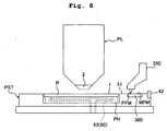
Fig. 8 illustrates the measuring operation of a mark-detecting system. -
Fig. 9 illustrates the measuring operation of the mark-detecting system. -
Fig. 10 shows another embodiment of a temperature adjustment system according to the present invention. -
Fig. 11 shows still another embodiment of a temperature adjustment system according to the present invention. -
Fig. 12 shows still another embodiment of a temperature adjustment system according to the present invention. -
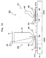
Figs. 13(a) and 13(b) schematically illustrate the situation of the temperature change of the liquid supplied from the liquid supply mechanism. -
Fig. 14 shows a member for attenuating the temperature variation of the liquid. -
Fig. 15 shows a schematic arrangement illustrating an embodiment of an exposure apparatus of the present invention. -
Fig. 16 shows a flow chart illustrating exemplary steps of producing a semiconductor device. - The exposure apparatus according to the present invention will be explained below with reference to the drawings. However, the present invention is not limited thereto.
-
Fig. 1 shows a schematic arrangement illustrating an embodiment of an exposure apparatus of the present invention. With reference toFig. 1 , the exposure apparatus EX includes a mask stage MST which is movable while supporting a mask M, a substrate stage PST which has a substrate holder PH for holding a substrate P and which is movable while supporting the substrate P, an illumination optical system IL which illuminates, with an exposure light beam EL, the mask M supported by the mask stage MST, a projection optical system PL which performs the projection exposure for the substrate P supported by the substrate stage PST with an image of a pattern of the mask M illuminated with the exposure light beam EL, atemperature adjustment system 60 which performs temperature adjustment for the substrate holder PH, and a control unit CONT which integrally controls the operation of the entire exposure apparatus EX. - The exposure apparatus EX of this embodiment is a liquid immersion exposure apparatus to which the liquid immersion method is applied in order that the exposure wavelength is substantially shortened to improve the resolution and the depth of focus is substantially widened. The exposure apparatus EX includes a
liquid supply mechanism 10 which supplies the liquid LQ onto the substrate P, and aliquid recovery mechanism 20 which recovers the liquid LQ from the substrate P. In this embodiment, pure water is used for the liquid LQ. The exposure apparatus EX forms a liquid immersion area AR2 locally on at least a part of the substrate P including a projection area AR1 of the projection optical system PL by the liquid LQ supplied from theliquid supply mechanism 10 at least during the period in which the image of the pattern of the mask M is transferred onto the substrate P, the liquid immersion area AR2 being larger than the projection area AR1 and smaller than the substrate P. Specifically, the exposure apparatus EX is operated as follows. That is, the space between the surface (exposure surface) of the substrate P and theoptical element 2 disposed at the end portion on the image plane side of the projection optical system PL is filled with the liquid LQ. The image of the pattern of the mask M is projected onto the substrate P to expose the substrate P therewith via the projection optical system PL and the liquid LQ disposed between the projection optical system PL and the substrate P. - The embodiment of the present invention will be explained as exemplified by a case using the scanning type exposure apparatus (so-called scanning stepper) as the exposure apparatus EX in which the substrate P is exposed with the pattern formed on the mask M while synchronously moving the mask M and the substrate P in mutually different directions (opposite directions) in the scanning directions (predetermined directions). In the following explanation, the X axis direction is the synchronous movement direction (scanning direction, predetermined direction) for the mask M and the substrate P in the horizontal plane, the Y axis direction (non-scanning direction) is the direction which is perpendicular to the X axis direction in the horizontal plane, and the Z axis direction is the direction which is perpendicular to the X axis direction and the Y axis direction and which is coincident with the optical axis AX of the projection optical system PL. The directions of rotation (inclination) about the X axis, the Y axis, and the Z axis are designated as θX, θY, and θZ directions respectively. The term "substrate" referred to herein includes those obtained by coating a semiconductor wafer surface with a resist, and the term "mask" includes a reticle formed with a device pattern to be subjected to the reduction projection onto the substrate.
- The illumination optical system IL is provided so that the mask M, which is supported on the mask stage MST, is illuminated with the exposure light beam EL. The illumination optical system IL includes, for example, an exposure light source, an optical integrator which uniformizes the illuminance of the light flux radiated from the exposure light source, a condenser lens which collects the exposure light beam EL emitted from the optical integrator, a relay lens system, and a variable field diaphragm which sets the illumination area on the mask M illuminated with the exposure light beam EL to be slit-shaped. The predetermined illumination area on the mask M is illuminated with the exposure light beam EL having a uniform illuminance distribution by the illumination optical system IL. Those usable as the exposure light beam EL radiated from the illumination optical system IL include, for example, emission lines (g-ray, h-ray, i-ray) radiated, for example, from a mercury lamp, far ultraviolet light beams (DUV light beams) such as the KrF excimer laser beam (wavelength: 248 nm), and vacuum ultraviolet light beams (VUV light beams) such as the ArF excimer laser beam (wavelength: 193 nm) and the F2 laser beam (wavelength: 157 nm). In this embodiment, the ArF excimer laser beam is used. As described above, the liquid LQ is pure water in this embodiment, through which even the ArF excimer laser beam as the exposure light beam EL is transmissive. Those also capable of being transmitted through pure water include the emission line (g-ray, h-ray, i-ray) and the far ultraviolet light beam (DUV light beam) such as the KrF excimer laser beam (wavelength: 248 nm).
- The mask stage MST is movable while holding the mask M. The mask stage MST is two-dimensionally movable in the plane perpendicular to the optical axis AX of the projection optical system PL, i.e., in the XY plane, and it is finely rotatable in the θZ direction. The mask stage MST is driven by a mask stage-driving unit MSTD such as a linear motor. The mask stage-driving unit MSTD is controlled by the control unit CONT. A
movement mirror 40, which is movable together with the mask stage MST, is provided on the mask stage MST. Alaser interferometer 41 is provided at a position opposed to themovement mirror 40. The position in the two-dimensional direction and the angle of rotation of the mask M on the mask stage MST are measured in real-time by thelaser interferometer 41. The result of the measurement is outputted to the control unit CONT. The control unit CONT drives the mask stage-driving unit MSTD on the basis of the result of the measurement obtained by thelaser interferometer 41 to thereby position the mask M supported on the mask stage MST. - The projection optical system PL projects the pattern on the mask M onto the substrate P at a predetermined projection magnification β to perform the exposure. The projection optical system PL includes a plurality of optical elements including an optical element (lens) 2 provided at the end portion on the side of the substrate P. The optical elements are supported by a barrel PK. In this embodiment, the projection optical system PL is based on the reduction system having the projection magnification P which is, for example, 1/4, 1/5, or 1/8. The projection optical system PL may be any one of the 1x magnification system and the magnifying system. The projection optical system PL may be either a projection optical system of the catoptric type including only a catoptric element or a projection optical system of the dioptric type including only a dioptric element. Alternatively, the projection optical system PL may be a projection optical system of the cata-dioptric type including catoptric and dioptric elements. The
optical element 2, which is disposed at the end portion of the projection optical system PL of this embodiment, is provided detachably (exchangeably) with respect to the barrel PK. Theoptical element 2, which is disposed at the end portion, is exposed from the barrel PK. The liquid LQ of the liquid immersion area AR2 makes contact with theoptical element 2. Accordingly, the barrel PK, which is formed of metal, is prevented from any corrosion or the like. - The
optical element 2 is formed of calcium fluorite. A water-attracting (lyophilic or liquid-attracting) treatment is performed to theliquid contact surface 2A of theoptical element 2 to enhance the affinity for the liquid LQ as described later on. Calcium fluorite has a high affinity for pure water. Therefore, the liquid LQ is successfully allowed to make tight contact with substantially the entire surface of theliquid contact surface 2A of theoptical element 2 even when no water-attracting (lyophilic or liquid-attracting) treatment is performed. Therefore, it is also allowable to omit the water-attracting (lyophilic or liquid-attracting) treatment to be performed to theliquid contact surface 2A of theoptical element 2. Theoptical element 2 may be formed of silica glass having a high affinity for water. - The substrate stage PST includes a
Z stage 52 which holds the substrate P by the aid of a substrate holder PH, and anXY stage 53 which supports theZ stage 52. TheXY stage 53 is supported on abase 54. The substrate stage PST is driven by a substrate stage-driving unit PSTD such as a linear motor. The substrate stage-driving unit PSTD is controlled by the control unit CONT. TheZ stage 52 is capable of moving the substrate P held by the substrate holder PH in the Z axis direction and the θX and θY directions (in the direction of inclination). TheXY stage 53 is capable of moving the substrate P held by the substrate holder PH in the XY directions (in the direction substantially in parallel to the image plane of the projection optical system PL) by the aid of theZ stage 52. It goes without saying that the Z stage and the XY stage are appropriately provided as an integrated body. - A
recess 55 is provided on the substrate stage PST (Z stage 52). The substrate holder PH is arranged in therecess 55. Theupper surface 51 of the substrate stage PST except for therecess 55 is a flat surface (flat portion) which has substantially the same height as that of (is flush with) the surface of the substrate P held by the substrate holder PH. In this embodiment, aplate member 50 having anupper surface 51 is arranged exchangeably on the substrate stage PST. The liquid immersion area AR2 can be formed satisfactorily while retaining the liquid LQ on the image plane side of the projection optical system PL even when the edge area E of the substrate P is subjected to the liquid immersion exposure, because theupper surface 51, which is substantially flush with the surface of the substrate P, is provided around the substrate P. However, there may be any difference in level between the surface of the substrate P and theupper surface 51 of theplate member 50, provided that the liquid immersion area AR2 can be satisfactorily maintained. For example, theupper surface 51 of theplate member 50 may be lower than the surface of the substrate P held by the substrate holder PH. A gap of about 0.1 to 2 mm is allowed between the edge portion of the substrate P and theplate member 50 having the flat surface (upper surface) 51 provided around the substrate P. However, the liquid LQ scarcely flows into the gap owing to the surface tension of the liquid LQ. Even when the exposure is performed for the portion in the vicinity of the circumferential edge of the substrate P, it is possible to retain the liquid LQ under the projection optical system PL owing to theplate member 50. In the case of the exposure apparatus shown inFig. 1 , an upper portion of amovement mirror 42 described later on is higher than theupper surface 51 of the substrate stage PST. However, it is desirable that the upper portion of themovement mirror 42 also has approximately the same height as that of (is flush with) theupper surface 51 of the substrate stage PST. - The
movement mirror 42, which is movable together with the substrate stage PST with respect to the projection optical system PL, is provided on the substrate stage PST (Z stage 52). Alaser interferometer 43 is provided at a position opposed to themovement mirror 42. The angle of rotation and the position in the two-dimensional direction of the substrate P on the substrate stage PST are measured in real-time by thelaser interferometer 43. The result of the measurement is outputted to the control unit CONT. The control unit CONT positions the substrate P supported by the substrate stage PST in the X axis direction and the Y axis direction by driving theXY stage 53 by the aid of the substrate stage-driving unit PSTD in the two-dimensional coordinate system defined by thelaser interferometer 43 on the basis of the result of the measurement performed by thelaser interferometer 43. - The exposure apparatus EX has a focus-detecting system 30 for detecting the surface position information about the surface of the substrate P. The focus-detecting system 30 includes a light-emitting
section 30A and a light-receivingsection 30B. A detecting light beam is radiated in an oblique direction (from an obliquely upward position) from the light-emittingsection 30A through the liquid LQ onto the surface (exposure surface) of the substrate P. A reflected light beam from the substrate P is received by the light-receivingsection 30B through the liquid LQ. Accordingly, the focus-detecting system 30 detects the surface position information about the surface of the substrate P. The control unit CONT controls the operation of the focus-detecting system 30. Further, the control unit CONT detects the position (focus position) in the Z axis direction of the surface of the substrate P with respect to the predetermined reference surface (image plane) on the basis of the light-receiving result of the light-receivingsection 30B. The focus-detecting system 30 can also determine the posture or attitude of the substrate P in the direction of inclination by determining the focus positions at a plurality of points on the surface of the substrate P respectively. A system, which is disclosed, for example, inJapanese Patent Application Laid-open No. 8-37149 United States Patent No. 6,674,510 , contents of which are incorporated herein by reference within a range of permission of the domestic laws and ordinances of the state designated or selected in this international application. - The control unit CONT controls the position (focus position) of the substrate P held by the
Z stage 52 in the Z axis direction and the position in the θX and θY directions by driving theZ stage 52 of the substrate stage PST by the aid of the substrate stage-driving unit PSTD. That is, theZ stage 52 is operated on the basis of the instruction from the control unit CONT based on the detection result of the focus-detecting system 30. The angle of inclination and the focus position (Z position) of the substrate P are controlled so that the surface (exposure surface) of the substrate P is adjusted to match the image plane to be formed via the projection optical system PL and the liquid LQ. - A
substrate alignment system 350, which detects alignment marks 1 on the substrate P or a substrate side reference mark PFM on areference member 300 provided on theZ stage 52, is provided in the vicinity of the end portion of the projection optical system PL. Amask alignment system 360, which detects a mask side reference mark MFM on thereference member 300 provided on theZ stage 52 via the mask M and the projection optical system PL, is provided in the vicinity of the mask stage MST. A structure, which is disclosed, for example, inJapanese Patent Application Laid-open No. 4-65603 substrate alignment system 350. A structure, which is disclosed, for example, inJapanese Patent Application Laid-open No. 7-176468 mask alignment system 360. - The
liquid supply mechanism 10 supplies the predetermined liquid LQ to the image plane side of the projection optical system PL. Theliquid supply mechanism 10 includes aliquid supply section 11 which is capable of feeding the liquid LQ, a liquid temperature-adjustingunit 61 which adjusts the temperature of the liquid LQ supplied from theliquid supply section 11, and supply tubes 13 (13A, 13B) each of which has one end connected to the liquid temperature-adjustingunit 61. Theliquid supply section 11 includes, for example, a tank for accommodating the liquid LQ, and a pressurizing pump. The liquid supply operation of theliquid supply section 11 is controlled by the control unit CONT. The operation of the liquid temperature-adjustingunit 61 is also controlled by the control unit CONT. When the liquid immersion area AR2 is formed on the substrate P, the liquid LQ, which is controlled to have the desired temperature, is supplied onto the substrate P by theliquid supply mechanism 10. It is not necessarily indispensable that the exposure apparatus EX is provided with the tank and the pressurizing pump of theliquid supply section 11 which may be replaced with the equipment of the factory or the like in which the exposure apparatus EX is installed. -
Valves 15, which open/close the flow passages of thesupply tubes supply tubes valves 15 is controlled by the control unit CONT. In this embodiment, thevalves 15 are the so-called normally closed system in which the flow passages of thesupply tubes - The
liquid recovery mechanism 20 recovers the liquid LQ on the image plane side of the projection optical system PL. Theliquid recovery mechanism 20 includes aliquid recovery section 21 which is capable of recovering the liquid LQ, and recovery tubes 23 (23A, 23B) each of which has one end connected to theliquid recovery section 21. Theliquid recovery section 21 includes, for example, a vacuum system (suction unit) such as a vacuum pump, a gas/liquid separator for separating the gas from the recovered liquid LQ, and a tank for accommodating the recovered liquid LQ. As for the vacuum system, it is also allowable to use a vacuum system of the factory in which the exposure apparatus EX is installed, instead of providing the vacuum pump for the exposure apparatus EX. The liquid recovery operation of theliquid recovery section 21 is controlled by the control unit CONT. In order to form the liquid immersion area AR2 on the substrate P, theliquid recovery mechanism 20 recovers a predetermined amount of the liquid LQ from the surface of the substrate P supplied from theliquid supply mechanism 10. - A flow passage-forming
member 70 is arranged in the vicinity of theoptical element 2 which makes contact with the liquid LQ and which is included in the plurality of optical elements for constructing the projection optical system PL. The flow passage-formingmember 70 is an annular member having theopening 70C (light-transmitting portion) which is formed at the central portion of the flow passage-formingmember 70. Theoptical element 2 is accommodated in theopening 70C. That is, the flow passage-formingmember 70 is provided to surround the side surface of theoptical element 2, over the substrate P (substrate stage PST). A gap is provided between the flow passage-formingmember 70 and theoptical element 2. The flow passage-formingmember 70 is supported by a predetermined support mechanism so that the flow passage-formingmember 70 is isolated from the optical element in terms of vibration. - The flow passage-forming
member 70 can be formed of, for example, aluminum, titanium, stainless steel, duralumin, or any alloy containing the above. Alternatively, the flow passage-formingmember 70 may be formed of a transparent member (optical member) such as glass (silica glass) having the light transmittance. - The flow passage-forming
member 70 is provided with liquid supply ports 12 (12A, 12B) which are provided over or above the substrate P (substrate stage PST) and which are arranged to be opposed to the surface of the substrate P. In this embodiment, the flow passage-formingmember 70 has twoliquid supply ports liquid supply ports lower surface 70A of the flow passage-formingmember 70. - The flow passage-forming
member 70 has supply flow passages formed therein to correspond to theliquid supply ports supply tubes liquid supply ports member 70 is connected to theliquid supply section 11 via each of thesupply tubes liquid supply ports - Flow rate controllers 16 (16A, 16B), each of which is called "mass flow controller" and which control the liquid supply amounts per unit time with respect to the
liquid supply ports liquid supply section 11, are provided at intermediate positions of the twosupply tubes flow rate controllers - The flow passage-forming
member 70 further includes liquid recovery ports 22 (22A, 22B) which are provided over or above the substrate P (substrate stage PST) and which are arranged to be opposed to the surface of the substrate P. In this embodiment, the flow passage-formingmember 70 has twoliquid recovery ports liquid recovery ports lower surface 70A of the flow passage-formingmember 70. - The flow passage-forming
member 70 has recovery flow passages formed therein to correspond to theliquid recovery ports recovery tubes liquid recovery ports member 70 is connected to theliquid recovery section 21 via each of therecovery tubes liquid recovery ports - In this embodiment, the flow passage-forming
member 70 constructs parts of theliquid supply mechanism 10 and theliquid recovery mechanism 20 respectively. Theliquid supply ports liquid supply mechanism 10, are provided at the positions on the both sides in the X axis direction respectively while interposing the projection area AR1 of the projection optical system PL. Theliquid recovery ports liquid recovery mechanism 20, are provided outside theliquid supply ports liquid supply mechanism 10 in relation to the projection area AR1 of the projection optical system PL. In this embodiment, the projection area AR1 of the projection optical system PL is set to have a rectangular shape in a plan view in which the Y axis direction is the longitudinal direction and the X axis direction is the transverse direction. - The operations of the
liquid supply section 11 and theflow rate controllers 16 are controlled by the control unit CONT. When the liquid LQ is supplied onto the substrate P, then the control unit CONT feeds the liquid LQ from theliquid supply section 11, and the liquid LQ is supplied onto the substrate P from theliquid supply ports supply tubes liquid supply ports liquid supply ports liquid supply ports flow rate controllers supply tubes - The liquid recovery operation of the
liquid recovery section 21 is controlled by the control unit CONT. The control unit CONT can control the liquid recovery amount per unit time brought about by theliquid recovery section 21. The liquid LQ on the substrate P, recovered through theliquid recovery ports liquid recovery section 21 through therecovery tubes member 70. - In this embodiment, the
supply tubes liquid supply section 11. However, a plurality of (for example, two)liquid supply sections 11 may be provided corresponding to the number of the supply tubes, and therespective supply tubes liquid supply sections 11 respectively. On the other hand, therecovery tubes liquid recovery section 21. However, a plurality of (for example, two)liquid recovery sections 21 may be provided corresponding to the number of the recovery tubes, and therespective recovery tubes liquid recovery sections 21 respectively. - The
liquid contact surface 2A of theoptical element 2 of the projection optical system PL and the lower surface (liquid contact surface) 70A of the flow passage-formingmember 70 have the lyophilicity or liquid-attracting property (hydrophilicity). In this embodiment, the liquid-attracting treatment is performed to the liquid contact surfaces of theoptical element 2 and the flow passage-formingmember 70. The liquid contact surfaces of theoptical element 2 and the flow passage-formingmember 70 have the liquid-attracting property owing to the liquid-attracting treatment. In other words, at least the liquid contact surfaces, which are included in the surfaces of the members disposed opposite to the exposure objective surface (surface) of the substrate P held by the substrate stage PST, are liquid-attractive. In this embodiment, the liquid LQ is water having the large polarity. Therefore, as for the liquid-attracting treatment (water-attracting or hydrophilic treatment), for example, a thin film is formed with a substance such as alcohol having the molecular structure with the large polarity. Accordingly, the liquid-attracting property is given to the liquid contact surfaces of theoptical element 2 and the flow passage-formingmember 70. That is, it is desirable to adopt such a treatment that the substance having the molecular structure with the large polarity such as the OH group is provided on the liquid contact surface, when water is used as the liquid LQ. Alternatively, a liquid-attracting material such as MgF2, Al2O3, and SiO2 may be provided on the liquid contact surface. - The lower surface (surface directed to the substrate P) 70A of the flow passage-forming
member 70 is a substantially flat surface, and the lower surface (liquid contact surface) 2A of theoptical element 2 is a flat surface as well. Thelower surface 70A of the flow passage-formingmember 70 is substantially flush with thelower surface 2A of theoptical element 2. Accordingly, the liquid immersion area AR2 can be satisfactorily formed in a wide range. It is not necessarily indispensable that thelower surface 70A of the flow passage-formingmember 70 is substantially flush with thelower surface 2A of theoptical element 2. It is enough that the liquid immersion area is formed in a desired range. - The mechanism, which forms the liquid immersion area AR2 on the object (for example, the substrate P) opposed to the projection optical system PL, is not limited to the mechanism described above. For example, it is possible to use a mechanism disclosed in
United States Patent Publication No. 2004/0207824 , contents of which are incorporated herein by reference within a range of permission of the domestic laws and ordinances of the state designated or selected in this international application. - A vibration sensor (for example, an acceleration sensor) is provided for the projection optical system PL and/or the flow passage-forming
member 70. It is possible to monitor the vibration of the projection optical system PL which may be generated due to the contact with the liquid LQ and/or the vibration of the flow passage-formingmember 70 which may be generated when the liquid LQ is recovered. -
Fig. 2 shows thetemperature adjustment system 60 which performs the temperature adjustment for the substrate holder PH. With reference toFig. 2 , thetemperature adjustment system 60 includes the liquid temperature-adjustingunit 61 which adjusts the temperature of the liquid LQ supplied from theliquid supply section 11 to be a predetermined temperature, and a temperature-adjustingflow passage 62 which is formed in the substrate holder PH and through which the liquid LQ supplied from the liquid temperature-adjustingunit 61 flows. One end of the temperature-adjustingflow passage 62 is connected to the liquid temperature-adjustingunit 61 via asupply flow passage 63 and an internal flow passage 63' which is formed in theZ stage 52. The other end of the temperature-adjustingflow passage 62 is connected to theliquid recovery section 21 via arecovery flow passage 64 and an internal flow passage 64' which is formed in theZ stage 52. The liquid LQ, which is subjected to the temperature adjustment by the liquid temperature-adjustingunit 61, is supplied to the temperature-adjustingflow passage 62 via thesupply flow passage 63 and the internal flow passage 63', and the liquid LQ is allowed to flow through the temperature-adjustingflow passage 62. The liquid temperature-adjustingunit 61 includes therein a heater and a temperature sensor. The liquid temperature-adjustingunit 61 is controlled on the basis of the control signal supplied from the control unit. The temperature of the liquid LQ is not specifically limited. However, the temperature of the liquid LQ is regulated or adjusted to about 23 °C ±0.01 which is approximately the same as the temperature in the chamber in which, for example, the projection optical system PL and the substrate stage PST are accommodated. The substrate holder PH is adjusted to have a desired temperature, for example, the same temperature as that of the adjusted liquid LQ, by the aid of the liquid LQ allowed to flow through the temperature-adjustingflow passage 62. - The temperature-adjusting
flow passage 62 is provided to have a helical form or a wavy form as viewed in a plan view in the Z direction. The temperature-adjustingflow passage 62 is capable of adjusting the substrate holder PH to have an approximately uniform temperature. This embodiment has been explained such that one temperature-adjustingflow passage 62 is provided. However, it is also allowable to provide a plurality of temperature-adjustingflow passages 62 for the substrate holder PH. This embodiment has been explained such that the temperature-adjustingflow passage 62 is formed in the substrate holder PH. However, the temperature-adjustingflow passage 62 may be provided under or below the substrate holder PH (on the contact surface between the substrate holder PH and the Z stage 52) or in theZ stage 52. Alternatively, a tube member, which forms the temperature-adjustingflow passage 62, may be provided on the circumference of the side surface of the substrate holder PH. Further alternatively, the temperature-adjustingflow passage 62 may be provided at any position on the upper surface of the substrate holder PH provided that the position, at which the temperature-adjustingflow passage 62 is provided, does not inhibit the holding of the substrate P. - The substrate holder PH is preferably formed of a material having a high coefficient of thermal conductivity so that the substrate holder PH is subjected to the temperature control in accordance with the temperature of the liquid allowed to flow through the temperature-adjusting
flow passage 62. The substrate holder PH may be formed of, for example, aluminum, titanium, stainless steel, duralumin, or any alloy containing the above. A plurality of pin-shaped projections are formed on the upper surface of the substrate holder PH in order to hold the substrate P. In this embodiment, the substrate P is formed of silicon carbide (SiC) having a high coefficient of thermal conductivity. Therefore, the substrate P, which is held by the substrate holder PH, can be regarded to have approximately the same temperature as the temperature of the substrate holder PH. The temperature of the substrate P can be adjusted by adjusting the temperature of the substrate holder PH. - The
supply flow passage 63, which connects the liquid temperature-adjustingunit 61 and the internal flow passage 63', can be constructed, for example, with a flexible tube which is elastically deformable in accordance with the movement of the substrate stage PST. Therecovery flow passage 64, which connects theliquid recovery section 21 and the internal flow passage 64', can be also constructed with a flexible tube. - In this embodiment, the
temperature adjustment system 60 performs the temperature adjustment for the substrate holder PH by using a liquid LQ which is same as the liquid LQ to be supplied onto the substrate P. Thetemperature adjustment system 60 uses the temperature-adjusted liquid LQ to perform the temperature adjustment for the substrate holder PH and perform the temperature adjustment for the liquid LQ for the liquid immersion exposure to be supplied onto the substrate P as well. Accordingly, the structure of the apparatus is simplified, and the temperature change can be suppressed for the substrate P to make contact with the liquid LQ and for the liquid LQ to make contact with the substrate P respectively. Further, approximately the same temperature can be ensured for the substrate holder PH, the substrate P held by the substrate holder PH, and the liquid LQ to make contact with the substrate P. - The
temperature adjustment system 60 can also perform the temperature adjustment for theplate member 50 which forms the flat surface (upper surface) 51 around the substrate P. As shown inFig. 2 , a temperature-adjustingflow passage 65 is provided in the inside of theZ stage 52 disposed below theplate member 50. The temperature-adjusted liquid LQ, which is supplied from the liquid temperature-adjustingunit 61, is allowed to flow through the temperature-adjustingflow passage 65. Accordingly, the temperature of theplate member 50 is adjusted. The temperature-adjustingflow passage 65 may be provided in theplate member 50 and/or around theplate member 50. Further, a temperature-adjustingflow passage 66 is also provided in thereference member 300 or around (or below) thereference member 300. Thereference member 300 is subjected to the temperature adjustment by the liquid LQ which is supplied from the liquid temperature-adjustingunit 61 and which is allowed to flow through the temperature-adjustingflow passage 66. The temperature-adjustingflow passages members plate member 50 and/or thereference member 300, the temperature change is suppressed for theplate member 50, thereference member 300, and the liquid LQ respectively by controlling the temperatures of theplate member 50 and thereference member 300 as described above. The temperature of theplate member 50 can be made approximately identical with the temperature of the liquid LQ, and/or the temperature of thereference member 300 can be made approximately identical with the temperature of the liquid LQ. -
Temperature sensors 80, which measures the temperature of the substrate holder PH, are provided at a plurality of predetermined positions of the upper surface of the substrate holder PH respectively. As described above, the substrate holder PH can be regarded to have approximately the same temperature as that of the substrate P. Therefore, thetemperature sensors 80, which are provided on the upper surface of the substrate holder PH, can also measure the temperature of the substrate P held by the substrate holder PH. The result of the temperature measurement performed by thetemperature sensors 80 is outputted to the control unit CONT. The result of the measurement performed by thetemperature sensors 80 is used, for example, for the temperature control of the liquid LQ by the liquid temperature-adjustingunit 61. In this arrangement, the control unit CONT can control the liquid temperature-adjustingunit 61, for example, such that the difference is decreased between the measurement result of thetemperature sensors 80 and the temperature of the liquid to be supplied onto the substrate P. - When it is impossible to regard that the temperature of the substrate holder PH is the same as the temperature of the substrate P, then the temperature of the substrate holder PH may be measured with the
temperature sensors 80, and the temperature of the substrate P to make contact with the liquid LQ may be estimated on the basis of the measurement result. Of course, thetemperature sensors 80 may be arranged at positions at which the temperature of the substrate P can be directly measured. - The temperature of the substrate P may be estimated, for example, on the basis of any experiment and/or any simulation, instead of providing the
temperature sensors 80. -
Temperature sensors 81, which measure the temperature of the liquid LQ supplied from theliquid supply ports liquid supply ports member 70 respectively. The result of the temperature measurement performed by thetemperature sensors 81 is outputted to the control unit CONT. The result of the measurement performed by thetemperature sensors 81 is used, for example, for the temperature control of the liquid LQ by the liquid temperature-adjustingunit 61. In this arrangement, for example, the control unit CONT can compare the result of the measurement performed by thetemperature sensors 81 with the preset temperature of the liquid to control the liquid temperature-adjustingunit 61 so that the difference between these temperatures is decreased. It is enough that thetemperature sensors 81 are arranged at the positions at which the temperature of the liquid LQ supplied to the image plane side of the projection optical system PL can be measured. Thetemperature sensors 81 can be provided at arbitrary positions of the flow passage-formingmember 70 and/or theoptical element 2, for example, provided that thetemperature sensors 81 make contact with the liquid LQ at the positions. Alternatively, thetemperature sensors 81 may be provided at intermediate positions of the supply tubes and/or the recovery tubes and the flow passages in the flow passage-formingmember 70. - Further, a
temperature sensor 82, which measures the temperature of thereference member 300, is provided at a predetermined position of thereference member 300. In this embodiment, thetemperature sensor 82 is provided at the position on theupper surface 301A of thereference member 300 at which the measuring operation for the reference marks MFM, PFM or the like is not inhibited. Thetemperature sensor 82 can be provided at any arbitrary position provided that the temperature of thereference member 300 can be measured at the position. The result of the temperature measurement performed by thetemperature sensor 82 is also outputted to the control unit CONT. The measurement result of thetemperature sensor 82 is used, for example, for the temperature control of the liquid LQ by the liquid temperature-adjustingunit 61 when the liquid immersion area AR2 is formed on thereference member 300. In this arrangement, for example, the control unit CONT can control the liquid temperature-adjustingunit 61 so that the difference between the measured value obtained by thetemperature sensor 82 and the temperature of the liquid LQ to be supplied onto thereference member 300 is decreased. - The temperature of the
reference member 300 may be estimated, for example, on the basis of any experiment and/or any simulation, instead of providing thetemperature sensor 82. -
Fig. 3 shows a plan view, as viewed from an upper position, illustrating the substrate stage PST which is movable while holding the substrate P. With reference toFig. 3 , movement mirrors 42 are arranged at two edge portions of the substrate stage PST which is rectangular as viewed in a plan view, the two edge portions being perpendicular to each other. - The
upper surface 51 of the substrate stage PST is subjected to the liquid-repelling treatment to have the liquid-repelling property. Those adoptable as the liquid-repelling treatment for theupper surface 51 include, for example, the coating with a liquid-repelling material such as fluorine-based resin materials and acrylic resin materials, and the sticking of a thin film formed of the liquid-repelling material as described above. A material, which is insoluble in the liquid LQ, is used as the liquid-repelling material to provide the liquid repellence. A part or all of the substrate stage PST may be formed of, for example, a material having the liquid repellence represented by fluorine-based resins such as polytetrafluoroethylene (Teflon (trade name)). Theplate member 50 may be formed of a material having the liquid repellence such as polytetrafluoroethylene as described above. - The
reference member 300 is arranged at the predetermined position outside the substrate P on the substrate stage PST. A reference mark PFM to be detected by the substrate alignment system 350 (Fig. 1 ) and a reference mark MFM to be detected by the mask alignment system 360 (Fig. 1 ) are provided in a predetermined positional relationship on thereference member 300. Anupper surface 301A of thereference member 300 is a substantially flat surface. Theupper surface 301A of thereference member 300 is provided to have approximately the same height as those of (to be flush with) theupper surface 51 of theplate member 50 and the surface of the substrate P held by the substrate stage PST. Theupper surface 301A of thereference member 300 can also play a role as the reference surface for the focus-detecting system 30. The reference mark PFM and the reference mark MFM may be provided on separate members to be arranged on the substrate stage PST. - The
substrate alignment system 350 also detects the alignment marks 1 formed on the substrate P. As shown inFig. 3 , a plurality of shot areas S1 to S24 are formed on the substrate P. The plurality ofalignment marks 1 are provided on the substrate P corresponding to the plurality of shot areas S1 to S24. InFig. 3 , the respective shot areas are depicted so that they are adjacent to one another. However, the respective shot areas are actually separated from each other. The alignment marks 1 are provided on scribe lines as separation areas therebetween. - An
uneven illuminance sensor 400, which is as disclosed, for example, inJapanese Patent Application Laid-open No. 57-117238 uneven illuminance sensor 400 is provided with anupper plate 401 which is rectangular as viewed in a plan view. Theupper surface 401A of theupper plate 401 is a substantially flat surface. Theupper surface 401A of theupper plate 401 is provided to have approximately the same height as those of (to be flush with) theupper surface 51 of theplate member 50 and the surface of the substrate P held by the substrate stage PST. Apinhole 470, through which the light beam is transmissive, is provided through theupper surface 401A of theupper plate 401. Portions of theupper surface 401A except for thepinhole 470 are covered with a light-shielding material such as chromium. - A spatial image-measuring
sensor 500, which is as disclosed, for example, inJapanese Patent Application Laid-open No. 2002-14005 sensor 500 is provided with anupper plate 501 which is rectangular as viewed in a plan view. Theupper surface 501A of theupper plate 501 is a substantially flat surface. Theupper surface 501A of theupper plate 501 is provided to have approximately the same height as those of (to be flush with) theupper surface 51 of theplate member 50 and the surface of the substrate P held by the substrate stage PST. Aslit 570, through which the light beam is passable, is provided through theupper surface 501A of theupper plate 501. Portions of theupper surface 501A except for theslit 570 are covered with a light-shielding material such as chromium. - Although not shown, a radiation amount sensor (illuminance sensor), which is as disclosed, for example, in
Japanese Patent Application Laid-open No. 11-16816 upper surface 51 of theplate member 50 and the surface of the substrate P held by the substrate stage PST. - As described above, each of the
upper surface 301A of thereference member 300, theupper surface 401A of theuneven illuminance sensor 400, and theupper surface 501A of the spatial image-measuringsensor 500 forms a part of the upper surface of the substrate stage PST. The substrate stage PST, which holds the substrate P, has approximately the same height (to be flush). - The
reference member 300 and theupper plates upper plates temperature adjustment system 60. - It is not necessarily indispensable that all of the measuring members such as the
reference member 300 and thesensors -
Fig. 4(a) shows a sectional view illustrating theuneven illuminance sensor 400, andFig. 4(b) shows a plan view illustrating theuneven illuminance sensor 400 as viewed from an upper position. With reference toFig. 4 , theuneven illuminance sensor 400 includes anupper plate 401 which is formed of silica glass or the like, and anoptical element 402 which is formed of silica glass or the like provided below theupper plate 401. In this embodiment, theupper plate 401 and theoptical element 402 are provided as an integrated body. In the following description, theupper plate 401 and theoptical element 402 will be appropriately referred to as "optical member 404" in combination. Theupper plate 401 and theoptical element 402 are supported on theZ stage 52 by the aid of asupport portion 403. Thesupport portion 403 has a continuous wall portion to surround theoptical member 404. Theuneven illuminance sensor 400 is arranged in anopening 50L provided for theplate member 50, and theupper surface 401A is exposed. Theoptical member 404, which includes theupper plate 401 and theoptical element 402, is detachable and exchangeable with respect to theZ stage 52. - The
pinhole 470, through which the light beam is passable, is provided on theupper plate 401. Athin film 460, which contains a light-shielding material such as chromium, is provided at portions of theupper plate 401 except for thepinhole 470. In this embodiment, an optical member, which is formed of silica glass, is also provided in thepinhole 470. Accordingly, thethin film 460 is flush with thepinhole 470, and theupper surface 401A is the flat surface. Afilm 401B, which is formed of a liquid-repelling material, is provided on parts of theupper surface 401A and thesupport portion 403. - It is also allowable that a part of the optical member is not provided in the
pinhole 470 provided that the surface of thefilm 401B is substantially flush. Theupper plate 401 may be omitted, and thethin film 460 may be directly formed on theoptical element 402. - An
optical sensor 450, which receives the light beam passed through thepinhole 470, is arranged below theoptical member 404. Theoptical sensor 450 is attached on theZ stage 52. Theoptical sensor 450 outputs the light-receiving signal to the control unit CONT. In this arrangement, aspace 405, which is surrounded by thesupport portion 403, theZ stage 52, and theoptical member 404, is a substantially tightly closed space. The liquid LQ does not inflow into thespace 405. An optical system (optical element) may be arranged between theoptical member 404 and theoptical sensor 450. - A predetermined gap is provided between the
opening 50L and theuneven illuminance sensor 400 including theoptical member 404 and thesupport portion 403. Theupper surface 401A of theuneven illuminance sensor 400 is a substantially flat surface. Theupper surface 401A of theuneven illuminance sensor 400 is provided to have approximately the same height as those of (to be flush with) theupper surface 51 of theplate member 50 and the surface of the substrate P. - The portion of the
plate member 50, which is disposed in the vicinity of theuneven illuminance sensor 400, is thinned. The end portion of a thin-walled portion 50S subjected to the thinning, which is disposed on the side of theuneven illuminance sensor 400, is bent downwardly to form abent portion 50T. Awall portion 310, which protrudes upwardly, is formed for theZ stage 52. Thewall portion 310 is provided outside thebent portion 50T with respect to theuneven illuminance sensor 400. Thewall portion 310 is formed continuously to surround the uneven illuminance sensor 400 (including thebent portion 50T). - A tube member, which constructs a temperature-adjusting
flow passage 67, is provided to be wound around the side surface of theoptical member 404. The temperature-adjusted liquid LQ, which is supplied from the liquid temperature-adjustingunit 61, is flowed through the temperature-adjustingflow passage 67, and thus the temperature of theoptical member 404 is adjusted. The temperature of the liquid LQ can be made substantially the same as the temperature of theoptical member 404 by controlling the temperature of theoptical member 404 as described above even when the liquid immersion area AR2 is formed on theoptical member 404. - A
temperature sensor 83, which measures the temperature of theoptical member 404, is provided at a predetermined position of theoptical member 404. In this embodiment, thetemperature sensor 83 is provided on the side surface of theoptical member 404. However, thetemperature sensor 83 may be provided at any arbitrary position provided that the temperature can be measured at the position. The result of the measurement of the temperature performed by thetemperature sensor 83 is outputted to the control unit CONT. The measurement result obtained by thetemperature sensor 83 is used, for example, for the temperature control of the liquid LQ by the liquid temperature-adjustingunit 61 when the liquid immersion area AR2 is formed on theoptical member 404. In this arrangement, the control unit CONT can control the temperature adjustment for the liquid LQ by the liquid temperature-adjustingunit 61 so that the difference is decreased between the measurement result obtained by thetemperature sensor 83 and the temperature of the liquid LQ to be supplied onto theoptical member 404. - The temperature of the
optical member 404 may be estimated, for example, on the basis of the result of any experiment and/or any simulation, without providing thetemperature sensors 83. - The spatial image-measuring
sensor 500 is basically constructed substantially equivalently to theuneven illuminance sensor 400. Therefore, any detailed explanation thereof will be omitted. However, a temperature-adjusting flow passage is also provided on the side surface of an upper plate (optical member) 501 for constructing the spatial image-measuringsensor 500. The temperature-adjusted liquid LQ is made to flow through the temperature-adjusting flow passage, and thus the temperature is adjusted for theupper plate 501 which constructs the spatial image-measuring sensor. Similarly, the temperature is also adjusted for the upper plate which constructs the uneven illuminance sensor, by the liquid LQ made to flow through the temperature-adjusting flow passage. A tube member, which forms the temperature-adjusting flow passage, may be wound around the side surface of thereference member 300 to adjust the temperature of thereference member 300 in the same manner as in theuneven illuminance sensor 400. Similarly, a temperature sensor, which measures the temperature of each of the optical members, is arranged for each of the spatial image-measuringsensor 500 and the unillustrated illuminance sensor. The measurement result obtained thereby is outputted to the control unit CONT. The measurement result obtained by each of the temperature sensors is used, for example, for the control of the temperature of the liquid by the liquid temperature-adjustingunit 61. - In the arrangement explained above, the temperature adjustment is performed for all of the measuring members (
reference member 300,uneven illuminance sensor 400, spatial image-measuring sensor 500) provided in the substrate stage PST. However, it is also allowable to omit the temperature adjustment for at least a part or parts of the measuring members. - The
temperature adjustment system 60 can also perform the temperature adjustment for theoptical element 2 which makes contact with the liquid LQ and which is included in the plurality of optical elements for constructing the projection optical system PL. As shown inFig. 5 , thetemperature adjustment system 60 includes a tube member for forming a temperature-adjustingflow passage 68 provided to be wound around the side surface of theoptical element 2. The temperature-adjusted liquid LQ, which is supplied from the liquid temperature-adjustingunit 61, is allowed to flow through the temperature-adjustingflow passage 68. Theoptical element 2 is subjected to the temperature adjustment by the liquid LQ made to flow through the temperature-adjustingflow passage 68. The temperature change can be suppressed for theoptical element 2 and the liquid LQ respectively by controlling the temperature of theoptical element 2 as described above when the liquid immersion area AR2 is formed on the image plane side of the projection optical system PL. Further, the temperature of theoptical element 2 can be made substantially the same as the temperature of the liquid LQ. - A
temperature sensor 84, which measures the temperature of theoptical element 2, is provided at a predetermined position of theoptical element 2. In this embodiment, thetemperature sensor 84 is provided on the side surface of theoptical element 2. However, thetemperature sensor 84 can be provided at any arbitrary position provided that the temperature of theoptical element 2 can be measured at the position. The temperature measurement result of thetemperature sensor 84 is also outputted to the control unit CONT. The measurement result of thetemperature sensor 84 is used for the temperature adjustment for the liquid LQ by the liquid temperature-adjustingunit 61. - As described above, in this embodiment, the temperature of the liquid LQ is adjusted, and the temperature adjustment is performed for the object (for example, substrate P,
reference member 300, optical element 2) to make contact with the liquid LQ. Accordingly, the temperature of the object (for example, substrate P,reference member 300, optical element 2) to make contact with the liquid LQ can be made substantially the same as the temperature of the liquid LQ. Further, it is possible to suppress not only the temperature change of the liquid LQ but also the temperature change and the thermal deformation of the object (for example, substrate P,reference member 300, optical element 2) to make contact with the liquid LQ. - In this embodiment, the
temperature adjustment system 60 performs the temperature adjustment for the substrate holder PH, thereference member 300, and/or theoptical element 2 by using the liquid LQ supplied from one liquid temperature-adjustingunit 61. Alternatively, at least one liquid temperature-adjusting unit may be provided separately from the liquid temperature-adjustingunit 61 which performs the temperature adjustment for the liquid LQ to be supplied to the image plane side of the projection optical system PL. For example, the liquid LQ for effecting the temperature adjustment for theoptical element 2 and the liquid LQ for effecting the temperature adjustment for the substrate holder PH may be supplied from the mutually distinct liquid temperature-adjusting units respectively. That is, the temperatures of, for example, the substrate P (substrate holder PH), the liquid LQ, thereference member 300, and theoptical element 2 can be independently controlled by using the individual liquid temperature-adjusting units. In this arrangement, the temperatures of, for example, the substrate P (substrate holder PH), the liquid LQ, thereference member 300, and theoptical element 2 can be adjusted respectively depending on the temperature of the liquid LQ to be supplied to the image plane side of the projection optical system PL. Accordingly, it is possible to avoid the occurrence of the temperature change and the temperature distribution in the liquid LQ which would be otherwise caused by the contact with, for example, the substrate P, thereference member 300, and the optical element.
Further, it is also possible to avoid the temperature change and the thermal deformation of, for example, the substrate P, thereference member 300, and theoptical element 2 which would be otherwise caused by the contact with the liquid LQ. The temperature adjustment, which is effected, for example, for the substrate P (substrate holder PH), thereference member 300, and theoptical element 2, is not limited to the arrangement or system in which the liquid is used. The temperature adjustment may be effected by using a predetermined temperature-adjusting means (for example, heater or Peltier element) other than the arrangement or system in which the liquid LQ is used. - Next, an explanation will be made with reference to a flow chart shown in
Fig. 6 about a method for exposing the substrate P with the image of the pattern of the mask M by using the exposure apparatus EX constructed as described above. - At first, the temperature adjustment is performed for the substrate P before the substrate P is loaded on the substrate stage PST which is movable while holding the substrate (Step SA1).
- Specifically, as shown in
Fig. 7 , the substrate P as the exposure process objective is transported onto a temperature-adjustingholder 90 which constitutes a part of thetemperature adjustment system 60, by a transport system H from a pretreatment unit such as a coater unit for coating the substrate P with a resist. The temperature-adjustingholder 90 is provided between the substrate stage PST and the pretreatment unit such as the coater unit. The temperature-adjustingholder 90 adjusts the temperature of the held substrate P. In this embodiment, a temperature-adjustingflow passage 69, through which the liquid LQ supplied from the liquid temperature-adjustingunit 61 is made to flow, is formed in the temperature-adjustingholder 90. The substrate P, which is held by the temperature-adjustingholder 90, is adjusted to have the temperature corresponding to the temperature of the liquid LQ to be supplied onto the substrate P during the liquid immersion exposure, specifically, approximately the same temperature as that of the liquid LQ. Accordingly, even when the liquid LQ is supplied after the substrate P is placed on the substrate stage PST (substrate holder PH), the heat exchange is suppressed between the liquid LQ and the substrate P. It is possible to avoid the temperature change of the liquid LQ as well as the temperature change and the thermal deformation of the substrate P. In this embodiment, the substrate holder PH is also subjected to the temperature control with the liquid LQ supplied from the liquid temperature-adjustingunit 61. Therefore, it is also possible to avoid the temperature change and the thermal deformation of the substrate P when the substrate P is placed on the substrate holder PH. The liquid, which is used for the temperature-adjustingholder 90, may be supplied from a temperature-adjusting unit which is distinct from the liquid temperature-adjustingunit 61. Alternatively, the temperature adjustment may be performed for the substrate P in accordance with another system in which the liquid is not used. For example, the temperature adjustment may be performed with a temperature-adjusted gas in place of the liquid. In this arrangement, the temperature-adjusted gas may be supplied to the temperature-adjustingflow passage 69 provided in the temperature-adjustingholder 90. Alternatively, the temperature-adjusted gas may be directly blown against the temperature-adjustingholder 90 or the substrate P. Another temperature adjustment system may also be adopted, in which the temperature adjustment is performed for the temperature-adjustingholder 90 by using a contact type heater of the heat transfer system or a non-contact type heater using the heat radiation. - When the temperature-adjusting
holder 90 uses any temperature-adjusting unit which is distinct from the liquid temperature-adjustingunit 61 or any temperature-adjusting mechanism in which the liquid is not used, the temperature adjustment is also performed for the substrate P on the temperature-adjustingholder 90 in consideration of the temperature of the liquid LQ to be supplied onto the substrate P and the temperature of the substrate holder PH. For example, when thetemperature sensor 81 for measuring the temperature of the liquid LQ and/or thetemperature sensor 80 for measuring the temperature of the substrate holder PH is provided, it is possible to control the temperature adjustment for the substrate P on the temperature-adjustingholder 90 on the basis of the measurement result obtained thereby. Accordingly, it is possible to suppress the temperature change of the liquid LQ which makes contact with the substrate P as well as the temperature change and the thermal deformation of the substrate P. - The control unit CONT uses a predetermined transport system to export the substrate P from the temperature-adjusting
holder 90 and import (load) the substrate P into (on) the substrate stage PST after the temperature of the substrate P is subjected to the temperature adjustment with the temperature-adjustingholder 90 before starting the exposure for the substrate P (Step SA2). - After the substrate P is loaded on the substrate stage PST, the measurement process and the alignment process for the substrate P are performed (Step SA3).
- The temperature adjustment is also performed for the liquid LQ by the
temperature adjustment system 60 during the measurement process and during the alignment process. - In the measurement process, the control unit CONT supplies and recovers the liquid LQ by using the
liquid supply mechanism 10 and theliquid recovery mechanism 20, for example, in a state in which the projection optical system PL is opposed to theupper plate 401 of theuneven illuminance sensor 400 to form the liquid immersion area of the liquid LQ between theoptical element 2 disposed at the end portion of the projection optical system PL and theupper surface 401A of theupper plate 401. - The control unit CONT radiates the exposure light beam EL from the illumination optical system IL in a state in which the liquid LQ is allowed to make contact with the
optical element 2 of the projection optical system PL and theupper surface 401A of theupper plate 401 to detect the illuminance distribution of the exposure light beam EL in the projection area AR1 by theuneven illuminance sensor 400 via the projection optical system PL and the liquid LQ. That is, thepinhole 470 of theuneven illuminance sensor 400 is successively moved to a plurality of positions in the radiation area (projection area) irradiated with the exposure light beam EL in the state in which the liquid immersion area of the liquid LQ is formed on theupper surface 401A of theuneven illuminance sensor 400. The control unit CONT appropriately corrects the illuminance distribution of the exposure light beam EL so that the illuminance distribution of the exposure light beam EL is in a desired state in the projection area AR1 of the projection optical system PL, on the basis of the result of the detection performed by theuneven illuminance sensor 400. - In this process, the
temperature adjustment system 60 performs the temperature adjustment for theupper plate 401 and theoptical element 2 through which the exposure light beam EL passes in the state in which theupper plate 401 and theoptical element 2 make contact with the liquid LQ. Specifically, thetemperature adjustment system 60 performs the temperature adjustment so that any temperature change is not caused in theoptical element 2 and theupper plate 401 for forming theflat surface 401A. Further, thetemperature adjustment system 60 performs the temperature adjustment for theupper plate 401 in order to suppress the temperature change of the liquid LQ on theflat surface 401A. - The temperature of the
optical element 2 is measured by thetemperature sensor 84 during the measurement performed by theuneven illuminance sensor 400 through the liquid LQ. The result of the measurement is outputted to the control unit CONT. Similarly, the temperature of theupper plate 401 is measured by thetemperature sensor 83, and the temperature of the liquid LQ on theupper plate 401 is measured by thetemperature sensor 81. The measurement results obtained by thetemperature sensors optical element 2, and theupper plate 401 in order to suppress the temperature change of theupper plate 401, theoptical element 2, and/or the liquid LQ. For example, the control unit CONT adjusts the liquid supply amount per unit time and/or the temperature of the liquid LQ to be supplied from the liquid temperature-adjustingunit 61 to each of the temperature-adjustingflow passage 67 for effecting the temperature adjustment for theupper plate 401 and the temperature-adjustingflow passage 68 for effecting the temperature adjustment for theoptical element 2, on the basis of the measurement results obtained by the temperature sensors respectively. - When any difference appears between the temperature of the
optical element 2 and the temperature of theupper plate 401 which makes contact with the liquid LQ, and/or when any difference appears between the temperature of the liquid LQ and the temperature of theupper plate 401 or theoptical element 2, then the heat exchange (heat transfer) is effected therebetween. As a result, any temperature distribution appears and/or any temperature change appears in the liquid LQ with which the space between theupper plate 401 and theoptical element 2 is filled. There is also such a possibility that theupper plate 401 and/or theoptical element 2 may undergo the temperature change. In such a situation, there is a possibility such that the measurement accuracy may be deteriorated by the temperature change when the illuminance distribution of the exposure light beam EL is measured. Accordingly, thetemperature adjustment system 60 is used to effect the temperature adjustment to prevent any temperature change from arising for theoptical element 2, theupper plate 401, and the liquid LQ. Thus, it is possible to avoid the deterioration of the measurement accuracy. - There is also such a possibility that the temperature of the liquid LQ supplied from the liquid temperature-adjusting
unit 61 may be slightly changed with time. Also in such a situation, the temperature distribution and the temperature change arise for the liquid LQ with which the space between theupper plate 401 and theoptical element 2 is filled. Accordingly, thetemperature adjustment system 60 performs the temperature adjustment for theoptical element 2 and theupper plate 401 depending on the temperature of the liquid LQ to be supplied onto the upper plate 401 (on the basis of the result of the measurement performed by the temperature sensor). Thus, it is possible to avoid the inconvenience of the occurrence of the temperature distribution in the liquid LQ. - After the completion of the detection of the illuminance distribution of the exposure light beam EL, the control unit CONT uses the
liquid recovery mechanism 20 to recover the liquid LQ of the liquid immersion area AR2 formed on theupper surface 401A of theupper plate 401 of theuneven illuminance sensor 400. - The explanation has been made such that the temperature adjustment is performed by the
temperature adjustment system 60 during the measurement through the liquid LQ by using theuneven illuminance sensor 400. However, it is of course possible to adjust the temperatures of theoptical element 2 and theupper plate 401 before the measurement process through the liquid LQ by using theuneven illuminance sensor 400. After waiting for the arrival at the desired temperature of theoptical element 2, theupper plate 401, and/or the liquid LQ, the measurement process may be performed through the liquid LQ by using theuneven illuminance sensor 400. - The explanation has been made above about the measuring operation with the
uneven illuminance sensor 400. The temperature adjustment is also performed by thetemperature adjustment system 60 in the same manner as described above during the measuring operation and before the measuring operation through the liquid LQ by using the spatial image-measuringsensor 500 and the illuminance sensor. - Subsequently, the baseline amount is measured, as performed in one of the procedures of the measurement process. The baseline amount indicates the positional relationship between the projection position of the image of the pattern and the detection reference position of the
substrate alignment system 350 in the coordinate system defined by the laser interferometer. At first, the control unit CONT moves the XY stage 53 (Fig. 1 ) so that the detection area of thesubstrate alignment system 350 is positioned on thereference member 300. Before thesubstrate alignment system 350 detects the reference mark PFM on thereference member 300, thetemperature adjustment system 60 allows the liquid LQ to flow, for example, through the temperature-adjustingflow passage 66 and the temperature-adjustingflow passage 65 so that the temperature adjustment is effected for the upper surface of the substrate stage PST including thereference member 300. - When the reference mark PFM on the
reference member 300 is detected by thesubstrate alignment system 350, as shown inFig. 8 , the control unit CONT detects the reference mark PFM on thereference member 300 having been subjected to the temperature adjustment, by using thesubstrate alignment system 350 not through the liquid LQ (in the dry state) to detect the position information of the reference mark PFM in the coordinate system defined by the laser interferometer 43 (Fig. 1 ). Accordingly, the detection reference position of thesubstrate alignment system 350 in the coordinate system defined by thelaser interferometer 43 is detected by using the reference mark PFM. - The
temperature adjustment system 60 may perform the temperature adjustment for thereference member 300 by allowing the liquid LQ to flow, for example, through the temperature-adjustingflow passage 65 and the temperature-adjustingflow passage 66 so that the temperature change of thereference member 300 is not caused during the detecting operation performed by thesubstrate alignment system 350 as well. - Subsequently, the control unit CONT detects the reference mark MFM on the
reference member 300 by themask alignment system 360. When the reference mark MFM is detected, the control unit CONT moves theXY stage 53 so that the end portion of the projection optical system PL is opposed to thereference member 300. The control unit CONT supplies and recovers the liquid LQ by theliquid supply mechanism 10 and theliquid recovery mechanism 20 so that the space between theoptical element 2 disposed at the end portion of the projection optical system PL and theupper surface 301A of thereference member 300 is filled with the liquid LQ to form the liquid immersion area. - The
temperature adjustment system 60 performs the temperature adjustment for the upper surface of the substrate stage PST including thereference member 300 by allowing the liquid LQ to flow, for example, through the temperature-adjustingflow passage 66 and the temperature-adjustingflow passage 65 before themask alignment system 360 detects the reference mark MFM on thereference member 300. Similarly, thetemperature adjustment system 60 performs the temperature adjustment for theoptical element 2 of the projection optical system PL by allowing the liquid LQ to flow through the temperature-adjustingflow passage 68. - When the reference mark MFM on the
reference member 300 is detected by using themask alignment system 360, as shown inFig. 9 , the control unit CONT performs the detection of the reference mark MFM on thereference member 300, i.e., the detection of the positional relationship between the mark on the mask M and the reference mark MFM on thereference member 300 via the mask M, the projection optical system PL, and the liquid LQ (in the wet state) by themask alignment system 360. Accordingly, the information about the projection position of the image of the pattern of the mask M is detected by using the reference mark MFM in the coordinate system defined by thelaser interferometer 43. - The
temperature adjustment system 60 also performs the temperature adjustment so that the temperature change is not caused for theoptical element 2, thereference member 300, and/or the liquid LQ during the detecting operation performed by themask alignment system 360. When the temperature adjustment is performed before the measuring operation or during the measuring operation of themask alignment system 360, thetemperature adjustment system 60 also performs the temperature adjustment so that the approximately the same temperature is ensured for the liquid LQ, thereference member 300, and theoptical element 2, on the basis of the measurement results obtained, for example, by thetemperature sensors optical element 2, thereference member 300, and the liquid LQ as described above, it is possible to avoid the change of the optical characteristic and the thermal deformation of theoptical element 2 due to the temperature change, the thermal deformation of thereference member 300, and the temperature change of the liquid LQ. Thus, it is possible to accurately detect the reference marks PFM, MFM. - After the completion of the detection of the reference mark MFM, the control unit CONT recovers the liquid LQ of the liquid immersion area AR2 formed on the
upper surface 301A of thereference member 300 by using theliquid recovery mechanism 20 or another predetermined liquid recovery mechanism provided separately from theliquid recovery mechanism 20. - Subsequently, the control unit CONT starts the alignment process. The control unit CONT determines the baseline amount which is the spacing distance (positional relationship) between the detection reference position of the
substrate alignment system 350 and the projection position of the image of the pattern. Specifically, the positional relationship (baseline amount) between the detection reference position of thesubstrate alignment system 350 and the projection position of the image of the pattern in the coordinate system defined by thelaser interferometer 43 is determined on the basis of the detection reference position of thesubstrate alignment system 350, the projection position of the image of the pattern, and the predetermined positional relationship between the reference mark PFM and the reference mark MFM. - The control unit CONT detects the alignment marks 1 formed on the shot areas S1 to S24 as the exposure objective areas on the substrate P by the
substrate alignment system 350 not through the liquid LQ (in the dry state) in order to perform the overlay exposure for the substrate P. The position of the substrate stage PST, which is brought about when thesubstrate alignment system 350 detects thealignment mark 1, is measured by thelaser interferometer 43. The obtained measurement result is outputted to the control unit CONT. The control unit CONT determines the position information (deviation) of each of the shot areas S1 to S24 with respect to the detection reference position of thesubstrate alignment system 350 to determine, from the position of the substrate stage PST at that time, the alignment information (arrangement information) of each of the shot areas S1 to S24 in the coordinate system defined by thelaser interferometer 43. It is not necessarily indispensable that all of the alignment marks formed in attendance on the shot areas S1 to S24 are detected. It is also allowable to determine the alignment information about the shot areas S1 to S24 by detecting a part or parts of the alignment marks as disclosed, for example, inJapanese Patent Application Laid-open No. 61-44429 United States Patent No. 4,780,617 ). - Alternatively, the surface position information about the surface of the substrate P may be detected not through the liquid LQ (in the dry state) by the focus-detecting system 30 concurrently with the detection of the
alignment mark 1 on the substrate P by thesubstrate alignment system 350. In this case, the detection result of the focus-detecting system 30 is stored in the control unit CONT while being corresponded to the position on the substrate P. - The
temperature adjustment system 60 also allows the liquid LQ to flow, for example, through the temperature-adjustingflow passage 62 and the temperature-adjustingflow passage 65 so that the temperature adjustment is effected for the substrate stage PST including the substrate holder PH during the detection and before the detection of thealignment mark 1 on the substrate P by thesubstrate alignment system 350 not through the liquid LQ. Thetemperature adjustment system 60 suppresses the temperature change of the substrate P held by the substrate holder PH by effecting the temperature adjustment for the substrate holder PH. Thesubstrate alignment system 350 detects thealignment mark 1 on the substrate P held by the substrate holder PH having being subjected to the temperature adjustment. - As described above, the
temperature adjustment system 60 can perform the temperature adjustment for the substrate P, thereference member 300, the measuring members such as theupper plates optical element 2 concurrently with the alignment process and the measurement process after the substrate P is loaded on the substrate stage PST. For example, when the substrate P is subjected to the temperature adjustment, then the substrate holder PH may be subjected to the temperature adjustment as described above, and the substrate P may be subjected to the temperature adjustment as well by the aid of the temperature-adjusted substrate holder PH. Alternatively, the substrate P can be also subjected to the temperature adjustment such that the temperature-adjusted liquid LQ, which is to be used for the exposure for the substrate P, is supplied from thesupply ports 12 onto the substrate P without performing the temperature adjustment for the substrate holder PH or concurrently with the temperature adjustment performed for the substrate holder. When the temperature adjustment is performed for the substrate P before thesubstrate alignment system 350 detects, for example, thealignment mark 1 on the substrate P held on the substrate stage PST, then it is possible to avoid the thermal deformation of the substrate P as well as the positional deviation of thealignment mark 1, and it is possible to improve the mark detection accuracy. When the temperature adjustment is performed by supplying the liquid LQ onto the substrate P, thesubstrate alignment system 350 detects thealignment mark 1 not through the liquid LQ after the liquid LQ is recovered from the surface of the substrate P by theliquid recovery mechanism 20. When the upper surface of the substrate stage PST is sufficiently wide, the following procedure may also be adopted. That is, the alignment mark on the substrate P is detected not through the liquid LQ by thesubstrate alignment system 350 while retaining the liquid LQ on the image plane side of the projection optical system PL. Also in this case, the substrate P (substrate holder PH) and the liquid LQ are subjected to the temperature adjustment by thetemperature adjustment system 60. Therefore, even when a part or all of the liquid immersion area is formed on the substrate P during the detection of the alignment mark by thesubstrate alignment system 350, then the substrate P does not cause any thermal deformation (thermal expansion and contraction), and the position information of the alignment mark on the substrate P can be accurately detected. - After the alignment marks 1 on the substrate P are detected by the
substrate alignment system 350, the control unit CONT drives theliquid supply mechanism 10 to supply the liquid LQ onto the substrate P and derives theliquid recovery mechanism 20 to recover a predetermined amount of the liquid LQ from the surface of the substrate P in order to perform the liquid immersion exposure for the substrate P. Accordingly, the liquid immersion area AR2 of the liquid LQ is formed between the substrate P and theoptical element 2 disposed at the end portion of the projection optical system PL. - As described above, in this embodiment, the liquid LQ is absent on the substrate P during the detection of the alignment marks 1 by the
substrate alignment system 350, and the liquid LQ is supplied onto the substrate P by theliquid supply mechanism 10 after the detection of the alignment marks 1 by thesubstrate alignment system 350. Therefore, after the detection of the alignment marks 1 by thesubstrate alignment system 350, thetemperature adjustment system 60 continuously performs the temperature adjustment for the substrate holder PH which holds the substrate P so that the temperature change and the thermal deformation of the substrate P are not caused by the contact between the liquid LQ and the substrate P. Thetemperature adjustment system 60 adjusts the temperature of the liquid LQ to be supplied to the temperature-adjustingflow passage 62 and the liquid supply amount per unit time, for example, on the basis of the temperature measurement result for the substrate P obtained by thetemperature sensor 80 provided in the upper surface of the substrate holder PH. Thus, the temperature adjustment is effected for the substrate P by the aid of the substrate holder PH. - The control unit CONT measures the temperature of the liquid LQ by using the temperature sensor before starting the exposure for the substrate P. The liquid LQ, which is to be used for the exposure, is made to flow onto the substrate P, and/or the temperature adjustment is performed for the substrate holder PH and/or the
optical element 2 depending on the temperature of the liquid LQ. Accordingly, the temperatures of the liquid LQ and the substrate P are in the desired state. - The control unit CONT performs the projection exposure (liquid immersion exposure) with the image of the pattern of the mask M onto the substrate P via the projection optical system PL and the liquid LQ disposed between the projection optical system PL and the substrate P, while moving the substrate stage PST supporting the substrate P in the X axis direction (scanning direction), while recovering the liquid LQ from the surface of the substrate P by the
liquid recovery mechanism 20 concurrently with the supply of the liquid LQ onto the substrate P by the liquid supply mechanism 10 (Step SA4). - The liquid LQ, which has been supplied from the
liquid supply section 11 of theliquid supply mechanism 10 in order to form the liquid immersion area AR2, flows through thesupply tubes liquid supply ports member 70. The liquid LQ, which has been supplied onto the substrate P from theliquid supply ports liquid supply ports liquid supply mechanism 10 and which are arranged on the both sides in the X axis direction (scanning direction) of the projection area AR1 respectively. Accordingly, the liquid immersion area AR2 is formed uniformly and satisfactorily. - In this embodiment, the exposure apparatus EX performs the projection exposure for the substrate P with the image of the pattern of the mask M while moving the mask M and the substrate P in the X axis direction (scanning direction). During the scanning exposure, an image of a pattern of a part of the mask M is projected onto the projection area AR1 via the projection optical system PL and the liquid LQ in the liquid immersion area AR2. The mask M is moved at the velocity V in the -X direction (or in the +X direction), in synchronization with which the substrate P is moved at the velocity β●V (β is the projection magnification) in the +X direction (or in the -X direction) with respect to the projection area AR1. The plurality of shot areas S1 to S24 are set on the substrate P. After the completion of the exposure for one shot area, the next shot area is moved to the scanning start position in accordance with the stepping movement of the substrate P. The scanning exposure process is successively performed thereafter for each of the shot areas S1 to S24 while moving the substrate P in the step-and-scan manner.
- When the plurality of shot areas S1 to S24 on the substrate P are successively subjected to the exposure respectively, the
XY stage 53 is moved on the basis of the baseline amount and the position information (arrangement information) about the respective shot areas determined in Step SA3. The liquid immersion exposure process is performed for each of the shot areas S1 to S24 while effecting the positional adjustment between the image of the pattern and each of the shot areas S1 to S24 on the substrate P. - The control unit CONT detects the surface position information about the surface of the substrate P by using the focus-detecting system 30 during the exposure for the shot areas S1 to S24. The liquid immersion exposure process is performed while moving the substrate P in the Z axis direction and/or in the direction of inclination by the aid of the substrate stage PST and/or changing the image characteristic of the projection optical system PL so that the surface of the substrate P is adjusted to match the image plane via the projection optical system PL and the liquid LQ. The focus-detecting system 30 detects the surface position information about the surface of the substrate P by emitting the detecting light beam La from the light-emitting
section 30A through the liquid LQ onto the substrate P and receiving the reflected light beam from the substrate P through the liquid LQ by the light-receivingsection 30B during the exposure for each of the shot areas. - The positional relationship between the surface of the substrate P and the image plane formed through the liquid LQ may be adjusted on the basis of the surface information about the substrate P determined before the supply of the liquid LQ without using the focus-detecting system 30 during the scanning exposure for each of the shot areas S1 to S24. Alternatively, the position of the surface of the substrate P may be controlled in consideration of both of the surface position information of the substrate P determined before the supply of the liquid LQ and the surface position information of the substrate P detected through the liquid LQ during the scanning exposure.
- The control unit CONT concurrently performs the liquid immersion exposure process for the substrate P and the temperature adjustment by the
temperature adjustment system 60. Thetemperature adjustment system 60 performs the temperature adjustment for the liquid LQ to be supplied onto the substrate P and the temperature adjustment for the substrate holder PH and theoptical element 2 so that the temperature of the liquid LQ of the liquid immersion area AR2 is not changed, the temperature distribution is not generated in the liquid LQ, and the temperature change and the thermal deformation are not caused for theoptical element 2 and the substrate P. In this procedure, thetemperature adjustment system 60 uses, for example, thetemperature sensors optical element 2. Thetemperature adjustment system 60 performs the temperature adjustment for the substrate holder PH and theoptical element 2 and the temperature adjustment for the liquid LQ to be supplied onto the substrate P on the basis of the measurement results obtained thereby. - The factors to cause the temperature distribution and the temperature change of the liquid LQ include, for example, the temperature change of the
optical element 2 and/or the substrate P which makes contact with the liquid LQ. The factors to cause the temperature change of the substrate P and theoptical element 2 include, for example, the absorption of the thermal energy of the radiated exposure light beam EL by theoptical element 2 and/or the substrate P (including the resist on the substrate P) and the heat transfer to the substrate P from the substrate stage PST which has the motor and the actuator (substrate stage-driving unit PSTD) as the heat-generating sources. Further, it is also considered that the liquid LQ itself undergoes the temperature change by being irradiated with the exposure light beam EL. When the difference appears among the temperature of the liquid LQ, the temperature of the substrate P which makes contact with the liquid LQ, and the temperature of theoptical element 2 due to the factors as described above, the heat exchange (heat transfer) is effected therebetween. There is a possibility such that the temperature change and/or the temperature distribution arises in the liquid LQ with which the space between the substrate P and theoptical element 2 is filled, and/or the temperature change and/or the thermal deformation of the substrate P and/or theoptical element 2 is caused. In such a situation, there is such a possibility that the inconvenience may arise as follows. That is, the optical path for the exposure light beam EL is varied due to the temperature change as described above. The substrate P is thermally deformed. Theoptical element 2 is thermally deformed to cause the variation of the image characteristic to be obtained via the projection optical system PL and the liquid LQ. The accuracy is deteriorated for the overlay and the positional adjustment for the image of the pattern. Further, the following possibility may also arise. That is, the refractive index fluctuation and/or the refractive index distribution appears in the liquid LQ due to the temperature change (temperature distribution) of the liquid LQ. For example, the optical path for the detecting light beam La of the focus-detecting system 30 is varied to cause any measurement error in the focus-detecting system 30. - Further, there is such a possibility that the temperature of the liquid LQ supplied from the liquid temperature-adjusting
unit 61 may be slightly changed with time. Also in such a situation, the temperature distribution and/or the temperature change is caused in the liquid LQ with which the space between the substrate P and theoptical element 2 is filled. - Accordingly, the
temperature adjustment system 60 performs the temperature adjustment for the liquid LQ, theoptical element 2, and the substrate holder PH (as well as the substrate P) so that approximately the same temperature is ensured for the liquid LQ, theoptical element 2, and the substrate P, while no temperature change is caused for theoptical element 2, the substrate P, and the liquid LQ due to the contact between the liquid LQ and the substrate P and/or the contact between the liquid LQ and theoptical element 2. Thus, it is possible to avoid the inconvenience which would be otherwise caused such that the measurement accuracy and the exposure accuracy are deteriorated. - In particular, the
temperature adjustment system 60 performs the temperature adjustment for the substrate holder PH so that the heat transfer is reduced between the substrate P and the liquid LQ on the substrate P. Therefore, it is possible to effectively avoid the inconvenience which would be otherwise caused such that the substrate P is thermally deformed and/or the liquid LQ undergoes the temperature change and/or the temperature distribution due to the thermal energy transferred to the substrate P from the substrate stage PST which has the motor and the actuator as the heat-generating sources. - The
temperature adjustment system 60 performs the temperature adjustment for theoptical element 2 so that the heat transfer is reduced between theoptical element 2 and the liquid LQ which makes contact with theoptical element 2. Therefore, it is possible to effectively avoid the inconvenience which would be otherwise caused such that theoptical element 2 undergoes the temperature change and/or the thermal deformation and/or the temperature change and/or the temperature distribution arises in the liquid LQ due to the thermal energy transferred to the liquid LQ which makes contact with theoptical element 2 from theoptical element 2 which generates the heat by absorbing the thermal energy of the exposure light beam EL. - When the temperature distribution appears in the liquid LQ, and the refractive index distribution arises, then there is such a possibility that the focus-detecting system 30, which is constructed to radiate the detecting light beam La in the oblique direction (from the obliquely upward position) with respect to the substrate P, may undergo the considerable deterioration of the measurement accuracy. However, the
temperature adjustment system 60 performs the temperature adjustment for the substrate holder PH and/or the temperature adjustment for theoptical element 2 so that the temperature distribution is not caused in the liquid LQ. Accordingly, it is possible to avoid the deterioration of the measurement accuracy of the focus-detecting system 30. - Another liquid temperature-adjusting unit, which is distinct from the liquid temperature-adjusting
unit 61 to be used for the temperature adjustment for theoptical element 2 and the substrate holder PH, may be provided at an intermediate position of each of thesupply tubes liquid supply ports - After the completion of the liquid immersion exposure for the substrate P, the control unit CONT uses the
liquid recovery mechanism 20 or the predetermined liquid recovery mechanism provided distinctly from theliquid recovery mechanism 20 to recover the liquid LQ of the liquid immersion area AR2 formed on the substrate P (Step SA5). - After the liquid LQ is recovered from the surfaces of the substrate P and the substrate stage PST, the control unit CONT exports (unloads) the substrate P having been subjected to the exposure, from the substrate stage PST (Step SA6).
- As explained above, the substrate P, which makes contact with the liquid LQ, can be adjusted to have the desired temperature by the aid of the substrate holder PH by performing the temperature adjustment for the substrate holder PH which holds the substrate P, by using the
temperature adjustment system 60. For example, theupper plate 401 and theoptical element 2 through which the exposure light beam EL passes while making contact with the liquid LQ can be also subjected to the temperature adjustment by using thetemperature adjustment system 60. Therefore, the liquid LQ, which makes contact with the substrate P and theoptical element 2, can be maintained at the desired temperature as well. Additionally, it is also possible to avoid the temperature change and the thermal deformation of the substrate P and theoptical element 2 making contact with the liquid LQ. Therefore, even in the case of the arrangement in which the detecting light beam La is radiated onto the liquid LQ to perform the measurement process on the basis of the detecting light beam La through the liquid LQ, it is possible to maintain the satisfactory measurement accuracy. The exposure light beam EL can be radiated onto the substrate P through the liquid LQ maintained at the desired temperature. Therefore, it is possible to maintain the satisfactory exposure accuracy. Further, the temperature adjustment is performed, for example, for the substrate P (substrate holder PH), theoptical element 2, and thereference member 300 which make contact with the liquid LQ. Therefore, it is also possible to avoid the temperature change and the thermal deformation of, for example, the substrate P, theoptical element 2, and thereference member 300, which would be otherwise caused by the vaporization of the liquid. - For example, when a part of the liquid immersion area of the liquid LQ formed on the
reference member 300 is arranged on theflat surface 51 as shown inFig. 9 , or when the edge area E (Fig. 1 ) on the substrate P is subjected to the exposure, then a part of the liquid immersion area AR2 of the liquid LQ is arranged on theflat surface 51 in some cases. However, it is possible to avoid the inconvenience of the occurrence of the temperature change (temperature distribution) in the liquid LQ even when the liquid LQ makes contact with theflat surface 51, by effecting the temperature adjustment for theplate member 50 for forming theflat surface 51 around the substrate P as well. - For example, when the temperature adjustment is performed for the substrate P before performing the detection of the
alignment mark 1 on the substrate P, or when the temperature adjustment is performed before starting the exposure for the substrate P, then the temperature adjustment can be also performed for the substrate P such that the liquid LQ, which is to be used for the exposure, is made to flow onto the substrate P for a certain period of time. In this procedure, when the liquid supply amount per unit time, which is brought about during the temperature adjustment, is made larger than the liquid supply amount which is brought about during the liquid immersion exposure. Accordingly, it is possible to adjust the substrate P to have the desired temperature more effectively in a short period of time. When the liquid supply amount is increased, it is appropriate to increase the liquid recovery amount in response to the liquid supply amount in order to avoid any outflow of the liquid LQ. - It is preferable that the temperature adjustment is performed so that the difference in temperature of the substrate P (or the liquid LQ or the optical element 2) is decreased as much as possible between the alignment process (Step SA3) and the liquid immersion exposure process (Step SA4) in order to improve the overlay accuracy of the pattern on the substrate P. However, there is such a possibility that the difference in temperature arises, for example, due the light radiation condition and the driving condition of the actuator. In such a situation, for example, the thermal deformation amount of the substrate P (variation amount of the linear expansion), which is caused by the difference in temperature between the alignment process and the liquid immersion exposure process, is previously determined. A correction amount, which is used to correct the variation amount, is determined beforehand. The positional relationship between the substrate P and the image of the pattern may be corrected on the basis of the correction amount when the overlay exposure is performed.
- In the embodiment described above, the measurement process is performed after the substrate P is loaded on the substrate stage PST. However, the measurement process may be performed every time when a plurality of substrates are processed, during which only the alignment process may be performed in Step SA3.
- The inflow of the liquid LQ into the
recess 55 of theZ stage 52 is avoided during each of the measurement processes by loading the substrate P as the exposure objective on the substrate stage PST when the measurement process is performed. However, when the upper surface of the substrate stage PST has a sufficient areal size with respect to the size of the liquid immersion area AR2, and the liquid LQ makes no inflow into therecess 55 of theZ stage 52 when the measurement process is performed, then the substrate P may be loaded on the substrate stage after the measurement process is completed. - In order to avoid the inflow of the liquid LQ into the
recess 55 of theZ stage 52 when the measurement process is performed, a dummy substrate, which has the same shape as that of the substrate P, may be loaded on the substrate stage PST in place of the substrate P as the exposure objective, and the dummy substrate may be exchanged with the substrate P as the exposure objective after the measurement process is completed. - In the embodiment described above, the temperature adjustment is performed for the substrate P by using the temperature-adjusting
holder 90 before the substrate P is loaded on the substrate stage PST. However, it is also allowable that the temperature-adjustingholder 90 is omitted on condition that the sufficient effect is obtained by making the temperature-adjusted liquid LQ to flow onto the substrate P after loading the substrate P on the substrate stage PST and/or performing the temperature adjustment for the substrate holder PH. - In the embodiment described above, the temperature adjustment is performed, for example, for the
optical element 2, the substrate holder PH, and thereference member 300. However, it is not necessarily indispensable that the temperature adjustment is performed for all of them. It is also allowable that the temperature adjustment is performed for only such a member in which any influence is feared to arise due to the heat exchange with the liquid LQ. - In the embodiment described above, the temperature adjustment is performed for the objects such as the
optical element 2, the substrate P (substrate holder PH), and thereference member 300 which make contact with the liquid LQ. However, it is enough that only the temperature of the liquid LQ to be supplied is adjusted depending on the temperature of the object or objects, which makes contact with the liquid LQ supplied to the image plane side of the projection optical system PL, without performing the temperature adjustment for the object or objects. In this procedure, it is desirable that the temperature of each of the objects is measured, for example, by using a temperature sensor, and the temperature of the liquid LQ is adjusted on the basis of the measurement result obtained thereby. Also in this case, it is possible to suppress the heat exchange between the liquid LQ and the object which makes contact with the liquid LQ, and it is possible to avoid the temperature change (occurrence of the temperature distribution) of the liquid LQ and the temperature change and the thermal deformation of the object which makes contact with the liquid LQ. - Further, when the heat exchange (heat transfer) is also feared to occur between the liquid LQ and the flow passage-forming
member 70, it is also appropriate that the flow passage-formingmember 70 is subjected to the temperature adjustment by using thetemperature adjustment system 60. In this case, a heater may be embedded in the flow passage-formingmember 70, and/or a temperature-adjusting flow passage, which is distinct from the flow passages communicated with theliquid supply mechanism 10 and theliquid recovery mechanism 20, may be provided in the flow passage-formingmember 70 to make the temperature-adjusting fluid to flow through the temperature-adjusting flow passage. In this arrangement, a temperature sensor may be arranged for the flow passage-formingmember 70 to measure the temperature of the flow passage-formingmember 70. The temperature of the flow passage-formingmember 70 may be adjusted on the basis of the obtained result. - Further, in the embodiment described above, the temperature-adjusting
flow passage 62 is formed in the substrate holder PH in order to perform the temperature adjustment for the substrate P, and the temperature adjustment is performed for the substrate holder PH by making the temperature-adjusted liquid LQ to flow through the temperature-adjustingflow passage 62. However, a temperature-adjusting mechanism for the motor and/or the actuator provided in the substrate stage PST may be also used for the temperature adjustment for the substrate holder PH. - Another embodiment of the present invention will be explained below. In the following description, the constitutive parts or components, which are the same as or equivalent to those of the embodiment described above, are designated by the same reference numerals, any explanation of which will be simplified or omitted.
- With reference to
Fig. 10 , a steppedportion 71 is formed on thelower surface 70A of the flow passage-formingmember 70 so that the areas, in which theliquid supply ports liquid recovery ports Agitator units 72, which agitate the liquid LQ in the liquid immersion area AR2, are provided on thesurface 71A of the steppedportion 71, thesurface 71A being directed toward the optical axis AX of the projection optical system PL. Theagitator units 72 are provided in the vicinity of theliquid supply ports liquid supply ports agitator units 72 are capable of agitating the liquid LQ during, before, and/or after the liquid immersion exposure for the substrate P and/or during, before, and/or after the measurement in the state in which the liquid LQ is arranged on thereference member 300 or theupper plates agitator units 72, and thus it is possible to avoid the inconvenience of the occurrence of the temperature distribution in the liquid LQ. - As shown in
Fig. 11 , it is also appropriate that secondliquid supply ports optical element 2, are provided, for example, on theinner side surface 70B of the flow passage-formingmember 70. That is, the secondliquid supply ports liquid supply ports liquid contact surface 2A of theoptical element 2 as well. When the liquid LQ is supplied from the secondliquid supply ports optical element 2, then it is possible to suppress the temperature change (increase in the temperature) of theoptical element 2, which would be otherwise caused by the exposure light beam EL, and it is possible to avoid the inconvenience of the occurrence of the temperature distribution in the liquid LQ, by maintaining theoptical element 2 at the desired temperature. - In place of the arrangement in which the liquid LQ is allowed to flow so that the liquid LQ is blown against the
optical element 2, it is also allowable that the liquid LQ, which is supplied from the secondliquid supply ports liquid contact surface 2A of theoptical element 2. In this case, it is appropriate that the secondliquid supply ports liquid contact surface 2A while being directed in the directions perpendicular to the optical axis of theoptical element 2. Accordingly, it is possible to suppress the influence (for example, any friction and/or any dissolution) exerted on theoptical element 2. - In the embodiment described above, when the temperature adjustment is performed for the
optical element 2 by supplying the liquid LQ for the exposure to the image plane side of the projection optical system PL, the liquid LQ is supplied in the state in which theoptical element 2 is opposed to the substrate P or the predetermined flat surface on the substrate stage PST. However, as shown inFig. 12 , aplate member 150, which is provided movably toward and away with respect to the area disposed under or below the projection optical system PL, may be provided. When theplate member 150 is arranged in the area disposed below the projection optical system PL, theplate member 150 can be opposed to theoptical element 2 of the projection optical system PL at a predetermined distance with respect to theoptical member 2. Arotating mechanism 152, which is rotated about the center of rotation of ashaft section 151, is provided for theplate member 150. Theplate member 150 is movable toward and away with respect to the area disposed below the projection optical system PL in accordance with the driving of therotating mechanism 152. The upper end of theshaft section 151 can be attached to a predetermined member including, for example, a column (body) or a surface plate for holding the barrel PK of the projection optical system PL. Therotating mechanism 152 also has a function as a Z-driving mechanism for moving theplate member 150 in the Z axis direction. It is possible to adjust the distance between theplate member 150 and theoptical element 2 of the projection optical system PL. When theplate member 150 is provided as described above, the temperature adjustment can be performed for theoptical element 2 by using the liquid LQ by supplying the liquid LQ from theliquid supply ports 12 in a state in which theoptical element 2 is opposed to theplate member 150, for example, even when the substrate stage PST is not arranged in the area disposed below the projection optical system PL in order to load or unload the substrate P. Additionally, it is also possible to always wet theliquid contact surface 2A of the projection optical system PL. Therefore, it is also possible to avoid the adhesion of any foreign matter or the like to theliquid contact surface 2A, which would be otherwise caused by the drying of theliquid contact surface 2A of the projection optical system PL. Further, even when the substrate stage PST is not positioned below the projection optical system PL, theplate member 150 can be used to prevent the liquid from falling onto any inconvenient place from the projection optical system PL (optical element 2) and/or the flow passage-formingmember 70. - The liquid temperature-adjusting
unit 61 is capable of precisely adjusting the temperature of the liquid LQ. However, as depicted in a graph schematically shown inFig. 13(a) , there is such a possibility that the temperature of the liquid LQ supplied from the liquid temperature-adjustingunit 61 may be slightly changed with time. In the graph shown inFig. 13(a) , the horizontal axis represents the time t, and the vertical axis represents the temperature (temperature variation amount) ΔT. When the liquid LQ, which undergoes the temperature change with time as described above, is continuously supplied onto the substrate P, any temperature distribution appears in the liquid LQ of the liquid immersion area AR2 formed on the substrate P. - In view of the above, as shown in
Fig. 14 , an attenuatingmember 100, which attenuates the temperature variation of the liquid LQ allowed to pass therethrough, is provided in thesupply passage 13 between theliquid supply port 12 and the liquid temperature-adjustingunit 61. Accordingly, it is possible to attenuate the temperature change with time of the liquid LQ supplied via theliquid supply port 12 as depicted in a graph schematically shown inFig. 13(b) . The attenuatingmember 100 is thermally insulated from the surroundings by a heat insulating material. Those usable as the attenuatingmember 100 include, for example, porous members represented by meshes made of metals and sintered members made of metals. Alternatively, it is also possible to use inline filters formed of, for example, hollow fibers. In the case of the porous member or the like, the contact area with respect to the liquid LQ passing therethrough is large, and the thermal capacity with respect to the liquid LQ is large as well. Therefore, it is possible to sufficiently attenuate the temperature variation of the liquid LQ passing therethrough. When the metal is used for the attenuatingmember 100, it is preferable that the metal is stainless steel. - The present invention is also applicable to a twin-stage type exposure apparatus. The structure and the exposure operation of the twin-stage type exposure apparatus are disclosed, for example, in
Japanese Patent Application Laid-open Nos. 10-163099 10-214783 United States Patent Nos. 6,341,007 ,6,400,441 ,6,549,269 , and6,590,634 ), PublishedJapanese Translation of PCT International Publication for Patent Application No. 2000-505958 United States Patent No. 5,969,441 ), andUnited States Patent No. 6,208,407 , contents of which are incorporated herein by reference within a range of permission of the domestic laws and ordinances of the state designated or selected in this international application. -
Fig. 15 shows a schematic arrangement illustrating an example of a twin-stage type exposure apparatus. The twin-stage type exposure apparatus EX2 shown inFig. 15 includes a first substrate stage PST1 which has a substrate holder PH1 for holding the substrate P and which is movable while holding the substrate P on the substrate holder PH1, and a second substrate stage PST2 which has a substrate holder PH2 for holding the substrate P and which is movable while holding the substrate P on the substrate holder PH2. The first and second substrate stages PST1, PST2 are movable independently on acommon base 54 respectively. Each of the first and second substrate stages PST1, PST2 is provided with the sensors such as thereference member 300, theuneven illuminance sensor 400, and the spatial image-measuringsensor 500 in the same manner as in the embodiment described above. - The twin-stage type exposure apparatus EX2 further includes a measuring station ST1 for performing the measurement for the substrate P held on one substrate stage PST1 (PST2), and an exposure station ST2 provided with the projection optical system PL for performing the exposure for the substrate P held on the other substrate stage PST2 (PST1). All of the components of the system shown in
Fig. 1 (including the focus-detecting system 30) except for thesubstrate alignment system 350 are provided in the exposure station ST2. Thesubstrate alignment system 350 and the focus-detecting system 30 having the light-emittingsection 30A and the light-receivingsection 30B are provided in the measuring station ST1. - The
temperature adjustment system 60, which performs the temperature adjustment for the substrate holder PH1, PH2 in the measuring station ST1, is provided for each of the first substrate stage PST1 and the second substrate stage PST2. - The basic operation of the twin-stage type exposure apparatus as described above is as follows. That is, for example, the exposure process is performed for the substrate P on the second substrate stage PST2 in the exposure station ST2, during which the exchange process and the measurement process are performed for the substrate P on the first substrate stage PST1 in the measuring station ST1. When the respective operations are completed, the second substrate stage PST2 is moved to the measuring station ST1, concurrently with which the first substrate stage PST1 is moved to the exposure station ST2. In this situation, the measurement process and the exchange process are performed on the second substrate stage PST2, and the exposure process is performed for the substrate P on the first substrate stage PST1.
- In this embodiment, the measurement of the substrate P, which is performed in the measuring station ST1, includes the measurement of the surface position information about the surface of the substrate P performed by the focus-detecting system 30, and the detection of the alignment marks 1 on the substrate P and the reference mark PFM on the
reference member 300 performed by thesubstrate alignment system 350. For example, the liquid immersion exposure process is performed in the exposure station ST2 for the substrate P on the second substrate stage PST2, during which the measurement process is performed by using thesubstrate alignment system 350, the focus-detecting system 30, and thereference member 300 in the measuring station ST1 for the substrate P on the first substrate stage PST1. When the measurement process is completed, the exchange operation is performed for the first substrate stage PST1 and the second substrate stage PST2. The first substrate stage PST1 is positioned so that thereference member 300 of the first substrate stage PST1 is opposed to the projection optical system PL as shown inFig. 15 . In this state, the control unit CONT starts the supply of the liquid LQ. The space between the projection optical system PL and thereference member 300 is filled with the liquid LQ to perform the exposure process and the measurement process for the reference mark MFM of thereference member 300 by themask alignment system 360 through the liquid LQ. The alignment information about the respective shot areas S1 to S24, which has been once determined in the measuring station ST1, is set (stored) on the basis of the reference mark PFM of thereference member 300. When the liquid immersion exposure is executed in the exposure station ST2, the movement of the first substrate stage PST1 is controlled so that the respective shot areas S1 to S24 are positioned on the basis of the positional relationship between the mask M and the reference mark MFM formed in the predetermined positional relationship with respect to the reference mark PFM of thereference member 300. That is, the alignment information (arrangement information) about the respective shot areas S1 to S24 determined in the measuring station ST1 is effectively transmitted to the exposure station ST2 by using the reference marks PFM, MFM. - As described above, in the case of the twin-stage type exposure apparatus, the liquid immersion exposure process can be performed on one stage, during which the measurement process can be performed not through the liquid on the other stage. Therefore, it is possible to improve the throughput of the exposure process.
- The
temperature adjustment system 60 adjusts the substrate P so that the substrate P has the predetermined temperature by performing the temperature adjustment for the substrate holder PH before executing the measurement for the substrate P in the measuring station ST1. After the substrate P is adjusted to have the predetermined temperature by the aid of the substrate holder PH, the measurement process is performed for the substrate P. Thetemperature adjustment system 60 continues the temperature adjustment for the substrate P by the aid of the substrate holder PH during the measurement process for the substrate P as well. - When the temperature adjustment is performed for the substrate holder PH1 in the measuring station ST1, the
temperature adjustment system 60 adjusts the temperature of the substrate holder PH1 depending on the temperature of the liquid LQ supplied from theliquid supply mechanism 10 provided for the exposure station ST2. Specifically, thetemperature adjustment system 60 adjusts the temperature of the substrate holder PH1 in the measuring station ST1 so that the temperature of the substrate P is approximately the same as the temperature of the liquid LQ supplied from theliquid supply mechanism 10. After the measurement process for the substrate P is completed in the measuring station ST1, the control unit CONT moves the first substrate stage PST1 from the measuring station ST1 to the exposure station ST2. - In the exposure station ST2, the exposure process is performed for the substrate P supported on the second substrate stage PST2. After the exposure process for the substrate P on the second substrate stage PST2 is completed in the exposure station ST2, the control unit CONT moves, to the exposure station ST2, the first substrate stage PST1 which supports the substrate P for which the measurement process has been completed in the measuring station ST1. In this situation, when the exposure process is continued for the substrate P on the second substrate stage PST2 in the exposure station ST2 after the measurement process is completed for the substrate P on the first substrate stage PST1, the control unit CONT continues the temperature adjustment by the
temperature adjustment system 60 for the substrate P on the first substrate stage PST1 in the measuring station ST1 until the exposure is completed for the substrate P in the exposure station ST2. In other words, after the control unit CONT started the temperature adjustment is started for the substrate P on the first substrate stage PST1 in the measuring station ST1, the control unit CONT continues the temperature adjustment in the measuring station ST1 until the exposure process is completed for the substrate P on the second substrate stage PST2 in the exposure station ST2. - The control unit CONT supplies the liquid LQ onto the substrate P on the first substrate stage PST1 from the
liquid supply mechanism 10 in order to perform the liquid immersion exposure for the substrate P, the first substrate stage PST1 having been moved to the exposure station ST2 after the completion of the measurement process. In this situation, the substrate P, which is held on the first substrate stage PST1, is adjusted to have approximately the same temperature as that of the liquid LQ by thetemperature adjustment system 60 in the measuring station ST2. Therefore, even when the liquid LQ is supplied onto the substrate P, the temperature change and the thermal deformation of the substrate P are not caused. It goes without saying that the temperature adjustment for the substrate holder PH1 is appropriately continued by thetemperature adjustment system 60 in the exposure station ST2 as well in order to suppress the temperature change of the substrate P caused by the contact with the supplied liquid LQ. The control unit CONT exposes the substrate P by radiating the exposure light beam EL onto the substrate P through the liquid LQ in the exposure station ST2. The control unit CONT exposes the substrate P while performing the temperature adjustment for the substrate holder PH and theoptical element 2 by thetemperature adjustment system 60 during the exposure for the substrate P as well. When it is difficult to continue the temperature adjustment for the substrate holder PH1 after the measurement performed in the measuring station ST1, the temperature adjustment may be performed for the substrate P on the substrate holder PH1, for example, by supplying the liquid LQ for the exposure onto the substrate P from theliquid supply ports 12 before starting the exposure for the substrate P on the substrate holder PH1, and the exposure may be started after the temperature of the substrate P is approximately the same as that of the liquid LQ. - As explained above, in the twin-stage type exposure apparatus provided with the first substrate stage PST1 and the second substrate stage PST1, the substrate holder PH1 for holding the substrate P is subjected to the temperature adjustment by using the
temperature adjustment system 60 in the measuring station ST1 for performing the measurement process in relation to the substrate P. Accordingly, the substrate P, which is held by the substrate holder PH, can be adjusted to have the desired temperature. Therefore, the temperature change is prevented from occurring in the substrate P and the thermal deformation after the measurement process performed in the measuring station ST1. The substrate P can be exposed accurately in the exposure station ST2 on the basis of the information measured in the measuring station ST1 (for example, the surface information about the substrate P and the position information about the shot areas on the substrate P). - As described above, pure water is used as the liquid LQ in the embodiments of the present invention. Pure water is advantageous in that pure water is available in a large amount with ease, for example, in the semiconductor production factory, and pure water exerts no harmful influence, for example, on the optical element (lens) and the photoresist on the substrate P. Further, pure water exerts no harmful influence on the environment, and the content of impurity is extremely low. Therefore, it is also expected to obtain the function to wash the surface of the substrate P and the surface of the optical element provided at the end surface of the projection optical system PL. When the purity of pure water supplied from the factory or the like is low, it is also allowable that the exposure apparatus is provided with an ultra pure water-producing unit.
- It is approved that the refractive index n of pure water (water) with respect to the exposure light beam EL having a wavelength of about 193 nm is approximately 1.44. When the ArF excimer laser beam (wavelength: 193 nm) is used as the light source of the exposure light beam EL, then the wavelength is shortened on the substrate P by 1/n, i.e., to about 134 nm, and a high resolution is obtained. Further, the depth of focus is magnified about n times, i.e., about 1.44 times as compared with the value obtained in the air. Therefore, when it is enough to secure an approximately equivalent depth of focus as compared with the case of the use in the air, it is possible to further increase the numerical aperture of the projection optical system PL. Also in this viewpoint, the resolution is improved.
- When the liquid immersion method is used as described above, the numerical aperture NA of the projection optical system is 0.9 to 1.3 in some cases. When the numerical aperture NA of the projection optical system is large as described above, it is desirable to use the polarized illumination, because, with the random polarized light which has been hitherto used as the exposure light beam the image formation performance is deteriorated due to the polarization effect in some cases. In this case, it is appropriate that the linear polarized illumination, which is adjusted to the longitudinal direction of the line pattern of the line-and-space pattern of the mask (reticle), is effected so that the diffracted light of the S-polarized light component (TE-polarized light component), i.e., the component in the polarization direction along with the longitudinal direction of the line pattern is dominantly allowed to outgo from the pattern of the mask (reticle). When the space between the projection optical system PL and the resist coated on the surface of the substrate P is filled with the liquid, the diffracted light of the S-polarized light component (TE-polarized light component), which contributes to the improvement in the contrast, has the high transmittance on the resist surface, as compared with the case in which the space between the projection optical system PL and the resist coated on the surface of the substrate P is filled with the air (gas). Therefore, it is possible to obtain the high image formation performance even when the numerical aperture NA of the projection optical system exceeds 1.0. Further, it is more effective to appropriately combine, for example, the phase shift mask and the oblique incidence illumination method (especially the dipole illumination method) adjusted to the longitudinal direction of the line pattern as disclosed in
Japanese Patent Application Laid-open No. 6-188169 - For example, when the ArF excimer laser is used as the exposure light beam, and the substrate P is exposed with a fine line-and-space pattern (for example, line-and-space of about 25 to 50 nm) by using the projection optical system PL having a reduction magnification of about 1/4, then the mask M acts as a polarizing plate due to the Wave guide effect depending on the structure of the mask M (for example, the pattern fineness and the thickness of chromium), and the diffracted light of the S-polarized light component (TE-polarized light component) outgoes from the mask M in an amount larger than that of the diffracted light of the P-polarized light component (TM-polarized light component) which lowers the contrast. Therefore, in this case, it is desirable to use the linear polarized illumination as described above. However, even when the mask M is illuminated with the random polarized light, it is possible to obtain the high resolution performance even when the numerical aperture NA of the projection optical system PL is large, for example, 0.9 to 1.3. When the substrate P is exposed with an extremely fine line-and-space pattern on the mask M, there is such a possibility that the P-polarized light component (TM-polarized light component) is larger than the S-polarized light component (TE-polarized light component) due to the Wire Grid effect. However, for example, when the ArF excimer laser is used as the exposure light beam, and the substrate P is exposed with a line-and-space pattern larger than 25 nm by using the projection optical system PL having a reduction magnification of about 1/4, then the diffracted light of the S-polarized light component (TE-polarized light component) outgoes from the mask M in an amount larger than that of the diffracted light of the P-polarized light component (TM-polarized light component). Therefore, it is possible to obtain the high resolution performance even when the numerical aperture NA of the projection optical system PL is large, for example, 0.9 to 1.3.
- Further, it is also effective to use the combination of the oblique incidence illumination method and the polarized illumination method in which the linear polarization is effected in the tangential (circumferential) direction of the circle having the center of the optical axis as disclosed in
Japanese Patent Application Laid-open No. 6-53120 Japanese Patent Application Laid-open No. 6-53120 - In the embodiment described above, the temperatures of the objects such as the substrate holder PH, the
optical element 2 disposed at the end portion of the projection optical system PL, and thereference member 300 which make contact with the liquid LQ are adjusted by making the temperature-adjusted liquid to flow through the flow passages provided in or around the objects. However, it is also allowable that a temperature-controlled gas is made to flow through the flow passages as described above in place of the liquid. - In the embodiments of the present invention, the
optical element 2 is attached to the end portion of the projection optical system PL. Such a lens makes it possible to adjust the optical characteristics of the projection optical system PL, for example, the aberration (spherical aberration and coma aberration or the like). The optical element, which is attached to the end portion of the projection optical system PL, may be an optical plate which is usable to adjust the optical characteristics of the projection optical system PL. Alternatively, the optical element may be a plane parallel plate or parallel flat plate through which the exposure light beam EL is transmissive. When the optical element, which makes contact with the liquid LQ, is the plane parallel plate which is cheaper than the lens, it is enough that the plane parallel plate is merely exchanged immediately before supplying the liquid LQ even when any substance (for example, any silicon-based organic matter), which deteriorates the transmittance of the projection optical system PL, the illuminance of the exposure light beam EL on the substrate P, and the uniformity of the illuminance distribution, is adhered to the plane parallel plate, for example, during the transport, the assembling, and/or the adjustment of the exposure apparatus EX. An advantage is obtained such that the exchange cost is lowered as compared with the case in which the optical element which makes contact with the liquid LQ is the lens. That is, the surface of the optical element which makes contact with the liquid LQ is dirtied, for example, due to the adhesion of scattered particles generated from the resist by being irradiated with the exposure light beam EL or any impurity in the liquid LQ. Therefore, it is necessary to periodically exchange the optical element. However, when the optical element is the cheap plane parallel plate, then the cost of the exchange part is low as compared with the lens, and it is possible to shorten the time required for the exchange. Thus, it is possible to suppress the increase in the maintenance cost (running cost) and the decrease in the throughput. - When the pressure, which is generated by the flow of the liquid LQ, is large between the substrate P and the optical element disposed at the end portion of the projection optical system PL, it is also allowable that the optical element is tightly fixed so that the optical element is not moved by the pressure, rather than making the optical element to be exchangeable.
- In the embodiments of the present invention, the space between the projection optical system PL and the surface of the substrate P is filled with the liquid LQ. However, for example, it is also allowable to adopt an arrangement in which the space is filled with the liquid LQ in such a state that a cover glass formed of a parallel flat plate is attached to the surface of the substrate P.
- The exposure apparatus, to which the liquid immersion method is applied as described above, is constructed such that the substrate P is exposed while filling the optical path space on the outgoing side of the terminal end
optical element 2 of the projection optical system PL with the liquid (pure water). However, the optical path space, which is on the incoming side of the terminal endoptical element 2 of the projection optical system PL, may be also filled with the liquid (pure water) as disclosed in International Publication No.2004/019128 . In this arrangement, it is also appropriate to adjust the pressure of the liquid in the optical path space on the incoming side of the terminal endoptical element 2 of the projection optical system PL. The optical path space can be filled with the liquid quickly and satisfactorily by starting the supply of the liquid while evacuating the gas contained in the optical path space disposed on the incoming side of the terminal endoptical element 2 of the projection optical system PL. - The liquid LQ is water in the embodiments of the present invention. However, the liquid LQ may be any liquid other than water. For example, when the light source of the exposure light beam EL is the F2 laser, the F2 laser beam is not transmitted through water. Therefore, liquids preferably usable as the liquid LQ may include, for example, fluorine-based fluids such as fluorine-based oil and perfluoropolyether (PFPE) through which the F2 laser beam is transmissive. In this case, the portion, which makes contact with the liquid LQ, is subjected to a liquid-attracting treatment by forming, for example, a thin film with a substance having a molecular structure containing fluorine having small polarity. Alternatively, other than the above, it is also possible to use, as the liquid LQ, liquids (for example, cedar oil) which have the transmittance with respect to the exposure light beam EL, which have the refractive index as high as possible, and which are stable against the photoresist coated on the surface of the substrate P and the projection optical system PL. Also in this case, the surface treatment is performed depending on the polarity of the liquid LQ to be used. It is also possible to use various fluids having desired refractive indexes including, for example, supercritical fluids and gases having high refractive indexes, in place of pure water as the liquid LQ.
- The substrate P, which is usable in the respective embodiments described above, is not limited to the semiconductor wafer for producing the semiconductor device. The applicable substrates include, for example, the glass substrate for the display device, the ceramic wafer for the thin film magnetic head, and the master plate (synthetic silica glass, silicon wafer) for the mask or the reticle to be used for the exposure apparatus.
- As for the exposure apparatus EX, the present invention is also applicable to the scanning type exposure apparatus (scanning stepper) based on the step-and-scan system for performing the scanning exposure with the pattern of the mask M by synchronously moving the mask M and the substrate P as well as the projection exposure apparatus (stepper) based on the step-and-repeat system for performing the full field exposure with the pattern of the mask M in a state in which the mask M and the substrate P are allowed to stand still, while successively step-moving the substrate P. The present invention is also applicable to the exposure apparatus based on the step-and-stitch system in which at least two patterns are partially overlaid and transferred on the substrate P. The present invention is also applicable to the full field exposure apparatus based on the stitch system in which the full field exposure is performed on the substrate P by using a projection optical system (for example, the dioptric type projection optical system having a reduction magnification of 1/8 and including no catoptric element) with a reduction image of a first pattern in a state in which the first pattern and the substrate P are allowed to substantially stand still, and then the full field exposure is performed on the substrate P by partially overlaying a reduction image of a second pattern with respect to the first pattern by using the projection optical system in a state in which the second pattern and the substrate P are allowed to substantially stand still.
- The present invention is also applicable to the exposure apparatus including a measuring stage which is provided with a measuring member and a sensor separately from the stage for holding the substrate P. In this arrangement, the member on the measuring stage may be subjected to the temperature adjustment, for example, in the same manner as the
plate member 50, thereference member 300, and thespatial image sensor 500 on the substrate stage PST as described above, when the projection optical system and the measuring stage are opposed to one another and the liquid immersion area AR2 is formed on the measuring stage. The exposure apparatus provided with the measuring stage is described, for example, inEuropean Patent Publication No. 1,041,357 , contents of which are incorporated herein by reference within a range of permission of the domestic laws and ordinances of the state designated or selected in this international application. - In the embodiment described above, the exposure apparatus, in which the space between the projection optical system PL and the substrate P is locally filled with the liquid, is adopted. However, the present invention is also applicable to the liquid immersion exposure apparatus in which the entire surface of the substrate as the exposure objective is covered with the liquid. The structure and the exposure operation of the liquid immersion exposure apparatus in which the entire surface of the substrate as the exposure objective is covered with the liquid are described in detail, for example, in
Japanese Patent Application Laid-open Nos. 6-124873 10-303114 United States Patent No. 5,825,043 , contents of which are incorporated herein by reference within a range of permission of the domestic laws and ordinances of the state designated or selected in this international application. - It is also possible to use the projection optical systems of the various types as described above as the projection optical system provided in the exposure apparatus. However, the present invention is also applicable to the exposure apparatus of the type having no projection optical system, for example, the proximity type exposure apparatus.
- In the embodiment described above, the focus/leveling detecting system, which detects the surface position information of the surface of the substrate P through the liquid LQ, is adopted. However, it is also allowable to adopt the focus/leveling detecting system which detects the surface position information of the surface of the substrate P before the exposure or during the exposure not through the liquid.
- In the specified embodiment described above, the
optical element 2 at the end portion of the projection optical system PL is arranged in theopening 70C (light-transmitting portion) of the flow passage-formingmember 70 while allowing the predetermined spacing distance intervening between theoptical element 2 and the flow passage-formingmember 70. However, an arbitrary optical element may be installed to theopening 70C of the flow passage-formingmember 70. That is, theoptical element 2 and/or the optical plate as described above may be held by the flow passage-formingmember 70. Also in this case, it is desirable that the projection optical system PL and the flow passage-formingmember 70 have the distinct support structures from each other in view of the prevention of the transmission of the vibration. - As for the type of the exposure apparatus EX, the present invention is not limited to the exposure apparatus for the semiconductor device production for exposing the substrate P with the semiconductor device pattern. The present invention is also widely applicable, for example, to the exposure apparatus for producing the liquid crystal display device or for producing the display as well as the exposure apparatus for producing, for example, the thin film magnetic head, the image pickup device (CCD), the reticle, or the mask.
- When the linear motor is used for the substrate stage PST and/or the mask stage MST, it is allowable to use any one of linear motors of the air floating type using the air bearing and of the magnetic floating type using the Lorentz's force or the reactance force. Each of the stages PST, MST may be either of the type in which the movement is effected along the guide or of the guideless type in which no guide is provided. An example of the use of the linear motor for the stage is disclosed in
United States Patent Nos. 5,623,853 and5,528,118 , contents of which are incorporated herein by reference respectively within a range of permission of the domestic laws and ordinances of the state designated or selected in this international application. - As for the driving mechanism for each of the stages PST, MST, it is also allowable to use a plane motor in which a magnet unit provided with two-dimensionally arranged magnets and an armature unit provided with two-dimensionally arranged coils are opposed to each other, and each of the stages PST, MST is driven by the electromagnetic force. In this arrangement, any one of the magnet unit and the armature unit is connected to the stage PST, MST, and the other of the magnet unit and the armature unit is provided on the side of the movable surface of the stage PST, MST.
- The reaction force, which is generated in accordance with the movement of the substrate stage PST, may be mechanically released to the floor (ground) by using a frame member so that the reaction force is not transmitted to the projection optical system PL. The method for handling the reaction force is disclosed in detail, for example, in
United States Patent No. 5,528,118 (Japanese Patent Application Laid-open No. 8-166475 - The reaction force, which is generated in accordance with the movement of the mask stage MST, may be mechanically released to the floor (ground) by using a frame member so that the reaction force is not transmitted to the projection optical system PL. The method for handling the reaction force is disclosed in detail, for example, in
United States Patent No. 5,874,820 (Japanese Patent Application Laid-open No. 8-330224 - As described above, the exposure apparatus EX according to the embodiment of the present invention is produced by assembling the various subsystems including the respective constitutive elements as defined in claims so that the predetermined mechanical accuracy, the electric accuracy, and the optical accuracy are maintained. In order to secure the various accuracies, adjustments performed before and after the assembling include the adjustment for achieving the optical accuracy for the various optical systems, the adjustment for achieving the mechanical accuracy for the various mechanical systems, and the adjustment for achieving the electric accuracy for the various electric systems. The steps of assembling the various subsystems into the exposure apparatus include, for example, the mechanical connection, the wiring connection of the electric circuits, and the piping connection of the air pressure circuits in correlation with the various subsystems. It goes without saying that the steps of assembling the respective individual subsystems are performed before performing the steps of assembling the various subsystems into the exposure apparatus. When the steps of assembling the various subsystems into the exposure apparatus are completed, the overall adjustment is performed to secure the various accuracies as the entire exposure apparatus. It is desirable that the exposure apparatus is produced in a clean room in which, for example, the temperature and the cleanness are managed.
- As shown in
Fig. 16 , the microdevice such as the semiconductor device is produced by performing, for example, astep 201 of designing the function and the performance of the microdevice, astep 202 of manufacturing a mask (reticle) based on the designing step, astep 203 of producing a substrate as a base material for the device, anexposure process step 204 of exposing the substrate with a pattern of the mask by using the exposure apparatus EX of the embodiment described above, astep 205 of assembling the device (including a dicing step, a bonding step, and a packaging step), and aninspection step 206. - According to the present invention, the temperature of the liquid and the temperature of the object which makes contact with the liquid can be maintained to be in the desired state. Therefore, the measurement accuracy obtained when the exposure light beam is radiated through the liquid and the measurement accuracy obtained when the detecting light beam is radiated through the liquid can be maintained to be in the satisfactory state. Therefore, it is possible to produce the device having the desired performance.
Claims (39)
- An exposure apparatus (EX) which exposes a substrate (P) by radiating an exposure light beam onto the substrate through a projection optical system (PL) and a liquid (LQ), the exposure apparatus comprising:a substrate stage (PST) which has a substrate-holding member (PH) for holding the substrate and which is movable while holding the substrate by the substrate-holding member; anda temperature adjustment system (60) which performs temperature adjustment for the substrate-holding member (PH),
characterized in that
the temperature adjustment system (60) has a temperature adjusting holder (90) arranged for adjusting a temperature of the substrate before loading the substrate on the substrate-holding member (PH); and a liquid temperature-adjusting unit (61) arranged for adjusting a temperature of the liquid to be supplied onto the substrate (P); and
a control unit (CONT) is configured to control the temperature adjustment system (60) such that the temperature of the liquid to be supplied onto the substrate (P) held on the substrate-holding member (PH) is approximately the same as the temperature of the substrate held on the substrate-holding member (PH). - The exposure apparatus according to claim 1, wherein the control unit (CONT) controls the temperature adjustment system (60) such that the temperature adjustment for the substrate-holding member is performed so that heat transfer is reduced between the substrate and the liquid on the substrate.
- The exposure apparatus according to claim 1, wherein the control unit (CONT) controls the temperature adjustment system (60) such that the temperature adjustment for the substrate-holding member is performed so that no temperature change of the liquid is caused by contact between the liquid and the substrate.
- The exposure apparatus according to claim 3, wherein the control unit (CONT) controls the temperature adjustment system (60) such that the temperature adjustment for the substrate-holding member is performed so that no temperature distribution is generated in the liquid.
- The exposure apparatus according to claim 3, further comprising a mark-detecting system which detects an alignment mark on the substrate not through the liquid, wherein the control unit (CONT) controls the temperature adjustment system (60) such that the temperature adjustment for the substrate-holding member is performed so that the temperature of the substrate held on the substrate-holding member (PH) is not changed by the contact between the liquid and the substrate after detecting the mark by the mark-detecting system.
- The exposure apparatus according to claim 1, wherein the temperature adjustment system (60) uses the liquid to be supplied onto the substrate also for performing the temperature adjustment for the substrate-holding member.
- The exposure apparatus according to claim 1, wherein the control unit (CONT) controls the temperature adjustment system (60) such that the temperature adjustment for the substrate-holding member is performed depending on a temperature of the liquid to be supplied onto the substrate.
- The exposure apparatus according to any one of the claims 1 to 7, further comprising a temperature sensor (80) which measures a temperature of the substrate-holding member.
- The exposure apparatus according to claim 8, wherein the control unit (CONT) controls the liquid temperature-adjusting unit (61) such that the temperature of the liquid to be supplied is adjusted based on a measurement result of the temperature sensor (80).
- The exposure apparatus according to claim 8 or 9, wherein the control unit (CONT) controls the liquid temperature adjustment system (60) such that the temperature of the substrate held on the temperature adjusting holder (90) is adjusted based on a measurement result of the temperature sensor (80).
- The exposure apparatus according to any one of claims 1 to 9, wherein the control unit (CONT) controls the liquid temperature adjustment system (60) such that the temperature of the substrate held on the temperature adjusting holder (90) is adjusted based on the temperature of the liquid to be supplied onto the substrate.
- The exposure apparatus according to any one of claims 1 to 11, further comprising:a temperature sensor (81) which measures the temperature of the liquid to be supplied onto the substrate.
- The exposure apparatus according to claim 12, wherein the control unit (CONT) controls the liquid temperature adjustment system (60) such that the temperature of the substrate held on the temperature adjusting holder (90) is adjusted based on a measurement result of the temperature sensor (81).
- The exposure apparatus according to any one of claims 1 to 13, wherein the control unit (CONT) controls the liquid temperature adjustment system (60) such that the temperature of the substrate held on the temperature adjusting holder (90) is approximately the same as the temperature of the liquid to be supplied onto the substrate.
- The exposure apparatus according to any one of claims 1 to 14, wherein the control unit (CONT) controls the temperature adjustment system (60) such that temperature adjustment for an optical member through which the exposure light beam passes is also performed, in a state in which the optical member makes contact with the liquid.
- The exposure apparatus according to claim 15, wherein the control unit (CONT) controls the temperature adjustment system (60) such that the liquid to be supplied onto the substrate, the optical member, and the substrate have substantially same temperature.
- The exposure apparatus according to any one of claims 1 to 16, wherein:the substrate stage has a member (50) forming a flat portion (51) around the substrate; andthe temperature adjustment system (60) performs temperature adjustment for the member forming the flat portion.
- The exposure apparatus according to claim 17, wherein the flat portion (51) is substantially flush with a surface of the substrate held by the substrate-holding member.
- The exposure apparatus according to claim 17, wherein the member forming the flat portion (51) includes a measuring member (300) which is arranged around the substrate.
- The apparatus according to any one of claims 1 to 19, further comprising:another substrate stage (PST2) which has a substrate-holding member for holding the substrate and which is movable while holding the substrate by the aid of the substrate-holding member;a measuring station (ST1) which performs measurement for the substrate held by one of the stages; andan exposure station (ST2) which performs exposure for the substrate held by the other of the stages;wherein the control unit (CONT) controls the temperature adjustment system (60) such that the temperature adjustment system (60)performs temperature adjustment for the substrate-holding member of each of the stages in the measuring station.
- The exposure apparatus according to claim 20, wherein the measurement for the substrate in the measuring station (ST1) includes measurement of surface position information about a surface of the substrate.
- The exposure apparatus according to claim 20, wherein the measurement for the substrate in the measuring station (ST1) includes detection of an alignment mark on the substrate.
- The exposure apparatus according to any one of claims 20 to 22, wherein the control unit (CONT) controls the temperature adjustment system (60) such that the temperature adjustment system performs the temperature adjustment for the substrate-holding member before performing the measurement for the substrate.
- The exposure apparatus according to any one of claims 20 to 23, wherein the control unit (CONT) controls the temperature adjustment system (60) such that the temperature adjustment system performs, after the measurement for the substrate in the measuring station, the temperature adjustment for the substrate-holding member to suppress temperature change of the substrate caused by contact with the liquid supplied onto the substrate in the exposure station.
- An exposure method for exposing a substrate (P) through a liquid (LQ), the exposure method comprising a step of exposing the substrate (P) by radiating an exposure light beam onto the substrate through the liquid while the substrate is held on a substrate-holding member (PH),
characterized by a step of
adjusting a temperature of the substrate (P) in consideration of a temperature of the liquid (LQ) before loading the substrate on the substrate-holding member (PH). - The exposure method according to claim 25, wherein the exposure light beam is radiated onto the substrate via a projection optical system (PL) and the liquid to expose the substrate.
- The exposure method according to claim 25 or 26, wherein the liquid, which is to be used for the exposure for the substrate, is used to adjust the temperature of the substrate.
- The exposure method according to any one of claims 25 to 27, wherein the temperature of the substrate is adjusted after loading the substrate on a substrate-holding member (PH) of a substrate stage (PST) which is movable while holding the substrate on the substrate-holding member during the exposure for the substrate.
- The exposure method according to claim 28, wherein the liquid, which is to be used for the exposure for the substrate, is supplied onto the substrate loaded on the substrate-holding member (PH) of a substrate stage (PST) to adjust the temperature of the substrate.
- The exposure method according to claim 28, wherein the temperature of the substrate is adjusted before detecting an alignment mark on substrate loaded on the substrate-holding member (PH) of the substrate stage.
- The exposure method according to any one of claims 25 to 27, wherein the temperature of the substrate is adjusted before loading the substrate on a substrate-holding member (PH) of substrate stage (PST) which is movable while holding the substrate during the exposure for the substrate.
- The exposure method according to claim 31, wherein the temperature of the substrate is adjusted before loading the substrate on the substrate-holding member (PH) of the substrate stage so that temperature change in the liquid is suppressed when the substrate and the liquid make contact with each other.
- The exposure method according to claim 31, wherein the temperature of the substrate is adjusted before loading the substrate on the substrate-holding member (PH) of the substrate stage so that temperature change in the substrate is suppressed when the substrate is loaded on the substrate-holding member (PH).
- The exposure method according to any one of claims 31 to 33, further comprising detecting a temperature of the substrate-holding member.
- The exposure method according to any one of claims 31 to 34, wherein the temperature of the substrate is adjusted before loading the substrate on the substrate-holding member, based on a temperature of the substrate-holding member.
- The exposure method according to any one of claims 31 to 35, wherein the temperature of the substrate is adjusted before loading the substrate on the substrate-holding member, based on a temperature of the liquid to be supplied onto the substrate after loading the substrate on the substrate-holding member.
- The exposure method according to claim 36, further comprising detecting the temperature of the liquid to be supplied.
- The exposure method according to any one of claims 31 to 37, wherein the temperature of the substrate is adjusted such that the temperature of the substrate is approximately same as a temperature of the liquid to be supplied onto the substrate.
- A method for producing a device, comprising the exposure apparatus as defined in any one of claims 1 to 24, or using the exposure method as defined in any one of claims 25 to 38.
Priority Applications (5)
| Application Number | Priority Date | Filing Date | Title |
|---|---|---|---|
| EP17176366.7A EP3252533B1 (en) | 2004-02-04 | 2005-02-03 | Exposure apparatus, exposure method, and method for producing a device |
| EP14151323.4A EP2765595B1 (en) | 2004-02-04 | 2005-02-03 | Exposure apparatus, exposure method, and method for producing a device |
| EP16160871.6A EP3093873B1 (en) | 2004-02-04 | 2005-02-03 | Exposure apparatus, exposure method, and method for producing a device |
| EP17160291.5A EP3208658B1 (en) | 2004-02-04 | 2005-02-03 | Exposure apparatus, exposure method, and method for producing a device |
| EP17176350.1A EP3267469B1 (en) | 2004-02-04 | 2005-02-03 | Exposure apparatus, exposure method, and method for producing device |
Applications Claiming Priority (2)
| Application Number | Priority Date | Filing Date | Title |
|---|---|---|---|
| JP2004028092 | 2004-02-04 | ||
| PCT/JP2005/001990 WO2005076324A1 (en) | 2004-02-04 | 2005-02-03 | Exposure apparatus, exposure method, and device producing method |
Related Child Applications (7)
| Application Number | Title | Priority Date | Filing Date |
|---|---|---|---|
| EP17176366.7A Division EP3252533B1 (en) | 2004-02-04 | 2005-02-03 | Exposure apparatus, exposure method, and method for producing a device |
| EP16160871.6A Division EP3093873B1 (en) | 2004-02-04 | 2005-02-03 | Exposure apparatus, exposure method, and method for producing a device |
| EP16160871.6A Division-Into EP3093873B1 (en) | 2004-02-04 | 2005-02-03 | Exposure apparatus, exposure method, and method for producing a device |
| EP17160291.5A Division EP3208658B1 (en) | 2004-02-04 | 2005-02-03 | Exposure apparatus, exposure method, and method for producing a device |
| EP17176350.1A Division EP3267469B1 (en) | 2004-02-04 | 2005-02-03 | Exposure apparatus, exposure method, and method for producing device |
| EP14151323.4A Division EP2765595B1 (en) | 2004-02-04 | 2005-02-03 | Exposure apparatus, exposure method, and method for producing a device |
| EP14151323.4A Division-Into EP2765595B1 (en) | 2004-02-04 | 2005-02-03 | Exposure apparatus, exposure method, and method for producing a device |
Publications (3)
| Publication Number | Publication Date |
|---|---|
| EP1713115A1 EP1713115A1 (en) | 2006-10-18 |
| EP1713115A4 EP1713115A4 (en) | 2008-11-05 |
| EP1713115B1 true EP1713115B1 (en) | 2016-05-04 |
Family
ID=34835916
Family Applications (6)
| Application Number | Title | Priority Date | Filing Date |
|---|---|---|---|
| EP17160291.5A Not-in-force EP3208658B1 (en) | 2004-02-04 | 2005-02-03 | Exposure apparatus, exposure method, and method for producing a device |
| EP05710042.2A Not-in-force EP1713115B1 (en) | 2004-02-04 | 2005-02-03 | Exposure apparatus, exposure method, and device producing method |
| EP14151323.4A Active EP2765595B1 (en) | 2004-02-04 | 2005-02-03 | Exposure apparatus, exposure method, and method for producing a device |
| EP17176366.7A Active EP3252533B1 (en) | 2004-02-04 | 2005-02-03 | Exposure apparatus, exposure method, and method for producing a device |
| EP16160871.6A Not-in-force EP3093873B1 (en) | 2004-02-04 | 2005-02-03 | Exposure apparatus, exposure method, and method for producing a device |
| EP17176350.1A Not-in-force EP3267469B1 (en) | 2004-02-04 | 2005-02-03 | Exposure apparatus, exposure method, and method for producing device |
Family Applications Before (1)
| Application Number | Title | Priority Date | Filing Date |
|---|---|---|---|
| EP17160291.5A Not-in-force EP3208658B1 (en) | 2004-02-04 | 2005-02-03 | Exposure apparatus, exposure method, and method for producing a device |
Family Applications After (4)
| Application Number | Title | Priority Date | Filing Date |
|---|---|---|---|
| EP14151323.4A Active EP2765595B1 (en) | 2004-02-04 | 2005-02-03 | Exposure apparatus, exposure method, and method for producing a device |
| EP17176366.7A Active EP3252533B1 (en) | 2004-02-04 | 2005-02-03 | Exposure apparatus, exposure method, and method for producing a device |
| EP16160871.6A Not-in-force EP3093873B1 (en) | 2004-02-04 | 2005-02-03 | Exposure apparatus, exposure method, and method for producing a device |
| EP17176350.1A Not-in-force EP3267469B1 (en) | 2004-02-04 | 2005-02-03 | Exposure apparatus, exposure method, and method for producing device |
Country Status (7)
| Country | Link |
|---|---|
| US (5) | US8208119B2 (en) |
| EP (6) | EP3208658B1 (en) |
| JP (7) | JP5158178B2 (en) |
| KR (8) | KR101579361B1 (en) |
| HK (1) | HK1091596A1 (en) |
| TW (4) | TWI430330B (en) |
| WO (1) | WO2005076324A1 (en) |
Cited By (1)
| Publication number | Priority date | Publication date | Assignee | Title |
|---|---|---|---|---|
| US9436096B2 (en) | 2005-12-30 | 2016-09-06 | Asml Netherlands B.V. | Lithographic apparatus and device manufacturing method |
Families Citing this family (37)
| Publication number | Priority date | Publication date | Assignee | Title |
|---|---|---|---|---|
| JP4843503B2 (en) * | 2004-01-20 | 2011-12-21 | カール・ツァイス・エスエムティー・ゲーエムベーハー | Microlithographic projection exposure apparatus and measuring apparatus for projection lens |
| EP3208658B1 (en) | 2004-02-04 | 2018-06-06 | Nikon Corporation | Exposure apparatus, exposure method, and method for producing a device |
| CN1950929B (en) * | 2004-03-25 | 2011-05-25 | 株式会社尼康 | Exposure equipment, exposure method and device manufacturing method |
| US7486381B2 (en) * | 2004-05-21 | 2009-02-03 | Asml Netherlands B.V. | Lithographic apparatus and device manufacturing method |
| US7304715B2 (en) | 2004-08-13 | 2007-12-04 | Asml Netherlands B.V. | Lithographic apparatus and device manufacturing method |
| JP4665712B2 (en) | 2004-10-26 | 2011-04-06 | 株式会社ニコン | Substrate processing method, exposure apparatus and device manufacturing method |
| KR101555707B1 (en) | 2005-04-18 | 2015-09-25 | 가부시키가이샤 니콘 | Exposure device exposure method and device manufacturing method |
| US7652746B2 (en) * | 2005-06-21 | 2010-01-26 | Asml Netherlands B.V. | Lithographic apparatus and device manufacturing method |
| EP1965414A4 (en) * | 2005-12-06 | 2010-08-25 | Nikon Corp | Exposure method, exposure apparatus, and method for manufacturing device |
| US7746447B2 (en) * | 2005-12-22 | 2010-06-29 | Asml Netherlands B.V. | Lithographic apparatus, device manufacturing method and method of calibrating a lithographic apparatus |
| US8045134B2 (en) | 2006-03-13 | 2011-10-25 | Asml Netherlands B.V. | Lithographic apparatus, control system and device manufacturing method |
| DE102006021797A1 (en) | 2006-05-09 | 2007-11-15 | Carl Zeiss Smt Ag | Optical imaging device with thermal damping |
| US8068208B2 (en) * | 2006-12-01 | 2011-11-29 | Taiwan Semiconductor Manufacturing Company, Ltd. | System and method for improving immersion scanner overlay performance |
| US7791709B2 (en) | 2006-12-08 | 2010-09-07 | Asml Netherlands B.V. | Substrate support and lithographic process |
| US20080137055A1 (en) * | 2006-12-08 | 2008-06-12 | Asml Netherlands B.V. | Lithographic apparatus and device manufacturing method |
| JP2008173744A (en) * | 2007-01-22 | 2008-07-31 | Tokyo Electron Ltd | Conveying position alignment method for conveying system |
| WO2008146819A1 (en) | 2007-05-28 | 2008-12-04 | Nikon Corporation | Exposure apparatus, device manufacturing method, cleaning device, cleaning method and exposure method |
| US9025126B2 (en) * | 2007-07-31 | 2015-05-05 | Nikon Corporation | Exposure apparatus adjusting method, exposure apparatus, and device fabricating method |
| JP5369443B2 (en) * | 2008-02-05 | 2013-12-18 | 株式会社ニコン | Stage apparatus, exposure apparatus, exposure method, and device manufacturing method |
| EP2136250A1 (en) * | 2008-06-18 | 2009-12-23 | ASML Netherlands B.V. | Lithographic apparatus and method |
| JP2010118527A (en) * | 2008-11-13 | 2010-05-27 | Canon Inc | Exposure system and method for manufacturing device |
| US8896806B2 (en) | 2008-12-29 | 2014-11-25 | Nikon Corporation | Exposure apparatus, exposure method, and device manufacturing method |
| NL2004808A (en) | 2009-06-30 | 2011-01-12 | Asml Netherlands Bv | Fluid handling structure, lithographic apparatus and device manufacturing method. |
| EP2365390A3 (en) * | 2010-03-12 | 2017-10-04 | ASML Netherlands B.V. | Lithographic apparatus and method |
| NL2006913A (en) | 2010-07-16 | 2012-01-17 | Asml Netherlands Bv | Lithographic apparatus and method. |
| KR102054322B1 (en) | 2012-05-29 | 2019-12-10 | 에이에스엠엘 네델란즈 비.브이. | Object holder and lithographic apparatus |
| TWI624862B (en) * | 2012-06-11 | 2018-05-21 | 應用材料股份有限公司 | Melt depth determination using infrared interferometric technique in pulsed laser annealing |
| JP5989525B2 (en) * | 2012-11-30 | 2016-09-07 | 東京エレクトロン株式会社 | Substrate processing apparatus, method for grasping substrate holding state of substrate processing apparatus, and storage medium |
| CN106662822A (en) * | 2014-07-01 | 2017-05-10 | Asml荷兰有限公司 | A lithographic apparatus and a method of manufacturing a lithographic apparatus |
| JP6702753B2 (en) * | 2016-02-17 | 2020-06-03 | キヤノン株式会社 | Lithographic apparatus and method for manufacturing article |
| KR102458052B1 (en) * | 2017-02-03 | 2022-10-24 | 에이에스엠엘 네델란즈 비.브이. | Exposure apparatus |
| JP7326256B2 (en) * | 2017-10-26 | 2023-08-15 | パーティクル・メージャーリング・システムズ・インコーポレーテッド | Particle counting system and method |
| KR102511272B1 (en) | 2018-02-23 | 2023-03-16 | 삼성전자주식회사 | Exposure apparatus and method of fabricating semiconductor device using the same |
| CN117715492A (en) * | 2018-06-20 | 2024-03-15 | 信越化学工业株式会社 | Transfer device, transfer method, mask and manufacturing method of display |
| CN110856489A (en) * | 2018-08-22 | 2020-03-03 | 燕化永乐(乐亭)生物科技有限公司 | Compound herbicide |
| DE102019215340A1 (en) * | 2019-10-07 | 2021-04-08 | Carl Zeiss Smt Gmbh | Device and method for shielding components to be thermally insulated in microlithographic projection exposure systems |
| JP2022048443A (en) | 2020-09-15 | 2022-03-28 | キオクシア株式会社 | Position measuring device and measuring method |
Family Cites Families (127)
| Publication number | Priority date | Publication date | Assignee | Title |
|---|---|---|---|---|
| US561071A (en) * | 1896-05-26 | armstrong | ||
| DD127137B1 (en) | 1976-08-17 | 1979-11-28 | Elektromat Veb | DEVICE FOR COMPENSATING THE HEAT EFFECT ON ADJUSTING AND EXPOSURE DEVICES |
| US4509852A (en) * | 1980-10-06 | 1985-04-09 | Werner Tabarelli | Apparatus for the photolithographic manufacture of integrated circuit elements |
| US4346164A (en) * | 1980-10-06 | 1982-08-24 | Werner Tabarelli | Photolithographic method for the manufacture of integrated circuits |
| JPS57117238A (en) | 1981-01-14 | 1982-07-21 | Nippon Kogaku Kk <Nikon> | Exposing and baking device for manufacturing integrated circuit with illuminometer |
| JPS57153433A (en) | 1981-03-18 | 1982-09-22 | Hitachi Ltd | Manufacturing device for semiconductor |
| JPS57169244A (en) | 1981-04-13 | 1982-10-18 | Canon Inc | Temperature controller for mask and wafer |
| GB2111745B (en) | 1981-12-07 | 1985-06-19 | Philips Electronic Associated | Insulated-gate field-effect transistors |
| JPS58202448A (en) | 1982-05-21 | 1983-11-25 | Hitachi Ltd | Exposing device |
| JPS5919912A (en) | 1982-07-26 | 1984-02-01 | Hitachi Ltd | Immersion distance holding device |
| DD221563A1 (en) | 1983-09-14 | 1985-04-24 | Mikroelektronik Zt Forsch Tech | IMMERSIONS OBJECTIVE FOR THE STEP-BY-STEP PROJECTION IMAGING OF A MASK STRUCTURE |
| JPS60158626A (en) | 1984-01-30 | 1985-08-20 | Canon Inc | Semiconductor exposure device |
| DD224448A1 (en) | 1984-03-01 | 1985-07-03 | Zeiss Jena Veb Carl | DEVICE FOR PHOTOLITHOGRAPHIC STRUCTURAL TRANSMISSION |
| JPS6144429A (en) | 1984-08-09 | 1986-03-04 | Nippon Kogaku Kk <Nikon> | Alignment method |
| US4780617A (en) | 1984-08-09 | 1988-10-25 | Nippon Kogaku K.K. | Method for successive alignment of chip patterns on a substrate |
| JPS6265326A (en) | 1985-09-18 | 1987-03-24 | Hitachi Ltd | Exposure device |
| JPH0782981B2 (en) | 1986-02-07 | 1995-09-06 | 株式会社ニコン | Projection exposure method and apparatus |
| JPS63157419A (en) | 1986-12-22 | 1988-06-30 | Toshiba Corp | Fine pattern transfer apparatus |
| JPH01152639A (en) | 1987-12-10 | 1989-06-15 | Canon Inc | Chuck |
| DE68921687T2 (en) * | 1988-09-02 | 1995-08-03 | Canon Kk | Exposure device. |
| JPH0276212A (en) | 1988-09-13 | 1990-03-15 | Canon Inc | Multiple exposure |
| EP0363098B1 (en) | 1988-10-03 | 1995-04-05 | Canon Kabushiki Kaisha | Temperature controlling device |
| JPH033316A (en) | 1989-05-31 | 1991-01-09 | Nec Kyushu Ltd | Reduction projection type exposure device |
| US5231291A (en) * | 1989-08-01 | 1993-07-27 | Canon Kabushiki Kaisha | Wafer table and exposure apparatus with the same |
| JP2737010B2 (en) * | 1989-08-01 | 1998-04-08 | キヤノン株式会社 | Exposure equipment |
| JP2897355B2 (en) | 1990-07-05 | 1999-05-31 | 株式会社ニコン | Alignment method, exposure apparatus, and position detection method and apparatus |
| JPH04305915A (en) | 1991-04-02 | 1992-10-28 | Nikon Corp | Adhesion type exposure device |
| JPH04305917A (en) | 1991-04-02 | 1992-10-28 | Nikon Corp | Adhesion type exposure device |
| JP3149472B2 (en) * | 1991-08-30 | 2001-03-26 | 株式会社ニコン | Scanning exposure apparatus and object movement measurement apparatus |
| JP3200874B2 (en) | 1991-07-10 | 2001-08-20 | 株式会社ニコン | Projection exposure equipment |
| US5243195A (en) | 1991-04-25 | 1993-09-07 | Nikon Corporation | Projection exposure apparatus having an off-axis alignment system and method of alignment therefor |
| JPH0542804A (en) | 1991-08-09 | 1993-02-23 | Sumitomo Wiring Syst Ltd | Tire anti-skid device |
| JPH0562877A (en) | 1991-09-02 | 1993-03-12 | Yasuko Shinohara | Optical system for lsi manufacturing contraction projection aligner by light |
| JP3286994B2 (en) | 1991-11-06 | 2002-05-27 | 株式会社ニコン | Exposure method and exposure apparatus |
| JP3291832B2 (en) | 1992-05-19 | 2002-06-17 | 株式会社ニコン | Substrate holding member and exposure apparatus |
| JPH065603A (en) | 1992-06-17 | 1994-01-14 | Sony Corp | Semiconductor device |
| JP3246615B2 (en) | 1992-07-27 | 2002-01-15 | 株式会社ニコン | Illumination optical device, exposure apparatus, and exposure method |
| JPH06188169A (en) | 1992-08-24 | 1994-07-08 | Canon Inc | Method of image formation, exposure system, and manufacture of device |
| JPH06124873A (en) | 1992-10-09 | 1994-05-06 | Canon Inc | Liquid-soaking type projection exposure apparatus |
| JP2753930B2 (en) | 1992-11-27 | 1998-05-20 | キヤノン株式会社 | Immersion type projection exposure equipment |
| JP3412704B2 (en) | 1993-02-26 | 2003-06-03 | 株式会社ニコン | Projection exposure method and apparatus, and exposure apparatus |
| US5738165A (en) | 1993-05-07 | 1998-04-14 | Nikon Corporation | Substrate holding apparatus |
| JPH07220990A (en) | 1994-01-28 | 1995-08-18 | Hitachi Ltd | Pattern forming method and exposure apparatus therefor |
| US5528118A (en) | 1994-04-01 | 1996-06-18 | Nikon Precision, Inc. | Guideless stage with isolated reaction stage |
| US5874820A (en) | 1995-04-04 | 1999-02-23 | Nikon Corporation | Window frame-guided stage mechanism |
| JP3555230B2 (en) | 1994-05-18 | 2004-08-18 | 株式会社ニコン | Projection exposure equipment |
| JP3484684B2 (en) | 1994-11-01 | 2004-01-06 | 株式会社ニコン | Stage apparatus and scanning type exposure apparatus |
| US6721034B1 (en) | 1994-06-16 | 2004-04-13 | Nikon Corporation | Stage unit, drive table, and scanning exposure apparatus using the same |
| US5623853A (en) | 1994-10-19 | 1997-04-29 | Nikon Precision Inc. | Precision motion stage with single guide beam and follower stage |
| JPH08316125A (en) | 1995-05-19 | 1996-11-29 | Hitachi Ltd | Method and apparatus for projection exposing |
| JPH08316124A (en) | 1995-05-19 | 1996-11-29 | Hitachi Ltd | Method and apparatus for projection exposing |
| JPH09232213A (en) * | 1996-02-26 | 1997-09-05 | Nikon Corp | Projection aligner |
| JP3658846B2 (en) | 1996-03-27 | 2005-06-08 | 株式会社ニコン | Projection exposure equipment |
| JP3661291B2 (en) * | 1996-08-01 | 2005-06-15 | 株式会社ニコン | Exposure equipment |
| JP3695000B2 (en) | 1996-08-08 | 2005-09-14 | 株式会社ニコン | Exposure method and exposure apparatus |
| US5825043A (en) | 1996-10-07 | 1998-10-20 | Nikon Precision Inc. | Focusing and tilting adjustment system for lithography aligner, manufacturing apparatus or inspection apparatus |
| JP4029182B2 (en) | 1996-11-28 | 2008-01-09 | 株式会社ニコン | Exposure method |
| AU5067898A (en) | 1996-11-28 | 1998-06-22 | Nikon Corporation | Aligner and method for exposure |
| JP4029183B2 (en) | 1996-11-28 | 2008-01-09 | 株式会社ニコン | Projection exposure apparatus and projection exposure method |
| EP0890136B9 (en) | 1996-12-24 | 2003-12-10 | ASML Netherlands B.V. | Two-dimensionally balanced positioning device with two object holders, and lithographic device provided with such a positioning device |
| JPH10208994A (en) | 1997-01-16 | 1998-08-07 | Nec Corp | Alignment method and aligner |
| JP3747566B2 (en) | 1997-04-23 | 2006-02-22 | 株式会社ニコン | Immersion exposure equipment |
| JP3817836B2 (en) * | 1997-06-10 | 2006-09-06 | 株式会社ニコン | EXPOSURE APPARATUS, ITS MANUFACTURING METHOD, EXPOSURE METHOD, AND DEVICE MANUFACTURING METHOD |
| JPH1116816A (en) | 1997-06-25 | 1999-01-22 | Nikon Corp | Projection aligner, method for exposure with the device, and method for manufacturing circuit device using the device |
| JPH11135407A (en) * | 1997-10-28 | 1999-05-21 | Nikon Corp | Method for exposure and aligner |
| JP4210871B2 (en) | 1997-10-31 | 2009-01-21 | 株式会社ニコン | Exposure equipment |
| US6020964A (en) | 1997-12-02 | 2000-02-01 | Asm Lithography B.V. | Interferometer system and lithograph apparatus including an interferometer system |
| JPH11168056A (en) * | 1997-12-03 | 1999-06-22 | Nikon Corp | Wafer-holding device |
| JPH11176727A (en) | 1997-12-11 | 1999-07-02 | Nikon Corp | Projection aligner |
| JP4264676B2 (en) | 1998-11-30 | 2009-05-20 | 株式会社ニコン | Exposure apparatus and exposure method |
| US6897963B1 (en) | 1997-12-18 | 2005-05-24 | Nikon Corporation | Stage device and exposure apparatus |
| WO1999031462A1 (en) | 1997-12-18 | 1999-06-24 | Nikon Corporation | Stage device and exposure apparatus |
| US6208407B1 (en) | 1997-12-22 | 2001-03-27 | Asm Lithography B.V. | Method and apparatus for repetitively projecting a mask pattern on a substrate, using a time-saving height measurement |
| AU2747999A (en) * | 1998-03-26 | 1999-10-18 | Nikon Corporation | Projection exposure method and system |
| JPH11307430A (en) | 1998-04-23 | 1999-11-05 | Canon Inc | Aligner, manufacture of device, and drive |
| WO1999060616A1 (en) * | 1998-05-15 | 1999-11-25 | Nikon Corporation | Exposure method and apparatus |
| WO1999060361A1 (en) | 1998-05-19 | 1999-11-25 | Nikon Corporation | Aberration measuring instrument and measuring method, projection exposure apparatus provided with the instrument and device-manufacturing method using the measuring method, and exposure method |
| US6819414B1 (en) | 1998-05-19 | 2004-11-16 | Nikon Corporation | Aberration measuring apparatus, aberration measuring method, projection exposure apparatus having the same measuring apparatus, device manufacturing method using the same measuring method, and exposure method |
| JP2000058436A (en) | 1998-08-11 | 2000-02-25 | Nikon Corp | Projection aligner and exposure method |
| TW490596B (en) | 1999-03-08 | 2002-06-11 | Asm Lithography Bv | Lithographic projection apparatus, method of manufacturing a device using the lithographic projection apparatus, device manufactured according to the method and method of calibrating the lithographic projection apparatus |
| US7116401B2 (en) * | 1999-03-08 | 2006-10-03 | Asml Netherlands B.V. | Lithographic projection apparatus using catoptrics in an optical sensor system, optical arrangement, method of measuring, and device manufacturing method |
| TW513617B (en) * | 1999-04-21 | 2002-12-11 | Asml Corp | Lithographic projection apparatus and method of manufacturing a device using a lithographic projection apparatus |
| KR20010026371A (en) | 1999-09-06 | 2001-04-06 | 윤종용 | Illumination apparatus comprising a wafer cooling means and method for illuminating using the same |
| WO2001035168A1 (en) | 1999-11-10 | 2001-05-17 | Massachusetts Institute Of Technology | Interference lithography utilizing phase-locked scanning beams |
| JP2001267239A (en) | 2000-01-14 | 2001-09-28 | Nikon Corp | Exposure method, exposure device and manufacturing method of device |
| EP1124161A3 (en) | 2000-02-10 | 2004-01-07 | ASML Netherlands B.V. | Lithographic projection apparatus having a temperature controlled heat shield |
| JP2001332490A (en) | 2000-03-14 | 2001-11-30 | Nikon Corp | Aligning method, exposure method, aligner, and device- manufacturing method |
| JP2002014005A (en) | 2000-04-25 | 2002-01-18 | Nikon Corp | Measuring method of spatial image, measuring method of imaging characteristic, measuring device for spatial image, and exposuring device |
| US20020041377A1 (en) | 2000-04-25 | 2002-04-11 | Nikon Corporation | Aerial image measurement method and unit, optical properties measurement method and unit, adjustment method of projection optical system, exposure method and apparatus, making method of exposure apparatus, and device manufacturing method |
| JP2002198303A (en) | 2000-12-27 | 2002-07-12 | Nikon Corp | Aligner, optical characteristic measuring method and method for manufacturing device |
| JP2002005586A (en) | 2000-06-23 | 2002-01-09 | Canon Inc | Heat exchanger for regulating temperature of object, projection lens manufactured using it, and apparatus comprising optical system using it |
| JP4692862B2 (en) | 2000-08-28 | 2011-06-01 | 株式会社ニコン | Inspection apparatus, exposure apparatus provided with the inspection apparatus, and method for manufacturing microdevice |
| JP2002231622A (en) * | 2000-11-29 | 2002-08-16 | Nikon Corp | Stage unit and aligner |
| EP1231514A1 (en) | 2001-02-13 | 2002-08-14 | Asm Lithography B.V. | Measurement of wavefront aberrations in a lithographic projection apparatus |
| US6611316B2 (en) | 2001-02-27 | 2003-08-26 | Asml Holding N.V. | Method and system for dual reticle image exposure |
| TW529172B (en) | 2001-07-24 | 2003-04-21 | Asml Netherlands Bv | Imaging apparatus |
| TWI300953B (en) | 2002-03-15 | 2008-09-11 | Nikon Corp | Exposure system and device manufacturing process |
| US20050088634A1 (en) | 2002-03-15 | 2005-04-28 | Nikon Corporation | Exposure system and device production process |
| WO2004019128A2 (en) | 2002-08-23 | 2004-03-04 | Nikon Corporation | Projection optical system and method for photolithography and exposure apparatus and method using same |
| JP3977324B2 (en) | 2002-11-12 | 2007-09-19 | エーエスエムエル ネザーランズ ビー.ブイ. | Lithographic apparatus |
| SG121822A1 (en) * | 2002-11-12 | 2006-05-26 | Asml Netherlands Bv | Lithographic apparatus and device manufacturing method |
| EP1420298B1 (en) | 2002-11-12 | 2013-02-20 | ASML Netherlands B.V. | Lithographic apparatus |
| KR100588124B1 (en) * | 2002-11-12 | 2006-06-09 | 에이에스엠엘 네델란즈 비.브이. | Lithographic Apparatus and Device Manufacturing Method |
| CN101382738B (en) | 2002-11-12 | 2011-01-12 | Asml荷兰有限公司 | Lithographic projection apparatus |
| DE10257766A1 (en) | 2002-12-10 | 2004-07-15 | Carl Zeiss Smt Ag | Method for setting a desired optical property of a projection lens and microlithographic projection exposure system |
| WO2004055803A1 (en) | 2002-12-13 | 2004-07-01 | Koninklijke Philips Electronics N.V. | Liquid removal in a method and device for irradiating spots on a layer |
| EP1732075A3 (en) | 2002-12-19 | 2007-02-21 | Koninklijke Philips Electronics N.V. | Method and device for irradiating spots on a layer |
| WO2004102646A1 (en) | 2003-05-15 | 2004-11-25 | Nikon Corporation | Exposure apparatus and method for manufacturing device |
| US6867844B2 (en) * | 2003-06-19 | 2005-03-15 | Asml Holding N.V. | Immersion photolithography system and method using microchannel nozzles |
| EP1498781B1 (en) * | 2003-07-16 | 2019-04-17 | ASML Netherlands B.V. | Immersion lithographic apparatus and device manufacturing method |
| SG109000A1 (en) | 2003-07-16 | 2005-02-28 | Asml Netherlands Bv | Lithographic apparatus and device manufacturing method |
| WO2005029559A1 (en) | 2003-09-19 | 2005-03-31 | Nikon Corporation | Exposure apparatus and device producing method |
| TWI598934B (en) | 2003-10-09 | 2017-09-11 | Nippon Kogaku Kk | Exposure apparatus, exposure method, and device manufacturing method |
| DE602004030365D1 (en) | 2003-10-22 | 2011-01-13 | Nippon Kogaku Kk | EXPOSURE DEVICE, EXPOSURE METHOD AND METHOD FOR MANUFACTURING COMPONENTS |
| TWI440981B (en) * | 2003-12-03 | 2014-06-11 | 尼康股份有限公司 | Exposure apparatus, exposure method, and device manufacturing method |
| JP4371822B2 (en) | 2004-01-06 | 2009-11-25 | キヤノン株式会社 | Exposure equipment |
| JP4429023B2 (en) | 2004-01-07 | 2010-03-10 | キヤノン株式会社 | Exposure apparatus and device manufacturing method |
| JP4843503B2 (en) | 2004-01-20 | 2011-12-21 | カール・ツァイス・エスエムティー・ゲーエムベーハー | Microlithographic projection exposure apparatus and measuring apparatus for projection lens |
| EP3208658B1 (en) | 2004-02-04 | 2018-06-06 | Nikon Corporation | Exposure apparatus, exposure method, and method for producing a device |
| CN103605262B (en) | 2004-06-09 | 2016-06-29 | 株式会社尼康 | Exposure device and maintaining method thereof and manufacturing method |
| JP5130609B2 (en) | 2004-06-10 | 2013-01-30 | 株式会社ニコン | Exposure apparatus, exposure method, and device manufacturing method |
| JP4515335B2 (en) | 2004-06-10 | 2010-07-28 | 株式会社ニコン | Exposure apparatus, nozzle member, and device manufacturing method |
| US7304715B2 (en) | 2004-08-13 | 2007-12-04 | Asml Netherlands B.V. | Lithographic apparatus and device manufacturing method |
| US7701550B2 (en) | 2004-08-19 | 2010-04-20 | Asml Netherlands B.V. | Lithographic apparatus and device manufacturing method |
| US20080106718A1 (en) | 2004-12-02 | 2008-05-08 | Nikon Corporation | Exposure Apparatus and Device Manufacturing Method |
| KR101559621B1 (en) | 2004-12-06 | 2015-10-13 | 가부시키가이샤 니콘 | Maintenance method, maintenance apparatus, exposure apparatus and device manufacturing method |
| US20070132976A1 (en) | 2005-03-31 | 2007-06-14 | Nikon Corporation | Exposure apparatus, exposure method, and method for producing device |
-
2005
- 2005-02-03 EP EP17160291.5A patent/EP3208658B1/en not_active Not-in-force
- 2005-02-03 KR KR1020137031820A patent/KR101579361B1/en active IP Right Grant
- 2005-02-03 KR KR1020177001215A patent/KR101945638B1/en active IP Right Grant
- 2005-02-03 US US10/588,297 patent/US8208119B2/en not_active Expired - Fee Related
- 2005-02-03 KR KR1020117031204A patent/KR20120003511A/en active Search and Examination
- 2005-02-03 WO PCT/JP2005/001990 patent/WO2005076324A1/en active Application Filing
- 2005-02-03 KR KR1020157012753A patent/KR101741343B1/en active IP Right Grant
- 2005-02-03 KR KR1020127008670A patent/KR101554772B1/en active IP Right Grant
- 2005-02-03 KR KR1020067015579A patent/KR101309428B1/en active IP Right Grant
- 2005-02-03 EP EP05710042.2A patent/EP1713115B1/en not_active Not-in-force
- 2005-02-03 EP EP14151323.4A patent/EP2765595B1/en active Active
- 2005-02-03 EP EP17176366.7A patent/EP3252533B1/en active Active
- 2005-02-03 EP EP16160871.6A patent/EP3093873B1/en not_active Not-in-force
- 2005-02-03 KR KR1020197002589A patent/KR20190011830A/en not_active Application Discontinuation
- 2005-02-03 KR KR1020147028465A patent/KR101942136B1/en active IP Right Grant
- 2005-02-03 EP EP17176350.1A patent/EP3267469B1/en not_active Not-in-force
- 2005-02-04 TW TW094103513A patent/TWI430330B/en not_active IP Right Cessation
- 2005-02-04 TW TW102145265A patent/TW201415538A/en unknown
- 2005-02-04 TW TW105108810A patent/TWI607491B/en not_active IP Right Cessation
- 2005-02-04 TW TW106118849A patent/TW201735113A/en unknown
-
2006
- 2006-11-17 HK HK06112678.8A patent/HK1091596A1/en not_active IP Right Cessation
-
2010
- 2010-11-15 JP JP2010255402A patent/JP5158178B2/en not_active Expired - Fee Related
-
2012
- 2012-03-30 JP JP2012083150A patent/JP5578191B2/en not_active Expired - Fee Related
- 2012-05-16 US US13/473,438 patent/US8605252B2/en not_active Expired - Fee Related
-
2013
- 2013-11-01 US US14/070,021 patent/US9316921B2/en not_active Expired - Fee Related
- 2013-12-20 JP JP2013264071A patent/JP5835312B2/en not_active Expired - Fee Related
-
2014
- 2014-12-01 JP JP2014243048A patent/JP5979206B2/en not_active Expired - Fee Related
-
2016
- 2016-02-08 JP JP2016021643A patent/JP6187615B2/en active Active
- 2016-04-08 US US15/094,678 patent/US10048602B2/en active Active
-
2017
- 2017-03-14 JP JP2017048605A patent/JP2017129875A/en not_active Ceased
-
2018
- 2018-05-23 JP JP2018098462A patent/JP2018156096A/en active Pending
- 2018-08-02 US US16/053,411 patent/US20180348653A1/en not_active Abandoned
Cited By (1)
| Publication number | Priority date | Publication date | Assignee | Title |
|---|---|---|---|---|
| US9436096B2 (en) | 2005-12-30 | 2016-09-06 | Asml Netherlands B.V. | Lithographic apparatus and device manufacturing method |
Also Published As
Similar Documents
| Publication | Publication Date | Title |
|---|---|---|
| US10048602B2 (en) | Exposure apparatus, exposure method, and method for producing device | |
| US9488920B2 (en) | Exposure method, exposure apparatus, and method for producing device | |
| EP1703548B1 (en) | Exposure apparatus, exposure method, and device producing method | |
| JP5167572B2 (en) | Exposure apparatus, exposure method, and device manufacturing method |
Legal Events
| Date | Code | Title | Description |
|---|---|---|---|
| PUAI | Public reference made under article 153(3) epc to a published international application that has entered the european phase |
Free format text: ORIGINAL CODE: 0009012 |
|
| 17P | Request for examination filed |
Effective date: 20060803 |
|
| AK | Designated contracting states |
Kind code of ref document: A1 Designated state(s): AT BE BG CH CY CZ DE DK EE ES FI FR GB GR HU IE IS IT LI LT LU MC NL PL PT RO SE SI SK TR |
|
| REG | Reference to a national code |
Ref country code: HK Ref legal event code: DE Ref document number: 1091596 Country of ref document: HK |
|
| DAX | Request for extension of the european patent (deleted) | ||
| A4 | Supplementary search report drawn up and despatched |
Effective date: 20081009 |
|
| RAP1 | Party data changed (applicant data changed or rights of an application transferred) |
Owner name: NIKON CORPORATION |
|
| 17Q | First examination report despatched |
Effective date: 20120118 |
|
| RAP1 | Party data changed (applicant data changed or rights of an application transferred) |
Owner name: NIKON CORPORATION |
|
| GRAP | Despatch of communication of intention to grant a patent |
Free format text: ORIGINAL CODE: EPIDOSNIGR1 |
|
| INTG | Intention to grant announced |
Effective date: 20151119 |
|
| RIN1 | Information on inventor provided before grant (corrected) |
Inventor name: OWA, SOICHI Inventor name: OMURA, YASUHIRO Inventor name: HIRUKAWA, SHIGERU Inventor name: KOBAYASHI, NAOYUKI |
|
| GRAS | Grant fee paid |
Free format text: ORIGINAL CODE: EPIDOSNIGR3 |
|
| GRAA | (expected) grant |
Free format text: ORIGINAL CODE: 0009210 |
|
| AK | Designated contracting states |
Kind code of ref document: B1 Designated state(s): AT BE BG CH CY CZ DE DK EE ES FI FR GB GR HU IE IS IT LI LT LU MC NL PL PT RO SE SI SK TR |
|
| REG | Reference to a national code |
Ref country code: GB Ref legal event code: FG4D |
|
| REG | Reference to a national code |
Ref country code: CH Ref legal event code: EP |
|
| REG | Reference to a national code |
Ref country code: AT Ref legal event code: REF Ref document number: 797566 Country of ref document: AT Kind code of ref document: T Effective date: 20160515 |
|
| REG | Reference to a national code |
Ref country code: IE Ref legal event code: FG4D |
|
| REG | Reference to a national code |
Ref country code: DE Ref legal event code: R096 Ref document number: 602005049226 Country of ref document: DE |
|
| REG | Reference to a national code |
Ref country code: NL Ref legal event code: FP |
|
| REG | Reference to a national code |
Ref country code: LT Ref legal event code: MG4D |
|
| PG25 | Lapsed in a contracting state [announced via postgrant information from national office to epo] |
Ref country code: FI Free format text: LAPSE BECAUSE OF FAILURE TO SUBMIT A TRANSLATION OF THE DESCRIPTION OR TO PAY THE FEE WITHIN THE PRESCRIBED TIME-LIMIT Effective date: 20160504 Ref country code: LT Free format text: LAPSE BECAUSE OF FAILURE TO SUBMIT A TRANSLATION OF THE DESCRIPTION OR TO PAY THE FEE WITHIN THE PRESCRIBED TIME-LIMIT Effective date: 20160504 |
|
| REG | Reference to a national code |
Ref country code: AT Ref legal event code: MK05 Ref document number: 797566 Country of ref document: AT Kind code of ref document: T Effective date: 20160504 |
|
| PG25 | Lapsed in a contracting state [announced via postgrant information from national office to epo] |
Ref country code: ES Free format text: LAPSE BECAUSE OF FAILURE TO SUBMIT A TRANSLATION OF THE DESCRIPTION OR TO PAY THE FEE WITHIN THE PRESCRIBED TIME-LIMIT Effective date: 20160504 Ref country code: SE Free format text: LAPSE BECAUSE OF FAILURE TO SUBMIT A TRANSLATION OF THE DESCRIPTION OR TO PAY THE FEE WITHIN THE PRESCRIBED TIME-LIMIT Effective date: 20160504 Ref country code: PT Free format text: LAPSE BECAUSE OF FAILURE TO SUBMIT A TRANSLATION OF THE DESCRIPTION OR TO PAY THE FEE WITHIN THE PRESCRIBED TIME-LIMIT Effective date: 20160905 Ref country code: GR Free format text: LAPSE BECAUSE OF FAILURE TO SUBMIT A TRANSLATION OF THE DESCRIPTION OR TO PAY THE FEE WITHIN THE PRESCRIBED TIME-LIMIT Effective date: 20160805 |
|
| PG25 | Lapsed in a contracting state [announced via postgrant information from national office to epo] |
Ref country code: IT Free format text: LAPSE BECAUSE OF FAILURE TO SUBMIT A TRANSLATION OF THE DESCRIPTION OR TO PAY THE FEE WITHIN THE PRESCRIBED TIME-LIMIT Effective date: 20160504 |
|
| PG25 | Lapsed in a contracting state [announced via postgrant information from national office to epo] |
Ref country code: EE Free format text: LAPSE BECAUSE OF FAILURE TO SUBMIT A TRANSLATION OF THE DESCRIPTION OR TO PAY THE FEE WITHIN THE PRESCRIBED TIME-LIMIT Effective date: 20160504 Ref country code: DK Free format text: LAPSE BECAUSE OF FAILURE TO SUBMIT A TRANSLATION OF THE DESCRIPTION OR TO PAY THE FEE WITHIN THE PRESCRIBED TIME-LIMIT Effective date: 20160504 Ref country code: SK Free format text: LAPSE BECAUSE OF FAILURE TO SUBMIT A TRANSLATION OF THE DESCRIPTION OR TO PAY THE FEE WITHIN THE PRESCRIBED TIME-LIMIT Effective date: 20160504 Ref country code: CZ Free format text: LAPSE BECAUSE OF FAILURE TO SUBMIT A TRANSLATION OF THE DESCRIPTION OR TO PAY THE FEE WITHIN THE PRESCRIBED TIME-LIMIT Effective date: 20160504 Ref country code: RO Free format text: LAPSE BECAUSE OF FAILURE TO SUBMIT A TRANSLATION OF THE DESCRIPTION OR TO PAY THE FEE WITHIN THE PRESCRIBED TIME-LIMIT Effective date: 20160504 |
|
| REG | Reference to a national code |
Ref country code: DE Ref legal event code: R097 Ref document number: 602005049226 Country of ref document: DE |
|
| REG | Reference to a national code |
Ref country code: HK Ref legal event code: GR Ref document number: 1091596 Country of ref document: HK |
|
| PG25 | Lapsed in a contracting state [announced via postgrant information from national office to epo] |
Ref country code: PL Free format text: LAPSE BECAUSE OF FAILURE TO SUBMIT A TRANSLATION OF THE DESCRIPTION OR TO PAY THE FEE WITHIN THE PRESCRIBED TIME-LIMIT Effective date: 20160504 Ref country code: BE Free format text: LAPSE BECAUSE OF FAILURE TO SUBMIT A TRANSLATION OF THE DESCRIPTION OR TO PAY THE FEE WITHIN THE PRESCRIBED TIME-LIMIT Effective date: 20160504 Ref country code: AT Free format text: LAPSE BECAUSE OF FAILURE TO SUBMIT A TRANSLATION OF THE DESCRIPTION OR TO PAY THE FEE WITHIN THE PRESCRIBED TIME-LIMIT Effective date: 20160504 |
|
| PLBE | No opposition filed within time limit |
Free format text: ORIGINAL CODE: 0009261 |
|
| STAA | Information on the status of an ep patent application or granted ep patent |
Free format text: STATUS: NO OPPOSITION FILED WITHIN TIME LIMIT |
|
| 26N | No opposition filed |
Effective date: 20170207 |
|
| PG25 | Lapsed in a contracting state [announced via postgrant information from national office to epo] |
Ref country code: SI Free format text: LAPSE BECAUSE OF FAILURE TO SUBMIT A TRANSLATION OF THE DESCRIPTION OR TO PAY THE FEE WITHIN THE PRESCRIBED TIME-LIMIT Effective date: 20160504 |
|
| PG25 | Lapsed in a contracting state [announced via postgrant information from national office to epo] |
Ref country code: MC Free format text: LAPSE BECAUSE OF FAILURE TO SUBMIT A TRANSLATION OF THE DESCRIPTION OR TO PAY THE FEE WITHIN THE PRESCRIBED TIME-LIMIT Effective date: 20160504 |
|
| REG | Reference to a national code |
Ref country code: CH Ref legal event code: PL |
|
| GBPC | Gb: european patent ceased through non-payment of renewal fee |
Effective date: 20170203 |
|
| PG25 | Lapsed in a contracting state [announced via postgrant information from national office to epo] |
Ref country code: LI Free format text: LAPSE BECAUSE OF NON-PAYMENT OF DUE FEES Effective date: 20170228 Ref country code: CH Free format text: LAPSE BECAUSE OF NON-PAYMENT OF DUE FEES Effective date: 20170228 |
|
| REG | Reference to a national code |
Ref country code: IE Ref legal event code: MM4A |
|
| REG | Reference to a national code |
Ref country code: FR Ref legal event code: ST Effective date: 20171031 |
|
| PG25 | Lapsed in a contracting state [announced via postgrant information from national office to epo] |
Ref country code: LU Free format text: LAPSE BECAUSE OF NON-PAYMENT OF DUE FEES Effective date: 20170203 |
|
| PG25 | Lapsed in a contracting state [announced via postgrant information from national office to epo] |
Ref country code: FR Free format text: LAPSE BECAUSE OF NON-PAYMENT OF DUE FEES Effective date: 20170228 |
|
| PG25 | Lapsed in a contracting state [announced via postgrant information from national office to epo] |
Ref country code: GB Free format text: LAPSE BECAUSE OF NON-PAYMENT OF DUE FEES Effective date: 20170203 Ref country code: IE Free format text: LAPSE BECAUSE OF NON-PAYMENT OF DUE FEES Effective date: 20170203 |
|
| PGFP | Annual fee paid to national office [announced via postgrant information from national office to epo] |
Ref country code: NL Payment date: 20190116 Year of fee payment: 15 Ref country code: DE Payment date: 20190122 Year of fee payment: 15 |
|
| PG25 | Lapsed in a contracting state [announced via postgrant information from national office to epo] |
Ref country code: HU Free format text: LAPSE BECAUSE OF FAILURE TO SUBMIT A TRANSLATION OF THE DESCRIPTION OR TO PAY THE FEE WITHIN THE PRESCRIBED TIME-LIMIT; INVALID AB INITIO Effective date: 20050203 |
|
| PG25 | Lapsed in a contracting state [announced via postgrant information from national office to epo] |
Ref country code: BG Free format text: LAPSE BECAUSE OF FAILURE TO SUBMIT A TRANSLATION OF THE DESCRIPTION OR TO PAY THE FEE WITHIN THE PRESCRIBED TIME-LIMIT Effective date: 20160504 |
|
| PG25 | Lapsed in a contracting state [announced via postgrant information from national office to epo] |
Ref country code: CY Free format text: LAPSE BECAUSE OF NON-PAYMENT OF DUE FEES Effective date: 20160504 |
|
| PG25 | Lapsed in a contracting state [announced via postgrant information from national office to epo] |
Ref country code: TR Free format text: LAPSE BECAUSE OF FAILURE TO SUBMIT A TRANSLATION OF THE DESCRIPTION OR TO PAY THE FEE WITHIN THE PRESCRIBED TIME-LIMIT Effective date: 20160504 |
|
| PG25 | Lapsed in a contracting state [announced via postgrant information from national office to epo] |
Ref country code: IS Free format text: LAPSE BECAUSE OF FAILURE TO SUBMIT A TRANSLATION OF THE DESCRIPTION OR TO PAY THE FEE WITHIN THE PRESCRIBED TIME-LIMIT Effective date: 20160904 |
|
| REG | Reference to a national code |
Ref country code: DE Ref legal event code: R119 Ref document number: 602005049226 Country of ref document: DE |
|
| REG | Reference to a national code |
Ref country code: NL Ref legal event code: MM Effective date: 20200301 |
|
| PG25 | Lapsed in a contracting state [announced via postgrant information from national office to epo] |
Ref country code: NL Free format text: LAPSE BECAUSE OF NON-PAYMENT OF DUE FEES Effective date: 20200301 |
|
| PG25 | Lapsed in a contracting state [announced via postgrant information from national office to epo] |
Ref country code: DE Free format text: LAPSE BECAUSE OF NON-PAYMENT OF DUE FEES Effective date: 20200901 |