EP1715798B1 - System and method for performing ablation using a balloon - Google Patents
System and method for performing ablation using a balloon Download PDFInfo
- Publication number
- EP1715798B1 EP1715798B1 EP04813699A EP04813699A EP1715798B1 EP 1715798 B1 EP1715798 B1 EP 1715798B1 EP 04813699 A EP04813699 A EP 04813699A EP 04813699 A EP04813699 A EP 04813699A EP 1715798 B1 EP1715798 B1 EP 1715798B1
- Authority
- EP
- European Patent Office
- Prior art keywords
- balloon
- layer
- conductive
- catheter
- lumen
- Prior art date
- Legal status (The legal status is an assumption and is not a legal conclusion. Google has not performed a legal analysis and makes no representation as to the accuracy of the status listed.)
- Not-in-force
Links
Images


Classifications
-
- A—HUMAN NECESSITIES
- A61—MEDICAL OR VETERINARY SCIENCE; HYGIENE
- A61B—DIAGNOSIS; SURGERY; IDENTIFICATION
- A61B18/00—Surgical instruments, devices or methods for transferring non-mechanical forms of energy to or from the body
- A61B18/04—Surgical instruments, devices or methods for transferring non-mechanical forms of energy to or from the body by heating
- A61B18/12—Surgical instruments, devices or methods for transferring non-mechanical forms of energy to or from the body by heating by passing a current through the tissue to be heated, e.g. high-frequency current
- A61B18/14—Probes or electrodes therefor
- A61B18/1492—Probes or electrodes therefor having a flexible, catheter-like structure, e.g. for heart ablation
-
- A—HUMAN NECESSITIES
- A61—MEDICAL OR VETERINARY SCIENCE; HYGIENE
- A61B—DIAGNOSIS; SURGERY; IDENTIFICATION
- A61B18/00—Surgical instruments, devices or methods for transferring non-mechanical forms of energy to or from the body
- A61B18/04—Surgical instruments, devices or methods for transferring non-mechanical forms of energy to or from the body by heating
- A61B18/12—Surgical instruments, devices or methods for transferring non-mechanical forms of energy to or from the body by heating by passing a current through the tissue to be heated, e.g. high-frequency current
- A61B18/14—Probes or electrodes therefor
- A61B18/1482—Probes or electrodes therefor having a long rigid shaft for accessing the inner body transcutaneously in minimal invasive surgery, e.g. laparoscopy
-
- A—HUMAN NECESSITIES
- A61—MEDICAL OR VETERINARY SCIENCE; HYGIENE
- A61B—DIAGNOSIS; SURGERY; IDENTIFICATION
- A61B18/00—Surgical instruments, devices or methods for transferring non-mechanical forms of energy to or from the body
- A61B2018/00053—Mechanical features of the instrument of device
- A61B2018/00166—Multiple lumina
-
- A—HUMAN NECESSITIES
- A61—MEDICAL OR VETERINARY SCIENCE; HYGIENE
- A61B—DIAGNOSIS; SURGERY; IDENTIFICATION
- A61B18/00—Surgical instruments, devices or methods for transferring non-mechanical forms of energy to or from the body
- A61B2018/00053—Mechanical features of the instrument of device
- A61B2018/00214—Expandable means emitting energy, e.g. by elements carried thereon
- A61B2018/0022—Balloons
- A61B2018/00238—Balloons porous
-
- A—HUMAN NECESSITIES
- A61—MEDICAL OR VETERINARY SCIENCE; HYGIENE
- A61B—DIAGNOSIS; SURGERY; IDENTIFICATION
- A61B18/00—Surgical instruments, devices or methods for transferring non-mechanical forms of energy to or from the body
- A61B2018/00053—Mechanical features of the instrument of device
- A61B2018/00214—Expandable means emitting energy, e.g. by elements carried thereon
- A61B2018/0022—Balloons
- A61B2018/0025—Multiple balloons
- A61B2018/00255—Multiple balloons arranged one inside another
-
- A—HUMAN NECESSITIES
- A61—MEDICAL OR VETERINARY SCIENCE; HYGIENE
- A61B—DIAGNOSIS; SURGERY; IDENTIFICATION
- A61B18/00—Surgical instruments, devices or methods for transferring non-mechanical forms of energy to or from the body
- A61B2018/00315—Surgical instruments, devices or methods for transferring non-mechanical forms of energy to or from the body for treatment of particular body parts
- A61B2018/00547—Prostate
-
- A—HUMAN NECESSITIES
- A61—MEDICAL OR VETERINARY SCIENCE; HYGIENE
- A61B—DIAGNOSIS; SURGERY; IDENTIFICATION
- A61B18/00—Surgical instruments, devices or methods for transferring non-mechanical forms of energy to or from the body
- A61B2018/00315—Surgical instruments, devices or methods for transferring non-mechanical forms of energy to or from the body for treatment of particular body parts
- A61B2018/00559—Female reproductive organs
-
- A—HUMAN NECESSITIES
- A61—MEDICAL OR VETERINARY SCIENCE; HYGIENE
- A61B—DIAGNOSIS; SURGERY; IDENTIFICATION
- A61B18/00—Surgical instruments, devices or methods for transferring non-mechanical forms of energy to or from the body
- A61B2018/00571—Surgical instruments, devices or methods for transferring non-mechanical forms of energy to or from the body for achieving a particular surgical effect
- A61B2018/00577—Ablation
-
- A—HUMAN NECESSITIES
- A61—MEDICAL OR VETERINARY SCIENCE; HYGIENE
- A61B—DIAGNOSIS; SURGERY; IDENTIFICATION
- A61B18/00—Surgical instruments, devices or methods for transferring non-mechanical forms of energy to or from the body
- A61B2018/00636—Sensing and controlling the application of energy
- A61B2018/00696—Controlled or regulated parameters
- A61B2018/00702—Power or energy
-
- A—HUMAN NECESSITIES
- A61—MEDICAL OR VETERINARY SCIENCE; HYGIENE
- A61B—DIAGNOSIS; SURGERY; IDENTIFICATION
- A61B18/00—Surgical instruments, devices or methods for transferring non-mechanical forms of energy to or from the body
- A61B2018/00636—Sensing and controlling the application of energy
- A61B2018/00773—Sensed parameters
- A61B2018/00875—Resistance or impedance
Definitions
- the invention relates generally to systems and methods for performing ablation. More specifically, the invention relates to a system and method for performing ablation using a balloon, for example, in a previously formed tissue cavity.
- Such post-operative treatments include, for example, radiation techniques and brachytherapy techniques.
- Standard brachytherapy techniques typically require simultaneous placement of numerous catheters in the tumor and surrounding tissue with individual radioactive sources. Placement of these catheters can be costly, cumbersome and time consuming.
- a first aspect of the invention provides an apparatus comprising a catheter having a lumen; a conductive element disposed along the catheter; and a balloon having an interior in fluid communication with the lumen of the catheter, the balloon having a first layer formed of a conductive material conductively coupled to the conductive element, the balloon having a collapsed configuration and an expanded configuration, at least a portion of the balloon including a second layer and a third layer, the second layer being formed at least in part of an insulation material, the third layer being formed at least in part of a conductive material.
- Surgical ablation probes for ablating tissue in pulmonary veins are known from, for example, US 2002/019627 . Such probes include a shaft having a circumferential ablation unit disposed thereon, the thermal ablation unit comprising a balloon having a thermal insulator disposed on a conductive surface to insulate all but a ring or band of the balloon.
- FIG.1 depicts a side view of a balloon catheter in an expanded configuration, according to an embodiment of the invention.
- FIG 2 depicts a cross-sectional view of the balloon catheter of FIG. 1 taken along line 2-2 of FIG.1 .
- FIG.3 shows a cross-sectional view of the balloon catheter shown in FIGS. 1 and 2 while in a collapsed configuration.
- FIG. 4 illustrates a cross-sectional view of the balloon catheter shown in FIGS.1 and 2 while in the expanded configuration and while disposed within a previously formed tissue cavity.
- Fig.5 shows a side view of a balloon catheter according to another embodiment of the invention.
- FIG.6 shows a cross-sectional view of the balloon catheter of FIG.5 taken along line 6-6 of Fig.5 .
- FIG.7 shows a cross-sectional view of a multi-layer balloon of a balloon catheter while in an expanded configuration, according to another embodiment of the invention.
- FIG.8 shows a cross-sectional view of a multi-layer balloon of a balloon catheter while in an expanded configuration, according to yet another embodiment of the invention.
- FIG. 9 depicts a cross-sectional view of a balloon catheter having a multi-lumen catheter, according to yet another embodiment of the invention.
- FIG. 10 shows a cross-sectional view of a balloon catheter having a multi-lumen catheter, according to yet another embodiment of the invention.
- FIG.11 illustrates a cross-sectional view of a balloon catheter having multiple concentric balloons, according to an embodiment of the invention.
- FIG.12 depicts a partial cross-sectional view of a balloon catheter having multiple concentric balloons, according to another embodiment of the invention.
- FIG. 13 depicts a side view of a balloon catheter having an atraumatic tip, according to an embodiment of the invention.
- FIG. 14 depicts a block diagram of an ablation system having a balloon catheter, according to an embodiment of the invention.
- FIG. 15 is a flow chart illustrating a method for making a balloon according to an embodiment of the invention.
- FIG.16 shows a cross-sectional view of a balloon catheter in an expanded configuration, according to another embodiment of the invention.
- tissue cavity remains.
- the tissue surrounding this cavity is the location within the patient where a reoccurrence of the tumor may most likely occur. Consequently, after a tumor has been removed, it is desirable to destroy the surrounding tissue (also referred herein as the "margin tissue").
- Various embodiments described herein relate to balloon catheter devices and methods for ablating, for example, the margin tissue associated with a tissue cavity formed by the removal of a tumor.
- an apparatus comprises a catheter having a lumen; a conductive element disposed along the catheter; and a balloon having an interior in fluid communication with the lumen of the catheter, the balloon having a first layer formed of a conductive material conductively coupled to the conductive element, the balloon having a collapsed configuration and an expanded configuration, at least a portion of the balloon including a second layer and a third layer, the second layer being formed at least in part of an insulation material, the third layer being formed at least in part of a conductive material.
- the balloon has the collapsed configuration, for example, when the balloon is exterior to a patient's body or being percutaneously disposed into the previously formed tissue cavity.
- the balloon in the collapsed configuration has a smaller size or volume than when the balloon is in the expanded configuration.
- the balloon has the expanded configuration, for example, when the balloon is disposed within the previously formed tissue cavity for ablation.
- the balloon has a range of possible configurations, which include the collapsed configuration (typically at its smallest size or volume) and the expanded configuration corresponding to the size of the tissue cavity.
- the balloon is constructed to include electrically conductive portions.
- the electrical conductivity can be achieved by including electrically conductive material (such as for example, a conductive polymer or a non-conductive material that incorporates conductive elements such as metallic particles or other metallic elements) in the body of the balloon or by providing the balloon with a conductive layer or coating, such as a conductive ink, or with conductive elements attached to the balloon.
- electrically conductive material such as for example, a conductive polymer or a non-conductive material that incorporates conductive elements such as metallic particles or other metallic elements
- the balloon can be formed, for example, using photolithography techniques.
- the conductive material of the balloon can be formed from, for example, metallic stampings, wires or machined shapes.
- electrically conductive is used herein to mean the property of a material or medium permitting flow of electricity through its volume for the conditions to which it is normally subjected.
- electrically conductive materials or mediums considered herein exclude materials or mediums that are electrically conductive only at levels that are uncharacteristically high for typical ablation devices.
- FIG.1 depicts a side view of a balloon catheter in an expanded configuration, according to an embodiment of the invention.
- Balloon catheter 100 includes a catheter 110, a balloon 120 and a conductive element 130 (e.g., a conductive wire covered with insulation).
- FIG.2 shows a cross-sectional view of balloon catheter 100 while in the expanded configuration.
- catheter 110 includes a lumen 112 and balloon 120 defines an interior 125.
- FIG.3 shows a cross-sectional view of the balloon catheter shown in FIGS.1 and 2 while the balloon catheter is in a collapsed configuration.
- the balloon catheter 100 can be changed from a collapsed configuration to an expanded configuration by introducing a fluid into lumen 112. As the fluid traverses lumen 112, it can then fill the balloon cavity 125 thereby expanding balloon 120 into its expanded configuration.
- the fluid can be, for example, a liquid such as water or a saline solution, or can be a gas, such as air.
- the conductive element 130 is shown in FIG. 1 as being disposed along and on the catheter 110, in alternative embodiments the conductive element 130 is disposed along the catheter 110 and within the lumen 112.
- Balloon 120 can be formed, for example, of a conductive material or of a non-conductive material with conductive material uniformly distributed throughout balloon 120. Such conductive material can be electrically coupled to conductive element 130 thereby allowing energy, such as radiofrequency (RF) energy, to be transferred from conductive element 130 to the conductive material of balloon 120. Such RF energy can be provided by an RF generator (not shown in FIGS. 1 through 3 ) coupled to conductive element 130. Balloon catheter 100 can operate as a monopolar device where the other pole (not shown) is disposed on the patient.
- RF radiofrequency
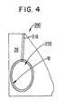
- FIG. 4 illustrates a cross-sectional view of the balloon catheter shown in FIGS. 1 and 2 while in the expanded configuration and while disposed within a previously formed tissue cavity.
- balloon 100 is in the expanded configuration such that balloon 120 expands to fill the previously formed tissue cavity.
- the previously formed tissue cavity is surrounded by margin tissue 10.
- the balloon catheter defines a kill zone 20 within which the margin tissue 10 is destroyed through ablation.
- FIG. 5 shows a side view of a balloon catheter according to another embodiment of the invention.
- Balloon catheter 500 includes catheter 510, balloon 520 and conductive element 530.
- Balloon catheter includes a conductive material integrally formed with balloon 520 such that the conductive material is arranged in paths referred to herein as conductive portions 521.
- FIG. 6 shows a cross-sectional view of balloon catheter 500 shown in FIG. 5 .
- balloon 520 includes conductive portions 521 and non-conductive portions 522.
- Balloon catheter 520 defines an interior 525.
- Balloon catheter 500 can operate as a monopolar device where the other pole (not shown) is disposed on the patient.
- FIG. 7 shows a cross-sectional view of a multi-layer balloon of a balloon catheter while in an expanded configuration, according to another embodiment of the invention.
- multi-layer balloon 720 includes two concentric balloon portions 723 and 727.
- Inner balloon 723 includes conductive portions 721 and non-conductive portions 722.
- outer balloon 727 includes conductive portions 728 and non-conductive portions 729.
- Inner balloon portion 723 and outer balloon portion 727 are arranged such that the conductive portions 721 of inner balloon portion 723 are aligned with the non-conductive portions 729 of outer balloon 727.
- the non-conductive portions 722 of inner balloon 723 are aligned with the conductive portions 728 of outer balloon 727.
- Disposed between inner balloon layer 723 and outer balloon layer 727 is an insulation layer 726.
- Multi-layer balloon 720 can operate as a bipolar device where each balloon portion 723 and 727 are separate poles. More specifically, insulation layer 726 allows conductive layer 721 of inner balloon layer 723 and conductive portion 728 of outer balloon layer 727 to separately receive RF energy and thereby define RF fields between adjacent conductive portions. For example, a given conductive portion 721 of inner balloon portion 723 can act as one pole, and the two adjacent conduction portions 728 of outer balloon portion 727 can act as the other poles.
- an RF field can be established between that conductive portion 721 of inner balloon portion 723 and one of the adjacent conductive portions 728 of outer balloon portion 727, and a separate RF field be established between that conductive portion 721 of inner balloon portion 723 and the remaining adjacent conductive portion 728 of outer balloon portion 727.
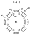
- FIG. 8 shows a cross-sectional view of a multi-layer balloon of a b'alloon catheter while in an expanded configuration, according to yet another embodiment of the invention.
- Multi-layer balloon 800 includes a conductive layer 823, an insulation layer 822 and a conductive layer 821.
- Conductive layer 821 and insulation layer 822 each have distinct segments where the one segment of the insulation layer 822 is disposed between the conductive layer 823 and an associated segment of the conductive layer 821.
- conductive layer 823 includes portions 824, upon which insulation 822 and 821 are not disposed.
- Balloon catheter 900 can operate as a bipolar device where conductive layer 823 acts as one pole and conductive layer 821 acts as another pole. Such a bipolar device can produce an RF field between the conductive layers 823 and 821 when energize by an RF generator (not shown in FIG. 8 ).
- multi-layer balloon 800 is shown as having no material between adjacent segments of insulation layer 822 and conductive layer 821, in alternative embodiments, an insulation layer can be provided between these adjacent segments of insulation layer and conductive layer. In yet another alternative embodiment, an additional insulation layer can be disposed on at least a portion of the conductive layer 821 and/or conductive layer 823.
- FIG. 9 depicts a cross-sectional view of a balloon catheter having a multi-lumen catheter, according to yet another embodiment of the invention.
- balloon catheter 900 includes a catheter 910 and balloon 920.
- Catheter 910 is a multi-layer catheter including a non-conductive layer 911, a conductive layer 912 and non-conductive layer 913.
- Non-conductive layer 911 can define lumen 914, which is in fluid communication with the interior 925 of balloon 920.
- Conductive layer 912 can be electrically coupled to the conductive material of balloon 920 such that energy received from a RF generator (not shown in FIG. 9 ) can be provided to the conductive material of 920 via conductive layer 912.
- Conductive layer 912 is thus an alternative to the conductive element 130 shown in FIG. 1 and conductive element 530 shown in FIG. 5 .
- the balloon catheter 900 shown in FIG. 9 can also include a guide wire 930, which can be disposed within lumen 914 of catheter 910.
- Guide wire 930 can be used to guide the balloon catheter to an appropriate position within a patient's body such as, for example, a previously formed tissue cavity thereby disposing balloon catheter into a desired location.
- FIG. 9 depicts the balloon catheter 900 in the expanded configuration, guide wire 930 will typically be used while the balloon catheter 900 is in a collapsed configuration.
- FIG. 10 shows a cross-sectional view of a balloon catheter having a multi-lumen catheter, according to yet another embodiment of the invention.
- Balloon catheter 1000 includes a multi-lumen catheter 1010 and a balloon 1020.
- Multi-lumen catheter 1010 includes lumens 1012, 1014 and 1016.
- Lumen 1012 can be used for example for a guide wire (not shown in FIG. 10 ).
- Lumens 1014 and 1016 can be used to allow the circulation of fluid within interior 1025 of balloon 1020. By controlling the rate at which fluid is introduced into and removed from interior 1025 of balloon 1020, the size of balloon 1020 can be controlled while also allowing the fluid within interior 1025 to circulate.
- balloon 1020 can be changed between a collapsed configuration and an expanded configuration.
- lumen 1014 can be an input lumen by which fluid can be introduced into interior 1025 via outlet 1015.
- Lumen 1016 can be an output lumen through which fluid can be withdrawn from interior 1025 through outlet 1017.
- This embodiment in which fluid can circulate within interior 1025 also allows a level of control in the manner by which tissue is ablated. More specifically, by allowing the circulation of fluid within interior 1025, the temperature of balloon 1020 can be, for example, reduced. Such a reduction in the temperature of balloon 1020 allows the enhancement of the kill zone of the marginal tissue. Said another way, if the contact temperature of the tissue surrounding balloon 1020 while in an expanded configuration increases too rapidly, the kill zone will be smaller than if the temperature of the marginal tissue is increased at a slower rate. This allows a larger kill zone than would otherwise be the case. Thus, by controlling the circulation of fluid, the temperature of balloon 1020 and therefore the temperature of the surrounding marginal tissue can be controlled thereby allowing the selection of a desired kill zone. Alternatively, the temperature of balloon 120 can be increased, providing a thermal ablation mechanism for necrosis of the margin tissue in addition to the RF ablation mechanism.
- FIG. 11 illustrates a cross-sectional view of a balloon catheter having multiple concentric balloons, according to an embodiment of the invention.
- Balloon catheter 1100 includes multi-lumen catheter 1110 and multi-layer balloon 1120.
- Multi-lumen catheter 1110 includes lumen 1112 and lumen 1114.
- Multi-layer balloon 1120 includes an inner balloon 1123 and an outer balloon 1127.
- Inner balloon 1123 defines an interior 1125.
- Interior 1129 is defined as the annular space between inner balloon 1123 and outer balloon 1127.
- Lumen 1112 of multi-lumen catheter 1110 is in fluid communication with interior 1125 of inner balloon 1123.
- lumen 1114 of multi-lumen catheter 1110 is in fluid communication with interior 1129 of outer balloon 1127.
- Inner balloon 1123 and outer balloon 1127 can each be formed from a conductive material.
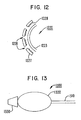
- FIG. 12 depicts a partial cross-sectional view of a balloon catheter having multiple concentric balloons, according to another embodiment of the invention.
- balloon 1220 includes an inner balloon 1223 and outer balloon 1227.
- Balloon 1220 can be connected to a multi-lumen catheter (not shown in FIG. 12 ) similar to multi-lumen catheter 1110 shown in FIG. 11 .
- Outer balloon 1227 includes a set of openings 1228 through which fluid can pass.
- outer balloon 1227 includes an irregular surface 1229, which provides separation between outer balloon 1227 and inner balloon 1223. This separation allows fluid to better pass between the inner balloon 1223 and outer balloon 1227, and exit the various openings 1228.
- FIG. 12 is not necessarily shown to scale and, consequently, the openings 1228 can be much smaller, thereby allowing the fluid to pass through the openings 1228 at a lower rate.
- the fluid exiting openings 1228 can provide enhanced conductivity to the margin tissue surrounding balloon 1220.
- the ablation process can be modified. For example, when a fluid having conductivity greater than the margin tissue exits opening 1228, the margin tissue with the fluid has a greater conductivity than would be the case without the fluid. As a consequence, a greater amount of tissue can be ablated. In other words, tissue can be ablation to a greater depth (i.e., a greater distance from the balloon) because a fluid being released into the margin produces an increased conductivity.
- the fluid can be any type of fluid that provides increased conductivity.
- the fluid can be a saline solution.
- the fluid can be a solution having ferric materials having ferric particles with a size of 1-100 microns in diameter, for example.
- FIG.13 depicts a side view of a balloon catheter having an atraumatic tip, according to an embodiment of the invention.
- balloon catheter 1300 includes catheter 1310, balloon 1320, and atraumatic tip 1350.
- Atraumatic tip 1350 can provide a blunt end to the balloon catheter 1300. Such a blunt end avoids the creation of any further punctures or holes within the tissue of the patient while the balloon catheter is in the collapsed configuration and moved within the patient.
- an atraumatic tip can be combined with any appropriate balloon catheter such as the above- described embodiments.
- FIG. 14 depicts a block diagram of an ablation system having a balloon catheter, according to an embodiment of the invention.
- balloon catheter system 1490 includes balloon catheter 1400, RF generator 1440, impedance measurement system 1450 and fluid regulator 1460.
- Balloon catheter 1400 includes a catheter 1410, a balloon 1420 and a conductive element 1430.
- RF generator 1440, impedance measurement system 1450 and fluid regulator 1460 are shown in FIG.14 in connection with balloon catheter 1300, they can be used with any of the balloon catheters described above.
- impedance measurement system 1450 and fluid regulator 1460 are optional for any of the embodiments described herein.
- RF generator 1440 is electrically coupled to conductive element 1430, which is electrically coupled to a conductive material of balloon 1420.
- Impedance measurement system 1450 can include a sensor (not shown in FIG. 14 ) disposed on an exterior balloon 1420. Such a sensor can allow the measurement of the impedance of the tissue proximate to the exterior of balloon 1420. The impedance of the tissue proximate to the exterior of balloon 1420 provides an indication of the extent to which that tissue is destroyed through the ablation process. Based on the impedance measurement of the tissue proximate to the exterior of balloon 1420, impedance measurement system 1450 can provide a signal to RF generator 1440.
- RF generator 1440 can control the amplitude, frequency, and/or power of the RF energy provided to the conductive material of balloon 1320 based on the signal received from impedance measurement system 1450. In this manner, the ablation process can be monitored and controlled.
- Fluid regulator 1360 can control the flow of fluid to the balloon 1420.
- balloon 1420 includes an outer balloon portion having openings (similar to the outer balloon portion 1227 shown in FIG. 12 )
- fluid regulator 1360 can control the rate at which fluid exits the opening and is introduced to the margin tissue.
- catheter 1410 is a multi-lumen catheter (similar to the multi-lumen catheter shown in FIG. 10 )
- fluid regulator 1360 can control the rate at which fluid circulates within the interior of the balloon 1420.
- FIG. 15 depicts a flowchart for making an ablation balloon, according to an embodiment of the invention. This process described in reference to FIG. 15 is similar to photolithography techniques used in the construction of integrated circuits. Although FIG. 15 describes a process for making many types of ablation balloons, for illustrative purposes FIG. 15 will be described in reference to the balloon shown in FIG. 8 having a first conductive layer, segments of an insulation layer and segments of a second conductive layer.
- a first portion of the balloon is masked based on a mask.
- the shape of the mask and the first portion of the balloon corresponds to the portions 824 of conductive layer 823 of balloon 820.
- an insulation layer on a second portion of the balloon is deposited. In other words, the insulation layer is disposed on the balloon excluding the masked portions of the balloon.
- a conductive layer on the second portion of the balloon is deposited.
- the conductive layer 821 is disposed on the insulation layer 822 of balloon.
- the mask is removed from the first portion of the balloon. As a result, the first portion of the balloon is exposed as such portions 824 of conductive layer 823 of balloon 800 shown in FIG. 8 .
- a second insulation layer (not shown in FIG. 8 ) can be deposited before the mask is removed. Once the mask is removed, the conductive layer will be disposed between the first insulation layer and the second insulation layer. Such a second insulation layer can provide a protective layer over the conductive layer.
- a second insulation layer (not shown in FIG. 8 ) can be deposited on the first portion and the second portion of the balloon after the mask has been removed.
- the second insulation layer will be disposed on the conductive layer for the second portion of the balloon and on the first portion of the balloon.
- Such a second insulation layer can provide a protective layer over the entire balloon.
- the balloon catheter can be used in combination with a radiation therapy device, such as, a radiation therapy device having a balloon-like structure inflated with a radioactive fluid of the type disclosed in U.S. Patent 6,083,148 .
- a radiation therapy device such as, a radiation therapy device having a balloon-like structure inflated with a radioactive fluid of the type disclosed in U.S. Patent 6,083,148 .
- Such radiation therapy device is understood to operate more effectively when the balloon-like structure of the radiation therapy device has a more spherical shape in its expanded configuration. Accordingly, it is desirable for the tissue cavity formed by the removal of a tumor to have a more spherical shape.
- An embodiment of the balloon catheter can be used to modify the shape of the tissue cavity formed by the removal of a tumor into a more spherical shape before use of a radiation therapy device. More specifically, the balloon catheter disposed within the tissue cavity can be activated to ablation the surrounding tissue thereby modifying the shape of the tissue cavity to a substantially spherical shape. The balloon catheter can be removed and the radiation therapy device can be inserted into the modified tissue cavity. The radiation therapy device can then apply the radiation therapy.
- the balloon can have an alternative shape and structure as may be appropriate for that application.
- the particular shape and structure of the balloon can be selected to match the particular anatomy associated with a given application.
- the various possible balloon structures include, for example, configurations where the balloon is compliant and configurations where the balloon has enough rigidity that the balloon takes on a predefined shape when expanded.
- possible balloon structures include, for example, configurations where the RF electrodes ablate surrounding tissue via direct contact, and configurations where the RF electrodes heat the fluid within the balloon and the tissue is ablated by the heated balloon.
- a balloon catheter can be used to treat prostatitis.
- the balloon catheter can be inserted transurethrally and, when in the expanded configuration, the balloon can have an hour-glass shape to provide an improved positioning of the balloon about the prostate lobes.
- the RF electrodes can be electrically activated to an appropriate level to heat via direct contact.
- the RF electrodes can be electrically activated to an appropriate level to heat the fluid within the balloon such that the heated balloon can ablate the prostate lobes.
- Such an embodiment can also be used to treat prostate cancer.
- a balloon catheter can be used for uterine ablation.
- the balloon in an expanded configuration can have a compliant structure that conforms to the shape of the uterine when the balloon is filled with a fluid.
- the balloon can be positioned in the uterine cavity transvaginally, inflated into the expanded configuration by filling the balloon with a fluid and then the RF electrodes can be electrically activated to ablate the endometrial lining of the uterus.
- the RF electrodes can be electrically activated to an appropriate level to heat the fluid within the balloon such that the heated balloon can ablate the endometrial lining of the uterus.
- the balloon catheter can be used to treat cervical cancer.
- the balloon in an expanded configuration can have a compliant structure in a mushroom-like shape.
- FIG. 16 shows a cross-sectional view of a balloon catheter in an expanded configuration, according to another embodiment of the invention.
- balloon catheter 1600 includes catheter 1610 and balloon 1620.
- Balloon 1620 has a compliant structure that when in an expanded configuration has a mushroom-like shape.
- Balloon 1620 includes balloon portions 1622 and balloon portion 1624, which are suitable for placement within and surrounding the cervix. More specifically, balloon portion 1624 can be disposed within and through the os; balloon portions 1622 can be disposed about and envelope the cervix.
- Balloon catheter 1600 can be dimensioned, for example, as a 5 to 7 French (1.65mm to 2.31mm) distal balloon shape by 3 cm that expands to a concave portion approximately 4 to 6 cm in diameter.
- the balloon here can be inflated into the expanded configuration by filling the balloon with a fluid and then the RF electrodes can be electrically activated to ablate the endometrial lining of the uterus.
- the RF electrodes can be electrically activated to an appropriate level to heat the fluid within the balloon such that the heated balloon can ablate the cervix.
Abstract
Description
- The invention relates generally to systems and methods for performing ablation. More specifically, the invention relates to a system and method for performing ablation using a balloon, for example, in a previously formed tissue cavity.
- Various known techniques exist for treating residual tumor tissue following the gross removal of the tumor. Such post-operative treatments include, for example, radiation techniques and brachytherapy techniques.
- These post-operative treatments suffer various shortcomings. For example, radiation techniques use common equipment that involve significant logistical challenges. In addition, radiation techniques are costly and time consuming. Radiation techniques typically involve multiple treatments over weeks and sometimes months. In addition, radiation often results in unintended damage to the tissue outside the target zone. In other words, rather than affecting the likely residual tissue, typically near the original tumor location, radiation techniques often adversely affect healthy tissue. Alternative focused-radiation therapy typically involves costly equipment with limited availability.
- Standard brachytherapy techniques typically require simultaneous placement of numerous catheters in the tumor and surrounding tissue with individual radioactive sources. Placement of these catheters can be costly, cumbersome and time consuming.
- Thus, a need exists for an improved system and method for treating residual tumor tissue following the gross removal of the tumor.
- A first aspect of the invention provides an apparatus comprising a catheter having a lumen; a conductive element disposed along the catheter; and a balloon having an interior in fluid communication with the lumen of the catheter, the balloon having a first layer formed of a conductive material conductively coupled to the conductive element, the balloon having a collapsed configuration and an expanded configuration, at least a portion of the balloon including a second layer and a third layer, the second layer being formed at least in part of an insulation material, the third layer being formed at least in part of a conductive material.
Surgical ablation probes for ablating tissue in pulmonary veins are known from, for example,US 2002/019627 . Such probes include a shaft having a circumferential ablation unit disposed thereon, the thermal ablation unit comprising a balloon having a thermal insulator disposed on a conductive surface to insulate all but a ring or band of the balloon. -
FIG.1 depicts a side view of a balloon catheter in an expanded configuration, according to an embodiment of the invention. -
FIG 2 depicts a cross-sectional view of the balloon catheter ofFIG. 1 taken along line 2-2 ofFIG.1 . -
FIG.3 shows a cross-sectional view of the balloon catheter shown inFIGS. 1 and 2 while in a collapsed configuration. -
FIG. 4 illustrates a cross-sectional view of the balloon catheter shown inFIGS.1 and 2 while in the expanded configuration and while disposed within a previously formed tissue cavity. -
Fig.5 shows a side view of a balloon catheter according to another embodiment of the invention. -
FIG.6 shows a cross-sectional view of the balloon catheter ofFIG.5 taken along line 6-6 ofFig.5 . -
FIG.7 shows a cross-sectional view of a multi-layer balloon of a balloon catheter while in an expanded configuration, according to another embodiment of the invention. -
FIG.8 shows a cross-sectional view of a multi-layer balloon of a balloon catheter while in an expanded configuration, according to yet another embodiment of the invention. -
FIG. 9 depicts a cross-sectional view of a balloon catheter having a multi-lumen catheter, according to yet another embodiment of the invention. -
FIG. 10 shows a cross-sectional view of a balloon catheter having a multi-lumen catheter, according to yet another embodiment of the invention. -
FIG.11 illustrates a cross-sectional view of a balloon catheter having multiple concentric balloons, according to an embodiment of the invention. -
FIG.12 depicts a partial cross-sectional view of a balloon catheter having multiple concentric balloons, according to another embodiment of the invention. -
FIG. 13 depicts a side view of a balloon catheter having an atraumatic tip, according to an embodiment of the invention. -
FIG. 14 depicts a block diagram of an ablation system having a balloon catheter, according to an embodiment of the invention. -
FIG. 15 is a flow chart illustrating a method for making a balloon according to an embodiment of the invention. -
FIG.16 shows a cross-sectional view of a balloon catheter in an expanded configuration, according to another embodiment of the invention. - Once a tumor has been removed, a tissue cavity remains. The tissue surrounding this cavity is the location within the patient where a reoccurrence of the tumor may most likely occur. Consequently, after a tumor has been removed, it is desirable to destroy the surrounding tissue (also referred herein as the "margin tissue"). Various embodiments described herein relate to balloon catheter devices and methods for ablating, for example, the margin tissue associated with a tissue cavity formed by the removal of a tumor.
- In one embodiment, an apparatus comprises a catheter having a lumen; a conductive element disposed along the catheter; and a balloon having an interior in fluid communication with the lumen of the catheter, the balloon having a first layer formed of a conductive material conductively coupled to the conductive element, the balloon having a collapsed configuration and an expanded configuration, at least a portion of the balloon including a second layer and a third layer, the second layer being formed at least in part of an insulation material, the third layer being formed at least in part of a conductive material.
- The balloon has the collapsed configuration, for example, when the balloon is exterior to a patient's body or being percutaneously disposed into the previously formed tissue cavity. The balloon in the collapsed configuration has a smaller size or volume than when the balloon is in the expanded configuration. The balloon has the expanded configuration, for example, when the balloon is disposed within the previously formed tissue cavity for ablation. In general, the balloon has a range of possible configurations, which include the collapsed configuration (typically at its smallest size or volume) and the expanded configuration corresponding to the size of the tissue cavity.
- The balloon is constructed to include electrically conductive portions. The electrical conductivity can be achieved by including electrically conductive material (such as for example, a conductive polymer or a non-conductive material that incorporates conductive elements such as metallic particles or other metallic elements) in the body of the balloon or by providing the balloon with a conductive layer or coating, such as a conductive ink, or with conductive elements attached to the balloon. In embodiments of the balloon where the conductive material is formed from a conductive polymer, the balloon can be formed, for example, using photolithography techniques. In embodiments of the balloon where the conductive material has a specific shape, the conductive material of the balloon can be formed from, for example, metallic stampings, wires or machined shapes. The term "electrically conductive" is used herein to mean the property of a material or medium permitting flow of electricity through its volume for the conditions to which it is normally subjected. In other words, although all materials and mediums are electrically conductive to some extent, electrically conductive materials or mediums considered herein exclude materials or mediums that are electrically conductive only at levels that are uncharacteristically high for typical ablation devices.
-
FIG.1 depicts a side view of a balloon catheter in an expanded configuration, according to an embodiment of the invention.Balloon catheter 100 includes acatheter 110, aballoon 120 and a conductive element 130 (e.g., a conductive wire covered with insulation).FIG.2 shows a cross-sectional view ofballoon catheter 100 while in the expanded configuration. As shown inFIG. 2 ,catheter 110 includes alumen 112 andballoon 120 defines aninterior 125. -
FIG.3 shows a cross-sectional view of the balloon catheter shown inFIGS.1 and 2 while the balloon catheter is in a collapsed configuration. Theballoon catheter 100 can be changed from a collapsed configuration to an expanded configuration by introducing a fluid intolumen 112. As the fluid traverseslumen 112, it can then fill theballoon cavity 125 thereby expandingballoon 120 into its expanded configuration. The fluid can be, for example, a liquid such as water or a saline solution, or can be a gas, such as air. Although theconductive element 130 is shown inFIG. 1 as being disposed along and on thecatheter 110, in alternative embodiments theconductive element 130 is disposed along thecatheter 110 and within thelumen 112. -
Balloon 120 can be formed, for example, of a conductive material or of a non-conductive material with conductive material uniformly distributed throughoutballoon 120. Such conductive material can be electrically coupled toconductive element 130 thereby allowing energy, such as radiofrequency (RF) energy, to be transferred fromconductive element 130 to the conductive material ofballoon 120. Such RF energy can be provided by an RF generator (not shown inFIGS. 1 through 3 ) coupled toconductive element 130.Balloon catheter 100 can operate as a monopolar device where the other pole (not shown) is disposed on the patient. -
FIG. 4 illustrates a cross-sectional view of the balloon catheter shown inFIGS. 1 and 2 while in the expanded configuration and while disposed within a previously formed tissue cavity. As shown inFIG. 4 ,balloon 100 is in the expanded configuration such thatballoon 120 expands to fill the previously formed tissue cavity. The previously formed tissue cavity is surrounded bymargin tissue 10. As the balloon catheter is activated, the balloon catheter defines akill zone 20 within which themargin tissue 10 is destroyed through ablation. -
FIG. 5 shows a side view of a balloon catheter according to another embodiment of the invention.Balloon catheter 500 includescatheter 510,balloon 520 andconductive element 530. Balloon catheter includes a conductive material integrally formed withballoon 520 such that the conductive material is arranged in paths referred to herein asconductive portions 521.FIG. 6 shows a cross-sectional view ofballoon catheter 500 shown inFIG. 5 . AsFIG. 6 shows,balloon 520 includesconductive portions 521 andnon-conductive portions 522.Balloon catheter 520 defines an interior 525.Balloon catheter 500 can operate as a monopolar device where the other pole (not shown) is disposed on the patient. -
FIG. 7 shows a cross-sectional view of a multi-layer balloon of a balloon catheter while in an expanded configuration, according to another embodiment of the invention. More particularly,multi-layer balloon 720 includes twoconcentric balloon portions Inner balloon 723 includesconductive portions 721 andnon-conductive portions 722. Similarly,outer balloon 727 includesconductive portions 728 andnon-conductive portions 729.Inner balloon portion 723 andouter balloon portion 727 are arranged such that theconductive portions 721 ofinner balloon portion 723 are aligned with thenon-conductive portions 729 ofouter balloon 727. Similarly, thenon-conductive portions 722 ofinner balloon 723 are aligned with theconductive portions 728 ofouter balloon 727. Disposed betweeninner balloon layer 723 andouter balloon layer 727 is aninsulation layer 726. -
Multi-layer balloon 720 can operate as a bipolar device where eachballoon portion insulation layer 726 allowsconductive layer 721 ofinner balloon layer 723 andconductive portion 728 ofouter balloon layer 727 to separately receive RF energy and thereby define RF fields between adjacent conductive portions. For example, a givenconductive portion 721 ofinner balloon portion 723 can act as one pole, and the twoadjacent conduction portions 728 ofouter balloon portion 727 can act as the other poles. Following this example, an RF field can be established between thatconductive portion 721 ofinner balloon portion 723 and one of the adjacentconductive portions 728 ofouter balloon portion 727, and a separate RF field be established between thatconductive portion 721 ofinner balloon portion 723 and the remaining adjacentconductive portion 728 ofouter balloon portion 727. -
FIG. 8 shows a cross-sectional view of a multi-layer balloon of a b'alloon catheter while in an expanded configuration, according to yet another embodiment of the invention.Multi-layer balloon 800 includes aconductive layer 823, aninsulation layer 822 and aconductive layer 821.Conductive layer 821 andinsulation layer 822 each have distinct segments where the one segment of theinsulation layer 822 is disposed between theconductive layer 823 and an associated segment of theconductive layer 821. Thus,conductive layer 823 includesportions 824, upon whichinsulation Balloon catheter 900 can operate as a bipolar device whereconductive layer 823 acts as one pole andconductive layer 821 acts as another pole. Such a bipolar device can produce an RF field between theconductive layers FIG. 8 ). - Although
multi-layer balloon 800 is shown as having no material between adjacent segments ofinsulation layer 822 andconductive layer 821, in alternative embodiments, an insulation layer can be provided between these adjacent segments of insulation layer and conductive layer. In yet another alternative embodiment, an additional insulation layer can be disposed on at least a portion of theconductive layer 821 and/orconductive layer 823. -
FIG. 9 depicts a cross-sectional view of a balloon catheter having a multi-lumen catheter, according to yet another embodiment of the invention. As shown inFIG. 9 ,balloon catheter 900 includes acatheter 910 andballoon 920.Catheter 910 is a multi-layer catheter including anon-conductive layer 911, aconductive layer 912 andnon-conductive layer 913.Non-conductive layer 911 can definelumen 914, which is in fluid communication with theinterior 925 ofballoon 920.Conductive layer 912 can be electrically coupled to the conductive material ofballoon 920 such that energy received from a RF generator (not shown inFIG. 9 ) can be provided to the conductive material of 920 viaconductive layer 912.Conductive layer 912 is thus an alternative to theconductive element 130 shown inFIG. 1 andconductive element 530 shown inFIG. 5 . - The
balloon catheter 900 shown inFIG. 9 can also include aguide wire 930, which can be disposed withinlumen 914 ofcatheter 910.Guide wire 930 can be used to guide the balloon catheter to an appropriate position within a patient's body such as, for example, a previously formed tissue cavity thereby disposing balloon catheter into a desired location. AlthoughFIG. 9 depicts theballoon catheter 900 in the expanded configuration,guide wire 930 will typically be used while theballoon catheter 900 is in a collapsed configuration. -
FIG. 10 shows a cross-sectional view of a balloon catheter having a multi-lumen catheter, according to yet another embodiment of the invention.Balloon catheter 1000 includes amulti-lumen catheter 1010 and aballoon 1020.Multi-lumen catheter 1010 includeslumens Lumen 1012 can be used for example for a guide wire (not shown inFIG. 10 ).Lumens balloon 1020. By controlling the rate at which fluid is introduced into and removed from interior 1025 ofballoon 1020, the size ofballoon 1020 can be controlled while also allowing the fluid within interior 1025 to circulate. More particularly, by controlling the difference in the rates at which fluid is introduced into and withdrawn from interior 1025,balloon 1020 can be changed between a collapsed configuration and an expanded configuration. Following the example shown inFIG. 10 ,lumen 1014 can be an input lumen by which fluid can be introduced into interior 1025 viaoutlet 1015.Lumen 1016 can be an output lumen through which fluid can be withdrawn from interior 1025 throughoutlet 1017. - This embodiment in which fluid can circulate within interior 1025 also allows a level of control in the manner by which tissue is ablated. More specifically, by allowing the circulation of fluid within interior 1025, the temperature of
balloon 1020 can be, for example, reduced. Such a reduction in the temperature ofballoon 1020 allows the enhancement of the kill zone of the marginal tissue. Said another way, if the contact temperature of thetissue surrounding balloon 1020 while in an expanded configuration increases too rapidly, the kill zone will be smaller than if the temperature of the marginal tissue is increased at a slower rate. This allows a larger kill zone than would otherwise be the case. Thus, by controlling the circulation of fluid, the temperature ofballoon 1020 and therefore the temperature of the surrounding marginal tissue can be controlled thereby allowing the selection of a desired kill zone. Alternatively, the temperature ofballoon 120 can be increased, providing a thermal ablation mechanism for necrosis of the margin tissue in addition to the RF ablation mechanism. -
FIG. 11 illustrates a cross-sectional view of a balloon catheter having multiple concentric balloons, according to an embodiment of the invention.Balloon catheter 1100 includes multi-lumen catheter 1110 and multi-layer balloon 1120. Multi-lumen catheter 1110 includeslumen 1112 andlumen 1114. Multi-layer balloon 1120 includes aninner balloon 1123 and anouter balloon 1127.Inner balloon 1123 defines an interior 1125.Interior 1129 is defined as the annular space betweeninner balloon 1123 andouter balloon 1127.Lumen 1112 of multi-lumen catheter 1110 is in fluid communication with interior 1125 ofinner balloon 1123. Similarly,lumen 1114 of multi-lumen catheter 1110 is in fluid communication with interior 1129 ofouter balloon 1127.Inner balloon 1123 andouter balloon 1127 can each be formed from a conductive material. -
FIG. 12 depicts a partial cross-sectional view of a balloon catheter having multiple concentric balloons, according to another embodiment of the invention. As shown inFIG. 12 ,balloon 1220 includes aninner balloon 1223 andouter balloon 1227.Balloon 1220 can be connected to a multi-lumen catheter (not shown inFIG. 12 ) similar to multi-lumen catheter 1110 shown inFIG. 11 .Outer balloon 1227 includes a set ofopenings 1228 through which fluid can pass. In addition,outer balloon 1227 includes anirregular surface 1229, which provides separation betweenouter balloon 1227 andinner balloon 1223. This separation allows fluid to better pass between theinner balloon 1223 andouter balloon 1227, and exit thevarious openings 1228.FIG. 12 is not necessarily shown to scale and, consequently, theopenings 1228 can be much smaller, thereby allowing the fluid to pass through theopenings 1228 at a lower rate. - The
fluid exiting openings 1228 can provide enhanced conductivity to the margintissue surrounding balloon 1220. By providing enhanced conductivity, the ablation process can be modified. For example, when a fluid having conductivity greater than the margin tissue exitsopening 1228, the margin tissue with the fluid has a greater conductivity than would be the case without the fluid. As a consequence, a greater amount of tissue can be ablated. In other words, tissue can be ablation to a greater depth (i.e., a greater distance from the balloon) because a fluid being released into the margin produces an increased conductivity. - The fluid can be any type of fluid that provides increased conductivity. For example, the fluid can be a saline solution. Alternatively, the fluid can be a solution having ferric materials having ferric particles with a size of 1-100 microns in diameter, for example.
-
FIG.13 depicts a side view of a balloon catheter having an atraumatic tip, according to an embodiment of the invention. As shown in FIG.32,balloon catheter 1300 includes catheter 1310,balloon 1320, and atraumatic tip 1350. Atraumatic tip 1350 can provide a blunt end to theballoon catheter 1300. Such a blunt end avoids the creation of any further punctures or holes within the tissue of the patient while the balloon catheter is in the collapsed configuration and moved within the patient. Although shown in connection withballoon catheter 1300, an atraumatic tip can be combined with any appropriate balloon catheter such as the above- described embodiments. -
FIG. 14 depicts a block diagram of an ablation system having a balloon catheter, according to an embodiment of the invention. As shown inFIG. 14 ,balloon catheter system 1490 includesballoon catheter 1400,RF generator 1440,impedance measurement system 1450 andfluid regulator 1460.Balloon catheter 1400 includes acatheter 1410, aballoon 1420 and aconductive element 1430. AlthoughRF generator 1440,impedance measurement system 1450 andfluid regulator 1460 are shown inFIG.14 in connection withballoon catheter 1300, they can be used with any of the balloon catheters described above. In addition,impedance measurement system 1450 andfluid regulator 1460 are optional for any of the embodiments described herein. -
RF generator 1440 is electrically coupled toconductive element 1430, which is electrically coupled to a conductive material ofballoon 1420.Impedance measurement system 1450 can include a sensor (not shown inFIG. 14 ) disposed on anexterior balloon 1420. Such a sensor can allow the measurement of the impedance of the tissue proximate to the exterior ofballoon 1420. The impedance of the tissue proximate to the exterior ofballoon 1420 provides an indication of the extent to which that tissue is destroyed through the ablation process. Based on the impedance measurement of the tissue proximate to the exterior ofballoon 1420,impedance measurement system 1450 can provide a signal toRF generator 1440.RF generator 1440 can control the amplitude, frequency, and/or power of the RF energy provided to the conductive material ofballoon 1320 based on the signal received fromimpedance measurement system 1450. In this manner, the ablation process can be monitored and controlled. - Fluid regulator 1360 can control the flow of fluid to the
balloon 1420. For example, whenballoon 1420 includes an outer balloon portion having openings (similar to theouter balloon portion 1227 shown inFIG. 12 ), fluid regulator 1360 can control the rate at which fluid exits the opening and is introduced to the margin tissue. For another example, whencatheter 1410 is a multi-lumen catheter (similar to the multi-lumen catheter shown inFIG. 10 ), fluid regulator 1360 can control the rate at which fluid circulates within the interior of theballoon 1420. -
FIG. 15 depicts a flowchart for making an ablation balloon, according to an embodiment of the invention. This process described in reference toFIG. 15 is similar to photolithography techniques used in the construction of integrated circuits. AlthoughFIG. 15 describes a process for making many types of ablation balloons, for illustrative purposesFIG. 15 will be described in reference to the balloon shown inFIG. 8 having a first conductive layer, segments of an insulation layer and segments of a second conductive layer. - At
step 1500, a first portion of the balloon is masked based on a mask. Following the example ofFIG. 8 , the shape of the mask and the first portion of the balloon corresponds to theportions 824 ofconductive layer 823 of balloon 820. Atstep 1510, an insulation layer on a second portion of the balloon is deposited. In other words, the insulation layer is disposed on the balloon excluding the masked portions of the balloon. Atstep 1520, a conductive layer on the second portion of the balloon is deposited. Following the example ofFIG. 8 , theconductive layer 821 is disposed on theinsulation layer 822 of balloon. Atstep 1530, the mask is removed from the first portion of the balloon. As a result, the first portion of the balloon is exposed assuch portions 824 ofconductive layer 823 ofballoon 800 shown inFIG. 8 . - In alternative embodiments, a second insulation layer (not shown in
FIG. 8 ) can be deposited before the mask is removed. Once the mask is removed, the conductive layer will be disposed between the first insulation layer and the second insulation layer. Such a second insulation layer can provide a protective layer over the conductive layer. - In another alternative embodiment, a second insulation layer (not shown in
FIG. 8 ) can be deposited on the first portion and the second portion of the balloon after the mask has been removed. Thus, once the mask is removed, the second insulation layer will be disposed on the conductive layer for the second portion of the balloon and on the first portion of the balloon. Such a second insulation layer can provide a protective layer over the entire balloon. - In one alternative embodiment, the balloon catheter can be used in combination with a radiation therapy device, such as, a radiation therapy device having a balloon-like structure inflated with a radioactive fluid of the type disclosed in
U.S. Patent 6,083,148 . Such radiation therapy device is understood to operate more effectively when the balloon-like structure of the radiation therapy device has a more spherical shape in its expanded configuration. Accordingly, it is desirable for the tissue cavity formed by the removal of a tumor to have a more spherical shape. - An embodiment of the balloon catheter can be used to modify the shape of the tissue cavity formed by the removal of a tumor into a more spherical shape before use of a radiation therapy device. More specifically, the balloon catheter disposed within the tissue cavity can be activated to ablation the surrounding tissue thereby modifying the shape of the tissue cavity to a substantially spherical shape. The balloon catheter can be removed and the radiation therapy device can be inserted into the modified tissue cavity. The radiation therapy device can then apply the radiation therapy.
- Although some embodiments of the invention have been described above, for example, in connection with ablating margin tissue after a tumor has been removed, some embodiments can be used in other applications. For such other applications, the balloon can have an alternative shape and structure as may be appropriate for that application. In other words, the particular shape and structure of the balloon can be selected to match the particular anatomy associated with a given application. The various possible balloon structures include, for example, configurations where the balloon is compliant and configurations where the balloon has enough rigidity that the balloon takes on a predefined shape when expanded. Alternatively, possible balloon structures include, for example, configurations where the RF electrodes ablate surrounding tissue via direct contact, and configurations where the RF electrodes heat the fluid within the balloon and the tissue is ablated by the heated balloon. These various alternative applications and structures are discussed below.
- In one embodiment, for example, a balloon catheter can be used to treat prostatitis. For such an application, the balloon catheter can be inserted transurethrally and, when in the expanded configuration, the balloon can have an hour-glass shape to provide an improved positioning of the balloon about the prostate lobes. Once positioned and disposed within the expanded configuration, the RF electrodes can be electrically activated to an appropriate level to heat via direct contact. Alternatively, the RF electrodes can be electrically activated to an appropriate level to heat the fluid within the balloon such that the heated balloon can ablate the prostate lobes. Such an embodiment can also be used to treat prostate cancer.
- In another embodiment, a balloon catheter can be used for uterine ablation. For such an application, the balloon in an expanded configuration can have a compliant structure that conforms to the shape of the uterine when the balloon is filled with a fluid. In other words, the balloon can be positioned in the uterine cavity transvaginally, inflated into the expanded configuration by filling the balloon with a fluid and then the RF electrodes can be electrically activated to ablate the endometrial lining of the uterus. As discussed above, in an alternative, the RF electrodes can be electrically activated to an appropriate level to heat the fluid within the balloon such that the heated balloon can ablate the endometrial lining of the uterus.
- In yet another embodiment, the balloon catheter can be used to treat cervical cancer. For such an application, the balloon in an expanded configuration can have a compliant structure in a mushroom-like shape.
FIG. 16 shows a cross-sectional view of a balloon catheter in an expanded configuration, according to another embodiment of the invention. - As shown in
FIG. 16 , balloon catheter 1600 includescatheter 1610 andballoon 1620.Balloon 1620 has a compliant structure that when in an expanded configuration has a mushroom-like shape.Balloon 1620 includesballoon portions 1622 andballoon portion 1624, which are suitable for placement within and surrounding the cervix. More specifically,balloon portion 1624 can be disposed within and through the os;balloon portions 1622 can be disposed about and envelope the cervix. Balloon catheter 1600 can be dimensioned, for example, as a 5 to 7 French (1.65mm to 2.31mm) distal balloon shape by 3 cm that expands to a concave portion approximately 4 to 6 cm in diameter. - Similar to the discussion above, once positioned, the balloon here can be inflated into the expanded configuration by filling the balloon with a fluid and then the RF electrodes can be electrically activated to ablate the endometrial lining of the uterus. Alternatively, the RF electrodes can be electrically activated to an appropriate level to heat the fluid within the balloon such that the heated balloon can ablate the cervix.
Claims (11)
- An apparatus (100, 500, 900, 1000) comprisinga catheter (110, 510, 910) having a lumen (112, 1012, 1110);a conductive element (130) disposed along the catheter; anda balloon (120, 520, 720, 800, 1020) having an interior in fluid communication with the lumen of the catheter (110), the balloon (120, 520, 720, 800, 1020) having a first layer formed of a conductive material conductively coupled to the conductive element (130, 530), the balloon (120, 520, 720, 800, 1020) having a collapsed configuration and an expanded configuration, at least a portion of the balloon including a second layer and a third layer, the second layer being formed at least in part of an insulation material (822), the third layer being formed at least in part of a conductive (823) material.
- The apparatus of claim 1, wherein:(i) the balloon in the expanded configuration having a size associated with a previously-formed tissue cavity; or(ii) the conductive material of the first layer of the balloon includes a plurality of conductive portions (521, 721, 821, 824), two adjacent conductive portions from the plurality of conductive portions being separated by an insulation portion (726, 822) from a plurality of insulation portions;the first layer of the balloon includes a plurality of conductive portions (824), two adjacent conductive portions from the plurality of conductive portions (824) of the first layer of the balloon being separated by an insulation portion from a plurality of insulation portions,
the third layer of the balloon includes a plurality of conductive portions (824), two adjacent conductive portions from the plurality of conductive portions (824) of the third layer of the balloon being separated by an insulation portion from a plurality of insulation portions,
each conductive portion (824) from the plurality of conductive portions of the first layer of the balloon being offset from a corresponding conductive portion from the plurality of conductive portions of the third layer of the balloon. - The apparatus according to claim 1 or claim 2, wherein the balloon includes at least one electrode.
- The apparatus according to any one of claims 1 to 3, wherein the first layer and the third layer of the balloon are each a bipolar electrode.
- The apparatus according to any one of the preceding claims wherein the lumen of the catheter is a first lumen (1112), wherein:the catheter has a first end portion, a second end portion and a second lumen (1114), the first end portion of the catheter being disposed within the balloon, the first end portion of the catheter having an inlet associated with the first lumen (1112) and an outlet associated with the second lumen (1114),a fluid regulator (1460) coupled to the second end portion (1114) of the catheter, the fluid regulator (1460) configured to circulate a fluid at a temperature within the balloon (1020) less than a temperature of the conductive material of the balloon.
- The apparatus according to any one of the preceding claims wherein the balloon is a first balloon, the lumen of the catheter being a first lumen, further comprising:(i) a second balloon (1127) disposed outside of the first balloon (1123), the second balloon (1127) being fluid permeable, the catheter including a second lumen (1114) in fluid communication with the second balloon; or(ii) a second balloon (1127) disposed outside of the first balloon (1229), the second balloon (1127) being fluid permeable, the catheter including a second lumen in fluid communication with the second balloon (1127); anda fluid regulator (1460) coupled to the second lumen of the catheter, the fluid regulator (1460) configured to control a rate of fluid per fusing from the second balloon based on an impedance associated with the second balloon.
- The apparatus according to any one of the preceding claims further comprising:(i) an atraumatic tip (1350) disposed at a distal end of the balloon; or(ii) a guide wire (930) disposed within the lumen of the catheter and an interior of the balloon; or(iii) the catheter has a first non-conductive layer (911), a second non-conductive layer (913) and a conductive layer (912), the conductive layer being disposed between the first non-conductive layer and the second non-conductive layer, the conductive layer (912) being electrically coupled to the conductive material of the balloon (920).
- An apparatus according to anyone of claims 1 to 7, for treating a margin tissue associated with a tissue cavity after removal of a tissue mass, wherein the balloon has at least one electrode and defines an interior in fluid communication with the lumen of the catheter, the balloon in the expanded configuration corresponding to the tissue cavity.
- The apparatus of claim 8, wherein:(i) the at least one electrode of the balloon is formed with the balloon; or(ii) the at least one electrode of the balloon includes a plurality of conductive portions (521, 721, 821, 824), two adjacent conductive portions from the plurality of conductive portions being separated by an insulation portion from a plurality of insulation portions; or(iii) the at least one electrode is disposed within the first layer of balloon (821), the third layer of the balloon includes its own at least one electrode (823); optionally further comprising:a radio-frequency generator (1440) coupled to the at least one electrode of the first layer of the balloon and the at least one electrode of the third layer of the balloon, the first layer of the balloon and the third layer of the balloon defining a bipolar configuration.
- A method for making an expandable ablation balloon (820) formed of a conductive material and having a first portion (824) and a second portion, comprising:masking the first portion of a balloon (820) based on a mask (1500);depositing an insulation layer on the second portion of the balloon (1510);depositing a conductive layer (821) on the second portion of the balloon (1520); andremoving the mask from the first portion of the balloon (1530).
- The method of claim 10, the insulation layer being a first insulation layer, the method further comprising:(i) depositing a second insulation layer on the second portion of the balloon before the removing the mask from the first portion of the balloon; or(ii) depositing a second insulation layer on the first portion of the balloon and the second portion of the balloon after the removing the mask from the first portion of the balloon.
Applications Claiming Priority (2)
| Application Number | Priority Date | Filing Date | Title |
|---|---|---|---|
| US10/768,037 US7371231B2 (en) | 2004-02-02 | 2004-02-02 | System and method for performing ablation using a balloon |
| PCT/US2004/041427 WO2005074829A1 (en) | 2004-02-02 | 2004-12-13 | System and method for performing ablation using a balloon |
Publications (2)
| Publication Number | Publication Date |
|---|---|
| EP1715798A1 EP1715798A1 (en) | 2006-11-02 |
| EP1715798B1 true EP1715798B1 (en) | 2009-04-22 |
Family
ID=34807785
Family Applications (1)
| Application Number | Title | Priority Date | Filing Date |
|---|---|---|---|
| EP04813699A Not-in-force EP1715798B1 (en) | 2004-02-02 | 2004-12-13 | System and method for performing ablation using a balloon |
Country Status (7)
| Country | Link |
|---|---|
| US (4) | US7371231B2 (en) |
| EP (1) | EP1715798B1 (en) |
| JP (1) | JP4646924B2 (en) |
| AT (1) | ATE429184T1 (en) |
| DE (1) | DE602004020808D1 (en) |
| ES (1) | ES2344008T3 (en) |
| WO (1) | WO2005074829A1 (en) |
Cited By (10)
| Publication number | Priority date | Publication date | Assignee | Title |
|---|---|---|---|---|
| US8364237B2 (en) | 2005-03-28 | 2013-01-29 | Vessix Vascular, Inc. | Tuned RF energy for selective treatment of atheroma and other target tissues and/or structures |
| US8396548B2 (en) | 2008-11-14 | 2013-03-12 | Vessix Vascular, Inc. | Selective drug delivery in a lumen |
| US8401667B2 (en) | 2008-11-17 | 2013-03-19 | Vessix Vascular, Inc. | Selective accumulation of energy with or without knowledge of tissue topography |
| US8496653B2 (en) | 2007-04-23 | 2013-07-30 | Boston Scientific Scimed, Inc. | Thrombus removal |
| US8551096B2 (en) | 2009-05-13 | 2013-10-08 | Boston Scientific Scimed, Inc. | Directional delivery of energy and bioactives |
| US8920414B2 (en) | 2004-09-10 | 2014-12-30 | Vessix Vascular, Inc. | Tuned RF energy and electrical tissue characterization for selective treatment of target tissues |
| US9125667B2 (en) | 2004-09-10 | 2015-09-08 | Vessix Vascular, Inc. | System for inducing desirable temperature effects on body tissue |
| US9125666B2 (en) | 2003-09-12 | 2015-09-08 | Vessix Vascular, Inc. | Selectable eccentric remodeling and/or ablation of atherosclerotic material |
| US9277955B2 (en) | 2010-04-09 | 2016-03-08 | Vessix Vascular, Inc. | Power generating and control apparatus for the treatment of tissue |
| US9974607B2 (en) | 2006-10-18 | 2018-05-22 | Vessix Vascular, Inc. | Inducing desirable temperature effects on body tissue |
Families Citing this family (208)
| Publication number | Priority date | Publication date | Assignee | Title |
|---|---|---|---|---|
| US7756583B2 (en) | 2002-04-08 | 2010-07-13 | Ardian, Inc. | Methods and apparatus for intravascularly-induced neuromodulation |
| US8347891B2 (en) | 2002-04-08 | 2013-01-08 | Medtronic Ardian Luxembourg S.A.R.L. | Methods and apparatus for performing a non-continuous circumferential treatment of a body lumen |
| US20040226556A1 (en) | 2003-05-13 | 2004-11-18 | Deem Mark E. | Apparatus for treating asthma using neurotoxin |
| JP4564046B2 (en) * | 2004-02-25 | 2010-10-20 | エルベ エレクトロメディツィン ゲーエムベーハー | A device for interstitial coagulation of tissue |
| US9713730B2 (en) | 2004-09-10 | 2017-07-25 | Boston Scientific Scimed, Inc. | Apparatus and method for treatment of in-stent restenosis |
| US7949407B2 (en) | 2004-11-05 | 2011-05-24 | Asthmatx, Inc. | Energy delivery devices and methods |
| EP1906923B1 (en) | 2005-07-22 | 2018-01-24 | The Foundry, LLC | Systems and methods for delivery of a therapeutic agent |
| US20070083192A1 (en) * | 2005-10-07 | 2007-04-12 | Eric Welch | Apparatus and method for ablation of targeted tissue |
| US8204600B2 (en) * | 2005-11-22 | 2012-06-19 | Mayo Foundation For Medical Education And Research | Detecting and treating nervous system disorders |
| US8540666B2 (en) * | 2005-12-21 | 2013-09-24 | Boston Scientific Scimed, Inc. | Echogenic occlusive balloon and delivery system |
| US20090326513A1 (en) * | 2006-01-31 | 2009-12-31 | Deutsch Harvey L | Device for placing an occlusion removing structure in an open-ended tubular structure |
| US8019435B2 (en) | 2006-05-02 | 2011-09-13 | Boston Scientific Scimed, Inc. | Control of arterial smooth muscle tone |
| US8486127B2 (en) * | 2006-05-24 | 2013-07-16 | Kambiz Dowlatshahi | High temperature thermal therapy of breast cancer |
| WO2007146215A2 (en) * | 2006-06-12 | 2007-12-21 | Pankaj Patel | Endoscopically introducible expandable cautery device |
| US20070287994A1 (en) * | 2006-06-12 | 2007-12-13 | Pankaj Amrit Patel | Endoscopically Introducible Expandable Bipolar Probe |
| US8728140B2 (en) | 2006-11-06 | 2014-05-20 | Stacy Lee Feemster | Therapeutic intra-vaginal devices and methods |
| US20080154238A1 (en) * | 2006-12-01 | 2008-06-26 | Mcguckin James F | Endometrial ablation device |
| US20080287984A1 (en) * | 2007-05-18 | 2008-11-20 | Jan Weber | Medical balloons and methods of making the same |
| US8251992B2 (en) | 2007-07-06 | 2012-08-28 | Tyco Healthcare Group Lp | Method and apparatus for gastrointestinal tract ablation to achieve loss of persistent and/or recurrent excess body weight following a weight-loss operation |
| US8483831B1 (en) | 2008-02-15 | 2013-07-09 | Holaira, Inc. | System and method for bronchial dilation |
| EP2662046B1 (en) | 2008-05-09 | 2023-03-15 | Nuvaira, Inc. | Systems and assemblies for treating a bronchial tree |
| US8939991B2 (en) | 2008-06-08 | 2015-01-27 | Hotspur Technologies, Inc. | Apparatus and methods for removing obstructive material from body lumens |
| US20090318914A1 (en) * | 2008-06-18 | 2009-12-24 | Utley David S | System and method for ablational treatment of uterine cervical neoplasia |
| US9101382B2 (en) * | 2009-02-18 | 2015-08-11 | Hotspur Technologies, Inc. | Apparatus and methods for treating obstructions within body lumens |
| US8945160B2 (en) | 2008-07-03 | 2015-02-03 | Hotspur Technologies, Inc. | Apparatus and methods for treating obstructions within body lumens |
| US8500732B2 (en) | 2008-10-21 | 2013-08-06 | Hermes Innovations Llc | Endometrial ablation devices and systems |
| US8197476B2 (en) | 2008-10-21 | 2012-06-12 | Hermes Innovations Llc | Tissue ablation systems |
| US8821486B2 (en) | 2009-11-13 | 2014-09-02 | Hermes Innovations, LLC | Tissue ablation systems and methods |
| US9662163B2 (en) | 2008-10-21 | 2017-05-30 | Hermes Innovations Llc | Endometrial ablation devices and systems |
| US8540708B2 (en) * | 2008-10-21 | 2013-09-24 | Hermes Innovations Llc | Endometrial ablation method |
| US8197477B2 (en) | 2008-10-21 | 2012-06-12 | Hermes Innovations Llc | Tissue ablation methods |
| US8382753B2 (en) * | 2008-10-21 | 2013-02-26 | Hermes Innovations, LLC | Tissue ablation methods |
| US10987494B2 (en) | 2008-11-11 | 2021-04-27 | Covidien Lp | Pleated or folded catheter-mounted balloon |
| CA2743140A1 (en) * | 2008-11-11 | 2010-05-20 | Shifamed, Llc | Low profile electrode assembly |
| US9795442B2 (en) | 2008-11-11 | 2017-10-24 | Shifamed Holdings, Llc | Ablation catheters |
| WO2013049601A2 (en) * | 2011-09-30 | 2013-04-04 | Covidien Lp | Energy delivery device and methods of use |
| US11376061B2 (en) | 2008-11-11 | 2022-07-05 | Covidien Lp | Energy delivery device and methods of use |
| US9254168B2 (en) | 2009-02-02 | 2016-02-09 | Medtronic Advanced Energy Llc | Electro-thermotherapy of tissue using penetrating microelectrode array |
| US20120109057A1 (en) | 2009-02-18 | 2012-05-03 | Hotspur Technologies, Inc. | Apparatus and methods for treating obstructions within body lumens |
| US20100228239A1 (en) * | 2009-03-09 | 2010-09-09 | Cytyc Corporation | Ablation device with suction capability |
| CN102481433B (en) * | 2009-06-24 | 2014-12-31 | 施菲姆德控股有限责任公司 | Steerable medical delivery devices and methods of use |
| US9345541B2 (en) | 2009-09-08 | 2016-05-24 | Medtronic Advanced Energy Llc | Cartridge assembly for electrosurgical devices, electrosurgical unit and methods of use thereof |
| WO2011053599A1 (en) | 2009-10-26 | 2011-05-05 | Hermes Innovations Llc | Endometrial ablation devices and system |
| CN107049479B (en) | 2009-10-27 | 2020-10-16 | 努瓦拉公司 | Delivery device with coolable energy emitting assembly |
| US8715278B2 (en) * | 2009-11-11 | 2014-05-06 | Minerva Surgical, Inc. | System for endometrial ablation utilizing radio frequency |
| US8343078B2 (en) * | 2009-11-11 | 2013-01-01 | Minerva Surgical, Inc. | Methods for evaluating the integrity of a uterine cavity |
| US8911439B2 (en) | 2009-11-11 | 2014-12-16 | Holaira, Inc. | Non-invasive and minimally invasive denervation methods and systems for performing the same |
| KR101820542B1 (en) | 2009-11-11 | 2018-01-19 | 호라이라 인코포레이티드 | Systems, apparatuses, and methods for treating tissue and controlling stenosis |
| US8529562B2 (en) | 2009-11-13 | 2013-09-10 | Minerva Surgical, Inc | Systems and methods for endometrial ablation |
| US11896282B2 (en) | 2009-11-13 | 2024-02-13 | Hermes Innovations Llc | Tissue ablation systems and method |
| US9289257B2 (en) * | 2009-11-13 | 2016-03-22 | Minerva Surgical, Inc. | Methods and systems for endometrial ablation utilizing radio frequency |
| US9421059B2 (en) | 2010-04-27 | 2016-08-23 | Minerva Surgical, Inc. | Device for endometrial ablation having an expandable seal for a cervical canal |
| US8926629B2 (en) | 2010-02-24 | 2015-01-06 | Minerva Surgical, Inc. | Systems and methods for endometrial ablation |
| US9592090B2 (en) | 2010-03-11 | 2017-03-14 | Medtronic Advanced Energy Llc | Bipolar electrosurgical cutter with position insensitive return electrode contact |
| JP2013521995A (en) | 2010-03-24 | 2013-06-13 | シファメド・ホールディングス・エルエルシー | Endovascular tissue destruction |
| AU2011237666A1 (en) | 2010-04-06 | 2012-11-08 | Holaira, Inc. | System and method for pulmonary treatment |
| US10575893B2 (en) | 2010-04-06 | 2020-03-03 | Nuvaira, Inc. | System and method for pulmonary treatment |
| US9192790B2 (en) | 2010-04-14 | 2015-11-24 | Boston Scientific Scimed, Inc. | Focused ultrasonic renal denervation |
| US9655677B2 (en) | 2010-05-12 | 2017-05-23 | Shifamed Holdings, Llc | Ablation catheters including a balloon and electrodes |
| CN103118620B (en) | 2010-05-12 | 2015-09-23 | 施菲姆德控股有限责任公司 | The electrode assemblie of low profile |
| US8473067B2 (en) | 2010-06-11 | 2013-06-25 | Boston Scientific Scimed, Inc. | Renal denervation and stimulation employing wireless vascular energy transfer arrangement |
| US8920417B2 (en) | 2010-06-30 | 2014-12-30 | Medtronic Advanced Energy Llc | Electrosurgical devices and methods of use thereof |
| US8956348B2 (en) | 2010-07-21 | 2015-02-17 | Minerva Surgical, Inc. | Methods and systems for endometrial ablation |
| US9155589B2 (en) | 2010-07-30 | 2015-10-13 | Boston Scientific Scimed, Inc. | Sequential activation RF electrode set for renal nerve ablation |
| US9463062B2 (en) | 2010-07-30 | 2016-10-11 | Boston Scientific Scimed, Inc. | Cooled conductive balloon RF catheter for renal nerve ablation |
| US9408661B2 (en) | 2010-07-30 | 2016-08-09 | Patrick A. Haverkost | RF electrodes on multiple flexible wires for renal nerve ablation |
| US9358365B2 (en) | 2010-07-30 | 2016-06-07 | Boston Scientific Scimed, Inc. | Precision electrode movement control for renal nerve ablation |
| US9084609B2 (en) | 2010-07-30 | 2015-07-21 | Boston Scientific Scime, Inc. | Spiral balloon catheter for renal nerve ablation |
| US9186208B2 (en) | 2010-10-19 | 2015-11-17 | Minerva Surgical, Inc. | Systems for endometrial ablation |
| US8974451B2 (en) | 2010-10-25 | 2015-03-10 | Boston Scientific Scimed, Inc. | Renal nerve ablation using conductive fluid jet and RF energy |
| US9023040B2 (en) | 2010-10-26 | 2015-05-05 | Medtronic Advanced Energy Llc | Electrosurgical cutting devices |
| US9220558B2 (en) | 2010-10-27 | 2015-12-29 | Boston Scientific Scimed, Inc. | RF renal denervation catheter with multiple independent electrodes |
| US9510897B2 (en) | 2010-11-05 | 2016-12-06 | Hermes Innovations Llc | RF-electrode surface and method of fabrication |
| US9259262B2 (en) | 2010-11-09 | 2016-02-16 | Minerva Surgical, Inc. | Systems and methods for endometrial ablation |
| US9028485B2 (en) | 2010-11-15 | 2015-05-12 | Boston Scientific Scimed, Inc. | Self-expanding cooling electrode for renal nerve ablation |
| US9089350B2 (en) | 2010-11-16 | 2015-07-28 | Boston Scientific Scimed, Inc. | Renal denervation catheter with RF electrode and integral contrast dye injection arrangement |
| US9668811B2 (en) | 2010-11-16 | 2017-06-06 | Boston Scientific Scimed, Inc. | Minimally invasive access for renal nerve ablation |
| US9326751B2 (en) | 2010-11-17 | 2016-05-03 | Boston Scientific Scimed, Inc. | Catheter guidance of external energy for renal denervation |
| US9060761B2 (en) | 2010-11-18 | 2015-06-23 | Boston Scientific Scime, Inc. | Catheter-focused magnetic field induced renal nerve ablation |
| US9023034B2 (en) | 2010-11-22 | 2015-05-05 | Boston Scientific Scimed, Inc. | Renal ablation electrode with force-activatable conduction apparatus |
| US9192435B2 (en) | 2010-11-22 | 2015-11-24 | Boston Scientific Scimed, Inc. | Renal denervation catheter with cooled RF electrode |
| US20120157993A1 (en) | 2010-12-15 | 2012-06-21 | Jenson Mark L | Bipolar Off-Wall Electrode Device for Renal Nerve Ablation |
| WO2012100095A1 (en) | 2011-01-19 | 2012-07-26 | Boston Scientific Scimed, Inc. | Guide-compatible large-electrode catheter for renal nerve ablation with reduced arterial injury |
| US9655557B2 (en) | 2011-02-04 | 2017-05-23 | Minerva Surgical, Inc. | Methods and systems for evaluating the integrity of a uterine cavity |
| US9427281B2 (en) | 2011-03-11 | 2016-08-30 | Medtronic Advanced Energy Llc | Bronchoscope-compatible catheter provided with electrosurgical device |
| US8939971B2 (en) | 2011-03-11 | 2015-01-27 | Minerva Surgical, Inc. | System and method for endometrial ablation |
| US9050102B2 (en) | 2011-03-23 | 2015-06-09 | Minerva Surgical Inc. | System and method for endometrial ablation |
| US9050103B2 (en) | 2011-03-25 | 2015-06-09 | Minerva Surgical Inc. | System and method for endometrial ablation |
| CN103517731B (en) | 2011-04-08 | 2016-08-31 | 柯惠有限合伙公司 | For removing iontophoresis formula drug delivery system and the method for renal sympathetic nerve and iontophoresis formula drug delivery |
| TW201242570A (en) | 2011-04-25 | 2012-11-01 | Medtronic Ardian Luxembourg | Apparatus and methods related to constrained deployment of cryogenic balloons for limited cryogenic ablation of vessel walls |
| WO2012151396A2 (en) | 2011-05-03 | 2012-11-08 | Shifamed Holdings, Llc | Steerable delivery sheaths |
| US9788890B2 (en) | 2011-05-06 | 2017-10-17 | Minerva Surgical, Inc. | Methods for evaluating the integrity of a uterine cavity |
| US9579030B2 (en) | 2011-07-20 | 2017-02-28 | Boston Scientific Scimed, Inc. | Percutaneous devices and methods to visualize, target and ablate nerves |
| US9186209B2 (en) | 2011-07-22 | 2015-11-17 | Boston Scientific Scimed, Inc. | Nerve modulation system having helical guide |
| US20130066308A1 (en) * | 2011-08-31 | 2013-03-14 | Jaime Landman | Ablation-based therapy for bladder pathologies |
| US9750565B2 (en) * | 2011-09-30 | 2017-09-05 | Medtronic Advanced Energy Llc | Electrosurgical balloons |
| WO2013055826A1 (en) | 2011-10-10 | 2013-04-18 | Boston Scientific Scimed, Inc. | Medical devices including ablation electrodes |
| US9420955B2 (en) | 2011-10-11 | 2016-08-23 | Boston Scientific Scimed, Inc. | Intravascular temperature monitoring system and method |
| WO2013055815A1 (en) | 2011-10-11 | 2013-04-18 | Boston Scientific Scimed, Inc. | Off -wall electrode device for nerve modulation |
| US9364284B2 (en) | 2011-10-12 | 2016-06-14 | Boston Scientific Scimed, Inc. | Method of making an off-wall spacer cage |
| US9079000B2 (en) | 2011-10-18 | 2015-07-14 | Boston Scientific Scimed, Inc. | Integrated crossing balloon catheter |
| EP2768563B1 (en) | 2011-10-18 | 2016-11-09 | Boston Scientific Scimed, Inc. | Deflectable medical devices |
| CN108095821B (en) | 2011-11-08 | 2021-05-25 | 波士顿科学西美德公司 | Orifice renal nerve ablation |
| EP2779929A1 (en) | 2011-11-15 | 2014-09-24 | Boston Scientific Scimed, Inc. | Device and methods for renal nerve modulation monitoring |
| US9119632B2 (en) | 2011-11-21 | 2015-09-01 | Boston Scientific Scimed, Inc. | Deflectable renal nerve ablation catheter |
| CA2856732A1 (en) | 2011-12-09 | 2013-06-13 | Metavention, Inc. | Therapeutic neuromodulation of the hepatic system |
| US9743978B2 (en) | 2011-12-13 | 2017-08-29 | Minerva Surgical, Inc. | Systems and methods for endometrial ablation |
| US9131980B2 (en) | 2011-12-19 | 2015-09-15 | Medtronic Advanced Energy Llc | Electrosurgical devices |
| US9265969B2 (en) | 2011-12-21 | 2016-02-23 | Cardiac Pacemakers, Inc. | Methods for modulating cell function |
| CA2859989C (en) | 2011-12-23 | 2020-03-24 | Vessix Vascular, Inc. | Methods and apparatuses for remodeling tissue of or adjacent to a body passage |
| US9433760B2 (en) | 2011-12-28 | 2016-09-06 | Boston Scientific Scimed, Inc. | Device and methods for nerve modulation using a novel ablation catheter with polymeric ablative elements |
| US9050106B2 (en) | 2011-12-29 | 2015-06-09 | Boston Scientific Scimed, Inc. | Off-wall electrode device and methods for nerve modulation |
| WO2013134780A1 (en) * | 2012-03-09 | 2013-09-12 | Petersohn M D Jeffrey | Device for therapeutic delivery of radio frequency energy |
| US8961550B2 (en) | 2012-04-17 | 2015-02-24 | Indian Wells Medical, Inc. | Steerable endoluminal punch |
| US9883906B2 (en) | 2012-04-22 | 2018-02-06 | Newuro, B.V. | Bladder tissue modification for overactive bladder disorders |
| US10610294B2 (en) | 2012-04-22 | 2020-04-07 | Newuro, B.V. | Devices and methods for transurethral bladder partitioning |
| WO2013169927A1 (en) | 2012-05-08 | 2013-11-14 | Boston Scientific Scimed, Inc. | Renal nerve modulation devices |
| US9226792B2 (en) | 2012-06-12 | 2016-01-05 | Medtronic Advanced Energy Llc | Debridement device and method |
| WO2014012053A1 (en) * | 2012-07-13 | 2014-01-16 | Boston Scientific Scimed, Inc. | Off -wall electrode devices for nerve modulation |
| US10786305B2 (en) | 2012-07-30 | 2020-09-29 | Northwestern University | Radiofrequency probe for circumferential ablation of a hollow cavity |
| WO2014032016A1 (en) * | 2012-08-24 | 2014-02-27 | Boston Scientific Scimed, Inc. | Intravascular catheter with a balloon comprising separate microporous regions |
| EP2895093A1 (en) * | 2012-09-13 | 2015-07-22 | Boston Scientific Scimed, Inc. | Renal nerve modulation balloon and methods of making and using the same |
| CN104780859B (en) | 2012-09-17 | 2017-07-25 | 波士顿科学西美德公司 | Self-positioning electrode system and method for renal regulation |
| WO2014047411A1 (en) | 2012-09-21 | 2014-03-27 | Boston Scientific Scimed, Inc. | System for nerve modulation and innocuous thermal gradient nerve block |
| US10549127B2 (en) | 2012-09-21 | 2020-02-04 | Boston Scientific Scimed, Inc. | Self-cooling ultrasound ablation catheter |
| US11234760B2 (en) | 2012-10-05 | 2022-02-01 | Medtronic Advanced Energy Llc | Electrosurgical device for cutting and removing tissue |
| CN104869930B (en) | 2012-10-10 | 2020-12-25 | 波士顿科学国际有限公司 | Renal neuromodulation apparatus and methods |
| US9398933B2 (en) | 2012-12-27 | 2016-07-26 | Holaira, Inc. | Methods for improving drug efficacy including a combination of drug administration and nerve modulation |
| US9956033B2 (en) * | 2013-03-11 | 2018-05-01 | Boston Scientific Scimed, Inc. | Medical devices for modulating nerves |
| WO2014143571A1 (en) * | 2013-03-11 | 2014-09-18 | Boston Scientific Scimed, Inc. | Medical devices for modulating nerves |
| US9808311B2 (en) | 2013-03-13 | 2017-11-07 | Boston Scientific Scimed, Inc. | Deflectable medical devices |
| US9055950B2 (en) | 2013-03-15 | 2015-06-16 | Chemo S.A. France | Method and system for delivering a tissue treatment using a balloon-catheter system |
| US10265122B2 (en) | 2013-03-15 | 2019-04-23 | Boston Scientific Scimed, Inc. | Nerve ablation devices and related methods of use |
| US9827039B2 (en) | 2013-03-15 | 2017-11-28 | Boston Scientific Scimed, Inc. | Methods and apparatuses for remodeling tissue of or adjacent to a body passage |
| AU2014237950B2 (en) | 2013-03-15 | 2017-04-13 | Boston Scientific Scimed, Inc. | Control unit for use with electrode pads and a method for estimating an electrical leakage |
| US9901394B2 (en) | 2013-04-04 | 2018-02-27 | Hermes Innovations Llc | Medical ablation system and method of making |
| CA2908517A1 (en) | 2013-04-08 | 2014-10-16 | Apama Medical, Inc. | Cardiac ablation catheters and methods of use thereof |
| US10349824B2 (en) | 2013-04-08 | 2019-07-16 | Apama Medical, Inc. | Tissue mapping and visualization systems |
| US10098694B2 (en) | 2013-04-08 | 2018-10-16 | Apama Medical, Inc. | Tissue ablation and monitoring thereof |
| JP2016523147A (en) | 2013-06-21 | 2016-08-08 | ボストン サイエンティフィック サイムド,インコーポレイテッドBoston Scientific Scimed,Inc. | Renal denervation balloon catheter with a riding-type electrode support |
| JP2016524949A (en) | 2013-06-21 | 2016-08-22 | ボストン サイエンティフィック サイムド,インコーポレイテッドBoston Scientific Scimed,Inc. | Medical device for renal nerve ablation having a rotatable shaft |
| US9707036B2 (en) | 2013-06-25 | 2017-07-18 | Boston Scientific Scimed, Inc. | Devices and methods for nerve modulation using localized indifferent electrodes |
| US9872728B2 (en) * | 2013-06-28 | 2018-01-23 | St. Jude Medical, Cardiology Division, Inc. | Apparatuses and methods for affixing electrodes to an intravascular balloon |
| US9833283B2 (en) | 2013-07-01 | 2017-12-05 | Boston Scientific Scimed, Inc. | Medical devices for renal nerve ablation |
| EP3019106A1 (en) | 2013-07-11 | 2016-05-18 | Boston Scientific Scimed, Inc. | Medical device with stretchable electrode assemblies |
| CN105377169B (en) | 2013-07-11 | 2019-04-19 | 波士顿科学国际有限公司 | Device and method for neuromodulation |
| US9925001B2 (en) | 2013-07-19 | 2018-03-27 | Boston Scientific Scimed, Inc. | Spiral bipolar electrode renal denervation balloon |
| US10695124B2 (en) | 2013-07-22 | 2020-06-30 | Boston Scientific Scimed, Inc. | Renal nerve ablation catheter having twist balloon |
| WO2015013205A1 (en) | 2013-07-22 | 2015-01-29 | Boston Scientific Scimed, Inc. | Medical devices for renal nerve ablation |
| CN105473093B (en) | 2013-08-22 | 2019-02-05 | 波士顿科学国际有限公司 | Flexible circuit with the improved adhesion strength to renal nerve modulation sacculus |
| CN105555218B (en) | 2013-09-04 | 2019-01-15 | 波士顿科学国际有限公司 | With radio frequency (RF) foley's tube rinsed with cooling capacity |
| EP3043733A1 (en) | 2013-09-13 | 2016-07-20 | Boston Scientific Scimed, Inc. | Ablation balloon with vapor deposited cover layer |
| US11246654B2 (en) | 2013-10-14 | 2022-02-15 | Boston Scientific Scimed, Inc. | Flexible renal nerve ablation devices and related methods of use and manufacture |
| WO2015057521A1 (en) | 2013-10-14 | 2015-04-23 | Boston Scientific Scimed, Inc. | High resolution cardiac mapping electrode array catheter |
| AU2014334574B2 (en) | 2013-10-15 | 2017-07-06 | Boston Scientific Scimed, Inc. | Medical device balloon |
| US9649125B2 (en) | 2013-10-15 | 2017-05-16 | Hermes Innovations Llc | Laparoscopic device |
| US9770606B2 (en) | 2013-10-15 | 2017-09-26 | Boston Scientific Scimed, Inc. | Ultrasound ablation catheter with cooling infusion and centering basket |
| US10945786B2 (en) | 2013-10-18 | 2021-03-16 | Boston Scientific Scimed, Inc. | Balloon catheters with flexible conducting wires and related methods of use and manufacture |
| EP3060153A1 (en) | 2013-10-25 | 2016-08-31 | Boston Scientific Scimed, Inc. | Embedded thermocouple in denervation flex circuit |
| US10568686B2 (en) * | 2013-11-21 | 2020-02-25 | Biosense Webster (Israel) Ltd. | Multi-electrode balloon catheter with circumferential and point electrodes |
| US10314647B2 (en) | 2013-12-23 | 2019-06-11 | Medtronic Advanced Energy Llc | Electrosurgical cutting instrument |
| WO2015103617A1 (en) | 2014-01-06 | 2015-07-09 | Boston Scientific Scimed, Inc. | Tear resistant flex circuit assembly |
| CN106572881B (en) | 2014-02-04 | 2019-07-26 | 波士顿科学国际有限公司 | Substitution of the heat sensor on bipolar electrode is placed |
| US11000679B2 (en) | 2014-02-04 | 2021-05-11 | Boston Scientific Scimed, Inc. | Balloon protection and rewrapping devices and related methods of use |
| US10813686B2 (en) | 2014-02-26 | 2020-10-27 | Medtronic Advanced Energy Llc | Electrosurgical cutting instrument |
| WO2015142674A1 (en) | 2014-03-15 | 2015-09-24 | Rioux Robert F | System and method for marginal tissue ablation |
| US10709490B2 (en) | 2014-05-07 | 2020-07-14 | Medtronic Ardian Luxembourg S.A.R.L. | Catheter assemblies comprising a direct heating element for renal neuromodulation and associated systems and methods |
| US10492856B2 (en) | 2015-01-26 | 2019-12-03 | Hermes Innovations Llc | Surgical fluid management system and method of use |
| JP6514334B2 (en) * | 2015-01-28 | 2019-05-15 | セント・ジュード・メディカル,カーディオロジー・ディヴィジョン,インコーポレイテッド | Thermal mapping catheter |
| US10188456B2 (en) | 2015-02-18 | 2019-01-29 | Medtronic Xomed, Inc. | Electrode assembly for RF energy enabled tissue debridement device |
| AU2016219980B2 (en) | 2015-02-18 | 2020-09-03 | Medtronic Xomed, Inc. | RF energy enabled tissue debridement device |
| US10376302B2 (en) | 2015-02-18 | 2019-08-13 | Medtronic Xomed, Inc. | Rotating electrical connector for RF energy enabled tissue debridement device |
| WO2016160694A1 (en) | 2015-03-27 | 2016-10-06 | Shifamed Holdings, Llc | Steerable medical devices, systems, and methods of use |
| KR101556119B1 (en) * | 2015-04-09 | 2015-10-01 | 주식회사 지에이치바이오 | Double balloon catheter electrode device for medical |
| AU2016253129A1 (en) | 2015-04-24 | 2017-10-26 | Shifamed Holdings, Llc | Steerable medical devices, systems, and methods of use |
| CN107708591B (en) | 2015-04-29 | 2020-09-29 | 席勒斯科技有限公司 | Medical ablation device and method of use |
| EP3685782B1 (en) * | 2015-04-29 | 2021-11-03 | Innoblative Designs, Inc. | Cavitary tissue ablation |
| US11389227B2 (en) | 2015-08-20 | 2022-07-19 | Medtronic Advanced Energy Llc | Electrosurgical device with multivariate control |
| US11051875B2 (en) | 2015-08-24 | 2021-07-06 | Medtronic Advanced Energy Llc | Multipurpose electrosurgical device |
| WO2017040371A1 (en) * | 2015-08-29 | 2017-03-09 | George Shengelaia | Devices and methods for ablation of vascular defects |
| ES2779627T3 (en) | 2015-10-29 | 2020-08-18 | Innoblative Designs Inc | Spherical Screen Tissue Ablation Devices |
| EP3373794B1 (en) | 2015-11-09 | 2022-01-05 | Kalila Medical, Inc. | Steering assemblies for medical devices |
| EP3376936B1 (en) | 2015-11-16 | 2024-01-03 | Boston Scientific Scimed, Inc. | Energy delivery devices |
| US10716612B2 (en) | 2015-12-18 | 2020-07-21 | Medtronic Advanced Energy Llc | Electrosurgical device with multiple monopolar electrode assembly |
| EP3397149A4 (en) * | 2015-12-30 | 2019-08-14 | Schuler Scientific Solutions, LLC | Tissue mapping and treatment |
| US10052149B2 (en) | 2016-01-20 | 2018-08-21 | RELIGN Corporation | Arthroscopic devices and methods |
| JP6630836B2 (en) | 2016-02-02 | 2020-01-15 | イノブレイティブ デザインズ, インコーポレイテッド | Cavity tissue ablation system |
| WO2017151431A1 (en) | 2016-03-01 | 2017-09-08 | Innoblative Designs, Inc. | Resecting and coagulating tissue |
| EP3445258A4 (en) | 2016-04-22 | 2019-12-04 | Relign Corporation | Arthroscopic devices and methods |
| US10105179B2 (en) | 2016-05-02 | 2018-10-23 | Affera, Inc. | Catheter sensing and irrigating |
| GB2551117A (en) * | 2016-05-31 | 2017-12-13 | Creo Medical Ltd | Electrosurgical apparatus and method |
| US10524859B2 (en) | 2016-06-07 | 2020-01-07 | Metavention, Inc. | Therapeutic tissue modulation devices and methods |
| JP7015797B2 (en) | 2016-07-01 | 2022-02-03 | リライン コーポレーション | Arthroscopic devices and methods |
| WO2018075389A1 (en) | 2016-10-17 | 2018-04-26 | Innoblative Designs, Inc. | Treatment devices and methods |
| WO2018144090A2 (en) | 2016-11-08 | 2018-08-09 | Innoblative Designs, Inc. | Electrosurgical tissue and vessel sealing device |
| EP4186450A1 (en) * | 2016-12-09 | 2023-05-31 | St. Jude Medical, Cardiology Division, Inc. | Pulmonary vein isolation balloon catheter |
| US11020045B2 (en) | 2017-03-17 | 2021-06-01 | Minerva Surgical, Inc. | Systems and methods for evaluating the integrity of a uterine cavity |
| US10213151B2 (en) | 2017-01-27 | 2019-02-26 | Minerva Surgical, Inc. | Systems and methods for evaluating the integrity of a uterine cavity |
| EP3573560A4 (en) | 2017-01-27 | 2020-10-21 | Minerva Surgical, Inc. | Systems and methods for evaluating the integrity of a uterine cavity |
| WO2019023328A1 (en) | 2017-07-26 | 2019-01-31 | Innoblative Designs, Inc. | Minimally invasive articulating assembly having ablation capabilities |
| US20190060622A1 (en) * | 2017-08-23 | 2019-02-28 | Biosense Webster (Israel) Ltd. | Catheter balloon with integrated wiring |
| WO2019059914A2 (en) * | 2017-09-21 | 2019-03-28 | Park Sam Boong | Methods for manufacturing electrosurgical fabrics |
| WO2019084442A1 (en) * | 2017-10-27 | 2019-05-02 | St. Jude Medical, Cardiology Division, Inc. | Pulmonary vein isolation balloon catheter |
| US11246644B2 (en) | 2018-04-05 | 2022-02-15 | Covidien Lp | Surface ablation using bipolar RF electrode |
| US11832869B2 (en) * | 2019-03-04 | 2023-12-05 | Gyrus Acmi, Inc. | Resistive heat ablation for treatment of the anatomy |
| US11554214B2 (en) | 2019-06-26 | 2023-01-17 | Meditrina, Inc. | Fluid management system |
| EP3998973A4 (en) * | 2019-07-16 | 2023-07-26 | Galvanize Therapeutics, Inc. | Treatment of the reproductive tract with pulsed electric fields |
| USD1014762S1 (en) | 2021-06-16 | 2024-02-13 | Affera, Inc. | Catheter tip with electrode panel(s) |
Family Cites Families (28)
| Publication number | Priority date | Publication date | Assignee | Title |
|---|---|---|---|---|
| US4799479A (en) * | 1984-10-24 | 1989-01-24 | The Beth Israel Hospital Association | Method and apparatus for angioplasty |
| US4709698A (en) * | 1986-05-14 | 1987-12-01 | Thomas J. Fogarty | Heatable dilation catheter |
| US5003991A (en) * | 1987-03-31 | 1991-04-02 | Olympus Optical Co., Ltd. | Hyperthermia apparatus |
| US5045056A (en) * | 1989-09-15 | 1991-09-03 | Behl Robert S | Method and device for thermal ablation of hollow body organs |
| US5320634A (en) * | 1990-07-03 | 1994-06-14 | Interventional Technologies, Inc. | Balloon catheter with seated cutting edges |
| US5931774A (en) * | 1991-06-14 | 1999-08-03 | Proxima Therapeutics, Inc. | Inflatable devices for tumor treatment |
| US5429582A (en) * | 1991-06-14 | 1995-07-04 | Williams; Jeffery A. | Tumor treatment |
| US5443470A (en) * | 1992-05-01 | 1995-08-22 | Vesta Medical, Inc. | Method and apparatus for endometrial ablation |
| US5562720A (en) | 1992-05-01 | 1996-10-08 | Vesta Medical, Inc. | Bipolar/monopolar endometrial ablation device and method |
| US5860974A (en) * | 1993-07-01 | 1999-01-19 | Boston Scientific Corporation | Heart ablation catheter with expandable electrode and method of coupling energy to an electrode on a catheter shaft |
| US5505730A (en) * | 1994-06-24 | 1996-04-09 | Stuart D. Edwards | Thin layer ablation apparatus |
| US5853411A (en) * | 1996-01-19 | 1998-12-29 | Ep Technologies, Inc. | Enhanced electrical connections for electrode structures |
| US5891136A (en) * | 1996-01-19 | 1999-04-06 | Ep Technologies, Inc. | Expandable-collapsible mesh electrode structures |
| US5925038A (en) * | 1996-01-19 | 1999-07-20 | Ep Technologies, Inc. | Expandable-collapsible electrode structures for capacitive coupling to tissue |
| US6251109B1 (en) * | 1997-06-27 | 2001-06-26 | Daig Corporation | Process and device for the treatment of atrial arrhythmia |
| US6652515B1 (en) | 1997-07-08 | 2003-11-25 | Atrionix, Inc. | Tissue ablation device assembly and method for electrically isolating a pulmonary vein ostium from an atrial wall |
| US6500174B1 (en) * | 1997-07-08 | 2002-12-31 | Atrionix, Inc. | Circumferential ablation device assembly and methods of use and manufacture providing an ablative circumferential band along an expandable member |
| US6241727B1 (en) * | 1998-05-27 | 2001-06-05 | Irvine Biomedical, Inc. | Ablation catheter system having circular lesion capabilities |
| US6053913A (en) * | 1998-09-10 | 2000-04-25 | Tu; Lily Chen | Rapid exchange stented balloon catheter having ablation capabilities |
| US6123718A (en) * | 1998-11-02 | 2000-09-26 | Polymerex Medical Corp. | Balloon catheter |
| JP2000140118A (en) * | 1998-11-09 | 2000-05-23 | Olympus Optical Co Ltd | High frequency treatment implement |
| US6290697B1 (en) * | 1998-12-01 | 2001-09-18 | Irvine Biomedical, Inc. | Self-guiding catheter system for tissue ablation |
| US6129725A (en) * | 1998-12-04 | 2000-10-10 | Tu; Lily Chen | Methods for reduction of restenosis |
| US6149647A (en) * | 1999-04-19 | 2000-11-21 | Tu; Lily Chen | Apparatus and methods for tissue treatment |
| US6485489B2 (en) * | 1999-10-02 | 2002-11-26 | Quantum Cor, Inc. | Catheter system for repairing a mitral valve annulus |
| AU2001263221A1 (en) | 2000-05-16 | 2001-11-26 | Atrionix, Inc. | Deflectable tip catheter with guidewire tracking mechanism |
| DE60109444T2 (en) * | 2000-06-13 | 2006-04-13 | Atrionix, Inc., Irwindale | SURGICAL ABLATION PROBE FOR FORMING A RINGED LESION |
| US6620159B2 (en) * | 2001-06-06 | 2003-09-16 | Scimed Life Systems, Inc. | Conductive expandable electrode body and method of manufacturing the same |
-
2004
- 2004-02-02 US US10/768,037 patent/US7371231B2/en active Active
- 2004-12-13 EP EP04813699A patent/EP1715798B1/en not_active Not-in-force
- 2004-12-13 ES ES04813699T patent/ES2344008T3/en active Active
- 2004-12-13 JP JP2006551065A patent/JP4646924B2/en not_active Expired - Fee Related
- 2004-12-13 DE DE602004020808T patent/DE602004020808D1/en active Active
- 2004-12-13 AT AT04813699T patent/ATE429184T1/en not_active IP Right Cessation
- 2004-12-13 WO PCT/US2004/041427 patent/WO2005074829A1/en active Application Filing
-
2008
- 2008-05-12 US US12/119,010 patent/US8398624B2/en not_active Expired - Fee Related
-
2013
- 2013-03-06 US US13/787,555 patent/US8827994B2/en not_active Expired - Fee Related
-
2014
- 2014-09-09 US US14/481,567 patent/US20150005766A1/en not_active Abandoned
Cited By (16)
| Publication number | Priority date | Publication date | Assignee | Title |
|---|---|---|---|---|
| US9510901B2 (en) | 2003-09-12 | 2016-12-06 | Vessix Vascular, Inc. | Selectable eccentric remodeling and/or ablation |
| US9125666B2 (en) | 2003-09-12 | 2015-09-08 | Vessix Vascular, Inc. | Selectable eccentric remodeling and/or ablation of atherosclerotic material |
| US10188457B2 (en) | 2003-09-12 | 2019-01-29 | Vessix Vascular, Inc. | Selectable eccentric remodeling and/or ablation |
| US8939970B2 (en) | 2004-09-10 | 2015-01-27 | Vessix Vascular, Inc. | Tuned RF energy and electrical tissue characterization for selective treatment of target tissues |
| US8920414B2 (en) | 2004-09-10 | 2014-12-30 | Vessix Vascular, Inc. | Tuned RF energy and electrical tissue characterization for selective treatment of target tissues |
| US9125667B2 (en) | 2004-09-10 | 2015-09-08 | Vessix Vascular, Inc. | System for inducing desirable temperature effects on body tissue |
| US8364237B2 (en) | 2005-03-28 | 2013-01-29 | Vessix Vascular, Inc. | Tuned RF energy for selective treatment of atheroma and other target tissues and/or structures |
| US9486355B2 (en) | 2005-05-03 | 2016-11-08 | Vessix Vascular, Inc. | Selective accumulation of energy with or without knowledge of tissue topography |
| US9974607B2 (en) | 2006-10-18 | 2018-05-22 | Vessix Vascular, Inc. | Inducing desirable temperature effects on body tissue |
| US10213252B2 (en) | 2006-10-18 | 2019-02-26 | Vessix, Inc. | Inducing desirable temperature effects on body tissue |
| US8496653B2 (en) | 2007-04-23 | 2013-07-30 | Boston Scientific Scimed, Inc. | Thrombus removal |
| US8396548B2 (en) | 2008-11-14 | 2013-03-12 | Vessix Vascular, Inc. | Selective drug delivery in a lumen |
| US9327100B2 (en) | 2008-11-14 | 2016-05-03 | Vessix Vascular, Inc. | Selective drug delivery in a lumen |
| US8401667B2 (en) | 2008-11-17 | 2013-03-19 | Vessix Vascular, Inc. | Selective accumulation of energy with or without knowledge of tissue topography |
| US8551096B2 (en) | 2009-05-13 | 2013-10-08 | Boston Scientific Scimed, Inc. | Directional delivery of energy and bioactives |
| US9277955B2 (en) | 2010-04-09 | 2016-03-08 | Vessix Vascular, Inc. | Power generating and control apparatus for the treatment of tissue |
Also Published As
| Publication number | Publication date |
|---|---|
| US8827994B2 (en) | 2014-09-09 |
| ES2344008T3 (en) | 2010-08-16 |
| JP2007519470A (en) | 2007-07-19 |
| WO2005074829A1 (en) | 2005-08-18 |
| DE602004020808D1 (en) | 2009-06-04 |
| US7371231B2 (en) | 2008-05-13 |
| US20050171525A1 (en) | 2005-08-04 |
| US20150005766A1 (en) | 2015-01-01 |
| US20130253506A1 (en) | 2013-09-26 |
| US20090054892A1 (en) | 2009-02-26 |
| JP4646924B2 (en) | 2011-03-09 |
| US8398624B2 (en) | 2013-03-19 |
| ATE429184T1 (en) | 2009-05-15 |
| EP1715798A1 (en) | 2006-11-02 |
Similar Documents
| Publication | Publication Date | Title |
|---|---|---|
| EP1715798B1 (en) | System and method for performing ablation using a balloon | |
| Fallahi et al. | Antenna designs for microwave tissue ablation | |
| EP0850024B1 (en) | Apparatus for ablation of a selected mass | |
| US5800484A (en) | Multiple antenna ablation apparatus with expanded electrodes | |
| EP2145596B1 (en) | Catheter with perforated tip | |
| JP5649362B2 (en) | Directional window ablation antenna with dielectric loading | |
| EP3685782B1 (en) | Cavitary tissue ablation | |
| US5480417A (en) | Method and apparatus for the surgical treatment of tissues by thermal effect, and in particular the prostate, using a urethral microwave-emitting probe means | |
| EP3367945B1 (en) | Screen sphere tissue ablation devices | |
| EP0519958B1 (en) | Apparatus for the surgical treatment of prostate tissue by thermal effect, using a urethral microwave probe | |
| US20090076494A1 (en) | Transurethral systems and methods for ablation treatment of prostate tissue | |
| US20090043301A1 (en) | Monopolar energy delivery devices and methods for controlling current density in tissue | |
| US20100298821A1 (en) | Device and method for the thermal ablation of tumors by means of high-frequency electromagnetic energy under overpressure conditions | |
| WO2012122157A1 (en) | Radiofrequency ablation catheter device | |
| JPH02502613A (en) | Balloon catheter used to recanalize narrowed arteries in the human body, such as coronary vessels and peripheral arteries. | |
| JP2011161224A (en) | Electrosurgical device with choke shorted to biological tissue | |
| EP2677953A2 (en) | Radio frequency ablation catheter device | |
| US20220104876A1 (en) | Microwave apparatus and method | |
| WO2021183890A1 (en) | Systems for determining an ablation score and for pre-ablation testing | |
| JP2024501763A (en) | Ablation of cavitary tissue |
Legal Events
| Date | Code | Title | Description |
|---|---|---|---|
| PUAI | Public reference made under article 153(3) epc to a published international application that has entered the european phase |
Free format text: ORIGINAL CODE: 0009012 |
|
| 17P | Request for examination filed |
Effective date: 20060823 |
|
| AK | Designated contracting states |
Kind code of ref document: A1 Designated state(s): AT BE BG CH CY CZ DE DK EE ES FI FR GB GR HU IE IS IT LI LT LU MC NL PL PT RO SE SI SK TR |
|
| DAX | Request for extension of the european patent (deleted) | ||
| 17Q | First examination report despatched |
Effective date: 20070508 |
|
| GRAP | Despatch of communication of intention to grant a patent |
Free format text: ORIGINAL CODE: EPIDOSNIGR1 |
|
| GRAS | Grant fee paid |
Free format text: ORIGINAL CODE: EPIDOSNIGR3 |
|
| GRAA | (expected) grant |
Free format text: ORIGINAL CODE: 0009210 |
|
| RAP1 | Party data changed (applicant data changed or rights of an application transferred) |
Owner name: BOSTON SCIENTIFIC LIMITED |
|
| RAP1 | Party data changed (applicant data changed or rights of an application transferred) |
Owner name: BOSTON SCIENTIFIC LIMITED |
|
| AK | Designated contracting states |
Kind code of ref document: B1 Designated state(s): AT BE BG CH CY CZ DE DK EE ES FI FR GB GR HU IE IS IT LI LT LU MC NL PL PT RO SE SI SK TR |
|
| REG | Reference to a national code |
Ref country code: GB Ref legal event code: FG4D |
|
| REG | Reference to a national code |
Ref country code: CH Ref legal event code: EP |
|
| REG | Reference to a national code |
Ref country code: IE Ref legal event code: FG4D |
|
| REF | Corresponds to: |
Ref document number: 602004020808 Country of ref document: DE Date of ref document: 20090604 Kind code of ref document: P |
|
| NLV1 | Nl: lapsed or annulled due to failure to fulfill the requirements of art. 29p and 29m of the patents act | ||
| PG25 | Lapsed in a contracting state [announced via postgrant information from national office to epo] |
Ref country code: FI Free format text: LAPSE BECAUSE OF FAILURE TO SUBMIT A TRANSLATION OF THE DESCRIPTION OR TO PAY THE FEE WITHIN THE PRESCRIBED TIME-LIMIT Effective date: 20090422 Ref country code: LT Free format text: LAPSE BECAUSE OF FAILURE TO SUBMIT A TRANSLATION OF THE DESCRIPTION OR TO PAY THE FEE WITHIN THE PRESCRIBED TIME-LIMIT Effective date: 20090422 Ref country code: AT Free format text: LAPSE BECAUSE OF FAILURE TO SUBMIT A TRANSLATION OF THE DESCRIPTION OR TO PAY THE FEE WITHIN THE PRESCRIBED TIME-LIMIT Effective date: 20090422 Ref country code: PT Free format text: LAPSE BECAUSE OF FAILURE TO SUBMIT A TRANSLATION OF THE DESCRIPTION OR TO PAY THE FEE WITHIN THE PRESCRIBED TIME-LIMIT Effective date: 20090822 |
|
| PG25 | Lapsed in a contracting state [announced via postgrant information from national office to epo] |
Ref country code: NL Free format text: LAPSE BECAUSE OF FAILURE TO SUBMIT A TRANSLATION OF THE DESCRIPTION OR TO PAY THE FEE WITHIN THE PRESCRIBED TIME-LIMIT Effective date: 20090422 Ref country code: IS Free format text: LAPSE BECAUSE OF FAILURE TO SUBMIT A TRANSLATION OF THE DESCRIPTION OR TO PAY THE FEE WITHIN THE PRESCRIBED TIME-LIMIT Effective date: 20090822 Ref country code: PL Free format text: LAPSE BECAUSE OF FAILURE TO SUBMIT A TRANSLATION OF THE DESCRIPTION OR TO PAY THE FEE WITHIN THE PRESCRIBED TIME-LIMIT Effective date: 20090422 Ref country code: SI Free format text: LAPSE BECAUSE OF FAILURE TO SUBMIT A TRANSLATION OF THE DESCRIPTION OR TO PAY THE FEE WITHIN THE PRESCRIBED TIME-LIMIT Effective date: 20090422 Ref country code: SE Free format text: LAPSE BECAUSE OF FAILURE TO SUBMIT A TRANSLATION OF THE DESCRIPTION OR TO PAY THE FEE WITHIN THE PRESCRIBED TIME-LIMIT Effective date: 20090722 |
|
| PG25 | Lapsed in a contracting state [announced via postgrant information from national office to epo] |
Ref country code: EE Free format text: LAPSE BECAUSE OF FAILURE TO SUBMIT A TRANSLATION OF THE DESCRIPTION OR TO PAY THE FEE WITHIN THE PRESCRIBED TIME-LIMIT Effective date: 20090422 Ref country code: DK Free format text: LAPSE BECAUSE OF FAILURE TO SUBMIT A TRANSLATION OF THE DESCRIPTION OR TO PAY THE FEE WITHIN THE PRESCRIBED TIME-LIMIT Effective date: 20090422 Ref country code: RO Free format text: LAPSE BECAUSE OF FAILURE TO SUBMIT A TRANSLATION OF THE DESCRIPTION OR TO PAY THE FEE WITHIN THE PRESCRIBED TIME-LIMIT Effective date: 20090422 Ref country code: CZ Free format text: LAPSE BECAUSE OF FAILURE TO SUBMIT A TRANSLATION OF THE DESCRIPTION OR TO PAY THE FEE WITHIN THE PRESCRIBED TIME-LIMIT Effective date: 20090422 |
|
| PG25 | Lapsed in a contracting state [announced via postgrant information from national office to epo] |
Ref country code: BE Free format text: LAPSE BECAUSE OF FAILURE TO SUBMIT A TRANSLATION OF THE DESCRIPTION OR TO PAY THE FEE WITHIN THE PRESCRIBED TIME-LIMIT Effective date: 20090422 Ref country code: SK Free format text: LAPSE BECAUSE OF FAILURE TO SUBMIT A TRANSLATION OF THE DESCRIPTION OR TO PAY THE FEE WITHIN THE PRESCRIBED TIME-LIMIT Effective date: 20090422 |
|
| PLBE | No opposition filed within time limit |
Free format text: ORIGINAL CODE: 0009261 |
|
| STAA | Information on the status of an ep patent application or granted ep patent |
Free format text: STATUS: NO OPPOSITION FILED WITHIN TIME LIMIT |
|
| 26N | No opposition filed |
Effective date: 20100125 |
|
| PG25 | Lapsed in a contracting state [announced via postgrant information from national office to epo] |
Ref country code: BG Free format text: LAPSE BECAUSE OF FAILURE TO SUBMIT A TRANSLATION OF THE DESCRIPTION OR TO PAY THE FEE WITHIN THE PRESCRIBED TIME-LIMIT Effective date: 20090722 |
|
| PG25 | Lapsed in a contracting state [announced via postgrant information from national office to epo] |
Ref country code: MC Free format text: LAPSE BECAUSE OF NON-PAYMENT OF DUE FEES Effective date: 20100701 |
|
| REG | Reference to a national code |
Ref country code: CH Ref legal event code: PL |
|
| REG | Reference to a national code |
Ref country code: ES Ref legal event code: FG2A Ref document number: 2344008 Country of ref document: ES Kind code of ref document: T3 |
|
| PG25 | Lapsed in a contracting state [announced via postgrant information from national office to epo] |
Ref country code: LI Free format text: LAPSE BECAUSE OF NON-PAYMENT OF DUE FEES Effective date: 20091231 Ref country code: GR Free format text: LAPSE BECAUSE OF FAILURE TO SUBMIT A TRANSLATION OF THE DESCRIPTION OR TO PAY THE FEE WITHIN THE PRESCRIBED TIME-LIMIT Effective date: 20090723 Ref country code: CH Free format text: LAPSE BECAUSE OF NON-PAYMENT OF DUE FEES Effective date: 20091231 |
|
| REG | Reference to a national code |
Ref country code: ES Ref legal event code: FD2A Effective date: 20110329 |
|
| PG25 | Lapsed in a contracting state [announced via postgrant information from national office to epo] |
Ref country code: IT Free format text: LAPSE BECAUSE OF FAILURE TO SUBMIT A TRANSLATION OF THE DESCRIPTION OR TO PAY THE FEE WITHIN THE PRESCRIBED TIME-LIMIT Effective date: 20090422 |
|
| PG25 | Lapsed in a contracting state [announced via postgrant information from national office to epo] |
Ref country code: LU Free format text: LAPSE BECAUSE OF NON-PAYMENT OF DUE FEES Effective date: 20091213 |
|
| PG25 | Lapsed in a contracting state [announced via postgrant information from national office to epo] |
Ref country code: HU Free format text: LAPSE BECAUSE OF FAILURE TO SUBMIT A TRANSLATION OF THE DESCRIPTION OR TO PAY THE FEE WITHIN THE PRESCRIBED TIME-LIMIT Effective date: 20091023 |
|
| PG25 | Lapsed in a contracting state [announced via postgrant information from national office to epo] |
Ref country code: ES Free format text: LAPSE BECAUSE OF NON-PAYMENT OF DUE FEES Effective date: 20110316 |
|
| PG25 | Lapsed in a contracting state [announced via postgrant information from national office to epo] |
Ref country code: TR Free format text: LAPSE BECAUSE OF FAILURE TO SUBMIT A TRANSLATION OF THE DESCRIPTION OR TO PAY THE FEE WITHIN THE PRESCRIBED TIME-LIMIT Effective date: 20090422 |
|
| PG25 | Lapsed in a contracting state [announced via postgrant information from national office to epo] |
Ref country code: ES Free format text: LAPSE BECAUSE OF NON-PAYMENT OF DUE FEES Effective date: 20091214 Ref country code: CY Free format text: LAPSE BECAUSE OF FAILURE TO SUBMIT A TRANSLATION OF THE DESCRIPTION OR TO PAY THE FEE WITHIN THE PRESCRIBED TIME-LIMIT Effective date: 20090422 |
|
| REG | Reference to a national code |
Ref country code: FR Ref legal event code: CA Effective date: 20140513 |
|
| REG | Reference to a national code |
Ref country code: DE Ref legal event code: R082 Ref document number: 602004020808 Country of ref document: DE Representative=s name: VOSSIUS & PARTNER PATENTANWAELTE RECHTSANWAELT, DE |
|
| REG | Reference to a national code |
Ref country code: DE Ref legal event code: R082 Ref document number: 602004020808 Country of ref document: DE Representative=s name: VOSSIUS & PARTNER PATENTANWAELTE RECHTSANWAELT, DE |
|
| REG | Reference to a national code |
Ref country code: DE Ref legal event code: R082 Ref document number: 602004020808 Country of ref document: DE Representative=s name: VOSSIUS & PARTNER PATENTANWAELTE RECHTSANWAELT, DE Effective date: 20141026 Ref country code: DE Ref legal event code: R081 Ref document number: 602004020808 Country of ref document: DE Owner name: BOSTON SCIENTIFIC LIMITED, BM Free format text: FORMER OWNER: BOSTON SCIENTIFIC LTD., CHRIST CHURCH, BB Effective date: 20150202 Ref country code: DE Ref legal event code: R082 Ref document number: 602004020808 Country of ref document: DE Representative=s name: VOSSIUS & PARTNER PATENTANWAELTE RECHTSANWAELT, DE Effective date: 20150202 |
|
| REG | Reference to a national code |
Ref country code: FR Ref legal event code: PLFP Year of fee payment: 13 |
|
| REG | Reference to a national code |
Ref country code: FR Ref legal event code: PLFP Year of fee payment: 14 |
|
| PGFP | Annual fee paid to national office [announced via postgrant information from national office to epo] |
Ref country code: FR Payment date: 20181121 Year of fee payment: 15 |
|
| PGFP | Annual fee paid to national office [announced via postgrant information from national office to epo] |
Ref country code: IE Payment date: 20191209 Year of fee payment: 16 Ref country code: DE Payment date: 20191203 Year of fee payment: 16 |
|
| PGFP | Annual fee paid to national office [announced via postgrant information from national office to epo] |
Ref country code: GB Payment date: 20191213 Year of fee payment: 16 |
|
| PG25 | Lapsed in a contracting state [announced via postgrant information from national office to epo] |
Ref country code: FR Free format text: LAPSE BECAUSE OF NON-PAYMENT OF DUE FEES Effective date: 20191231 |
|
| REG | Reference to a national code |
Ref country code: DE Ref legal event code: R119 Ref document number: 602004020808 Country of ref document: DE |
|
| GBPC | Gb: european patent ceased through non-payment of renewal fee |
Effective date: 20201213 |
|
| PG25 | Lapsed in a contracting state [announced via postgrant information from national office to epo] |
Ref country code: IE Free format text: LAPSE BECAUSE OF NON-PAYMENT OF DUE FEES Effective date: 20201213 |
|
| PG25 | Lapsed in a contracting state [announced via postgrant information from national office to epo] |
Ref country code: GB Free format text: LAPSE BECAUSE OF NON-PAYMENT OF DUE FEES Effective date: 20201213 Ref country code: DE Free format text: LAPSE BECAUSE OF NON-PAYMENT OF DUE FEES Effective date: 20210701 |