EP1718008A2 - Gateway apparatus and routing method - Google Patents
Gateway apparatus and routing method Download PDFInfo
- Publication number
- EP1718008A2 EP1718008A2 EP20060008705 EP06008705A EP1718008A2 EP 1718008 A2 EP1718008 A2 EP 1718008A2 EP 20060008705 EP20060008705 EP 20060008705 EP 06008705 A EP06008705 A EP 06008705A EP 1718008 A2 EP1718008 A2 EP 1718008A2
- Authority
- EP
- European Patent Office
- Prior art keywords
- frame data
- gateway apparatus
- routing
- search engine
- data
- Prior art date
- Legal status (The legal status is an assumption and is not a legal conclusion. Google has not performed a legal analysis and makes no representation as to the accuracy of the status listed.)
- Granted
Links
Images


Classifications
-
- H—ELECTRICITY
- H04—ELECTRIC COMMUNICATION TECHNIQUE
- H04L—TRANSMISSION OF DIGITAL INFORMATION, e.g. TELEGRAPHIC COMMUNICATION
- H04L49/00—Packet switching elements
- H04L49/55—Prevention, detection or correction of errors
- H04L49/555—Error detection
-
- H—ELECTRICITY
- H04—ELECTRIC COMMUNICATION TECHNIQUE
- H04L—TRANSMISSION OF DIGITAL INFORMATION, e.g. TELEGRAPHIC COMMUNICATION
- H04L12/00—Data switching networks
- H04L12/28—Data switching networks characterised by path configuration, e.g. LAN [Local Area Networks] or WAN [Wide Area Networks]
- H04L12/40—Bus networks
- H04L12/407—Bus networks with decentralised control
- H04L12/413—Bus networks with decentralised control with random access, e.g. carrier-sense multiple-access with collision detection (CSMA-CD)
- H04L12/4135—Bus networks with decentralised control with random access, e.g. carrier-sense multiple-access with collision detection (CSMA-CD) using bit-wise arbitration
-
- H—ELECTRICITY
- H04—ELECTRIC COMMUNICATION TECHNIQUE
- H04L—TRANSMISSION OF DIGITAL INFORMATION, e.g. TELEGRAPHIC COMMUNICATION
- H04L12/00—Data switching networks
- H04L12/28—Data switching networks characterised by path configuration, e.g. LAN [Local Area Networks] or WAN [Wide Area Networks]
- H04L12/46—Interconnection of networks
- H04L12/4604—LAN interconnection over a backbone network, e.g. Internet, Frame Relay
- H04L12/462—LAN interconnection over a bridge based backbone
- H04L12/4625—Single bridge functionality, e.g. connection of two networks over a single bridge
-
- H—ELECTRICITY
- H04—ELECTRIC COMMUNICATION TECHNIQUE
- H04L—TRANSMISSION OF DIGITAL INFORMATION, e.g. TELEGRAPHIC COMMUNICATION
- H04L45/00—Routing or path finding of packets in data switching networks
-
- H—ELECTRICITY
- H04—ELECTRIC COMMUNICATION TECHNIQUE
- H04L—TRANSMISSION OF DIGITAL INFORMATION, e.g. TELEGRAPHIC COMMUNICATION
- H04L47/00—Traffic control in data switching networks
- H04L47/10—Flow control; Congestion control
-
- H—ELECTRICITY
- H04—ELECTRIC COMMUNICATION TECHNIQUE
- H04L—TRANSMISSION OF DIGITAL INFORMATION, e.g. TELEGRAPHIC COMMUNICATION
- H04L49/00—Packet switching elements
- H04L49/25—Routing or path finding in a switch fabric
- H04L49/253—Routing or path finding in a switch fabric using establishment or release of connections between ports
- H04L49/254—Centralised controller, i.e. arbitration or scheduling
-
- H—ELECTRICITY
- H04—ELECTRIC COMMUNICATION TECHNIQUE
- H04L—TRANSMISSION OF DIGITAL INFORMATION, e.g. TELEGRAPHIC COMMUNICATION
- H04L49/00—Packet switching elements
- H04L49/50—Overload detection or protection within a single switching element
- H04L49/501—Overload detection
-
- H—ELECTRICITY
- H04—ELECTRIC COMMUNICATION TECHNIQUE
- H04L—TRANSMISSION OF DIGITAL INFORMATION, e.g. TELEGRAPHIC COMMUNICATION
- H04L49/00—Packet switching elements
- H04L49/90—Buffering arrangements
-
- H—ELECTRICITY
- H04—ELECTRIC COMMUNICATION TECHNIQUE
- H04L—TRANSMISSION OF DIGITAL INFORMATION, e.g. TELEGRAPHIC COMMUNICATION
- H04L49/00—Packet switching elements
- H04L49/90—Buffering arrangements
- H04L49/901—Buffering arrangements using storage descriptor, e.g. read or write pointers
-
- H—ELECTRICITY
- H04—ELECTRIC COMMUNICATION TECHNIQUE
- H04L—TRANSMISSION OF DIGITAL INFORMATION, e.g. TELEGRAPHIC COMMUNICATION
- H04L49/00—Packet switching elements
- H04L49/90—Buffering arrangements
- H04L49/9063—Intermediate storage in different physical parts of a node or terminal
- H04L49/9078—Intermediate storage in different physical parts of a node or terminal using an external memory or storage device
-
- H—ELECTRICITY
- H04—ELECTRIC COMMUNICATION TECHNIQUE
- H04L—TRANSMISSION OF DIGITAL INFORMATION, e.g. TELEGRAPHIC COMMUNICATION
- H04L12/00—Data switching networks
- H04L12/28—Data switching networks characterised by path configuration, e.g. LAN [Local Area Networks] or WAN [Wide Area Networks]
- H04L12/40—Bus networks
- H04L2012/40208—Bus networks characterized by the use of a particular bus standard
- H04L2012/40215—Controller Area Network CAN
Definitions
- This invention generally relates to a gateway apparatus mounted on a vehicle and a routing method that relay data between communication networks.
- ECUs electronice control units
- FIG. 38 there are provided, for example, an engine ECU, a door control ECU, an air bag ECU, an audio ECU, and a navigation ECU.
- a gateway apparatus is necessary for routing data so that the ECUs communicate with each other via LANs having different communication protocol and different bit rates.
- Document 1 Japanese Patent Application Publication No. 2003-244187 (hereinafter, referred to as Document 1) and Japanese Patent Application Publication No. 2003-264571 (hereinafter, referred to as Document 2) disclose gateway apparatus having a routing function implemented by software.
- the gateway apparatus relays data that are sent and received on multiple different network systems, and realizes gateway functions such as a communication protocol conversion and packet filtering. This allows the nodes connected to different network systems to communicate with each other.
- the gateway apparatuses disclosed in Document 1 and Document 2 have the gateway functions implemented by software. Therefore, as the ECUs are occupied by application other than routing at a high ratio, relay processing is delayed.
- the present invention has been made in view of the above circumstances and provides a gateway apparatus and routing method that improves the routing efficiency.
- a gateway apparatus that controls a forwarding process of frame data between multiple communication channels.
- the gateway apparatus includes: a search engine that is respectively provided for each of the multiple communication channels to route the frame data between the multiple communication channels; and a first storage portion that is respectively provided for each of the multiple communication channels to temporarily stores the frame data routed.
- the search engine and the first storage portion are respectively provided for each of the multiple communication channels, thereby enabling the routing process in parallel. This does not increase the period necessary for the routing operation, even when the gateway apparatus has multiple communication channels.
- a gateway apparatus that controls a forwarding process of frame data between multiple communication channels, the gateway apparatus including: a routing portion that routes the frame data on the basis whether the frame data is processed on a controller that employs a program control or the frame data is processed on hardware; a search engine that routes the frame data to be processed on hardware on the basis of a forwarding destination; and a first storage portion that temporarily stores the frame data routed.
- a routing portion that routes the frame data on the basis whether the frame data is processed on a controller that employs a program control or the frame data is processed on hardware
- a search engine that routes the frame data to be processed on hardware on the basis of a forwarding destination
- a first storage portion that temporarily stores the frame data routed.
- a routing method that controls a forwarding process of frame data between multiple communication channels, the routing method including: routing the frame data received for each of the multiple communication channels independently; and storing the frame data routed in a first storage portion provided for each of the multiple communication channels.
- the frame data retrieved is routed independently on a communication channel basis. This does not increase the time for the routing process, even if multiple communication channels are provided.
- a routing method that controls a forwarding process of frame data between multiple communication channels, the routing method including: routing the frame data on the basis whether the frame data is processed on a controller that employs a program control or the frame data is processed on hardware; routing the frame data to be processed on hardware on the basis of a forwarding destination; and temporarily storing the frame data routed.
- FIG. 1 shows a configuration of a gateway apparatus employed in accordance with the first embodiment of the present invention.
- the first embodiment an in-vehicle gateway apparatus, in which communications take place using a Controller Area network (CAN) protocol.
- An in-vehicle gateway apparatus 1 has a CPU 2 serving as a controller.
- the CPU 2 is connected with a flash read only memory (ROM) 3, a universal asynchronous receiver transmitter (UART) 4, a free run timer 5, an interruption controller 6, a DMA controller 7, a CAN interface 8, multiple CANs 9, and a bus interface 10.
- ROM read only memory
- UART universal asynchronous receiver transmitter
- the bus interface 10 is connected with a search engine 11, a transmission buffer 14, and a receiving buffer 15.
- the search engine 11 includes a map memory 13 and a gateway controller 12.
- the search engine 11, the transmission buffer 14, and the receiving buffer 15 are connected by a data line, which carries data supplied to and from a CPU bus 16 via the bus interface 10.
- the search engine 11 and the transmission buffer 14 are connected by another data line.
- the search engine 11 and the receiving buffer 15 are connected by yet another data line.
- the receiving buffer 15 is connected with the CAN interface 8 by a further data line so that data can be directly applied to the receiving buffer 15 from the CAN interface 8.
- a gateway hardware macro portion 17 denotes a configuration that includes the search engine 11, the map memory 13, he transmission buffer 14, the receiving buffer 15, the bus interface 10, and the CAN interface 8.
- the gateway hardware macro portion 17 is mainly provided with the functions described below. Firstly, when the gateway hardware macro portion 17 is booted and the in-vehicle gateway apparatus 1 is reset, the gateway hardware macro portion 17 transfers a routing map, as will be described later in detail. A register, not shown, stores information on whether or not the routing map is normally transferred. As soon as the routing map transfer is completed, the gateway hardware macro portion 17 implements a verification process, that is, checks whether or not there has been an error at the time of writing the routing map. If there is an error, a rest operation is implemented to transfer the routing map again. Secondly, to receive the frame data, the gateway hardware macro portion 17 identifies an interrupt signal as a trigger, and then retrieves the frame data from a message box of the CAN 9.
- the gateway hardware macro portion 17 performs a routing process of such received data. Fourthly, the gateway hardware macro portion 17 detects an error such as a routing error or the like. In addition to the above-described functions, the gateway hardware macro portion 17 may be provided with a forwarding function of the data after the routing process.
- the flash ROM 3 stores data or program to be used when the CPU 2 implements various processes that include a data transmission process.
- the CPU 2 controls the whole in-vehicle gateway apparatus 1 shown in FIG. 1, and implements a forwarding process of the frame data routed by the gateway controller 12, by means of the program control.
- the UART 4 is connected to an external device, and converts a parallel signal sent from the external device into a serial signal.
- the UART 4 also converts the serial signal sent from a serial device into the parallel signal.
- the free run timer 5 is a timer (counter) and repeats counting up, while receiving clock signals. The free run timer 5 counts a holding time from the time when the frame data is received and the routing process is performed on the gateway controller 12 to the time when the frame data is forwarded to a forwarding destination, so as to detect a delay of the frame data.
- the interruption controller 6 controls an output of the interrupt signal to the CPU 2, the interrupt signal having been output from the search engine 11.
- the gateway controller 12 outputs an interrupt signal to the CPU 2, when a predetermined number of frames are stored in the transmission FIFO memories (first storage portion) 21, when the transmission FIFO memories 21 are overflowed, or when a routing error occurs on the search engine 11.
- the DMA controller 7 performs a DMA transfer of the frame data stored in the transmission FIFO memories 21, by means of the routing process of the search engine 11, without involving the CPU 2.
- CANs 9 (CAN_0, CAN_1, CAN_2, and CAN_3) are respectively provided for communication channels to store the frame data received from a CAN bus, not shown, or stores the frame data after the routing process is implemented on the gateway controller 12.
- the frame data is routed and read out of the message box, and is output to the CAN bus.
- the CAN 9 Upon receiving the frame data from the communication channel, the CAN 9 outputs an interrupt signal to the gateway controller 12 of the search engine 11.
- the search engine 11 identifies an interrupt signal output from the CAN 9 as a trigger, acquires the frame data from the message box of the CAN 9, and temporarily stores the frame data in the receiving buffer 15 via the CAN interface 8.
- the search engine 11 retrieves the frame data from the receiving buffer 15 at a given clock timing, implements processes such as the routing process, an information search process of a destination to which the frame data is relayed to, and the like.
- the gateway controller 12 is implemented by hardware. The routing map stored in the map memory 13 will be described later in detail.
- the frame data that has been routed by the gateway controller 12 is stored in the transmission buffer 14.
- the frame data that has been read from the message box of the CAN 9 is stored in the receiving buffer 15.
- the gateway hardware macro portion 17 includes the search engine 11 and a transmission FIFO memory unit 20.
- the transmission FIFO memory unit 20 includes the transmission FIFO memories 21 and a message counter 22.
- the transmission FIFO memory unit 20 is provided in the transmission buffer 14.
- each of the search engines 11 is provided for a respective one of the receiving channels.
- Three transmission FIFO memories 21 and three message counters 22 are provided for each channel.
- the three FIFO memories 21 are exclusively used for normal transmission, priority transmission, and determination processing, respectively, according to the functionalities thereof.
- the transmission FIFO memory 21 dedicated to the determination processing is used for processing the ID or data or checking the content of the data.
- the search engine 11 acquires the frame data from the message box of the associated CAN 9, and stores such acquired frame data in the receiving buffer 15, as shown in FIG. 2. Then, the search engine 11 reads the frame data out of the receiving buffer 15 at a given timing for routing, and stores such routed frame data in the transmission FIFO memory 21.
- One message box is provided for receiving in each CAN 9, and other message boxes can be used arbitrarily, as shown in FIG. 2.
- the search engine 11 includes a search controller 30, the map memory 13, a register 31, and a temporary buffer 32.
- the search controller 30, the register 31, and the temporary buffer 32 correspond to the gateway controller 12 shown in FIG. 1.
- FIG. 3 shows only one search engine 11 and one transmission FIFO memory unit 20. However, there are actually provided multiple search engines 11 and transmission FIFO memory units 20, as shown in FIG. 2.
- the search controller 30 operates as a functional component that implements the routing process of the frame data.
- the search controller 30 retrieves the frame data stored in the receiving buffer 15 at a given timing, and implements the routing process on the frame data.
- FIG. 3 shows the data to be loaded to the search controller 30.
- CAN_ID, DLC, CAN-DATA are loaded to the search controller 30.
- the map memory 13 has a routing map that is used by the search controller 30 for routing.
- the routing map is defined for each channel that forwards the data, and the information of the routing map is defined in such a manner that the data received on each channel is forwarded to one or more different channels.
- FIG. 4 shows an example of the routing map.
- Each entry of the routing map has a memory address that stores the information, an IDE that represents the format type, an RTR that represents the frame type, an ID, mask information, channel information, a transmission FIFO memory No., and a data label as another piece of information.
- the temporary buffer 32 temporarily stores the frame that has been routed to the forwarding destination by the search controller 30.
- the setting information of the search controller 30 is stored in the register 31.
- the CPU 2 sets the setting information.
- the temporary buffer 32 stores information that designates suspension, start, and reset of functions of the search controller 30, information that sets validity and invalidity of the search controller 30 for each channel, definition information of a routing error shown in Table 1, information that sets whether or not a source of trouble should be notified to the CPU 2, if there is an overflow error or a routing error in the transmission FIFO memories 21.
- the overflow error in the transmission FIFO memories 21 denotes that new data is written into a corresponding one of the transmission FIFO memories 21 in a state where there is no available space in the involved transmission FIFO memory 21, and the newest data is overwritten into the oldest stage thereof.
- the routing error denotes that the frame data cannot be written into the corresponding transmission FIFO memory 21 that is set as a forwarding destination, because the transmission FIFO memory 21 is set invalid.
- the search controller 30 includes functional components of an address generator 35, a map memory I/F portion (routing map portion) 36, and a data comparator 37.
- the address generator 35 includes an address counter to sequentially generate an address in the map memory 13.
- the map memory I/F portion 36 serves as an interface with the map memory 13 to read the address data that has been generated by the address generator 35 from the map memory 13 and output to the data comparator 37.
- the data comparator 37 compares to determine whether or not there is an address, registered in the routing map of the map memory 13, which corresponds to the data (CAN_ID) loaded from the receiving buffer 15.
- FIG. 6 an operation timing of the search controller 30 is described.
- a search start pulse is applied to the address generator 35 from the receiving buffer 15.
- the address generator 35 identifies the search start pulse as a trigger, and sequentially generates the addresses in the map memory 13.
- the addresses are shown in FIG. 6 as map addresses 0, 1, 2, and ⁇ .
- the map address generated by the address generator 35 is input into the map memory I/F portion 36, and the map data is retrieved from the map memory 13 in synchronization with a map memory READ signal.
- the map data is shown in FIG. 6 as map data 0, 1, 2, and ⁇ .
- the data comparator 37 compares the received data (CAN_ID) and the ID retrieved from the map memory 13 to determine whether or not the IDs are identical. If the IDs are not matched, a search continue request signal is output from the data comparator 37 to the address generator 35 to continue the data comparison. If the IDs are matched, the search continue request signal is no longer output to the address generator 35. The address generator 35 outputs a search end pulse.
- the data comparator 37 implements a SUM check of the routing map together with the data comparison.
- the data comparator 37 firstly calculates SUM values of the data such as CAN_ID, the mask information, the destination channel, the transmission FIFO memory number, and the data label, stored in the entry having such matched ID, and then compares the SUM values with check values included in the routing map. If the SUM value and the check value are different, the data comparator 37 determines that there is a routing error and outputs a SUM_ERR signal that indicates an error to the CPU 2.
- FIG. 8 conceptually shows the routing map stored in the map memory 13 and the routing procedure of the search controller 30 that uses the afore-mentioned routing map.
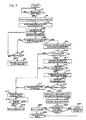
- the gateway hardware macro portion 17 Upon receiving the frame data (YES at step S1 in FIG. 7 and A: Receive in FIG. 8), the gateway hardware macro portion 17 outputs such received frame data to the CAN interface 8 (at step S2). The frame data is written into the receiving buffer 15 from the CAN interface 8 (at step S3).
- the CAN 9 inputs the frame data into the message box included in the CAN 9, the CAN 9 outputs an interrupt signal to the gateway controller 12.
- the search engine 11 identifies the interrupt signal as a trigger, retrieves the frame data from the message box, and stores the frame data in the receiving buffer 15.
- the search engine 11 acquires the CAN_ID, Data Link Control (DLC), and the data in synchronization with a search start pulse received from the receiving buffer 15 (at step S4). All the frame data stored in the receiving buffer 15 is considered to be the search target, and is input into the search engine 11.
- FIG. 9A shows a data structure of such received frame data.
- the frame data includes IDE (that represents the format type), RTR (that represents the frame type), a standard ID or extended ID, DLC, and the data.
- the standard ID or extended ID is referred to as CAN ID.
- the search engine 11 determines whether or not the received frame is the data that should be routed. This is shown as B (Target of Search) and C (Determination to be Identical) in FIG. 8.
- the search engine 11 acquires the CAN_ID, DLC, and the data from the frame data, and then searches the map memory 13 (at step S5).
- the search engine 11 determines whether or not the routing map stores the ID matched with the CAN_ID (at step S6). If there is no ID matched with the CAN_ID in the routing map (NO at step S6), the search engine 11 further determines whether or not it is a search end (at step S7).
- step S7 If it is not a search end (NO at step S7), the map memory 13 is searched again from step S5 to determine whether or not the ID matched with the CAN_ID is registered in the map memory. If it is a search end (YES at step S7), the data frame is discarded because the data is not a target to be relayed (at step S8).
- a SUM check of the routing map is carried out (at step S9 and E in FIG. 8). Firstly, calculated are the SUM values of the data, such as CAN_ID, the mask information, the destination channel, the transmission memory area FIFO number, and the data label, stored in the entry having the matched ID (at step S9), and then such calculated SUM values are compared with check values included in the routing map (at step S10).
- step S10 If the SUM value and the check value are different, it is determined there is a routing error (NO at step S10) and a SUM_ERR signal that indicates an error is output to the CPU 2 as an interrupt signal (at step S17). Subsequently, when the CPU 2 confirms this error (YES at step S18), an error flag is cleared (at step S19). All the frame data stored in the message boxes of the CAN 9 is considered to be the search target. Accordingly, referring to FIG. 10, the frame sent and received between nodes on a single channel is also stored in the message box. However, the search engine 11 discards the frame that does not have to be routed.
- the search engine 11 acquires a destination channel from the routing map (at step S13). After determining the destination channel, the search engine 11 checks whether the destination channel is valid or invalid. If the target channel is determined invalid (NO at step S12), an interrupt signal is output to the CPU 2 to notify that there is a routing error (at step S17). If the target channel is determined valid (YES at step S12), the data label is added to the frame data and the frame data is output to the transmission FIFO memory 21 (at step S13), as shown in FIG. 9B. If there is a contention between the channels, the frame data is temporarily stored in the temporary buffer 32.
- the frame data temporarily stored in the temporary buffer 32 is written into the transmission FIFO memory 21 by arbitration of a FIFO arbitration unit (first arbitration unit) 23, while the FIFO arbitration unit 23 is also arbitrating the frame output from another search engine 11 (at step S14).
- the FIFO arbitration unit (first arbitration unit) 23 will be described later in detail.
- the number of stages is set for the frame data that can be stored. If the frame data is forwarded to the transmission FIFO memory 21 with exceeding the number of stages, there is no longer an empty stage or area in the transmission FIFO memories 21.
- the search engine 11 determines that there is an overflow in any of the transmission FIFO memories 21, the search engine 11 outputs an interrupt signal of overflow error to the CPU 2 (at step S17). Subsequently, when the CPU 2 confirms the above-mentioned error (YES at step S18), the error flag is cleared (at step S19). The data label added to the frame data on the search engine 11 will be described later in detail.
- the frame data is written into the transmission FIFO memory 21 by means of the arbitration of the FIFO arbitration unit 23 and the message counter 22 starts counting up (at step S20). If the count value of the message counter 22 reaches a predetermined value (at step S21), the search engine 11 outputs an interrupt signal to the CPU 2. If the data forward is implemented by means of the control of the DMA controller 7 (YES at step S22), a data request signal (DREQ) is output to the DMA controller 7 (at step S23). The DMA controller 7 to which the signal is input transmits the data received from the transmission FIFO memory 21 (at step S25).
- the search engine 11 outputs a forwarding interrupt signal to the CPU 2 (at step S24).
- the CPU 2 implements a forwarding process of the frame data that has been routed on a software process by means of the program control (at step S25 and F in FIG. 8).
- the free run timer 5 counts the holding time from the time when the frame data is received and the routing process is performed on the search engine 11 to the time when the frame data is forwarded to a forwarding destination.
- the CPU 2 detects a delay of the frame data.
- FIG. 11 shows a configuration of the transmission FIFO memories 21.
- Each channel includes three 32-stage transmission FIFO memories 21.
- one stage of each FIFO memory 21 is capable of storing information equal to one frame.
- the number of stages of each FIFO memory 21 and the number of lines thereof are not limited to the structure shown in Fig. 11, but may be changed arbitrarily according to the number of frames, the number of channels, or the communication speed.
- the frame data buffered in the transmission FIFO memories 21 are counted by the respective message counters 22 and are then displayed.
- the count value on the message counter 22 represents the number of frames that are allowed to retrieve from the associated transmission FIFO memories 21. If the count value of the message counter 22 reaches the value set on the register 31, the search engine 11 outputs an interrupt signal to the CPU 2.
- the CPU 2 is capable of acquiring the frame equal in number to the count value, from the transmission FIFO memories 21.
- the CPU 2 reads the count values of the message counters 22 of all the corresponding FIFO memories 21 by means of the software process of the program control to detect which transmission FIFO memory 21 should be read and how many times the transmission FIFO memory 21 should be read.
- the oldest frame data is discarded from the FIFO memory 21 and the newest one is written into the transmission FIFO memory 21, as shown in FIG. 12.
- the frame data stored in the transmission FIFO memories 21 are written into the receiving buffer 15 by means of the software process of the program or by means of the forward control of the DMA controller 7. Also, a process that cannot be standardized as a gateway apparatus such as, for example, a fail process, the CAN_ID, data processing, or the like is also carried out by means of the software process.
- the software process is realized such that the CPU 2 reads the program stored in the ROM 3 and implements the process according to the program.
- FIG. 13 shows a configuration of the connection between the FIFO arbitration unit (first arbitration unit) 23 and the transmission FIFO memories 21.
- a FIFO counter controller 24 in FIG. 13 controls the message counter 22. If multiple pieces of frame data are simultaneously output from multiple search engines 11, the FIFO arbitration unit 23 outputs the frame data to the transmission FIFO memory 21, in accordance with a priority that has been set.
- FIG. 14 shows signals input/output in communication between the CANs 9, the CAN interface 8, the search engine 11, and the bus interface 10.
- IRQ 1 interrupt signal from the CAN_1
- WR 1 register write signal
- DATAxO register read signal
- DATAxI register write signal
- the similar signals are also output from the CAN_2 and the CAN_3.
- the CAN interface 8 outputs the STARTx (routing start signal), IDx, DLCx, DATAx, and EN (operation enable signal of the gateway controller 12) to the search engine 11.
- the search engine 11 When a given number of the frames are stored in the transmission FIFO memories 21, the search engine 11 outputs INTv (gateway interrupting signal) to the CPU 2.
- the CPU 2 outputs RDv (register reading signal) and WRv (register writing signal), and reads the count value of the message counter 22. Then, data writing or data reading is carried out with the use of DATAvO (register (that includes the transmission FIFO memory 21) reading data), DATA vI (register (that includes the transmission FIFO memory 21) writing data), or the like.
- BUSYv transmission FIFO memory 21 writing operation signal
- the data label carries no special significance in the hardware configuration of the gateway controller, and is not directly related to routing. However, the data label is added to the frame data and transferred, as shown in FIG. 9B.
- the data label is represented with eight bits.
- the data label is applied to the frame data at the time of routing process, and is forwarded to the transmission FIFO memory 21.
- the data label is acquired by means of the software process of the program control, and is used as a reference pointer for a frame information table stored in the ROM 3. This eliminates the necessity of searching the frame information by means of the software process again, thereby making it possible to shorten the time for a forwarding process by means of software.
- the check value is registered for the SUM check in the routing map, as shown in FIG. 8.
- Calculated are the SUM values of the data such as CAN_ID, the mask information, the destination channel, the transmission FIFO memory number, and the data label stored in the entry.
- Such calculated SUM value is compared with the check value stored in the routing map. If the values are different, it is considered that there is a routing error and a SUM_ERR signal is then output to the CPU 2.
- FIG. 15 shows a configuration of the gateway hardware macro portion 17.
- a routing portion 51, a selector 52, a register 56 are provided in former stages of the above-described search engine 11 and the transmission FIFO memories 21, as shown in FIG. 15.
- the routing portion 51 is provided for each communication channel as shown in FIG. 15, in such a manner that the frame data is obtained from the message box of the CAN 9 to implement a routing process on the frame data according to the forwarding destination thereof.
- the routing portion 51 refers to the destination information set on the frame data, and sets a forwarding destination of the frame data to any of a software controller 50, the selector 52, and both the software controller 50 and the selector 52.
- the software controller 50 is a functional component that is realized when the CPU 2 operates by means of the program control. In this manner, the forwarding destination is routed by a channel unit or by a frame unit that has been selected, thereby reducing the load processed by the search engine 11.
- the frame data to be transmitted to the software controller 50 can be forwarded by priority without using the search engine 11, thereby making the process start time earlier on the software controller 50. Furthermore, it is possible to implement the software process by the software controller 50 and the hardware process by the search engine 11 in parallel.
- the register 56 stores the setting information set by the software controller 50.
- the setting information includes at least operation setting information of the gateway apparatus and the setting information on routing.
- the routing portion 51 carries out the routing operation of the frame data in accordance with the setting information stored in the register 56. Only the routing portion 51 operates with reference to the setting information.
- the selector 52, the search engine 11, the transmission FIFO memories 21 arranged in the latter stage do not stop operating according to the setting information. For this reason, even if the gateway setting or the communication channel is dynamically changed, there is no problem that the frame data is lost in the gateway hardware macro portion 17.
- the search engine 11 and the transmission FIFO memories 21 are provided for each communication channel.
- one search engine 11 and one set of the transmission FIFO memories 21 are provided for multiple communication channels.
- one search engine 11 and one set of the transmission FIFO memories 21 may be provided for a given number of the communication channels, not shown.
- the selector 52 is provided in the former stage of the search engine 11. The selector 52 controls the timing when the data output from multiple communication channels is simultaneously input into the search engine 11. Even if multiple pieces of frame data are output from multiple communication channels simultaneously, the selector 52 controls the timing when the frame data is output to the search engine 11 according to the order of priority or an arrival sequence.
- the search engine 11 and the transmission FIFO memories 21 can be shared by the multiple communication channels.
- the routing portion 51 includes a first destination routing portion 59 and a second destination routing portion 60.
- the frame data is routed by a message routing portion 58 of the CAN 9 according to the data ID, and is registered in the message boxes (0, 1, 2, 3, ⁇ ).
- the first destination routing portion 59 sets the destinations of multiple pieces of frame data in the message boxes (0, 1, 2, 3, ...) that are routed by the message routing portion 58, to the software controller 50 or the search engine 11, or sets a multi-address transmission to send to both the software controller 50 and the search engine 11.
- the second destination routing portion 60 forces the frame data that is scheduled to send to the search engine 11 to change to send to the software controller 50, or to discard the frame data in accordance with the processing status of the search engine 11.
- the search engine 11 includes a state controller 70, an entry recognizing portion 71, a number adder 72, a number subtracter 73, a lower limit selector 74, an upper limit selector 75, an adder 76, a division and result holder 77, a table 78 in a memory, a match comparator 79, and an entry check portion 80.
- a frame output signal of the selector 52 is input into the state controller 70 to control the functional components shown in FIG. 17.
- the state controller 70 controls to implement the search of the table 78 a set number of times only, according to the number of search times input from the entry recognizing portion 71.
- the number of the nodes registered for each of the communication channels is different, in other words, the number of the entries is different. Therefore, as shown in FIG. 18A and FIG. 18B, each of the communication channels has a different size of the area to be used in the memory (table) 78 that stores the entry data.
- the entry data registers the information on the forwarding destination of the frame data that has been transferred from each channel. For this reason, an upper limit entry number, a lower limit entry number, and the number of search times are set for each of the receiving channel by the entry recognizing portion 71.
- FIG. 19 shows a configuration of the entry recognizing portion 71.
- the entry recognizing portion 71 includes a selecting portion 91, a first conversion table 92, and a second conversion table 93.
- Information on the channel that has received the data (hereinafter, referred to as received CH information) and the setting information for each channel are input into the selecting portion 91.
- the setting information includes a lower limit set value, an upper limit set value, and a set value of the number of valid entries.
- the lower limit set value denotes a lower limit value of the memory address assigned to the channel.
- the upper limit set value denotes an upper limit value of the memory address assigned to the channel.
- the set value of the number of valid entries denotes the number of the entries that have been registered for routing on the channel.
- the selecting portion 91 specifies the communication channel that has received the frame data with the use of the received CH information, outputs the set value of the number of valid entries of the channel to the first conversion table 92, and outputs the upper limit set value and the lower limit set value to the second conversion table 93.
- the first conversion table 92 calculates the number of search times that is set for the number of search times of the memory 78 with the set value of the number of valid entries. For example, if the number of entries of the channel is 256 entries (nodes), 256 equals two to the eighth power and the number of search times is therefore nine, after adding one to eight.
- the upper limit set value and the lower limit set value are input into the second conversion table 93, and an upper limit entry number and a lower limit entry number are output.
- the lower limit entry number is the smallest number among the IDs of the nodes registered on the channel.
- the upper limit entry number is the largest number among the IDs of the nodes registered on the channel.
- the lower limit entry number is output to the lower limit selector 74, and the upper limit entry number is output to the upper limit selector 75.
- the number of search times is output to the state controller 70.
- the lower limit entry number is input into the lower limit selector 74 from the entry recognizing portion 71.
- the lower limit selector 74 selectively outputs any one of the entry numbers where one has been respectively added to the lower limit entry number, the entry number of the last time, and the output from the division and result holder 77, according to the control of the state controller 70.
- the upper limit entry number is input into the upper limit selector 75 from the entry recognizing portion 71.
- the upper limit selector 75 selectively outputs any one of the entry numbers where one has been respectively subtracted from the lower limit entry number, the entry number of the last time, and the output from the division and result holder 77, according to the control of the state controller 70.
- the adder 76 adds the entry number of the upper limit selector 74 and the entry number of the lower limit selector 75.
- the division and result holder 77 divides the added value of the adder 76 by two, and holds the division result.
- FIG. 20 schematically shows the method of the binary search.
- N is a lower limit set value of the memory used by the channel of a search target
- M is an upper limit set value thereof.
- the set value of the number of valid entries is set to the upper limit set value and zero is set to the lower limit set value, for ease of explanation.
- an intermediate value of the upper limit set value and the lower limit set value is calculated. In other words, (N + M) / 2 is obtained as C1.
- the entry data of the address of C1 is compared with the ID of the received data.
- the entry data of the search target is considered to be included in a larger half of the memory address.
- the lower limit selector 74 selects a value where one is added to the previous value of C1 retained on the division and result holder 77.
- the upper limit selector 75 still selects the previous value of M.
- the state controller 70 controls the above-mentioned operation. The values are added on the adder 76 and then are divided by two on the division and result holder 77. As a result, (C1 + 1 + M) / 2 is obtained as C2.
- Such calculated entry data and the received ID are compared, and the next address is sequentially generated.
- the entry data that matches the ID of the received data can be searched from the data in the memory 78.
- the entry check portion 80 checks whether or not the entry data read out of the table 78 is normal. The check result is output to the state controller 70.
- the match comparator 79 compares the entry data read out of the table 78 and the ID of the received data.
- FIG. 21 shows a configuration of the match comparator 79.
- the match comparator 79 includes a logic operation portion 95 and a match comparison operation portion 96.
- the logic operation portion 95 masks the ID of the received data to limit the scope of search.
- the match comparator 79 compares the masked ID and the entry data that has been read to determine whether both are matched.
- the address of the memory (table) 78 can be configured by setting the higher-order bits to represent the received channel number and setting the lower bits to represent the address of a pointer.
- the state controller 70 firstly sets the number of search times to zero (at step S31).
- the number of the entries of the channel is obtained from the received CH information on the entry recognizing portion 71, and a number value of search times is predetermined and set according to the number of the entries (at step S32). Such predetermined number value of search times is notified to the state controller 70 from the entry recognizing portion 71.
- the state controller 70 compares the number of search times and the predetermined number value of search times notified by the entry recognizing portion 71 (at step S33). If the number of search times is smaller than the predetermined number value of search times (YES at step S33), a pointer address of the memory is created on the basis of an initial value or information of a number magnitude comparison of the previous time (at step S34).
- the lower limit entry number is input into the lower limit selector 74 from the entry recognizing portion 71.
- the upper limit entry number is input into the upper limit selector 75 from the entry recognizing portion 71.
- the adder 76 adds the lower limit entry number and the upper limit entry number.
- the division and result holder 77 divides such added value by two and holds the result. This result serves as the pointer address.
- the entry data indicated by the pointer address is read out of the memory 78 (at step S35). Then, such read entry data is input into the entry check portion 80, and is checked whether or not the data is normal. If the data is not normal (NO at step S36), it is processed as a system error (at step S41). If the data is normal (YES at step S36), the match comparator 79 determines whether or not the ID of the received data matches the entry data. If both are not matched (NO at step S37), the number of search times is incremented by one, the number magnitude comparison on the match comparator 79 is output to the state controller 70 (at step S38), and repeats the process from step S33.
- the state controller 70 controls the lower limit selector 74 and the upper limit selector 73, according to the magnitude comparison result, and the pointer address is generated according to the comparison result of the previous time. If both are matched (YES at step S37), the destination information of such matched entry data is checked (at step S39). If the destination information is normal, the destination information of the entry data is written into the transmission FIFO memory 21 (at step S40). If the destination information is not normal (NO at step S39), it is processed as a system error (at step S41). If the number of search times is greater than the predetermined number value of search times (YES at step S33), such received frame data is discarded (at step S42).
- the state controller 70 carries out a normality check operation of the map information, while the frame data is not being received in an idle period. Referring to a flowchart in FIG. 25, the normality check operation is described.
- the state controller 70 implements an independent self checking (at step S64), while the frame data is not being received in an idle period (at step S51).
- the state controller 70 creates the pointer address (at step S66), and searches and acquires the entry data stored in the corresponding address (at step S66). Then, it is determined whether or not such acquired entry data is normal (at step S67). If it is determined that such acquired entry data is normal (YES at step S67), the process is completed. If an error is detected (NO at step S67), a system error is processed (at step S68).
- a parallel buffer (second storage portion) 53 is additionally provided, so the frame data output from the search engine 11 is stored in the transmission FIFO memory 21 and the frame data is also transferred to store in the parallel buffer 53.
- the data stored in the parallel buffer 53 is read by the software controller 50.
- the frame data is stored in the transmission FIFO memory 21 and then the software controller 50 reads the frame data out of the transmission FIFO memory 21.
- the frame data having a high priority is also stored in the parallel buffer 53 and the software controller 50 retrieves the frame data from the parallel buffer 53. This eliminates the waiting time.
- the parallel buffer 53 can not only store the frame data having a high priority but also store all the data.
- the parallel buffer 53 is capable of virtually mapping the result of the frame specification (determination) on a storage location (entry). This can reduce the load of the determination process implemented on the CPU 2.
- an arbitration unit (second arbitration unit) 54 is provided in the latter stage of the transmission FIFO memories 21.
- One arbitration unit 54 is provided for each communication channel.
- the arbitration unit 54 has functionalities of adjusting the timing of writing into the message box of the CAN 9, when the frame data output from the transmission FIFO memory 21 overlaps the frame data output from the software controller 50. With the above-mentioned arbitration unit 54, the frame data can be transmitted by the gateway hardware macro portion 17 only without using the software controller 50.
- FIG. 28 shows a flow of the frame data when the frame data is forwarded only by the software control of the CPU 2.
- FIG. 29 shows a data flow of the frame data in accordance with the first embodiment of the present invention.
- the frame data is routed on the hardware.
- the software control is needed for transmitting such routed frame data.
- the frame data can be routed and forwarded by the gateway hardware macro portion 17 only. Furthermore, according to the need, the frame data stored in the gateway hardware macro portion 17 is passed on to the CPU 2.
- the gateway hardware macro portion 17 Upon receiving the frame data (YES at step S71), the gateway hardware macro portion 17 routes the frame data on the routing portion 51 (at step S72). As described, the routing portion 51 determines the destination with the use of the ID set at the frame data, and sets whether the frame data should be output to the software controller 50 or to the search engine 11. The frame data is output to either or the software controller 50 or the search engine 11 or to both thereof, according to the setting.
- the selector 52 When the selector 52 retrieves the frame data from the routing portion 51, the selector 52 outputs the data to the search engine 11 (at step S73).
- the search engine 11 searches for the forwarding destination of such retrieved frame data (at step S74), and stores the frame data in the transmission FIFO memory 21 and in the parallel buffer 53 (at step S75).
- the frame data stored in the parallel buffer 53 is read by the software controller 50 (at step S76).
- the arbitration unit 54 arbitrates the frame data output from the software controller 50 and the frame data retrieved from the transmission FIFO memory 21 (at step S77) to write into the message box.
- the frame data written into the message box of the CAN 9 on each communication channel is read out to output to the bus of each channel (at step S78).
- the map information used on the search engine 11 can be statically or dynamically changed according to the state of the vehicle.
- a state management portion 100 is provided for changing the map information to be read out of the map memory 13, according to the state of the vehicle.
- the state management portion 100 retrieves the map information at the initialization from the map memory 13.
- the map information at the time of adding the number of the channels is loaded from the map memory 13.
- the map information at the time of entry addition and modification is loaded from the map memory 13.
- Such loaded map information is checked on the state management portion 100 whether or not it is normal, and is stored in the table (memory) 78 of the search engine 11.
- the state management portion 100 selects a map in accordance with the state of the vehicle (at step S81). Such selected map information is retrieved on a channel basis (at step S82), and checks the normality of the map information (at step S83). If there is an error in normality determination (YES at step S84), it is processed as a system error (at step S89). If the number of pieces of map information in which the normality has been checked reaches the number of the valid channels (YES at step S85), the normality is further checked on the whole map (at step S86). If there is also an error (YES at step S87), it is processed as a system error (at step S89). When the normality check is completed (NO at step S87), such selected map information is stored in the table 78 and the data is replaced (at step S88).
- a format converter 55 may be provided as shown in FIG. 34 and FIG. 35.
- the format converter 55 converts the frame data to have a format that can be recognized on the destination node.
- the format conversion may be performed for the frame data retrieved from the transmission FIFO memory 21.
- the format conversion may be performed for the frame data before the frame data is stored in the transmission FIFO memory 21.
- a state monitoring block 200 may be provided for monitoring whether or not there is a piece of the frame data in each block.
- the state monitoring block 200 may operate only the transmission FIFO memory 21 that includes the frame data to be processed. Alternatively, only a functional block that is supposed to receive the frame data may be operated. This makes it possible to reduce the power consumption on the gateway apparatus.
- the data label As usage of the data label applied to the frame data, in the first embodiment, the data label has been described as a reference pointer of the frame information table. In addition, there is a following usage.
- the data label having eight bits is divided into two bits respectively, as shown in FIG. 37. Four two bits respectively represent a thinning out pattern that represents a cyclic timing of thinned out transmission, an ID conversion that represents a pattern for ID conversion, a data label pattern that represents a pattern for data conversion, and a patter that represents a holding time.
- the afore-mentioned data labels are applied to the frame data so that the CPU 2 controls according to the data label so as to implement the data process, forwarding process, and fail safe process.
- the data label is described to have eight bits. However, the number of bits to be applied to the frame data as a data label is not limited to eight bits.
- the present invention includes a gateway apparatus that controls a forwarding process of frame data between multiple communication channels, the gateway apparatus including: a search engine that is respectively provided for each of the multiple communication channels to route the frame data between the multiple communication channels; and a first storage portion that is respectively provided for each of the multiple communication channels to temporarily store the frame data routed.
- the search engines may be implemented by hardware.
- the routing process by means of software creates a holding time in the routing process, when the application other than the routing process has a greater load.
- the routing process implemented by means of hardware does not create the holding time.
- the search engine respectively provided for each of the multiple communication channels may be provided with a routing map used for a channel selection of the frame data. It is therefore possible for each search engine to implement the routing process independently.
- the search engine may include an address generator that generates an address in the routing map; a routing map portion that obtains routing information of the address from the routing map; and a comparator that compares a first ID included in the routing information obtained from the routing map and a second ID included in the frame data, obtains a forwarding destination communication channel from the routing map when the first ID matches the second ID. It is possible to construct the search engine with a simple hardware apparatus.
- the search engine may discard the frame data having a format that is not registered in the routing map. It is possible to prevent unnecessary frame data from forwarding.
- the first storage portion may include multiple FIFO memories having multiple stages.
- the first storage portion may be provided with multiple FIFO memories, thereby enabling multiple pieces of frame data to store sequentially.
- the above-mentioned gateway apparatus may include a controller that forwards the frame data routed and stored in the first storage portion to a forwarding destination communication channel. It is possible to transmit the frame data routed to a forwarding destination.
- the above-mentioned gateway apparatus may include a DMA controller that forwards the frame data routed and stored in the first storage portion to a forwarding destination communication channel. It is possible to transmit the frame data that routed to a forwarding destination.
- the above-mentioned gateway apparatus may include a counter portion that counts the number of pieces of frame data stored in the first storage portion. Accordingly, it is possible to count and display the number of pieces of frame data stored in the first storage portion. In addition, it is easy to learn the storage state of the first storage portion, for example, whether or not the first storage portion is full of the frame data. Furthermore, it is possible to secure the number of the frames that can be retrieved from the first storage portion.
- the search engine may output an interrupt signal to a controller that controls the gateway apparatus, when the number of pieces of frame data counted by the counter portion reaches a given number. Notification is made that a given number of pieces of frame data is stored in the first storage portion, so that the next process such as a transmission process can be implemented.
- the above-mentioned gateway apparatus may include a first arbitration unit that arbitrates the multiple communication channels, when the frame data routed by the search engine is stored in the first storage portion.
- the first arbitration unit arbitrates the frames output from the multiple search engines, thereby allowing the search engine to output the frame data without considering the output timing of the frame data routed.
- the first arbitration unit may include a register in which a priority is set for each of the multiple communication channels; and the frame data is written into the first storage portion according to the priority, when multiple pieces of frame data are simultaneously written into the first storage portion. It is therefore possible to store the frame data of the communication channel in the first storage portion on a priority basis.
- the search engine may apply an additional piece of data that represents a recorded position of the frame data necessary for forwarding the frame data. Accordingly, the controller is capable of retrieving the information necessary for transmission, with reference to the additional piece of data.
- the search engine may output an interrupt signal to a controller that controls the gateway apparatus, when there is a routing error at the time of routing the frame data. It is possible to notify an error caused during routing to the controller.
- the search engine implements an error check of the routing map, when the search engine determines that the frame data should be routed by searching the routing map. It is therefore possible to prevent the routing error.
- the above-mentioned gateway apparatus may include a register that sets validity or invalidity of the first storage portion provided for each of the multiple communication channels. Multiple first storage portions are provided in advance, and one or more first storage portions that have been invalid are made valid to deal with the increase of the communication channels. This makes it possible to correspond to the number of the communication channels.
- the search engine may determine an overflow of the first storage portion, when the frame data is transferred to the first storage portion and exceeds the number of pieces of frame data that can be stored in the first storage portion, and outputs an interrupt signal that notifies an error to a controller that controls the gateway apparatus. Overflow in the first storage portion is detected, and the data loss can be detected.
- the above-mentioned gateway apparatus may include a timer that counts a period from when the frame data routed is received to when the frame data is forwarded to a forwarding destination communication channel, wherein a controller that controls the gateway apparatus detects a holding time of the frame data with the use of the period counted by the timer. This makes it possible to implement a failsafe process by detecting a holding time of the frame data and discarding the old data.
- the search engine may determine a routing error, when there is no forwarding destination communication channel to which the frame data is forwarded, when a forwarding destination communication channel is invalid, when there is no first storage portion in which the frame data is to be stored, or when the first storage portion is invalid, and outputs an interrupt signal that notifies an error to a controller that controls the gateway apparatus. Accordingly, it is possible to detect the routing error on the gateway apparatus.
- the present invention also includes a gateway apparatus that controls a forwarding process of frame data between multiple communication channels, the gateway apparatus including: a routing portion that routes the frame data on the basis whether the frame data is processed on a controller that employs a program control or the frame data is processed on hardware; a search engine that routes the frame data to be processed on hardware on the basis of a forwarding destination; and a first storage portion that temporarily stores the frame data routed.
- the above-mentioned gateway apparatus may further include a selector that adjusts timings when multiple pieces of frame data forwarded from the multiple communication channels are input into the search engines. It is therefore possible for multiple communication channels to share the search engine and the first storage portion.
- one search engine and one storage portion may be provided for the multiple communication channels.
- the above-mentioned gateway apparatus may further include a second storage portion separately provided from the first storage portion to store the frame data routed by the search engine.
- the search engine stores the frame data having a high priority in the second storage portion; and the controller acquires the frame data having the high priority from the second storage portion. Accordingly, the data having a high priority can be forwarded to the controller on a priority basis, reducing the holding time of the process on the controller.
- the controller may refer to a data label applied to the frame data to implement a data process, a forwarding process, and a fail safe process. Accordingly, it is possible to control the data process, the forwarding process, and the fail safe process and to utilize the data label effectively.
- the above-mentioned gateway apparatus may further include a second arbitration unit that arbitrates first frame data read out of the first storage portion and second frame data output from the controller, when the first frame data and the second frame data are stored in a buffer provided for each forwarding destination. It is therefore possible to implement the forwarding process on the hardware.
- the above-mentioned gateway apparatus may further include a protocol converter that implements a protocol conversion of first frame data before stored in the first storage portion and second frame data retrieved from the first storage portion. This enables the frame data to forward, even if the protocols are different on the node of the forwarding source and that of the forwarding destination.
- the above-mentioned gateway apparatus may further include a register that stores at least operation setting information of the gateway apparatus and routing setting information.
- the routing portion may operate according to the operation setting information and the routing setting information. Only the routing portion operates according to the setting information. Accordingly, the search engine or the first storage portion is not stopped during the process, and the frame data routed by the routing portion can be stored in the first storage portion without fail. This does not produce the loss in the frame data.
- the search engine may implement a validity check of map information for routing while searching for the map information or idling. It is therefore possible to confirm the validity of the map information.
- the search engine includes multiple pieces of map information for routing; and the map information is changed according to a state of a control target. This makes it possible to use the map information according to the state of a control target.
- the search engine may retrieve only data necessary for each of the multiple communication channels at the time of retrieving the map information from a memory. Accordingly, only a necessary portion of the data can be renewed.
- the search engine may implement an error check of the data retrieved at the time of retrieving the map information from the memory. It is therefore possible to detect an error in the map information.
- the number of entries may be changed according to a forward control function of the gateway apparatus, the entries being respectively provided for the multiple communication channels and registered as the map information.
- the gateway apparatus may further include a state monitoring block that selectively operates at least the routing portion and the first storage portion according to a state of a forward control function. Accordingly, it is possible to operate only a functional portion necessary for a forwarding control, thereby reducing the power consumption.
- the search engine may mask an ID number of the frame data at the time of retrieving entry data having a forwarding destination of the frame data received from map information, and detects the entry data of a corresponding communication channel. This makes it possible to shorten the period for searching for the target entry data.
- the present invention is based on Japanese Patent Application No. 2005-133443 filed on April 28, 2005 and Japanese Patent Application No. 2006-013230 filed on January 20, 2006 , the entire disclosure of which is hereby incorporated by reference.
Abstract
Description
- This invention generally relates to a gateway apparatus mounted on a vehicle and a routing method that relay data between communication networks.
- In these years, multiple electronic control units (ECUs) are mounted on a vehicle. Referring to FIG. 38, there are provided, for example, an engine ECU, a door control ECU, an air bag ECU, an audio ECU, and a navigation ECU. A gateway apparatus is necessary for routing data so that the ECUs communicate with each other via LANs having different communication protocol and different bit rates.
Japanese Patent Application Publication No. 2003-244187 Japanese Patent Application Publication No. 2003-264571 - The gateway apparatus relays data that are sent and received on multiple different network systems, and realizes gateway functions such as a communication protocol conversion and packet filtering. This allows the nodes connected to different network systems to communicate with each other.
- The gateway apparatuses disclosed in
Document 1 andDocument 2, however, have the gateway functions implemented by software. Therefore, as the ECUs are occupied by application other than routing at a high ratio, relay processing is delayed. - In addition, an increased number of channels makes it complicated to search for a channel via which the data is relayed, and needs a longer time for routing. Furthermore, an increased number of frames to be managed needs a longer time to process various information for routing, and increases the waiting time on the gateway apparatus. This degrades throughput. There is another problem that a buffer structure becomes complex so as to suppress frame loss on the gateway apparatus.
- The present invention has been made in view of the above circumstances and provides a gateway apparatus and routing method that improves the routing efficiency.
- According to one aspect of the present invention, preferably, there is provided a gateway apparatus that controls a forwarding process of frame data between multiple communication channels. The gateway apparatus includes: a search engine that is respectively provided for each of the multiple communication channels to route the frame data between the multiple communication channels; and a first storage portion that is respectively provided for each of the multiple communication channels to temporarily stores the frame data routed. In accordance with the present invention, the search engine and the first storage portion are respectively provided for each of the multiple communication channels, thereby enabling the routing process in parallel. This does not increase the period necessary for the routing operation, even when the gateway apparatus has multiple communication channels.
- According to another aspect of the present invention, preferably, there is provided a gateway apparatus that controls a forwarding process of frame data between multiple communication channels, the gateway apparatus including: a routing portion that routes the frame data on the basis whether the frame data is processed on a controller that employs a program control or the frame data is processed on hardware; a search engine that routes the frame data to be processed on hardware on the basis of a forwarding destination; and a first storage portion that temporarily stores the frame data routed. In accordance with the present invention, it is possible to reduce the processing load on the search engine, by providing the routing portion to route the frame data to the forwarding destination. It is also possible to forward the frame data that should be forwarded to the controller in advance on a priority basis, thereby making the process start time earlier. Such provided routing portion enables the software process by the controller and the hardware process by the search engine to implement in parallel.
- According to yet another aspect of the present invention, preferably, there is provided a routing method that controls a forwarding process of frame data between multiple communication channels, the routing method including: routing the frame data received for each of the multiple communication channels independently; and storing the frame data routed in a first storage portion provided for each of the multiple communication channels. In according with the present invention, the frame data retrieved is routed independently on a communication channel basis. This does not increase the time for the routing process, even if multiple communication channels are provided.
- According to still another aspect of the present invention, preferably, there is provided a routing method that controls a forwarding process of frame data between multiple communication channels, the routing method including: routing the frame data on the basis whether the frame data is processed on a controller that employs a program control or the frame data is processed on hardware; routing the frame data to be processed on hardware on the basis of a forwarding destination; and temporarily storing the frame data routed.
- For a better understanding of the present invention, and to show how the same may be carried into the effect, reference will now be made, by way of example to the accompanying drawings in which:
- FIG. 1 shows a configuration of a gateway apparatus used in accordance with a first embodiment of the present invention;
- FIG. 2 shows a configuration of a gateway controller in accordance with the first embodiment of the present invention;
- FIG. 3 shows a configuration of a search engine in accordance with the first embodiment of the present invention;
- FIG. 4 shows an example of a routing map stored in a map memory in accordance with the first embodiment of the present invention;
- FIG. 5 shows a configuration of a search controller in accordance with the first embodiment of the present invention;
- FIG. 6 is a time chart showing an operation timing of the search controller in accordance with the first embodiment of the present invention;
- FIG. 7 is a flowchart showing an operation timing of the search controller in accordance with the first embodiment of the present invention;
- FIG. 8 conceptually shows an operation of a search controller in accordance with the first embodiment of the present invention;
- FIG. 9A and FIG. 9B show a data structure of frame data in accordance with the first embodiment of the present invention;
- FIG. 10 conceptually shows an operation of the search engine in accordance with the first embodiment of the present invention;
- FIG. 11 shows a configuration of transmission FIFO memories on one channel in accordance with the first embodiment of the present invention;
- FIG. 12 shows a process when the transmission FIFO memories are overflowed in accordance with the first embodiment of the present invention;
- FIG. 13 shows a configuration of a transmission FIFO memory unit in accordance with the first embodiment of the present invention;
- FIG. 14 shows signals input/output in communication among CANs, a CAN interface, the search engine, and a bus interface in accordance with the first embodiment of the present invention;
- FIG. 15 shows a configuration of a gateway hardware macro portion in accordance with a second embodiment of the present invention;
- FIG. 16 is a block diagram showing a configuration of a routing portion in accordance with the second embodiment of the present invention;
- FIG. 17 is a block diagram showing a configuration of the search engine in accordance with the second embodiment of the present invention;
- FIG. 18A through FIG. 18C show use areas in a memory on each channel in accordance with the second embodiment of the present invention;
- FIG. 19 shows a configuration of an entry recognizing portion in accordance with the second embodiment of the present invention;
- FIG. 20 schematically shows the method of the binary search in accordance with the second embodiment of the present invention;
- FIG. 21 shows a configuration of a match comparator in accordance with the second embodiment of the present invention;
- FIG. 22 shows a masking process in accordance with the second embodiment of the present invention;
- FIG. 23A and FIG. 23B show the masking process in accordance with the second embodiment of the present invention;
- FIG. 24 is a flowchart showing a process procedure of the search engine in accordance with the second embodiment of the present invention;
- FIG. 25 is a flowchart showing a process procedure of the search engine, in particular, a procedure for an independent self checking in accordance with the second embodiment of the present invention;
- FIG. 26 shows another configuration of the search engine in accordance with the second embodiment of the present invention;
- FIG. 27 shows a configuration of the gateway hardware macro portion used in accordance with a third embodiment of the present invention;
- FIG. 28 shows a flow of the frame data when the frame data is forwarded only by the software control of the CPU;
- FIG. 29 shows a data flow of the frame data in accordance with the first embodiment of the present invention;
- FIG. 30 shows a data flow of the frame data in accordance with the third embodiment of the present invention;
- FIG. 31 is a flowchart showing a process procedure in accordance with the third embodiment of the present invention;
- FIG. 32 shows a state management portion in accordance with the third embodiment of the present invention;
- FIG. 33 is a flowchart showing a process procedure of the state management portion in accordance with the third embodiment of the present invention;
- FIG. 34 shows another configuration of the gateway hardware macro portion used in accordance with the present invention;
- FIG. 35 shows yet another configuration of the gateway hardware macro portion used in accordance with the present invention;
- FIG. 36 shows still another configuration of the gateway hardware macro portion used in accordance with the present invention;
- FIG. 37 shows an example of a data label in accordance with the present invention; and
- FIG. 38 is a view showing a connection state in which multiple ECUs and an in-vehicle gateway apparatus of the conventional art.
- Firstly, referring to FIG. 1, a first embodiment of the present invention will be described. FIG. 1 shows a configuration of a gateway apparatus employed in accordance with the first embodiment of the present invention. The first embodiment an in-vehicle gateway apparatus, in which communications take place using a Controller Area network (CAN) protocol. An in-
vehicle gateway apparatus 1 has aCPU 2 serving as a controller. TheCPU 2 is connected with a flash read only memory (ROM) 3, a universal asynchronous receiver transmitter (UART) 4, afree run timer 5, an interruption controller 6, aDMA controller 7, aCAN interface 8,multiple CANs 9, and abus interface 10. The structure shown in Fig. 1 has four CANs, namely, CAN_0, CAN_1, CAN_2, and CAN_3. However, an arbitrary number of CANs may be used. Thebus interface 10 is connected with asearch engine 11, atransmission buffer 14, and a receivingbuffer 15. Thesearch engine 11 includes amap memory 13 and agateway controller 12. Thesearch engine 11, thetransmission buffer 14, and the receivingbuffer 15 are connected by a data line, which carries data supplied to and from aCPU bus 16 via thebus interface 10. Thesearch engine 11 and thetransmission buffer 14 are connected by another data line. Thesearch engine 11 and the receivingbuffer 15 are connected by yet another data line. The receivingbuffer 15 is connected with theCAN interface 8 by a further data line so that data can be directly applied to the receivingbuffer 15 from theCAN interface 8. FIG. 1 also shows control lines that send and receive control signals, in addition to the above-mentioned data lines. TheCPU 2 outputs signals that control the above-described functional components onto the control lines. Another control line is provided between theDMA controller 7 and thegateway controller 12 so that theDMA controller 7 reads the data out of thegateway controller 12 and transfers such read data to a forwarding destination, without the control of theCPU 2. Hereinafter, a gateway hardwaremacro portion 17 denotes a configuration that includes thesearch engine 11, themap memory 13, hetransmission buffer 14, the receivingbuffer 15, thebus interface 10, and theCAN interface 8. - The gateway hardware
macro portion 17 is mainly provided with the functions described below. Firstly, when the gateway hardwaremacro portion 17 is booted and the in-vehicle gateway apparatus 1 is reset, the gateway hardwaremacro portion 17 transfers a routing map, as will be described later in detail. A register, not shown, stores information on whether or not the routing map is normally transferred. As soon as the routing map transfer is completed, the gateway hardwaremacro portion 17 implements a verification process, that is, checks whether or not there has been an error at the time of writing the routing map. If there is an error, a rest operation is implemented to transfer the routing map again. Secondly, to receive the frame data, the gateway hardwaremacro portion 17 identifies an interrupt signal as a trigger, and then retrieves the frame data from a message box of theCAN 9. Thirdly, the gateway hardwaremacro portion 17 performs a routing process of such received data. Fourthly, the gateway hardwaremacro portion 17 detects an error such as a routing error or the like. In addition to the above-described functions, the gateway hardwaremacro portion 17 may be provided with a forwarding function of the data after the routing process. - The
flash ROM 3 stores data or program to be used when theCPU 2 implements various processes that include a data transmission process. TheCPU 2 controls the whole in-vehicle gateway apparatus 1 shown in FIG. 1, and implements a forwarding process of the frame data routed by thegateway controller 12, by means of the program control. - The
UART 4 is connected to an external device, and converts a parallel signal sent from the external device into a serial signal. TheUART 4 also converts the serial signal sent from a serial device into the parallel signal. Thefree run timer 5 is a timer (counter) and repeats counting up, while receiving clock signals. Thefree run timer 5 counts a holding time from the time when the frame data is received and the routing process is performed on thegateway controller 12 to the time when the frame data is forwarded to a forwarding destination, so as to detect a delay of the frame data. - The interruption controller 6 controls an output of the interrupt signal to the
CPU 2, the interrupt signal having been output from thesearch engine 11. Thegateway controller 12 outputs an interrupt signal to theCPU 2, when a predetermined number of frames are stored in the transmission FIFO memories (first storage portion) 21, when thetransmission FIFO memories 21 are overflowed, or when a routing error occurs on thesearch engine 11. TheDMA controller 7 performs a DMA transfer of the frame data stored in thetransmission FIFO memories 21, by means of the routing process of thesearch engine 11, without involving theCPU 2. - Multiple CANs 9 (CAN_0, CAN_1, CAN_2, and CAN_3) are respectively provided for communication channels to store the frame data received from a CAN bus, not shown, or stores the frame data after the routing process is implemented on the
gateway controller 12. The frame data is routed and read out of the message box, and is output to the CAN bus. Upon receiving the frame data from the communication channel, theCAN 9 outputs an interrupt signal to thegateway controller 12 of thesearch engine 11. - The
search engine 11 identifies an interrupt signal output from theCAN 9 as a trigger, acquires the frame data from the message box of theCAN 9, and temporarily stores the frame data in the receivingbuffer 15 via theCAN interface 8. Thesearch engine 11 retrieves the frame data from the receivingbuffer 15 at a given clock timing, implements processes such as the routing process, an information search process of a destination to which the frame data is relayed to, and the like. Thegateway controller 12 is implemented by hardware. The routing map stored in themap memory 13 will be described later in detail. - The frame data that has been routed by the
gateway controller 12 is stored in thetransmission buffer 14. The frame data that has been read from the message box of theCAN 9 is stored in the receivingbuffer 15. - Referring now to FIG. 2, the gateway hardware
macro portion 17 is described. The gateway hardwaremacro portion 17 includes thesearch engine 11 and a transmissionFIFO memory unit 20. The transmissionFIFO memory unit 20 includes thetransmission FIFO memories 21 and amessage counter 22. The transmissionFIFO memory unit 20 is provided in thetransmission buffer 14. As shown in FIG. 2, each of thesearch engines 11 is provided for a respective one of the receiving channels. Threetransmission FIFO memories 21 and three message counters 22 are provided for each channel. In accordance with the present embodiment, the threeFIFO memories 21 are exclusively used for normal transmission, priority transmission, and determination processing, respectively, according to the functionalities thereof. Thetransmission FIFO memory 21 dedicated to the determination processing is used for processing the ID or data or checking the content of the data. - The
search engine 11 acquires the frame data from the message box of the associatedCAN 9, and stores such acquired frame data in the receivingbuffer 15, as shown in FIG. 2. Then, thesearch engine 11 reads the frame data out of the receivingbuffer 15 at a given timing for routing, and stores such routed frame data in thetransmission FIFO memory 21. One message box is provided for receiving in eachCAN 9, and other message boxes can be used arbitrarily, as shown in FIG. 2. - Now, referring to FIG. 3, a configuration of the
search engine 11 is described. Thesearch engine 11 includes asearch controller 30, themap memory 13, aregister 31, and atemporary buffer 32. Thesearch controller 30, theregister 31, and thetemporary buffer 32 correspond to thegateway controller 12 shown in FIG. 1. FIG. 3 shows only onesearch engine 11 and one transmissionFIFO memory unit 20. However, there are actually providedmultiple search engines 11 and transmissionFIFO memory units 20, as shown in FIG. 2. - The
search controller 30 operates as a functional component that implements the routing process of the frame data. Thesearch controller 30 retrieves the frame data stored in the receivingbuffer 15 at a given timing, and implements the routing process on the frame data. FIG. 3 shows the data to be loaded to thesearch controller 30. CAN_ID, DLC, CAN-DATA are loaded to thesearch controller 30. Themap memory 13 has a routing map that is used by thesearch controller 30 for routing. The routing map is defined for each channel that forwards the data, and the information of the routing map is defined in such a manner that the data received on each channel is forwarded to one or more different channels. FIG. 4 shows an example of the routing map. Each entry of the routing map has a memory address that stores the information, an IDE that represents the format type, an RTR that represents the frame type, an ID, mask information, channel information, a transmission FIFO memory No., and a data label as another piece of information. - The
temporary buffer 32 temporarily stores the frame that has been routed to the forwarding destination by thesearch controller 30. The setting information of thesearch controller 30 is stored in theregister 31. TheCPU 2 sets the setting information. For example, thetemporary buffer 32 stores information that designates suspension, start, and reset of functions of thesearch controller 30, information that sets validity and invalidity of thesearch controller 30 for each channel, definition information of a routing error shown in Table 1, information that sets whether or not a source of trouble should be notified to theCPU 2, if there is an overflow error or a routing error in thetransmission FIFO memories 21. Here, the overflow error in thetransmission FIFO memories 21 denotes that new data is written into a corresponding one of thetransmission FIFO memories 21 in a state where there is no available space in the involvedtransmission FIFO memory 21, and the newest data is overwritten into the oldest stage thereof. The routing error denotes that the frame data cannot be written into the correspondingtransmission FIFO memory 21 that is set as a forwarding destination, because thetransmission FIFO memory 21 is set invalid.[Table 1] Phenomenon Operation of Gateway Controller Notification to CPU Designation channel is not specified (all bits: 0) Discard frame Yes Designation channel set as invalid is specified Nothing No Transmission FIFO memory is not specified (all bits: 0) Discard frame Discard frame Yes Yes Specified transmission FIFO memory is set as invalid Discard frame Yes 1 is specified to set at reserved bit of destination channel Ignore any specification for reserved bit No 1 is set at reserved bit of transmission FIFO memory Ignore any specification for reserved bit No Bit is overlapped between ID and mask information Nothing No Multiple transmission FIFO memories are specified (two or more bits: 1) Forward to specified and lowermost bit No Bus is off Nothing No SUM error Nothing Yes - Now, referring to FIG. 5, a configuration of the
search controller 30 is described. Thesearch controller 30 includes functional components of anaddress generator 35, a map memory I/F portion (routing map portion) 36, and adata comparator 37. Theaddress generator 35 includes an address counter to sequentially generate an address in themap memory 13. The map memory I/F portion 36 serves as an interface with themap memory 13 to read the address data that has been generated by theaddress generator 35 from themap memory 13 and output to thedata comparator 37. Thedata comparator 37 compares to determine whether or not there is an address, registered in the routing map of themap memory 13, which corresponds to the data (CAN_ID) loaded from the receivingbuffer 15. - Referring to a timing chart shown in FIG. 6, an operation timing of the
search controller 30 is described. When the received data of theCAN 9 is stored in the receivingbuffer 15, a search start pulse is applied to theaddress generator 35 from the receivingbuffer 15. Theaddress generator 35 identifies the search start pulse as a trigger, and sequentially generates the addresses in themap memory 13. The addresses are shown in FIG. 6 as map addresses 0, 1, 2, and ···. The map address generated by theaddress generator 35 is input into the map memory I/F portion 36, and the map data is retrieved from themap memory 13 in synchronization with a map memory READ signal. The map data is shown in FIG. 6 asmap data data comparator 37 compares the received data (CAN_ID) and the ID retrieved from themap memory 13 to determine whether or not the IDs are identical. If the IDs are not matched, a search continue request signal is output from thedata comparator 37 to theaddress generator 35 to continue the data comparison. If the IDs are matched, the search continue request signal is no longer output to theaddress generator 35. Theaddress generator 35 outputs a search end pulse. Thedata comparator 37 implements a SUM check of the routing map together with the data comparison. Thedata comparator 37 firstly calculates SUM values of the data such as CAN_ID, the mask information, the destination channel, the transmission FIFO memory number, and the data label, stored in the entry having such matched ID, and then compares the SUM values with check values included in the routing map. If the SUM value and the check value are different, thedata comparator 37 determines that there is a routing error and outputs a SUM_ERR signal that indicates an error to theCPU 2. - An operation procedure is described, with reference to FIG. 7 and FIG. 8. The operation procedure does not describe the control procedure of the
CPU 2 but describes the hardware operation of the gateway hardwaremacro portion 17. FIG. 8 conceptually shows the routing map stored in themap memory 13 and the routing procedure of thesearch controller 30 that uses the afore-mentioned routing map. Upon receiving the frame data (YES at step S1 in FIG. 7 and A: Receive in FIG. 8), the gateway hardwaremacro portion 17 outputs such received frame data to the CAN interface 8 (at step S2). The frame data is written into the receivingbuffer 15 from the CAN interface 8 (at step S3). When theCAN 9 inputs the frame data into the message box included in theCAN 9, theCAN 9 outputs an interrupt signal to thegateway controller 12. Thesearch engine 11 identifies the interrupt signal as a trigger, retrieves the frame data from the message box, and stores the frame data in the receivingbuffer 15. Thesearch engine 11 acquires the CAN_ID, Data Link Control (DLC), and the data in synchronization with a search start pulse received from the receiving buffer 15 (at step S4). All the frame data stored in the receivingbuffer 15 is considered to be the search target, and is input into thesearch engine 11. FIG. 9A shows a data structure of such received frame data. The frame data includes IDE (that represents the format type), RTR (that represents the frame type), a standard ID or extended ID, DLC, and the data. The standard ID or extended ID is referred to as CAN ID. - The
search engine 11, with reference to themap memory 13, determines whether or not the received frame is the data that should be routed. This is shown as B (Target of Search) and C (Determination to be Identical) in FIG. 8. Thesearch engine 11 acquires the CAN_ID, DLC, and the data from the frame data, and then searches the map memory 13 (at step S5). Thesearch engine 11 determines whether or not the routing map stores the ID matched with the CAN_ID (at step S6). If there is no ID matched with the CAN_ID in the routing map (NO at step S6), thesearch engine 11 further determines whether or not it is a search end (at step S7). If it is not a search end (NO at step S7), themap memory 13 is searched again from step S5 to determine whether or not the ID matched with the CAN_ID is registered in the map memory. If it is a search end (YES at step S7), the data frame is discarded because the data is not a target to be relayed (at step S8). - If the routing map includes the ID matched with the CAN_ID, as shown in FIG. 8 (YES at step S6 and C: Determination of Match), a SUM check of the routing map is carried out (at step S9 and E in FIG. 8). Firstly, calculated are the SUM values of the data, such as CAN_ID, the mask information, the destination channel, the transmission memory area FIFO number, and the data label, stored in the entry having the matched ID (at step S9), and then such calculated SUM values are compared with check values included in the routing map (at step S10). If the SUM value and the check value are different, it is determined there is a routing error (NO at step S10) and a SUM_ERR signal that indicates an error is output to the
CPU 2 as an interrupt signal (at step S17). Subsequently, when theCPU 2 confirms this error (YES at step S18), an error flag is cleared (at step S19). All the frame data stored in the message boxes of theCAN 9 is considered to be the search target. Accordingly, referring to FIG. 10, the frame sent and received between nodes on a single channel is also stored in the message box. However, thesearch engine 11 discards the frame that does not have to be routed. - If the SUM check is successful (YES at step S10), the
search engine 11 acquires a destination channel from the routing map (at step S13). After determining the destination channel, thesearch engine 11 checks whether the destination channel is valid or invalid. If the target channel is determined invalid (NO at step S12), an interrupt signal is output to theCPU 2 to notify that there is a routing error (at step S17). If the target channel is determined valid (YES at step S12), the data label is added to the frame data and the frame data is output to the transmission FIFO memory 21 (at step S13), as shown in FIG. 9B. If there is a contention between the channels, the frame data is temporarily stored in thetemporary buffer 32. - The frame data temporarily stored in the
temporary buffer 32 is written into thetransmission FIFO memory 21 by arbitration of a FIFO arbitration unit (first arbitration unit) 23, while theFIFO arbitration unit 23 is also arbitrating the frame output from another search engine 11 (at step S14). The FIFO arbitration unit (first arbitration unit) 23 will be described later in detail. In thetransmission FIFO memories 21, the number of stages is set for the frame data that can be stored. If the frame data is forwarded to thetransmission FIFO memory 21 with exceeding the number of stages, there is no longer an empty stage or area in thetransmission FIFO memories 21. If the frame data is written in a state where there is no empty stage in the transmission FIFO memories 21 (YES at step S15), the newest frame data is overwritten into the oldest stage in thetransmission FIFO memory 21, resulting in an overflow of the transmission FIFO memories (at step S16). When thesearch engine 11 determines that there is an overflow in any of thetransmission FIFO memories 21, thesearch engine 11 outputs an interrupt signal of overflow error to the CPU 2 (at step S17). Subsequently, when theCPU 2 confirms the above-mentioned error (YES at step S18), the error flag is cleared (at step S19). The data label added to the frame data on thesearch engine 11 will be described later in detail. - If an empty stage is available in the
transmission FIFO memory 21 of interest (YES at step S15), the frame data is written into thetransmission FIFO memory 21 by means of the arbitration of theFIFO arbitration unit 23 and the message counter 22 starts counting up (at step S20). If the count value of themessage counter 22 reaches a predetermined value (at step S21), thesearch engine 11 outputs an interrupt signal to theCPU 2. If the data forward is implemented by means of the control of the DMA controller 7 (YES at step S22), a data request signal (DREQ) is output to the DMA controller 7 (at step S23). TheDMA controller 7 to which the signal is input transmits the data received from the transmission FIFO memory 21 (at step S25). If the data forwarding is controlled by theCPU 2, thesearch engine 11 outputs a forwarding interrupt signal to the CPU 2 (at step S24). TheCPU 2 implements a forwarding process of the frame data that has been routed on a software process by means of the program control (at step S25 and F in FIG. 8). Thefree run timer 5 counts the holding time from the time when the frame data is received and the routing process is performed on thesearch engine 11 to the time when the frame data is forwarded to a forwarding destination. TheCPU 2 detects a delay of the frame data. - FIG. 11 shows a configuration of the
transmission FIFO memories 21. Each channel includes three 32-stagetransmission FIFO memories 21. In accordance with the present embodiment, one stage of eachFIFO memory 21 is capable of storing information equal to one frame. The number of stages of eachFIFO memory 21 and the number of lines thereof are not limited to the structure shown in Fig. 11, but may be changed arbitrarily according to the number of frames, the number of channels, or the communication speed. - The frame data buffered in the
transmission FIFO memories 21 are counted by the respective message counters 22 and are then displayed. The count value on themessage counter 22 represents the number of frames that are allowed to retrieve from the associatedtransmission FIFO memories 21. If the count value of themessage counter 22 reaches the value set on theregister 31, thesearch engine 11 outputs an interrupt signal to theCPU 2. TheCPU 2 is capable of acquiring the frame equal in number to the count value, from thetransmission FIFO memories 21. Upon receiving the interrupt signal, theCPU 2 reads the count values of the message counters 22 of all thecorresponding FIFO memories 21 by means of the software process of the program control to detect whichtransmission FIFO memory 21 should be read and how many times thetransmission FIFO memory 21 should be read. Also, if the frame data is not read out of the transmission FIFO memory ofinterest 21 for some reason and thetransmission FIFO memory 21 is full, the oldest frame data is discarded from theFIFO memory 21 and the newest one is written into thetransmission FIFO memory 21, as shown in FIG. 12. - The frame data stored in the
transmission FIFO memories 21 are written into the receivingbuffer 15 by means of the software process of the program or by means of the forward control of theDMA controller 7. Also, a process that cannot be standardized as a gateway apparatus such as, for example, a fail process, the CAN_ID, data processing, or the like is also carried out by means of the software process. The software process is realized such that theCPU 2 reads the program stored in theROM 3 and implements the process according to the program. - FIG. 13 shows a configuration of the connection between the FIFO arbitration unit (first arbitration unit) 23 and the
transmission FIFO memories 21. AFIFO counter controller 24 in FIG. 13 controls themessage counter 22. If multiple pieces of frame data are simultaneously output frommultiple search engines 11, theFIFO arbitration unit 23 outputs the frame data to thetransmission FIFO memory 21, in accordance with a priority that has been set. - FIG. 14 shows signals input/output in communication between the
CANs 9, theCAN interface 8, thesearch engine 11, and thebus interface 10. IRQ1 (interrupt signal from the CAN_1), WR1 (register write signal), DATAxO (register read signal), DATAxI (register write signal) are output from theCAN 9 to theCAN interface 8. The similar signals are also output from the CAN_2 and the CAN_3. TheCAN interface 8 outputs the STARTx (routing start signal), IDx, DLCx, DATAx, and EN (operation enable signal of the gateway controller 12) to thesearch engine 11. - When a given number of the frames are stored in the
transmission FIFO memories 21, thesearch engine 11 outputs INTv (gateway interrupting signal) to theCPU 2. TheCPU 2 outputs RDv (register reading signal) and WRv (register writing signal), and reads the count value of themessage counter 22. Then, data writing or data reading is carried out with the use of DATAvO (register (that includes the transmission FIFO memory 21) reading data), DATA vI (register (that includes the transmission FIFO memory 21) writing data), or the like. BUSYv (transmission FIFO memory 21 writing operation signal) is output to theCPU 2. - Here, a description is given of the data label applied on the
search engine 11. The data label carries no special significance in the hardware configuration of the gateway controller, and is not directly related to routing. However, the data label is added to the frame data and transferred, as shown in FIG. 9B. The data label is represented with eight bits. The data label is applied to the frame data at the time of routing process, and is forwarded to thetransmission FIFO memory 21. The data label is acquired by means of the software process of the program control, and is used as a reference pointer for a frame information table stored in theROM 3. This eliminates the necessity of searching the frame information by means of the software process again, thereby making it possible to shorten the time for a forwarding process by means of software. - In addition, it is desirable that the check value is registered for the SUM check in the routing map, as shown in FIG. 8. Calculated are the SUM values of the data such as CAN_ID, the mask information, the destination channel, the transmission FIFO memory number, and the data label stored in the entry. Such calculated SUM value is compared with the check value stored in the routing map. If the values are different, it is considered that there is a routing error and a SUM_ERR signal is then output to the
CPU 2. - A second embodiment of the present invention will be described with reference to the accompanying drawings. FIG. 15 shows a configuration of the gateway hardware
macro portion 17. In accordance with the present embodiment, arouting portion 51, aselector 52, aregister 56 are provided in former stages of the above-describedsearch engine 11 and thetransmission FIFO memories 21, as shown in FIG. 15. - The routing
portion 51 is provided for each communication channel as shown in FIG. 15, in such a manner that the frame data is obtained from the message box of theCAN 9 to implement a routing process on the frame data according to the forwarding destination thereof. The routingportion 51 refers to the destination information set on the frame data, and sets a forwarding destination of the frame data to any of asoftware controller 50, theselector 52, and both thesoftware controller 50 and theselector 52. Thesoftware controller 50 is a functional component that is realized when theCPU 2 operates by means of the program control. In this manner, the forwarding destination is routed by a channel unit or by a frame unit that has been selected, thereby reducing the load processed by thesearch engine 11. In addition, the frame data to be transmitted to thesoftware controller 50 can be forwarded by priority without using thesearch engine 11, thereby making the process start time earlier on thesoftware controller 50. Furthermore, it is possible to implement the software process by thesoftware controller 50 and the hardware process by thesearch engine 11 in parallel. - The
register 56 stores the setting information set by thesoftware controller 50. The setting information includes at least operation setting information of the gateway apparatus and the setting information on routing. The routingportion 51 carries out the routing operation of the frame data in accordance with the setting information stored in theregister 56. Only therouting portion 51 operates with reference to the setting information. Theselector 52, thesearch engine 11, thetransmission FIFO memories 21 arranged in the latter stage do not stop operating according to the setting information. For this reason, even if the gateway setting or the communication channel is dynamically changed, there is no problem that the frame data is lost in the gateway hardwaremacro portion 17. - In the first embodiment described above, the
search engine 11 and thetransmission FIFO memories 21 are provided for each communication channel. However, in accordance with the present embodiment, onesearch engine 11 and one set of thetransmission FIFO memories 21 are provided for multiple communication channels. Alternatively, onesearch engine 11 and one set of thetransmission FIFO memories 21 may be provided for a given number of the communication channels, not shown. To realize the above-mentioned configuration, theselector 52 is provided in the former stage of thesearch engine 11. Theselector 52 controls the timing when the data output from multiple communication channels is simultaneously input into thesearch engine 11. Even if multiple pieces of frame data are output from multiple communication channels simultaneously, theselector 52 controls the timing when the frame data is output to thesearch engine 11 according to the order of priority or an arrival sequence. Thus, thesearch engine 11 and thetransmission FIFO memories 21 can be shared by the multiple communication channels. - Referring now to FIG. 16, a configuration of the
routing portion 51 is described in detail. The routingportion 51 includes a firstdestination routing portion 59 and a seconddestination routing portion 60. The frame data is routed by amessage routing portion 58 of theCAN 9 according to the data ID, and is registered in the message boxes (0, 1, 2, 3, ···). The firstdestination routing portion 59 sets the destinations of multiple pieces of frame data in the message boxes (0, 1, 2, 3, ...) that are routed by themessage routing portion 58, to thesoftware controller 50 or thesearch engine 11, or sets a multi-address transmission to send to both thesoftware controller 50 and thesearch engine 11. There is the frame data that is discarded at this time. The seconddestination routing portion 60 forces the frame data that is scheduled to send to thesearch engine 11 to change to send to thesoftware controller 50, or to discard the frame data in accordance with the processing status of thesearch engine 11. - Next, the
search engine 11 is described in detail with reference to FIG. 17. Thesearch engine 11 includes astate controller 70, anentry recognizing portion 71, anumber adder 72, anumber subtracter 73, alower limit selector 74, anupper limit selector 75, anadder 76, a division and resultholder 77, a table 78 in a memory, amatch comparator 79, and anentry check portion 80. - A frame output signal of the
selector 52 is input into thestate controller 70 to control the functional components shown in FIG. 17. Thestate controller 70 controls to implement the search of the table 78 a set number of times only, according to the number of search times input from theentry recognizing portion 71. - In accordance with the present embodiment, the number of the nodes registered for each of the communication channels is different, in other words, the number of the entries is different. Therefore, as shown in FIG. 18A and FIG. 18B, each of the communication channels has a different size of the area to be used in the memory (table) 78 that stores the entry data. The entry data registers the information on the forwarding destination of the frame data that has been transferred from each channel. For this reason, an upper limit entry number, a lower limit entry number, and the number of search times are set for each of the receiving channel by the
entry recognizing portion 71. - FIG. 19 shows a configuration of the
entry recognizing portion 71. Theentry recognizing portion 71 includes a selectingportion 91, a first conversion table 92, and a second conversion table 93. Information on the channel that has received the data (hereinafter, referred to as received CH information) and the setting information for each channel are input into the selectingportion 91. The setting information includes a lower limit set value, an upper limit set value, and a set value of the number of valid entries. The lower limit set value denotes a lower limit value of the memory address assigned to the channel. The upper limit set value denotes an upper limit value of the memory address assigned to the channel. The set value of the number of valid entries denotes the number of the entries that have been registered for routing on the channel. - The selecting
portion 91 specifies the communication channel that has received the frame data with the use of the received CH information, outputs the set value of the number of valid entries of the channel to the first conversion table 92, and outputs the upper limit set value and the lower limit set value to the second conversion table 93. - The first conversion table 92 calculates the number of search times that is set for the number of search times of the
memory 78 with the set value of the number of valid entries. For example, if the number of entries of the channel is 256 entries (nodes), 256 equals two to the eighth power and the number of search times is therefore nine, after adding one to eight. - The upper limit set value and the lower limit set value are input into the second conversion table 93, and an upper limit entry number and a lower limit entry number are output. The lower limit entry number is the smallest number among the IDs of the nodes registered on the channel. Similarly, the upper limit entry number is the largest number among the IDs of the nodes registered on the channel. The lower limit entry number is output to the
lower limit selector 74, and the upper limit entry number is output to theupper limit selector 75. The number of search times is output to thestate controller 70. - The lower limit entry number is input into the
lower limit selector 74 from theentry recognizing portion 71. Thelower limit selector 74 selectively outputs any one of the entry numbers where one has been respectively added to the lower limit entry number, the entry number of the last time, and the output from the division and resultholder 77, according to the control of thestate controller 70. Similarly, the upper limit entry number is input into theupper limit selector 75 from theentry recognizing portion 71. Theupper limit selector 75 selectively outputs any one of the entry numbers where one has been respectively subtracted from the lower limit entry number, the entry number of the last time, and the output from the division and resultholder 77, according to the control of thestate controller 70. - The
adder 76 adds the entry number of theupper limit selector 74 and the entry number of thelower limit selector 75. The division and resultholder 77 divides the added value of theadder 76 by two, and holds the division result. - Referring now to FIG. 20, a description is given of a search method in accordance with the present embodiment. In the present embodiment, the binary search is employed. FIG. 20 schematically shows the method of the binary search. N is a lower limit set value of the memory used by the channel of a search target, and M is an upper limit set value thereof. Here, the set value of the number of valid entries is set to the upper limit set value and zero is set to the lower limit set value, for ease of explanation. In the binary search, firstly, an intermediate value of the upper limit set value and the lower limit set value is calculated. In other words, (N + M) / 2 is obtained as C1. The entry data of the address of C1 is compared with the ID of the received data. For example, if the ID of the received data is greater than' the entry data, the entry data of the search target is considered to be included in a larger half of the memory address. Then, the
lower limit selector 74 selects a value where one is added to the previous value of C1 retained on the division and resultholder 77. Theupper limit selector 75 still selects the previous value of M. Thestate controller 70 controls the above-mentioned operation. The values are added on theadder 76 and then are divided by two on the division and resultholder 77. As a result, (C1 + 1 + M) / 2 is obtained as C2. Such calculated entry data and the received ID are compared, and the next address is sequentially generated. Finally, the entry data that matches the ID of the received data can be searched from the data in thememory 78. - The
entry check portion 80 checks whether or not the entry data read out of the table 78 is normal. The check result is output to thestate controller 70. thematch comparator 79 compares the entry data read out of the table 78 and the ID of the received data. FIG. 21 shows a configuration of thematch comparator 79. Thematch comparator 79 includes alogic operation portion 95 and a matchcomparison operation portion 96. Thelogic operation portion 95 masks the ID of the received data to limit the scope of search. Thematch comparator 79 compares the masked ID and the entry data that has been read to determine whether both are matched. - For example, as shown in FIG. 23A, if ID numbers are randomly applied to four CAN buses A, B, C, and D connected to the gateway apparatus, the matched ID has to be found by carrying out the
comparison 12 times at maximum. However, as shown in FIG. 23B, if the nodes on an identical bus have several same higher-order bits, it is possible to find from what channel the data is output by carrying out the comparison four times. - If a fixed width of the memory area is provided for each channel as shown in FIG. 18A, a
coupling portion 81 is provided as shown in FIG. 26. Then, the address of the memory (table) 78 can be configured by setting the higher-order bits to represent the received channel number and setting the lower bits to represent the address of a pointer. - It is also possible to change the capabilities of the
search engine 11 by changing the number of the entries according to the channel. That is to say, if 256 entries are available in a memory area, the binary search has to be carried out nine times. However, if 64 entries are available in the memory area, the search time can be reduced to seven times. The number of the entries available in the memory area can be changed according to the capabilities required for thesearch engine 11. - Next, a description is given of a process procedure of the
search engine 11, with reference to a flowchart shown in FIG. 24. When the search starts, thestate controller 70 firstly sets the number of search times to zero (at step S31). In synchronization with this process, the number of the entries of the channel is obtained from the received CH information on theentry recognizing portion 71, and a number value of search times is predetermined and set according to the number of the entries (at step S32). Such predetermined number value of search times is notified to thestate controller 70 from theentry recognizing portion 71. - Subsequently, the
state controller 70 compares the number of search times and the predetermined number value of search times notified by the entry recognizing portion 71 (at step S33). If the number of search times is smaller than the predetermined number value of search times (YES at step S33), a pointer address of the memory is created on the basis of an initial value or information of a number magnitude comparison of the previous time (at step S34). The lower limit entry number is input into thelower limit selector 74 from theentry recognizing portion 71. Similarly, the upper limit entry number is input into theupper limit selector 75 from theentry recognizing portion 71. Theadder 76 adds the lower limit entry number and the upper limit entry number. The division and resultholder 77 divides such added value by two and holds the result. This result serves as the pointer address. - When the pointer address is generated, the entry data indicated by the pointer address is read out of the memory 78 (at step S35). Then, such read entry data is input into the
entry check portion 80, and is checked whether or not the data is normal. If the data is not normal (NO at step S36), it is processed as a system error (at step S41). If the data is normal (YES at step S36), thematch comparator 79 determines whether or not the ID of the received data matches the entry data. If both are not matched (NO at step S37), the number of search times is incremented by one, the number magnitude comparison on thematch comparator 79 is output to the state controller 70 (at step S38), and repeats the process from step S33. Thestate controller 70 controls thelower limit selector 74 and theupper limit selector 73, according to the magnitude comparison result, and the pointer address is generated according to the comparison result of the previous time. If both are matched (YES at step S37), the destination information of such matched entry data is checked (at step S39). If the destination information is normal, the destination information of the entry data is written into the transmission FIFO memory 21 (at step S40). If the destination information is not normal (NO at step S39), it is processed as a system error (at step S41). If the number of search times is greater than the predetermined number value of search times (YES at step S33), such received frame data is discarded (at step S42). - The
state controller 70 carries out a normality check operation of the map information, while the frame data is not being received in an idle period. Referring to a flowchart in FIG. 25, the normality check operation is described. Thestate controller 70 implements an independent self checking (at step S64), while the frame data is not being received in an idle period (at step S51). Thestate controller 70 creates the pointer address (at step S66), and searches and acquires the entry data stored in the corresponding address (at step S66). Then, it is determined whether or not such acquired entry data is normal (at step S67). If it is determined that such acquired entry data is normal (YES at step S67), the process is completed. If an error is detected (NO at step S67), a system error is processed (at step S68). - A third embodiment of the present invention will be described with reference to the accompanying drawings.
- In the present embodiment, referring to FIG. 27, a parallel buffer (second storage portion) 53 is additionally provided, so the frame data output from the
search engine 11 is stored in thetransmission FIFO memory 21 and the frame data is also transferred to store in theparallel buffer 53. The data stored in theparallel buffer 53 is read by thesoftware controller 50. - In the embodiments described above, it is configured in such a manner that the frame data is stored in the
transmission FIFO memory 21 and then thesoftware controller 50 reads the frame data out of thetransmission FIFO memory 21. However, if there is a great processing load in another piece of frame data stored in thetransmission FIFO memory 21 when the frame data having a high priority is transferred to thesoftware controller 50, there is a waiting time on thesoftware controller 50. Therefore, in accordance with the present embodiment, the frame data having a high priority is also stored in theparallel buffer 53 and thesoftware controller 50 retrieves the frame data from theparallel buffer 53. This eliminates the waiting time. Theparallel buffer 53 can not only store the frame data having a high priority but also store all the data. Theparallel buffer 53 is capable of virtually mapping the result of the frame specification (determination) on a storage location (entry). This can reduce the load of the determination process implemented on theCPU 2. - In addition, an arbitration unit (second arbitration unit) 54 is provided in the latter stage of the
transmission FIFO memories 21. Onearbitration unit 54 is provided for each communication channel. Thearbitration unit 54 has functionalities of adjusting the timing of writing into the message box of theCAN 9, when the frame data output from thetransmission FIFO memory 21 overlaps the frame data output from thesoftware controller 50. With the above-mentionedarbitration unit 54, the frame data can be transmitted by the gateway hardwaremacro portion 17 only without using thesoftware controller 50. - FIG. 28 shows a flow of the frame data when the frame data is forwarded only by the software control of the
CPU 2. In the routing process by means of software only, there is a delay in the relay process, when the CPU share ratio of the application other than routing becomes higher. FIG. 29 shows a data flow of the frame data in accordance with the first embodiment of the present invention. In the in-vehicle gateway apparatus shown in FIG. 29, the frame data is routed on the hardware. However, the software control is needed for transmitting such routed frame data. In accordance with the present embodiment, however, as shown in FIG. 30, the frame data can be routed and forwarded by the gateway hardwaremacro portion 17 only. Furthermore, according to the need, the frame data stored in the gateway hardwaremacro portion 17 is passed on to theCPU 2. - Referring to a flowchart of FIG. 31, an operation procedure employed in the present embodiment is described. Upon receiving the frame data (YES at step S71), the gateway hardware
macro portion 17 routes the frame data on the routing portion 51 (at step S72). As described, the routingportion 51 determines the destination with the use of the ID set at the frame data, and sets whether the frame data should be output to thesoftware controller 50 or to thesearch engine 11. The frame data is output to either or thesoftware controller 50 or thesearch engine 11 or to both thereof, according to the setting. - When the
selector 52 retrieves the frame data from the routingportion 51, theselector 52 outputs the data to the search engine 11 (at step S73). Thesearch engine 11 searches for the forwarding destination of such retrieved frame data (at step S74), and stores the frame data in thetransmission FIFO memory 21 and in the parallel buffer 53 (at step S75). The frame data stored in theparallel buffer 53 is read by the software controller 50 (at step S76). Then, thearbitration unit 54 arbitrates the frame data output from thesoftware controller 50 and the frame data retrieved from the transmission FIFO memory 21 (at step S77) to write into the message box. The frame data written into the message box of theCAN 9 on each communication channel is read out to output to the bus of each channel (at step S78). - The map information used on the
search engine 11 can be statically or dynamically changed according to the state of the vehicle. In accordance with the present embodiment, as shown in FIG. 32, astate management portion 100 is provided for changing the map information to be read out of themap memory 13, according to the state of the vehicle. At the time of initialization such as engine start or the like, thestate management portion 100 retrieves the map information at the initialization from themap memory 13. When theCPU 2 issues an add request to increase the number of the channels, the map information at the time of adding the number of the channels is loaded from themap memory 13. In addition, when the entry on each channel is added or modified, the map information at the time of entry addition and modification is loaded from themap memory 13. Such loaded map information is checked on thestate management portion 100 whether or not it is normal, and is stored in the table (memory) 78 of thesearch engine 11. - Referring to a flowchart shown in FIG. 33, a process procedure of the
state management portion 100 is described. Thestate management portion 100 selects a map in accordance with the state of the vehicle (at step S81). Such selected map information is retrieved on a channel basis (at step S82), and checks the normality of the map information (at step S83). If there is an error in normality determination (YES at step S84), it is processed as a system error (at step S89). If the number of pieces of map information in which the normality has been checked reaches the number of the valid channels (YES at step S85), the normality is further checked on the whole map (at step S86). If there is also an error (YES at step S87), it is processed as a system error (at step S89). When the normality check is completed (NO at step S87), such selected map information is stored in the table 78 and the data is replaced (at step S88). - As an alternative configuration other than those employed in the above-described embodiments heretofore, for example, a
format converter 55 may be provided as shown in FIG. 34 and FIG. 35. In a case where the protocol used on a destination node of the frame data is different from that used on a source node of the frame data, theformat converter 55 converts the frame data to have a format that can be recognized on the destination node. As shown in FIG. 34, the format conversion may be performed for the frame data retrieved from thetransmission FIFO memory 21. As shown in FIG. 35, the format conversion may be performed for the frame data before the frame data is stored in thetransmission FIFO memory 21. - In addition, a
state monitoring block 200 may be provided for monitoring whether or not there is a piece of the frame data in each block. Thestate monitoring block 200 may operate only thetransmission FIFO memory 21 that includes the frame data to be processed. Alternatively, only a functional block that is supposed to receive the frame data may be operated. This makes it possible to reduce the power consumption on the gateway apparatus. - As usage of the data label applied to the frame data, in the first embodiment, the data label has been described as a reference pointer of the frame information table. In addition, there is a following usage. The data label having eight bits is divided into two bits respectively, as shown in FIG. 37. Four two bits respectively represent a thinning out pattern that represents a cyclic timing of thinned out transmission, an ID conversion that represents a pattern for ID conversion, a data label pattern that represents a pattern for data conversion, and a patter that represents a holding time. The afore-mentioned data labels are applied to the frame data so that the
CPU 2 controls according to the data label so as to implement the data process, forwarding process, and fail safe process. Here, the data label is described to have eight bits. However, the number of bits to be applied to the frame data as a data label is not limited to eight bits. - Finally, the above-mentioned various aspects of the present invention are summarized as follows.
- The present invention includes a gateway apparatus that controls a forwarding process of frame data between multiple communication channels, the gateway apparatus including: a search engine that is respectively provided for each of the multiple communication channels to route the frame data between the multiple communication channels; and a first storage portion that is respectively provided for each of the multiple communication channels to temporarily store the frame data routed.
- In the above-mentioned gateway apparatus, the search engines may be implemented by hardware. The routing process by means of software creates a holding time in the routing process, when the application other than the routing process has a greater load. However, in accordance with the present invention, the routing process implemented by means of hardware does not create the holding time.
- In the above-mentioned gateway apparatus, the search engine respectively provided for each of the multiple communication channels may be provided with a routing map used for a channel selection of the frame data. It is therefore possible for each search engine to implement the routing process independently.
- In the above-mentioned gateway apparatus, the search engine may include an address generator that generates an address in the routing map; a routing map portion that obtains routing information of the address from the routing map; and a comparator that compares a first ID included in the routing information obtained from the routing map and a second ID included in the frame data, obtains a forwarding destination communication channel from the routing map when the first ID matches the second ID. It is possible to construct the search engine with a simple hardware apparatus.
- In the above-mentioned gateway apparatus, the search engine may discard the frame data having a format that is not registered in the routing map. It is possible to prevent unnecessary frame data from forwarding.
- In the above-mentioned gateway apparatus, the first storage portion may include multiple FIFO memories having multiple stages. The first storage portion may be provided with multiple FIFO memories, thereby enabling multiple pieces of frame data to store sequentially.
- The above-mentioned gateway apparatus may include a controller that forwards the frame data routed and stored in the first storage portion to a forwarding destination communication channel. It is possible to transmit the frame data routed to a forwarding destination.
- The above-mentioned gateway apparatus may include a DMA controller that forwards the frame data routed and stored in the first storage portion to a forwarding destination communication channel. It is possible to transmit the frame data that routed to a forwarding destination.
- The above-mentioned gateway apparatus may include a counter portion that counts the number of pieces of frame data stored in the first storage portion. Accordingly, it is possible to count and display the number of pieces of frame data stored in the first storage portion. In addition, it is easy to learn the storage state of the first storage portion, for example, whether or not the first storage portion is full of the frame data. Furthermore, it is possible to secure the number of the frames that can be retrieved from the first storage portion.
- In the above-mentioned gateway apparatus, the search engine may output an interrupt signal to a controller that controls the gateway apparatus, when the number of pieces of frame data counted by the counter portion reaches a given number. Notification is made that a given number of pieces of frame data is stored in the first storage portion, so that the next process such as a transmission process can be implemented.
- The above-mentioned gateway apparatus may include a first arbitration unit that arbitrates the multiple communication channels, when the frame data routed by the search engine is stored in the first storage portion. The first arbitration unit arbitrates the frames output from the multiple search engines, thereby allowing the search engine to output the frame data without considering the output timing of the frame data routed.
- In the above-mentioned gateway apparatus, the first arbitration unit may include a register in which a priority is set for each of the multiple communication channels; and the frame data is written into the first storage portion according to the priority, when multiple pieces of frame data are simultaneously written into the first storage portion. It is therefore possible to store the frame data of the communication channel in the first storage portion on a priority basis.
- In the above-mentioned gateway apparatus, the search engine may apply an additional piece of data that represents a recorded position of the frame data necessary for forwarding the frame data. Accordingly, the controller is capable of retrieving the information necessary for transmission, with reference to the additional piece of data.
- In the above-mentioned gateway apparatus, the search engine may output an interrupt signal to a controller that controls the gateway apparatus, when there is a routing error at the time of routing the frame data. It is possible to notify an error caused during routing to the controller.
- In the above-mentioned gateway apparatus, the search engine implements an error check of the routing map, when the search engine determines that the frame data should be routed by searching the routing map. It is therefore possible to prevent the routing error.
- The above-mentioned gateway apparatus may include a register that sets validity or invalidity of the first storage portion provided for each of the multiple communication channels. Multiple first storage portions are provided in advance, and one or more first storage portions that have been invalid are made valid to deal with the increase of the communication channels. This makes it possible to correspond to the number of the communication channels.
- In the above-mentioned gateway apparatus, the search engine may determine an overflow of the first storage portion, when the frame data is transferred to the first storage portion and exceeds the number of pieces of frame data that can be stored in the first storage portion, and outputs an interrupt signal that notifies an error to a controller that controls the gateway apparatus. Overflow in the first storage portion is detected, and the data loss can be detected.
- The above-mentioned gateway apparatus may include a timer that counts a period from when the frame data routed is received to when the frame data is forwarded to a forwarding destination communication channel, wherein a controller that controls the gateway apparatus detects a holding time of the frame data with the use of the period counted by the timer. This makes it possible to implement a failsafe process by detecting a holding time of the frame data and discarding the old data.
- In the above-mentioned gateway apparatus, the search engine may determine a routing error, when there is no forwarding destination communication channel to which the frame data is forwarded, when a forwarding destination communication channel is invalid, when there is no first storage portion in which the frame data is to be stored, or when the first storage portion is invalid, and outputs an interrupt signal that notifies an error to a controller that controls the gateway apparatus. Accordingly, it is possible to detect the routing error on the gateway apparatus.
- The present invention also includes a gateway apparatus that controls a forwarding process of frame data between multiple communication channels, the gateway apparatus including: a routing portion that routes the frame data on the basis whether the frame data is processed on a controller that employs a program control or the frame data is processed on hardware; a search engine that routes the frame data to be processed on hardware on the basis of a forwarding destination; and a first storage portion that temporarily stores the frame data routed.
- The above-mentioned gateway apparatus may further include a selector that adjusts timings when multiple pieces of frame data forwarded from the multiple communication channels are input into the search engines. It is therefore possible for multiple communication channels to share the search engine and the first storage portion.
- In the above-mentioned gateway apparatus, one search engine and one storage portion may be provided for the multiple communication channels. The above-mentioned gateway apparatus may further include a second storage portion separately provided from the first storage portion to store the frame data routed by the search engine. In the above-mentioned gateway apparatus, the search engine stores the frame data having a high priority in the second storage portion; and the controller acquires the frame data having the high priority from the second storage portion. Accordingly, the data having a high priority can be forwarded to the controller on a priority basis, reducing the holding time of the process on the controller.
- In the above-mentioned gateway apparatus, the controller may refer to a data label applied to the frame data to implement a data process, a forwarding process, and a fail safe process. Accordingly, it is possible to control the data process, the forwarding process, and the fail safe process and to utilize the data label effectively.
- The above-mentioned gateway apparatus may further include a second arbitration unit that arbitrates first frame data read out of the first storage portion and second frame data output from the controller, when the first frame data and the second frame data are stored in a buffer provided for each forwarding destination. It is therefore possible to implement the forwarding process on the hardware.
- The above-mentioned gateway apparatus may further include a protocol converter that implements a protocol conversion of first frame data before stored in the first storage portion and second frame data retrieved from the first storage portion. This enables the frame data to forward, even if the protocols are different on the node of the forwarding source and that of the forwarding destination.
- The above-mentioned gateway apparatus may further include a register that stores at least operation setting information of the gateway apparatus and routing setting information. The routing portion may operate according to the operation setting information and the routing setting information. Only the routing portion operates according to the setting information. Accordingly, the search engine or the first storage portion is not stopped during the process, and the frame data routed by the routing portion can be stored in the first storage portion without fail. This does not produce the loss in the frame data.
- In the above-mentioned gateway apparatus, the search engine may implement a validity check of map information for routing while searching for the map information or idling. It is therefore possible to confirm the validity of the map information.
- In the above-mentioned gateway apparatus, the search engine includes multiple pieces of map information for routing; and the map information is changed according to a state of a control target. This makes it possible to use the map information according to the state of a control target.
- In the above-mentioned gateway apparatus, the search engine may retrieve only data necessary for each of the multiple communication channels at the time of retrieving the map information from a memory. Accordingly, only a necessary portion of the data can be renewed.
- In the above-mentioned gateway apparatus, the search engine may implement an error check of the data retrieved at the time of retrieving the map information from the memory. It is therefore possible to detect an error in the map information.
- In the above-mentioned gateway apparatus, the number of entries may be changed according to a forward control function of the gateway apparatus, the entries being respectively provided for the multiple communication channels and registered as the map information. The gateway apparatus may further include a state monitoring block that selectively operates at least the routing portion and the first storage portion according to a state of a forward control function. Accordingly, it is possible to operate only a functional portion necessary for a forwarding control, thereby reducing the power consumption.
- In the above-mentioned gateway apparatus, the search engine may mask an ID number of the frame data at the time of retrieving entry data having a forwarding destination of the frame data received from map information, and detects the entry data of a corresponding communication channel. This makes it possible to shorten the period for searching for the target entry data.
- The present invention is not limited to the above-mentioned embodiments, and other embodiments, variations and modifications may be made without departing from the scope of the present invention.
- The present invention is based on
Japanese Patent Application No. 2005-133443 filed on April 28, 2005 Japanese Patent Application No. 2006-013230 filed on January 20, 2006
Claims (37)
- A gateway apparatus that controls a forwarding process of frame data between multiple communication channels, said gateway apparatus comprising:a search engine that is respectively provided for each of the multiple communication channels to route the frame data between the multiple communication channels; anda first storage portion that is respectively provided for each of the multiple communication channels to temporarily store the frame data routed.
- The gateway apparatus as claimed in claim 1, wherein the search engine is implemented by hardware.
- The gateway apparatus as claimed in claim 1, wherein the search engine respectively provided for each of the multiple communication channels is provided with a routing map used for a channel selection of the frame data.
- The gateway apparatus as claimed in claim 3, wherein the search engine comprises:an address generator that generates an address in the routing map;a routing map portion that obtains routing information of the address from the routing map; anda comparator that compares a first ID included in the routing information obtained from the routing map and a second ID included in the frame data, obtains a forwarding destination communication channel from the routing map when the first ID matches the second ID.
- The gateway apparatus as claimed in claim 3, wherein the search engine discards the frame data having a format that is not registered in the routing map.
- The gateway apparatus as claimed in claim 1, wherein the first storage portion includes multiple FIFO memories having multiple stages.
- The gateway apparatus as claimed in claim 1, comprising a controller that forwards the frame data routed and stored in the first storage portion to a forwarding destination communication channel.
- The gateway apparatus as claimed in claim 1, comprising a DMA controller that forwards the frame data routed and stored in the first storage portion to a forwarding destination communication channel.
- The gateway apparatus as claimed in claim 1, comprising a counter portion that counts the number of pieces of frame data stored in the first storage portion.
- The gateway apparatus as claimed in claim 9, wherein the search engine outputs an interrupt signal to a controller that controls the gateway apparatus, when the number of pieces of frame data counted by the counter portion reaches a given number.
- The gateway apparatus as claimed in claim 1, comprising a first arbitration unit that arbitrates the multiple communication channels, when the frame data routed by the search engine is stored in the first storage portion.
- The gateway apparatus as claimed in claim 11, wherein:the first arbitration unit includes a register in which a priority is set for each of the multiple communication channels; andthe frame data is written into the first storage portion according to the priority, when multiple pieces of frame data are simultaneously written into the first storage portion.
- The gateway apparatus as claimed in claim 7, wherein the search engine applies an additional piece of data that represents a recorded position of the frame data necessary for forwarding the frame data.
- The gateway apparatus as claimed in claim 1, wherein the search engine outputs an interrupt signal to a controller that controls the gateway apparatus, when there is a routing error at the time of routing the frame data.
- The gateway apparatus as claimed in claim 3, wherein the search engine implements an error check of the routing map, when the search engine determines that the frame data should be routed by searching the routing map.
- The gateway apparatus as claimed in claim 1, comprising a register that sets validity or invalidity of the first storage portion provided for each of the multiple communication channels.
- The gateway apparatus as claimed in claim 1, wherein the search engine determines an overflow of the first storage portion, when the frame data is transferred to the first storage portion and exceeds the number of pieces of frame data that can be stored in the first storage portion, and outputs an interrupt signal that notifies an error to a controller that controls the gateway apparatus.
- The gateway apparatus as claimed in claim 1, comprising a timer that counts a period from when the frame data routed is received to when the frame data is forwarded to a forwarding destination communication channel,
wherein a controller that controls the gateway apparatus detects a holding time of the frame data with the use of the period counted by the timer. - The gateway apparatus as claimed in claim 14, wherein the search engine determines a routing error, when there is no forwarding destination communication channel to which the frame data is forwarded, when a forwarding destination communication channel is invalid, when there is no first storage portion in which the frame data is to be stored, or when the first storage portion is invalid, and outputs an interrupt signal that notifies an error to a controller that controls the gateway apparatus.
- A gateway apparatus that controls a forwarding process of frame data between multiple communication channels, the gateway apparatus comprising:a routing portion that routes the frame data on the basis whether the frame data is processed on a controller that employs a program control or the frame data is processed on hardware;a search engine that routes the frame data to be processed on hardware on the basis of a forwarding destination; anda first storage portion that temporarily stores the frame data routed.
- The gateway apparatus as claimed in claim 20, further comprising a selector that adjusts timings when multiple pieces of frame data forwarded via the multiple communication channels are input into the search engines.
- The gateway apparatus as claimed in claim 20 or 21, wherein one search engine and one storage portion are provided for the multiple communication channels.
- The gateway apparatus as claimed in any of claims 20 to 22, further comprising a second storage portion separately provided from the first storage portion to store the frame data routed by the search engine.
- The gateway apparatus as claimed in claim 23, wherein:the search engine stores the frame data having a high priority in the second storage portion; andthe controller acquires the frame data having the high priority from the second storage portion.
- The gateway apparatus as claimed in any of claims 20 to 24, wherein the controller refers to a data label applied to the frame data to implement a data process, a forwarding process, and a fail safe process.
- The gateway apparatus as claimed in any of claims 20 to 25, further comprising a second arbitration unit that arbitrates first frame data read out of the first storage portion and second frame data output from the controller, when the first frame data and the second frame data are stored in a buffer provided for each forwarding destination.
- The gateway apparatus as claimed in any of claims 20 to 26, further comprising a protocol converter that implements a protocol conversion of first frame data before stored in the first storage portion and second frame data retrieved from the first storage portion.
- The gateway apparatus as claimed in any of claims 20 to 27, further comprising a register that stores at least operation setting information of the gateway apparatus and routing setting information,
wherein the routing portion operates according to the operation setting information and the routing setting information. - The gateway apparatus as claimed in any of claims 20 to 28, wherein the search engine implements a validity check of map information for routing while searching for the map information or idling.
- The gateway apparatus as claimed in any of claims 20 to 29, wherein:the search engine includes multiple pieces of map information for routing; andthe multiple pieces of the map information are changed according to a state of a control target.
- The gateway apparatus as claimed in claim 29 or 30, wherein the search engine retrieves only data necessary for each of the multiple communication channels at the time of retrieving the map information from a memory.
- The gateway apparatus as claimed in claim 31, wherein the search engine implements an error check of the data retrieved at the time of retrieving the map information from the memory.
- The gateway apparatus as claimed in any of claims 29 to 32, wherein the number of entries is changed according to a forward control function of the gateway apparatus, the entries being respectively provided for the multiple communication channels and registered as the map information.
- The gateway apparatus as claimed in any of claims 20 to 33, further comprising a state monitoring block that selectively operates at least the routing portion and the first storage portion according to a state of a forward control function.
- The gateway apparatus as claimed in any of claims 20 to 34, wherein the search engine masks an ID number of the frame data at the time of retrieving entry data having a forwarding destination of the frame data received from map information, and detects the entry data of a corresponding communication channel.
- A routing method that controls a forwarding process of frame data between multiple communication channels, the routing method comprising:routing the frame data received for each of the multiple communication channels independently; andstoring the frame data routed in a first storage portion provided for each of the multiple communication channels.
- A routing method that controls a forwarding process of frame data between multiple communication channels, the routing method comprising:routing the frame data on the basis whether the frame data is processed on a controller that employs a program control or the frame data is processed on hardware;routing the frame data to be processed on hardware on the basis of a forwarding destination; andtemporarily storing the frame data routed.
Applications Claiming Priority (2)
| Application Number | Priority Date | Filing Date | Title |
|---|---|---|---|
| JP2005133443 | 2005-04-28 | ||
| JP2006013230A JP2006333438A (en) | 2005-04-28 | 2006-01-20 | Gateway apparatus and routing method |
Publications (3)
| Publication Number | Publication Date |
|---|---|
| EP1718008A2 true EP1718008A2 (en) | 2006-11-02 |
| EP1718008A3 EP1718008A3 (en) | 2006-12-20 |
| EP1718008B1 EP1718008B1 (en) | 2011-09-07 |
Family
ID=36659899
Family Applications (1)
| Application Number | Title | Priority Date | Filing Date |
|---|---|---|---|
| EP20060008705 Expired - Fee Related EP1718008B1 (en) | 2005-04-28 | 2006-04-26 | Gateway apparatus and routing method |
Country Status (3)
| Country | Link |
|---|---|
| US (1) | US7787479B2 (en) |
| EP (1) | EP1718008B1 (en) |
| JP (1) | JP2006333438A (en) |
Cited By (5)
| Publication number | Priority date | Publication date | Assignee | Title |
|---|---|---|---|---|
| EP1798904A1 (en) * | 2005-12-14 | 2007-06-20 | Denso Corporation | Network gateway and communication frame relaying method |
| EP2061206A1 (en) | 2007-11-14 | 2009-05-20 | Sumitomo Wiring Systems, Ltd. | An electronic control unit, a communication unit and a communication system and method |
| CN103941247A (en) * | 2014-04-30 | 2014-07-23 | 上海航天电子通讯设备研究所 | Radar time sequence control system based on CAN bus |
| FR3019419A1 (en) * | 2014-03-28 | 2015-10-02 | Peugeot Citroen Automobiles Sa | DEVICE FOR COMMUNICATING WITH A PLURALITY OF COMMUNICATION NETWORKS |
| DE102017129890B4 (en) | 2016-12-16 | 2021-10-21 | Toyota Jidosha Kabushiki Kaisha | In-vehicle network system with improved data forwarding |
Families Citing this family (34)
| Publication number | Priority date | Publication date | Assignee | Title |
|---|---|---|---|---|
| JP4969054B2 (en) * | 2005-04-22 | 2012-07-04 | ルネサスエレクトロニクス株式会社 | Information processing device |
| JP4804307B2 (en) | 2006-10-27 | 2011-11-02 | 富士通テン株式会社 | Gateway apparatus and transfer control method |
| JP2008160379A (en) * | 2006-12-22 | 2008-07-10 | Denso Corp | Data repeater |
| JP2008306425A (en) * | 2007-06-07 | 2008-12-18 | Sumitomo Wiring Syst Ltd | Mobile gateway device |
| JP4937889B2 (en) * | 2007-11-27 | 2012-05-23 | 株式会社オートネットワーク技術研究所 | In-vehicle gateway device |
| JP5007315B2 (en) | 2009-04-03 | 2012-08-22 | 本田技研工業株式会社 | In-vehicle gateway device |
| JP5075868B2 (en) * | 2009-04-03 | 2012-11-21 | 本田技研工業株式会社 | In-vehicle gateway device |
| CN101938371B (en) * | 2009-06-30 | 2012-09-26 | 比亚迪股份有限公司 | System for configuring and processing automobile messages and working method |
| JP2011142508A (en) * | 2010-01-07 | 2011-07-21 | Toyota Motor Corp | Gateway device |
| WO2011160731A1 (en) * | 2010-06-23 | 2011-12-29 | Tomtom International B.V. | An electronic map creation process |
| DE102010041368A1 (en) * | 2010-09-24 | 2012-04-19 | Robert Bosch Gmbh | Method and subscriber station for the optimized transmission of data between subscriber stations of a bus system |
| US8670314B2 (en) * | 2011-01-06 | 2014-03-11 | GM Global Technology Operations LLC | Message loss prevention by using sender buffer and traffic shaping in event-triggered distributed embedded real-time systems |
| CN103518352B (en) * | 2011-05-19 | 2017-07-04 | 富士通株式会社 | Gateway apparatus, the communication means of gateway apparatus, node apparatus, the communication means of node apparatus and communication system |
| JP5454517B2 (en) * | 2011-06-15 | 2014-03-26 | 株式会社デンソー | Gateway device |
| JP5831815B2 (en) * | 2012-04-19 | 2015-12-09 | 株式会社デンソー | Vehicle communication device |
| JP5888134B2 (en) * | 2012-06-11 | 2016-03-16 | 富士通株式会社 | Communication control apparatus and communication control method |
| US9647838B2 (en) * | 2013-01-25 | 2017-05-09 | Ralph John Hilla | Restructuring the computer and its association with the internet |
| EP2908474B1 (en) * | 2013-07-04 | 2016-12-07 | Elmos Semiconductor Aktiengesellschaft | Communication network for transmitting messages |
| DE102013015370A1 (en) * | 2013-09-13 | 2015-03-19 | Wabco Gmbh | Method for providing and transmitting data, in particular in connection with a vehicle |
| US9485113B2 (en) * | 2013-10-11 | 2016-11-01 | Ge Aviation Systems Llc | Data communications network for an aircraft |
| JP5692345B2 (en) * | 2013-12-16 | 2015-04-01 | トヨタ自動車株式会社 | Gateway device |
| KR101526413B1 (en) | 2014-01-10 | 2015-06-05 | 현대자동차 주식회사 | Transceiver ic and operationg mwethod thereof |
| US9425992B2 (en) * | 2014-02-20 | 2016-08-23 | Freescale Semiconductor, Inc. | Multi-frame and frame streaming in a controller area network (CAN) with flexible data-rate (FD) |
| KR101572940B1 (en) * | 2014-12-08 | 2015-11-30 | 현대자동차주식회사 | Method and system for restoring communication disruption using gateway |
| US10129150B2 (en) | 2015-12-01 | 2018-11-13 | Marvell World Trade Ltd. | Systems and methods for implementing a switched controller area network |
| JP6783174B2 (en) | 2016-05-27 | 2020-11-11 | パナソニック インテレクチュアル プロパティ コーポレーション オブ アメリカPanasonic Intellectual Property Corporation of America | Network hub, transfer method and in-vehicle network system |
| JP6782188B2 (en) | 2016-05-27 | 2020-11-11 | パナソニック インテレクチュアル プロパティ コーポレーション オブ アメリカPanasonic Intellectual Property Corporation of America | Electronic control unit, communication method and in-vehicle network system |
| CN108337228B (en) * | 2017-01-13 | 2020-11-10 | 株式会社自动网络技术研究所 | In-vehicle device, relay device, and medium |
| JP7094670B2 (en) * | 2017-07-03 | 2022-07-04 | 矢崎総業株式会社 | Setting device and computer |
| JP7122871B2 (en) * | 2018-06-05 | 2022-08-22 | ボッシュ株式会社 | VEHICLE GATEWAY DEVICE, METHOD AND PROGRAM |
| JP2020088716A (en) * | 2018-11-29 | 2020-06-04 | 株式会社デンソー | Relay device |
| DE102020104405A1 (en) * | 2020-02-19 | 2021-08-19 | HELLA GmbH & Co. KGaA | Device and method for connecting a service-oriented communication with a signal-based communication |
| US11695851B2 (en) * | 2020-06-03 | 2023-07-04 | Micron Technology, Inc. | Gateway for vehicle with caching buffer for distributed storage system |
| CN112615932B (en) * | 2020-12-25 | 2023-10-31 | 深圳市元征科技股份有限公司 | Communication method based on vehicle bus and vehicle gateway equipment |
Citations (2)
| Publication number | Priority date | Publication date | Assignee | Title |
|---|---|---|---|---|
| US5640399A (en) | 1993-10-20 | 1997-06-17 | Lsi Logic Corporation | Single chip network router |
| US20050063385A1 (en) | 2003-09-18 | 2005-03-24 | Samsung Electronics Co., Ltd. | Apparatus and method for packet length and enhanced traffic profiling in a massively parallel router |
Family Cites Families (56)
| Publication number | Priority date | Publication date | Assignee | Title |
|---|---|---|---|---|
| DE3588221D1 (en) * | 1985-02-23 | 2000-03-02 | Hitachi Ltd | Collective cabling system and method for controlling the system |
| US4748439A (en) * | 1985-08-13 | 1988-05-31 | Fairchild Semiconductor Corporation | Memory apparatus and method for retrieving sequences of symbols including variable elements |
| JPH0527975A (en) * | 1991-07-24 | 1993-02-05 | Mitsubishi Electric Corp | Microcomputer |
| EP0624844A2 (en) * | 1993-05-11 | 1994-11-17 | International Business Machines Corporation | Fully integrated cache architecture |
| US5701418A (en) * | 1994-03-31 | 1997-12-23 | Chrysler Corporation | Intra-vehicular LAN and method of routing messages along it using hash functions |
| JP2856104B2 (en) * | 1995-04-18 | 1999-02-10 | 日本電気株式会社 | ATM switch |
| US5838684A (en) * | 1996-02-22 | 1998-11-17 | Fujitsu, Ltd. | Low latency, high clock frequency plesioasynchronous packet-based crossbar switching chip system and method |
| US6279362B1 (en) * | 1996-07-03 | 2001-08-28 | Geon Woo Lee | Belt clip assembly |
| US6791947B2 (en) * | 1996-12-16 | 2004-09-14 | Juniper Networks | In-line packet processing |
| US6282195B1 (en) * | 1997-01-09 | 2001-08-28 | Silicon Graphics, Inc. | Packetized data transmissions in a switched router architecture |
| JP3558151B2 (en) * | 1997-02-12 | 2004-08-25 | 日本電信電話株式会社 | Data search circuit |
| JP3865454B2 (en) * | 1997-04-17 | 2007-01-10 | 富士通株式会社 | Communication device |
| US5887134A (en) * | 1997-06-30 | 1999-03-23 | Sun Microsystems | System and method for preserving message order while employing both programmed I/O and DMA operations |
| US6553002B1 (en) * | 1997-08-29 | 2003-04-22 | Ascend Communications, Inc. | Apparatus and method for routing data packets through a communications network |
| WO1999023853A1 (en) * | 1997-11-05 | 1999-05-14 | Nokia Ip Inc. | Multiport interfaces for a network using inverse multiplexed ip switched flows |
| US6088744A (en) * | 1998-02-13 | 2000-07-11 | Agilent Technologies | Multiport data buffer having multi level caching wherein each data port has a FIFO buffer coupled thereto |
| US6044061A (en) * | 1998-03-10 | 2000-03-28 | Cabletron Systems, Inc. | Method and apparatus for fair and efficient scheduling of variable-size data packets in an input-buffered multipoint switch |
| US6785277B1 (en) * | 1998-08-06 | 2004-08-31 | Telefonaktiebolget Lm Ericsson (Publ) | System and method for internodal information routing within a communications network |
| US6535509B2 (en) * | 1998-09-28 | 2003-03-18 | Infolibria, Inc. | Tagging for demultiplexing in a network traffic server |
| KR100333250B1 (en) * | 1998-10-05 | 2002-05-17 | 가나이 쓰토무 | Packet forwarding apparatus with a flow detection table |
| GB9821792D0 (en) * | 1998-10-06 | 1998-12-02 | Sgs Thomson Microelectronics | Data transfer |
| JP2000151709A (en) * | 1998-11-12 | 2000-05-30 | Nec Corp | Routing address retrieving system |
| JP2000209271A (en) * | 1999-01-18 | 2000-07-28 | Nec Corp | Router |
| US6570877B1 (en) * | 1999-04-07 | 2003-05-27 | Cisco Technology, Inc. | Search engine for forwarding table content addressable memory |
| US6813266B1 (en) * | 1999-05-21 | 2004-11-02 | Advanced Micro Devices, Inc. | Pipelined access to address table in a network switch |
| US6611524B2 (en) * | 1999-06-30 | 2003-08-26 | Cisco Technology, Inc. | Programmable data packet parser |
| US6463067B1 (en) * | 1999-12-13 | 2002-10-08 | Ascend Communications, Inc. | Submission and response architecture for route lookup and packet classification requests |
| US6735210B1 (en) * | 2000-02-18 | 2004-05-11 | 3Com Corporation | Transmit queue caching |
| KR100321784B1 (en) * | 2000-03-20 | 2002-02-01 | 오길록 | Distributed type input buffer switch system having arbitration latency tolerance and method for processing input data using the same |
| JP2001292164A (en) * | 2000-04-06 | 2001-10-19 | Nec Corp | Packet switch and its switching method |
| US20040213237A1 (en) * | 2000-06-29 | 2004-10-28 | Toshikazu Yasue | Network authentication apparatus and network authentication system |
| JP2002176437A (en) * | 2000-12-07 | 2002-06-21 | Fujitsu Ltd | Packet transfer control method |
| JP4029572B2 (en) * | 2001-01-17 | 2008-01-09 | 日本電気株式会社 | Packet processing apparatus and packet processing method used therefor |
| US6847645B1 (en) * | 2001-02-22 | 2005-01-25 | Cisco Technology, Inc. | Method and apparatus for controlling packet header buffer wrap around in a forwarding engine of an intermediate network node |
| US20020161881A1 (en) * | 2001-04-30 | 2002-10-31 | Adtran, Inc. | Array-configured packet analyzer |
| US20030026246A1 (en) * | 2001-06-06 | 2003-02-06 | Zarlink Semiconductor V.N. Inc. | Cached IP routing tree for longest prefix search |
| US7463890B2 (en) * | 2002-07-24 | 2008-12-09 | Herz Frederick S M | Method and apparatus for establishing ad hoc communications pathways between source and destination nodes in a communications network |
| US7039764B1 (en) * | 2002-01-17 | 2006-05-02 | Nokia Corporation | Near-perfect, fixed-time searching algorithm using hashing, LRU and cam-based caching |
| JP2003244187A (en) | 2002-02-19 | 2003-08-29 | Denso Corp | On-vehicle gateway device and computer program |
| JP3898965B2 (en) * | 2002-03-06 | 2007-03-28 | 株式会社エヌ・ティ・ティ・ドコモ | Radio resource allocation method and base station |
| JP3969129B2 (en) | 2002-03-08 | 2007-09-05 | 株式会社デンソー | Gateway and communication data relay method |
| JP2003298601A (en) * | 2002-04-02 | 2003-10-17 | Canon Inc | Packet sorting apparatus, overflow processing method, program and recording medium |
| WO2004014041A1 (en) * | 2002-08-06 | 2004-02-12 | Matsushita Electric Industrial Co., Ltd. | Packet routing device and packet routing method |
| AU2003270054A1 (en) * | 2002-09-03 | 2004-03-29 | Thomson Licensing S.A. | Mechanism for providing quality of service in a network utilizing priority and reserved bandwidth protocols |
| KR100458373B1 (en) * | 2002-09-18 | 2004-11-26 | 전자부품연구원 | Method and apparatus for integration processing of different network protocols and multimedia traffics |
| KR100460429B1 (en) * | 2002-11-15 | 2004-12-08 | 삼성전자주식회사 | Priority queuing apparatus and priority queuing method using the same |
| GB2398700A (en) * | 2003-02-22 | 2004-08-25 | Alps Electric | Sampling address portion of packet before it enters a router |
| JP2004260365A (en) * | 2003-02-25 | 2004-09-16 | Hitachi Ltd | Network repeating device of high speed and high port density |
| US7057997B2 (en) * | 2003-04-23 | 2006-06-06 | Hewlett-Packard Development Company, L.P. | Class of electron beam based data storage devices and methods of use thereof |
| US7564860B2 (en) * | 2003-05-08 | 2009-07-21 | Samsung Electronics Co., Ltd. | Apparatus and method for workflow-based routing in a distributed architecture router |
| US7284100B2 (en) * | 2003-05-12 | 2007-10-16 | International Business Machines Corporation | Invalidating storage, clearing buffer entries, and an instruction therefor |
| US7412588B2 (en) * | 2003-07-25 | 2008-08-12 | International Business Machines Corporation | Network processor system on chip with bridge coupling protocol converting multiprocessor macro core local bus to peripheral interfaces coupled system bus |
| US7383298B2 (en) * | 2003-08-27 | 2008-06-03 | Tekelec | Methods and systems for dynamic, distributed link table consistency management |
| EP1698114B1 (en) * | 2003-12-15 | 2014-02-26 | Unwired Planet, LLC | Method and arrangement for adapting to variations in an available bandwidth to a local network |
| US7593344B2 (en) * | 2004-10-14 | 2009-09-22 | Temic Automotive Of North America, Inc. | System and method for reprogramming nodes in an automotive switch fabric network |
| US7440405B2 (en) * | 2005-03-11 | 2008-10-21 | Reti Corporation | Apparatus and method for packet forwarding with quality of service and rate control |
-
2006
- 2006-01-20 JP JP2006013230A patent/JP2006333438A/en active Pending
- 2006-04-26 EP EP20060008705 patent/EP1718008B1/en not_active Expired - Fee Related
- 2006-04-27 US US11/412,048 patent/US7787479B2/en not_active Expired - Fee Related
Patent Citations (2)
| Publication number | Priority date | Publication date | Assignee | Title |
|---|---|---|---|---|
| US5640399A (en) | 1993-10-20 | 1997-06-17 | Lsi Logic Corporation | Single chip network router |
| US20050063385A1 (en) | 2003-09-18 | 2005-03-24 | Samsung Electronics Co., Ltd. | Apparatus and method for packet length and enhanced traffic profiling in a massively parallel router |
Cited By (7)
| Publication number | Priority date | Publication date | Assignee | Title |
|---|---|---|---|---|
| EP1798904A1 (en) * | 2005-12-14 | 2007-06-20 | Denso Corporation | Network gateway and communication frame relaying method |
| EP2061206A1 (en) | 2007-11-14 | 2009-05-20 | Sumitomo Wiring Systems, Ltd. | An electronic control unit, a communication unit and a communication system and method |
| FR3019419A1 (en) * | 2014-03-28 | 2015-10-02 | Peugeot Citroen Automobiles Sa | DEVICE FOR COMMUNICATING WITH A PLURALITY OF COMMUNICATION NETWORKS |
| CN103941247A (en) * | 2014-04-30 | 2014-07-23 | 上海航天电子通讯设备研究所 | Radar time sequence control system based on CAN bus |
| CN103941247B (en) * | 2014-04-30 | 2016-05-04 | 上海航天电子通讯设备研究所 | Radar sequential control system based on CAN bus |
| DE102017129890B4 (en) | 2016-12-16 | 2021-10-21 | Toyota Jidosha Kabushiki Kaisha | In-vehicle network system with improved data forwarding |
| US11316926B2 (en) | 2016-12-16 | 2022-04-26 | Toyota Jidosha Kabushiki Kaisha | In-vehicle network system |
Also Published As
| Publication number | Publication date |
|---|---|
| US20060271694A1 (en) | 2006-11-30 |
| JP2006333438A (en) | 2006-12-07 |
| US7787479B2 (en) | 2010-08-31 |
| EP1718008A3 (en) | 2006-12-20 |
| EP1718008B1 (en) | 2011-09-07 |
Similar Documents
| Publication | Publication Date | Title |
|---|---|---|
| EP1718008B1 (en) | Gateway apparatus and routing method | |
| US8027352B2 (en) | Gateway apparatus and data managing method | |
| US8650356B2 (en) | Microcontroller with CAN module | |
| US7801173B2 (en) | Communication message conversion apparatus and communication message conversion method | |
| US8650341B2 (en) | Method for CAN concatenating CAN data payloads | |
| US7826479B2 (en) | Communication message conversion device, communication method and communication system | |
| EP1916813B1 (en) | Gateway apparatus and data transfer control method | |
| EP0758824A1 (en) | Compact, adaptable, bridging/routing switch | |
| JP2011514111A (en) | Method and filter arrangement for storing information about messages arriving at a subscriber of the network via a serial data bus of the communication network | |
| EP2312457B1 (en) | Data processing apparatus, data processing method and computer-readable medium | |
| US20100017490A1 (en) | Serial Communications Device with Dynamic Allocation of Acceptance Masks Using Serial Implementation | |
| US20090210397A1 (en) | Data search device and gateway device in communication apparatus | |
| US6944739B2 (en) | Register bank | |
| US5999999A (en) | Communication control device and a communication system using the same | |
| JP5728043B2 (en) | Gateway device | |
| CN1426203A (en) | Transmission device and method for data package between different buses | |
| EP3641230B1 (en) | Control apparatus | |
| KR20180064274A (en) | Can controller and method for transmission of data using the same | |
| US6987761B2 (en) | Inbound data stream controller with pre-recognition of frame sequence | |
| US10713198B2 (en) | Direct memory access control unit for a processing unit that includes a working memory | |
| JP2003298601A (en) | Packet sorting apparatus, overflow processing method, program and recording medium | |
| JP2005341492A (en) | Gateway unit and method | |
| JPH0750666A (en) | Routing system |
Legal Events
| Date | Code | Title | Description |
|---|---|---|---|
| PUAI | Public reference made under article 153(3) epc to a published international application that has entered the european phase |
Free format text: ORIGINAL CODE: 0009012 |
|
| 17P | Request for examination filed |
Effective date: 20060724 |
|
| AK | Designated contracting states |
Kind code of ref document: A2 Designated state(s): AT BE BG CH CY CZ DE DK EE ES FI FR GB GR HU IE IS IT LI LT LU LV MC NL PL PT RO SE SI SK TR |
|
| AX | Request for extension of the european patent |
Extension state: AL BA HR MK YU |
|
| PUAL | Search report despatched |
Free format text: ORIGINAL CODE: 0009013 |
|
| RIN1 | Information on inventor provided before grant (corrected) |
Inventor name: TAKAHASHI, JUNJI Inventor name: FURUYA, AKIKOC/OFUJITSU LTD. Inventor name: SHIMOJI, NAOTOC/OFUJITSU LTD. Inventor name: KASAME, TOMOHIDE Inventor name: TAKATORI, TSUYOSHI Inventor name: KUSUMOTO, MASAYOSHIC/OFUJITSU LTD. Inventor name: NOUMI, KAORU Inventor name: KAWASOE, NOBUAKIC/OFUJITSU LTD. Inventor name: ISHIKAWA, YUKIO Inventor name: MATSUO, TOMOHIRO Inventor name: NISHIHASHI, SUSUMU Inventor name: UMEZAKI, YASUYUKIC/OFUJITSU LIMITED |
|
| AK | Designated contracting states |
Kind code of ref document: A3 Designated state(s): AT BE BG CH CY CZ DE DK EE ES FI FR GB GR HU IE IS IT LI LT LU LV MC NL PL PT RO SE SI SK TR |
|
| AX | Request for extension of the european patent |
Extension state: AL BA HR MK YU |
|
| 17Q | First examination report despatched |
Effective date: 20070719 |
|
| AKX | Designation fees paid |
Designated state(s): DE FR GB IT |
|
| RAP1 | Party data changed (applicant data changed or rights of an application transferred) |
Owner name: FUJITSU TEN LIMITED Owner name: FUJITSU MICROELECTRONICS LIMITED |
|
| RAP1 | Party data changed (applicant data changed or rights of an application transferred) |
Owner name: FUJITSU TEN LIMITED Owner name: FUJITSU SEMICONDUCTOR LIMITED |
|
| GRAP | Despatch of communication of intention to grant a patent |
Free format text: ORIGINAL CODE: EPIDOSNIGR1 |
|
| GRAS | Grant fee paid |
Free format text: ORIGINAL CODE: EPIDOSNIGR3 |
|
| GRAA | (expected) grant |
Free format text: ORIGINAL CODE: 0009210 |
|
| REG | Reference to a national code |
Ref country code: GB Ref legal event code: FG4D |
|
| REG | Reference to a national code |
Ref country code: DE Ref legal event code: R096 Ref document number: 602006024120 Country of ref document: DE Effective date: 20111201 |
|
| PG25 | Lapsed in a contracting state [announced via postgrant information from national office to epo] |
Ref country code: IT Free format text: LAPSE BECAUSE OF FAILURE TO SUBMIT A TRANSLATION OF THE DESCRIPTION OR TO PAY THE FEE WITHIN THE PRESCRIBED TIME-LIMIT Effective date: 20110907 |
|
| PLBE | No opposition filed within time limit |
Free format text: ORIGINAL CODE: 0009261 |
|
| STAA | Information on the status of an ep patent application or granted ep patent |
Free format text: STATUS: NO OPPOSITION FILED WITHIN TIME LIMIT |
|
| 26N | No opposition filed |
Effective date: 20120611 |
|
| REG | Reference to a national code |
Ref country code: DE Ref legal event code: R097 Ref document number: 602006024120 Country of ref document: DE Effective date: 20120611 |
|
| GBPC | Gb: european patent ceased through non-payment of renewal fee |
Effective date: 20120426 |
|
| REG | Reference to a national code |
Ref country code: FR Ref legal event code: ST Effective date: 20121228 |
|
| PG25 | Lapsed in a contracting state [announced via postgrant information from national office to epo] |
Ref country code: GB Free format text: LAPSE BECAUSE OF NON-PAYMENT OF DUE FEES Effective date: 20120426 |
|
| PG25 | Lapsed in a contracting state [announced via postgrant information from national office to epo] |
Ref country code: FR Free format text: LAPSE BECAUSE OF NON-PAYMENT OF DUE FEES Effective date: 20120430 |
|
| PGFP | Annual fee paid to national office [announced via postgrant information from national office to epo] |
Ref country code: DE Payment date: 20180410 Year of fee payment: 13 |
|
| REG | Reference to a national code |
Ref country code: DE Ref legal event code: R119 Ref document number: 602006024120 Country of ref document: DE |
|
| PG25 | Lapsed in a contracting state [announced via postgrant information from national office to epo] |
Ref country code: DE Free format text: LAPSE BECAUSE OF NON-PAYMENT OF DUE FEES Effective date: 20191101 |