EP1719460A1 - Anastomotic ring applier with inflatable members - Google Patents
Anastomotic ring applier with inflatable members Download PDFInfo
- Publication number
- EP1719460A1 EP1719460A1 EP06252383A EP06252383A EP1719460A1 EP 1719460 A1 EP1719460 A1 EP 1719460A1 EP 06252383 A EP06252383 A EP 06252383A EP 06252383 A EP06252383 A EP 06252383A EP 1719460 A1 EP1719460 A1 EP 1719460A1
- Authority
- EP
- European Patent Office
- Prior art keywords
- anastomosis
- inflatable members
- instrument
- shaft
- insufflation
- Prior art date
- Legal status (The legal status is an assumption and is not a legal conclusion. Google has not performed a legal analysis and makes no representation as to the accuracy of the status listed.)
- Granted
Links
- 230000003872 anastomosis Effects 0.000 claims abstract description 60
- 238000012360 testing method Methods 0.000 claims abstract description 13
- 230000007246 mechanism Effects 0.000 claims description 33
- 239000012530 fluid Substances 0.000 claims description 17
- 238000004891 communication Methods 0.000 claims description 14
- 238000000034 method Methods 0.000 claims description 12
- 208000008589 Obesity Diseases 0.000 description 4
- 208000012696 congenital leptin deficiency Diseases 0.000 description 4
- 208000001022 morbid obesity Diseases 0.000 description 4
- 238000001356 surgical procedure Methods 0.000 description 4
- 239000000463 material Substances 0.000 description 3
- 238000012986 modification Methods 0.000 description 3
- 230000004048 modification Effects 0.000 description 3
- 230000004044 response Effects 0.000 description 3
- 230000000694 effects Effects 0.000 description 2
- 230000002496 gastric effect Effects 0.000 description 2
- 238000003780 insertion Methods 0.000 description 2
- 230000037431 insertion Effects 0.000 description 2
- 239000007788 liquid Substances 0.000 description 2
- 208000019693 Lung disease Diseases 0.000 description 1
- 208000006011 Stroke Diseases 0.000 description 1
- 230000006978 adaptation Effects 0.000 description 1
- 230000000994 depressogenic effect Effects 0.000 description 1
- 206010012601 diabetes mellitus Diseases 0.000 description 1
- 210000002249 digestive system Anatomy 0.000 description 1
- 238000000605 extraction Methods 0.000 description 1
- 208000019622 heart disease Diseases 0.000 description 1
- 230000003446 memory effect Effects 0.000 description 1
- HLXZNVUGXRDIFK-UHFFFAOYSA-N nickel titanium Chemical compound [Ti].[Ti].[Ti].[Ti].[Ti].[Ti].[Ti].[Ti].[Ti].[Ti].[Ti].[Ni].[Ni].[Ni].[Ni].[Ni].[Ni].[Ni].[Ni].[Ni].[Ni].[Ni].[Ni].[Ni].[Ni] HLXZNVUGXRDIFK-UHFFFAOYSA-N 0.000 description 1
- 229910001000 nickel titanium Inorganic materials 0.000 description 1
- 238000011160 research Methods 0.000 description 1
- 238000007789 sealing Methods 0.000 description 1
Images


Classifications
-
- A—HUMAN NECESSITIES
- A61—MEDICAL OR VETERINARY SCIENCE; HYGIENE
- A61B—DIAGNOSIS; SURGERY; IDENTIFICATION
- A61B17/00—Surgical instruments, devices or methods, e.g. tourniquets
- A61B17/10—Surgical instruments, devices or methods, e.g. tourniquets for applying or removing wound clamps, e.g. containing only one clamp or staple; Wound clamp magazines
-
- A—HUMAN NECESSITIES
- A61—MEDICAL OR VETERINARY SCIENCE; HYGIENE
- A61B—DIAGNOSIS; SURGERY; IDENTIFICATION
- A61B17/00—Surgical instruments, devices or methods, e.g. tourniquets
- A61B17/11—Surgical instruments, devices or methods, e.g. tourniquets for performing anastomosis; Buttons for anastomosis
- A61B17/1114—Surgical instruments, devices or methods, e.g. tourniquets for performing anastomosis; Buttons for anastomosis of the digestive tract, e.g. bowels or oesophagus
-
- A—HUMAN NECESSITIES
- A61—MEDICAL OR VETERINARY SCIENCE; HYGIENE
- A61B—DIAGNOSIS; SURGERY; IDENTIFICATION
- A61B17/00—Surgical instruments, devices or methods, e.g. tourniquets
- A61B17/08—Wound clamps or clips, i.e. not or only partly penetrating the tissue ; Devices for bringing together the edges of a wound
-
- A—HUMAN NECESSITIES
- A61—MEDICAL OR VETERINARY SCIENCE; HYGIENE
- A61B—DIAGNOSIS; SURGERY; IDENTIFICATION
- A61B17/00—Surgical instruments, devices or methods, e.g. tourniquets
- A61B17/11—Surgical instruments, devices or methods, e.g. tourniquets for performing anastomosis; Buttons for anastomosis
-
- A—HUMAN NECESSITIES
- A61—MEDICAL OR VETERINARY SCIENCE; HYGIENE
- A61B—DIAGNOSIS; SURGERY; IDENTIFICATION
- A61B17/00—Surgical instruments, devices or methods, e.g. tourniquets
- A61B17/12—Surgical instruments, devices or methods, e.g. tourniquets for ligaturing or otherwise compressing tubular parts of the body, e.g. blood vessels, umbilical cord
- A61B17/12022—Occluding by internal devices, e.g. balloons or releasable wires
- A61B17/12027—Type of occlusion
- A61B17/1204—Type of occlusion temporary occlusion
- A61B17/12045—Type of occlusion temporary occlusion double occlusion, e.g. during anastomosis
-
- A—HUMAN NECESSITIES
- A61—MEDICAL OR VETERINARY SCIENCE; HYGIENE
- A61B—DIAGNOSIS; SURGERY; IDENTIFICATION
- A61B17/00—Surgical instruments, devices or methods, e.g. tourniquets
- A61B17/12—Surgical instruments, devices or methods, e.g. tourniquets for ligaturing or otherwise compressing tubular parts of the body, e.g. blood vessels, umbilical cord
- A61B17/12022—Occluding by internal devices, e.g. balloons or releasable wires
- A61B17/12131—Occluding by internal devices, e.g. balloons or releasable wires characterised by the type of occluding device
- A61B17/12136—Balloons
-
- A—HUMAN NECESSITIES
- A61—MEDICAL OR VETERINARY SCIENCE; HYGIENE
- A61B—DIAGNOSIS; SURGERY; IDENTIFICATION
- A61B17/00—Surgical instruments, devices or methods, e.g. tourniquets
- A61B17/11—Surgical instruments, devices or methods, e.g. tourniquets for performing anastomosis; Buttons for anastomosis
- A61B17/115—Staplers for performing anastomosis in a single operation
-
- A—HUMAN NECESSITIES
- A61—MEDICAL OR VETERINARY SCIENCE; HYGIENE
- A61B—DIAGNOSIS; SURGERY; IDENTIFICATION
- A61B17/00—Surgical instruments, devices or methods, e.g. tourniquets
- A61B17/34—Trocars; Puncturing needles
- A61B17/3474—Insufflating needles, e.g. Veress needles
-
- A—HUMAN NECESSITIES
- A61—MEDICAL OR VETERINARY SCIENCE; HYGIENE
- A61B—DIAGNOSIS; SURGERY; IDENTIFICATION
- A61B17/00—Surgical instruments, devices or methods, e.g. tourniquets
- A61B2017/00367—Details of actuation of instruments, e.g. relations between pushing buttons, or the like, and activation of the tool, working tip, or the like
-
- A—HUMAN NECESSITIES
- A61—MEDICAL OR VETERINARY SCIENCE; HYGIENE
- A61B—DIAGNOSIS; SURGERY; IDENTIFICATION
- A61B17/00—Surgical instruments, devices or methods, e.g. tourniquets
- A61B2017/00831—Material properties
- A61B2017/00867—Material properties shape memory effect
-
- A—HUMAN NECESSITIES
- A61—MEDICAL OR VETERINARY SCIENCE; HYGIENE
- A61B—DIAGNOSIS; SURGERY; IDENTIFICATION
- A61B17/00—Surgical instruments, devices or methods, e.g. tourniquets
- A61B17/04—Surgical instruments, devices or methods, e.g. tourniquets for suturing wounds; Holders or packages for needles or suture materials
- A61B17/0401—Suture anchors, buttons or pledgets, i.e. means for attaching sutures to bone, cartilage or soft tissue; Instruments for applying or removing suture anchors
- A61B2017/0408—Rivets
-
- A—HUMAN NECESSITIES
- A61—MEDICAL OR VETERINARY SCIENCE; HYGIENE
- A61B—DIAGNOSIS; SURGERY; IDENTIFICATION
- A61B17/00—Surgical instruments, devices or methods, e.g. tourniquets
- A61B17/11—Surgical instruments, devices or methods, e.g. tourniquets for performing anastomosis; Buttons for anastomosis
- A61B2017/1135—End-to-side connections, e.g. T- or Y-connections
-
- A—HUMAN NECESSITIES
- A61—MEDICAL OR VETERINARY SCIENCE; HYGIENE
- A61B—DIAGNOSIS; SURGERY; IDENTIFICATION
- A61B17/00—Surgical instruments, devices or methods, e.g. tourniquets
- A61B17/12—Surgical instruments, devices or methods, e.g. tourniquets for ligaturing or otherwise compressing tubular parts of the body, e.g. blood vessels, umbilical cord
- A61B17/12022—Occluding by internal devices, e.g. balloons or releasable wires
- A61B2017/12127—Double occlusion, e.g. for creating blood-free anastomosis site
-
- A—HUMAN NECESSITIES
- A61—MEDICAL OR VETERINARY SCIENCE; HYGIENE
- A61B—DIAGNOSIS; SURGERY; IDENTIFICATION
- A61B17/00—Surgical instruments, devices or methods, e.g. tourniquets
- A61B17/22—Implements for squeezing-off ulcers or the like on the inside of inner organs of the body; Implements for scraping-out cavities of body organs, e.g. bones; Calculus removers; Calculus smashing apparatus; Apparatus for removing obstructions in blood vessels, not otherwise provided for
- A61B2017/22051—Implements for squeezing-off ulcers or the like on the inside of inner organs of the body; Implements for scraping-out cavities of body organs, e.g. bones; Calculus removers; Calculus smashing apparatus; Apparatus for removing obstructions in blood vessels, not otherwise provided for with an inflatable part, e.g. balloon, for positioning, blocking, or immobilisation
- A61B2017/22054—Implements for squeezing-off ulcers or the like on the inside of inner organs of the body; Implements for scraping-out cavities of body organs, e.g. bones; Calculus removers; Calculus smashing apparatus; Apparatus for removing obstructions in blood vessels, not otherwise provided for with an inflatable part, e.g. balloon, for positioning, blocking, or immobilisation with two balloons
Abstract
Description
- The present invention relates, in general, to surgery and, more particularly, to a device for performing a surgical procedure on the digestive system.
- The percentage of the world population suffering from morbid obesity is steadily increasing. Severely obese persons may be susceptible to increased risk of heart disease, stroke, diabetes, pulmonary disease, and accidents. Because of the effects of morbid obesity on the life of the patient, methods of treating morbid obesity have been the subject of intense research.
- One known method for treating morbid obesity includes the use of anastomotic rings. Devices for applying anastomotic rings are known in the art. Devices of this nature are commonly adapted to insert a compressed anastomotic ring to an anastomotic opening formed between proximate gastrointestinal tissue walls. These applier devices may utilize a ring deployment mechanism comprising an expansion element that is actuated once the compressed ring is placed in the anastomotic opening, causing the anastomotic ring to expand from its compressed, cylindrically-shaped position to an actuated, hollow rivet-shaped position.
- Upon deployment of an anastomotic ring at an anastomosis site, it may be desirable to test the anastomosis for leaking or other integrity issues. Such testing may involve sealing both lumens being affected by the anastomosis, and insufflating the anastomosis site. It may also be desirable to effect such testing with the same device that was used to deploy the anastomotic ring.
- Embodiments of the invention provide an anastomotic ring applier device that is capable of leak and/or pressure testing an anastomosis, thereby allowing a surgeon to confirm the integrity of the anastomosis.
- In one embodiment, a surgical instrument comprises a handle and a shaft connected to the handle. The shaft comprises an outer surface, a proximal end, a distal end, and one or more conduits. The handle is located at the proximal end of the shaft. The distal end of the shaft comprises two or more inflatable members adjacent the outer surface. The two or more inflatable members are spaced to permit at least one of the inflatable members to be positioned on a first side of an anastomosis and another at least one inflatable member to be positioned on a second side of the anastomosis. The one or more conduits are configured to communicate a pressurized medium to at least one of the two or more inflatable members.
- In another embodiment, a surgical instrument comprises an elongate shaft, a ring deployment mechanism in communication with the shaft, and at least one inflatable member in communication with the shaft. The ring deployment mechanism is operable to deploy an anastomotic ring device at an anastomosis site. The at least one inflatable member is configured to provide a seal of at least one lumen of an anastomosis site. The seal is adjacent the anastomosis, and is provide upon inflation of the at least one inflatable member.
- In yet another embodiment, a method for testing an anastomosis comprises providing an instrument at the anastomosis site. The instrument comprises an elongate shaft, two inflatable members in communication with the shaft, one or more conduits configured to communicate a pressurized fluid to the inflatable members, and an insufflation member. The two inflatable members are spaced to permit one of the inflatable members to be positioned in one of the lumens of the anastomosis site and the other of the inflatable members to be positioned in the other lumen of the anastomosis site. The insufflation member is configured to communicate a pressurized fluid to the anastomosis site. The method further comprises inflating the inflatable members. The act of inflating the inflatable members comprises communicating a pressurized fluid to the inflatable members via the one or more conduits. Upon inflation of the inflatable members, each lumen of the anastomosis site is sealed. The method further comprises insufflating the anastomosis site. The act of insufflating the anastomosis site comprises communicating a pressurized fluid to the anastomosis site via the insufflation member. The act of insufflating is performed upon the lumens of the anastomosis site being sealed by the inflatable members. The method further comprises releasing pressurized fluid from the inflatable members and removing the instrument from the patient.
- The accompanying drawings, which are incorporated in and constitute a part of this specification, illustrate versions of the invention, and, together with the general description of the invention given above, and the detailed description of the versions given below, serve to explain the principles of the present invention.
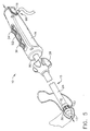
- FIGURE 1 is a perspective view of an anastomotic ring applier device, shown with a retracted tip.
- FIGURE 2 is a partial perspective view of the distal portion of an anastomotic ring applier device holding an anastomotic ring in an unactuated position.
- FIGURE 3 is a partial perspective view of the distal portion of the device of FIGURE 2 holding an anastomotic ring in the actuated position.
- FIGURE 4 is a frontal view of an actuated anastomotic ring.
- FIGURE 5 is a perspective view of the device of FIGURE 1, shown with the tip extended.
- FIGURE 6 is a perspective view of the device of FIGURE 1, shown with the sheath retracted.
- FIGURE 7 is a perspective view of the device of FIGURE 1, shown with a distal portion of the ring deployment mechanism actuated.
- FIGURE 8 is a perspective view of the device of FIGURE 1, shown with both a distal portion and a proximal portion of the ring deployment mechanism partially actuated.
- FIGURE 9 is a perspective view of the device of FIGURE 1, shown with both a distal portion and a proximal portion of the ring deployment mechanism fully actuated.
- FIGURE 10 is a perspective view of the device of FIGURE 1, shown with balloons inflated.
- FIGURE 11 is a partial exploded view of the distal portion of the device of FIGURE 1.
- FIGURE 12 is an exploded view of an actuation mechanism of the device of FIGURE 1.
- FIGURE 13 is a partial cross-sectional view of distal and proximal portions of the device of FIGURE 1, shown with a retracted tip.
- FIGURE 14 is a partial cross-sectional view of distal and proximal portions of the device of FIGURE 1, shown with the tip extended.
- FIGURE 15 is a partial cross-sectional view of distal and proximal portions of the device of FIGURE 1, shown with the sheath retracted.
- FIGURE 16 is a partial cross-sectional view of distal and proximal portions of the device of FIGURE 1, shown with a distal portion of the ring deployment mechanism actuated.
- FIGURE 17 is a partial cross-sectional view of distal and proximal portions of the device of FIGURE 1, shown with both a distal portion and a proximal portion of the ring deployment mechanism partially actuated.
- FIGURE 18 is a partial cross-sectional view of distal and proximal portions of the device of FIGURE 1, shown inserted through an anastomotic opening with both a proximal and a distal portion of a ring deployment mechanism fully actuated.
- FIGURE 19 is a partial cross-sectional view of distal and proximal portions of the device of FIGURE 1, shown with balloons inflated.
- FIGURE 20 is a cross-sectional view taken at
Plane 20 of the device of FIGURE 13. - FIGURE 21 is a cross-sectional view taken at
Plane 21 of the device of FIGURE 13. - Turning to the Drawings, wherein like numerals denote like components throughout the several views, FIG. 1 depicts an applier 10 that is operable to deploy and actuate an anastomotic ring device (not pictured in FIG. 1) from a generally cylindrical shape to one having properties of a hollow rivet, or ring, capable of forming an anastomotic attachment at an anastomosis target site, such as in a bariatric gastric bypass of a morbidly obese patient. FIG. 2 depicts another
applier 12. It will be appreciated that appliers 10, 12 may be used in a variety of ways, including but not limited to laparoscopically or endoscopically. Applier 12 is shown in FIG. 2 with ananastomotic ring 14 on adeployment mechanism 16. In FIG. 2,anastomotic ring 14 is shown in the compressed, cylindrically-shaped position. In FIG. 3,deployment mechanism 16 ofapplier 12 has movedanastomotic ring 14 to the actuated, hollow rivet-shaped position. FIG. 4 is a close-up view ofanastomotic ring 14 in the actuated position.Anastomotic ring 14 may comprise a shape memory effect (SME) material, such as nitinol by way of example only, that further assists in actuation to an engaging hollow rivet shape. Other suitableanastomotic ring 14 materials will be apparent to those of ordinary skill in the art. An exemplaryanastomotic ring 14 is described in detail in U.S. Patent Application Publ. No.US 2003/0032967 to Park et al. - It will be appreciated that the terms "proximal" and "distal" are used herein with reference to a clinician gripping a handle of
applier 10. It will be further appreciated that for convenience and clarity, spatial terms such as "right", "left", "vertical" and "horizontal" are used herein with respect to the drawings. However, surgical instruments are used in many orientations and positions, and these terms are not intended to be limiting and absolute. In addition, aspects of the invention have application to surgical procedures performed endoscopically and laparoscopically, as well as an open procedure or other procedures. Use herein of one of these or similar terms should not be construed to limit the present invention for use in only one category of surgical procedure. - Referring to FIGS. 1 and 5-9,
applier 10 of the present example is operable to deploy an anastomotic ring. As shown,applier 10 of the present example comprises atip 13, ashaft 15, and ahandle 19.Shaft 15 comprises atubular sheath 24.Tubular sheath 24 is moveable from a first position to a second position.Shaft 15 further comprises aring deployment mechanism 26 located at its distal end, proximal oftip 13. In the first position,sheath 24 is configured to cover ring deployment mechanism 26 (FIGS. 1 and 13) to prevent tissue from catching ondeployment mechanism 26 during insertion and extraction ofapplier 10.Sheath 24 is configured such thatdeployment mechanism 26 is exposed and free to actuate whensheath 24 is in the second position (FIGS. 6-10 and 15-19).Applier 10 further comprises asheath actuator 28 operable to movesheath 24 between the first and second positions. Suitable alternatives tosheath 24 and/orsheath actuator 28 will be apparent to those of ordinary skill in the art.Applier 10 of the present example also includes atip actuator 18 located onhandle 19.Tip actuator 18 is operable to movetip 13 from a retracted position (shown in FIGS. 1 and 13) to an extended position (shown in FIGS. 5-10 and 14-19). Such movement is effected through communication of motion bytip tube 90, which is fixedly secured to tip 13 andtip actuator 18.Tip tube 90 is located withinshaft 15, and is coaxially aligned withsheath 24. - A
distal balloon 30 is circumferentially disposed about a proximal portion oftip 13. Aproximal balloon 30 is circumferentially disposed about a distal portion ofsheath 24. Uses for and other features of distal andproximal balloons - Referring now to FIGS. 6-11 and 13-19,
ring deployment mechanism 26 of the present example comprises a set ofproximal fingers 60 and a set ofdistal fingers 62. Handle 19 ofapplier 10 further comprises a pair ofdeployment actuators first deployment actuator 34 is operable to actuateproximal fingers 60 ofring deployment mechanism 26; andsecond deployment actuator 36 is operable to actuatedistal fingers 62 ofring deployment mechanism 26. In FIGS. 7 and 13,distal fingers 62 are shown in the actuated position for deploying a distal portion of ananastomotic ring 14.Arrow 42 depicts actuating motion ofsecond actuator 36. In FIGS. 8 and 14,proximal fingers 60 are shown in the actuated position for deploying a proximal portion ofanastomotic ring 14 to complete an anastomotic attachment between proximate tissue walls.Arrow 50 depicts the actuating motion offirst actuator 34. - Both
proximal fingers 60 anddistal fingers 62 are in a double-hinged relationship with astationary mid-ring 64 ofring deployment mechanism 26.Proximal fingers 60 are configured to slide towardmid-ring 64 in response to actuation offirst actuator 34, which causesproximal fingers 60 to actuate outwardly relative toshaft 15.Mid-ring 64 is held stationary by astationary ground tube 65. Similarly,distal fingers 62 are configured to slide towardmid-ring 64 in response to actuation ofsecond actuator 36, which causesdistal fingers 62 to actuate outwardly relative toshaft 15.Fingers anastomotic ring 14 by engaging petals 51 prior to and during deployment of theanastomotic ring 14, and release petals 51 upon deployment of theanastomotic ring 14. - As shown in FIGS. 11 and 13-20, the above-described actuating components of
ring deployment mechanism 26 comprise a series ofconcentric tubes shaft 15. As will be discussed in greater detail below, aninner tube 82 is configured to transmit actuating force todistal fingers 62, while anouter tuber 80 is configured to transmit actuating force toproximal fingers 60. While, in the present example,tip tube 90 is not configured to transmit actuating force to ringdeployment mechanism 26,tip tube 90 is coaxially aligned withconcentric tubes inner tube 82. Abushing 66 is included withinshaft 15 to keep theconcentric tubes tip tube 90 centered. It will be appreciated, however, that the above-described components need not be concentrically or coaxially aligned, and that any suitable alternative tobushing 66 may be used. Similarly, any suitable alternative totubes - It will also be appreciated that any suitable alternative(s) to
ring deployment mechanism 26 and/ordeployment actuators - To prevent inadvertent deployment of
ring deployment mechanism 26,applier 10 of the present example is provided with a lockingelement 52. In the present example, lockingelement 52 is operable to move from a locked position to an unlocked position. In FIGS. 1, 5-6, 10, 13-15, and 19, lockingelement 52 is shown in a locked position preventing actuating movement offirst actuator 34 andsecond actuator 36. In FIGS. 7-9 and 17-18, lockingelement 52 is shown in the unlocked position, allowingactuators - As stated above,
first deployment actuator 34 of the present example is operable to controlproximal fingers 60 andsecond deployment actuator 36 is operable to controldistal fingers 62. Referring now to FIGS. 12-21, first and secondring deployment actuators grooves 67 that are configured to slide on atrack 68 ofhandle 19. As mentioned above, lockingelement 52 may be utilized to prevent inadvertent movement of first orsecond actuators first actuator 34 is fixedly attached to aproximal portion 74 oftrack 68.Track 68 is slideable withinhandle 19. Adistal portion 76 oftrack 68 is fixedly attached to aslider 78, which is fixedly secured toouter tube 80. Longitudinal motion offirst actuator 34 is thereby operable to cause corresponding longitudinal motion oftrack 68,slider 78, andouter tube 80. Other suitable relationships between these components, as well as alternative components, will be apparent to those of ordinary skill in the art. - The proximal end of
ground tube 65 is fixedly attached to anchormember 84.Anchor member 84 is configured to engage withbosses 86, which are integral withhandle 19. Accordingly, in the present example,anchor member 84 andbosses 86 are configured to prevent relative movement betweenground tube 65 and handle 19. Thus,ground tube 65 prevents relative longitudinal movement betweenmid-ring 64 ofring deployment mechanism 26 and handle 19. Of course, any other configuration may be used. -
Second actuator 36 is connected toinner tube 82.Inner tube 82 extends longitudinally throughground tube 65.Inner tube 82 is operable to communicate motion todistal fingers 62. In this manner,first actuator 34 controls actuation ofproximal fingers 60, andsecond actuator 36 controls actuation ofdistal fingers 62. - It should be noted that although
second actuator 36 is configured to slide ontrack 68 in the present example,second actuator 36 is not statically attached to track 68. Therefore, longitudinal movement oftrack 68 caused by motion offirst actuator 34 does not cause longitudinal movement ofsecond actuator 36. Of course, handle 19 and components thereof may be configured in any other suitable way. By way of example only,first actuator 34 may be configured to control actuation ofdistal fingers 62, andsecond actuator 36 may be configured to control actuation ofproximal fingers 60. Still other suitable alternative configurations will be apparent to those of ordinary skill in the art. - As shown, handle 19 further comprises a
balloon port 92, which is located intip actuator 18,Balloon port 92 is configured to receive a pressurized medium, such as air, liquid, or the like, from an external source.Balloon port 92 is in fluid communication withsplitter 94, which is further in fluid communication with twoballoon conduits 96. Each of theballoon conduits 96 is in fluid communication with arespective balloon balloon port 92, and may be further communicated to eachballoon splitter 94 andballoon conduits 96. One of the balloon conduits 96 (the one that is in communication with distal balloon 30) is located insidetip tube 90, while theother balloon conduit 96 is located withinsheath 24, outside ofouter tube 80. Of course, any other positioning forballoon conduits 96 may be used. - In response to receiving a pressurized medium, each
balloon balloons balloons balloons balloons - While the
applier 10 of the present example employssplitter 94 to direct a pressurized medium to eachballoon balloon balloon - In addition, handle 19 further comprises an
insufflation port 98, which is positioned at the bottom ofhandle 19 at the proximal end ofhandle 19.Insufflation port 98 is configured to receive a pressurized medium, such as air, liquid, or the like, from an external source.Insufflation tube 100 is in fluid communication withinsufflation port 98. The distal end ofinsufflation tube 100 is located insidesheath 24, outsideouter tube 80, and opens intosheath 24. Accordingly, and as shown in FIG. 19, a pressurized medium such as air may be introduced to the anastomosis site for insufflation or other purposes by communicating such pressurized medium through theinsufflation port 98 andinsufflation tube 100, whereby the pressurized medium will enter the anastomosis site via the open end ofsheath 24. Alternatively,insufflation tube 100 may open at any suitable location, and/or the anastomosis site may be insufflated by any other suitable means, device, or method. In any event, such insufflation may be useful for leak and/or pressure testing the anastomosis whileballoons - While, in the present example, a pressurized medium is communicated to
ports applier 10 may have a pressurized vessel containing a pressurized medium housed within or proximately attached toapplier 10. Such a vessel may provide a pressurized fluid medium to eitherport ports - In use,
applier 10 may be inserted adjacent an anastomotic opening in proximate tissue walls.Tip 13 may initially be located in the retracted position, as depicted in FIGS. 1 and 13, during insertion. Oncetip 13 has been inserted through the anastomotic opening,tip 13 may be extended usingtip actuator 18, as depicted in FIGS. 5 and 14.Sheath actuator 28 may be used to retractsheath 24 to exposering deployment mechanism 26, as shown in FIGS. 6 and 15. Withring deployment mechanism 26 exposed, and with lockingelement 52 depressed,second actuator 36 may be actuated, thereby causing actuation ofdistal fingers 62, as shown in FIGS. 7 and 16. Next,first actuator 34 may be actuated, thereby causing actuation ofproximal fingers 60, as shown in FIGS. 8 and 17. First andsecond actuators applier 10 may be repositioned, such as by movingapplier 10 proximally, before inflation and/or insufflation. Other suitable positions forapplier 10 during inflation and/or insufflation will be apparent to those of ordinary skill in the art. Upon completion of testing, balloons 30, 32 may be deflated, andfingers applier 10 may be removed. Still other uses forapplier 10 will be apparent to those of ordinary skill in the art.. - Having shown and described various embodiments and concepts of the invention, further adaptations of the methods and systems described herein can be accomplished by appropriate modifications by one of ordinary skill in the art without departing from the scope of the invention. Several of such potential alternatives, modifications, and variations have been mentioned, and others will be apparent to those skilled in the art in light of the foregoing teachings. Accordingly, the invention is intended to embrace all such alternatives, modifications and variations as may fall within the spirit and scope of the appended claims and is understood not to be limited to the details of structure and operation shown and described in the specification and drawings. Additional advantages may readily appear to those skilled in the art.
Claims (12)
- A surgical instrument operable to test an anastomosis, wherein the anastomosis is located at an anastomosis site in a patient, the instrument comprising:(a) a handle; and(b) a shaft connected to the handle, the shaft comprising:(i) an outer surface,(ii) a proximal end, wherein the handle is located at the proximal end of the shaft,(iii) a distal end, wherein the distal end of the shaft comprises two or more inflatable members adjacent the outer surface, wherein the two or more inflatable members are spaced to permit at least one inflatable member of the two or more inflatable members to be positioned on a first side of the anastomosis and another at least one inflatable member of the two or more inflatable members to be positioned on a second side of the anastomosis, and(iv) one or more conduits configured to communicate a pressurized medium to at least one of the two or more inflatable members.
- The instrument of claim 1, further comprising an insufflation member, wherein the insufflation member is configured to communicate a pressurized medium to the anastomosis site.
- The instrument of claim 2, wherein the insufflation member comprises an insufflation tube, wherein the insufflation tube is positioned along the shaft.
- The instrument of claim 2, wherein the handle comprises an insufflation port, wherein the insufflation port is in fluid communication with the insufflation member, wherein the insufflation port is configured to receive a pressurized medium.
- The instrument of claim 1, wherein the handle comprises an inflation port, wherein the inflation port is in fluid communication with at least one of the one or more conduits, wherein the inflation port is configured to receive a pressurized medium.
- The instrument of claim 1, wherein the two or more inflatable members comprise a pair of circumferential balloons.
- The instrument of claim 1, further comprising a ring deployment mechanism located at the distal end of the shaft adjacent the two or more inflatable members, wherein the ring deployment mechanism is operable to deploy an anastomotic ring at the anastomosis site.
- The instrument of claim 7, wherein the ring deployment mechanism is positioned between a pair of inflatable members of the two or more inflatable members.
- The instrument of claim 7, wherein the ring deployment mechanism comprises a plurality of fingers operable to actuate outwardly relative to the shaft to deploy the anastomotic ring.
- The instrument of claim 9, wherein the plurality of fingers comprises a plurality of distal fingers and a plurality of proximal fingers.
- A surgical instrument operable to test an anastomosis, wherein the anastomosis is located at an anastomosis site in a patient, wherein the anastomosis site comprises two or more lumens, the instrument comprising:(a) an elongate shaft;(b) a ring deployment mechanism in communication with the shaft, wherein the ring deployment mechanism is operable to deploy an anastomotic ring device at the anastomosis site; and(c) at least one inflatable member in communication with the shaft, wherein the at least one inflatable member is configured to provide a seal of at least one of the one or more lumens, wherein the seal is adjacent the anastomosis, wherein the seal is provided upon inflation of the at least one inflatable member.
- A method for testing an anastomosis, wherein the anastomosis is located at an anastomosis site in a patient, wherein the anastomosis site comprises a pair of adjacent lumens, the method comprising:(a) providing an instrument at the anastomosis site, wherein the instrument comprises:(i) an elongate shaft,(ii) two inflatable members in communication with the shaft, wherein the two inflatable members are spaced to permit one of the inflatable members to be positioned in one of the lumens of the anastomosis site and the other of the inflatable members to be positioned in the other lumen of the anastomosis site,(iii) one or more conduits configured to communicate a pressurized fluid to the inflatable members, and(iv) an insufflation member, wherein the insufflation member is configured to communicate a pressurized fluid to the anastomosis site;(b) inflating the inflatable members, wherein the act of inflating the inflatable members comprises communicating a pressurized fluid to the inflatable members via the one or more conduits, wherein, upon inflation of the inflatable members, each lumen of the anastomosis site is sealed;(c) insufflating the anastomosis site, wherein the act of insufflating the anastomosis site comprises communicating a pressurized fluid to the anastomosis site via the insufflation member, wherein the act of insufflating is performed upon the lumens of the anastomosis site being sealed by the inflatable members;(d) releasing pressurized fluid from the inflatable members; and(e) removing the instrument from the patient.
Applications Claiming Priority (1)
| Application Number | Priority Date | Filing Date | Title |
|---|---|---|---|
| US11/122,761 US7645288B2 (en) | 2005-05-05 | 2005-05-05 | Anastomotic ring applier with inflatable members |
Publications (2)
| Publication Number | Publication Date |
|---|---|
| EP1719460A1 true EP1719460A1 (en) | 2006-11-08 |
| EP1719460B1 EP1719460B1 (en) | 2008-07-09 |
Family
ID=36939211
Family Applications (1)
| Application Number | Title | Priority Date | Filing Date |
|---|---|---|---|
| EP06252383A Active EP1719460B1 (en) | 2005-05-05 | 2006-05-04 | Anastomotic ring applier with inflatable members |
Country Status (16)
| Country | Link |
|---|---|
| US (1) | US7645288B2 (en) |
| EP (1) | EP1719460B1 (en) |
| JP (1) | JP5160047B2 (en) |
| KR (1) | KR101347067B1 (en) |
| CN (1) | CN1861005B (en) |
| AT (1) | ATE400223T1 (en) |
| AU (1) | AU2006201809B2 (en) |
| BR (1) | BRPI0601613B8 (en) |
| CA (1) | CA2545688C (en) |
| DE (1) | DE602006001679D1 (en) |
| HK (1) | HK1096835A1 (en) |
| IL (1) | IL175382A0 (en) |
| MX (1) | MXPA06005165A (en) |
| RU (1) | RU2428133C2 (en) |
| SG (1) | SG126927A1 (en) |
| TW (1) | TWI389666B (en) |
Cited By (1)
| Publication number | Priority date | Publication date | Assignee | Title |
|---|---|---|---|---|
| CN104027151A (en) * | 2014-06-06 | 2014-09-10 | 山东威瑞外科医用制品有限公司 | Damping stapler |
Families Citing this family (63)
| Publication number | Priority date | Publication date | Assignee | Title |
|---|---|---|---|---|
| US20070021759A1 (en) * | 2005-07-22 | 2007-01-25 | Ethicon Endo-Surgery, Inc. | Flexible endoscopic anastomotic ring applier device |
| US7591828B2 (en) * | 2005-07-22 | 2009-09-22 | Ethicon Endo-Surgery, Inc. | Resposable anastomotic ring applier device |
| US7655004B2 (en) | 2007-02-15 | 2010-02-02 | Ethicon Endo-Surgery, Inc. | Electroporation ablation apparatus, system, and method |
| US7815662B2 (en) | 2007-03-08 | 2010-10-19 | Ethicon Endo-Surgery, Inc. | Surgical suture anchors and deployment device |
| US8075572B2 (en) | 2007-04-26 | 2011-12-13 | Ethicon Endo-Surgery, Inc. | Surgical suturing apparatus |
| US8100922B2 (en) | 2007-04-27 | 2012-01-24 | Ethicon Endo-Surgery, Inc. | Curved needle suturing tool |
| US8262655B2 (en) | 2007-11-21 | 2012-09-11 | Ethicon Endo-Surgery, Inc. | Bipolar forceps |
| US8568410B2 (en) | 2007-08-31 | 2013-10-29 | Ethicon Endo-Surgery, Inc. | Electrical ablation surgical instruments |
| US8579897B2 (en) | 2007-11-21 | 2013-11-12 | Ethicon Endo-Surgery, Inc. | Bipolar forceps |
| US8216159B1 (en) | 2007-10-08 | 2012-07-10 | Tools For Surgery, Llc | Anastomosis leak testing apparatus and methods |
| US8480657B2 (en) | 2007-10-31 | 2013-07-09 | Ethicon Endo-Surgery, Inc. | Detachable distal overtube section and methods for forming a sealable opening in the wall of an organ |
| US20090112059A1 (en) | 2007-10-31 | 2009-04-30 | Nobis Rudolph H | Apparatus and methods for closing a gastrotomy |
| JP2009153764A (en) * | 2007-12-27 | 2009-07-16 | Nippon Sherwood Medical Industries Ltd | Insertion assisting tool for endoscope |
| US8262680B2 (en) | 2008-03-10 | 2012-09-11 | Ethicon Endo-Surgery, Inc. | Anastomotic device |
| US8317806B2 (en) | 2008-05-30 | 2012-11-27 | Ethicon Endo-Surgery, Inc. | Endoscopic suturing tension controlling and indication devices |
| US8771260B2 (en) | 2008-05-30 | 2014-07-08 | Ethicon Endo-Surgery, Inc. | Actuating and articulating surgical device |
| US8114072B2 (en) | 2008-05-30 | 2012-02-14 | Ethicon Endo-Surgery, Inc. | Electrical ablation device |
| US8070759B2 (en) | 2008-05-30 | 2011-12-06 | Ethicon Endo-Surgery, Inc. | Surgical fastening device |
| US8652150B2 (en) | 2008-05-30 | 2014-02-18 | Ethicon Endo-Surgery, Inc. | Multifunction surgical device |
| US8679003B2 (en) | 2008-05-30 | 2014-03-25 | Ethicon Endo-Surgery, Inc. | Surgical device and endoscope including same |
| US8906035B2 (en) | 2008-06-04 | 2014-12-09 | Ethicon Endo-Surgery, Inc. | Endoscopic drop off bag |
| US8403926B2 (en) | 2008-06-05 | 2013-03-26 | Ethicon Endo-Surgery, Inc. | Manually articulating devices |
| US8361112B2 (en) | 2008-06-27 | 2013-01-29 | Ethicon Endo-Surgery, Inc. | Surgical suture arrangement |
| US8262563B2 (en) | 2008-07-14 | 2012-09-11 | Ethicon Endo-Surgery, Inc. | Endoscopic translumenal articulatable steerable overtube |
| US8888792B2 (en) | 2008-07-14 | 2014-11-18 | Ethicon Endo-Surgery, Inc. | Tissue apposition clip application devices and methods |
| US8211125B2 (en) | 2008-08-15 | 2012-07-03 | Ethicon Endo-Surgery, Inc. | Sterile appliance delivery device for endoscopic procedures |
| US8529563B2 (en) | 2008-08-25 | 2013-09-10 | Ethicon Endo-Surgery, Inc. | Electrical ablation devices |
| US8241204B2 (en) | 2008-08-29 | 2012-08-14 | Ethicon Endo-Surgery, Inc. | Articulating end cap |
| US8480689B2 (en) | 2008-09-02 | 2013-07-09 | Ethicon Endo-Surgery, Inc. | Suturing device |
| US8409200B2 (en) | 2008-09-03 | 2013-04-02 | Ethicon Endo-Surgery, Inc. | Surgical grasping device |
| US8114119B2 (en) | 2008-09-09 | 2012-02-14 | Ethicon Endo-Surgery, Inc. | Surgical grasping device |
| US8337394B2 (en) | 2008-10-01 | 2012-12-25 | Ethicon Endo-Surgery, Inc. | Overtube with expandable tip |
| US8157834B2 (en) | 2008-11-25 | 2012-04-17 | Ethicon Endo-Surgery, Inc. | Rotational coupling device for surgical instrument with flexible actuators |
| US8172772B2 (en) | 2008-12-11 | 2012-05-08 | Ethicon Endo-Surgery, Inc. | Specimen retrieval device |
| US8361066B2 (en) | 2009-01-12 | 2013-01-29 | Ethicon Endo-Surgery, Inc. | Electrical ablation devices |
| US8828031B2 (en) | 2009-01-12 | 2014-09-09 | Ethicon Endo-Surgery, Inc. | Apparatus for forming an anastomosis |
| US9226772B2 (en) | 2009-01-30 | 2016-01-05 | Ethicon Endo-Surgery, Inc. | Surgical device |
| US8252057B2 (en) | 2009-01-30 | 2012-08-28 | Ethicon Endo-Surgery, Inc. | Surgical access device |
| US8037591B2 (en) | 2009-02-02 | 2011-10-18 | Ethicon Endo-Surgery, Inc. | Surgical scissors |
| US20100249700A1 (en) * | 2009-03-27 | 2010-09-30 | Ethicon Endo-Surgery, Inc. | Surgical instruments for in vivo assembly |
| US20110098704A1 (en) | 2009-10-28 | 2011-04-28 | Ethicon Endo-Surgery, Inc. | Electrical ablation devices |
| US8608652B2 (en) | 2009-11-05 | 2013-12-17 | Ethicon Endo-Surgery, Inc. | Vaginal entry surgical devices, kit, system, and method |
| US8353487B2 (en) | 2009-12-17 | 2013-01-15 | Ethicon Endo-Surgery, Inc. | User interface support devices for endoscopic surgical instruments |
| US8496574B2 (en) | 2009-12-17 | 2013-07-30 | Ethicon Endo-Surgery, Inc. | Selectively positionable camera for surgical guide tube assembly |
| US8506564B2 (en) | 2009-12-18 | 2013-08-13 | Ethicon Endo-Surgery, Inc. | Surgical instrument comprising an electrode |
| US9028483B2 (en) | 2009-12-18 | 2015-05-12 | Ethicon Endo-Surgery, Inc. | Surgical instrument comprising an electrode |
| US9005198B2 (en) | 2010-01-29 | 2015-04-14 | Ethicon Endo-Surgery, Inc. | Surgical instrument comprising an electrode |
| US10092291B2 (en) | 2011-01-25 | 2018-10-09 | Ethicon Endo-Surgery, Inc. | Surgical instrument with selectively rigidizable features |
| US9254169B2 (en) | 2011-02-28 | 2016-02-09 | Ethicon Endo-Surgery, Inc. | Electrical ablation devices and methods |
| US9314620B2 (en) | 2011-02-28 | 2016-04-19 | Ethicon Endo-Surgery, Inc. | Electrical ablation devices and methods |
| US9233241B2 (en) | 2011-02-28 | 2016-01-12 | Ethicon Endo-Surgery, Inc. | Electrical ablation devices and methods |
| WO2012125785A1 (en) | 2011-03-17 | 2012-09-20 | Ethicon Endo-Surgery, Inc. | Hand held surgical device for manipulating an internal magnet assembly within a patient |
| US8986199B2 (en) | 2012-02-17 | 2015-03-24 | Ethicon Endo-Surgery, Inc. | Apparatus and methods for cleaning the lens of an endoscope |
| US9427255B2 (en) | 2012-05-14 | 2016-08-30 | Ethicon Endo-Surgery, Inc. | Apparatus for introducing a steerable camera assembly into a patient |
| US9078662B2 (en) | 2012-07-03 | 2015-07-14 | Ethicon Endo-Surgery, Inc. | Endoscopic cap electrode and method for using the same |
| US9545290B2 (en) | 2012-07-30 | 2017-01-17 | Ethicon Endo-Surgery, Inc. | Needle probe guide |
| US9572623B2 (en) | 2012-08-02 | 2017-02-21 | Ethicon Endo-Surgery, Inc. | Reusable electrode and disposable sheath |
| US10314649B2 (en) | 2012-08-02 | 2019-06-11 | Ethicon Endo-Surgery, Inc. | Flexible expandable electrode and method of intraluminal delivery of pulsed power |
| US9277957B2 (en) | 2012-08-15 | 2016-03-08 | Ethicon Endo-Surgery, Inc. | Electrosurgical devices and methods |
| US10098527B2 (en) | 2013-02-27 | 2018-10-16 | Ethidcon Endo-Surgery, Inc. | System for performing a minimally invasive surgical procedure |
| US20170007276A1 (en) * | 2015-07-07 | 2017-01-12 | Empire Technology Development Llc | Gallstone removal through cholecystoduodenal fistula by anastomosis device |
| US10130368B2 (en) | 2016-04-01 | 2018-11-20 | Ethicon, Inc. | Expandable compression rings for improved anastomotic joining of tissues |
| US10595871B2 (en) * | 2016-05-10 | 2020-03-24 | Covidien Lp | Insertion instrument, adapter assemblies and protector assemblies for a flexible circular stapler |
Citations (4)
| Publication number | Priority date | Publication date | Assignee | Title |
|---|---|---|---|---|
| US20020183769A1 (en) * | 2001-05-30 | 2002-12-05 | St. Jude Medical Atg, Inc. | Medical grafting methods and apparatus |
| EP1340462A1 (en) * | 2002-02-28 | 2003-09-03 | Ethicon, Inc. | Sponge for creating an anastomosis between vessels |
| US20030229364A1 (en) * | 2002-06-11 | 2003-12-11 | Michael Seiba | Device for anastomosis in a radical retropubic prostatectomy |
| EP1520531A1 (en) * | 2003-09-30 | 2005-04-06 | Ethicon Endo-Surgery | Anastomosis applier |
Family Cites Families (22)
| Publication number | Priority date | Publication date | Assignee | Title |
|---|---|---|---|---|
| US4611602A (en) | 1984-07-19 | 1986-09-16 | Bionexus, Inc. | Instrument and method of tubal insufflation |
| US4971034A (en) | 1985-01-16 | 1990-11-20 | Asahi Kogaku Kogyo Kabushiki Kaisha | Body cavity pressure adjusting device for endoscope and laser medical treatment apparatus including body cavity pressure adjusting device |
| US5053016A (en) | 1987-12-31 | 1991-10-01 | United States Surgical Corporation | Valve seat for an insufflation cannula assembly |
| US4943280A (en) | 1987-12-31 | 1990-07-24 | United States Surgical Corporaiton | Self-seating flapper valve for an insufflation cannula assembly |
| US5127909A (en) | 1990-04-05 | 1992-07-07 | United States Surgical Corporation | Flapper valve for an insufflation cannula assembly |
| US5226876A (en) | 1990-10-11 | 1993-07-13 | Wilson Cook Medical, Inc. | Operating channel/insufflation port assemblies |
| US5425738A (en) * | 1992-04-08 | 1995-06-20 | American Cyanamid Company | Endoscopic anastomosis ring insertion device and method of use thereof |
| US5345949A (en) * | 1992-09-02 | 1994-09-13 | Shlain Leonard M | Methods for use in surgical gastroplastic procedure |
| US5904697A (en) | 1995-02-24 | 1999-05-18 | Heartport, Inc. | Devices and methods for performing a vascular anastomosis |
| US5855312A (en) | 1996-07-25 | 1999-01-05 | Toledano; Haviv | Flexible annular stapler for closed surgery of hollow organs |
| AU748152C (en) * | 1997-09-26 | 2004-03-25 | Cryolife, Inc. | Sutureless anastomotic technique using a bioadhesive and device therefor |
| NL1007349C2 (en) * | 1997-10-24 | 1999-04-27 | Suyker Wilhelmus Joseph Leonardus | System for the mechanical production of anastomoses between hollow structures; as well as device and applicator for use therewith. |
| CN2335574Y (en) * | 1998-02-15 | 1999-09-01 | 王本龙 | Air bag type esophagogastrostomy supporter |
| US6398802B1 (en) * | 1999-06-21 | 2002-06-04 | Scimed Life Systems, Inc. | Low profile delivery system for stent and graft deployment |
| US6451029B1 (en) * | 1999-08-23 | 2002-09-17 | University Of South Florida | Intestinal stapling device and method |
| KR100891045B1 (en) | 2001-06-20 | 2009-03-31 | 파크 메디칼 엘엘씨 | Anastomotic device |
| US8551126B2 (en) * | 2002-08-22 | 2013-10-08 | Ams Research Corporation | Anastomosis device and related methods |
| GB0307826D0 (en) * | 2003-04-04 | 2003-05-07 | Univ London | A device for transfixing and joining tissue |
| US20050059992A1 (en) | 2003-09-17 | 2005-03-17 | Leiboff Arnold R. | Air introduction device for anastomotic leak testing |
| US20050070939A1 (en) * | 2003-09-30 | 2005-03-31 | Jean Beaupre | Unfolding anastomosis ring device |
| US7608086B2 (en) * | 2003-09-30 | 2009-10-27 | Ethicon Endo-Surgery, Inc. | Anastomosis wire ring device |
| EP1773209A4 (en) * | 2004-06-23 | 2009-09-02 | Ethicon Endo Surgery Inc | Instrument for effecting anastomosis of respective tissues defining two body lumens |
-
2005
- 2005-05-05 US US11/122,761 patent/US7645288B2/en active Active
-
2006
- 2006-05-01 AU AU2006201809A patent/AU2006201809B2/en not_active Ceased
- 2006-05-02 JP JP2006128538A patent/JP5160047B2/en not_active Expired - Fee Related
- 2006-05-02 IL IL175382A patent/IL175382A0/en unknown
- 2006-05-03 CA CA2545688A patent/CA2545688C/en not_active Expired - Fee Related
- 2006-05-04 SG SG200603002A patent/SG126927A1/en unknown
- 2006-05-04 KR KR1020060040484A patent/KR101347067B1/en active IP Right Grant
- 2006-05-04 RU RU2006115422/14A patent/RU2428133C2/en not_active IP Right Cessation
- 2006-05-04 TW TW095115824A patent/TWI389666B/en not_active IP Right Cessation
- 2006-05-04 DE DE602006001679T patent/DE602006001679D1/en active Active
- 2006-05-04 AT AT06252383T patent/ATE400223T1/en not_active IP Right Cessation
- 2006-05-04 EP EP06252383A patent/EP1719460B1/en active Active
- 2006-05-05 BR BRPI0601613A patent/BRPI0601613B8/en not_active IP Right Cessation
- 2006-05-08 MX MXPA06005165A patent/MXPA06005165A/en active IP Right Grant
- 2006-05-08 CN CN2006100774722A patent/CN1861005B/en active Active
-
2007
- 2007-04-12 HK HK07103844A patent/HK1096835A1/en not_active IP Right Cessation
Patent Citations (4)
| Publication number | Priority date | Publication date | Assignee | Title |
|---|---|---|---|---|
| US20020183769A1 (en) * | 2001-05-30 | 2002-12-05 | St. Jude Medical Atg, Inc. | Medical grafting methods and apparatus |
| EP1340462A1 (en) * | 2002-02-28 | 2003-09-03 | Ethicon, Inc. | Sponge for creating an anastomosis between vessels |
| US20030229364A1 (en) * | 2002-06-11 | 2003-12-11 | Michael Seiba | Device for anastomosis in a radical retropubic prostatectomy |
| EP1520531A1 (en) * | 2003-09-30 | 2005-04-06 | Ethicon Endo-Surgery | Anastomosis applier |
Cited By (1)
| Publication number | Priority date | Publication date | Assignee | Title |
|---|---|---|---|---|
| CN104027151A (en) * | 2014-06-06 | 2014-09-10 | 山东威瑞外科医用制品有限公司 | Damping stapler |
Also Published As
| Publication number | Publication date |
|---|---|
| JP5160047B2 (en) | 2013-03-13 |
| RU2006115422A (en) | 2007-11-27 |
| DE602006001679D1 (en) | 2008-08-21 |
| CA2545688A1 (en) | 2006-11-05 |
| BRPI0601613A (en) | 2007-09-04 |
| SG126927A1 (en) | 2006-11-29 |
| MXPA06005165A (en) | 2007-01-31 |
| IL175382A0 (en) | 2006-09-05 |
| BRPI0601613B8 (en) | 2021-06-22 |
| RU2428133C2 (en) | 2011-09-10 |
| CN1861005B (en) | 2011-06-15 |
| HK1096835A1 (en) | 2007-06-15 |
| ATE400223T1 (en) | 2008-07-15 |
| EP1719460B1 (en) | 2008-07-09 |
| US20060253039A1 (en) | 2006-11-09 |
| AU2006201809A1 (en) | 2006-11-23 |
| KR101347067B1 (en) | 2013-12-31 |
| AU2006201809B2 (en) | 2012-09-13 |
| CA2545688C (en) | 2014-10-14 |
| CN1861005A (en) | 2006-11-15 |
| BRPI0601613B1 (en) | 2018-03-20 |
| TWI389666B (en) | 2013-03-21 |
| TW200711621A (en) | 2007-04-01 |
| US7645288B2 (en) | 2010-01-12 |
| JP2006312055A (en) | 2006-11-16 |
| KR20060115655A (en) | 2006-11-09 |
Similar Documents
| Publication | Publication Date | Title |
|---|---|---|
| EP1719460B1 (en) | Anastomotic ring applier with inflatable members | |
| US10993722B2 (en) | Expandable compression rings for improved anastomotic joining of tissues | |
| US7648515B2 (en) | Method and apparatus for anastomosis including an expandable anchor | |
| US7141055B2 (en) | Resection and anastomosis devices and methods | |
| EP2473119B1 (en) | Surgical device and accessories | |
| ES2688651T3 (en) | Specimen Recovery Apparatus | |
| WO2019204695A1 (en) | Surgical staplers and related methods | |
| EP3445260B1 (en) | Specimen retrieval system for use in endoscopic surgery | |
| AU2011202352A1 (en) | Single lumen access deployable ring for intralumenal anastomosis | |
| WO2012007044A1 (en) | A device for translumenal diversion of bile | |
| US7632285B2 (en) | Sheath for enabling insertion and extraction of anastomotic ring applier | |
| EP1719457B1 (en) | Anastomotic ring applier device providing forward and retrograde visualisation | |
| MXPA06004947A (en) | Sheath for enabling insertion and extraction of anastomotic ring applier | |
| MXPA06008305A (en) | Anastomotic ring applier for use in colorectal applications |
Legal Events
| Date | Code | Title | Description |
|---|---|---|---|
| PUAI | Public reference made under article 153(3) epc to a published international application that has entered the european phase |
Free format text: ORIGINAL CODE: 0009012 |
|
| AK | Designated contracting states |
Kind code of ref document: A1 Designated state(s): AT BE BG CH CY CZ DE DK EE ES FI FR GB GR HU IE IS IT LI LT LU LV MC NL PL PT RO SE SI SK TR |
|
| AX | Request for extension of the european patent |
Extension state: AL BA HR MK YU |
|
| 17P | Request for examination filed |
Effective date: 20070412 |
|
| REG | Reference to a national code |
Ref country code: HK Ref legal event code: DE Ref document number: 1096835 Country of ref document: HK |
|
| 17Q | First examination report despatched |
Effective date: 20070524 |
|
| AKX | Designation fees paid |
Designated state(s): AT BE BG CH CY CZ DE DK EE ES FI FR GB GR HU IE IS IT LI LT LU LV MC NL PL PT RO SE SI SK TR |
|
| GRAP | Despatch of communication of intention to grant a patent |
Free format text: ORIGINAL CODE: EPIDOSNIGR1 |
|
| GRAS | Grant fee paid |
Free format text: ORIGINAL CODE: EPIDOSNIGR3 |
|
| GRAA | (expected) grant |
Free format text: ORIGINAL CODE: 0009210 |
|
| AK | Designated contracting states |
Kind code of ref document: B1 Designated state(s): AT BE BG CH CY CZ DE DK EE ES FI FR GB GR HU IE IS IT LI LT LU LV MC NL PL PT RO SE SI SK TR |
|
| REG | Reference to a national code |
Ref country code: GB Ref legal event code: FG4D |
|
| REG | Reference to a national code |
Ref country code: CH Ref legal event code: EP |
|
| REF | Corresponds to: |
Ref document number: 602006001679 Country of ref document: DE Date of ref document: 20080821 Kind code of ref document: P |
|
| REG | Reference to a national code |
Ref country code: IE Ref legal event code: FG4D |
|
| NLV1 | Nl: lapsed or annulled due to failure to fulfill the requirements of art. 29p and 29m of the patents act | ||
| REG | Reference to a national code |
Ref country code: HK Ref legal event code: GR Ref document number: 1096835 Country of ref document: HK |
|
| PG25 | Lapsed in a contracting state [announced via postgrant information from national office to epo] |
Ref country code: NL Free format text: LAPSE BECAUSE OF FAILURE TO SUBMIT A TRANSLATION OF THE DESCRIPTION OR TO PAY THE FEE WITHIN THE PRESCRIBED TIME-LIMIT Effective date: 20080709 Ref country code: LT Free format text: LAPSE BECAUSE OF FAILURE TO SUBMIT A TRANSLATION OF THE DESCRIPTION OR TO PAY THE FEE WITHIN THE PRESCRIBED TIME-LIMIT Effective date: 20080709 Ref country code: IS Free format text: LAPSE BECAUSE OF FAILURE TO SUBMIT A TRANSLATION OF THE DESCRIPTION OR TO PAY THE FEE WITHIN THE PRESCRIBED TIME-LIMIT Effective date: 20081109 |
|
| PG25 | Lapsed in a contracting state [announced via postgrant information from national office to epo] |
Ref country code: ES Free format text: LAPSE BECAUSE OF FAILURE TO SUBMIT A TRANSLATION OF THE DESCRIPTION OR TO PAY THE FEE WITHIN THE PRESCRIBED TIME-LIMIT Effective date: 20081020 Ref country code: PT Free format text: LAPSE BECAUSE OF FAILURE TO SUBMIT A TRANSLATION OF THE DESCRIPTION OR TO PAY THE FEE WITHIN THE PRESCRIBED TIME-LIMIT Effective date: 20081209 Ref country code: FI Free format text: LAPSE BECAUSE OF FAILURE TO SUBMIT A TRANSLATION OF THE DESCRIPTION OR TO PAY THE FEE WITHIN THE PRESCRIBED TIME-LIMIT Effective date: 20080709 Ref country code: AT Free format text: LAPSE BECAUSE OF FAILURE TO SUBMIT A TRANSLATION OF THE DESCRIPTION OR TO PAY THE FEE WITHIN THE PRESCRIBED TIME-LIMIT Effective date: 20080709 Ref country code: BG Free format text: LAPSE BECAUSE OF FAILURE TO SUBMIT A TRANSLATION OF THE DESCRIPTION OR TO PAY THE FEE WITHIN THE PRESCRIBED TIME-LIMIT Effective date: 20081009 Ref country code: LV Free format text: LAPSE BECAUSE OF FAILURE TO SUBMIT A TRANSLATION OF THE DESCRIPTION OR TO PAY THE FEE WITHIN THE PRESCRIBED TIME-LIMIT Effective date: 20080709 Ref country code: SI Free format text: LAPSE BECAUSE OF FAILURE TO SUBMIT A TRANSLATION OF THE DESCRIPTION OR TO PAY THE FEE WITHIN THE PRESCRIBED TIME-LIMIT Effective date: 20080709 |
|
| PG25 | Lapsed in a contracting state [announced via postgrant information from national office to epo] |
Ref country code: BE Free format text: LAPSE BECAUSE OF FAILURE TO SUBMIT A TRANSLATION OF THE DESCRIPTION OR TO PAY THE FEE WITHIN THE PRESCRIBED TIME-LIMIT Effective date: 20080709 |
|
| PG25 | Lapsed in a contracting state [announced via postgrant information from national office to epo] |
Ref country code: EE Free format text: LAPSE BECAUSE OF FAILURE TO SUBMIT A TRANSLATION OF THE DESCRIPTION OR TO PAY THE FEE WITHIN THE PRESCRIBED TIME-LIMIT Effective date: 20080709 Ref country code: DK Free format text: LAPSE BECAUSE OF FAILURE TO SUBMIT A TRANSLATION OF THE DESCRIPTION OR TO PAY THE FEE WITHIN THE PRESCRIBED TIME-LIMIT Effective date: 20080709 |
|
| PLBE | No opposition filed within time limit |
Free format text: ORIGINAL CODE: 0009261 |
|
| STAA | Information on the status of an ep patent application or granted ep patent |
Free format text: STATUS: NO OPPOSITION FILED WITHIN TIME LIMIT |
|
| PG25 | Lapsed in a contracting state [announced via postgrant information from national office to epo] |
Ref country code: SK Free format text: LAPSE BECAUSE OF FAILURE TO SUBMIT A TRANSLATION OF THE DESCRIPTION OR TO PAY THE FEE WITHIN THE PRESCRIBED TIME-LIMIT Effective date: 20080709 Ref country code: RO Free format text: LAPSE BECAUSE OF FAILURE TO SUBMIT A TRANSLATION OF THE DESCRIPTION OR TO PAY THE FEE WITHIN THE PRESCRIBED TIME-LIMIT Effective date: 20080709 Ref country code: CZ Free format text: LAPSE BECAUSE OF FAILURE TO SUBMIT A TRANSLATION OF THE DESCRIPTION OR TO PAY THE FEE WITHIN THE PRESCRIBED TIME-LIMIT Effective date: 20080709 |
|
| 26N | No opposition filed |
Effective date: 20090414 |
|
| PG25 | Lapsed in a contracting state [announced via postgrant information from national office to epo] |
Ref country code: MC Free format text: LAPSE BECAUSE OF NON-PAYMENT OF DUE FEES Effective date: 20090531 |
|
| PG25 | Lapsed in a contracting state [announced via postgrant information from national office to epo] |
Ref country code: SE Free format text: LAPSE BECAUSE OF FAILURE TO SUBMIT A TRANSLATION OF THE DESCRIPTION OR TO PAY THE FEE WITHIN THE PRESCRIBED TIME-LIMIT Effective date: 20081009 |
|
| REG | Reference to a national code |
Ref country code: IE Ref legal event code: MM4A |
|
| PG25 | Lapsed in a contracting state [announced via postgrant information from national office to epo] |
Ref country code: IE Free format text: LAPSE BECAUSE OF NON-PAYMENT OF DUE FEES Effective date: 20090504 |
|
| PG25 | Lapsed in a contracting state [announced via postgrant information from national office to epo] |
Ref country code: PL Free format text: LAPSE BECAUSE OF FAILURE TO SUBMIT A TRANSLATION OF THE DESCRIPTION OR TO PAY THE FEE WITHIN THE PRESCRIBED TIME-LIMIT Effective date: 20080709 |
|
| PG25 | Lapsed in a contracting state [announced via postgrant information from national office to epo] |
Ref country code: GR Free format text: LAPSE BECAUSE OF FAILURE TO SUBMIT A TRANSLATION OF THE DESCRIPTION OR TO PAY THE FEE WITHIN THE PRESCRIBED TIME-LIMIT Effective date: 20081010 |
|
| REG | Reference to a national code |
Ref country code: CH Ref legal event code: PL |
|
| PG25 | Lapsed in a contracting state [announced via postgrant information from national office to epo] |
Ref country code: CH Free format text: LAPSE BECAUSE OF NON-PAYMENT OF DUE FEES Effective date: 20100531 Ref country code: LI Free format text: LAPSE BECAUSE OF NON-PAYMENT OF DUE FEES Effective date: 20100531 |
|
| PG25 | Lapsed in a contracting state [announced via postgrant information from national office to epo] |
Ref country code: LU Free format text: LAPSE BECAUSE OF NON-PAYMENT OF DUE FEES Effective date: 20090504 |
|
| PG25 | Lapsed in a contracting state [announced via postgrant information from national office to epo] |
Ref country code: HU Free format text: LAPSE BECAUSE OF FAILURE TO SUBMIT A TRANSLATION OF THE DESCRIPTION OR TO PAY THE FEE WITHIN THE PRESCRIBED TIME-LIMIT Effective date: 20090110 |
|
| PG25 | Lapsed in a contracting state [announced via postgrant information from national office to epo] |
Ref country code: TR Free format text: LAPSE BECAUSE OF FAILURE TO SUBMIT A TRANSLATION OF THE DESCRIPTION OR TO PAY THE FEE WITHIN THE PRESCRIBED TIME-LIMIT Effective date: 20080709 |
|
| PG25 | Lapsed in a contracting state [announced via postgrant information from national office to epo] |
Ref country code: CY Free format text: LAPSE BECAUSE OF FAILURE TO SUBMIT A TRANSLATION OF THE DESCRIPTION OR TO PAY THE FEE WITHIN THE PRESCRIBED TIME-LIMIT Effective date: 20080709 |
|
| REG | Reference to a national code |
Ref country code: FR Ref legal event code: PLFP Year of fee payment: 11 |
|
| REG | Reference to a national code |
Ref country code: FR Ref legal event code: PLFP Year of fee payment: 12 |
|
| REG | Reference to a national code |
Ref country code: FR Ref legal event code: PLFP Year of fee payment: 13 |
|
| PGFP | Annual fee paid to national office [announced via postgrant information from national office to epo] |
Ref country code: IT Payment date: 20220412 Year of fee payment: 17 Ref country code: GB Payment date: 20220401 Year of fee payment: 17 Ref country code: FR Payment date: 20220408 Year of fee payment: 17 Ref country code: DE Payment date: 20220329 Year of fee payment: 17 |
|
| REG | Reference to a national code |
Ref country code: DE Ref legal event code: R119 Ref document number: 602006001679 Country of ref document: DE |
|
| GBPC | Gb: european patent ceased through non-payment of renewal fee |
Effective date: 20230504 |