EP1733213B1 - Eliminating cross-talk in a backscatter inspection portal comprising multiples sources by ensuring that only one source is emitting radiation at a time - Google Patents
Eliminating cross-talk in a backscatter inspection portal comprising multiples sources by ensuring that only one source is emitting radiation at a time Download PDFInfo
- Publication number
- EP1733213B1 EP1733213B1 EP05743513A EP05743513A EP1733213B1 EP 1733213 B1 EP1733213 B1 EP 1733213B1 EP 05743513 A EP05743513 A EP 05743513A EP 05743513 A EP05743513 A EP 05743513A EP 1733213 B1 EP1733213 B1 EP 1733213B1
- Authority
- EP
- European Patent Office
- Prior art keywords
- inspection system
- radiation
- source
- penetrating radiation
- scattered
- Prior art date
- Legal status (The legal status is an assumption and is not a legal conclusion. Google has not performed a legal analysis and makes no representation as to the accuracy of the status listed.)
- Active
Links
- 230000005855 radiation Effects 0.000 title claims abstract description 54
- 238000007689 inspection Methods 0.000 title claims description 38
- 230000000149 penetrating effect Effects 0.000 claims abstract description 33
- 238000000034 method Methods 0.000 claims abstract description 9
- 239000000463 material Substances 0.000 claims description 11
- 230000002123 temporal effect Effects 0.000 claims description 10
- 230000007246 mechanism Effects 0.000 claims description 8
- 230000005540 biological transmission Effects 0.000 claims description 3
- 238000003384 imaging method Methods 0.000 description 13
- 238000001514 detection method Methods 0.000 description 4
- 239000007788 liquid Substances 0.000 description 2
- 238000012986 modification Methods 0.000 description 2
- 230000004048 modification Effects 0.000 description 2
- 238000012163 sequencing technique Methods 0.000 description 2
- 239000007787 solid Substances 0.000 description 2
- 238000004846 x-ray emission Methods 0.000 description 2
- ATJFFYVFTNAWJD-UHFFFAOYSA-N Tin Chemical compound [Sn] ATJFFYVFTNAWJD-UHFFFAOYSA-N 0.000 description 1
- 238000004458 analytical method Methods 0.000 description 1
- 238000013459 approach Methods 0.000 description 1
- 230000015556 catabolic process Effects 0.000 description 1
- 238000006731 degradation reaction Methods 0.000 description 1
- 238000013461 design Methods 0.000 description 1
- 238000005516 engineering process Methods 0.000 description 1
- 239000002360 explosive Substances 0.000 description 1
- 230000005251 gamma ray Effects 0.000 description 1
- 238000012545 processing Methods 0.000 description 1
- 238000012216 screening Methods 0.000 description 1
- 238000010408 sweeping Methods 0.000 description 1
- 238000003325 tomography Methods 0.000 description 1
- 238000012795 verification Methods 0.000 description 1
- 230000000007 visual effect Effects 0.000 description 1
Images

Classifications
-
- G01V5/222—
-
- G—PHYSICS
- G01—MEASURING; TESTING
- G01N—INVESTIGATING OR ANALYSING MATERIALS BY DETERMINING THEIR CHEMICAL OR PHYSICAL PROPERTIES
- G01N23/00—Investigating or analysing materials by the use of wave or particle radiation, e.g. X-rays or neutrons, not covered by groups G01N3/00 – G01N17/00, G01N21/00 or G01N22/00
- G01N23/20—Investigating or analysing materials by the use of wave or particle radiation, e.g. X-rays or neutrons, not covered by groups G01N3/00 – G01N17/00, G01N21/00 or G01N22/00 by using diffraction of the radiation by the materials, e.g. for investigating crystal structure; by using scattering of the radiation by the materials, e.g. for investigating non-crystalline materials; by using reflection of the radiation by the materials
-
- G—PHYSICS
- G01—MEASURING; TESTING
- G01T—MEASUREMENT OF NUCLEAR OR X-RADIATION
- G01T1/00—Measuring X-radiation, gamma radiation, corpuscular radiation, or cosmic radiation
- G01T1/16—Measuring radiation intensity
- G01T1/167—Measuring radioactive content of objects, e.g. contamination
Definitions
- the present invention relates to systems and methods for inspecting objects with penetrating radiation, and, more particularly, the invention relates to inspection systems employing multiple sources of radiation.
- the determination should be capable of being made while the inspected object is in motion, or, alternatively, while the inspection system is in motion with respect to the inspected person or object. Indeed, since inspection rate, and thus hourly throughput, is at a premium, it is desirable that the vehicle, for example, be driven without requiring the driver or passengers to alight. In case a detection is made, a visual image should be available for verification.
- X-rays are scattered from matter in all directions, therefore, scatter may be detected by an x-ray detector disposed at any angle to the scattering material with respect to the direction of incidence of the illuminating radiation. Therefore, a "flying spot" irradiation system is typically used, whereby a single point on the inspected object is illuminated with penetrating radiation at any given moment, so that the locus of scatter can be determined unambiguously, at least with respect to the plane transverse to the direction of the beam of penetrating radiation.
- multiple backscatter imaging systems may be employed in a single inspection tunnel. This may result in interference, or cross-talk, between respective imaging systems, resulting in image degradation. This is due to the lack of each flying-spot imager's ability to distinguish the origin of the scattered radiation from each imager's source. To date, this problem has been addressed by placing the imagers some distance apart to minimize cross talk. This approach causes the size of the overall system to increase. In space-limited applications, this is often undesirable.
- the present invention provides an inspection system as defined in claim 1.
- the present invention provides a method for inspecting an object as defined in claim 11.
- an inspection system for inspecting an object that is characterized by motion in a particular direction with respect to the inspection system, by virtue of motion with respect to the local frame of reference of either the object, the inspection system, or both.
- the inspection system has a first source for providing a first beam of penetrating radiation of specified cross-section directed in a first beam direction substantially transverse to the direction of motion of the object. It also has a second source for providing a second beam of penetrating radiation in a second beam direction, and may have additional sources of additional beams.
- the beams of penetrating radiation are temporally interspersed.
- the system has a plurality of scatter detectors for detecting radiation scattered from at least one of the first beam and the other beams by any scattering material within the inspected object and for generating a scattered radiation signal.
- the system may also have one or more transmission detectors for detecting penetrating radiation transmitted through the object.
- the system has a controller for creating an image of the scattering material based at least on the scattered radiation signal or for otherwise characterizing the scattering material.
- the first source of penetrating radiation may be an x-ray source, as may the other sources of penetrating radiation.
- the first beam direction and the direction of any other beam are substantially coplanar.
- the various sources include as beam scanning mechanism a rotating chopper wheel or an electromagnetic scanner, and one or more of the beams may be pencil beams.
- emission of penetrating radiation in the first beam may be characterized by a first temporal period and emission of penetrating radiation in the second beam may be characterized by a second temporal period, the first and the second temporal periods offset by fixed phase relationship.
- the temporal period of each source may be characterized by a duty cycle
- the emission of adjacent sources may be characterized by a phase relationship with respect to an adjacent source, where the phase relationship may equal to 2 ⁇ times the duty cycle.
- the inspection system may further including a display for displaying a scatter image of material disposed within the inspected object.
- beam cross talk is minimized between or among multiple flying-spot backscatter imaging systems configured as a multi-view backscatter inspection system, with no distance between the individual imaging systems.
- the individual imaging systems are substantially coplanar, while cross talk is advantageously reduced or eliminated.
- Fig. 1 shows a schematic cross-sectional view of the elements of an inspection system, designated generally by numeral 10.
- Portal 12 supports a plurality of sources 13, 15, and 17 of penetrating radiation.
- Sources 13, 15, and 17 are typically x-ray tubes having beam forming and steering mechanisms known in the art.
- source 13 emits penetrating radiation in a beam 23 having a cross-section of a specified shape.
- a narrow pencil beam is typically employed.
- Beam 23 of penetrating radiation may be, for example, a beam of x-rays such as a polychromatic x-ray beam. While source 13 of penetrating radiation is preferably an x-ray tube, for example, however other sources of penetrating radiation, such as a linac (linear accelerator), are within the scope of the present invention, and, indeed, the penetrating radiation is not limited to x-ray radiation and may include gamma ray radiation.
- a scanning mechanism is provided for scanning beam 23 along a substantially vertical axis, such that, during a portion of a duty cycle, beam 23 is directed in a series of directions such as 24.
- Object 18 that is to be inspected moves past beam 23 in a substantially horizontal direction, into the page, in the depiction of Fig. 1 .
- the source and/or other portions of the inspection system may be moved in relation to object 18, which may be moving itself, or stationary.
- Source 13 may include a scanning mechanism such as a flying spot rotating chopper wheel as known to persons skilled in the art.
- a scanning mechanism such as a flying spot rotating chopper wheel as known to persons skilled in the art.
- electromagnetic scanners may be employed, such as those described in U.S. Patent No. 6,421,420, issued July 23, 2002 and entitled "Method and Apparatus for Generating Sequential Beams of Penetrating Radiation".
- Beams of sources 15 and 17 are shown in typical extremal positions of their respective scans, and are labeled 25, 26, 27, and 28.
- the inspection system configured, for example, as a portal, may move, or be moved, over an object such as a vehicle that may, itself, be moving or stationary.
- Beams 23-28 will be referred to in the present description, without limitation, as x-ray beams.
- a rotating chopper wheel is used to develop a pencil beam 23-28 which may be swept in a plane substantially parallel to that of the page.
- the cross section of pencil beam 23 is of comparable extent in each dimension and is typically substantially circular, although it may be many shapes.
- the dimensions of pencil beam 23-28 typically define the scatter image resolution which may be obtained with the system. Other shapes of beam cross section may be advantageously employed in particular applications.
- a detector arrangement typified by scatter detector 31, is disposed in a plane parallel to the direction of motion of object 18 during the course of the scan.
- X-rays 30 scattered by Compton scattering out of beam 24 in an essentially backward direction are detected by one or more backscatter detectors 31 disposed between source 13 and object 18.
- Additional detector arrangements 32, 33, 34, 35, and 36 may be used supplementarily for detecting x-rays Compton-scattered from beam 24 and similarly, as will presently be described, for each of the other beams incident, in turn, on inspected object 18.
- transmission detectors disposed distally to the inspected object 18 with respect to the emitting source may be used to augment the scatter image or images with an image of the object as obtained in transmitted x-rays, for example, the detector elements designated 35 and 36 detect the emission of source 13 as transmitted through the inspected object.
- a single separate detector is disposed between the pair of scatter detectors 35 and the pair of scatter detectors 36 and is employed for detection of penetrating radiation transmitted through object 18.
- any x-ray detection technology known in the art may be employed for the detector arrangements 31-36.
- the detectors may be scintillation materials, either solid or liquid or gaseous, viewed by photo-sensitive detectors such as photomultipliers or solid state detectors. Liquid scintillators may be doped with tin or other element or elements of high atomic number.
- Respective output signals from the scatter detectors 31-36 are transmitted to a processor 40, and processed to obtain images of feature 42 inside the inspected object 18. Since incident x-ray photons are scattered by scattering sources within object 18 into all directions, detectors with large areas are used to maximize the collection of the scattered photons.
- processor 40 may also be employed to derive other characteristics of the scattering object, such as its mass, mass density, effective atomic number, etc., all as known in the art.
- the duty-cycle of the beams emitted from the imaging systems is set less-than or equal-to the inverse of the number of imaging systems, or views, in the multi-view system. For example, if the number of views desired is six, each imaging system is set for a duty cycle of 1/6, or less.
- phase relationship between each pair of adjacent sources is set to 2 ⁇ times the duty cycle. This results in sequenced radiation emission from the imagers, eliminating the possibility of concurrent emission from more than one imager. For example, a multi-view inspection system with 6 sources would require that they run at the same frequency, that their duty-cycles be 1/6, and that their phase relationship be 2 ⁇ /6, or 60 degrees.
- sources can be placed in a single plane, which advantageously permits virtually simultaneous on/off control of the x-rays regardless of the speed with which the object is passing by the imagers.
- Fig. 1 shows an exemplary three-view system, with beams 23, 25, etc. each sweeping trajectories that are coplanar.
- the beams from each imager sweep in sequence, such that no more than one imager is emitting radiation at a time.
- source (or 'imager') 13 sweeps its beam first.
- Radiation scattered from the object, as represented by rays 44, is received by all of the detectors.
- the signals from each of the detectors are acquired as separate channels by an acquisition system. This process is repeated for each of the three imagers, creating "slices" of the object as it moves by.
- the signals from the detectors can be selectively used to reconstruct an image of the object. Since scattered photons 44 detected by detectors 33 and 34 from source 13 are as useful as scattered photons from source 17, these same detectors can be shared among all sources, and result in improved scatter collection with efficient use of the detector hardware.
- Embodiments of this invention may advantageously allow multi-view Flying-Spot X-ray Scatter imaging to be practiced in a smaller operational footprint by eliminating cross talk, and by allowing closer positioning of the individual imagers for each view.
- the coplanar positioning of these imagers (where an "imager” refers to a source, at least one detector, and associated electronics and signal processing) allows sharing of scatter detectors between, or among, imagers, allowing more scatter collection for improved image quality, with efficient use of detector hardware.
- co-planar positioning of the imagers allows simultaneous on/off control of the x-rays regardless of the speed with which the object is passing by the imagers. This greatly simplifies the design of the control of x-ray emissions from each imager in the multi-view inspection system, thus individual sequencing of x-ray emissions need not be performed as is typically practiced in systems in which emission is not co-planar.
- x-rays having maximal energies in the range between 160 keV and 300 keV are employed. At this energy, x-rays penetrate into a vehicle, and organic objects inside the vehicle can be detected. Since lower doses of x-ray irradiation are thus possible, automobiles may be scanned using the present invention. For applications where the scanned vehicle may contain personnel, end point energies below 300 keV are preferred. The scope of the present invention, however, is not limited by the range of penetrating photons employed.
Abstract
Description
- The present invention relates to systems and methods for inspecting objects with penetrating radiation, and, more particularly, the invention relates to inspection systems employing multiple sources of radiation.
- It is desirable to determine the presence of objects, such as contraband, weapons, or explosives, that have been concealed, for example, in a moving vehicle, or on a person, or in any inspected object, while the inspected object is moved past one or more systems that image the contents of the object using penetrating radiation. The determination should be capable of being made while the inspected object is in motion, or, alternatively, while the inspection system is in motion with respect to the inspected person or object. Indeed, since inspection rate, and thus hourly throughput, is at a premium, it is desirable that the vehicle, for example, be driven without requiring the driver or passengers to alight. In case a detection is made, a visual image should be available for verification.
- The use of images produced by detection and analysis of penetrating radiation scattered from an irradiated object, container, or vehicle is the subject, for example, of
US Patent No. 6,459,764, to Chalmers et al , (the "Chalmers Patient"), issued October 1. 2002. The Chalmers Patent teaches backscatter inspection of a moving vehicle by illuminating the vehicle with x-rays from above or beneath the moving vehicle, as well as from the side. - The use of an x-ray source and an x-ray detector, both located in a portal, for purposes of screening personnel, is the subject, for example, of
US Patent No. 6,094.472. to Smith, issued July 25, 2000 , Reference may also he made toUS 6,459.761 . which relates to a spectrally shaped X-ray inspection system, and toWO 98/02763 - X-rays are scattered from matter in all directions, therefore, scatter may be detected by an x-ray detector disposed at any angle to the scattering material with respect to the direction of incidence of the illuminating radiation. Therefore, a "flying spot" irradiation system is typically used, whereby a single point on the inspected object is illuminated with penetrating radiation at any given moment, so that the locus of scatter can be determined unambiguously, at least with respect to the plane transverse to the direction of the beam of penetrating radiation.
- In order to obtain multiple views of an inspected object, multiple backscatter imaging systems may be employed in a single inspection tunnel. This may result in interference, or cross-talk, between respective imaging systems, resulting in image degradation. This is due to the lack of each flying-spot imager's ability to distinguish the origin of the scattered radiation from each imager's source. To date, this problem has been addressed by placing the imagers some distance apart to minimize cross talk. This approach causes the size of the overall system to increase. In space-limited applications, this is often undesirable.
- In one embodiment, the present invention provides an inspection system as defined in claim 1.
- In another embodiment, the present invention provides a method for inspecting an object as defined in claim 11.
In one embodiment of the present invention, there is provided an inspection system for inspecting an object that is characterized by motion in a particular direction with respect to the inspection system, by virtue of motion with respect to the local frame of reference of either the object, the inspection system, or both. The inspection system has a first source for providing a first beam of penetrating radiation of specified cross-section directed in a first beam direction substantially transverse to the direction of motion of the object. It also has a second source for providing a second beam of penetrating radiation in a second beam direction, and may have additional sources of additional beams. The beams of penetrating radiation are temporally interspersed. Additionally, the system has a plurality of scatter detectors for detecting radiation scattered from at least one of the first beam and the other beams by any scattering material within the inspected object and for generating a scattered radiation signal. The system may also have one or more transmission detectors for detecting penetrating radiation transmitted through the object. Finally, the system has a controller for creating an image of the scattering material based at least on the scattered radiation signal or for otherwise characterizing the scattering material. - In accordance with alternate embodiments of the invention, the first source of penetrating radiation may be an x-ray source, as may the other sources of penetrating radiation. The first beam direction and the direction of any other beam are substantially coplanar. The various sources include as beam scanning mechanism a rotating chopper wheel or an electromagnetic scanner, and one or more of the beams may be pencil beams.
- In accordance with yet further embodiments of the invention, emission of penetrating radiation in the first beam may be characterized by a first temporal period and emission of penetrating radiation in the second beam may be characterized by a second temporal period, the first and the second temporal periods offset by fixed phase relationship. The temporal period of each source may be characterized by a duty cycle, and the emission of adjacent sources may be characterized by a phase relationship with respect to an adjacent source, where the phase relationship may equal to 2π times the duty cycle.
- In accordance with yet further embodiments of the invention, the inspection system may further including a display for displaying a scatter image of material disposed within the inspected object.
- The foregoing features of the invention will be more readily understood by reference to the following detailed description, taken with reference to the accompanying drawings, in which:
-
Fig. 1 shows a schematic cross sectional view of an x-ray inspection system that uses multiple backscatter imaging systems in accordance with embodiments of the present invention; and -
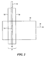
Fig. 2 shows a side view of the x-ray inspection system embodiments ofFig. 1 . - In accordance with embodiments of the present invention, beam cross talk is minimized between or among multiple flying-spot backscatter imaging systems configured as a multi-view backscatter inspection system, with no distance between the individual imaging systems. In other words, in a multi-view system comprised of individual backscatter imaging systems for each view, the individual imaging systems are substantially coplanar, while cross talk is advantageously reduced or eliminated.
- Methods and advantages of backscatter inspection of a moving vehicle by illuminating the vehicles with x-rays from either above or beneath the moving vehicle are described in
US Patent No. 6,249,567, issued June 19, 2001 . In accordance with preferred embodiments of the present invention, regions of enhanced backscatter that arise due to materials concealed close to the side walls of a vehicle are revealed without requiring that penetrating radiation traverse the vehicle during the course of inspection. -
Fig. 1 shows a schematic cross-sectional view of the elements of an inspection system, designated generally bynumeral 10. An object ofinspection 18, which may be animate or inanimate, moves, or is moved, in a direction into, or out of, the page and thus traverses aportal 12. Portal 12 supports a plurality ofsources Sources source 13 emits penetrating radiation in abeam 23 having a cross-section of a specified shape. For scatter imaging applications, a narrow pencil beam is typically employed.Beam 23 of penetrating radiation, may be, for example, a beam of x-rays such as a polychromatic x-ray beam. Whilesource 13 of penetrating radiation is preferably an x-ray tube, for example, however other sources of penetrating radiation, such as a linac (linear accelerator), are within the scope of the present invention, and, indeed, the penetrating radiation is not limited to x-ray radiation and may include gamma ray radiation. - A scanning mechanism is provided for
scanning beam 23 along a substantially vertical axis, such that, during a portion of a duty cycle,beam 23 is directed in a series of directions such as 24.Object 18 that is to be inspected moves pastbeam 23 in a substantially horizontal direction, into the page, in the depiction ofFig. 1 . In alternate embodiments of the invention, the source and/or other portions of the inspection system may be moved in relation toobject 18, which may be moving itself, or stationary. -
Source 13 may include a scanning mechanism such as a flying spot rotating chopper wheel as known to persons skilled in the art. Alternatively, electromagnetic scanners may be employed, such as those described inU.S. Patent No. 6,421,420, issued July 23, 2002 and entitled "Method and Apparatus for Generating Sequential Beams of Penetrating Radiation". - Beams of
sources object 18, which, as discussed, may refer to a vehicle, a container, or a person, for example, may be self-propelled through beams 23-28 or may be conveyed by a mechanized conveyor or pulled by a tractor, etc. In alternate embodiments of the invention, the inspection system, configured, for example, as a portal, may move, or be moved, over an object such as a vehicle that may, itself, be moving or stationary. - Beams 23-28 will be referred to in the present description, without limitation, as x-ray beams. In accordance with preferred embodiments of the invention, a rotating chopper wheel is used to develop a pencil beam 23-28 which may be swept in a plane substantially parallel to that of the page. The cross section of
pencil beam 23 is of comparable extent in each dimension and is typically substantially circular, although it may be many shapes. The dimensions of pencil beam 23-28 typically define the scatter image resolution which may be obtained with the system. Other shapes of beam cross section may be advantageously employed in particular applications. - A detector arrangement, typified by
scatter detector 31, is disposed in a plane parallel to the direction of motion ofobject 18 during the course of the scan.X-rays 30 scattered by Compton scattering out ofbeam 24 in an essentially backward direction are detected by one ormore backscatter detectors 31 disposed betweensource 13 andobject 18.Additional detector arrangements beam 24 and similarly, as will presently be described, for each of the other beams incident, in turn, on inspectedobject 18. - Additionally, transmission detectors disposed distally to the inspected
object 18 with respect to the emitting source may be used to augment the scatter image or images with an image of the object as obtained in transmitted x-rays, for example, the detector elements designated 35 and 36 detect the emission ofsource 13 as transmitted through the inspected object. In another embodiment of the invention, a single separate detector is disposed between the pair ofscatter detectors 35 and the pair ofscatter detectors 36 and is employed for detection of penetrating radiation transmitted throughobject 18. - Within the scope of the invention, any x-ray detection technology known in the art may be employed for the detector arrangements 31-36. The detectors may be scintillation materials, either solid or liquid or gaseous, viewed by photo-sensitive detectors such as photomultipliers or solid state detectors. Liquid scintillators may be doped with tin or other element or elements of high atomic number. Respective output signals from the scatter detectors 31-36 are transmitted to a
processor 40, and processed to obtain images offeature 42 inside the inspectedobject 18. Since incident x-ray photons are scattered by scattering sources withinobject 18 into all directions, detectors with large areas are used to maximize the collection of the scattered photons. In accordance with certain embodiments of the invention, processor 40 (otherwise referred to herein as a 'controller') may also be employed to derive other characteristics of the scattering object, such as its mass, mass density, effective atomic number, etc., all as known in the art. - In order to allow views of the inspected object from multiple directions, multiple sources 13-17 are used to irradiate the inspected object. However, since the photons emitted by each source are scattered in all directions, care must be exercised in order to eliminate cross-talk, i.e., the misidentification of the source of irradiation. In accordance with embodiments of the present invention, cross talk is advantageously reduced or eliminated by ensuring that only one imager is emitting radiation at a time. First, the duty-cycle of the beams emitted from the imaging systems is set less-than or equal-to the inverse of the number of imaging systems, or views, in the multi-view system. For example, if the number of views desired is six, each imaging system is set for a duty cycle of 1/6, or less.
- Next, the phase relationship between each pair of adjacent sources is set to 2π times the duty cycle. This results in sequenced radiation emission from the imagers, eliminating the possibility of concurrent emission from more than one imager. For example, a multi-view inspection system with 6 sources would require that they run at the same frequency, that their duty-cycles be 1/6, and that their phase relationship be 2π/6, or 60 degrees.
- In cases where flying-spot systems are realized by mechanical means such as rotating hoops and chopper wheels, these aforesaid criteria may be met by synchronization of the motion of the mechanical chopper elements, biased by phase offsets. Thus, for example, where collimators are rotated to define the path of
emergent x-ray beam 23, close-loop motion controller systems known in the art may be employed to drive the rotation of the collimators. The duty cycle is controlled by setting the fan aperture (the total sweep angle of a beam, i.e., the angle betweenextremal beams - By virtue of temporal sequencing which reduces or eliminates cross-talk, sources can be placed in a single plane, which advantageously permits virtually simultaneous on/off control of the x-rays regardless of the speed with which the object is passing by the imagers.
- The system described may advantageously provide for an image to be derived from the perspective of each successive source 13-17.
Fig. 1 shows an exemplary three-view system, withbeams - The beams from each imager sweep in sequence, such that no more than one imager is emitting radiation at a time. Thus, source (or 'imager') 13 sweeps its beam first. Radiation scattered from the object, as represented by
rays 44, is received by all of the detectors. The signals from each of the detectors are acquired as separate channels by an acquisition system. This process is repeated for each of the three imagers, creating "slices" of the object as it moves by. - Referring now to
Fig. 2 , a side view is shown of the arrangement ofFig. 1 , with elements designated by corresponding numbers. Aslot 50 is shown through which the beam ofsource 13 passes throughsegments detector 31 asobject 18 is scanned while moving in alateral direction 16. - The signals from the detectors can be selectively used to reconstruct an image of the object. Since
scattered photons 44 detected bydetectors 33 and 34 fromsource 13 are as useful as scattered photons fromsource 17, these same detectors can be shared among all sources, and result in improved scatter collection with efficient use of the detector hardware. - Embodiments of this invention, furthermore, may advantageously allow multi-view Flying-Spot X-ray Scatter imaging to be practiced in a smaller operational footprint by eliminating cross talk, and by allowing closer positioning of the individual imagers for each view. The coplanar positioning of these imagers (where an "imager" refers to a source, at least one detector, and associated electronics and signal processing) allows sharing of scatter detectors between, or among, imagers, allowing more scatter collection for improved image quality, with efficient use of detector hardware.
- In applications where scanning of selective regions of the object is desired, co-planar positioning of the imagers allows simultaneous on/off control of the x-rays regardless of the speed with which the object is passing by the imagers. This greatly simplifies the design of the control of x-ray emissions from each imager in the multi-view inspection system, thus individual sequencing of x-ray emissions need not be performed as is typically practiced in systems in which emission is not co-planar.
- Besides imaging contents of concealing enclosures, in terms of which embodiments of the present invention have been described, other characteristics of inspected objects may be obtained within the scope of the present invention. For example, backscatter techniques may be applied, as known in the art, for deriving mass, mass density, mass distribution, mean atomic number, or likelihood of containing targeted threat material.
- In accordance with certain embodiments of the invention, x-rays having maximal energies in the range between 160 keV and 300 keV are employed. At this energy, x-rays penetrate into a vehicle, and organic objects inside the vehicle can be detected. Since lower doses of x-ray irradiation are thus possible, automobiles may be scanned using the present invention. For applications where the scanned vehicle may contain personnel, end point energies below 300 keV are preferred. The scope of the present invention, however, is not limited by the range of penetrating photons employed.
- The described embodiments of the invention are intended to be merely exemplary and numerous variations and modifications will be apparent to those skilled in the art. All such variations and modifications are intended to be within the scope of the present invention as defined in the appended claims.
Claims (11)
- An inspection system for inspecting an object in motion in a direction with respect to the inspection system, the system comprising:(a) a first source for providing a first beam of penetrating radiation of specified cross-section;(b) a beam scanning mechanism, which is a rotating chopping wheel or an electromagnetic scanner, for scanning the first beam about a first beam direction substantially transverse to the direction of motion of the object;(c) a second source for providing a second beam of penetrating radiation of specified cross-section;(d) a beam scanning mechanism, which is a rotating chopping wheel or an electromagnetic scanner, for scanning the second beam about a second beam direction substantially coplanar with and substantially perpendicular to the first beam direction and temporally interspersed with the first beam of penetrating radiation;(e) a plurality of scatter detectors each scatter detector of which is disposed so as to detect radiation scattered from both the first beam and the second beam by any scattering material within the inspected object and for generating a scattered radiation signals
and(f) a controller for creating an image of the scattering material based at least on the scattered radiation signal. - An inspection system as claimed in claim 1 wherein the inspection system is fixed with respect to a local frame of reference.
- An inspection system as claimed in claim 1 wherein the inspection system is in motion, during the course of inspection, with respect to a local frame of reference.
- An inspection system as claimed in claim 1 wherein the first source of penetrating radiation is an x-ray source.
- An inspection system as claimed in claim 1 wherein the first beam of penetrating radiation is a pencil beam.
- An inspection system as claimed in claim 1 wherein emission of penetrating radiation in the first beam is characterized by a first temporal period and emission of penetrating radiation in the second beam is characterized by second temporal period, the first and the second temporal periods offset by fixed phase relationship.
- An inspection system as claimed in claim 6 wherein the temporal period of each source is characterized by a duty cycle.
- An inspection system as claimed in claim 7 wherein the temporal period of each source is characterized by phase relationship with respect to an adjacent source equal to 2π times the duty cycle.
- An inspection system as claimed in claim 1 wherein it further comprises a display for displaying a scatter image of material disposed within the object.
- An inspection system as claimed in claim 1 wherein it further comprises at least one transmission detector for detecting at least one of the first beam and the second beam as transmitted through the inspected object and for generating a transmitted radiation signals.
- A method for inspecting an object, the method comprising:(a) illuminating the object with penetrating radiation formed into a first beam scanned by a beam scanning mechanism, which is a rotating chopping wheel or an electromagnetic scanner, about a first beam direction substantially transverse to a direction of motion of the object;(b) illuminating the object with penetrating radiation formed into a second beam scanned by a beam scanning mechanism, which is a rotating chopping wheel or an electromagnetic scanner, about a second beam direction substantially transverse to the direction of motion of the object, the second beam direction substantially coplanar with the first beam direction, at a fixed and substantially perpendicular orientation with respect to the first beam direction, and temporally interspersed with respect to the first heam;(c) detecting radiation from the first beam and the second beam scattered by the object with a plurality of scatter detectors each scatter detector of which is disposed so as to detect scattering from both the first beam and the second beam to generate a scattered radiation signal;
and(d) characterizing the object on the basis of the scattered radiation signal.
Priority Applications (1)
| Application Number | Priority Date | Filing Date | Title |
|---|---|---|---|
| PL05743513T PL1733213T3 (en) | 2004-04-09 | 2005-04-01 | Eliminating cross-talk in a backscatter inspection portal comprising multiples sources by ensuring that only one source is emitting radiation at a time |
Applications Claiming Priority (2)
| Application Number | Priority Date | Filing Date | Title |
|---|---|---|---|
| US56107904P | 2004-04-09 | 2004-04-09 | |
| PCT/US2005/011382 WO2005098400A2 (en) | 2004-04-09 | 2005-04-01 | Eliminating cross-talk in a backscatter inspection portal comprising multiples sources by ensuring that only one source is emitting radiation at a time |
Publications (2)
| Publication Number | Publication Date |
|---|---|
| EP1733213A2 EP1733213A2 (en) | 2006-12-20 |
| EP1733213B1 true EP1733213B1 (en) | 2010-02-24 |
Family
ID=34968330
Family Applications (1)
| Application Number | Title | Priority Date | Filing Date |
|---|---|---|---|
| EP05743513A Active EP1733213B1 (en) | 2004-04-09 | 2005-04-01 | Eliminating cross-talk in a backscatter inspection portal comprising multiples sources by ensuring that only one source is emitting radiation at a time |
Country Status (16)
| Country | Link |
|---|---|
| US (2) | US7400701B1 (en) |
| EP (1) | EP1733213B1 (en) |
| JP (2) | JP4689663B2 (en) |
| KR (1) | KR101000182B1 (en) |
| CN (1) | CN1947001B (en) |
| AT (1) | ATE458994T1 (en) |
| DE (1) | DE602005019552D1 (en) |
| DK (1) | DK1733213T3 (en) |
| ES (1) | ES2338899T3 (en) |
| HK (1) | HK1104181A1 (en) |
| IL (1) | IL178284A (en) |
| NO (1) | NO20064614L (en) |
| PL (1) | PL1733213T3 (en) |
| PT (1) | PT1733213E (en) |
| RU (1) | RU2444723C2 (en) |
| WO (1) | WO2005098400A2 (en) |
Cited By (4)
| Publication number | Priority date | Publication date | Assignee | Title |
|---|---|---|---|---|
| US8929509B2 (en) | 2002-07-23 | 2015-01-06 | Rapiscan Systems, Inc. | Four-sided imaging system and method for detection of contraband |
| US9057679B2 (en) | 2012-02-03 | 2015-06-16 | Rapiscan Systems, Inc. | Combined scatter and transmission multi-view imaging system |
| US9223049B2 (en) | 2002-07-23 | 2015-12-29 | Rapiscan Systems, Inc. | Cargo scanning system with boom structure |
| US10317566B2 (en) | 2013-01-31 | 2019-06-11 | Rapiscan Systems, Inc. | Portable security inspection system |
Families Citing this family (101)
| Publication number | Priority date | Publication date | Assignee | Title |
|---|---|---|---|---|
| US8275091B2 (en) | 2002-07-23 | 2012-09-25 | Rapiscan Systems, Inc. | Compact mobile cargo scanning system |
| US9958569B2 (en) | 2002-07-23 | 2018-05-01 | Rapiscan Systems, Inc. | Mobile imaging system and method for detection of contraband |
| US8223919B2 (en) | 2003-04-25 | 2012-07-17 | Rapiscan Systems, Inc. | X-ray tomographic inspection systems for the identification of specific target items |
| US8451974B2 (en) | 2003-04-25 | 2013-05-28 | Rapiscan Systems, Inc. | X-ray tomographic inspection system for the identification of specific target items |
| US8837669B2 (en) | 2003-04-25 | 2014-09-16 | Rapiscan Systems, Inc. | X-ray scanning system |
| US9113839B2 (en) | 2003-04-25 | 2015-08-25 | Rapiscon Systems, Inc. | X-ray inspection system and method |
| US8243876B2 (en) | 2003-04-25 | 2012-08-14 | Rapiscan Systems, Inc. | X-ray scanners |
| GB0525593D0 (en) | 2005-12-16 | 2006-01-25 | Cxr Ltd | X-ray tomography inspection systems |
| US7949101B2 (en) | 2005-12-16 | 2011-05-24 | Rapiscan Systems, Inc. | X-ray scanners and X-ray sources therefor |
| US6928141B2 (en) | 2003-06-20 | 2005-08-09 | Rapiscan, Inc. | Relocatable X-ray imaging system and method for inspecting commercial vehicles and cargo containers |
| US7809109B2 (en) * | 2004-04-09 | 2010-10-05 | American Science And Engineering, Inc. | Multiple image collection and synthesis for personnel screening |
| US7471764B2 (en) | 2005-04-15 | 2008-12-30 | Rapiscan Security Products, Inc. | X-ray imaging system having improved weather resistance |
| EP2392947A3 (en) * | 2005-07-05 | 2014-02-12 | L-3 Communications Security and Detection Systems, Inc. | Methods and apparatus for e-beam scanning |
| US7526064B2 (en) | 2006-05-05 | 2009-04-28 | Rapiscan Security Products, Inc. | Multiple pass cargo inspection system |
| KR101034753B1 (en) * | 2006-08-11 | 2011-05-17 | 아메리칸 사이언스 앤 엔지니어링, 인크. | X-ray inspection with contemporaneous and proximal transmission and backscatter imaging |
| US7492861B2 (en) * | 2006-10-13 | 2009-02-17 | Tsinghua University | Apparatus and method for quick imaging and inspecting moving target |
| US8995619B2 (en) | 2010-03-14 | 2015-03-31 | Rapiscan Systems, Inc. | Personnel screening system |
| US7796733B2 (en) * | 2007-02-01 | 2010-09-14 | Rapiscan Systems, Inc. | Personnel security screening system with enhanced privacy |
| US8576982B2 (en) | 2008-02-01 | 2013-11-05 | Rapiscan Systems, Inc. | Personnel screening system |
| US8638904B2 (en) | 2010-03-14 | 2014-01-28 | Rapiscan Systems, Inc. | Personnel screening system |
| US20080253526A1 (en) * | 2007-04-11 | 2008-10-16 | Searete Llc, A Limited Liability Corporation Of The State Of Delaware | Geometric compton scattered x-ray visualizing, imaging, or information providing |
| US8041006B2 (en) * | 2007-04-11 | 2011-10-18 | The Invention Science Fund I Llc | Aspects of compton scattered X-ray visualization, imaging, or information providing |
| US20080253525A1 (en) * | 2007-04-11 | 2008-10-16 | Boyden Edward S | Compton scattered x-ray visualizing, imaging, or information providing of at least some dissimilar matter |
| US8837677B2 (en) * | 2007-04-11 | 2014-09-16 | The Invention Science Fund I Llc | Method and system for compton scattered X-ray depth visualization, imaging, or information provider |
| US20080253522A1 (en) * | 2007-04-11 | 2008-10-16 | Searete Llc, A Limited Liability Corporation Of The State Of Delaware | Tool associated with compton scattered X-ray visualization, imaging, or information provider |
| US7711089B2 (en) * | 2007-04-11 | 2010-05-04 | The Invention Science Fund I, Llc | Scintillator aspects of compton scattered X-ray visualization, imaging, or information providing |
| US7742567B2 (en) * | 2007-04-11 | 2010-06-22 | Searete Llc | Compton scattered X-ray visualization, imaging, or information provider with time of flight computation |
| CN103064125B (en) | 2007-06-21 | 2016-01-20 | 瑞皮斯坎系统股份有限公司 | For improving the system and method for the people screening guided |
| BRPI0821603B1 (en) * | 2007-12-25 | 2019-05-07 | Rapiscan Systems, Inc | IMAGE TRAINING APPARATUS FOR DETECTION OF A HIDDEN OBJECT CARRIED IN A HUMAN BODY |
| GB0803641D0 (en) | 2008-02-28 | 2008-04-02 | Rapiscan Security Products Inc | Scanning systems |
| GB0809107D0 (en) * | 2008-05-20 | 2008-06-25 | Rapiscan Security Products Inc | Scannign systems |
| GB0809109D0 (en) | 2008-05-20 | 2008-06-25 | Rapiscan Security Products Inc | Scanner systems |
| GB0809110D0 (en) | 2008-05-20 | 2008-06-25 | Rapiscan Security Products Inc | Gantry scanner systems |
| US8963094B2 (en) | 2008-06-11 | 2015-02-24 | Rapiscan Systems, Inc. | Composite gamma-neutron detection system |
| GB0810638D0 (en) | 2008-06-11 | 2008-07-16 | Rapiscan Security Products Inc | Photomultiplier and detection systems |
| US8130904B2 (en) | 2009-01-29 | 2012-03-06 | The Invention Science Fund I, Llc | Diagnostic delivery service |
| US8047714B2 (en) | 2009-01-29 | 2011-11-01 | The Invention Science Fund I, Llc | Diagnostic delivery service |
| US9310323B2 (en) | 2009-05-16 | 2016-04-12 | Rapiscan Systems, Inc. | Systems and methods for high-Z threat alarm resolution |
| US8275092B1 (en) | 2009-06-15 | 2012-09-25 | American Science And Engineering, Inc. | Three-dimensional mapping based on scattered penetrating radiation |
| CN102484935B (en) * | 2009-07-13 | 2015-02-04 | 拉皮斯坎系统股份有限公司 | Four-sided imaging system and method for detection of contraband |
| WO2011011583A1 (en) * | 2009-07-24 | 2011-01-27 | Nucsafe, Inc. | Spatial sequenced backscatter portal |
| WO2011014445A1 (en) * | 2009-07-29 | 2011-02-03 | American Science And Engineering, Inc. | Top-down x-ray inspection trailer |
| US8824632B2 (en) | 2009-07-29 | 2014-09-02 | American Science And Engineering, Inc. | Backscatter X-ray inspection van with top-down imaging |
| US20110142201A1 (en) * | 2009-12-15 | 2011-06-16 | General Electric Company | Multi-view imaging system and method |
| GB2494963B (en) | 2010-03-14 | 2017-02-22 | Rapiscan Systems Inc | Multiple screen detection systems |
| US9036782B2 (en) * | 2010-08-06 | 2015-05-19 | Telesecurity Sciences, Inc. | Dual energy backscatter X-ray shoe scanning device |
| US8848871B2 (en) * | 2010-11-04 | 2014-09-30 | Ut-Battelle, Llc | X-ray backscatter imaging of nuclear materials |
| PL2673623T3 (en) | 2011-02-08 | 2020-12-28 | American Science & Engineering, Inc. | Backscatter energy analysis for classification of materials based on positional non-commutativity |
| US8908831B2 (en) | 2011-02-08 | 2014-12-09 | Rapiscan Systems, Inc. | Covert surveillance using multi-modality sensing |
| WO2012109273A2 (en) | 2011-02-08 | 2012-08-16 | Rapiscan Systems, Inc. | Covert surveillance using multi-modality sensing |
| JP5423705B2 (en) * | 2011-02-28 | 2014-02-19 | 横河電機株式会社 | Radiation inspection equipment |
| US9218933B2 (en) | 2011-06-09 | 2015-12-22 | Rapidscan Systems, Inc. | Low-dose radiographic imaging system |
| US8761338B2 (en) | 2011-06-20 | 2014-06-24 | The Boeing Company | Integrated backscatter X-ray system |
| US9151721B2 (en) | 2011-06-20 | 2015-10-06 | The Boeing Company | Integrated backscatter X-ray system |
| CN102393399B (en) * | 2011-08-24 | 2015-10-28 | 屈俊健 | The forming apparatus of X ray flying spot and method |
| KR102067367B1 (en) | 2011-09-07 | 2020-02-11 | 라피스캔 시스템스, 인코포레이티드 | X-ray inspection method that integrates manifest data with imaging/detection processing |
| US8855268B1 (en) * | 2011-11-01 | 2014-10-07 | The Boeing Company | System for inspecting objects underwater |
| US10670740B2 (en) | 2012-02-14 | 2020-06-02 | American Science And Engineering, Inc. | Spectral discrimination using wavelength-shifting fiber-coupled scintillation detectors |
| ES1153636Y (en) | 2012-02-14 | 2016-07-08 | American Science & Eng Inc | X-ray inspection device to inspect the underside of a vehicle |
| CN103308535B (en) * | 2012-03-09 | 2016-04-13 | 同方威视技术股份有限公司 | For equipment and the method for ray scanning imaging |
| US9123450B2 (en) | 2012-04-30 | 2015-09-01 | The Boeing Company | Single beam backscatter x-ray system |
| US8879688B2 (en) * | 2012-05-22 | 2014-11-04 | The Boeing Company | Reconfigurable detector system |
| CN103901494B (en) * | 2012-12-27 | 2017-08-29 | 同方威视技术股份有限公司 | Human body back scattering safe examination system and its method |
| US9778391B2 (en) * | 2013-03-15 | 2017-10-03 | Varex Imaging Corporation | Systems and methods for multi-view imaging and tomography |
| EP3025147A4 (en) | 2013-07-23 | 2017-03-22 | Rapiscan Systems, Inc. | Methods for improving processing speed for object inspection |
| CN104340627B (en) * | 2013-07-23 | 2017-03-01 | 同方威视技术股份有限公司 | Vehicle drive system, vehicle double mode by system with inspection system |
| US9519853B2 (en) | 2013-11-01 | 2016-12-13 | James P Tolle | Wearable, non-visible identification device for friendly force identification and intruder detection |
| US9557427B2 (en) | 2014-01-08 | 2017-01-31 | Rapiscan Systems, Inc. | Thin gap chamber neutron detectors |
| RO130582B1 (en) * | 2014-01-23 | 2021-12-30 | Mb Telecom Ltd. S.R.L. | System and method for complete and non-intrusive inspection of aircrafts |
| MX361149B (en) | 2014-03-07 | 2018-11-28 | Rapiscan Systems Inc | Ultra wide band detectors. |
| US11280898B2 (en) | 2014-03-07 | 2022-03-22 | Rapiscan Systems, Inc. | Radar-based baggage and parcel inspection systems |
| WO2015175751A1 (en) | 2014-05-16 | 2015-11-19 | American Science And Engineering, Inc. | Source for intra-pulse multi-energy x-ray cargo inspection |
| US11266006B2 (en) | 2014-05-16 | 2022-03-01 | American Science And Engineering, Inc. | Method and system for timing the injections of electron beams in a multi-energy x-ray cargo inspection system |
| WO2016003547A1 (en) | 2014-06-30 | 2016-01-07 | American Science And Engineering, Inc. | Rapidly relocatable modular cargo container scanner |
| CN104101910A (en) * | 2014-07-04 | 2014-10-15 | 清华大学 | Distributed radiation source-based X-ray backscattering channel type vehicle security system and method |
| CN104062688A (en) * | 2014-07-04 | 2014-09-24 | 同方威视技术股份有限公司 | X-ray back scattering channel type vehicle security check system and method based on distributed radiation sources |
| US9594033B2 (en) | 2014-07-22 | 2017-03-14 | The Boeing Company | Visible X-ray indication and detection system for X-ray backscatter applications |
| MX2017006913A (en) | 2014-11-25 | 2017-11-30 | Rapiscan Systems Inc | Intelligent security management system. |
| EP3271709B1 (en) | 2015-03-20 | 2022-09-21 | Rapiscan Systems, Inc. | Hand-held portable backscatter inspection system |
| WO2017015549A1 (en) * | 2015-07-22 | 2017-01-26 | UHV Technologies, Inc. | X-ray imaging and chemical analysis of plant roots |
| US9989483B2 (en) * | 2015-08-17 | 2018-06-05 | The Boeing Company | Systems and methods for performing backscatter three dimensional imaging from one side of a structure |
| US11536672B2 (en) | 2015-09-08 | 2022-12-27 | American Science And Engineering, Inc. | Systems and methods for using backscatter imaging in precision agriculture |
| US10955367B2 (en) | 2015-09-08 | 2021-03-23 | American Science And Engineering, Inc. | Backscatter imaging for precision agriculture |
| GB2559500B (en) | 2015-09-10 | 2022-02-23 | American Science & Eng Inc | Backscatter characterization using interlinearly adaptive electromagnetic x-ray scanning |
| US10345479B2 (en) | 2015-09-16 | 2019-07-09 | Rapiscan Systems, Inc. | Portable X-ray scanner |
| EP3420563A4 (en) | 2016-02-22 | 2020-03-11 | Rapiscan Systems, Inc. | Systems and methods for detecting threats and contraband in cargo |
| CN107280700B (en) * | 2016-03-31 | 2023-06-20 | 通用电气公司 | CT imaging equipment and method, X-ray receiving and transmitting assembly for CT imaging equipment |
| EP3520120A4 (en) | 2016-09-30 | 2020-07-08 | American Science & Engineering, Inc. | X-ray source for 2d scanning beam imaging |
| CN106526688A (en) * | 2016-12-28 | 2017-03-22 | 同方威视技术股份有限公司 | Back scattering inspection vehicle |
| CN110199373B (en) | 2017-01-31 | 2021-09-28 | 拉皮斯坎系统股份有限公司 | High power X-ray source and method of operation |
| CN106841256B (en) * | 2017-02-17 | 2023-11-21 | 清华大学 | Multi-view back-scattering inspection system and multi-view back-scattering inspection method |
| CN108227027B (en) * | 2017-12-29 | 2020-12-01 | 同方威视技术股份有限公司 | Vehicle-mounted backscatter inspection system |
| CN108008458B (en) * | 2017-12-29 | 2020-09-08 | 同方威视技术股份有限公司 | Vehicle-mounted backscatter inspection system |
| EP3811117A4 (en) | 2018-06-20 | 2022-03-16 | American Science & Engineering, Inc. | Wavelength-shifting sheet-coupled scintillation detectors |
| CN109521480A (en) * | 2019-01-04 | 2019-03-26 | 同方威视科技(北京)有限公司 | Radiation examination device and radiation testing method |
| US11212902B2 (en) | 2020-02-25 | 2021-12-28 | Rapiscan Systems, Inc. | Multiplexed drive systems and methods for a multi-emitter X-ray source |
| US11193898B1 (en) | 2020-06-01 | 2021-12-07 | American Science And Engineering, Inc. | Systems and methods for controlling image contrast in an X-ray system |
| US11175245B1 (en) | 2020-06-15 | 2021-11-16 | American Science And Engineering, Inc. | Scatter X-ray imaging with adaptive scanning beam intensity |
| US11340361B1 (en) | 2020-11-23 | 2022-05-24 | American Science And Engineering, Inc. | Wireless transmission detector panel for an X-ray scanner |
| GB2618277A (en) | 2021-02-23 | 2023-11-01 | Rapiscan Systems Inc | Systems and methods for eliminating cross-talk in scanning systems having multiple x-ray sources |
| WO2024030046A1 (en) * | 2022-08-01 | 2024-02-08 | Obshhestvo S Ogranichennoj Otvetstvennost`Yu "Indikom" (Ooo "Indikom") | Method for determining the spatial profile of inspected objects |
Family Cites Families (60)
| Publication number | Priority date | Publication date | Assignee | Title |
|---|---|---|---|---|
| DK131955C (en) * | 1973-10-09 | 1976-02-23 | I Leunbach | PROCEDURE AND SYSTEM FOR DETERMINING THE ELECTRONITY OF A PART VOLUME OF A BODY |
| US4064440A (en) * | 1976-06-22 | 1977-12-20 | Roder Frederick L | X-ray or gamma-ray examination device for moving objects |
| DE2939146A1 (en) * | 1979-09-27 | 1981-04-16 | Philips Patentverwaltung Gmbh, 2000 Hamburg | METHOD FOR EXAMINING A BODY WITH Pervasive RADIATION |
| US4525854A (en) * | 1983-03-22 | 1985-06-25 | Troxler Electronic Laboratories, Inc. | Radiation scatter apparatus and method |
| US4799247A (en) * | 1986-06-20 | 1989-01-17 | American Science And Engineering, Inc. | X-ray imaging particularly adapted for low Z materials |
| US4809312A (en) * | 1986-07-22 | 1989-02-28 | American Science And Engineering, Inc. | Method and apparatus for producing tomographic images |
| GB8623196D0 (en) | 1986-09-26 | 1986-10-29 | Robinson M | Visual screening system |
| DE8717508U1 (en) * | 1987-10-19 | 1989-01-05 | Heimann Gmbh, 6200 Wiesbaden, De | |
| US4825454A (en) * | 1987-12-28 | 1989-04-25 | American Science And Engineering, Inc. | Tomographic imaging with concentric conical collimator |
| US4864142A (en) * | 1988-01-11 | 1989-09-05 | Penetron, Inc. | Method and apparatus for the noninvasive interrogation of objects |
| US5179581A (en) * | 1989-09-13 | 1993-01-12 | American Science And Engineering, Inc. | Automatic threat detection based on illumination by penetrating radiant energy |
| US5022062A (en) * | 1989-09-13 | 1991-06-04 | American Science And Engineering, Inc. | Automatic threat detection based on illumination by penetrating radiant energy using histogram processing |
| US5181234B1 (en) * | 1990-08-06 | 2000-01-04 | Rapiscan Security Products Inc | X-ray backscatter detection system |
| US5247561A (en) * | 1991-01-02 | 1993-09-21 | Kotowski Andreas F | Luggage inspection device |
| JPH04344491A (en) * | 1991-05-21 | 1992-12-01 | Toshiba Corp | Radioscopic examining device |
| JPH05133909A (en) * | 1991-11-15 | 1993-05-28 | Toshiba Corp | Scattered radiation inspecting apparatus |
| GB9200828D0 (en) * | 1992-01-15 | 1992-03-11 | Image Research Ltd | Improvements in and relating to material identification using x-rays |
| DE4215343A1 (en) * | 1992-05-09 | 1993-11-11 | Philips Patentverwaltung | Filter method for an X-ray system and arrangement for carrying out such a filter method |
| JPH05323039A (en) * | 1992-05-21 | 1993-12-07 | Toshiba Corp | Radiation inspector |
| JPH06138252A (en) * | 1992-10-28 | 1994-05-20 | Toshiba Corp | X-ray inspection device |
| US5430787A (en) * | 1992-12-03 | 1995-07-04 | The United States Of America As Represented By The Secretary Of Commerce | Compton scattering tomography |
| US5600303A (en) * | 1993-01-15 | 1997-02-04 | Technology International Incorporated | Detection of concealed explosives and contraband |
| DE4311174C2 (en) | 1993-04-05 | 1996-02-15 | Heimann Systems Gmbh & Co | X-ray inspection system for containers and trucks |
| DE19532965C2 (en) * | 1995-09-07 | 1998-07-16 | Heimann Systems Gmbh & Co | X-ray inspection system for large-volume goods |
| US6018562A (en) * | 1995-11-13 | 2000-01-25 | The United States Of America As Represented By The Secretary Of The Army | Apparatus and method for automatic recognition of concealed objects using multiple energy computed tomography |
| US5764683B1 (en) * | 1996-02-12 | 2000-11-21 | American Science & Eng Inc | Mobile x-ray inspection system for large objects |
| US5696806A (en) * | 1996-03-11 | 1997-12-09 | Grodzins; Lee | Tomographic method of x-ray imaging |
| US5638420A (en) * | 1996-07-03 | 1997-06-10 | Advanced Research And Applications Corporation | Straddle inspection system |
| US5930326A (en) * | 1996-07-12 | 1999-07-27 | American Science And Engineering, Inc. | Side scatter tomography system |
| US5910973A (en) * | 1996-07-22 | 1999-06-08 | American Science And Engineering, Inc. | Rapid X-ray inspection system |
| US5763886A (en) * | 1996-08-07 | 1998-06-09 | Northrop Grumman Corporation | Two-dimensional imaging backscatter probe |
| US5974111A (en) * | 1996-09-24 | 1999-10-26 | Vivid Technologies, Inc. | Identifying explosives or other contraband by employing transmitted or scattered X-rays |
| US5940468A (en) | 1996-11-08 | 1999-08-17 | American Science And Engineering, Inc. | Coded aperture X-ray imaging system |
| US5912460A (en) | 1997-03-06 | 1999-06-15 | Schlumberger Technology Corporation | Method for determining formation density and formation photo-electric factor with a multi-detector-gamma-ray tool |
| EP1012586A2 (en) * | 1997-09-09 | 2000-06-28 | American Science & Engineering, Inc. | A tomographic inspection system |
| JPH11164829A (en) * | 1997-12-03 | 1999-06-22 | Toshiba Corp | Frame movable helical scanning ct apparatus |
| US6151381A (en) * | 1998-01-28 | 2000-11-21 | American Science And Engineering, Inc. | Gated transmission and scatter detection for x-ray imaging |
| US6094472A (en) * | 1998-04-14 | 2000-07-25 | Rapiscan Security Products, Inc. | X-ray backscatter imaging system including moving body tracking assembly |
| US6236709B1 (en) * | 1998-05-04 | 2001-05-22 | Ensco, Inc. | Continuous high speed tomographic imaging system and method |
| US6442233B1 (en) * | 1998-06-18 | 2002-08-27 | American Science And Engineering, Inc. | Coherent x-ray scatter inspection system with sidescatter and energy-resolved detection |
| RU2158917C2 (en) * | 1998-08-24 | 2000-11-10 | АОЗТ "Технологии металлургии" | Ore-controlling plant |
| US6130931A (en) * | 1998-09-17 | 2000-10-10 | Process Control, Inc. | X-ray fluorescence elemental analyzer |
| DE69924001T2 (en) * | 1998-11-30 | 2006-02-09 | American Science & Engineering, Inc., Billerica | X-RAY EXAMINATION SYSTEM WITH CONE AND PENCIL RADIATION FROM A COMMON SOURCE |
| US6421420B1 (en) * | 1998-12-01 | 2002-07-16 | American Science & Engineering, Inc. | Method and apparatus for generating sequential beams of penetrating radiation |
| US6249567B1 (en) | 1998-12-01 | 2001-06-19 | American Science & Engineering, Inc. | X-ray back scatter imaging system for undercarriage inspection |
| US6459764B1 (en) * | 1999-01-27 | 2002-10-01 | American Science And Engineering, Inc. | Drive-through vehicle inspection system |
| US6546072B1 (en) * | 1999-07-30 | 2003-04-08 | American Science And Engineering, Inc. | Transmission enhanced scatter imaging |
| US6567496B1 (en) * | 1999-10-14 | 2003-05-20 | Sychev Boris S | Cargo inspection apparatus and process |
| US6459761B1 (en) | 2000-02-10 | 2002-10-01 | American Science And Engineering, Inc. | Spectrally shaped x-ray inspection system |
| CA2348150C (en) * | 2000-05-25 | 2007-03-13 | Esam M.A. Hussein | Non-rotating x-ray system for three-dimensional, three-parameter imaging |
| RU2193185C2 (en) * | 2000-10-02 | 2002-11-20 | Общество с ограниченной ответственностью Научно-производственная фирма "ТАПЕКО" | Method of detection of diamonds on conveyer in flow or in specimen of diamond-bearing rock |
| US6473487B1 (en) * | 2000-12-27 | 2002-10-29 | Rapiscan Security Products, Inc. | Method and apparatus for physical characteristics discrimination of objects using a limited view three dimensional reconstruction |
| RU2225018C2 (en) * | 2002-04-22 | 2004-02-27 | Российский научный центр "Курчатовский институт" | Technique detecting objects in upper layers of ground, specifically, infantry mines |
| US6879657B2 (en) * | 2002-05-10 | 2005-04-12 | Ge Medical Systems Global Technology, Llc | Computed tomography system with integrated scatter detectors |
| US7162005B2 (en) * | 2002-07-19 | 2007-01-09 | Varian Medical Systems Technologies, Inc. | Radiation sources and compact radiation scanning systems |
| US7103137B2 (en) * | 2002-07-24 | 2006-09-05 | Varian Medical Systems Technology, Inc. | Radiation scanning of objects for contraband |
| JP2004108912A (en) * | 2002-09-18 | 2004-04-08 | Hitachi Ltd | Detecting apparatus using neutron and its method |
| JP4314008B2 (en) * | 2002-10-01 | 2009-08-12 | 株式会社東芝 | X-ray CT scanner |
| US7333587B2 (en) * | 2004-02-27 | 2008-02-19 | General Electric Company | Method and system for imaging using multiple offset X-ray emission points |
| US20070009088A1 (en) * | 2005-07-06 | 2007-01-11 | Edic Peter M | System and method for imaging using distributed X-ray sources |
-
2005
- 2005-04-01 DK DK05743513.3T patent/DK1733213T3/en active
- 2005-04-01 CN CN2005800122188A patent/CN1947001B/en active Active
- 2005-04-01 DE DE602005019552T patent/DE602005019552D1/en active Active
- 2005-04-01 RU RU2006133625/28A patent/RU2444723C2/en not_active Application Discontinuation
- 2005-04-01 PL PL05743513T patent/PL1733213T3/en unknown
- 2005-04-01 PT PT05743513T patent/PT1733213E/en unknown
- 2005-04-01 EP EP05743513A patent/EP1733213B1/en active Active
- 2005-04-01 ES ES05743513T patent/ES2338899T3/en active Active
- 2005-04-01 JP JP2007507407A patent/JP4689663B2/en active Active
- 2005-04-01 WO PCT/US2005/011382 patent/WO2005098400A2/en not_active Application Discontinuation
- 2005-04-01 US US11/097,092 patent/US7400701B1/en active Active
- 2005-04-01 KR KR1020067020552A patent/KR101000182B1/en active IP Right Grant
- 2005-04-01 AT AT05743513T patent/ATE458994T1/en not_active IP Right Cessation
-
2006
- 2006-09-25 IL IL178284A patent/IL178284A/en active IP Right Grant
- 2006-10-11 NO NO20064614A patent/NO20064614L/en not_active Application Discontinuation
-
2007
- 2007-08-16 HK HK07108948.9A patent/HK1104181A1/en unknown
-
2008
- 2008-07-10 US US12/171,020 patent/US7593506B2/en active Active
-
2010
- 2010-02-25 JP JP2010040967A patent/JP2010133977A/en not_active Withdrawn
Cited By (4)
| Publication number | Priority date | Publication date | Assignee | Title |
|---|---|---|---|---|
| US8929509B2 (en) | 2002-07-23 | 2015-01-06 | Rapiscan Systems, Inc. | Four-sided imaging system and method for detection of contraband |
| US9223049B2 (en) | 2002-07-23 | 2015-12-29 | Rapiscan Systems, Inc. | Cargo scanning system with boom structure |
| US9057679B2 (en) | 2012-02-03 | 2015-06-16 | Rapiscan Systems, Inc. | Combined scatter and transmission multi-view imaging system |
| US10317566B2 (en) | 2013-01-31 | 2019-06-11 | Rapiscan Systems, Inc. | Portable security inspection system |
Also Published As
| Publication number | Publication date |
|---|---|
| WO2005098400A3 (en) | 2005-11-24 |
| US7593506B2 (en) | 2009-09-22 |
| JP2010133977A (en) | 2010-06-17 |
| DE602005019552D1 (en) | 2010-04-08 |
| WO2005098400A2 (en) | 2005-10-20 |
| HK1104181A1 (en) | 2008-01-04 |
| CN1947001A (en) | 2007-04-11 |
| KR101000182B1 (en) | 2010-12-10 |
| CN1947001B (en) | 2011-04-20 |
| RU2444723C2 (en) | 2012-03-10 |
| RU2006133625A (en) | 2008-03-27 |
| IL178284A (en) | 2010-12-30 |
| JP2007532876A (en) | 2007-11-15 |
| US7400701B1 (en) | 2008-07-15 |
| US20080310591A1 (en) | 2008-12-18 |
| PT1733213E (en) | 2010-05-27 |
| JP4689663B2 (en) | 2011-05-25 |
| ES2338899T3 (en) | 2010-05-13 |
| ATE458994T1 (en) | 2010-03-15 |
| PL1733213T3 (en) | 2010-07-30 |
| KR20060132990A (en) | 2006-12-22 |
| US20080152081A1 (en) | 2008-06-26 |
| EP1733213A2 (en) | 2006-12-20 |
| IL178284A0 (en) | 2006-12-31 |
| DK1733213T3 (en) | 2010-05-03 |
| NO20064614L (en) | 2007-01-09 |
Similar Documents
| Publication | Publication Date | Title |
|---|---|---|
| EP1733213B1 (en) | Eliminating cross-talk in a backscatter inspection portal comprising multiples sources by ensuring that only one source is emitting radiation at a time | |
| US7103137B2 (en) | Radiation scanning of objects for contraband | |
| EP1579245B1 (en) | Radiation scanning units including a movable platform | |
| US6453007B2 (en) | X-ray inspection using co-planar pencil and fan beams | |
| US7672426B2 (en) | Radiation scanning units with reduced detector requirements | |
| US7869566B2 (en) | Integrated multi-sensor systems for and methods of explosives detection | |
| US6192104B1 (en) | Fan and pencil beams from a common source for x-ray inspection | |
| EP0852717B1 (en) | Detecting contraband by employing interactive multiprobe tomography | |
| EP2963455B1 (en) | X-ray backscattering safety inspection system having distributed x-ray source and method using the same | |
| CN109691238B (en) | System and method for improving penetration of a radiological imaging scanner | |
| CN101501530A (en) | System and method for acquiring image data | |
| MXPA06011443A (en) | Eliminating cross-talk in a backscatter inspection portal comprising multiples sources by ensuring that only one source is emitting radiation at a time |
Legal Events
| Date | Code | Title | Description |
|---|---|---|---|
| PUAI | Public reference made under article 153(3) epc to a published international application that has entered the european phase |
Free format text: ORIGINAL CODE: 0009012 |
|
| 17P | Request for examination filed |
Effective date: 20060809 |
|
| AK | Designated contracting states |
Kind code of ref document: A2 Designated state(s): AT BE BG CH CY CZ DE DK EE ES FI FR GB GR HU IE IS IT LI LT LU MC NL PL PT RO SE SI SK TR |
|
| 17Q | First examination report despatched |
Effective date: 20070205 |
|
| DAX | Request for extension of the european patent (deleted) | ||
| GRAP | Despatch of communication of intention to grant a patent |
Free format text: ORIGINAL CODE: EPIDOSNIGR1 |
|
| GRAS | Grant fee paid |
Free format text: ORIGINAL CODE: EPIDOSNIGR3 |
|
| GRAA | (expected) grant |
Free format text: ORIGINAL CODE: 0009210 |
|
| AK | Designated contracting states |
Kind code of ref document: B1 Designated state(s): AT BE BG CH CY CZ DE DK EE ES FI FR GB GR HU IE IS IT LI LT LU MC NL PL PT RO SE SI SK TR |
|
| REG | Reference to a national code |
Ref country code: GB Ref legal event code: FG4D |
|
| REG | Reference to a national code |
Ref country code: CH Ref legal event code: EP |
|
| REG | Reference to a national code |
Ref country code: CH Ref legal event code: NV Representative=s name: KIRKER & CIE S.A. |
|
| REG | Reference to a national code |
Ref country code: IE Ref legal event code: FG4D |
|
| REF | Corresponds to: |
Ref document number: 602005019552 Country of ref document: DE Date of ref document: 20100408 Kind code of ref document: P |
|
| REG | Reference to a national code |
Ref country code: GR Ref legal event code: EP Ref document number: 20100400778 Country of ref document: GR |
|
| REG | Reference to a national code |
Ref country code: DK Ref legal event code: T3 |
|
| REG | Reference to a national code |
Ref country code: SE Ref legal event code: TRGR |
|
| REG | Reference to a national code |
Ref country code: ES Ref legal event code: FG2A Ref document number: 2338899 Country of ref document: ES Kind code of ref document: T3 |
|
| REG | Reference to a national code |
Ref country code: NL Ref legal event code: T3 |
|
| REG | Reference to a national code |
Ref country code: PT Ref legal event code: SC4A Free format text: AVAILABILITY OF NATIONAL TRANSLATION Effective date: 20100520 |
|
| LTIE | Lt: invalidation of european patent or patent extension |
Effective date: 20100224 |
|
| PG25 | Lapsed in a contracting state [announced via postgrant information from national office to epo] |
Ref country code: LT Free format text: LAPSE BECAUSE OF FAILURE TO SUBMIT A TRANSLATION OF THE DESCRIPTION OR TO PAY THE FEE WITHIN THE PRESCRIBED TIME-LIMIT Effective date: 20100224 Ref country code: IS Free format text: LAPSE BECAUSE OF FAILURE TO SUBMIT A TRANSLATION OF THE DESCRIPTION OR TO PAY THE FEE WITHIN THE PRESCRIBED TIME-LIMIT Effective date: 20100624 |
|
| REG | Reference to a national code |
Ref country code: PL Ref legal event code: T3 |
|
| PG25 | Lapsed in a contracting state [announced via postgrant information from national office to epo] |
Ref country code: SI Free format text: LAPSE BECAUSE OF FAILURE TO SUBMIT A TRANSLATION OF THE DESCRIPTION OR TO PAY THE FEE WITHIN THE PRESCRIBED TIME-LIMIT Effective date: 20100224 |
|
| PG25 | Lapsed in a contracting state [announced via postgrant information from national office to epo] |
Ref country code: EE Free format text: LAPSE BECAUSE OF FAILURE TO SUBMIT A TRANSLATION OF THE DESCRIPTION OR TO PAY THE FEE WITHIN THE PRESCRIBED TIME-LIMIT Effective date: 20100224 Ref country code: RO Free format text: LAPSE BECAUSE OF FAILURE TO SUBMIT A TRANSLATION OF THE DESCRIPTION OR TO PAY THE FEE WITHIN THE PRESCRIBED TIME-LIMIT Effective date: 20100224 Ref country code: CY Free format text: LAPSE BECAUSE OF FAILURE TO SUBMIT A TRANSLATION OF THE DESCRIPTION OR TO PAY THE FEE WITHIN THE PRESCRIBED TIME-LIMIT Effective date: 20100224 |
|
| BERE | Be: lapsed |
Owner name: AMERICAN SCIENCE & ENGINEERING, INC. Effective date: 20100430 |
|
| PG25 | Lapsed in a contracting state [announced via postgrant information from national office to epo] |
Ref country code: MC Free format text: LAPSE BECAUSE OF NON-PAYMENT OF DUE FEES Effective date: 20100430 Ref country code: SK Free format text: LAPSE BECAUSE OF FAILURE TO SUBMIT A TRANSLATION OF THE DESCRIPTION OR TO PAY THE FEE WITHIN THE PRESCRIBED TIME-LIMIT Effective date: 20100224 |
|
| PLBE | No opposition filed within time limit |
Free format text: ORIGINAL CODE: 0009261 |
|
| STAA | Information on the status of an ep patent application or granted ep patent |
Free format text: STATUS: NO OPPOSITION FILED WITHIN TIME LIMIT |
|
| REG | Reference to a national code |
Ref country code: DK Ref legal event code: EBP |
|
| PG25 | Lapsed in a contracting state [announced via postgrant information from national office to epo] |
Ref country code: IE Free format text: LAPSE BECAUSE OF NON-PAYMENT OF DUE FEES Effective date: 20100401 |
|
| 26N | No opposition filed |
Effective date: 20101125 |
|
| PG25 | Lapsed in a contracting state [announced via postgrant information from national office to epo] |
Ref country code: CZ Free format text: LAPSE BECAUSE OF NON-PAYMENT OF DUE FEES Effective date: 20100401 |
|
| PG25 | Lapsed in a contracting state [announced via postgrant information from national office to epo] |
Ref country code: GR Free format text: LAPSE BECAUSE OF NON-PAYMENT OF DUE FEES Effective date: 20101103 Ref country code: BE Free format text: LAPSE BECAUSE OF NON-PAYMENT OF DUE FEES Effective date: 20100430 |
|
| PG25 | Lapsed in a contracting state [announced via postgrant information from national office to epo] |
Ref country code: DK Free format text: LAPSE BECAUSE OF NON-PAYMENT OF DUE FEES Effective date: 20100531 |
|
| REG | Reference to a national code |
Ref country code: ES Ref legal event code: FD2A Effective date: 20110711 |
|
| PG25 | Lapsed in a contracting state [announced via postgrant information from national office to epo] |
Ref country code: ES Free format text: LAPSE BECAUSE OF NON-PAYMENT OF DUE FEES Effective date: 20110629 |
|
| PG25 | Lapsed in a contracting state [announced via postgrant information from national office to epo] |
Ref country code: AT Free format text: LAPSE BECAUSE OF NON-PAYMENT OF DUE FEES Effective date: 20100401 |
|
| PG25 | Lapsed in a contracting state [announced via postgrant information from national office to epo] |
Ref country code: ES Free format text: LAPSE BECAUSE OF NON-PAYMENT OF DUE FEES Effective date: 20100402 |
|
| REG | Reference to a national code |
Ref country code: PT Ref legal event code: MM4A Free format text: LAPSE DUE TO NON-PAYMENT OF FEES Effective date: 20120102 |
|
| PG25 | Lapsed in a contracting state [announced via postgrant information from national office to epo] |
Ref country code: PT Free format text: LAPSE BECAUSE OF NON-PAYMENT OF DUE FEES Effective date: 20120102 |
|
| PG25 | Lapsed in a contracting state [announced via postgrant information from national office to epo] |
Ref country code: LU Free format text: LAPSE BECAUSE OF NON-PAYMENT OF DUE FEES Effective date: 20100401 Ref country code: HU Free format text: LAPSE BECAUSE OF FAILURE TO SUBMIT A TRANSLATION OF THE DESCRIPTION OR TO PAY THE FEE WITHIN THE PRESCRIBED TIME-LIMIT Effective date: 20100825 |
|
| REG | Reference to a national code |
Ref country code: FR Ref legal event code: PLFP Year of fee payment: 12 |
|
| REG | Reference to a national code |
Ref country code: FR Ref legal event code: PLFP Year of fee payment: 13 |
|
| REG | Reference to a national code |
Ref country code: FR Ref legal event code: PLFP Year of fee payment: 14 |
|
| PGFP | Annual fee paid to national office [announced via postgrant information from national office to epo] |
Ref country code: PL Payment date: 20230322 Year of fee payment: 19 |
|
| PGFP | Annual fee paid to national office [announced via postgrant information from national office to epo] |
Ref country code: NL Payment date: 20230428 Year of fee payment: 19 |
|
| PGFP | Annual fee paid to national office [announced via postgrant information from national office to epo] |
Ref country code: IT Payment date: 20230427 Year of fee payment: 19 Ref country code: FR Payment date: 20230428 Year of fee payment: 19 Ref country code: DE Payment date: 20230428 Year of fee payment: 19 Ref country code: CH Payment date: 20230502 Year of fee payment: 19 Ref country code: BG Payment date: 20230331 Year of fee payment: 19 |
|
| PGFP | Annual fee paid to national office [announced via postgrant information from national office to epo] |
Ref country code: TR Payment date: 20230403 Year of fee payment: 19 Ref country code: SE Payment date: 20230425 Year of fee payment: 19 Ref country code: FI Payment date: 20230426 Year of fee payment: 19 |
|
| PGFP | Annual fee paid to national office [announced via postgrant information from national office to epo] |
Ref country code: GB Payment date: 20230427 Year of fee payment: 19 |