EP1736196B2 - Injection port - Google Patents
Injection port Download PDFInfo
- Publication number
- EP1736196B2 EP1736196B2 EP06253276.7A EP06253276A EP1736196B2 EP 1736196 B2 EP1736196 B2 EP 1736196B2 EP 06253276 A EP06253276 A EP 06253276A EP 1736196 B2 EP1736196 B2 EP 1736196B2
- Authority
- EP
- European Patent Office
- Prior art keywords
- actuator
- injection port
- septum
- cam
- fasteners
- Prior art date
- Legal status (The legal status is an assumption and is not a legal conclusion. Google has not performed a legal analysis and makes no representation as to the accuracy of the status listed.)
- Active
Links
- 238000002347 injection Methods 0.000 title claims abstract description 51
- 239000007924 injection Substances 0.000 title claims abstract description 51
- 230000000717 retained effect Effects 0.000 claims description 8
- 238000003780 insertion Methods 0.000 claims description 3
- 230000037431 insertion Effects 0.000 claims description 3
- 239000007943 implant Substances 0.000 description 7
- 230000000007 visual effect Effects 0.000 description 7
- 239000000560 biocompatible material Substances 0.000 description 6
- 239000012530 fluid Substances 0.000 description 6
- 230000014759 maintenance of location Effects 0.000 description 6
- 229910001220 stainless steel Inorganic materials 0.000 description 5
- 239000010935 stainless steel Substances 0.000 description 5
- 230000002496 gastric effect Effects 0.000 description 4
- 239000000463 material Substances 0.000 description 3
- 229920000106 Liquid crystal polymer Polymers 0.000 description 2
- 239000004977 Liquid-crystal polymers (LCPs) Substances 0.000 description 2
- 238000010276 construction Methods 0.000 description 2
- 239000012528 membrane Substances 0.000 description 2
- 229920002530 polyetherether ketone Polymers 0.000 description 2
- 230000002441 reversible effect Effects 0.000 description 2
- 208000032484 Accidental exposure to product Diseases 0.000 description 1
- 239000004727 Noryl Substances 0.000 description 1
- 229920006703 PPE+PS Polymers 0.000 description 1
- 239000004696 Poly ether ether ketone Substances 0.000 description 1
- 231100000818 accidental exposure Toxicity 0.000 description 1
- 239000002313 adhesive film Substances 0.000 description 1
- JUPQTSLXMOCDHR-UHFFFAOYSA-N benzene-1,4-diol;bis(4-fluorophenyl)methanone Chemical compound OC1=CC=C(O)C=C1.C1=CC(F)=CC=C1C(=O)C1=CC=C(F)C=C1 JUPQTSLXMOCDHR-UHFFFAOYSA-N 0.000 description 1
- 230000002457 bidirectional effect Effects 0.000 description 1
- 238000004891 communication Methods 0.000 description 1
- 230000000994 depressogenic effect Effects 0.000 description 1
- 230000000694 effects Effects 0.000 description 1
- 230000035876 healing Effects 0.000 description 1
- 238000002513 implantation Methods 0.000 description 1
- 230000003993 interaction Effects 0.000 description 1
- 238000000465 moulding Methods 0.000 description 1
- 230000000149 penetrating effect Effects 0.000 description 1
- 239000004417 polycarbonate Substances 0.000 description 1
- 229920000515 polycarbonate Polymers 0.000 description 1
- 229920001296 polysiloxane Polymers 0.000 description 1
- 230000001225 therapeutic effect Effects 0.000 description 1
- 230000002792 vascular Effects 0.000 description 1
- 238000012800 visualization Methods 0.000 description 1
Images


Classifications
-
- A—HUMAN NECESSITIES
- A61—MEDICAL OR VETERINARY SCIENCE; HYGIENE
- A61M—DEVICES FOR INTRODUCING MEDIA INTO, OR ONTO, THE BODY; DEVICES FOR TRANSDUCING BODY MEDIA OR FOR TAKING MEDIA FROM THE BODY; DEVICES FOR PRODUCING OR ENDING SLEEP OR STUPOR
- A61M37/00—Other apparatus for introducing media into the body; Percutany, i.e. introducing medicines into the body by diffusion through the skin
-
- A—HUMAN NECESSITIES
- A61—MEDICAL OR VETERINARY SCIENCE; HYGIENE
- A61M—DEVICES FOR INTRODUCING MEDIA INTO, OR ONTO, THE BODY; DEVICES FOR TRANSDUCING BODY MEDIA OR FOR TAKING MEDIA FROM THE BODY; DEVICES FOR PRODUCING OR ENDING SLEEP OR STUPOR
- A61M39/00—Tubes, tube connectors, tube couplings, valves, access sites or the like, specially adapted for medical use
- A61M39/02—Access sites
- A61M39/0208—Subcutaneous access sites for injecting or removing fluids
-
- A—HUMAN NECESSITIES
- A61—MEDICAL OR VETERINARY SCIENCE; HYGIENE
- A61B—DIAGNOSIS; SURGERY; IDENTIFICATION
- A61B1/00—Instruments for performing medical examinations of the interior of cavities or tubes of the body by visual or photographical inspection, e.g. endoscopes; Illuminating arrangements therefor
- A61B1/313—Instruments for performing medical examinations of the interior of cavities or tubes of the body by visual or photographical inspection, e.g. endoscopes; Illuminating arrangements therefor for introducing through surgical openings, e.g. laparoscopes
-
- A—HUMAN NECESSITIES
- A61—MEDICAL OR VETERINARY SCIENCE; HYGIENE
- A61M—DEVICES FOR INTRODUCING MEDIA INTO, OR ONTO, THE BODY; DEVICES FOR TRANSDUCING BODY MEDIA OR FOR TAKING MEDIA FROM THE BODY; DEVICES FOR PRODUCING OR ENDING SLEEP OR STUPOR
- A61M25/00—Catheters; Hollow probes
- A61M25/01—Introducing, guiding, advancing, emplacing or holding catheters
-
- A—HUMAN NECESSITIES
- A61—MEDICAL OR VETERINARY SCIENCE; HYGIENE
- A61M—DEVICES FOR INTRODUCING MEDIA INTO, OR ONTO, THE BODY; DEVICES FOR TRANSDUCING BODY MEDIA OR FOR TAKING MEDIA FROM THE BODY; DEVICES FOR PRODUCING OR ENDING SLEEP OR STUPOR
- A61M39/00—Tubes, tube connectors, tube couplings, valves, access sites or the like, specially adapted for medical use
- A61M39/02—Access sites
- A61M39/04—Access sites having pierceable self-sealing members
-
- A—HUMAN NECESSITIES
- A61—MEDICAL OR VETERINARY SCIENCE; HYGIENE
- A61M—DEVICES FOR INTRODUCING MEDIA INTO, OR ONTO, THE BODY; DEVICES FOR TRANSDUCING BODY MEDIA OR FOR TAKING MEDIA FROM THE BODY; DEVICES FOR PRODUCING OR ENDING SLEEP OR STUPOR
- A61M5/00—Devices for bringing media into the body in a subcutaneous, intra-vascular or intramuscular way; Accessories therefor, e.g. filling or cleaning devices, arm-rests
-
- A—HUMAN NECESSITIES
- A61—MEDICAL OR VETERINARY SCIENCE; HYGIENE
- A61M—DEVICES FOR INTRODUCING MEDIA INTO, OR ONTO, THE BODY; DEVICES FOR TRANSDUCING BODY MEDIA OR FOR TAKING MEDIA FROM THE BODY; DEVICES FOR PRODUCING OR ENDING SLEEP OR STUPOR
- A61M39/00—Tubes, tube connectors, tube couplings, valves, access sites or the like, specially adapted for medical use
- A61M2039/0036—Tubes, tube connectors, tube couplings, valves, access sites or the like, specially adapted for medical use characterised by a septum having particular features, e.g. having venting channels or being made from antimicrobial or self-lubricating elastomer
- A61M2039/0072—Means for increasing tightness of the septum, e.g. compression rings, special materials, special constructions
-
- A—HUMAN NECESSITIES
- A61—MEDICAL OR VETERINARY SCIENCE; HYGIENE
- A61M—DEVICES FOR INTRODUCING MEDIA INTO, OR ONTO, THE BODY; DEVICES FOR TRANSDUCING BODY MEDIA OR FOR TAKING MEDIA FROM THE BODY; DEVICES FOR PRODUCING OR ENDING SLEEP OR STUPOR
- A61M39/00—Tubes, tube connectors, tube couplings, valves, access sites or the like, specially adapted for medical use
- A61M39/02—Access sites
- A61M39/0208—Subcutaneous access sites for injecting or removing fluids
- A61M2039/0223—Subcutaneous access sites for injecting or removing fluids having means for anchoring the subcutaneous access site
-
- A—HUMAN NECESSITIES
- A61—MEDICAL OR VETERINARY SCIENCE; HYGIENE
- A61M—DEVICES FOR INTRODUCING MEDIA INTO, OR ONTO, THE BODY; DEVICES FOR TRANSDUCING BODY MEDIA OR FOR TAKING MEDIA FROM THE BODY; DEVICES FOR PRODUCING OR ENDING SLEEP OR STUPOR
- A61M39/00—Tubes, tube connectors, tube couplings, valves, access sites or the like, specially adapted for medical use
- A61M39/02—Access sites
- A61M39/0208—Subcutaneous access sites for injecting or removing fluids
- A61M2039/0226—Subcutaneous access sites for injecting or removing fluids having means for protecting the interior of the access site from damage due to the insertion of a needle
Definitions
- the present invention relates generally to surgically implantable injection ports.
- Implantable medical devices are typically implanted in a patient to perform a therapeutic function for that patient.
- Non-limiting examples of such devices include pace makers, vascular access ports, injection ports (such as used with gastric bands) and gastric pacing devices.
- Such implants need to be attached, typically subcutaneously, in an appropriate place in order to function properly.
- An implantable port device is described in German patent application DE-42 11 045 , according to which a port comprises a housing having a bottom face and sidewalls supporting an elastic membrane and enclosing a reservoir. A spring-biased catheter line closure member is provided inside the reservoir such that an opening and closing of the catheter line is effected upon insertion and retraction of an injector needle through the membrane.
- a further configuration for an injection port is known from U.S.
- patent 4781680 includes a septum member extending about the top and sides of the device and enclosing an annular member defining a reservoir and provided radially inwardly of a plurality of base members which are surrounded circumferentially by the sidewalls of said septum material.
- a surgically implantable injection port as defined in appended claim 1. Further preferred embodiments thereof are defined in subclaims 2 and 3.
- the present disclosure also encompasses an attachment mechanism to secure an medical implant device to body tissue quickly and easily.
- the attachment mechanism may be reversible, allowing the implantable medical device to be detached quickly and easily for repositioning or removal.
- standard, commercially available instruments may be used to actuate the attachment mechanism
- the present disclosure also encompasses an applier for locating an implantable medical device in the desired location and quickly and easily actuating the attachment mechanism to secure the implantable medical device.
- FIG. 1 is a perspective view of an injection port with an attachment mechanism constructed in accordance with the present invention.
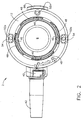
- FIG. 2 is a top view of the injection port of FIG. 1 .
- FIG. 3 is a bottom view of the injection port of FIG. 1 .
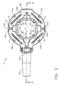
- FIG. 4 is a cross sectional view of the injection port of FIG. 1 taken along line 4-4 of FIG. 3 .
- FIG. 5 is an exploded perspective view of the injection port of FIG. 1 .
- FIG. 6 is perspective view of the bottom of the injection port of FIG. 1 , showing the attachment mechanism in the retracted position.
- FIG. 7 is a perspective view of the bottom of the injection port of FIG. 1 , similar to FIG. 6 , showing the attachment mechanism in the extended/fired position.
- FIG. 8 is a side cutaway view in partial cross-section illustrating a fastener of the attachment mechanism in the retracted position.
- FIG. 9 is a side cutaway view in partial cross-section similar to FIG. 8 illustrating a fastener of the attachment mechanism that is being advanced by the actuator ring toward the extended/fired position.
- FIG. 10 is a side cutaway view in partial cross-section similar to FIG. 8 illustrating a fastener of the attachment mechanism in the extended/fired position.
- FIG. 11 is a side cutaway view in partial cross-section similar to FIG. 8 illustrating a fastener of the attachment mechanism that is being advanced by the actuator ring toward the retracted position.
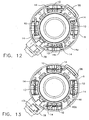
- FIG. 12 is a top view of the injection port of FIG. 1 , with the actuator ring omitted to illustrate the positions of the links when the fasteners are in the retracted position.
- FIG. 13 is a top view of the injection port of FIG. 1 , with the actuator ring omitted to illustrate the positions of the links when the fasteners are in the extended/fired position.
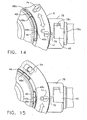
- FIG. 14 is an enlarged, fragmentary top view of the visual position indicator and actuator ring detent system of the attachment mechanism of FIG. 1 , in the retracted position.
- FIG. 15 is an enlarged, fragmentary top view of the visual position indicator and actuator ring detent system of the attachment mechanism of FIG. 1 in the extended/fired position.
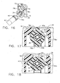
- FIG. 16 is an enlarged, fragmentary, exploded perspective view of the fitting and locking connector of the injection port of FIG. 1 .
- FIG. 17 is an enlarged, fragmentary partial cross-section view of the locking connector assembled to the fitting the septum retainer but not locked in place.
- FIG. 18 is an enlarged, fragmentary partial cross-section view similar to FIG. 17 showing the locking connector locked in place.
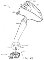
- FIG. 19 is an enlarged perspective view of the safety cap.
- FIG. 20 is a perspective view of an applier constructed to implant the injection port of FIG. 1 .
- FIG. 21 is a exploded, perspective view of the applier of FIG. 20 .
- FIG. 22 is a side view of the applier of FIG. 20 with one of the two body halves showing the internal components in the unapplied, non-actuated position.
- FIG. 23 is a side view of the applier of FIG. 20 similar to FIG. 22 , showing the internal components in the applied, actuated position.
- FIG. 24 is an enlarged, fragmentary side view of the linear to rotary cam mechanism of the applier of FIG 20 .
- FIG. 25 is an enlarged top perspective view of the locator of the applier of FIG. 20 .
- FIG. 26 is an enlarged bottom perspective view of the locator and the port actuator of the applier of FIG. 20 .
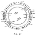
- FIG. 27 is a partially cut away end view of the locator of the applier of FIG. 20 .
- FIG. 28 is an enlarged, cross sectional view of the injection port of FIG. 1 retained by the locator of the applier of FIG. 20 .
- FIG. 29 is an enlarged, cross-sectional view of the injection port of FIG. 1 disposed in the locator of the applier of FIG. 20 after the applier has been actuated to rotate the applier actuator to the deployed position.
- FIGS. 1-5 there is shown an implantable injection port, generally indicated at 2, which embodies an attachment mechanism.
- Injection port 2 includes septum retainer 4, septum 6 and port body 8.
- Injection port 2, with the integrally constructed attachment mechanism, also includes one or more fasteners 10, actuator 12 and a plurality of link members 14.
- septum 6 which may be made of any biocompatible material such as silicone, is disposed partially within internal cavity 16 of septum retainer 4, adjacent annular flat 18.
- Septum retainer 4, port body 8, and actuator 12 may be made of any suitable biocompatible material having sufficient stiffness and strength, such as polyetheretherketon (known as PEEK).
- Fasteners 10 and link members 14 may be made of any suitable biocompatible material, such as stainless steel.
- Port body 8 includes annular rim 20, which engages the upper surface of septum 6 about an annular portion. Port body 8 is retained to septum retainer 4 by a plurality of pins 22 which are disposed through respective holes 24 formed in recesses 24a in port body 8 and which extend inwardly into respective recesses 26 formed about the bottom periphery of septum retainer 4. Pins 22 may be made of any suitable biocompatible material, such as stainless steel.
- the uncompressed height of septum 6 is approximately 5mm around the outer diameter and the uncompressed diameter is approximately 18mm.
- the exposed diameter for access to reservoir 20 is approximately 14mm.
- the distance between the lower surface of annular rim 20 and annular flat 18 is approximately 4mm, such that septum 6 is compressed approximately 20% to be adequately self healing to maintain a fluid tight system under pressure and still allow a low profile.
- Plate 28 is disposed in recess 16a formed in the bottom of septum retainer 4, underlying septum 6 and fluid chamber or reservoir 30. As seen in FIG. 4 , plate 28 does not contact sidewall 16b. In the embodiment depicted, plate 28 is metallic, such as stainless steel. When a needle is inserted through septum 6 to introduce or withdraw fluid from fluid chamber 30, such as in order to adjust the size of an adjustable gastric band, metallic plate 28 will protect septum retainer 4 from puncture and provide tactile feedback to the surgeon through the needle indicating that the needle has bottomed in reservoir 30. Plate 28 is held in place by retaining lip 4a extending over the periphery of plate 28 as best seen in FIGS 4 , 28 and 29 .
- retaining lip 4a extends upwardly as an annular lip, providing clearance for insertion of plate 28 into the recess at the bottom of septum retainer 4, and retaining lip 4a is then rolled or otherwise deformed to overlie at least a portion of the periphery of plate 28 thereby retaining plate 28.
- the diameter of recess 16a is smaller than the diameter of sidewall 16b, providing room to form the annular lip and to deform it into retaining lip 4a.
- Septum retainer 4 includes passageway 32, in fluid communication with fluid chamber 30, which is defined by fitting 34 extending from the periphery adjacent the bottom of retainer 4.
- Tube 36 which in the embodiment depicted, leads to an adjustable gastric band (not shown), is connected to fitting 34, being compressingly urged against annular rib 38 by connector 40, which is disposed about tube 36 and secured to port body 8 as described below.
- Sleeve 42 is disposed about tube 36, secured to connector 40 by annular ribs 44. Sleeve 42 relieves strain on tube 36, preventing tube 36 from kinking when loaded laterally.
- Actuator 12 is secured to port body 8. Although in the embodiment depicted actuator 12 is illustrated as an annular ring rotatably supported by port body 8, actuator 12 may be any suitable configuration and supported in any suitable manner to permit actuator 12 to function to move fasteners 10 between and including deployed and undeployed positions. As seen in FIG. 5 , port body 8 includes a plurality of downwardly and outwardly extending tabs 46. In the embodiment depicted, there are four equally spaced tabs 46. Actuator 12 includes an equal number of corresponding recesses 48, each having arcuate bottom 50.
- actuator 12 To assemble actuator 12 to port body 8, recesses 48 are aligned with tabs 46, and pushed down, temporarily deflecting tabs 46 inwardly until tabs 46 reach recesses 48 and move outwardly to dispose lower edges 46a in recesses 48 such that actuator is retained thereby.
- the lengths of tabs 46 and depth of recesses 48 allow some axial end play between actuator 12 and port body 8, as will be described below.
- Actuator 12 may rotate generally about the central axis of port body 8. In the embodiment depicted, actuator 12 may rotate through an angle of about 40 degrees, although any suitable angle may be used. In the embodiment depicted, when actuator 12 is rotated in the deploying direction, causing fasteners 10 to move to the deployed position, rotation of actuator 12 beyond the fully deployed position is limited by end 48c contacting tab 46.
- a detent system is formed by a pair of spaced apart raised detent ribs 48a, 48b extending inwardly from the wall of each recess 48, and a corresponding raised rib 46b extending outwardly from tab 46.
- the detent system assists in preventing actuator 12 from rotation and fasteners 10 from moving out of fully retracted or fully extended fired states under vibration or incidental loads, as described below.
- Actuator 12 includes a plurality of spaced apart openings or slots 54, which may be engaged by any suitable instrument to transmit the necessary torque to actuator 12 to extend fasteners 10 to the actuated position.
- Slots 54 are configured to be engaged by commercially available instruments, rectangular in the embodiment depicted, or by the dedicated applier described below.
- Port body 6 includes a plurality of recesses 56 disposed about its lower periphery which are configured to cooperate with the dedicated applier as described below.
- septum retainer 4 includes a plurality of locating tabs 58 extending outwardly from adjacent the bottom periphery of septum retainer 4. Locating tab 58a may be integral with fitting 34. Tabs 58 and 58a are located in respective complementarily shaped recesses 60 formed in the inner surface of port body 8, aligning septum retainer 4 properly with port body 8.
- FIG. 6 illustrates fasteners 10 in the retracted position. As can be seen, fasteners 10 are disposed in respective recesses or slots 60 formed in port body 8.
- FIG. 7 illustrates fasteners 10 in the extended, or fired, position, extending from slots 60. Rotation of actuator 12 moves fasteners 10 from the retracted position to the extended position.
- FIGS. 8-11 are a series of figures illustrating the operation of actuator 12 and one of the plurality of fasteners 10, it being understood that the operation on one of fasteners 10 may be the same as for all fasteners 10, which may, in one embodiment, be moved from a deployed position to an undeployed position simultaneously.
- FIG. 8 illustrates fastener 10 in a fully retracted state, the undeployed position, disposed completely within slot 62 such that sharp tip 64 is not exposed. This prevents tip 64 from accidentally sticking the surgeon or penetrating any object.
- Actuator 12 is illustrated rotated counter clockwise as far as permitted by recesses 48 and tabs 46. In this position, ribs 46b are disposed clockwise of ribs 48b, as seen in FIG. 14 .
- First ends 14a of link members 14 are rotatably carried by actuator 12, spaced apart at positions corresponding to the positions of fasteners 10. Second ends 14b are disposed within openings 66 of fasteners 10.
- integral actuator 12 is rotated in a deploying direction, which in one embodiment as depicted is clockwise (any suitable direction configured to actuate the attachment mechanism may be used), and rib 46b passes rib 48b, which may produce an audible signal in addition to a tactile signal to the surgeon.
- Second end 14b of link member 14 is free to move within slot 66 during actuation, as the force that rotates fastener 10 into the extended position is transmitted to fastener 10 through the interaction between cam surface 68 of fastener 10 and actuating cam surface 70 of actuator 12.
- actuator 12 rotates clockwise, actuating cam surface 70 engages and pushes against cam surface 68, rotating fastener 10 about pivot pin 22.
- fastener 10 is rotated about half way though its range of rotation, about 90 degrees as a result of the clockwise rotation of actuator 12.
- actuator cam surface 70 and cam surface 68 causes actuator 12 to move upward slightly as allowed by the tolerancing of the components.
- actuator cam surface 70 continues to engage and push against cam surface 68, rotating fastener 10 further counterclockwise.
- actuator 12 is rotated clockwise to its fullest extent, with rib 46b having been urged past detent rib 48a (see FIG. 15 ).
- fastener 10 has rotated to its fullest extent, almost 180 degrees in the embodiment illustrated, with tip 64 disposed within recess 62.
- actuator cam surface 70 is over center, and actuator 12 is resistant to being back driven by an undeploying force imparted to fastener 10 as cam surface 68 acts against actuator cam surface 70 in a direction that tends to push actuator 12 up instead of rotating actuator 12.
- the distal end portion of fastener 10 is configured essentially as a beam, depicted as having a generally rectangular cross section along its length, tapering to sharp tip 64.
- pin 22 is illustrated as being a separate piece from fastener 10, the two may be integral or even of unitary construction.
- actuator 12 may be rotated in an undeploying direction, counterclockwise in one embodiment depicted. Starting with the position of actuator 12 shown in FIG. 10 , actuator 12 may be rotated counterclockwise, with actuator cam surface 70 sliding against cam surface 68, without rotating fastener 10. In the embodiment depicted, continued counterclockwise rotation of actuator 12 moves cam surface 70 out of contact with cam surface 68, with no substantial rotating force being exerted on fastener 10 until second end 14b of link member reaches a location in slot 66, such as at one end of slot 66, at which link member 14 begins pulling against slot 66 causing fastener 10 to rotate and begin to retract.
- actuator 12 has been advanced counterclockwise compared to the position shown in FIG. 10 , and fastener 10 is rotated approximately halfway through its range.
- actuator 12 is in different positions with fastener 10 in the same position, in dependence upon whether the attachment mechanism is being actuated or deactuated (retracted). This results from the lost motion that results when link member 14 is pulling on slot 66 in comparison to actuator cam surface 70 pushing directly on cam surface 68.
- actuator 12 is rotated until detent rib 46b snaps past detent rib 48b.
- tip 64 may be disposed fully in slot or recess 62. Further undeploying rotation of actuator 12 is prevented by link member 14 which is prevented from further movement by fastener 10.
- actuator 12 includes openings 52a formed therethrough, which align with corresponding openings 52b formed in port body 8 when actuator is in the undeployed position. Openings 52a and 52b may be used by the surgeon to suture injection port 2 if the integral attachment mechanism is not used.
- Link members 14 are shown in their actual positions when first ends 14a are supported by actuator 12, in the deployed and in the undeployed states.
- FIGS. 14 and 15 there is illustrated a top view of the visual position indicator and a portion of the actuator ring detent system of the attachment mechanism as embodied in injection port 2.
- the attachment mechanism is in the retracted, undeployed state or position.
- detent rib 46b is clockwise of detent rib 48b, and thus in the undeployed detent position.
- the attachment mechanism is in the actuated or deployed position. In this position, detent rib 46b is counterclockwise of detent rib 48b, and thus in the deployed detent position.
- FIGS. 14 and 15 illustrate a visual indicator of the state of the attachment mechanism.
- indicia may be utilized, such as an unlocked lock icon 72 and a locked lock icon 74 molded integral with actuator ring 12. Any suitable graphic indicator may be used, and may be printed on or otherwise applied in a suitable manner.
- Port body 6 may include indicator 76 to provide a reference point for the movable indicia.
- Arrow 78 may be included to indicate the bidirectional motion of actuator 12.
- FIGS. 16-18 illustrate the locking connection between connector 40 and port body 6.
- FIG. 16 is an exploded perspective view showing fitting 34 partially surrounded by extension 78.
- FIG. 17 shows extension 78 in cross-section, with connector 40 generally disposed about fitting 34 and tube 36 aligned in circumferential slot 78c of extension 78.
- Connector 40 includes a pair of tabs 40a, 40b, extending outwardly therefrom.
- To assemble, connector 40 is guided along tube 36 and fitting 34, with tabs 40a and 40b aligned with openings 78a and 78b of extension 78. With tabs 40a and 40b aligned with circumferential slot 78c, connector 40 is rotated to lock it in place.
- detent edge 78d creates interference opposing the rotation of tab 40a, but is dimensioned to allow tab 40a to be rotated past, to the locked position seen in FIG. 18 .
- FIG. 19 illustrates safety cap 80 which may be removably secured to the bottom of injection port 2 to cover fasteners 10 to protect users from accidental exposure to sharp tips 64 while handling injection port 2.
- Safety cap 80 includes body 82 with annular rim 84 and raised center 86 defining annular recess 88. Safety cap 80 may be oriented and retained to injection port through any suitable configuration.
- body 82 includes a plurality of arcuate retention tabs 90 extending upwardly from raised center 86.
- Arcuate retention tabs 90 are shaped complementarily to corresponding arcuate slots 92, best seen in FIGS. 3 , 6 and 7 , and may have ribs as shown.
- Safety cap 80 is secured to injection port 2 by inserting arcuate retention tabs 90 into arcuate slots 92, which are sized to retain tabs 90. Fasteners 10 are thus aligned with annular recess 88, which is sized to allow fasteners 10 to be extended without contacting safety cap 80. As depicted, since arcuate retention tabs 90 and arcuate slots 92 are respectively the same size and equally spaced, safety cap 80 is not indexed to a particular position, and may be secured to injection port 2 in four different positions. Safety cap 80 includes pull tab 94 with raised a plurality of ribs 96 to provide a better gripping surface. Although pull tab 94 may be oriented in any suitable orientation, in the embodiment, the relative position between pull tab 94 and arcuate retention tabs 90 locates pull tab at 45 degrees to the direction of connector 40. Tabs 90 and slots 92 may be of any suitable shape.
- FIG. 20 illustrates applier, generally indicated at 100, which is configured to position, actuate, deactuate, remove or reposition injection port 2.
- applier 100 includes body 102, locator 104, actuator 106 and safety switch 108.
- injection port 2 may be assembled to locator 104, with extension 78 and tab 96 disposed in alignment slots 110 and 112.
- Locator 104 is angled relative to body 102, allowing for easier and better visualization of injection port 2 during implantation. In the embodiment depicted, the angle is 20 degrees and the shaft portion of body 102 is 10 cm.
- body 102 includes first and second halves 102a and 102b assembled to each other to contain the internal components. Except for locating pins 202, pivot pins 114 and ship laps, body halves 102a and 102b are substantially similar to each other. Locating pins 202, illustrated as extending from body half 102a, fit into respective complementarily shaped openings (not illustrated) on body half 102b. The engagement of the plurality of locating pins 202 in the openings is sufficient to hold body halves 102a and 102b together. Pins 202 may alternatively extend from body half 102b with the openings carried by body half 102a. Any suitable configuration may be used to assemble and secure body halves 102a and 102b together.
- Actuator 106 includes first and second halves 106a and 106b. Locating pins 204, illustrated as extending from actuator half 106a, fit into respective complementarily shaped openings (not illustrated) on actuator half 106b. Pins 204 may alternatively extend from actuator half 106b with the openings carried by actuator half 106a. Any suitable configuration may be used to assemble and secure actuator halves 106a and 106b together.
- Body half 102b includes pivot pin 114b which rotatably supports actuator 106 at one end, extending through pivot holes 116a and 116b into opening 114a.
- Body half 102a includes pivot pin 118b (see FIG. 22 ) which rotatably supports safety switch 108.
- Body halves 102a and 102b, locator 104, actuator halves 106a and 106b, and safety switch 108 may be made of any biocompatible material such as polycarbonate.
- applier 100 includes cam 120, drive shaft 122 with flexible shaft 124, drive shaft pin 126, cam return spring 128, safety biasing spring 130, and actuator 132.
- Actuator 132 is configured to effect the deployment or undeployment of the attachment mechanism of the medical implant.
- Cam 120 includes shaft 134 and cam collar 136.
- the upper end of shaft 134 has a "T" configuration terminating in cross member 138.
- Cam collar 136 defines a hollow interior and a pair of spaced apart, complementarily shaped cam tracks 140a and 140b formed on opposite sides of cam collar 136.
- Upper end 122a of drive shaft 122 is disposed partially within the hollow interior defined by cam collar 136, captured therein by drive shaft pin 126.
- Drive shaft pin 126 is sized such that each end is located within a respective cam track 140a, 140b.
- the length of the hollow interior allows upper end 122a to reciprocate therein, with cam tracks 140a and 140b imparting rotation to drive shaft 122 through drive shaft pin 126 during reciprocation.
- Cam 120, drive shaft 122 and actuator 132 may be made of any suitable material having sufficient stiffness and strength.
- cam 120 and actuator 132 are made of a liquid crystal polymer such as Vectra tm LCP, and drive shaft 122 is made of a PPE+PS such as Noryl tm .
- Drive shaft pin 126 and cam return spring 128 may be made of any suitable material, such as stainless steel.
- Cam 120 is retained between body portions 102a and 102b, and in one embodiment, such as that depicted can reciprocate.
- Cam collar 136 has spaced apart, generally flat outer surfaces 142a and 142b tracks through which 140a and 140b are formed. These surfaces 140a and 140b are disposed between guide walls 144a and 144b formed in body portions 102a and 102b.
- Cam collar 136 also includes oppositely facing channels 146a and 146b (see FIG. 23 ), which are guided for axial reciprocation by guides 148a and 148b (not illustrated) formed in body portions 102a and 102b, respectively.
- the upper end of shaft 134 and cross member 138 are disposed sandwiched between actuator halves 106a and 106b.
- Each actuator half 106a, 106b includes a cam track 150 defined by a pair of spaced apart walls 150a and 150b extending from the interior surfaces of actuator halves 106a and 106b.
- Cam track 150 is configured to receive and guide cross member 138 as actuator 106 is rotated about pin 114, forcing cam 120 to advance linearly downwardly into body 102.
- Drive shaft 122 includes annular collar 152 which is received in slots 154a and 154b (not illustrated) formed in body halves 102a and 102b, respectively. Slots 154a and 154b rotatably support drive shaft 122.
- Drive shaft 122 and cam 120 are generally aligned and collinear with each other, defining the axis of the shaft portion of body 102. As cam 120 is advanced downwardly, drive shaft pin 126 follows cam tracks 140a and 140b, causing drive shaft 122 to rotate, thus converting linear motion to rotary motion.
- Cam return spring 128 provides a nominal return force against cam collar 136.
- Flexible shaft 124 is supported by a plurality of ribs 156, formed in each body half 102a, 102b, which support the bend in flexible shaft 124 that permits the rotary motion to be transferred to actuator 132 which is disposed at an angle relative to the shaft of body 102.
- Flexible shaft 124 may be made of any suitable biocompatible material, such as stainless steel.
- flexible shaft 124 has a stranded construction, with a center core having multiple layers of wire wrapped thereabout. Ends 124a and 124b of flexible shaft 124 may be attached to end 122b and actuator 132, respectively, in any suitable manner which sufficiently limits rotational end play to prevent or minimize lost rotational motion.
- end 124a was overmolded into end 122b, and end 124b was press fit into actuator 132.
- end 124a could be press fit into end 122b, and end 124b overmolded into actuator 132, both could be press fit, or both could be overmolded (with a corresponding change to the configuration of locator 104 to allow assembly.
- actuator 132 includes disc shaped member 158 and shaft 160 extending upwardly therefrom.
- the upper end of shaft 160 includes a pair of outwardly extending tabs 162a and 162b.
- Locator 104 includes hub 164 defining bore 166 therethrough.
- Bore 166 is shaped to receive and rotatably support shaft 160, and includes two outwardly extending arcuate recesses 168a and 168b configured to provide assembly clearance for tabs 162a and 162b, allowing hub 164 to be inserted into bore 166.
- shaft 160 and hub 164 are sized such that tabs 162a and 162b are located above upper surface 164a of hub 164, allowing rotation of actuator 132 while retaining it axially relative to hub 164. Stops 170 and 170b extend upwardly from upper surface 164a, limiting the rotation of actuator 132.
- Bore 166 defines a central axis of locator 104 about which actuator 132 is rotated. The central axis of locator 104 is disposed at an angle to the axis of the shaft portion of body 102, as previously mentioned.
- Hub 164 includes a pair of oppositely extending tabs 172a and 172b which retain port actuator 104 to body 102 and prevent rotation.
- Body halves 102a and 102b include respective recesses 174a (see FIG. 21 ) and 174b (not illustrated) shaped complementarily to tabs 172a and 172b.
- Actuator 132 includes a pair of spaced apart posts 176a and 176b, extending from adjacent periphery 158a of member 158.
- Posts 176a and 176b are shaped complementarily with openings 54.
- the distal ends of posts 176a and 167b are tapered to assist in guiding posts 176a and 176b into openings 54.
- Any suitable configuration may be utilized to create releasable contact between actuator 132 and actuator 12 capable of actuating actuator 12.
- Disc shaped member 158 also includes a pair of spaced apart cams 178a and 178b which extend outwardly and upwardly from periphery 158a of member 158.
- FIG. 27 illustrates cam 178a at a cross-section taken near the bottom surface of member 158.
- Cams 178a and 178b include ramps 180a and 180b which start at periphery 158a and lead out to surfaces 182a and 182b, respectively.
- Each surface 182a, 182b is arcuate, shown in the embodiment depicted as generally having a constant radius.
- locator 104 includes a pair of spaced apart cantilever arms 184a and 184b, each having rib 186a and 186b, respectively.
- FIG. 27 illustrates arm 184a in cross-section taken through rib 186a, at the same level as for cam 178a.
- arms 184a and 184b include respective inwardly extending flanges 188a and 188b.
- Flanges 188a and 188b are shaped complementarily to recesses 56 on port body 6, configured to engage ledges 56a when injection port 2 is retained by locator 104.
- posts 176a and 176b are generally aligned with arms 184a and 184b, respectively, although posts 176a and 176b may be at any position that corresponds to position of the actuating feature of actuator 12, which in the embodiment depicted is openings 54.
- actuator 132 rotates (counterclockwise in the embodiment depicted when viewed from the bottom), advancing cams 178a and 178b such that ramps 180a and 180b contact ribs 186a and 186b, respectively, deflecting arms 184a and 184b outwardly.
- arms 184a and 184b are deflected a distance sufficient to move flanges 188a and 188b to a position where they no longer extend into recesses 56 or contact ledges 56a, thus releasing injection port 2 from locator 104.
- FIG. 28 illustrates injection port 2 disposed in and retained by locator 104, with extension housing 78 and tab 96 disposed in slots 110 and 112, respectively (see FIG. 20 , not seen in FIG 28 ).
- posts 176a and 176b extend into openings 54 of actuator 12, and flanges 188a and 188b extending into recesses 56 proximal ledges 56a.
- Safety cap 80 is connected to injection port 12 when injection port 12 is inserted into locator 104, covering fasteners 10 (not seen in FIG 28 ).
- actuator 106 is oriented in the undeployed position so that actuator 132 is in the undeployed position.
- Actuator 12 is oriented in the undeployed position, and inserted into locator 104, with extension housing 78 and tab 96 disposed in slots 110 and 112, respectively.
- Actuator 106 may, as illustrated in FIG. 20 , include a visual indicator to indicate whether actuator 106 is fully in the undeployed state, such as unlocked lock icon 190, and indicia to indicate whether actuator 106 is in the deployed state, such as locked lock icon 192.
- a visual indicator to indicate whether actuator 106 is fully in the undeployed state, such as unlocked lock icon 190, and indicia to indicate whether actuator 106 is in the deployed state, such as locked lock icon 192.
- Such visual indication may be include by any suitable manner, such as by molding integral with actuator 106, applying as a adhesive film or such, or printing directly on actuator 106. With the indicator illustrated, unlocked lock icon 190 is visible adjacent the upper edge of body 102, although other configurations of indication may be utilized, such as a window or such formed in body 102 to reveal the indicia.
- locator 104 and a portion of 102 is inserted through an incision by the surgeon and located in the desired position adjacent the body tissue to which the medical implant (which in the embodiment depicted is an injection port 2) is to be attached.
- the angle between locator 104 and body 102 allows the surgeon to visualize the site directly.
- the one or more fasteners 10 With injection port 2 in position, the one or more fasteners 10 are moved from the undeployed position to the deployed position in an annular path to engage the tissue.
- Fasteners 10 allow injection port 2 to be secured to the tissue with a retention strength equal to or greater than when secured with sutures.
- Safety switch 108 is rotated about pivot pin 118, withdrawing lockout tab 194 from lower opening 196, allowing actuator 106 to be rotated about pivot pin 114. This action causes cam track 150 to move cross member 138 downward, causing cam collar 136 to rotate drive shaft 122, thereby rotating actuator 132 relative to locator 104.
- actuator 132 actuates actuator 12 by rotating it.
- lockout tab 194 is urged into upper opening 198, retaining actuator 106 in the deployed position.
- spring 130 biases lockout tab 194 sufficiently to produce sound as lockout tab 194 snaps into upper opening 198, providing an audible signal that actuator 106, and therefore actuator 12 and fasteners 10 are deployed fully.
- actuator 12 has been rotated and fasteners 10 are in the deployed position having penetrated the body tissue, such as the rectus sheath.
- Cams 178a and 178b have been rotated to a position where surfaces 182a and 182b are adjacent ribs 186a and 186b, with arms 184a and 184b deflected outwardly such that flanges 188a and 188b are not disposed in recesses 56 and not engaging ledges 56a.
- the surgeon may withdraw locator 104, leaving injection port 2 in place. If a visual indicator of the state of the attachment mechanism is included with the implant, the surgeon can tell whether the attachment mechanism is fully deployed.
- the attachment mechanism embodied in injection port 2 is configured to be reversible so that the medical implant, injection port 2, may be moved, such as to reposition it or remove it from the patient.
- locator 104 is placed over injection port 2, locating extension 78 and tab 96 in slots 110 and 112 so that posts 176a and 176b are engaged with recesses 54.
- Safety switch 108 is rotated to withdraw lockout tab 194 from upper opening 198, while the surgeon pulls up on extension 200 of actuator 106.
- cam return spring 128 urges cam collar 136 upwardly, extension 200 allows an additional return force to be applied.
- actuator 132 rotates actuator 12, moving fasteners 10 from the deployed position to the undeployed position simultaneously, while cams 178a and 178b disengage from ribs 186a and 186b, allowing flanges 188a and 188b to engage recess 56 and ledge 56a so as to retain injection port 2 in locator 104.
- lockout tab 194 snaps into lower opening 196, generating an audible signal that actuator 106 is undeployed fully, and injection port 2 is detached from the body tissue and may be relocated or removed.
Abstract
Description
- The present invention relates generally to surgically implantable injection ports.
- Implantable medical devices are typically implanted in a patient to perform a therapeutic function for that patient. Non-limiting examples of such devices include pace makers, vascular access ports, injection ports (such as used with gastric bands) and gastric pacing devices. Such implants need to be attached, typically subcutaneously, in an appropriate place in order to function properly. An implantable port device is described in German patent application
DE-42 11 045 , according to which a port comprises a housing having a bottom face and sidewalls supporting an elastic membrane and enclosing a reservoir. A spring-biased catheter line closure member is provided inside the reservoir such that an opening and closing of the catheter line is effected upon insertion and retraction of an injector needle through the membrane. A further configuration for an injection port is known fromU.S. patent 4781680 , and includes a septum member extending about the top and sides of the device and enclosing an annular member defining a reservoir and provided radially inwardly of a plurality of base members which are surrounded circumferentially by the sidewalls of said septum material. - According to the present invention, there is provided a surgically implantable injection port as defined in appended
claim 1. Further preferred embodiments thereof are defined insubclaims 2 and 3. The present disclosure also encompasses an attachment mechanism to secure an medical implant device to body tissue quickly and easily. The attachment mechanism may be reversible, allowing the implantable medical device to be detached quickly and easily for repositioning or removal. Although standard, commercially available instruments may be used to actuate the attachment mechanism, the present disclosure also encompasses an applier for locating an implantable medical device in the desired location and quickly and easily actuating the attachment mechanism to secure the implantable medical device. - The accompanying drawings, which are incorporated in and constitute a part of this specification, illustrate embodiments of the invention, and, together with the general description of the invention given above, and the detailed description of the embodiments given below, serve to explain the principles of the present invention.
-
FIG. 1 is a perspective view of an injection port with an attachment mechanism constructed in accordance with the present invention. -
FIG. 2 is a top view of the injection port ofFIG. 1 . -
FIG. 3 is a bottom view of the injection port ofFIG. 1 . -
FIG. 4 is a cross sectional view of the injection port ofFIG. 1 taken along line 4-4 ofFIG. 3 . -
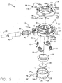
FIG. 5 is an exploded perspective view of the injection port ofFIG. 1 . -
FIG. 6 is perspective view of the bottom of the injection port ofFIG. 1 , showing the attachment mechanism in the retracted position. -
FIG. 7 is a perspective view of the bottom of the injection port ofFIG. 1 , similar toFIG. 6 , showing the attachment mechanism in the extended/fired position. -
FIG. 8 is a side cutaway view in partial cross-section illustrating a fastener of the attachment mechanism in the retracted position. -
FIG. 9 is a side cutaway view in partial cross-section similar toFIG. 8 illustrating a fastener of the attachment mechanism that is being advanced by the actuator ring toward the extended/fired position. -
FIG. 10 is a side cutaway view in partial cross-section similar toFIG. 8 illustrating a fastener of the attachment mechanism in the extended/fired position. -
FIG. 11 is a side cutaway view in partial cross-section similar toFIG. 8 illustrating a fastener of the attachment mechanism that is being advanced by the actuator ring toward the retracted position. -
FIG. 12 is a top view of the injection port ofFIG. 1 , with the actuator ring omitted to illustrate the positions of the links when the fasteners are in the retracted position. -
FIG. 13 is a top view of the injection port ofFIG. 1 , with the actuator ring omitted to illustrate the positions of the links when the fasteners are in the extended/fired position. -
FIG. 14 is an enlarged, fragmentary top view of the visual position indicator and actuator ring detent system of the attachment mechanism ofFIG. 1 , in the retracted position. -
FIG. 15 is an enlarged, fragmentary top view of the visual position indicator and actuator ring detent system of the attachment mechanism ofFIG. 1 in the extended/fired position. -
FIG. 16 is an enlarged, fragmentary, exploded perspective view of the fitting and locking connector of the injection port ofFIG. 1 . -
FIG. 17 is an enlarged, fragmentary partial cross-section view of the locking connector assembled to the fitting the septum retainer but not locked in place. -
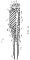
FIG. 18 is an enlarged, fragmentary partial cross-section view similar toFIG. 17 showing the locking connector locked in place. -
FIG. 19 is an enlarged perspective view of the safety cap. -
FIG. 20 is a perspective view of an applier constructed to implant the injection port ofFIG. 1 . -
FIG. 21 is a exploded, perspective view of the applier ofFIG. 20 . -
FIG. 22 is a side view of the applier ofFIG. 20 with one of the two body halves showing the internal components in the unapplied, non-actuated position. -
FIG. 23 is a side view of the applier ofFIG. 20 similar toFIG. 22 , showing the internal components in the applied, actuated position. -
FIG. 24 is an enlarged, fragmentary side view of the linear to rotary cam mechanism of the applier ofFIG 20 . -
FIG. 25 is an enlarged top perspective view of the locator of the applier ofFIG. 20 . -
FIG. 26 is an enlarged bottom perspective view of the locator and the port actuator of the applier ofFIG. 20 . -
FIG. 27 is a partially cut away end view of the locator of the applier ofFIG. 20 . -
FIG. 28 is an enlarged, cross sectional view of the injection port ofFIG. 1 retained by the locator of the applier ofFIG. 20 . -
FIG. 29 is an enlarged, cross-sectional view of the injection port ofFIG. 1 disposed in the locator of the applier ofFIG. 20 after the applier has been actuated to rotate the applier actuator to the deployed position. - Reference will now be made in detail to the present preferred embodiment of the invention, an example of which is illustrated in the accompanying drawings.
- In the following description, like reference characters designate like or corresponding parts throughout the several views. Also, in the following description, it is to be understood that terms such as front, back, inside, outside, and the like are words of convenience and are not to be construed as limiting terms. Terminology used in this patent is not meant to be limiting insofar as devices described herein, or portions thereof, may be attached or utilized in other orientations. Referring in more detail to the drawings, an embodiment of the invention will now be described.
- Referring to
FIGS. 1-5 , there is shown an implantable injection port, generally indicated at 2, which embodies an attachment mechanism. -
Injection port 2 includesseptum retainer 4,septum 6 andport body 8.Injection port 2, with the integrally constructed attachment mechanism, also includes one ormore fasteners 10,actuator 12 and a plurality oflink members 14. - As seen in
FIG. 4 ,septum 6, which may be made of any biocompatible material such as silicone, is disposed partially withininternal cavity 16 ofseptum retainer 4, adjacentannular flat 18.Septum retainer 4,port body 8, andactuator 12 may be made of any suitable biocompatible material having sufficient stiffness and strength, such as polyetheretherketon (known as PEEK).Fasteners 10 andlink members 14 may be made of any suitable biocompatible material, such as stainless steel. -
Port body 8 includesannular rim 20, which engages the upper surface ofseptum 6 about an annular portion.Port body 8 is retained toseptum retainer 4 by a plurality ofpins 22 which are disposed throughrespective holes 24 formed inrecesses 24a inport body 8 and which extend inwardly intorespective recesses 26 formed about the bottom periphery ofseptum retainer 4.Pins 22 may be made of any suitable biocompatible material, such as stainless steel. - The uncompressed height of
septum 6 is approximately 5mm around the outer diameter and the uncompressed diameter is approximately 18mm. The exposed diameter for access toreservoir 20 is approximately 14mm. The distance between the lower surface ofannular rim 20 andannular flat 18 is approximately 4mm, such thatseptum 6 is compressed approximately 20% to be adequately self healing to maintain a fluid tight system under pressure and still allow a low profile. -
Plate 28 is disposed inrecess 16a formed in the bottom ofseptum retainer 4, underlyingseptum 6 and fluid chamber orreservoir 30. As seen inFIG. 4 ,plate 28 does not contactsidewall 16b. In the embodiment depicted,plate 28 is metallic, such as stainless steel. When a needle is inserted throughseptum 6 to introduce or withdraw fluid fromfluid chamber 30, such as in order to adjust the size of an adjustable gastric band,metallic plate 28 will protectseptum retainer 4 from puncture and provide tactile feedback to the surgeon through the needle indicating that the needle has bottomed inreservoir 30.Plate 28 is held in place by retaininglip 4a extending over the periphery ofplate 28 as best seen inFIGS 4 ,28 and29 . Initially, retaininglip 4a extends upwardly as an annular lip, providing clearance for insertion ofplate 28 into the recess at the bottom ofseptum retainer 4, and retaininglip 4a is then rolled or otherwise deformed to overlie at least a portion of the periphery ofplate 28 thereby retainingplate 28. In the embodiment depicted the diameter ofrecess 16a is smaller than the diameter ofsidewall 16b, providing room to form the annular lip and to deform it into retaininglip 4a. -
Septum retainer 4 includespassageway 32, in fluid communication withfluid chamber 30, which is defined by fitting 34 extending from the periphery adjacent the bottom ofretainer 4.Tube 36, which in the embodiment depicted, leads to an adjustable gastric band (not shown), is connected to fitting 34, being compressingly urged againstannular rib 38 byconnector 40, which is disposed abouttube 36 and secured to portbody 8 as described below.Sleeve 42 is disposed abouttube 36, secured toconnector 40 byannular ribs 44.Sleeve 42 relieves strain ontube 36, preventingtube 36 from kinking when loaded laterally. -
Actuator 12 is secured toport body 8. Although in the embodiment depictedactuator 12 is illustrated as an annular ring rotatably supported byport body 8,actuator 12 may be any suitable configuration and supported in any suitable manner to permitactuator 12 to function to movefasteners 10 between and including deployed and undeployed positions. As seen inFIG. 5 ,port body 8 includes a plurality of downwardly and outwardly extendingtabs 46. In the embodiment depicted, there are four equally spacedtabs 46.Actuator 12 includes an equal number ofcorresponding recesses 48, each having arcuate bottom 50. To assembleactuator 12 toport body 8, recesses 48 are aligned withtabs 46, and pushed down, temporarily deflectingtabs 46 inwardly untiltabs 46 reach recesses 48 and move outwardly to disposelower edges 46a inrecesses 48 such that actuator is retained thereby. The lengths oftabs 46 and depth ofrecesses 48 allow some axial end play betweenactuator 12 andport body 8, as will be described below. -
Actuator 12 may rotate generally about the central axis ofport body 8. In the embodiment depicted,actuator 12 may rotate through an angle of about 40 degrees, although any suitable angle may be used. In the embodiment depicted, whenactuator 12 is rotated in the deploying direction, causingfasteners 10 to move to the deployed position, rotation ofactuator 12 beyond the fully deployed position is limited byend 48c contacting tab 46. - A detent system is formed by a pair of spaced apart raised
detent ribs 48a, 48b extending inwardly from the wall of eachrecess 48, and a corresponding raisedrib 46b extending outwardly fromtab 46. The detent system assists in preventingactuator 12 from rotation andfasteners 10 from moving out of fully retracted or fully extended fired states under vibration or incidental loads, as described below. -
Actuator 12 includes a plurality of spaced apart openings orslots 54, which may be engaged by any suitable instrument to transmit the necessary torque toactuator 12 to extendfasteners 10 to the actuated position.Slots 54 are configured to be engaged by commercially available instruments, rectangular in the embodiment depicted, or by the dedicated applier described below.Port body 6 includes a plurality ofrecesses 56 disposed about its lower periphery which are configured to cooperate with the dedicated applier as described below. - Referring also to
FIGS. 6 and 7 ,septum retainer 4 includes a plurality of locatingtabs 58 extending outwardly from adjacent the bottom periphery ofseptum retainer 4. Locatingtab 58a may be integral withfitting 34.Tabs recesses 60 formed in the inner surface ofport body 8, aligningseptum retainer 4 properly withport body 8. -
FIG. 6 illustratesfasteners 10 in the retracted position. As can be seen,fasteners 10 are disposed in respective recesses orslots 60 formed inport body 8.FIG. 7 illustratesfasteners 10 in the extended, or fired, position, extending fromslots 60. Rotation ofactuator 12moves fasteners 10 from the retracted position to the extended position. -
FIGS. 8-11 are a series of figures illustrating the operation ofactuator 12 and one of the plurality offasteners 10, it being understood that the operation on one offasteners 10 may be the same as for allfasteners 10, which may, in one embodiment, be moved from a deployed position to an undeployed position simultaneously.FIG. 8 illustratesfastener 10 in a fully retracted state, the undeployed position, disposed completely withinslot 62 such thatsharp tip 64 is not exposed. This preventstip 64 from accidentally sticking the surgeon or penetrating any object.Actuator 12 is illustrated rotated counter clockwise as far as permitted byrecesses 48 andtabs 46. In this position,ribs 46b are disposed clockwise ofribs 48b, as seen inFIG. 14 . First ends 14a oflink members 14 are rotatably carried byactuator 12, spaced apart at positions corresponding to the positions offasteners 10. Second ends 14b are disposed withinopenings 66 offasteners 10. - To actuate the attachment mechanism,
integral actuator 12 is rotated in a deploying direction, which in one embodiment as depicted is clockwise (any suitable direction configured to actuate the attachment mechanism may be used), andrib 46b passesrib 48b, which may produce an audible signal in addition to a tactile signal to the surgeon.Second end 14b oflink member 14 is free to move withinslot 66 during actuation, as the force that rotatesfastener 10 into the extended position is transmitted tofastener 10 through the interaction betweencam surface 68 offastener 10 andactuating cam surface 70 ofactuator 12. Asactuator 12 rotates clockwise, actuatingcam surface 70 engages and pushes againstcam surface 68, rotatingfastener 10 aboutpivot pin 22. The majority of the force from actuatingcam surface 70 acts tangentially oncam surface 68, off center relative to pivotpin 22, causingfastener 10 to rotate. During actuation,end 14b oflink member 14 remains free to move withinslot 66, applying no driving force to rotatefastener 10. - In
FIG. 9 ,fastener 10 is rotated about half way though its range of rotation, about 90 degrees as a result of the clockwise rotation ofactuator 12. Asactuator 12 is rotated clockwise, the force betweenactuator cam surface 70 andcam surface 68 causes actuator 12 to move upward slightly as allowed by the tolerancing of the components. Asactuator 12 is rotated further clockwise from the position shown inFIG. 9 ,actuator cam surface 70 continues to engage and push againstcam surface 68, rotatingfastener 10 further counterclockwise. - In
FIG. 10 ,actuator 12 is rotated clockwise to its fullest extent, withrib 46b having been urged past detent rib 48a (seeFIG. 15 ). In this position,fastener 10 has rotated to its fullest extent, almost 180 degrees in the embodiment illustrated, withtip 64 disposed withinrecess 62. In this position,actuator cam surface 70 is over center, andactuator 12 is resistant to being back driven by an undeploying force imparted tofastener 10 as cam surface 68 acts againstactuator cam surface 70 in a direction that tends to pushactuator 12 up instead of rotatingactuator 12. The distal end portion offastener 10 is configured essentially as a beam, depicted as having a generally rectangular cross section along its length, tapering tosharp tip 64. Withfastener 10 extending approximately 180 degrees in the fully extended state, the deployed position, forces which might act onfasteners 10 tend to act through the pivot axis defined bypivot pin 22, instead of rotatingfasteners 10. It is noted that althoughpin 22 is illustrated as being a separate piece fromfastener 10, the two may be integral or even of unitary construction. - If it is desirable to retract
fasteners 10, such as to remove or reposition the implanted device,actuator 12 may be rotated in an undeploying direction, counterclockwise in one embodiment depicted. Starting with the position ofactuator 12 shown inFIG. 10 ,actuator 12 may be rotated counterclockwise, withactuator cam surface 70 sliding againstcam surface 68, without rotatingfastener 10. In the embodiment depicted, continued counterclockwise rotation ofactuator 12moves cam surface 70 out of contact withcam surface 68, with no substantial rotating force being exerted onfastener 10 untilsecond end 14b of link member reaches a location inslot 66, such as at one end ofslot 66, at which linkmember 14 begins pulling againstslot 66 causingfastener 10 to rotate and begin to retract. - As seen in
FIG. 11 ,actuator 12 has been advanced counterclockwise compared to the position shown inFIG. 10 , andfastener 10 is rotated approximately halfway through its range. As can be seen by comparingFIG. 9 to FIG. 11 ,actuator 12 is in different positions withfastener 10 in the same position, in dependence upon whether the attachment mechanism is being actuated or deactuated (retracted). This results from the lost motion that results whenlink member 14 is pulling onslot 66 in comparison toactuator cam surface 70 pushing directly oncam surface 68. To retractfasteners 10 fully,actuator 12 is rotated untildetent rib 46b snapspast detent rib 48b. - Referring to
FIG. 8 , whenfasteners 10 reach the fullyundeployed position tip 64 may be disposed fully in slot orrecess 62. Further undeploying rotation ofactuator 12 is prevented bylink member 14 which is prevented from further movement byfastener 10. - Referring to
FIGS. 2 and3 ,actuator 12 includesopenings 52a formed therethrough, which align withcorresponding openings 52b formed inport body 8 when actuator is in the undeployed position.Openings injection port 2 if the integral attachment mechanism is not used. - Referring to
FIGS. 12 and 13 , the attachment mechanism is shown withoutactuator 12.Link members 14 are shown in their actual positions when first ends 14a are supported byactuator 12, in the deployed and in the undeployed states. - Referring to
FIGS. 14 and 15 , there is illustrated a top view of the visual position indicator and a portion of the actuator ring detent system of the attachment mechanism as embodied ininjection port 2. InFIG. 14 , the attachment mechanism is in the retracted, undeployed state or position. In this position,detent rib 46b is clockwise ofdetent rib 48b, and thus in the undeployed detent position. InFIG. 15 , the attachment mechanism is in the actuated or deployed position. In this position,detent rib 46b is counterclockwise ofdetent rib 48b, and thus in the deployed detent position. -
FIGS. 14 and 15 illustrate a visual indicator of the state of the attachment mechanism. As seen inFIG. 14 , indicia may be utilized, such as anunlocked lock icon 72 and a lockedlock icon 74 molded integral withactuator ring 12. Any suitable graphic indicator may be used, and may be printed on or otherwise applied in a suitable manner.Port body 6 may includeindicator 76 to provide a reference point for the movable indicia.Arrow 78 may be included to indicate the bidirectional motion ofactuator 12. -
FIGS. 16-18 illustrate the locking connection betweenconnector 40 andport body 6.FIG. 16 is an exploded perspective view showing fitting 34 partially surrounded byextension 78.FIG. 17 shows extension 78 in cross-section, withconnector 40 generally disposed about fitting 34 andtube 36 aligned incircumferential slot 78c ofextension 78.Connector 40 includes a pair oftabs 40a, 40b, extending outwardly therefrom. To assemble,connector 40 is guided alongtube 36 and fitting 34, withtabs 40a and 40b aligned withopenings extension 78. Withtabs 40a and 40b aligned withcircumferential slot 78c,connector 40 is rotated to lock it in place. During rotation,detent edge 78d creates interference opposing the rotation of tab 40a, but is dimensioned to allow tab 40a to be rotated past, to the locked position seen inFIG. 18 . -
FIG. 19 illustratessafety cap 80 which may be removably secured to the bottom ofinjection port 2 to coverfasteners 10 to protect users from accidental exposure tosharp tips 64 while handlinginjection port 2.Safety cap 80 includesbody 82 withannular rim 84 and raisedcenter 86 definingannular recess 88.Safety cap 80 may be oriented and retained to injection port through any suitable configuration. As depicted,body 82 includes a plurality ofarcuate retention tabs 90 extending upwardly from raisedcenter 86.Arcuate retention tabs 90 are shaped complementarily to correspondingarcuate slots 92, best seen inFIGS. 3 ,6 and 7 , and may have ribs as shown.Safety cap 80 is secured toinjection port 2 by insertingarcuate retention tabs 90 intoarcuate slots 92, which are sized to retaintabs 90.Fasteners 10 are thus aligned withannular recess 88, which is sized to allowfasteners 10 to be extended without contactingsafety cap 80. As depicted, sincearcuate retention tabs 90 andarcuate slots 92 are respectively the same size and equally spaced,safety cap 80 is not indexed to a particular position, and may be secured toinjection port 2 in four different positions.Safety cap 80 includespull tab 94 with raised a plurality ofribs 96 to provide a better gripping surface. Althoughpull tab 94 may be oriented in any suitable orientation, in the embodiment, the relative position betweenpull tab 94 andarcuate retention tabs 90 locates pull tab at 45 degrees to the direction ofconnector 40.Tabs 90 andslots 92 may be of any suitable shape. - As mentioned previously, the attachment mechanism may be actuated by engaging
slots 54 with commercially available instruments or by a dedicated applier.FIG. 20 illustrates applier, generally indicated at 100, which is configured to position, actuate, deactuate, remove or repositioninjection port 2. - As shown in
FIG. 20 ,applier 100 includesbody 102,locator 104,actuator 106 andsafety switch 108. As will be described below,injection port 2 may be assembled tolocator 104, withextension 78 andtab 96 disposed inalignment slots Locator 104 is angled relative tobody 102, allowing for easier and better visualization ofinjection port 2 during implantation. In the embodiment depicted, the angle is 20 degrees and the shaft portion ofbody 102 is 10 cm. - Referring to
FIG. 21 ,body 102 includes first andsecond halves pins 202, pivot pins 114 and ship laps,body halves pins 202, illustrated as extending frombody half 102a, fit into respective complementarily shaped openings (not illustrated) onbody half 102b. The engagement of the plurality of locatingpins 202 in the openings is sufficient to holdbody halves Pins 202 may alternatively extend frombody half 102b with the openings carried bybody half 102a. Any suitable configuration may be used to assemble andsecure body halves -
Actuator 106 includes first andsecond halves pins 204, illustrated as extending fromactuator half 106a, fit into respective complementarily shaped openings (not illustrated) onactuator half 106b.Pins 204 may alternatively extend fromactuator half 106b with the openings carried byactuator half 106a. Any suitable configuration may be used to assemble andsecure actuator halves Body half 102b includespivot pin 114b which rotatably supportsactuator 106 at one end, extending throughpivot holes Body half 102a includes pivot pin 118b (seeFIG. 22 ) which rotatably supportssafety switch 108.Body halves locator 104,actuator halves safety switch 108 may be made of any biocompatible material such as polycarbonate. - Referring to
FIGS. 21-24 ,applier 100 includescam 120,drive shaft 122 withflexible shaft 124, driveshaft pin 126,cam return spring 128,safety biasing spring 130, andactuator 132.Actuator 132 is configured to effect the deployment or undeployment of the attachment mechanism of the medical implant.Cam 120 includesshaft 134 andcam collar 136. The upper end ofshaft 134 has a "T" configuration terminating incross member 138.Cam collar 136 defines a hollow interior and a pair of spaced apart, complementarily shapedcam tracks 140a and 140b formed on opposite sides ofcam collar 136.Upper end 122a ofdrive shaft 122 is disposed partially within the hollow interior defined bycam collar 136, captured therein bydrive shaft pin 126. Driveshaft pin 126 is sized such that each end is located within arespective cam track 140a, 140b. The length of the hollow interior allowsupper end 122a to reciprocate therein, withcam tracks 140a and 140b imparting rotation to driveshaft 122 throughdrive shaft pin 126 during reciprocation.Cam 120,drive shaft 122 andactuator 132 may be made of any suitable material having sufficient stiffness and strength. In the embodiment depicted,cam 120 andactuator 132 are made of a liquid crystal polymer such as Vectratm LCP, and driveshaft 122 is made of a PPE+PS such as Noryltm. Driveshaft pin 126 andcam return spring 128 may be made of any suitable material, such as stainless steel. -
Cam 120 is retained betweenbody portions Cam collar 136 has spaced apart, generally flatouter surfaces surfaces 140a and 140b are disposed betweenguide walls 144a and 144b formed inbody portions Cam collar 136 also includes oppositely facingchannels 146a and 146b (seeFIG. 23 ), which are guided for axial reciprocation byguides 148a and 148b (not illustrated) formed inbody portions shaft 134 andcross member 138 are disposed sandwiched betweenactuator halves actuator half cam track 150 defined by a pair of spaced apartwalls actuator halves Cam track 150 is configured to receive and guidecross member 138 asactuator 106 is rotated about pin 114, forcingcam 120 to advance linearly downwardly intobody 102. - Drive
shaft 122 includesannular collar 152 which is received in slots 154a and 154b (not illustrated) formed inbody halves support drive shaft 122. Driveshaft 122 andcam 120 are generally aligned and collinear with each other, defining the axis of the shaft portion ofbody 102. Ascam 120 is advanced downwardly,drive shaft pin 126 followscam tracks 140a and 140b, causingdrive shaft 122 to rotate, thus converting linear motion to rotary motion.Cam return spring 128 provides a nominal return force againstcam collar 136. -
Flexible shaft 124 is supported by a plurality ofribs 156, formed in eachbody half flexible shaft 124 that permits the rotary motion to be transferred toactuator 132 which is disposed at an angle relative to the shaft ofbody 102.Flexible shaft 124 may be made of any suitable biocompatible material, such as stainless steel. In an embodiment depicted,flexible shaft 124 has a stranded construction, with a center core having multiple layers of wire wrapped thereabout.Ends 124a and 124b offlexible shaft 124 may be attached to end 122b andactuator 132, respectively, in any suitable manner which sufficiently limits rotational end play to prevent or minimize lost rotational motion. In an embodiment depicted, end 124a was overmolded intoend 122b, and end 124b was press fit intoactuator 132. Alternatively, end 124a could be press fit intoend 122b, and end 124b overmolded intoactuator 132, both could be press fit, or both could be overmolded (with a corresponding change to the configuration oflocator 104 to allow assembly. - Referring to
FIGS. 21-25 ,actuator 132 includes disc shapedmember 158 andshaft 160 extending upwardly therefrom. The upper end ofshaft 160 includes a pair of outwardly extendingtabs 162a and 162b.Locator 104 includeshub 164 definingbore 166 therethrough.Bore 166 is shaped to receive androtatably support shaft 160, and includes two outwardly extendingarcuate recesses 168a and 168b configured to provide assembly clearance fortabs 162a and 162b, allowinghub 164 to be inserted intobore 166. The lengths ofshaft 160 andhub 164 are sized such thattabs 162a and 162b are located above upper surface 164a ofhub 164, allowing rotation ofactuator 132 while retaining it axially relative tohub 164.Stops 170 and 170b extend upwardly from upper surface 164a, limiting the rotation ofactuator 132.Bore 166 defines a central axis oflocator 104 about which actuator 132 is rotated. The central axis oflocator 104 is disposed at an angle to the axis of the shaft portion ofbody 102, as previously mentioned. -
Hub 164 includes a pair of oppositely extendingtabs 172a and 172b which retainport actuator 104 tobody 102 and prevent rotation.Body halves FIG. 21 ) and 174b (not illustrated) shaped complementarily totabs 172a and 172b. - Referring also to
FIGS. 26 and27 , disc shapedmember 158 ofactuator 132 is seen disposed withinlocator 104.Actuator 132 includes a pair of spaced apart posts 176a and 176b, extending from adjacent periphery 158a ofmember 158.Posts openings 54. In the embodiment depicted, the distal ends ofposts 176a and 167b are tapered to assist in guidingposts openings 54. Any suitable configuration may be utilized to create releasable contact betweenactuator 132 andactuator 12 capable of actuatingactuator 12. - Disc shaped
member 158 also includes a pair of spaced apartcams member 158.FIG. 27 illustratescam 178a at a cross-section taken near the bottom surface ofmember 158.Cams ramps surfaces surface - In the embodiment depicted,
locator 104 includes a pair of spaced apart cantileverarms rib FIG. 27 illustratesarm 184a in cross-section taken throughrib 186a, at the same level as forcam 178a. At their distal ends,arms flanges Flanges recesses 56 onport body 6, configured to engageledges 56a wheninjection port 2 is retained bylocator 104. - In the embodiment depicted, in the non-actuated state,
posts arms posts actuator 12, which in the embodiment depicted isopenings 54. Asactuator 106 is depressed,actuator 132 rotates (counterclockwise in the embodiment depicted when viewed from the bottom), advancingcams ramps 180b contact ribs arms surfaces ribs arms flanges recesses 56 orcontact ledges 56a, thus releasinginjection port 2 fromlocator 104. -
FIG. 28 illustratesinjection port 2 disposed in and retained bylocator 104, withextension housing 78 andtab 96 disposed inslots FIG. 20 , not seen inFIG 28 ). As depicted,posts openings 54 ofactuator 12, andflanges recesses 56proximal ledges 56a.Safety cap 80 is connected toinjection port 12 wheninjection port 12 is inserted intolocator 104, covering fasteners 10 (not seen inFIG 28 ). - Referring also to
FIGS. 20 and22 , to insertinjection port 2 intolocator 104,actuator 106 is oriented in the undeployed position so thatactuator 132 is in the undeployed position.Actuator 12 is oriented in the undeployed position, and inserted intolocator 104, withextension housing 78 andtab 96 disposed inslots -
Actuator 106 may, as illustrated inFIG. 20 , include a visual indicator to indicate whetheractuator 106 is fully in the undeployed state, such asunlocked lock icon 190, and indicia to indicate whetheractuator 106 is in the deployed state, such as lockedlock icon 192. Such visual indication may be include by any suitable manner, such as by molding integral withactuator 106, applying as a adhesive film or such, or printing directly onactuator 106. With the indicator illustrated,unlocked lock icon 190 is visible adjacent the upper edge ofbody 102, although other configurations of indication may be utilized, such as a window or such formed inbody 102 to reveal the indicia. - To use,
locator 104 and a portion of 102, if necessary, is inserted through an incision by the surgeon and located in the desired position adjacent the body tissue to which the medical implant (which in the embodiment depicted is an injection port 2) is to be attached. The angle betweenlocator 104 andbody 102 allows the surgeon to visualize the site directly. Withinjection port 2 in position, the one ormore fasteners 10 are moved from the undeployed position to the deployed position in an annular path to engage the tissue.Fasteners 10 allowinjection port 2 to be secured to the tissue with a retention strength equal to or greater than when secured with sutures.Safety switch 108 is rotated aboutpivot pin 118, withdrawinglockout tab 194 fromlower opening 196, allowingactuator 106 to be rotated about pivot pin 114. This action causescam track 150 to movecross member 138 downward, causingcam collar 136 to rotatedrive shaft 122, thereby rotatingactuator 132 relative tolocator 104. - Rotation of
actuator 132 actuatesactuator 12 by rotating it. The engagement betweenextension 78 andtab 96 andslots port body 8 from rotating, allowing relative motion betweenactuator 12 andport body 8. - Once
actuator 106 reaches the deployed position,lockout tab 194 is urged intoupper opening 198, retainingactuator 106 in the deployed position. In the embodiment depicted,spring 130biases lockout tab 194 sufficiently to produce sound aslockout tab 194 snaps intoupper opening 198, providing an audible signal that actuator 106, and therefore actuator 12 andfasteners 10 are deployed fully. As illustrated inFIG. 29 , withactuator 106 in the deployed position,actuator 12 has been rotated andfasteners 10 are in the deployed position having penetrated the body tissue, such as the rectus sheath.Cams surfaces adjacent ribs arms flanges recesses 56 and not engagingledges 56a. Withinjection port 2 secured to the body tissue, and released fromlocator 104, the surgeon may withdrawlocator 104, leavinginjection port 2 in place. If a visual indicator of the state of the attachment mechanism is included with the implant, the surgeon can tell whether the attachment mechanism is fully deployed. - The attachment mechanism embodied in
injection port 2 is configured to be reversible so that the medical implant,injection port 2, may be moved, such as to reposition it or remove it from the patient. To do so, withactuator 106 in the deployed position,locator 104 is placed overinjection port 2, locatingextension 78 andtab 96 inslots posts recesses 54.Safety switch 108 is rotated to withdrawlockout tab 194 fromupper opening 198, while the surgeon pulls up onextension 200 ofactuator 106. Althoughcam return spring 128 urgescam collar 136 upwardly,extension 200 allows an additional return force to be applied. Ascross member 138 is pulled up bycam track 150,actuator 132 rotatesactuator 12, movingfasteners 10 from the deployed position to the undeployed position simultaneously, whilecams ribs flanges recess 56 andledge 56a so as to retaininjection port 2 inlocator 104. When actuator 106 has been moved to the undeployed position,lockout tab 194 snaps intolower opening 196, generating an audible signal that actuator 106 is undeployed fully, andinjection port 2 is detached from the body tissue and may be relocated or removed.
Claims (3)
- A surgically implantable injection port (2) comprising
a needle penetrable septum (6);
a septum retainer (4) comprising a bottom having a sidewall (16b) extending proximally therefrom to said septum to define a reservoir (30),
characterised by said bottom comprising
a metallic member (28) configured to protect said bottom from puncture when a needle is inserted through said septum into said reservoir,
wherein said metallic member (28) is free from contact with said sidewall (16b) at areas proximal to a distalmost end of said sidewall (16b),
wherein said metallic member (28) is retained in place by a retaining lip (4a) overlying a periphery portion of said metallic member (28), and
wherein said septum retainer (4) defines a recess (16a) in said bottom, said recess (16a) underlying said septum (6) and said reservoir (30), said recess (16a) having a periphery, said retaining lip (4a) initially extending upwardly from adjacent at least a portion of said periphery, providing clearance for insertion of said metallic member (28) into said recess (16a), said retaining lip (4a) then being deformed to overlie a periphery portion of said metallic member (28). - The injection port of claim 1, wherein said retaining lip has an annular shape.
- The injection port of claim 2, wherein said retaining lip is continuous about said recess.
Priority Applications (1)
| Application Number | Priority Date | Filing Date | Title |
|---|---|---|---|
| PL06253276T PL1736196T5 (en) | 2005-06-24 | 2006-06-23 | Injection port |
Applications Claiming Priority (1)
| Application Number | Priority Date | Filing Date | Title |
|---|---|---|---|
| US11/166,611 US7651483B2 (en) | 2005-06-24 | 2005-06-24 | Injection port |
Publications (4)
| Publication Number | Publication Date |
|---|---|
| EP1736196A2 EP1736196A2 (en) | 2006-12-27 |
| EP1736196A3 EP1736196A3 (en) | 2007-02-14 |
| EP1736196B1 EP1736196B1 (en) | 2008-08-06 |
| EP1736196B2 true EP1736196B2 (en) | 2013-06-12 |
Family
ID=37056740
Family Applications (1)
| Application Number | Title | Priority Date | Filing Date |
|---|---|---|---|
| EP06253276.7A Active EP1736196B2 (en) | 2005-06-24 | 2006-06-23 | Injection port |
Country Status (16)
| Country | Link |
|---|---|
| US (1) | US7651483B2 (en) |
| EP (1) | EP1736196B2 (en) |
| JP (1) | JP5063941B2 (en) |
| KR (1) | KR20060135552A (en) |
| CN (1) | CN1891163B (en) |
| AT (1) | ATE403466T1 (en) |
| AU (1) | AU2006202358B2 (en) |
| BR (1) | BRPI0602352B8 (en) |
| CA (1) | CA2550714C (en) |
| DE (1) | DE602006002068D1 (en) |
| ES (1) | ES2310894T5 (en) |
| HK (1) | HK1098393A1 (en) |
| IL (1) | IL176172A0 (en) |
| PL (1) | PL1736196T5 (en) |
| RU (1) | RU2434650C2 (en) |
| SG (1) | SG128626A1 (en) |
Cited By (13)
| Publication number | Priority date | Publication date | Assignee | Title |
|---|---|---|---|---|
| US8506532B2 (en) | 2009-08-26 | 2013-08-13 | Allergan, Inc. | System including access port and applicator tool |
| US8708979B2 (en) | 2009-08-26 | 2014-04-29 | Apollo Endosurgery, Inc. | Implantable coupling device |
| US8715158B2 (en) | 2009-08-26 | 2014-05-06 | Apollo Endosurgery, Inc. | Implantable bottom exit port |
| US8801597B2 (en) | 2011-08-25 | 2014-08-12 | Apollo Endosurgery, Inc. | Implantable access port with mesh attachment rivets |
| US8821373B2 (en) | 2011-05-10 | 2014-09-02 | Apollo Endosurgery, Inc. | Directionless (orientation independent) needle injection port |
| US8858421B2 (en) | 2011-11-15 | 2014-10-14 | Apollo Endosurgery, Inc. | Interior needle stick guard stems for tubes |
| US8882728B2 (en) | 2010-02-10 | 2014-11-11 | Apollo Endosurgery, Inc. | Implantable injection port |
| US8905916B2 (en) | 2010-08-16 | 2014-12-09 | Apollo Endosurgery, Inc. | Implantable access port system |
| US8992415B2 (en) | 2010-04-30 | 2015-03-31 | Apollo Endosurgery, Inc. | Implantable device to protect tubing from puncture |
| US9023062B2 (en) | 2008-04-17 | 2015-05-05 | Apollo Endosurgery, Inc. | Implantable access port device and attachment system |
| US9023063B2 (en) | 2008-04-17 | 2015-05-05 | Apollo Endosurgery, Inc. | Implantable access port device having a safety cap |
| US9192501B2 (en) | 2010-04-30 | 2015-11-24 | Apollo Endosurgery, Inc. | Remotely powered remotely adjustable gastric band system |
| US10820984B2 (en) | 2012-11-14 | 2020-11-03 | ImplantADJUST, LLC | Implant with elastomeric membrane and methods of fabrication thereof |
Families Citing this family (154)
| Publication number | Priority date | Publication date | Assignee | Title |
|---|---|---|---|---|
| DE60331457D1 (en) * | 2002-08-28 | 2010-04-08 | Allergan Inc | TEMPTING MAGNETIC BANDING DEVICE |
| US7901419B2 (en) * | 2002-09-04 | 2011-03-08 | Allergan, Inc. | Telemetrically controlled band for regulating functioning of a body organ or duct, and methods of making, implantation and use |
| US8715243B2 (en) * | 2003-06-16 | 2014-05-06 | Ethicon Endo-Surgery, Inc. | Injection port applier with downward force actuation |
| US7862546B2 (en) * | 2003-06-16 | 2011-01-04 | Ethicon Endo-Surgery, Inc. | Subcutaneous self attaching injection port with integral moveable retention members |
| US8029477B2 (en) * | 2003-12-19 | 2011-10-04 | Ethicon Endo-Surgery, Inc. | Applier with safety for implantable medical device |
| US8162897B2 (en) * | 2003-12-19 | 2012-04-24 | Ethicon Endo-Surgery, Inc. | Audible and tactile feedback |
| US7255675B2 (en) * | 2004-03-23 | 2007-08-14 | Michael Gertner | Devices and methods to treat a patient |
| US20050228415A1 (en) * | 2004-03-23 | 2005-10-13 | Michael Gertner | Methods and devices for percutaneous, non-laparoscopic treatment of obesity |
| US7946976B2 (en) * | 2004-03-23 | 2011-05-24 | Michael Gertner | Methods and devices for the surgical creation of satiety and biofeedback pathways |
| US20060195139A1 (en) * | 2004-03-23 | 2006-08-31 | Michael Gertner | Extragastric devices and methods for gastroplasty |
| WO2006049725A2 (en) * | 2004-03-23 | 2006-05-11 | Minimus Surgical Systems | Surgical systems and devices to enhance gastric restriction therapies |
| US7955357B2 (en) | 2004-07-02 | 2011-06-07 | Ellipse Technologies, Inc. | Expandable rod system to treat scoliosis and method of using the same |
| US7775966B2 (en) | 2005-02-24 | 2010-08-17 | Ethicon Endo-Surgery, Inc. | Non-invasive pressure measurement in a fluid adjustable restrictive device |
| US8016744B2 (en) | 2005-02-24 | 2011-09-13 | Ethicon Endo-Surgery, Inc. | External pressure-based gastric band adjustment system and method |
| US7658196B2 (en) | 2005-02-24 | 2010-02-09 | Ethicon Endo-Surgery, Inc. | System and method for determining implanted device orientation |
| US7927270B2 (en) | 2005-02-24 | 2011-04-19 | Ethicon Endo-Surgery, Inc. | External mechanical pressure sensor for gastric band pressure measurements |
| US8066629B2 (en) | 2005-02-24 | 2011-11-29 | Ethicon Endo-Surgery, Inc. | Apparatus for adjustment and sensing of gastric band pressure |
| US7699770B2 (en) | 2005-02-24 | 2010-04-20 | Ethicon Endo-Surgery, Inc. | Device for non-invasive measurement of fluid pressure in an adjustable restriction device |
| US7775215B2 (en) | 2005-02-24 | 2010-08-17 | Ethicon Endo-Surgery, Inc. | System and method for determining implanted device positioning and obtaining pressure data |
| US8870742B2 (en) | 2006-04-06 | 2014-10-28 | Ethicon Endo-Surgery, Inc. | GUI for an implantable restriction device and a data logger |
| US8152710B2 (en) | 2006-04-06 | 2012-04-10 | Ethicon Endo-Surgery, Inc. | Physiological parameter analysis for an implantable restriction device and a data logger |
| EP2018209A4 (en) * | 2006-05-18 | 2012-10-03 | Medical Components Inc | Venous access port assembly and method of making same |
| US8246533B2 (en) | 2006-10-20 | 2012-08-21 | Ellipse Technologies, Inc. | Implant system with resonant-driven actuator |
| US7862502B2 (en) | 2006-10-20 | 2011-01-04 | Ellipse Technologies, Inc. | Method and apparatus for adjusting a gastrointestinal restriction device |
| US7655004B2 (en) * | 2007-02-15 | 2010-02-02 | Ethicon Endo-Surgery, Inc. | Electroporation ablation apparatus, system, and method |
| US8075572B2 (en) | 2007-04-26 | 2011-12-13 | Ethicon Endo-Surgery, Inc. | Surgical suturing apparatus |
| US8100922B2 (en) * | 2007-04-27 | 2012-01-24 | Ethicon Endo-Surgery, Inc. | Curved needle suturing tool |
| WO2009002839A1 (en) * | 2007-06-22 | 2008-12-31 | Medical Components, Inc. | Low profile venous access port assembly |
| US20090054728A1 (en) * | 2007-08-21 | 2009-02-26 | Trusty Robert M | Manipulatable guide system and methods for natural orifice translumenal endoscopic surgery |
| US8579897B2 (en) | 2007-11-21 | 2013-11-12 | Ethicon Endo-Surgery, Inc. | Bipolar forceps |
| US8568410B2 (en) | 2007-08-31 | 2013-10-29 | Ethicon Endo-Surgery, Inc. | Electrical ablation surgical instruments |
| US20090062788A1 (en) * | 2007-08-31 | 2009-03-05 | Long Gary L | Electrical ablation surgical instruments |
| US8262655B2 (en) | 2007-11-21 | 2012-09-11 | Ethicon Endo-Surgery, Inc. | Bipolar forceps |
| US20090112262A1 (en) | 2007-10-30 | 2009-04-30 | Scott Pool | Skeletal manipulation system |
| US20090112063A1 (en) * | 2007-10-31 | 2009-04-30 | Bakos Gregory J | Endoscopic overtubes |
| US20090112059A1 (en) | 2007-10-31 | 2009-04-30 | Nobis Rudolph H | Apparatus and methods for closing a gastrotomy |
| US8480657B2 (en) | 2007-10-31 | 2013-07-09 | Ethicon Endo-Surgery, Inc. | Detachable distal overtube section and methods for forming a sealable opening in the wall of an organ |
| US20090131751A1 (en) * | 2007-11-20 | 2009-05-21 | Spivey James T | Anal surgical instrument guides |
| US8187163B2 (en) | 2007-12-10 | 2012-05-29 | Ethicon Endo-Surgery, Inc. | Methods for implanting a gastric restriction device |
| US8100870B2 (en) | 2007-12-14 | 2012-01-24 | Ethicon Endo-Surgery, Inc. | Adjustable height gastric restriction devices and methods |
| US8142452B2 (en) | 2007-12-27 | 2012-03-27 | Ethicon Endo-Surgery, Inc. | Controlling pressure in adjustable restriction devices |
| US8377079B2 (en) | 2007-12-27 | 2013-02-19 | Ethicon Endo-Surgery, Inc. | Constant force mechanisms for regulating restriction devices |
| US20090182332A1 (en) * | 2008-01-15 | 2009-07-16 | Ethicon Endo-Surgery, Inc. | In-line electrosurgical forceps |
| US8192350B2 (en) | 2008-01-28 | 2012-06-05 | Ethicon Endo-Surgery, Inc. | Methods and devices for measuring impedance in a gastric restriction system |
| US8337389B2 (en) | 2008-01-28 | 2012-12-25 | Ethicon Endo-Surgery, Inc. | Methods and devices for diagnosing performance of a gastric restriction system |
| US8591395B2 (en) | 2008-01-28 | 2013-11-26 | Ethicon Endo-Surgery, Inc. | Gastric restriction device data handling devices and methods |
| US7844342B2 (en) | 2008-02-07 | 2010-11-30 | Ethicon Endo-Surgery, Inc. | Powering implantable restriction systems using light |
| US8221439B2 (en) | 2008-02-07 | 2012-07-17 | Ethicon Endo-Surgery, Inc. | Powering implantable restriction systems using kinetic motion |
| US8114345B2 (en) | 2008-02-08 | 2012-02-14 | Ethicon Endo-Surgery, Inc. | System and method of sterilizing an implantable medical device |
| US8591532B2 (en) | 2008-02-12 | 2013-11-26 | Ethicon Endo-Sugery, Inc. | Automatically adjusting band system |
| US8057492B2 (en) | 2008-02-12 | 2011-11-15 | Ethicon Endo-Surgery, Inc. | Automatically adjusting band system with MEMS pump |
| US8034065B2 (en) | 2008-02-26 | 2011-10-11 | Ethicon Endo-Surgery, Inc. | Controlling pressure in adjustable restriction devices |
| US20090222028A1 (en) | 2008-02-29 | 2009-09-03 | Ethicon Endo-Surgery, Inc. | Methods and devices for fixing antenna orientation in a restriction system |
| US8233995B2 (en) | 2008-03-06 | 2012-07-31 | Ethicon Endo-Surgery, Inc. | System and method of aligning an implantable antenna |
| US8187162B2 (en) | 2008-03-06 | 2012-05-29 | Ethicon Endo-Surgery, Inc. | Reorientation port |
| US8262680B2 (en) | 2008-03-10 | 2012-09-11 | Ethicon Endo-Surgery, Inc. | Anastomotic device |
| US11202707B2 (en) | 2008-03-25 | 2021-12-21 | Nuvasive Specialized Orthopedics, Inc. | Adjustable implant system |
| US20090281559A1 (en) * | 2008-05-06 | 2009-11-12 | Ethicon Endo-Surgery, Inc. | Anastomosis patch |
| US20090287236A1 (en) * | 2008-05-16 | 2009-11-19 | Ethicon Endo-Surgery, Inc. | Endoscopic rotary access needle |
| US8652150B2 (en) | 2008-05-30 | 2014-02-18 | Ethicon Endo-Surgery, Inc. | Multifunction surgical device |
| US8771260B2 (en) | 2008-05-30 | 2014-07-08 | Ethicon Endo-Surgery, Inc. | Actuating and articulating surgical device |
| US8679003B2 (en) | 2008-05-30 | 2014-03-25 | Ethicon Endo-Surgery, Inc. | Surgical device and endoscope including same |
| US8070759B2 (en) * | 2008-05-30 | 2011-12-06 | Ethicon Endo-Surgery, Inc. | Surgical fastening device |
| US8114072B2 (en) * | 2008-05-30 | 2012-02-14 | Ethicon Endo-Surgery, Inc. | Electrical ablation device |
| US8317806B2 (en) * | 2008-05-30 | 2012-11-27 | Ethicon Endo-Surgery, Inc. | Endoscopic suturing tension controlling and indication devices |
| US8906035B2 (en) * | 2008-06-04 | 2014-12-09 | Ethicon Endo-Surgery, Inc. | Endoscopic drop off bag |
| US8403926B2 (en) * | 2008-06-05 | 2013-03-26 | Ethicon Endo-Surgery, Inc. | Manually articulating devices |
| US8361112B2 (en) | 2008-06-27 | 2013-01-29 | Ethicon Endo-Surgery, Inc. | Surgical suture arrangement |
| US20100010303A1 (en) * | 2008-07-09 | 2010-01-14 | Ethicon Endo-Surgery, Inc. | Inflatable access device |
| US20100010294A1 (en) * | 2008-07-10 | 2010-01-14 | Ethicon Endo-Surgery, Inc. | Temporarily positionable medical devices |
| US8888792B2 (en) | 2008-07-14 | 2014-11-18 | Ethicon Endo-Surgery, Inc. | Tissue apposition clip application devices and methods |
| US20100010298A1 (en) * | 2008-07-14 | 2010-01-14 | Ethicon Endo-Surgery, Inc. | Endoscopic translumenal flexible overtube |
| US8262563B2 (en) * | 2008-07-14 | 2012-09-11 | Ethicon Endo-Surgery, Inc. | Endoscopic translumenal articulatable steerable overtube |
| US8211125B2 (en) | 2008-08-15 | 2012-07-03 | Ethicon Endo-Surgery, Inc. | Sterile appliance delivery device for endoscopic procedures |
| US20100048990A1 (en) * | 2008-08-25 | 2010-02-25 | Ethicon Endo-Surgery, Inc. | Endoscopic needle for natural orifice translumenal endoscopic surgery |
| US8529563B2 (en) | 2008-08-25 | 2013-09-10 | Ethicon Endo-Surgery, Inc. | Electrical ablation devices |
| US8241204B2 (en) * | 2008-08-29 | 2012-08-14 | Ethicon Endo-Surgery, Inc. | Articulating end cap |
| US8480689B2 (en) | 2008-09-02 | 2013-07-09 | Ethicon Endo-Surgery, Inc. | Suturing device |
| US20100056862A1 (en) * | 2008-09-03 | 2010-03-04 | Ethicon Endo-Surgery, Inc. | Access needle for natural orifice translumenal endoscopic surgery |
| US8409200B2 (en) * | 2008-09-03 | 2013-04-02 | Ethicon Endo-Surgery, Inc. | Surgical grasping device |
| US8114119B2 (en) * | 2008-09-09 | 2012-02-14 | Ethicon Endo-Surgery, Inc. | Surgical grasping device |
| US20100076451A1 (en) * | 2008-09-19 | 2010-03-25 | Ethicon Endo-Surgery, Inc. | Rigidizable surgical instrument |
| US8337394B2 (en) | 2008-10-01 | 2012-12-25 | Ethicon Endo-Surgery, Inc. | Overtube with expandable tip |
| US8382756B2 (en) | 2008-11-10 | 2013-02-26 | Ellipse Technologies, Inc. | External adjustment device for distraction device |
| US8157834B2 (en) | 2008-11-25 | 2012-04-17 | Ethicon Endo-Surgery, Inc. | Rotational coupling device for surgical instrument with flexible actuators |
| US20100331622A2 (en) * | 2008-11-25 | 2010-12-30 | Ethicon Endo-Surgery, Inc. | Tissue manipulation devices |
| US8172772B2 (en) * | 2008-12-11 | 2012-05-08 | Ethicon Endo-Surgery, Inc. | Specimen retrieval device |
| US20100152539A1 (en) * | 2008-12-17 | 2010-06-17 | Ethicon Endo-Surgery, Inc. | Positionable imaging medical devices |
| US8361066B2 (en) | 2009-01-12 | 2013-01-29 | Ethicon Endo-Surgery, Inc. | Electrical ablation devices |
| US8828031B2 (en) * | 2009-01-12 | 2014-09-09 | Ethicon Endo-Surgery, Inc. | Apparatus for forming an anastomosis |
| US20100191050A1 (en) * | 2009-01-23 | 2010-07-29 | Ethicon Endo-Surgery, Inc. | Variable length accessory for guiding a flexible endoscopic tool |
| US20100191267A1 (en) * | 2009-01-26 | 2010-07-29 | Ethicon Endo-Surgery, Inc. | Rotary needle for natural orifice translumenal endoscopic surgery |
| US9226772B2 (en) | 2009-01-30 | 2016-01-05 | Ethicon Endo-Surgery, Inc. | Surgical device |
| US8252057B2 (en) | 2009-01-30 | 2012-08-28 | Ethicon Endo-Surgery, Inc. | Surgical access device |
| US8037591B2 (en) * | 2009-02-02 | 2011-10-18 | Ethicon Endo-Surgery, Inc. | Surgical scissors |
| US20100198248A1 (en) * | 2009-02-02 | 2010-08-05 | Ethicon Endo-Surgery, Inc. | Surgical dissector |
| US8197490B2 (en) | 2009-02-23 | 2012-06-12 | Ellipse Technologies, Inc. | Non-invasive adjustable distraction system |
| US9622792B2 (en) | 2009-04-29 | 2017-04-18 | Nuvasive Specialized Orthopedics, Inc. | Interspinous process device and method |
| US20100298642A1 (en) * | 2009-05-19 | 2010-11-25 | Ethicon Endo-Surgery, Inc. | Manipulatable guide system and methods for natural orifice translumenal endoscopic surgery |
| US8092435B2 (en) * | 2009-10-16 | 2012-01-10 | Smiths Medical Asd, Inc. | Portal with septum embedded indicia |
| US20110093009A1 (en) * | 2009-10-16 | 2011-04-21 | Ethicon Endo-Surgery, Inc. | Otomy closure device |
| US20110098704A1 (en) * | 2009-10-28 | 2011-04-28 | Ethicon Endo-Surgery, Inc. | Electrical ablation devices |
| US8608652B2 (en) | 2009-11-05 | 2013-12-17 | Ethicon Endo-Surgery, Inc. | Vaginal entry surgical devices, kit, system, and method |
| US20110115891A1 (en) * | 2009-11-13 | 2011-05-19 | Ethicon Endo-Surgery, Inc. | Energy delivery apparatus, system, and method for deployable medical electronic devices |
| US20110152878A1 (en) * | 2009-12-17 | 2011-06-23 | Ethicon Endo-Surgery, Inc. | Interface systems for aiding clinicians in controlling and manipulating at least one endoscopic surgical instrument and a cable controlled guide tube system |
| US8353487B2 (en) * | 2009-12-17 | 2013-01-15 | Ethicon Endo-Surgery, Inc. | User interface support devices for endoscopic surgical instruments |
| US8496574B2 (en) | 2009-12-17 | 2013-07-30 | Ethicon Endo-Surgery, Inc. | Selectively positionable camera for surgical guide tube assembly |
| US9028483B2 (en) * | 2009-12-18 | 2015-05-12 | Ethicon Endo-Surgery, Inc. | Surgical instrument comprising an electrode |
| US20110152923A1 (en) * | 2009-12-18 | 2011-06-23 | Ethicon Endo-Surgery, Inc. | Incision closure device |
| US8506564B2 (en) | 2009-12-18 | 2013-08-13 | Ethicon Endo-Surgery, Inc. | Surgical instrument comprising an electrode |
| US9005198B2 (en) | 2010-01-29 | 2015-04-14 | Ethicon Endo-Surgery, Inc. | Surgical instrument comprising an electrode |
| US20110196195A1 (en) * | 2010-02-05 | 2011-08-11 | Allergan, Inc. | Implantable subcutaneous access port |
| US20110270021A1 (en) | 2010-04-30 | 2011-11-03 | Allergan, Inc. | Electronically enhanced access port for a fluid filled implant |
| TWI424835B (en) * | 2010-06-15 | 2014-02-01 | Ming Huei Cheng | Wound healing chamber |
| US9248043B2 (en) | 2010-06-30 | 2016-02-02 | Ellipse Technologies, Inc. | External adjustment device for distraction device |
| US8734488B2 (en) | 2010-08-09 | 2014-05-27 | Ellipse Technologies, Inc. | Maintenance feature in magnetic implant |
| JP5706113B2 (en) * | 2010-08-26 | 2015-04-22 | 日本コヴィディエン株式会社 | Manufacturing method of subcutaneous implantable port |
| US20120065460A1 (en) | 2010-09-14 | 2012-03-15 | Greg Nitka | Implantable access port system |
| JP5606855B2 (en) | 2010-09-29 | 2014-10-15 | 日本コヴィディエン株式会社 | Subcutaneous implantation port and manufacturing method thereof |
| JP5612990B2 (en) * | 2010-09-30 | 2014-10-22 | 日本コヴィディエン株式会社 | Mold for Subcutaneous Implant Port Component, Subcutaneous Implant Port, and Manufacturing Method Thereof |
| US10092291B2 (en) | 2011-01-25 | 2018-10-09 | Ethicon Endo-Surgery, Inc. | Surgical instrument with selectively rigidizable features |
| WO2012112396A2 (en) | 2011-02-14 | 2012-08-23 | Ellipse Technologies, Inc. | Device and method for treating fractured bones |
| US9254169B2 (en) | 2011-02-28 | 2016-02-09 | Ethicon Endo-Surgery, Inc. | Electrical ablation devices and methods |
| US9233241B2 (en) | 2011-02-28 | 2016-01-12 | Ethicon Endo-Surgery, Inc. | Electrical ablation devices and methods |
| US9314620B2 (en) | 2011-02-28 | 2016-04-19 | Ethicon Endo-Surgery, Inc. | Electrical ablation devices and methods |
| US9049987B2 (en) | 2011-03-17 | 2015-06-09 | Ethicon Endo-Surgery, Inc. | Hand held surgical device for manipulating an internal magnet assembly within a patient |
| US10743794B2 (en) | 2011-10-04 | 2020-08-18 | Nuvasive Specialized Orthopedics, Inc. | Devices and methods for non-invasive implant length sensing |
| US9199069B2 (en) | 2011-10-20 | 2015-12-01 | Apollo Endosurgery, Inc. | Implantable injection port |
| WO2013066946A1 (en) | 2011-11-01 | 2013-05-10 | Ellipse Technologies, Inc. | Adjustable magnetic devices and methods of using same |
| US9089395B2 (en) | 2011-11-16 | 2015-07-28 | Appolo Endosurgery, Inc. | Pre-loaded septum for use with an access port |
| US8986199B2 (en) | 2012-02-17 | 2015-03-24 | Ethicon Endo-Surgery, Inc. | Apparatus and methods for cleaning the lens of an endoscope |
| US9427255B2 (en) | 2012-05-14 | 2016-08-30 | Ethicon Endo-Surgery, Inc. | Apparatus for introducing a steerable camera assembly into a patient |
| US9078662B2 (en) | 2012-07-03 | 2015-07-14 | Ethicon Endo-Surgery, Inc. | Endoscopic cap electrode and method for using the same |
| US9545290B2 (en) | 2012-07-30 | 2017-01-17 | Ethicon Endo-Surgery, Inc. | Needle probe guide |
| US9572623B2 (en) | 2012-08-02 | 2017-02-21 | Ethicon Endo-Surgery, Inc. | Reusable electrode and disposable sheath |
| US10314649B2 (en) | 2012-08-02 | 2019-06-11 | Ethicon Endo-Surgery, Inc. | Flexible expandable electrode and method of intraluminal delivery of pulsed power |
| US9277957B2 (en) | 2012-08-15 | 2016-03-08 | Ethicon Endo-Surgery, Inc. | Electrosurgical devices and methods |
| AU2013338218B2 (en) | 2012-10-29 | 2017-05-04 | Nuvasive Specialized Orthopedics, Inc. | Adjustable devices for treating arthritis of the knee |
| US9351824B2 (en) | 2012-11-14 | 2016-05-31 | ImplantADJUST, LLC | Adjustable implant with self-sealing elastomeric membrane and methods of fabrication thereof |
| US10098527B2 (en) | 2013-02-27 | 2018-10-16 | Ethidcon Endo-Surgery, Inc. | System for performing a minimally invasive surgical procedure |
| US10751094B2 (en) | 2013-10-10 | 2020-08-25 | Nuvasive Specialized Orthopedics, Inc. | Adjustable spinal implant |
| AU2015253313B9 (en) | 2014-04-28 | 2020-09-10 | Nuvasive Specialized Orthopedics, Inc. | System for informational magnetic feedback in adjustable implants |
| EP2995344B1 (en) * | 2014-09-15 | 2019-01-16 | B.Braun Medical SAS | Access port with insert-molded shielding plate |
| WO2016105524A1 (en) | 2014-12-26 | 2016-06-30 | Ellipse Technologies, Inc. | Systems and methods for distraction |
| WO2016134326A2 (en) | 2015-02-19 | 2016-08-25 | Nuvasive, Inc. | Systems and methods for vertebral adjustment |
| CN113425401A (en) | 2015-10-16 | 2021-09-24 | 诺威适骨科专科公司 | Adjustable device for treating gonitis |
| WO2017100774A1 (en) | 2015-12-10 | 2017-06-15 | Nuvasive Specialized Orthopedics, Inc. | External adjustment device for distraction device |
| ES2805657T3 (en) | 2016-01-28 | 2021-02-15 | Nuvasive Specialized Orthopedics Inc | Systems for bone transport |
| EP3632377A1 (en) * | 2016-04-08 | 2020-04-08 | Aprevent Medical Inc. | Apparatus for treating glottic insufficiency |
| US11292105B2 (en) | 2016-06-01 | 2022-04-05 | Leatherman Tool Group, Inc. | Multipurpose tool having accessible tool members |
| RU2620150C1 (en) * | 2016-06-02 | 2017-05-23 | Федеральное государственное автономное образовательное учреждение высшего образования Первый Московский государственный медицинский университет имени И.М. Сеченова Министерства здравоохранения Российской Федерации (Сеченовский университет), ФГАОУ ВО Первый МГМУ им. И.М. Сеченова Минздрава России (Се | Method of implanting subdermal port system with intra-abdominal catheter |
| AU2017291835B2 (en) * | 2016-07-07 | 2022-01-27 | Primo Medical Group, Inc. | Septum for access port |
| US10926396B2 (en) | 2018-06-19 | 2021-02-23 | Leatherman Tool Group, Inc. | Tool having one or more rotatable tool members |
| RU210372U1 (en) * | 2022-02-02 | 2022-04-15 | Акционерное общество "Научно-исследовательский институт "Полюс" им. М.Ф. Стельмаха" | injection port |
Citations (10)
| Publication number | Priority date | Publication date | Assignee | Title |
|---|---|---|---|---|
| US710174A (en) † | 1901-05-16 | 1902-09-30 | F S Webster Company | Tool-holder. |
| US4685447A (en) † | 1985-03-25 | 1987-08-11 | Pmt Corporation | Tissue expander system |
| US4692146A (en) † | 1985-10-24 | 1987-09-08 | Cormed, Inc. | Multiple vascular access port |
| US4762517A (en) † | 1986-09-18 | 1988-08-09 | Healthcare Technologies, Inc. | Subcutaneously-implanted drug delivery system for intravenous injections, and the like |
| US4978338A (en) † | 1988-04-21 | 1990-12-18 | Therex Corp. | Implantable infusion apparatus |
| US5006115A (en) † | 1989-07-25 | 1991-04-09 | Medtronic, Inc. | Needle placement sensor |
| US5133753A (en) † | 1989-08-07 | 1992-07-28 | Medical Engineering Corporation | Method for expanding a self-sealing tissue prosthesis |
| US20010056266A1 (en) † | 2000-04-26 | 2001-12-27 | Tallarida Steven J. | Implantable hemodialysis access device |
| US6478783B1 (en) † | 2000-05-26 | 2002-11-12 | H. Robert Moorehead | Anti-sludge medication ports and related methods |
| US6527754B1 (en) † | 1998-12-07 | 2003-03-04 | Std Manufacturing, Inc. | Implantable vascular access device |
Family Cites Families (150)
| Publication number | Priority date | Publication date | Assignee | Title |
|---|---|---|---|---|
| US2737954A (en) | 1954-02-12 | 1956-03-13 | Gloria H Knapp | Surgical stitching instrument with rotatable needle support |
| US3850324A (en) | 1973-11-29 | 1974-11-26 | K Meyer | Threaded combination lock safety cap |
| US4378023A (en) | 1980-05-29 | 1983-03-29 | Trabucco Hector O | Percutaneous insertable electrode device for the transitory or permanent stimulation of the heart or other organs and a method for implanting it |
| ATE30980T1 (en) | 1983-06-21 | 1987-12-15 | Acec | REMOVABLE ANCHORING DEVICE FOR A THROTTLE TERMINATION. |
| US4569675A (en) | 1983-09-12 | 1986-02-11 | Infusaid Corporation | Transcutaneous infusion system |
| CA1232814A (en) | 1983-09-16 | 1988-02-16 | Hidetoshi Sakamoto | Guide wire for catheter |
| US4665906A (en) | 1983-10-14 | 1987-05-19 | Raychem Corporation | Medical devices incorporating sim alloy elements |
| US4543088A (en) * | 1983-11-07 | 1985-09-24 | American Hospital Supply Corporation | Self-sealing subcutaneous injection site |
| US4621640A (en) | 1984-01-09 | 1986-11-11 | Mulhollan James S | Mechanical needle carrier and method for its use |
| US4592339A (en) | 1985-06-12 | 1986-06-03 | Mentor Corporation | Gastric banding device |
| US4798584A (en) | 1985-09-30 | 1989-01-17 | Mcghan Medical Corporation | Self-sealing injection reservoir |
| US4738657A (en) | 1985-09-30 | 1988-04-19 | Mcghan Medical Corporation | Self-sealing injection reservoir |
| US4840615A (en) | 1985-09-30 | 1989-06-20 | Mcghan Medical Corporation | Self-sealing injection reservoir |
| US4767410A (en) | 1985-12-16 | 1988-08-30 | Surgical Engineering Associates, Inc. | Implantable infusion port |
| US4778452A (en) | 1985-12-16 | 1988-10-18 | Surgical Engineering Associates, Inc. | Implantable infusion port |
| US4710174A (en) * | 1985-12-16 | 1987-12-01 | Surgical Engineering Associates, Inc. | Implantable infusion port |
| US4673394A (en) | 1986-01-17 | 1987-06-16 | Strato Medical Corporation | Implantable treatment reservoir |
| US4662357A (en) * | 1986-01-21 | 1987-05-05 | Dow Corning Corporation | Inflatable surgical implant with variable inflation position |
| US4924865A (en) | 1986-05-20 | 1990-05-15 | Concept, Inc. | Repair tack for bodily tissue |
| US4802885A (en) | 1986-06-17 | 1989-02-07 | Medical Engineering Corporation | Self sealing subcutaneous infusion and withdrawal device |
| US4781695A (en) | 1986-07-11 | 1988-11-01 | Dalton Michael J | Implantable fluid dispenser |
| US4704103A (en) | 1986-08-21 | 1987-11-03 | Burron Medical Inc. | Implantable catheter means |
| US4904241A (en) | 1986-10-16 | 1990-02-27 | Medical Engineering Corp. | Septum with a needle stop at the fluid transfer port |
| US4723948A (en) | 1986-11-12 | 1988-02-09 | Pharmacia Nu Tech | Catheter attachment system |
| US4732948A (en) | 1986-12-02 | 1988-03-22 | General Electric Company | Solid phase polycondensation process for the production of high molecular weight polyetherimide ester polymers |
| US4772261A (en) | 1987-01-29 | 1988-09-20 | Board Of Regents, The University Of Texas System | Intramedullary catheter |
| US4781680A (en) * | 1987-03-02 | 1988-11-01 | Vir Engineering | Resealable injection site |
| US4772270A (en) | 1987-06-18 | 1988-09-20 | Catheter Technology Corp. | Inseparable port/catheter tube assembly and methods |
| US5261914A (en) | 1987-09-02 | 1993-11-16 | Russell Warren | Surgical fastener |
| US4892518A (en) * | 1987-12-04 | 1990-01-09 | Biocontrol Technology, Inc. | Hemodialysis |
| US4834720A (en) | 1987-12-24 | 1989-05-30 | Becton, Dickinson And Company | Implantable port septum |
| US4880414A (en) | 1987-12-31 | 1989-11-14 | Pharmacia Nu Tech | Catheter attachment system |
| US5108377A (en) | 1988-02-02 | 1992-04-28 | C.R. Bard, Inc. | Micro-injection port |
| US4898585A (en) | 1988-05-18 | 1990-02-06 | Baxter Healthcare Corporation | Implantable patient-activated fluid delivery device with bolus injection port |
| US4898584A (en) * | 1988-05-18 | 1990-02-06 | Baxter Healthcare Corporation | Implantable patient-activated fluid delivery device |
| US4929236A (en) | 1988-05-26 | 1990-05-29 | Shiley Infusaid, Inc. | Snap-lock fitting catheter for an implantable device |
| AT391416B (en) | 1988-06-23 | 1990-10-10 | Annemarie Schloegl Ges M B H M | SEPTUM FOR IMPLANTABLE DEVICES FOR DELIVERING ACTIVE SUBSTANCES |
| US4861341A (en) | 1988-07-18 | 1989-08-29 | Woodburn Robert T | Subcutaneous venous access device and needle system |
| US4929230A (en) | 1988-09-30 | 1990-05-29 | Pfleger Frederick W | Syringe construction |
| NL8802577A (en) | 1988-10-19 | 1990-05-16 | Klaas Dijkstra | IMPLANTABLE INJECTION ROOM DEVICE. |
| US5013298A (en) | 1989-02-13 | 1991-05-07 | Surgical Engineering Associates, Inc. | Laterally compressed septum assembly and implantable infusion port with laterally compressed septum |
| US5185003A (en) | 1989-04-11 | 1993-02-09 | B. Braun Melsungen Ag | Port for injecting medicaments |
| US5045060A (en) | 1989-04-26 | 1991-09-03 | Therex Corp. | Implantable infusion device |
| US5129891A (en) | 1989-05-19 | 1992-07-14 | Strato Medical Corporation | Catheter attachment device |
| US5041098A (en) | 1989-05-19 | 1991-08-20 | Strato Medical Corporation | Vascular access system for extracorporeal treatment of blood |
| US5066303A (en) * | 1989-08-07 | 1991-11-19 | Medical Engineering Corporation | Self-sealing tissue expander and method |
| US5100392A (en) | 1989-12-08 | 1992-03-31 | Biosynthesis, Inc. | Implantable device for administration of drugs or other liquid solutions |
| US5137529A (en) | 1990-02-20 | 1992-08-11 | Pudenz-Schulte Medical Research Corporation | Injection port |
| US5053013A (en) | 1990-03-01 | 1991-10-01 | The Regents Of The University Of Michigan | Implantable infusion device |
| US5281199A (en) | 1990-03-01 | 1994-01-25 | Michigan Transtech Corporation | Implantable access devices |
| US5263930A (en) | 1990-03-01 | 1993-11-23 | William D. Ensminger | Implantable access devices |
| US5350360A (en) | 1990-03-01 | 1994-09-27 | Michigan Transtech Corporation | Implantable access devices |
| US5178612A (en) | 1990-10-10 | 1993-01-12 | Strato Medical Corporation | Compressible split cylinder bayonet locking device for attachment of a catheter to a fluid transfer device |
| US5123199A (en) | 1990-12-21 | 1992-06-23 | Alexander Lysohir | Fish hook guard |
| US5464407A (en) | 1991-02-19 | 1995-11-07 | Mcguire; David A. | Flexible surgical screwdriver and methods of arthroscopic ligament reconstruction |
| US5207644A (en) | 1991-03-04 | 1993-05-04 | Strecker Ernst P | Device with implantable infusion chamber and a catheter extending therefrom |
| US5174487A (en) | 1991-04-04 | 1992-12-29 | Ethicon, Inc. | Endoscopic stapler and hernia repair mechanism |
| US5470010A (en) | 1991-04-04 | 1995-11-28 | Ethicon, Inc. | Multiple fire endoscopic stapling mechanism |
| US5246156A (en) | 1991-09-12 | 1993-09-21 | Ethicon, Inc. | Multiple fire endoscopic stapling mechanism |
| US5203864A (en) | 1991-04-05 | 1993-04-20 | Phillips Edward H | Surgical fastener system |
| US5158547A (en) | 1991-04-08 | 1992-10-27 | Medtronic, Inc. | Drug administration device over full protection valve |
| US5090954A (en) | 1991-05-17 | 1992-02-25 | Geary Gregory L | Subcutaneous access device for peritoneal dialysis |
| DE4211045A1 (en) | 1992-04-02 | 1993-10-07 | Zeljko Milosevic | Implantable port with connected catheter |
| US5226429A (en) | 1991-06-20 | 1993-07-13 | Inamed Development Co. | Laparoscopic gastric band and method |
| US5399168A (en) | 1991-08-29 | 1995-03-21 | C. R. Bard, Inc. | Implantable plural fluid cavity port |
| US5360407A (en) | 1991-08-29 | 1994-11-01 | C. R. Bard, Inc. | Implantable dual access port with tactile ridge for position sensing |
| US5318545A (en) | 1991-09-06 | 1994-06-07 | Device Labs, Inc. | Composite implantable biocompatible vascular access port device |
| US5213574A (en) | 1991-09-06 | 1993-05-25 | Device Labs, Inc. | Composite implantable biocompatible vascular access port device |
| US5305202A (en) | 1991-11-12 | 1994-04-19 | Quinton Instrument Company | Ambulatory ECG analysis system |
| US5332398A (en) | 1992-02-01 | 1994-07-26 | Board Of Regents, The University Of Texas System | Intramedullary catheter |
| US5217486A (en) | 1992-02-18 | 1993-06-08 | Mitek Surgical Products, Inc. | Suture anchor and installation tool |
| DE4221390C1 (en) | 1992-06-30 | 1993-04-01 | Haindl, Hans, Dr.Med., 3015 Wennigsen, De | |
| DE4225524C2 (en) | 1992-08-01 | 1994-08-04 | Fresenius Ag | Implantable infusion device |
| US5540648A (en) | 1992-08-17 | 1996-07-30 | Yoon; Inbae | Medical instrument stabilizer with anchoring system and methods |
| US5653718A (en) | 1994-05-16 | 1997-08-05 | Yoon; Inbae | Cannula anchoring system |
| US5364408A (en) | 1992-09-04 | 1994-11-15 | Laurus Medical Corporation | Endoscopic suture system |
| US5279564A (en) | 1992-09-11 | 1994-01-18 | Edward Weck Incorporated | Cannula retention device |
| US5381943A (en) | 1992-10-09 | 1995-01-17 | Ethicon, Inc. | Endoscopic surgical stapling instrument with pivotable and rotatable staple cartridge |
| US5601224A (en) | 1992-10-09 | 1997-02-11 | Ethicon, Inc. | Surgical instrument |
| US5328465A (en) | 1992-10-30 | 1994-07-12 | Medtronic, Inc. | Apparatus and method for limiting access to septum |
| US5449368A (en) | 1993-02-18 | 1995-09-12 | Kuzmak; Lubomyr I. | Laparoscopic adjustable gastric banding device and method for implantation and removal thereof |
| US5601604A (en) | 1993-05-27 | 1997-02-11 | Inamed Development Co. | Universal gastric band |
| US5527321A (en) | 1993-07-14 | 1996-06-18 | United States Surgical Corporation | Instrument for closing trocar puncture wounds |
| US5562618A (en) | 1994-01-21 | 1996-10-08 | Sims Deltec, Inc. | Portal assembly and catheter connector |
| US5387192A (en) | 1994-01-24 | 1995-02-07 | Sims Deltec, Inc. | Hybrid portal and method |
| US5681330A (en) | 1994-03-02 | 1997-10-28 | Ethicon Endo-Surgery, Inc. | Sterile occlusion fasteners and instrument and method for their placement |
| US5445616A (en) | 1994-04-29 | 1995-08-29 | Medtronic, Inc. | Medication delivery device and method of construction |
| US5476460A (en) | 1994-04-29 | 1995-12-19 | Minimed Inc. | Implantable infusion port with reduced internal volume |
| US5573540A (en) | 1994-07-18 | 1996-11-12 | Yoon; Inbae | Apparatus and method for suturing an opening in anatomical tissue |
| US5582616A (en) | 1994-08-05 | 1996-12-10 | Origin Medsystems, Inc. | Surgical helical fastener with applicator |
| US5725493A (en) | 1994-12-12 | 1998-03-10 | Avery; Robert Logan | Intravitreal medicine delivery |
| US5976159A (en) | 1995-02-24 | 1999-11-02 | Heartport, Inc. | Surgical clips and methods for tissue approximation |
| US5954687A (en) | 1995-04-28 | 1999-09-21 | Medtronic, Inc. | Burr hole ring with catheter for use as an injection port |
| US5637102A (en) | 1995-05-24 | 1997-06-10 | C. R. Bard, Inc. | Dual-type catheter connection system |
| US5989216A (en) * | 1995-06-29 | 1999-11-23 | Sims Deltec, Inc. | Access portal and method |
| US6102922A (en) | 1995-09-22 | 2000-08-15 | Kirk Promotions Limited | Surgical method and device for reducing the food intake of patient |
| US5773019A (en) | 1995-09-27 | 1998-06-30 | The University Of Kentucky Research Foundation | Implantable controlled release device to deliver drugs directly to an internal portion of the body |
| US5683447A (en) | 1995-12-19 | 1997-11-04 | Ventritex, Inc. | Lead with septal defibrillation and pacing electrodes |
| US5635718A (en) | 1996-01-16 | 1997-06-03 | Minnesota Mining And Manufacturing Company | Multi-module radiation detecting device and fabrication method |
| US5716370A (en) | 1996-02-23 | 1998-02-10 | Williamson, Iv; Warren | Means for replacing a heart valve in a minimally invasive manner |
| US5817062A (en) | 1996-03-12 | 1998-10-06 | Heartport, Inc. | Trocar |
| US5718682A (en) | 1996-06-28 | 1998-02-17 | United States Surgical Corporation | Access port device and method of manufacture |
| US5830221A (en) | 1996-09-20 | 1998-11-03 | United States Surgical Corporation | Coil fastener applier |
| US5792104A (en) | 1996-12-10 | 1998-08-11 | Medtronic, Inc. | Dual-reservoir vascular access port |
| US6086555A (en) | 1997-01-17 | 2000-07-11 | C. R. Bard, Inc. | Dual reservoir vascular access port with two-piece housing and compound septum |
| DE19706139C1 (en) | 1997-02-18 | 1998-10-01 | Tricumed Gmbh | Implantable double injection port |
| US5871532A (en) | 1997-05-22 | 1999-02-16 | Sulzer Intermedics Inc. | Epicardial lead for minimally invasive implantation |
| US5902598A (en) | 1997-08-28 | 1999-05-11 | Control Delivery Systems, Inc. | Sustained release drug delivery devices |
| DE19745654A1 (en) | 1997-10-16 | 1999-04-22 | Hans Peter Prof Dr Med Zenner | Port for subcutaneous infusion |
| US6213973B1 (en) | 1998-01-12 | 2001-04-10 | C. R. Bard, Inc. | Vascular access port with elongated septum |
| US6146387A (en) | 1998-08-26 | 2000-11-14 | Linvatec Corporation | Cannulated tissue anchor system |
| FR2794360B1 (en) | 1999-06-03 | 2001-08-24 | Bourhane Eddine Benelouezzane | BILIARY DERIVATION PROSTHESIS |
| US6461292B1 (en) | 1999-08-12 | 2002-10-08 | Obtech Medical Ag | Anal incontinence treatment with wireless energy supply |
| WO2001012108A1 (en) * | 1999-08-12 | 2001-02-22 | Potencia Medical Ag | Medical implant apparatus with wireless energy transmission |
| US6319226B1 (en) | 1999-09-20 | 2001-11-20 | Scimed Life Systems, Inc. | Implantable vascular access device |
| ATE306233T1 (en) | 2000-02-10 | 2005-10-15 | Potencia Medical Ag | TREATMENT OF URINARY INCONTINENCE WITH WIRELESS ENERGY SUPPLY |
| US6470892B1 (en) | 2000-02-10 | 2002-10-29 | Obtech Medical Ag | Mechanical heartburn and reflux treatment |
| AU2001232586A1 (en) | 2000-02-14 | 2001-07-09 | Potencia Medical Ag | Penile prosthesis |
| US6592571B1 (en) | 2000-05-24 | 2003-07-15 | Medtronic, Inc. | Drug pump with suture loops flush to outer surface |
| US6447524B1 (en) | 2000-10-19 | 2002-09-10 | Ethicon Endo-Surgery, Inc. | Fastener for hernia mesh fixation |
| US6556857B1 (en) | 2000-10-24 | 2003-04-29 | Sdgi Holdings, Inc. | Rotation locking driver for image guided instruments |
| EP1222903B1 (en) | 2001-01-12 | 2005-01-19 | Link Spine Group, Inc. | Surgical instrument for implanting an intervertebral prosthesis |
| US6535764B2 (en) | 2001-05-01 | 2003-03-18 | Intrapace, Inc. | Gastric treatment and diagnosis device and method |
| US6511490B2 (en) | 2001-06-22 | 2003-01-28 | Antoine Jean Henri Robert | Gastric banding device and method |
| US6607504B2 (en) | 2001-06-29 | 2003-08-19 | Scimed Life Systems, Inc. | Percutaneous access |
| JP2005501602A (en) | 2001-08-29 | 2005-01-20 | カルバーリョ、リカルド エイ.ピー. デ | Sealable implantable device for unidirectional delivery of therapeutic agents to tissue |
| US6827722B1 (en) | 2001-12-11 | 2004-12-07 | Biomet, Inc. | Method and apparatus for use of a guide wire capturing surgical instrument |
| US6988987B2 (en) | 2002-03-18 | 2006-01-24 | Olympus Corporation | Guide tube |
| US20030181890A1 (en) | 2002-03-22 | 2003-09-25 | Schulze Dale R. | Medical device that removably attaches to a bodily organ |
| GB2389791B (en) * | 2002-04-30 | 2006-12-13 | Steven Gill | Implantable drug delivery pump |
| US7076309B2 (en) | 2002-04-30 | 2006-07-11 | Medtronic, Inc. | Apparatus and method for fixedly engaging an electrical lead |
| US6976159B1 (en) | 2002-08-29 | 2005-12-13 | Crystal Group Inc. | SMTP method and system for simultaneously configuring a plurality of remote management appliances |
| US20040068233A1 (en) | 2002-10-04 | 2004-04-08 | Dimatteo Kristian | Venous access device with detachable suture wings |
| US20040093056A1 (en) | 2002-10-26 | 2004-05-13 | Johnson Lianw M. | Medical appliance delivery apparatus and method of use |
| EP1610719B1 (en) | 2003-03-28 | 2010-01-13 | GI Dynamics, Inc. | Sleeve for delayed introduction of enzymes into the intestine |
| WO2004087014A2 (en) | 2003-03-28 | 2004-10-14 | Gi Dynamics, Inc. | Anti-obesity devices |
| US20040199129A1 (en) | 2003-04-07 | 2004-10-07 | Scimed Life Systems, Inc. | Vascular access port |
| US7862546B2 (en) * | 2003-06-16 | 2011-01-04 | Ethicon Endo-Surgery, Inc. | Subcutaneous self attaching injection port with integral moveable retention members |
| US20050131352A1 (en) | 2003-06-16 | 2005-06-16 | Conlon Sean P. | Subcutaneous injection port for applied fasteners |
| US7374557B2 (en) * | 2003-06-16 | 2008-05-20 | Ethicon Endo-Surgery, Inc. | Subcutaneous self attaching injection port with integral fasteners |
| US8029477B2 (en) | 2003-12-19 | 2011-10-04 | Ethicon Endo-Surgery, Inc. | Applier with safety for implantable medical device |
| WO2005037055A2 (en) | 2003-09-15 | 2005-04-28 | Inamed Medical Products Corporation | Implantable device fastening system and methods of use |
| DE10348451B4 (en) | 2003-10-17 | 2008-11-06 | Keiper Gmbh & Co.Kg | Locking device for a vehicle seat and vehicle seat with a pivotable backrest and such a locking device |
| ES2375930T5 (en) | 2004-01-23 | 2014-10-31 | Apollo Endosurgery, Inc. | Implantable device fixation system |
| US20050277899A1 (en) | 2004-06-01 | 2005-12-15 | Conlon Sean P | Method of implanting a fluid injection port |
| US7909804B2 (en) | 2005-02-07 | 2011-03-22 | C. R. Bard, Inc. | Vascular access port with integral attachment mechanism |
| US20060217668A1 (en) | 2005-03-22 | 2006-09-28 | Schulze Dale R | Method of implanting a subcutaneous injection port having stabilizing elements |
| US20060217673A1 (en) | 2005-03-22 | 2006-09-28 | Schulze Dale R | Subcutaneous injection port with stabilizing elements |
| US7918844B2 (en) | 2005-06-24 | 2011-04-05 | Ethicon Endo-Surgery, Inc. | Applier for implantable medical device |
| US20070208313A1 (en) | 2007-05-07 | 2007-09-06 | Ethicon Endo-Surgery, Inc. | Method of implanting a fluid injection port |
-
2005
- 2005-06-24 US US11/166,611 patent/US7651483B2/en not_active Expired - Fee Related
-
2006
- 2006-06-02 AU AU2006202358A patent/AU2006202358B2/en not_active Ceased
- 2006-06-07 IL IL176172A patent/IL176172A0/en unknown
- 2006-06-19 SG SG200604147A patent/SG128626A1/en unknown
- 2006-06-21 CA CA2550714A patent/CA2550714C/en not_active Expired - Fee Related
- 2006-06-23 JP JP2006174190A patent/JP5063941B2/en active Active
- 2006-06-23 RU RU2006122622/14A patent/RU2434650C2/en not_active IP Right Cessation
- 2006-06-23 EP EP06253276.7A patent/EP1736196B2/en active Active
- 2006-06-23 DE DE602006002068T patent/DE602006002068D1/en active Active
- 2006-06-23 ES ES06253276T patent/ES2310894T5/en active Active
- 2006-06-23 AT AT06253276T patent/ATE403466T1/en not_active IP Right Cessation
- 2006-06-23 KR KR1020060056851A patent/KR20060135552A/en not_active Application Discontinuation
- 2006-06-23 PL PL06253276T patent/PL1736196T5/en unknown
- 2006-06-26 BR BRPI0602352A patent/BRPI0602352B8/en active IP Right Grant
- 2006-06-26 CN CN2006100935334A patent/CN1891163B/en active Active
-
2007
- 2007-05-02 HK HK07104662.2A patent/HK1098393A1/en not_active IP Right Cessation
Patent Citations (10)
| Publication number | Priority date | Publication date | Assignee | Title |
|---|---|---|---|---|
| US710174A (en) † | 1901-05-16 | 1902-09-30 | F S Webster Company | Tool-holder. |
| US4685447A (en) † | 1985-03-25 | 1987-08-11 | Pmt Corporation | Tissue expander system |
| US4692146A (en) † | 1985-10-24 | 1987-09-08 | Cormed, Inc. | Multiple vascular access port |
| US4762517A (en) † | 1986-09-18 | 1988-08-09 | Healthcare Technologies, Inc. | Subcutaneously-implanted drug delivery system for intravenous injections, and the like |
| US4978338A (en) † | 1988-04-21 | 1990-12-18 | Therex Corp. | Implantable infusion apparatus |
| US5006115A (en) † | 1989-07-25 | 1991-04-09 | Medtronic, Inc. | Needle placement sensor |
| US5133753A (en) † | 1989-08-07 | 1992-07-28 | Medical Engineering Corporation | Method for expanding a self-sealing tissue prosthesis |
| US6527754B1 (en) † | 1998-12-07 | 2003-03-04 | Std Manufacturing, Inc. | Implantable vascular access device |
| US20010056266A1 (en) † | 2000-04-26 | 2001-12-27 | Tallarida Steven J. | Implantable hemodialysis access device |
| US6478783B1 (en) † | 2000-05-26 | 2002-11-12 | H. Robert Moorehead | Anti-sludge medication ports and related methods |
Cited By (14)
| Publication number | Priority date | Publication date | Assignee | Title |
|---|---|---|---|---|
| US9023063B2 (en) | 2008-04-17 | 2015-05-05 | Apollo Endosurgery, Inc. | Implantable access port device having a safety cap |
| US9023062B2 (en) | 2008-04-17 | 2015-05-05 | Apollo Endosurgery, Inc. | Implantable access port device and attachment system |
| US8506532B2 (en) | 2009-08-26 | 2013-08-13 | Allergan, Inc. | System including access port and applicator tool |
| US8708979B2 (en) | 2009-08-26 | 2014-04-29 | Apollo Endosurgery, Inc. | Implantable coupling device |
| US8715158B2 (en) | 2009-08-26 | 2014-05-06 | Apollo Endosurgery, Inc. | Implantable bottom exit port |
| US8882728B2 (en) | 2010-02-10 | 2014-11-11 | Apollo Endosurgery, Inc. | Implantable injection port |
| US8992415B2 (en) | 2010-04-30 | 2015-03-31 | Apollo Endosurgery, Inc. | Implantable device to protect tubing from puncture |
| US9192501B2 (en) | 2010-04-30 | 2015-11-24 | Apollo Endosurgery, Inc. | Remotely powered remotely adjustable gastric band system |
| US9241819B2 (en) | 2010-04-30 | 2016-01-26 | Apollo Endosurgery, Inc. | Implantable device to protect tubing from puncture |
| US8905916B2 (en) | 2010-08-16 | 2014-12-09 | Apollo Endosurgery, Inc. | Implantable access port system |
| US8821373B2 (en) | 2011-05-10 | 2014-09-02 | Apollo Endosurgery, Inc. | Directionless (orientation independent) needle injection port |
| US8801597B2 (en) | 2011-08-25 | 2014-08-12 | Apollo Endosurgery, Inc. | Implantable access port with mesh attachment rivets |
| US8858421B2 (en) | 2011-11-15 | 2014-10-14 | Apollo Endosurgery, Inc. | Interior needle stick guard stems for tubes |
| US10820984B2 (en) | 2012-11-14 | 2020-11-03 | ImplantADJUST, LLC | Implant with elastomeric membrane and methods of fabrication thereof |
Also Published As
| Publication number | Publication date |
|---|---|
| CN1891163B (en) | 2011-04-20 |
| RU2006122622A (en) | 2007-12-27 |
| SG128626A1 (en) | 2007-01-30 |
| EP1736196B1 (en) | 2008-08-06 |
| BRPI0602352B8 (en) | 2021-06-22 |
| ES2310894T5 (en) | 2013-08-30 |
| DE602006002068D1 (en) | 2008-09-18 |
| US20070010790A1 (en) | 2007-01-11 |
| EP1736196A2 (en) | 2006-12-27 |
| CA2550714C (en) | 2014-08-19 |
| JP2007000643A (en) | 2007-01-11 |
| PL1736196T5 (en) | 2013-11-29 |
| PL1736196T3 (en) | 2009-01-30 |
| AU2006202358B2 (en) | 2012-06-14 |
| RU2434650C2 (en) | 2011-11-27 |
| IL176172A0 (en) | 2006-10-05 |
| US7651483B2 (en) | 2010-01-26 |
| ATE403466T1 (en) | 2008-08-15 |
| CA2550714A1 (en) | 2006-12-24 |
| EP1736196A3 (en) | 2007-02-14 |
| BRPI0602352B1 (en) | 2017-10-24 |
| HK1098393A1 (en) | 2007-07-20 |
| CN1891163A (en) | 2007-01-10 |
| ES2310894T3 (en) | 2009-01-16 |
| AU2006202358A1 (en) | 2007-01-11 |
| KR20060135552A (en) | 2006-12-29 |
| JP5063941B2 (en) | 2012-10-31 |
| BRPI0602352A (en) | 2007-03-20 |
Similar Documents
| Publication | Publication Date | Title |
|---|---|---|
| EP1736196B2 (en) | Injection port | |
| EP1736199B1 (en) | Implantable medical device with cover | |
| AU2006202530B2 (en) | Implantable medical device with indicator | |
| AU2006202362B2 (en) | Applier for implantable medical device | |
| EP1870126A1 (en) | Locking mechanism for catheters and surgical implants providing audible and tactile feedback | |
| AU2012254952A1 (en) | Implantable medical device with simultaneous attachment mechanism and method |
Legal Events
| Date | Code | Title | Description |
|---|---|---|---|
| PUAI | Public reference made under article 153(3) epc to a published international application that has entered the european phase |
Free format text: ORIGINAL CODE: 0009012 |
|
| AK | Designated contracting states |
Kind code of ref document: A2 Designated state(s): AT BE BG CH CY CZ DE DK EE ES FI FR GB GR HU IE IS IT LI LT LU LV MC NL PL PT RO SE SI SK TR |
|
| AX | Request for extension of the european patent |
Extension state: AL BA HR MK YU |
|
| PUAL | Search report despatched |
Free format text: ORIGINAL CODE: 0009013 |
|
| AK | Designated contracting states |
Kind code of ref document: A3 Designated state(s): AT BE BG CH CY CZ DE DK EE ES FI FR GB GR HU IE IS IT LI LT LU LV MC NL PL PT RO SE SI SK TR |
|
| AX | Request for extension of the european patent |
Extension state: AL BA HR MK YU |
|
| REG | Reference to a national code |
Ref country code: HK Ref legal event code: DE Ref document number: 1098393 Country of ref document: HK |
|
| 17P | Request for examination filed |
Effective date: 20070719 |
|
| 17Q | First examination report despatched |
Effective date: 20070817 |
|
| AKX | Designation fees paid |
Designated state(s): AT BE BG CH CY CZ DE DK EE ES FI FR GB GR HU IE IS IT LI LT LU LV MC NL PL PT RO SE SI SK TR |
|
| GRAP | Despatch of communication of intention to grant a patent |
Free format text: ORIGINAL CODE: EPIDOSNIGR1 |
|
| GRAS | Grant fee paid |
Free format text: ORIGINAL CODE: EPIDOSNIGR3 |
|
| GRAA | (expected) grant |
Free format text: ORIGINAL CODE: 0009210 |
|
| AK | Designated contracting states |
Kind code of ref document: B1 Designated state(s): AT BE BG CH CY CZ DE DK EE ES FI FR GB GR HU IE IS IT LI LT LU LV MC NL PL PT RO SE SI SK TR |
|
| REG | Reference to a national code |
Ref country code: GB Ref legal event code: FG4D |
|
| REG | Reference to a national code |
Ref country code: CH Ref legal event code: EP |
|
| REG | Reference to a national code |
Ref country code: IE Ref legal event code: FG4D |
|
| REF | Corresponds to: |
Ref document number: 602006002068 Country of ref document: DE Date of ref document: 20080918 Kind code of ref document: P |
|
| REG | Reference to a national code |
Ref country code: CH Ref legal event code: NV Representative=s name: E. BLUM & CO. AG PATENT- UND MARKENANWAELTE VSP |
|
| REG | Reference to a national code |
Ref country code: SE Ref legal event code: TRGR |
|
| REG | Reference to a national code |
Ref country code: ES Ref legal event code: FG2A Ref document number: 2310894 Country of ref document: ES Kind code of ref document: T3 |
|
| PG25 | Lapsed in a contracting state [announced via postgrant information from national office to epo] |
Ref country code: IS Free format text: LAPSE BECAUSE OF FAILURE TO SUBMIT A TRANSLATION OF THE DESCRIPTION OR TO PAY THE FEE WITHIN THE PRESCRIBED TIME-LIMIT Effective date: 20081206 Ref country code: LT Free format text: LAPSE BECAUSE OF FAILURE TO SUBMIT A TRANSLATION OF THE DESCRIPTION OR TO PAY THE FEE WITHIN THE PRESCRIBED TIME-LIMIT Effective date: 20080806 |
|
| REG | Reference to a national code |
Ref country code: PL Ref legal event code: T3 |
|
| PG25 | Lapsed in a contracting state [announced via postgrant information from national office to epo] |
Ref country code: AT Free format text: LAPSE BECAUSE OF FAILURE TO SUBMIT A TRANSLATION OF THE DESCRIPTION OR TO PAY THE FEE WITHIN THE PRESCRIBED TIME-LIMIT Effective date: 20080806 Ref country code: SI Free format text: LAPSE BECAUSE OF FAILURE TO SUBMIT A TRANSLATION OF THE DESCRIPTION OR TO PAY THE FEE WITHIN THE PRESCRIBED TIME-LIMIT Effective date: 20080806 Ref country code: FI Free format text: LAPSE BECAUSE OF FAILURE TO SUBMIT A TRANSLATION OF THE DESCRIPTION OR TO PAY THE FEE WITHIN THE PRESCRIBED TIME-LIMIT Effective date: 20080806 Ref country code: LV Free format text: LAPSE BECAUSE OF FAILURE TO SUBMIT A TRANSLATION OF THE DESCRIPTION OR TO PAY THE FEE WITHIN THE PRESCRIBED TIME-LIMIT Effective date: 20080806 |
|
| PG25 | Lapsed in a contracting state [announced via postgrant information from national office to epo] |
Ref country code: DK Free format text: LAPSE BECAUSE OF FAILURE TO SUBMIT A TRANSLATION OF THE DESCRIPTION OR TO PAY THE FEE WITHIN THE PRESCRIBED TIME-LIMIT Effective date: 20080806 Ref country code: BG Free format text: LAPSE BECAUSE OF FAILURE TO SUBMIT A TRANSLATION OF THE DESCRIPTION OR TO PAY THE FEE WITHIN THE PRESCRIBED TIME-LIMIT Effective date: 20081106 |
|
| PLBI | Opposition filed |
Free format text: ORIGINAL CODE: 0009260 |
|
| REG | Reference to a national code |
Ref country code: HK Ref legal event code: GR Ref document number: 1098393 Country of ref document: HK |
|
| PG25 | Lapsed in a contracting state [announced via postgrant information from national office to epo] |
Ref country code: CZ Free format text: LAPSE BECAUSE OF FAILURE TO SUBMIT A TRANSLATION OF THE DESCRIPTION OR TO PAY THE FEE WITHIN THE PRESCRIBED TIME-LIMIT Effective date: 20080806 Ref country code: RO Free format text: LAPSE BECAUSE OF FAILURE TO SUBMIT A TRANSLATION OF THE DESCRIPTION OR TO PAY THE FEE WITHIN THE PRESCRIBED TIME-LIMIT Effective date: 20080806 Ref country code: SK Free format text: LAPSE BECAUSE OF FAILURE TO SUBMIT A TRANSLATION OF THE DESCRIPTION OR TO PAY THE FEE WITHIN THE PRESCRIBED TIME-LIMIT Effective date: 20080806 Ref country code: PT Free format text: LAPSE BECAUSE OF FAILURE TO SUBMIT A TRANSLATION OF THE DESCRIPTION OR TO PAY THE FEE WITHIN THE PRESCRIBED TIME-LIMIT Effective date: 20090106 |
|
| PLAX | Notice of opposition and request to file observation + time limit sent |
Free format text: ORIGINAL CODE: EPIDOSNOBS2 |
|
| 26 | Opposition filed |
Opponent name: ALLERGAN, INC. Effective date: 20090506 |
|
| PG25 | Lapsed in a contracting state [announced via postgrant information from national office to epo] |
Ref country code: EE Free format text: LAPSE BECAUSE OF FAILURE TO SUBMIT A TRANSLATION OF THE DESCRIPTION OR TO PAY THE FEE WITHIN THE PRESCRIBED TIME-LIMIT Effective date: 20080806 |
|
| NLR1 | Nl: opposition has been filed with the epo |
Opponent name: ALLERGAN, INC. |
|
| PLAF | Information modified related to communication of a notice of opposition and request to file observations + time limit |
Free format text: ORIGINAL CODE: EPIDOSCOBS2 |
|
| PLBB | Reply of patent proprietor to notice(s) of opposition received |
Free format text: ORIGINAL CODE: EPIDOSNOBS3 |
|
| PG25 | Lapsed in a contracting state [announced via postgrant information from national office to epo] |
Ref country code: MC Free format text: LAPSE BECAUSE OF NON-PAYMENT OF DUE FEES Effective date: 20090630 |
|
| REG | Reference to a national code |
Ref country code: IE Ref legal event code: MM4A |
|
| PG25 | Lapsed in a contracting state [announced via postgrant information from national office to epo] |
Ref country code: IE Free format text: LAPSE BECAUSE OF NON-PAYMENT OF DUE FEES Effective date: 20090623 |
|
| PG25 | Lapsed in a contracting state [announced via postgrant information from national office to epo] |
Ref country code: GR Free format text: LAPSE BECAUSE OF FAILURE TO SUBMIT A TRANSLATION OF THE DESCRIPTION OR TO PAY THE FEE WITHIN THE PRESCRIBED TIME-LIMIT Effective date: 20081107 |
|
| PG25 | Lapsed in a contracting state [announced via postgrant information from national office to epo] |
Ref country code: LU Free format text: LAPSE BECAUSE OF NON-PAYMENT OF DUE FEES Effective date: 20090623 |
|
| PG25 | Lapsed in a contracting state [announced via postgrant information from national office to epo] |
Ref country code: HU Free format text: LAPSE BECAUSE OF FAILURE TO SUBMIT A TRANSLATION OF THE DESCRIPTION OR TO PAY THE FEE WITHIN THE PRESCRIBED TIME-LIMIT Effective date: 20090207 |
|
| PG25 | Lapsed in a contracting state [announced via postgrant information from national office to epo] |
Ref country code: TR Free format text: LAPSE BECAUSE OF FAILURE TO SUBMIT A TRANSLATION OF THE DESCRIPTION OR TO PAY THE FEE WITHIN THE PRESCRIBED TIME-LIMIT Effective date: 20080806 |
|
| PG25 | Lapsed in a contracting state [announced via postgrant information from national office to epo] |
Ref country code: CY Free format text: LAPSE BECAUSE OF FAILURE TO SUBMIT A TRANSLATION OF THE DESCRIPTION OR TO PAY THE FEE WITHIN THE PRESCRIBED TIME-LIMIT Effective date: 20080806 |
|
| PLAB | Opposition data, opponent's data or that of the opponent's representative modified |
Free format text: ORIGINAL CODE: 0009299OPPO |
|
| APBM | Appeal reference recorded |
Free format text: ORIGINAL CODE: EPIDOSNREFNO |
|
| APBP | Date of receipt of notice of appeal recorded |
Free format text: ORIGINAL CODE: EPIDOSNNOA2O |
|
| APAH | Appeal reference modified |
Free format text: ORIGINAL CODE: EPIDOSCREFNO |
|
| R26 | Opposition filed (corrected) |
Opponent name: ALLERGAN, INC. Effective date: 20090506 |
|
| APBQ | Date of receipt of statement of grounds of appeal recorded |
Free format text: ORIGINAL CODE: EPIDOSNNOA3O |
|
| APBU | Appeal procedure closed |
Free format text: ORIGINAL CODE: EPIDOSNNOA9O |
|
| PLBP | Opposition withdrawn |
Free format text: ORIGINAL CODE: 0009264 |
|
| PUAH | Patent maintained in amended form |
Free format text: ORIGINAL CODE: 0009272 |
|
| STAA | Information on the status of an ep patent application or granted ep patent |
Free format text: STATUS: PATENT MAINTAINED AS AMENDED |
|
| 27A | Patent maintained in amended form |
Effective date: 20130612 |
|
| AK | Designated contracting states |
Kind code of ref document: B2 Designated state(s): AT BE BG CH CY CZ DE DK EE ES FI FR GB GR HU IE IS IT LI LT LU LV MC NL PL PT RO SE SI SK TR |
|
| REG | Reference to a national code |
Ref country code: CH Ref legal event code: AELC |
|
| REG | Reference to a national code |
Ref country code: DE Ref legal event code: R102 Ref document number: 602006002068 Country of ref document: DE Effective date: 20130612 |
|
| REG | Reference to a national code |
Ref country code: SE Ref legal event code: RPEO |
|
| REG | Reference to a national code |
Ref country code: NL Ref legal event code: T3 |
|
| REG | Reference to a national code |
Ref country code: PL Ref legal event code: T5 |
|
| PG25 | Lapsed in a contracting state [announced via postgrant information from national office to epo] |
Ref country code: LV Free format text: LAPSE BECAUSE OF FAILURE TO SUBMIT A TRANSLATION OF THE DESCRIPTION OR TO PAY THE FEE WITHIN THE PRESCRIBED TIME-LIMIT Effective date: 20130612 |
|
| REG | Reference to a national code |
Ref country code: FR Ref legal event code: PLFP Year of fee payment: 11 |
|
| REG | Reference to a national code |
Ref country code: FR Ref legal event code: PLFP Year of fee payment: 12 |
|
| REG | Reference to a national code |
Ref country code: FR Ref legal event code: PLFP Year of fee payment: 13 |
|
| PGFP | Annual fee paid to national office [announced via postgrant information from national office to epo] |
Ref country code: BE Payment date: 20190516 Year of fee payment: 14 |
|
| PGFP | Annual fee paid to national office [announced via postgrant information from national office to epo] |
Ref country code: CH Payment date: 20190614 Year of fee payment: 14 |
|
| REG | Reference to a national code |
Ref country code: DE Ref legal event code: R119 Ref document number: 602006002068 Country of ref document: DE |
|
| REG | Reference to a national code |
Ref country code: CH Ref legal event code: PL |
|
| REG | Reference to a national code |
Ref country code: BE Ref legal event code: MM Effective date: 20200630 |
|
| PG25 | Lapsed in a contracting state [announced via postgrant information from national office to epo] |
Ref country code: LI Free format text: LAPSE BECAUSE OF NON-PAYMENT OF DUE FEES Effective date: 20200630 Ref country code: CH Free format text: LAPSE BECAUSE OF NON-PAYMENT OF DUE FEES Effective date: 20200630 |
|
| PG25 | Lapsed in a contracting state [announced via postgrant information from national office to epo] |
Ref country code: SE Free format text: LAPSE BECAUSE OF NON-PAYMENT OF DUE FEES Effective date: 20200624 Ref country code: DE Free format text: LAPSE BECAUSE OF NON-PAYMENT OF DUE FEES Effective date: 20210101 Ref country code: BE Free format text: LAPSE BECAUSE OF NON-PAYMENT OF DUE FEES Effective date: 20200630 |
|
| REG | Reference to a national code |
Ref country code: SE Ref legal event code: EUG |
|
| REG | Reference to a national code |
Ref country code: ES Ref legal event code: FD2A Effective date: 20211129 |
|
| PG25 | Lapsed in a contracting state [announced via postgrant information from national office to epo] |
Ref country code: ES Free format text: LAPSE BECAUSE OF NON-PAYMENT OF DUE FEES Effective date: 20200624 |
|
| PGFP | Annual fee paid to national office [announced via postgrant information from national office to epo] |
Ref country code: NL Payment date: 20220513 Year of fee payment: 17 |
|
| PGFP | Annual fee paid to national office [announced via postgrant information from national office to epo] |
Ref country code: IT Payment date: 20220510 Year of fee payment: 17 Ref country code: GB Payment date: 20220506 Year of fee payment: 17 Ref country code: FR Payment date: 20220510 Year of fee payment: 17 |
|
| PGFP | Annual fee paid to national office [announced via postgrant information from national office to epo] |
Ref country code: PL Payment date: 20220512 Year of fee payment: 17 |
|
| REG | Reference to a national code |
Ref country code: NL Ref legal event code: MM Effective date: 20230701 |
|
| GBPC | Gb: european patent ceased through non-payment of renewal fee |
Effective date: 20230623 |
|
| PG25 | Lapsed in a contracting state [announced via postgrant information from national office to epo] |
Ref country code: NL Free format text: LAPSE BECAUSE OF NON-PAYMENT OF DUE FEES Effective date: 20230701 |