EP1747789A2 - A needle mounting system and a method for mounting a needle assembly - Google Patents
A needle mounting system and a method for mounting a needle assembly Download PDFInfo
- Publication number
- EP1747789A2 EP1747789A2 EP06121820A EP06121820A EP1747789A2 EP 1747789 A2 EP1747789 A2 EP 1747789A2 EP 06121820 A EP06121820 A EP 06121820A EP 06121820 A EP06121820 A EP 06121820A EP 1747789 A2 EP1747789 A2 EP 1747789A2
- Authority
- EP
- European Patent Office
- Prior art keywords
- needle
- mount
- hub
- wall
- cylindrical
- Prior art date
- Legal status (The legal status is an assumption and is not a legal conclusion. Google has not performed a legal analysis and makes no representation as to the accuracy of the status listed.)
- Granted
Links
Images


Classifications
-
- A—HUMAN NECESSITIES
- A61—MEDICAL OR VETERINARY SCIENCE; HYGIENE
- A61M—DEVICES FOR INTRODUCING MEDIA INTO, OR ONTO, THE BODY; DEVICES FOR TRANSDUCING BODY MEDIA OR FOR TAKING MEDIA FROM THE BODY; DEVICES FOR PRODUCING OR ENDING SLEEP OR STUPOR
- A61M5/00—Devices for bringing media into the body in a subcutaneous, intra-vascular or intramuscular way; Accessories therefor, e.g. filling or cleaning devices, arm-rests
- A61M5/178—Syringes
- A61M5/31—Details
- A61M5/32—Needles; Details of needles pertaining to their connection with syringe or hub; Accessories for bringing the needle into, or holding the needle on, the body; Devices for protection of needles
- A61M5/34—Constructions for connecting the needle, e.g. to syringe nozzle or needle hub
- A61M5/347—Constructions for connecting the needle, e.g. to syringe nozzle or needle hub rotatable, e.g. bayonet or screw
-
- A—HUMAN NECESSITIES
- A61—MEDICAL OR VETERINARY SCIENCE; HYGIENE
- A61M—DEVICES FOR INTRODUCING MEDIA INTO, OR ONTO, THE BODY; DEVICES FOR TRANSDUCING BODY MEDIA OR FOR TAKING MEDIA FROM THE BODY; DEVICES FOR PRODUCING OR ENDING SLEEP OR STUPOR
- A61M5/00—Devices for bringing media into the body in a subcutaneous, intra-vascular or intramuscular way; Accessories therefor, e.g. filling or cleaning devices, arm-rests
- A61M5/002—Packages specially adapted therefor, e.g. for syringes or needles, kits for diabetics
-
- A—HUMAN NECESSITIES
- A61—MEDICAL OR VETERINARY SCIENCE; HYGIENE
- A61M—DEVICES FOR INTRODUCING MEDIA INTO, OR ONTO, THE BODY; DEVICES FOR TRANSDUCING BODY MEDIA OR FOR TAKING MEDIA FROM THE BODY; DEVICES FOR PRODUCING OR ENDING SLEEP OR STUPOR
- A61M5/00—Devices for bringing media into the body in a subcutaneous, intra-vascular or intramuscular way; Accessories therefor, e.g. filling or cleaning devices, arm-rests
- A61M5/008—Racks for supporting syringes or needles
-
- A—HUMAN NECESSITIES
- A61—MEDICAL OR VETERINARY SCIENCE; HYGIENE
- A61M—DEVICES FOR INTRODUCING MEDIA INTO, OR ONTO, THE BODY; DEVICES FOR TRANSDUCING BODY MEDIA OR FOR TAKING MEDIA FROM THE BODY; DEVICES FOR PRODUCING OR ENDING SLEEP OR STUPOR
- A61M5/00—Devices for bringing media into the body in a subcutaneous, intra-vascular or intramuscular way; Accessories therefor, e.g. filling or cleaning devices, arm-rests
- A61M5/178—Syringes
- A61M5/24—Ampoule syringes, i.e. syringes with needle for use in combination with replaceable ampoules or carpules, e.g. automatic
Landscapes
- Health & Medical Sciences (AREA)
- Public Health (AREA)
- General Health & Medical Sciences (AREA)
- Biomedical Technology (AREA)
- Heart & Thoracic Surgery (AREA)
- Hematology (AREA)
- Life Sciences & Earth Sciences (AREA)
- Animal Behavior & Ethology (AREA)
- Anesthesiology (AREA)
- Engineering & Computer Science (AREA)
- Veterinary Medicine (AREA)
- Vascular Medicine (AREA)
- Infusion, Injection, And Reservoir Apparatuses (AREA)
- Portable Nailing Machines And Staplers (AREA)
- Automatic Assembly (AREA)
- Surgical Instruments (AREA)
- Details Of Garments (AREA)
- Automotive Seat Belt Assembly (AREA)
- Telephone Function (AREA)
- Photoreceptors In Electrophotography (AREA)
Abstract
Description
- The present invention relates generally to injection devices and, in particular, provides methods and systems for mounting a needle to an injection device or to an ampoule that my be mounted in the injection device.
- injection devices, also referred to as dosers, have greatly improved the lives of patients who must self-adminster drugs and biological agents. Dosers may take many forms, including simple disposable devices that are little more than an ampoule with an injection means or they may be highly sophisticated instruments with numerous functions. Regardless of their form, they have proven to be great aids in assisting patients to self-adminster injectable drugs and biological agents. They also greatly assist care givers in administering injectable medicines to those incapable of performing self-injections.
- In particular, pen-style injection devices, have proven to be an accurate, convenient, and often discrete, way to administer drugs and biological agents, such as insulin. Modern devices have become more sophisticated and often include diverse and robust functions, such as memories for remembering time and amount of last dose, as well as, in the case of insulin devices, blood glucose monitors. While pen-style dosers are typically cylindrically shaped with needles protruding from the most distal portion of one end of the device, some of the more modern and /or sophisticated dosers have other shapes with the needle no longer protruding from the most distal part of an end of the device. (See e.g., Innovo® and InnoLet® from Novo Nordisk A/S Bagsvaerd Denmark).
- Typically, injection devices use a pre-filled cartridge containing the medication of interest. The cartridge may be an integral part of the doser or it may comprise an ampoule having a membrane at one. See
U.S. Patent No. 6,312,413 to Jensen et. al , which is hereby incorporated by reference. Often the end of the ampoule having the membrane is fitted with a needle mount. The needle mount usually comprises a threaded mounting surface to allow a needle assembly, such as a needle and hub assembly, to be screwed on. The needle mount may be an integral part of the ampoule or may be a separate adapter top (seeU.S. Patent Nos. 5,693,027 and6,126,646 , which are hereby incorporated by reference) that is mounted to the ampoule. Of course, some dosers have needle mounts that are integral parts of the doser. - The prior art document
CH 332.340 - A further prior art document
US 5.019.045 discloses a needle assembly comprising a hub and a needle attached to the distal end of the hub. - In the typical injection device where the needle mount is not part of the doser, the end of the ampoule having the needle mount protrudes from the injection device. Where the needle mount is part of the doser, the needle mount is usually disposed on an outer end of the doser. In either embodiment, the needle hub is then screwed onto the needle mount. One disadvantage of the prior art needle mounting systems is that they require the patient to screw the needle hub onto the end of the ampoule, or the doser, by turning the needle relative to the device several times. For patients with dexterity problems, this is inconvenient. Moreover, it is often desirable to store needles for the injection devices in a magazine. Often many newer generation injection devices are not cylindrical and in many new devices, other parts of the device extend past the needle mount making it impossible to mount the needle on the injection device without first removing it from the magazine.
- The present invention provides systems and methods for mounting needle assemblies to injection devices and/or ampoules. In some, but not necessarily all embodiments, the system and method of the present invention allows a needle and hub assembly to be mounted on an ampoule and/or injection device without having to rotate completely the needle hub assembly relative to the injection device. In one embodiment of the present invention, a needle assembly is comprised of a needle mounted in a hub. The needle assembly also includes a means for mounting the hub to a needle mount with only a partial rotation of the needle hub relative to the mount. In an other embodiment of the present invention, a needle mount for mounting the needle assembly is comprised of an outer wall and a mounting means for affixing the needle assembly to a top end of the outer wall. In some embodiments, the means provides for completely securing the needle assembly to the needle mount with only a partial rotation of the needle mount. In some embodiments, the needle mount includes a means for aligning the needle assembly on the mounting means. The needle mount and needle assemblies of the present invention, when combined, make up a needle mounting system. The system, or its components, may also include a means for tactilely or audibly determining when the needle assembly is securely mounted on the needle mount.
- At least one embodiment of the present invention includes a needle assembly that is comprised of a needle mounted to a hub having an interior wall. In this embodiment, a plurality of protrusions extends radially inward from the wall of the hub. Typically, the hub wall is cylindrical. A needle mount for use with the present invention, may in at least one embodiment, include a structure having a cylindrical outer wall. A plurality of grooves is disposed on the outer wall. The grooves begin at the top of the wall and contain at least two portions: a first portion that defines a passageway that is substantially parallel to the cylindrical axis of the outer wall, and a second portion that is oriented at an angle to the first portion. Of course, the present invention may be embodied in structures wherein the grooves are disposed inside the hub of the needle mount and the protrusions are disposed on an outer surface of the needle mount.
- In at least one embodiment of the present invention, the needle assembly is completely mounted on an injection device with only a partial rotation of the needle assembly relative to the injection device. (Those skilled in the art will recognize that rotation of the needle assembly relative to the injection device may be accomplished by holding the device stationary and rotating the needle assembly or by holding the needle assembly stationary and rotating the device or by a combination of these steps). In some embodiments, the needle is mounted on an ampoule that is mounted in the injection device.
- The present invention therefore provides a method for mounting needles to injection devices. The method may be useful in mounting needles stored in magazines and is particularly useful for injection devices that have a portion that extends past the needle mount. In one embodiment, the injection device is partially inserted into a magazine holding needle assemblies. The injection device is rotated relative to the magazine by less than a full revolution and is then removed with the needle assembly attached thereto. In some embodiments no or minimal rotation is required.
- In other embodiments of the present invention, the needle assembly may include a cylindrical hub that has a needle mounted thereon. The hub may have an internal cylindrical element with an outside cylindrical wall that faces the hub's inside cylindrical wall. A plurality of protrusions may extend radially outward from the internal cylindrical element. A corresponding needle mount may be used. The needle mount, in one embodiment, may include a plurality of locking elements arranged on an interior cylindrical surface (e.g., a wall) of the needle mount to form first passageways that are substantially parallel to the cylindrical axis of the needle hub. In some embodiments, the locking elements are disposed on a ring that is part of the interior surface or that is attached to, or part of, an inside wall of the needle mount.
- Further the protrusions could be sized to fit between threads of a standard ampoule adapter top. The protrusions arranged on the inner hub wall and aligned between the threads of a standard adapter top would allow the needle assembly to be screwed onto the adapter top in a traditional manner.
-
- Figure 1 is a three-dimensional view of a needle hub and needle mount according to one embodiment of the present invention.
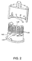
- Figure 2 is a cut-away view of the needle mount and needle hub shown in Figure 1.
- Figure 3 is a three-dimensional view of a needle assembly and needle mount according to a second embodiment of the present invention.
- Figure 4 illustrates the embodiment of Figure 3 when viewed from below.
- Figure 5 is a cut-way view of the needle assembly of Figures 3-4.
- Figure 6 is an enlarged view of the needle assembly mounting means of the embodiment shown in Figures 3-5.
- Figure 7 is a cut through view of the needle mount and needle hub illustrating one embodiment of the present invention for tacitly determining whether the needle hub is securely mounted on the needle mount.
- Figure 8 is a side view of a magazine for storing needles that may be used in practicing the method steps of the present invention.
- Figure 9 is a top view of the magazine shown in Figure 8.
- The present invention provides for systems and methods for attaching needle hub assemblies to ampoules and injection devices. Typically, a needle hub assembly comprises a
needle 510 mounted to a hub 500 (see e.g. Figure 3). As is shown in Figure 1, aneedle hub 10 may be generally cylindrically shaped and have aninterior wall surface 20. In one embodiment of the present invention, a plurality ofprotrusions 30 extends radially inward from theinterior surface 20. - A
needle mount 100 is designed to accept theneedle hub 10. (See e.g. Fig. 1). As is shown in Figures 1 and 2, theneedle mount 100 may be generally cylindrically shaped and have anexterior wall surface 110. A plurality of grooves orslots 120 are disposed in theexterior surface 110. Thegrooves 120 have afirst end 122 and asecond end 125. Thegrooves 120 have afirst portion 130 that defines a passageway that is generally parallel to thecylindrical axis 1000 of theneedle mount 100. While the first portion of thegroove 130 is shown in the drawings as having a rectangular portion, the exact shape of the groove is not critical so long as it allows theprotrusions 30 on the needle hub to move in a direction parallel to thecylindrical axis 1000. Thus, while the groove may have walls that are not necessarily parallel to thecylindrical axis 1000, the groove may still be said to be parallel to the cylindrical axis if it allows theprotrusions 30 to move in a direction parallel to the cylindrical axis. The first portion of thegrooves 130 may have width that is wider than the remainder of the first portion or the remainder of thegroove 130. In embodiments where the groove has walls that are not parallel to thecylindrical axis 1000, the width of the first portion of thegroove 130 may be the average width for the first portion of thegroove 130. - The
first portion 130 may have anentrance 135 that has a width dimension that is greater than the average width of the first portion or is wider than the average width of theentire groove 120. Theentrance 135 may act as an alignment means for aligning the needle hub so that the protrusions will enter thegroove 120. In most embodiments, but not all, the entrance width is wider than any other point in thegroove 120. Typically the width of the groove narrows as the groove is traversed away from theentrance 135. As is shown, the groove may reach a constant width at some distance from the opening. In some embodiments the width of thefirst portion 130 is widest at theentrance 135 and continues to narrow over the length of thefirst portion 130. The grooves also have asecond portion 150 that is either perpendicular to thecylindrical axis 1000, or lies at angle to thefirst portion 130. In some embodiments of the present invention thesecond portion 150 may be comprised of only one surface that is generally perpendicular to the cylindrical axis of the needle mount. Thus, the second portion of thegroove 150 need not be a slot having two sides, but needs only one side to prevent protrusions on the needle hub from moving toward the outer end of the needle mount. As shown in Figure 1, thegrooves 120 may also have athird portion 160 that is oriented at an angle to thefirst portion 130 and thesecond portion 150. - In some embodiments of the present invention a means for tacitly determining whether the needle assembly is securely fixed to the hub is provided. This may be accomplished in numerous different ways, including providing a small projection(s) 439 at the side or in the bottom of the second portion of the
grooves 120. (See e.g. Figure 7). Theprotrusions 30 have to overcome theprojections 439 before the needle is fixed. The deformation of the projections may cause a tacitly feel or a sound, such as a clicking sound. Thus, in some embodiments of the present invention, the needle mounting system can be designed so that the needle hub and the needle mount generate a clicking sound when the needle is securely placed on the mount. When the hub is to be remounted from injection device the oblique tactile protrusions can be more sharp at their ends, so that hub is better fixed during injection and handling etc. This also makes it possible for the patient to keep the needle for more injection. - One advantage of the present invention is that the needle mount, may be equipped with
standard threads 200 on its exterior surface. (See Fig. 1). Thegrooves 120 may be cut into thestandard threads 200. This allows theneedle mount 100 to accept not only needle hubs of the present invention, but also standard, threaded needle-hub assemblies. - While Figure 1 shows the grooves on the needle mount and the protrusions on the needle hub, the present invention may be configured with the grooves located on the interior surface of the needle hub and the protrusions extending outward from the exterior wall of the needle mount. In some, embodiments it may be advantageous to size and shape the protrusions so that they fit between standard threads used with existing needle hubs. The protrusions may then be arranged on the exterior wall of the needle mount to allow not only needle hub assemblies having grooves in their interior wall to be attached, but also standard, threaded needle hubs.
- The present invention may take numerous other forms, including - but not limited to - that shown in Figures 3-6. As is shown in Figures 3-6. the
needle hub assembly 500 has aneedle 510 mounted thereto. Theneedle hub 550 may be generally cylindrically shaped and has aninterior wall surface 600 and a closedtop end 610. The closedtop end 610 has aninside surface 620. Acylindrical member 650 protrudes from theinside surface 620 and has anouter surface 660. See Fig. 5.Protrusions 670 extend radially outward from theouter surface 660. The protrusions may take various forms and shapes, including the triangular prism shape shown in the drawings. - The needle hub assembly shown in Figures 3-5 may be used with a modified needle mount, 700. As is shown in Figures 3 - 6, the
needle mount 700 may be generally cylindrically shaped and have a top end, an interior surface, an exterior surface, and a plurality of locking elements (which may be additional protrusions) extending from the interior surface inward. The locking elements may be arranged to form passageways for theprotrusions 500 on the needle mount, thereby forming a plurality of grooves for accepting the protrusions from theneedle hub assembly 500. As is shown in Fig. 6, the grooves may have afirst portion 561 that defines a passageway that is generally parallel to the cylindrical axis of the needle mount, asecond portion 571 that is perpendicular to the cylindrical axis and athird portion 588 that connects the second 571 andfirst portions 561. Thefirst portion 561 may be widest at its opening and thus act as an alignment mechanism for the protrusions on the needle hub. The needle mount may have a mountingsurface 581 on which a portion of the needle hub rests when the needle hub is mounted on the needle mount. The mounting surface may be a top edge of the top end of needle mount, or it may be theexterior wall surface 599 of the needle mount or both. The embodiment shown in Figures 2-4 also advantageously allows the outer surface of the needle mount to have threads so that standard prior-art needle hubs may be used with the improved needle mount of the present invention. - The present invention enables various methods for attaching a needle-hub assembly to an ampoule or injection device. For example, in one embodiment of the present invention, a needle mount is inserted into a needle hub, the needle hub is rotate relative to the needle mount less than one revolution - typically between 5 and 30 to 60 degrees. In some embodiments, a clicking noise or vibration or other tactile feedback will be provided to indicate that the needle is securely mounted to the hub. In some embodiments little rotation is necessary. In some embodiments, it is possible that no rotation is needed. The surface of the
locking element 777 could simply force the hub to rotate upon insertion of the mount into the interior of thehub 500. In other embodiments, more rotation may be required. - Because the methods of mounting a needle hub to a needle mount do not require that the hub be rotated a full revolution relative to the mount (i.e. either the hub is rotated and the mount is held stationary or the mount is rotated and the hub is held stationary, or both are turned in opposite direction), the present invention enables and provides for methods of mounting needle-hub assemblies stored in magazines, similar to that shown in Figures 8 and 9, to injection devices where their shape would not allow the device to be rotated relative to the magazine by a full revolution. In one embodiment of the present invention, a portion of an
injection device 3000, usually the portion containing aneedle mount 3010, is inserted into aneedle magazine 3050. Thedevice 3000, without being rotated a full revolution is then removed with a needle fully attached to it. In some embodiments audible or tactile feedback is provided to indicate that the need is securely mounted to the device. In some embodiments, the portion of the device that is inserted into the magazine may be an end portion of an ampoule that extends from the device. Some methods of practicing the present invention may be performed using the needles are stored in a magazine having a flush surface 3070 and the needle andhub assemblies 3080 are located below the surface 3070, usually - but not necessarily - in recessed cavities 3090 (see Figure 9). - The foregoing is a brief description of some exemplary embodiments of the present invention and is intended to be illustrative and not exhaustive of the present invention. Those of skill in the art will recognize the nature of language makes it impossible to capture the essence of all aspects of the present invention and unimportant and insubstantial substitutes for various elements are intended to be included within the scope of the invention as defined by the following claims.
-
- A) A needle mounting system for mounting a needle assembly (500) onto a needle mount (100, 700) of an injection device comprising a needle assembly (500), and a needle mount (100, 700), wherein one of the needle assembly (500) or the needle mount (100, 700) is provided with a plurality of protrusions (30, 670) and the other of the needle assembly (500) or the needle mount (100, 700) is provided with a plurality of grooves (120, 588) and wherein the protrusions (30, 670) interacts with the grooves (120, 588).
- B) A needle mounting system according to example A), wherein at least one groove (120, 588) comprises a first portion (130, 561) and a second portion (150, 571).
- C) A needle mounting system according to example B), wherein the needle assembly comprises:
- a hub (10) that is attached to a needle (510), the hub (10) comprising an interior cylindrical wall (20), the plurality of protrusions (30) extending radially inward from the interior cylindrical wall (20) of the hub (10), and the needle mount (100) comprises:
- a cylindrical outer wall (110) having a top end, the plurality of grooves (120) disposed in the cylindrical outer wall (110), the first portion (130) of the grooves (120) beginning at the top end of the cylindrical outer wall (110) and defining a passage way that is generally parallel to a cylindrical axis (1000) of the cylindrical outer wall (110), and the second portion (150) oriented at an angle to the first portion (130).
- a hub (10) that is attached to a needle (510), the hub (10) comprising an interior cylindrical wall (20), the plurality of protrusions (30) extending radially inward from the interior cylindrical wall (20) of the hub (10), and the needle mount (100) comprises:
- D) A needle mounting system according to example C, wherein the angle between the first portion (130) and the second portion (150) is 90 degrees or less.
- E) A needle mounting system according to example C) or D), wherein the first portion (130) of the groove (120) is widest at the top end of the needle mount (100) defining an entrance (135).
- F) A needle mounting system according anyone of the examples C) to E), wherein the protrusions (30) comprises a circular surface.
- G) A needle mounting system according to anyone of the examples C) to F), wherein it further comprises threads (200) disposed on the cylindrical outer wall (110) of the needle mount (100).
- H) A needle mounting system according to anyone of the examples C) to G), wherein it further comprises a means for tactilely and/or audibly determining whether the needle hub (10) is securely mounted on the needle mount (100).
- I) A needle mounting system according to example B), wherein the needle assembly comprises:
- a needle (510) mounted in the hub (550), the hub (550) comprising an inner cylindrical hub wall (600), a top portion, a cylindrical element (650) located within the inner cylindrical wall (600) and having its own cylindrical outer wall (660) that faces the inner hub wall (600), a plurality of protrusions (670) extending radially outward from the outer wall (660) of the cylindrical element (650), and a needle mount comprises:
- an interior cylindrical wall having a top end, a plurality of locking elements (777) disposed on the interior wall of the needle mount (700), the locking elements (777) arranged to form a plurality of first portions (561) beginning at the top end of the interior cylindrical wall and defining a passageway that are substantially parallel to a cylindrical axis (1000) of the interior wall, at least some of the locking elements (777) having a surface that is oriented an angle to the first portion (561), thereby defining a second portion (571).
- a needle (510) mounted in the hub (550), the hub (550) comprising an inner cylindrical hub wall (600), a top portion, a cylindrical element (650) located within the inner cylindrical wall (600) and having its own cylindrical outer wall (660) that faces the inner hub wall (600), a plurality of protrusions (670) extending radially outward from the outer wall (660) of the cylindrical element (650), and a needle mount comprises:
- J) A needle mounting system according to example I), wherein the angle between the first portion (130) and the second portion (150) is 90 degrees or less.
- K) A needle mounting system according to example I) or J), wherein the first passageways (561) is widest at the top end of the needle mount defining an entrance.
- L) A needle mounting system according to anyone of the examples I) to K), wherein the protrusions (570) comprises a triangular surface.
- M) A needle mounting system according to anyone of the examples I) to L), wherein it further comprises threads (200) disposed on the cylindrical outer wall (110) of the needle mount (100).
- N) A needle mounting system according to anyone of the examples I) to M), wherein it further comprises a means (439) for tactilely and/or audibly determining whether the needle hub (10) is securely mounted on the needle mount (100).
- O) A needle mounting system according to anyone of the preceding examples wherein the needle mount (100, 700) is an integral part of an ampoule, a part of an adapter top for an ampoule or part of an injection device.
- P) An injection needle assembly for use in a needle mounting system according to anyone of the examples C) to H), wherein the injection needle assembly comprises a hub (10) that is attached to a needle (510), the hub (10) comprising an interior cylindrical wall (20) having a plurality of protrusions (30) extending radially inward from the interior cylindrical wall (20) of the hub (10).
- Q) A needle mount for use in a needle mounting system according to anyone of the examples C) to H), wherein the needle mount (100) comprises a cylindrical outer wall (110) having a top end and a plurality of grooves (120) disposed in the cylindrical outer wall (110), the grooves (120) having a first portion (130) beginning at the top end of the cylindrical outer wall (110) and defining a passages way that is generally parallel to a cylindrical axis (1000) of the cylindrical outer wall (110) and a second portion (150) oriented at an angle to the first portion (130).
- R) An injection needle assembly for use in a needle mounting system according to anyone of the examples I) to N), wherein the injection needle assembly comprises a needle (510) mounted in a hub (550), the hub (550) comprising an inner cylindrical hub wall (600), a top portion and a cylindrical element (650) located within the inner cylindrical hub wall (600) having its own cylindrical outer wall (660) that faces the inner hub wall (600) bearing a plurality of protrusions (670) extending radially from the outer wall (660) of the cylindrical element (650).
- S) A needle mount for use in a needle mounting system according to anyone of the examples I) to N), wherein the needle mount comprises an interior cylindrical wall having a top end and a plurality of locking elements (777) disposed on the interior wall of the needle mount (700), the locking elements (777) arranged to form a plurality of first portions (561) beginning at the top end of the interior cylindrical wall and defining a passagesway that are substantially parallel to a cylindrical axis (1000) of the interior wall, at least some of the locking elements (777) having a surface that is oriented an angle to the first portion (561), thereby defining a second portion (571).
- T) A method for mounting a needle assembly (500) to an injection device, wherein the method comprises the steps of:
- i) inserting a portion (3010) of an injection device (3000) into a magazine (3050) containing a plurality of needle assemblies (500), and
- ii) rotating the injection device (3000) relative to the needle assembly (500) less than a full revolution,
- iii) removing the portion (3010) of the injection device (3000) from the magazine (3050) with the needle assembly (500) fully attached to the injection device.
- U) A method for removing a needle assembly (500) from an injection device, wherein the method comprises the steps of:
- i) inserting at least a portion (3010) of an injection device (3000) into a magazine (3050) containing a plurality of needle assemblies (500), and
- ii) rotating the injection device (3000) relative to the magazine (3050) less than one full revolution
- iii) remove the portion (3010) of the injection device (3000) from the magazine (3050) with the needle assembly (500) fully detached from the injection device.
Claims (10)
- A needle mount (100) comprising;A cylindrical outer wall (110) having a top end and threads (200) disposed on the cylindrical outer wall (110) for accepting thereon a standard threaded needle assembly, and a plurality of grooves (120) disposed in the cylindrical outer wall (110) beginning at the end of the cylindrical outer wall (11) and defining a passageway that is generally parallel to a cylindrical axis (1000) of the cylindrical outer wall (110),Characterized in that,
at least one groove (120) of the needle mount (100) further comprises a first portion (130) and a second portion (150) oriented at an angle to the first portion (130). - A needle mount (100) according to claim 1, characterized in that, the angle between the first portion (130) and the second portion (150) is 90 degrees or less.
- A needle mount (100) according to claim 1 or 2, characterized in that, the groove (120) is widest at the top end of the needle mount (100) forming an entrance (135).
- A needle assembly (500) comprising;A hub (10) attached to a needle (510), the hub (10) having an interior cylindrical wall (20) with a plurality of protrusions (30) extending radially inward from the interior cylindrical wall (20) wherein a part of the needle (510) is located inside the boundaries of the interior cylindrical wall (20).
- A needle assembly (500) according to claim 4, characterized in that, the protrusions (30) comprises a circular surface.
- A needle assembly (500) according to claim 4 or 5, characterized in that, the protrusions (30) extends perpendicular to a cylindrical axis (1000)
- A needle assembly (500) according to anyone of the claims 4 to 6, characterized in that, the protrusions (30) are located in the proximity of a proximal end of the hub (10) opposite the top end.
- A method for mounting a needle assembly (500) according to claim 4 to a needle mount (100) according to claim 1, the method comprising the steps of:i) inserting the needle mount (100) into the interior of the hub (10) such that the protrusions (30) engages the grooves (120) and the part of the needle located within the boundaries of the interior cylindrical wall (20) enters into the needle mount (100) following the cylindrical axis (1000),ii) partially rotating the needle mount (100) and the needle assembly (500) relative to each other.
- A method for mounting a needle assembly (500) according to claim 8, characterized in that, the needle mount (120) and the needle assembly (500) are rotated less than one revolution relative to each other.
- A method for mounting a needle assembly (500) according to claim 9, characterized in that, the needle mount (120) and the needle assembly (500) are rotated between 5 and 30 to 60 degrees relative to each other.
Applications Claiming Priority (3)
| Application Number | Priority Date | Filing Date | Title |
|---|---|---|---|
| US39408302P | 2002-07-03 | 2002-07-03 | |
| DKPA200201169 | 2002-08-01 | ||
| EP03762466A EP1536854B1 (en) | 2002-07-03 | 2003-06-30 | A needle mounting system for mounting a needle assembly |
Related Parent Applications (1)
| Application Number | Title | Priority Date | Filing Date |
|---|---|---|---|
| EP03762466A Division EP1536854B1 (en) | 2002-07-03 | 2003-06-30 | A needle mounting system for mounting a needle assembly |
Publications (3)
| Publication Number | Publication Date |
|---|---|
| EP1747789A2 true EP1747789A2 (en) | 2007-01-31 |
| EP1747789A3 EP1747789A3 (en) | 2007-12-26 |
| EP1747789B1 EP1747789B1 (en) | 2009-08-19 |
Family
ID=30116818
Family Applications (2)
| Application Number | Title | Priority Date | Filing Date |
|---|---|---|---|
| EP06121820A Expired - Lifetime EP1747789B1 (en) | 2002-07-03 | 2003-06-30 | A needle mount and use of the needle mount for mounting a needle assembly |
| EP03762466A Expired - Lifetime EP1536854B1 (en) | 2002-07-03 | 2003-06-30 | A needle mounting system for mounting a needle assembly |
Family Applications After (1)
| Application Number | Title | Priority Date | Filing Date |
|---|---|---|---|
| EP03762466A Expired - Lifetime EP1536854B1 (en) | 2002-07-03 | 2003-06-30 | A needle mounting system for mounting a needle assembly |
Country Status (13)
| Country | Link |
|---|---|
| EP (2) | EP1747789B1 (en) |
| JP (1) | JP4472522B2 (en) |
| CN (1) | CN100502968C (en) |
| AT (2) | ATE439883T1 (en) |
| AU (1) | AU2003243922B2 (en) |
| CA (1) | CA2491356C (en) |
| DE (2) | DE60309479T2 (en) |
| DK (2) | DK1536854T3 (en) |
| ES (2) | ES2331202T3 (en) |
| PL (1) | PL206471B1 (en) |
| PT (1) | PT1536854E (en) |
| RU (1) | RU2318541C2 (en) |
| WO (1) | WO2004004812A1 (en) |
Cited By (6)
| Publication number | Priority date | Publication date | Assignee | Title |
|---|---|---|---|---|
| WO2008107199A1 (en) * | 2007-03-07 | 2008-09-12 | Novo Nordisk A/S | Back needle |
| US8632503B2 (en) | 2008-03-13 | 2014-01-21 | Becton, Dickinson And Company | Safety pen needle assembly having shielding for patient and non-patient ends |
| US8801673B2 (en) | 2008-03-13 | 2014-08-12 | Becton Dickinson & Company | Safety pen needle assembly having shield for non-patient end |
| US9623194B2 (en) | 2013-12-10 | 2017-04-18 | Becton, Dickinson And Company | Passive safety pen needle assembly |
| US9642971B2 (en) | 2008-03-13 | 2017-05-09 | Becton, Dickinson And Company | Safety needle assembly |
| US9649452B2 (en) | 2013-12-10 | 2017-05-16 | Becton, Dickinson And Company | Active safety pen needle assembly |
Families Citing this family (49)
| Publication number | Priority date | Publication date | Assignee | Title |
|---|---|---|---|---|
| US7654986B2 (en) | 2002-07-03 | 2010-02-02 | Novo Nordisk A/S | Needle mounting system and a method for mounting a needle assembly |
| WO2008008694A2 (en) | 2006-07-11 | 2008-01-17 | Eli Lilly And Company | Needle mounting assembly for a medication injection device |
| US20080033370A1 (en) * | 2006-08-03 | 2008-02-07 | Becton, Dickinson And Company | Binary needle attachment mechanisms |
| BRPI0720777A2 (en) | 2006-12-22 | 2014-07-01 | Novo Nordisk As | NEEDLE SET TO BE PROTECTED WITH INCLINED SAFETY PROTECTOR |
| USD675316S1 (en) | 2007-08-22 | 2013-01-29 | Novo Nordisk A/S | Needle hub |
| WO2009027540A1 (en) * | 2007-08-30 | 2009-03-05 | Novo Nordisk A/S | Bayonet connector for medical injection device and cartridge |
| DE102008025011B4 (en) | 2008-05-24 | 2022-12-22 | Tecpharma Licensing Ag | Ampoule with ampoule holder |
| DE102008025023A1 (en) * | 2008-05-24 | 2009-11-26 | Tecpharma Licensing Ag | Needle unit with rotatable lancing means |
| DE102008025012A1 (en) * | 2008-05-24 | 2009-11-26 | Tecpharma Licensing Ag | Needle unit with rotation stop |
| EP2355877B1 (en) * | 2008-12-12 | 2016-11-16 | SHL Group AB | Delivery member attachment device |
| CN102341139B (en) * | 2009-03-03 | 2014-06-04 | 诺沃—诺迪斯克有限公司 | Cap lock |
| US8529518B2 (en) * | 2009-06-12 | 2013-09-10 | Novo Nordisk A/S | Drug delivery device with cap functions for needle assembly |
| BR112012022296A2 (en) | 2010-03-05 | 2017-10-31 | Novo Nordisk As | hinged two-piece needle case. |
| JP5864527B2 (en) * | 2010-03-26 | 2016-02-17 | サノフィ−アベンティス・ドイチュラント・ゲゼルシャフト・ミット・ベシュレンクテル・ハフツング | Dedicated needle assembly |
| US8876780B2 (en) | 2010-08-16 | 2014-11-04 | Becton, Dickinson And Company | Attachable needle changing device for medicament delivery device |
| US9427514B2 (en) | 2010-08-16 | 2016-08-30 | Becton, Dickinson And Company | Needle changing apparatus |
| US9107988B2 (en) * | 2010-08-16 | 2015-08-18 | Becton, Dickinson And Company | Circuitous band needle changing apparatus |
| WO2012089821A1 (en) | 2010-12-31 | 2012-07-05 | Novo Nordisk A/S | Medical injection device |
| EP2476450A1 (en) | 2011-08-29 | 2012-07-18 | Novo Nordisk A/S | A pen needle container and a method for bending a needle cannula |
| KR200459325Y1 (en) | 2011-10-04 | 2012-03-22 | 조봉익 | Dental injector having detachable needle |
| US20140243761A1 (en) | 2011-11-03 | 2014-08-28 | Novo Nordisk A/S | Process for Shaping a Needle Cannula |
| DK2814546T3 (en) * | 2012-02-13 | 2020-08-24 | Sanofi Aventis Deutschland | PENTYPE INJECTION DEVICE AND ELECTRONIC ATTACHMENT MODULE THEREOF |
| WO2013139497A1 (en) | 2012-03-22 | 2013-09-26 | Novo Nordisk A/S | Revolving needle magazine |
| WO2014001319A1 (en) | 2012-06-29 | 2014-01-03 | Novo Nordisk A/S | Spring driven injection device |
| CN104736188B (en) | 2012-10-15 | 2017-09-01 | 诺和诺德股份有限公司 | Spring driven injection device |
| CN104768598B (en) | 2012-10-25 | 2018-04-06 | 诺和诺德股份有限公司 | Pre-filled disposable syringe device |
| EP2732835A1 (en) * | 2012-11-14 | 2014-05-21 | Sanofi-Aventis Deutschland GmbH | Needle assembly magazine |
| EP2956192B1 (en) | 2013-02-18 | 2020-08-05 | Novo Nordisk A/S | Injection needle having shield activated valve |
| CN103522049B (en) * | 2013-09-29 | 2016-02-17 | 无锡众望四维科技有限公司 | The pin-packaging device of syringe pointer assembling machine |
| US10335535B2 (en) | 2013-10-31 | 2019-07-02 | Novo Nordisk A/S | Injection device with a needle cannula |
| US20160317745A1 (en) | 2014-01-03 | 2016-11-03 | Novo Nordisk A/S | Auto-Injection Device with Button Activation |
| EP3102255A1 (en) | 2014-02-06 | 2016-12-14 | Novo Nordisk A/S | A cartridge and needle assembly in combination |
| CN106456888B (en) | 2014-06-26 | 2019-12-31 | 诺和诺德股份有限公司 | Pen-shaped torsion spring driving injection device |
| KR101610322B1 (en) | 2014-07-31 | 2016-04-20 | 백우인 | Jig for adjustmening needle of syringe |
| WO2016055505A1 (en) | 2014-10-08 | 2016-04-14 | Novo Nordisk A/S | A torsion spring for an injection device and an injection device comprising such torsion spring |
| US9199033B1 (en) | 2014-10-28 | 2015-12-01 | Bayer Healthcare Llc | Self-orienting syringe and syringe interface |
| RU2017118366A (en) | 2014-10-28 | 2018-11-30 | БАЙЕР ХелсКер ЛЛСи | HIGH-PRESSURE SELF-ORIENTATING CASING AND HIGH PRESSURE CASING JOINING MECHANISM AND INJECTOR |
| NO2689315T3 (en) * | 2014-10-28 | 2018-04-14 | ||
| CN107106761B (en) * | 2014-10-28 | 2020-11-03 | 拜耳医药保健有限公司 | Self-orienting pressure jacket and interface of pressure jacket to syringe |
| CN107106777B (en) | 2014-12-22 | 2020-10-02 | 诺和诺德股份有限公司 | Injection device with removable cap |
| US10835674B2 (en) | 2015-11-13 | 2020-11-17 | Bayer Healthcare Llc | Nested syringe assembly |
| WO2017084976A1 (en) | 2015-11-19 | 2017-05-26 | Novo Nordisk A/S | A shielded needle cannula |
| WO2017174433A1 (en) | 2016-04-05 | 2017-10-12 | Novo Nordisk A/S | A torsion spring driven injection device |
| WO2019106157A1 (en) | 2017-12-01 | 2019-06-06 | Novo Nordisk A/S | Crystal-free oscillator for channel-based high-frequency radio communication |
| US11191893B2 (en) | 2018-01-31 | 2021-12-07 | Bayer Healthcare Llc | System and method for syringe engagement with injector |
| CN108905252B (en) * | 2018-06-11 | 2021-02-19 | 江西国药有限责任公司 | Drying method in production process of fermented cordyceps sinensis powder |
| CN111282092B (en) * | 2020-02-15 | 2021-11-16 | 湖州师范学院 | Automatic injection intelligent magnetic drive needle mounting mechanism |
| KR102466109B1 (en) * | 2020-05-07 | 2022-11-14 | 전북대학교산학협력단 | A device changes the tip of syringe to use single syringe regardless the purposes to treat |
| KR102451560B1 (en) * | 2021-03-24 | 2022-10-07 | (주)글로벌메디칼 | Hybrid Catheter Kit |
Citations (6)
| Publication number | Priority date | Publication date | Assignee | Title |
|---|---|---|---|---|
| US1757680A (en) * | 1929-02-08 | 1930-05-06 | James B Neil | Needle-locking device for syringes |
| GB594366A (en) * | 1944-05-26 | 1947-11-10 | Mizzy Inc | Improvement in hypodermic syringe |
| CH332340A (en) * | 1955-07-21 | 1958-08-31 | Victor Chaudon Maurice | Fixation device for a hypodermic needle |
| EP0055859A2 (en) * | 1980-12-30 | 1982-07-14 | Walter Sarstedt Kunststoff-Spritzgusswerk | Blood sampling device |
| WO1996011028A1 (en) * | 1994-10-11 | 1996-04-18 | Ian Marshall Moore | Single use syringe |
| WO2002011798A1 (en) * | 2000-08-03 | 2002-02-14 | Novo Nordisk A/S | A needle magazine |
Family Cites Families (12)
| Publication number | Priority date | Publication date | Assignee | Title |
|---|---|---|---|---|
| US2842126A (en) * | 1954-03-16 | 1958-07-08 | Frederick M Turnbull | Syringe assembly |
| JPS6346148U (en) * | 1986-09-10 | 1988-03-29 | ||
| EP0304619B1 (en) * | 1987-07-31 | 1991-10-16 | Nissho Corporation | Injection needle-detaching device and container having said device |
| JPH0387433A (en) * | 1989-08-31 | 1991-04-12 | Osami Kato | Assembling structure for framework members |
| JP2504907Y2 (en) * | 1991-12-20 | 1996-07-24 | 東洋製罐株式会社 | cap |
| AU669172B2 (en) * | 1992-07-21 | 1996-05-30 | Critikon, Inc. | Interchangeable pneumatic connector for blood pressure monitors |
| CH685677A5 (en) * | 1993-07-09 | 1995-09-15 | Disetronic Ag | Attachment mechanism for needle systems. |
| JP3677757B2 (en) * | 1997-03-18 | 2005-08-03 | 株式会社吉野工業所 | Tube container |
| US6346094B2 (en) * | 1998-09-28 | 2002-02-12 | Becton, Dickinson And Company | Pen needle magazine |
| US6368303B1 (en) * | 1999-10-15 | 2002-04-09 | Becton, Dickinson And Company | Retracting needle syringe |
| US6461328B2 (en) * | 2000-12-21 | 2002-10-08 | Uniqsafe Medical Technology Group Ltd. | Safety syringe |
| DE20101594U1 (en) * | 2001-01-31 | 2001-04-05 | Wella Ag | Container with two threads on the neck of the container |
-
2003
- 2003-06-30 AT AT06121820T patent/ATE439883T1/en not_active IP Right Cessation
- 2003-06-30 RU RU2005102605/14A patent/RU2318541C2/en not_active IP Right Cessation
- 2003-06-30 ES ES06121820T patent/ES2331202T3/en not_active Expired - Lifetime
- 2003-06-30 PL PL374182A patent/PL206471B1/en unknown
- 2003-06-30 CA CA2491356A patent/CA2491356C/en not_active Expired - Fee Related
- 2003-06-30 AU AU2003243922A patent/AU2003243922B2/en not_active Ceased
- 2003-06-30 DK DK03762466T patent/DK1536854T3/en active
- 2003-06-30 DE DE60309479T patent/DE60309479T2/en not_active Expired - Lifetime
- 2003-06-30 DK DK06121820T patent/DK1747789T3/en active
- 2003-06-30 EP EP06121820A patent/EP1747789B1/en not_active Expired - Lifetime
- 2003-06-30 WO PCT/DK2003/000451 patent/WO2004004812A1/en active IP Right Grant
- 2003-06-30 CN CNB038156512A patent/CN100502968C/en not_active Expired - Lifetime
- 2003-06-30 ES ES03762466T patent/ES2276112T3/en not_active Expired - Lifetime
- 2003-06-30 DE DE60328927T patent/DE60328927D1/en not_active Expired - Lifetime
- 2003-06-30 AT AT03762466T patent/ATE344076T1/en active
- 2003-06-30 PT PT03762466T patent/PT1536854E/en unknown
- 2003-06-30 JP JP2004518458A patent/JP4472522B2/en not_active Expired - Lifetime
- 2003-06-30 EP EP03762466A patent/EP1536854B1/en not_active Expired - Lifetime
Patent Citations (6)
| Publication number | Priority date | Publication date | Assignee | Title |
|---|---|---|---|---|
| US1757680A (en) * | 1929-02-08 | 1930-05-06 | James B Neil | Needle-locking device for syringes |
| GB594366A (en) * | 1944-05-26 | 1947-11-10 | Mizzy Inc | Improvement in hypodermic syringe |
| CH332340A (en) * | 1955-07-21 | 1958-08-31 | Victor Chaudon Maurice | Fixation device for a hypodermic needle |
| EP0055859A2 (en) * | 1980-12-30 | 1982-07-14 | Walter Sarstedt Kunststoff-Spritzgusswerk | Blood sampling device |
| WO1996011028A1 (en) * | 1994-10-11 | 1996-04-18 | Ian Marshall Moore | Single use syringe |
| WO2002011798A1 (en) * | 2000-08-03 | 2002-02-14 | Novo Nordisk A/S | A needle magazine |
Cited By (11)
| Publication number | Priority date | Publication date | Assignee | Title |
|---|---|---|---|---|
| WO2008107199A1 (en) * | 2007-03-07 | 2008-09-12 | Novo Nordisk A/S | Back needle |
| CN101626796B (en) * | 2007-03-07 | 2013-02-06 | 诺沃-诺迪斯克有限公司 | Back needle |
| US9125601B2 (en) | 2007-03-07 | 2015-09-08 | Novo Nordisk A/S | Back needle |
| US8632503B2 (en) | 2008-03-13 | 2014-01-21 | Becton, Dickinson And Company | Safety pen needle assembly having shielding for patient and non-patient ends |
| US8801673B2 (en) | 2008-03-13 | 2014-08-12 | Becton Dickinson & Company | Safety pen needle assembly having shield for non-patient end |
| US9162030B2 (en) | 2008-03-13 | 2015-10-20 | Becton, Dickinson And Company | Safety pen needle assembly having shielding for patient and non-patient ends |
| US9642971B2 (en) | 2008-03-13 | 2017-05-09 | Becton, Dickinson And Company | Safety needle assembly |
| US10322250B2 (en) | 2008-03-13 | 2019-06-18 | Becton, Dickinson And Company | Safety needle assembly |
| US10398858B2 (en) | 2008-03-13 | 2019-09-03 | Becton, Dickinson And Company | Safety needle assembly |
| US9623194B2 (en) | 2013-12-10 | 2017-04-18 | Becton, Dickinson And Company | Passive safety pen needle assembly |
| US9649452B2 (en) | 2013-12-10 | 2017-05-16 | Becton, Dickinson And Company | Active safety pen needle assembly |
Also Published As
| Publication number | Publication date |
|---|---|
| ATE439883T1 (en) | 2009-09-15 |
| ES2276112T3 (en) | 2007-06-16 |
| WO2004004812A1 (en) | 2004-01-15 |
| CN100502968C (en) | 2009-06-24 |
| DK1747789T3 (en) | 2009-11-30 |
| ES2331202T3 (en) | 2009-12-23 |
| EP1536854B1 (en) | 2006-11-02 |
| EP1747789A3 (en) | 2007-12-26 |
| DK1536854T3 (en) | 2007-02-26 |
| PL206471B1 (en) | 2010-08-31 |
| EP1747789B1 (en) | 2009-08-19 |
| CA2491356C (en) | 2011-02-22 |
| JP2006512106A (en) | 2006-04-13 |
| PL374182A1 (en) | 2005-10-03 |
| EP1536854A1 (en) | 2005-06-08 |
| DE60328927D1 (en) | 2009-10-01 |
| DE60309479D1 (en) | 2006-12-14 |
| AU2003243922A1 (en) | 2004-01-23 |
| PT1536854E (en) | 2007-02-28 |
| CN1665558A (en) | 2005-09-07 |
| CA2491356A1 (en) | 2004-01-15 |
| RU2005102605A (en) | 2005-07-20 |
| AU2003243922B2 (en) | 2008-09-25 |
| JP4472522B2 (en) | 2010-06-02 |
| RU2318541C2 (en) | 2008-03-10 |
| DE60309479T2 (en) | 2007-08-16 |
| ATE344076T1 (en) | 2006-11-15 |
Similar Documents
| Publication | Publication Date | Title |
|---|---|---|
| EP1536854B1 (en) | A needle mounting system for mounting a needle assembly | |
| US8137325B2 (en) | Needle mounting system and a method for mounting a needle assembly | |
| TWI487546B (en) | Injection device for dispensing a medicament | |
| EP2517746A1 (en) | Needle assembly storage system | |
| US10052438B2 (en) | Tamper evident needle guard for syringes | |
| US7875007B2 (en) | Syringe accessory | |
| JP5897007B2 (en) | Cartridge holder and method for assembling a cartridge unit for a drug delivery device | |
| EP2522379A1 (en) | Needle assembly storage device | |
| US10780234B2 (en) | Dental syringe with stabilizer for removable needle | |
| US10729854B2 (en) | Housing for mounting a container on an injection pen, assembly forming an injectable product reservoir for an injection pen and injection pen equipped with such an assembly | |
| JP2018187138A (en) | Container for disposing of needle unit of pen-type syringe | |
| JP2018175474A (en) | Medical waste container and disposal system | |
| EP2559447A1 (en) | Single-use needle assembly and storage device |
Legal Events
| Date | Code | Title | Description |
|---|---|---|---|
| PUAI | Public reference made under article 153(3) epc to a published international application that has entered the european phase |
Free format text: ORIGINAL CODE: 0009012 |
|
| AC | Divisional application: reference to earlier application |
Ref document number: 1536854 Country of ref document: EP Kind code of ref document: P |
|
| AK | Designated contracting states |
Kind code of ref document: A2 Designated state(s): AT BE BG CH CY CZ DE DK EE ES FI FR GB GR HU IE IT LI LU MC NL PT RO SE SI SK TR |
|
| RIN1 | Information on inventor provided before grant (corrected) |
Inventor name: NIELSEN, JAN FRANK Inventor name: RADMER, JIM Inventor name: MOELLER JENSEN, JENS Inventor name: SMEDEGAARD, JORGEN K. Inventor name: KLINT, HENDRIK SOENDERSKOV Inventor name: MOELLER JENSEN, PETER |
|
| PUAL | Search report despatched |
Free format text: ORIGINAL CODE: 0009013 |
|
| AK | Designated contracting states |
Kind code of ref document: A3 Designated state(s): AT BE BG CH CY CZ DE DK EE ES FI FR GB GR HU IE IT LI LU MC NL PT RO SE SI SK TR |
|
| 17P | Request for examination filed |
Effective date: 20080626 |
|
| 17Q | First examination report despatched |
Effective date: 20080729 |
|
| AKX | Designation fees paid |
Designated state(s): AT BE BG CH CY CZ DE DK EE ES FI FR GB GR HU IE IT LI LU MC NL PT RO SE SI SK TR |
|
| GRAP | Despatch of communication of intention to grant a patent |
Free format text: ORIGINAL CODE: EPIDOSNIGR1 |
|
| RTI1 | Title (correction) |
Free format text: A NEEDLE MOUNT AND USE OF THE NEEDLE MOUNT FOR MOUNTING A NEEDLE ASSEMBLY |
|
| GRAS | Grant fee paid |
Free format text: ORIGINAL CODE: EPIDOSNIGR3 |
|
| GRAA | (expected) grant |
Free format text: ORIGINAL CODE: 0009210 |
|
| AC | Divisional application: reference to earlier application |
Ref document number: 1536854 Country of ref document: EP Kind code of ref document: P |
|
| AK | Designated contracting states |
Kind code of ref document: B1 Designated state(s): AT BE BG CH CY CZ DE DK EE ES FI FR GB GR HU IE IT LI LU MC NL PT RO SE SI SK TR |
|
| REG | Reference to a national code |
Ref country code: GB Ref legal event code: FG4D |
|
| REG | Reference to a national code |
Ref country code: CH Ref legal event code: EP |
|
| REG | Reference to a national code |
Ref country code: IE Ref legal event code: FG4D |
|
| REF | Corresponds to: |
Ref document number: 60328927 Country of ref document: DE Date of ref document: 20091001 Kind code of ref document: P |
|
| REG | Reference to a national code |
Ref country code: DK Ref legal event code: T3 |
|
| REG | Reference to a national code |
Ref country code: SE Ref legal event code: TRGR |
|
| REG | Reference to a national code |
Ref country code: ES Ref legal event code: FG2A Ref document number: 2331202 Country of ref document: ES Kind code of ref document: T3 |
|
| PG25 | Lapsed in a contracting state [announced via postgrant information from national office to epo] |
Ref country code: AT Free format text: LAPSE BECAUSE OF FAILURE TO SUBMIT A TRANSLATION OF THE DESCRIPTION OR TO PAY THE FEE WITHIN THE PRESCRIBED TIME-LIMIT Effective date: 20090819 Ref country code: FI Free format text: LAPSE BECAUSE OF FAILURE TO SUBMIT A TRANSLATION OF THE DESCRIPTION OR TO PAY THE FEE WITHIN THE PRESCRIBED TIME-LIMIT Effective date: 20090819 |
|
| PG25 | Lapsed in a contracting state [announced via postgrant information from national office to epo] |
Ref country code: SI Free format text: LAPSE BECAUSE OF FAILURE TO SUBMIT A TRANSLATION OF THE DESCRIPTION OR TO PAY THE FEE WITHIN THE PRESCRIBED TIME-LIMIT Effective date: 20090819 |
|
| PG25 | Lapsed in a contracting state [announced via postgrant information from national office to epo] |
Ref country code: BG Free format text: LAPSE BECAUSE OF FAILURE TO SUBMIT A TRANSLATION OF THE DESCRIPTION OR TO PAY THE FEE WITHIN THE PRESCRIBED TIME-LIMIT Effective date: 20091119 Ref country code: CY Free format text: LAPSE BECAUSE OF FAILURE TO SUBMIT A TRANSLATION OF THE DESCRIPTION OR TO PAY THE FEE WITHIN THE PRESCRIBED TIME-LIMIT Effective date: 20090819 Ref country code: PT Free format text: LAPSE BECAUSE OF FAILURE TO SUBMIT A TRANSLATION OF THE DESCRIPTION OR TO PAY THE FEE WITHIN THE PRESCRIBED TIME-LIMIT Effective date: 20091221 |
|
| PG25 | Lapsed in a contracting state [announced via postgrant information from national office to epo] |
Ref country code: EE Free format text: LAPSE BECAUSE OF FAILURE TO SUBMIT A TRANSLATION OF THE DESCRIPTION OR TO PAY THE FEE WITHIN THE PRESCRIBED TIME-LIMIT Effective date: 20090819 Ref country code: RO Free format text: LAPSE BECAUSE OF FAILURE TO SUBMIT A TRANSLATION OF THE DESCRIPTION OR TO PAY THE FEE WITHIN THE PRESCRIBED TIME-LIMIT Effective date: 20090819 Ref country code: CZ Free format text: LAPSE BECAUSE OF FAILURE TO SUBMIT A TRANSLATION OF THE DESCRIPTION OR TO PAY THE FEE WITHIN THE PRESCRIBED TIME-LIMIT Effective date: 20090819 |
|
| PLBI | Opposition filed |
Free format text: ORIGINAL CODE: 0009260 |
|
| PG25 | Lapsed in a contracting state [announced via postgrant information from national office to epo] |
Ref country code: SK Free format text: LAPSE BECAUSE OF FAILURE TO SUBMIT A TRANSLATION OF THE DESCRIPTION OR TO PAY THE FEE WITHIN THE PRESCRIBED TIME-LIMIT Effective date: 20090819 |
|
| PLAX | Notice of opposition and request to file observation + time limit sent |
Free format text: ORIGINAL CODE: EPIDOSNOBS2 |
|
| 26 | Opposition filed |
Opponent name: SANOFI-AVENTIS DEUTSCHLAND GMBH Effective date: 20100518 |
|
| PG25 | Lapsed in a contracting state [announced via postgrant information from national office to epo] |
Ref country code: BE Free format text: LAPSE BECAUSE OF FAILURE TO SUBMIT A TRANSLATION OF THE DESCRIPTION OR TO PAY THE FEE WITHIN THE PRESCRIBED TIME-LIMIT Effective date: 20090819 |
|
| PG25 | Lapsed in a contracting state [announced via postgrant information from national office to epo] |
Ref country code: GR Free format text: LAPSE BECAUSE OF FAILURE TO SUBMIT A TRANSLATION OF THE DESCRIPTION OR TO PAY THE FEE WITHIN THE PRESCRIBED TIME-LIMIT Effective date: 20091120 |
|
| PLAF | Information modified related to communication of a notice of opposition and request to file observations + time limit |
Free format text: ORIGINAL CODE: EPIDOSCOBS2 |
|
| PLBB | Reply of patent proprietor to notice(s) of opposition received |
Free format text: ORIGINAL CODE: EPIDOSNOBS3 |
|
| PG25 | Lapsed in a contracting state [announced via postgrant information from national office to epo] |
Ref country code: MC Free format text: LAPSE BECAUSE OF NON-PAYMENT OF DUE FEES Effective date: 20100630 |
|
| PG25 | Lapsed in a contracting state [announced via postgrant information from national office to epo] |
Ref country code: IE Free format text: LAPSE BECAUSE OF NON-PAYMENT OF DUE FEES Effective date: 20100630 |
|
| PG25 | Lapsed in a contracting state [announced via postgrant information from national office to epo] |
Ref country code: HU Free format text: LAPSE BECAUSE OF FAILURE TO SUBMIT A TRANSLATION OF THE DESCRIPTION OR TO PAY THE FEE WITHIN THE PRESCRIBED TIME-LIMIT Effective date: 20100220 Ref country code: LU Free format text: LAPSE BECAUSE OF NON-PAYMENT OF DUE FEES Effective date: 20100630 |
|
| PLCK | Communication despatched that opposition was rejected |
Free format text: ORIGINAL CODE: EPIDOSNREJ1 |
|
| APBM | Appeal reference recorded |
Free format text: ORIGINAL CODE: EPIDOSNREFNO |
|
| APBP | Date of receipt of notice of appeal recorded |
Free format text: ORIGINAL CODE: EPIDOSNNOA2O |
|
| APAH | Appeal reference modified |
Free format text: ORIGINAL CODE: EPIDOSCREFNO |
|
| APAW | Appeal reference deleted |
Free format text: ORIGINAL CODE: EPIDOSDREFNO |
|
| APAY | Date of receipt of notice of appeal deleted |
Free format text: ORIGINAL CODE: EPIDOSDNOA2O |
|
| APBM | Appeal reference recorded |
Free format text: ORIGINAL CODE: EPIDOSNREFNO |
|
| APBP | Date of receipt of notice of appeal recorded |
Free format text: ORIGINAL CODE: EPIDOSNNOA2O |
|
| APBQ | Date of receipt of statement of grounds of appeal recorded |
Free format text: ORIGINAL CODE: EPIDOSNNOA3O |
|
| REG | Reference to a national code |
Ref country code: FR Ref legal event code: PLFP Year of fee payment: 14 |
|
| REG | Reference to a national code |
Ref country code: FR Ref legal event code: PLFP Year of fee payment: 15 |
|
| REG | Reference to a national code |
Ref country code: FR Ref legal event code: PLFP Year of fee payment: 16 |
|
| PLAB | Opposition data, opponent's data or that of the opponent's representative modified |
Free format text: ORIGINAL CODE: 0009299OPPO |
|
| R26 | Opposition filed (corrected) |
Opponent name: SANOFI-AVENTIS DEUTSCHLAND GMBH Effective date: 20100518 |
|
| REG | Reference to a national code |
Ref country code: DE Ref legal event code: R100 Ref document number: 60328927 Country of ref document: DE |
|
| APBU | Appeal procedure closed |
Free format text: ORIGINAL CODE: EPIDOSNNOA9O |
|
| PLBN | Opposition rejected |
Free format text: ORIGINAL CODE: 0009273 |
|
| STAA | Information on the status of an ep patent application or granted ep patent |
Free format text: STATUS: OPPOSITION REJECTED |
|
| 27O | Opposition rejected |
Effective date: 20200131 |
|
| PGFP | Annual fee paid to national office [announced via postgrant information from national office to epo] |
Ref country code: NL Payment date: 20220523 Year of fee payment: 20 |
|
| PGFP | Annual fee paid to national office [announced via postgrant information from national office to epo] |
Ref country code: SE Payment date: 20220519 Year of fee payment: 20 Ref country code: IT Payment date: 20220518 Year of fee payment: 20 Ref country code: GB Payment date: 20220520 Year of fee payment: 20 Ref country code: FR Payment date: 20220519 Year of fee payment: 20 Ref country code: DK Payment date: 20220518 Year of fee payment: 20 Ref country code: DE Payment date: 20220518 Year of fee payment: 20 |
|
| PGFP | Annual fee paid to national office [announced via postgrant information from national office to epo] |
Ref country code: TR Payment date: 20220530 Year of fee payment: 20 |
|
| PGFP | Annual fee paid to national office [announced via postgrant information from national office to epo] |
Ref country code: ES Payment date: 20220701 Year of fee payment: 20 |
|
| PGFP | Annual fee paid to national office [announced via postgrant information from national office to epo] |
Ref country code: CH Payment date: 20220702 Year of fee payment: 20 |
|
| REG | Reference to a national code |
Ref country code: DE Ref legal event code: R071 Ref document number: 60328927 Country of ref document: DE Ref country code: CH Ref legal event code: PL |
|
| REG | Reference to a national code |
Ref country code: DK Ref legal event code: EUP Expiry date: 20230630 |
|
| REG | Reference to a national code |
Ref country code: NL Ref legal event code: MK Effective date: 20230629 |
|
| REG | Reference to a national code |
Ref country code: GB Ref legal event code: PE20 Expiry date: 20230629 |
|
| REG | Reference to a national code |
Ref country code: ES Ref legal event code: FD2A Effective date: 20230726 |
|
| REG | Reference to a national code |
Ref country code: SE Ref legal event code: EUG |
|
| PG25 | Lapsed in a contracting state [announced via postgrant information from national office to epo] |
Ref country code: GB Free format text: LAPSE BECAUSE OF EXPIRATION OF PROTECTION Effective date: 20230629 Ref country code: ES Free format text: LAPSE BECAUSE OF EXPIRATION OF PROTECTION Effective date: 20230701 |