EP1748745B1 - Devices, systems, and methods for reshaping a heart valve annulus - Google Patents
Devices, systems, and methods for reshaping a heart valve annulus Download PDFInfo
- Publication number
- EP1748745B1 EP1748745B1 EP05742354.3A EP05742354A EP1748745B1 EP 1748745 B1 EP1748745 B1 EP 1748745B1 EP 05742354 A EP05742354 A EP 05742354A EP 1748745 B1 EP1748745 B1 EP 1748745B1
- Authority
- EP
- European Patent Office
- Prior art keywords
- annulus
- implant
- tissue
- component
- implant system
- Prior art date
- Legal status (The legal status is an assumption and is not a legal conclusion. Google has not performed a legal analysis and makes no representation as to the accuracy of the status listed.)
- Active
Links
Images


Classifications
-
- A—HUMAN NECESSITIES
- A61—MEDICAL OR VETERINARY SCIENCE; HYGIENE
- A61F—FILTERS IMPLANTABLE INTO BLOOD VESSELS; PROSTHESES; DEVICES PROVIDING PATENCY TO, OR PREVENTING COLLAPSING OF, TUBULAR STRUCTURES OF THE BODY, e.g. STENTS; ORTHOPAEDIC, NURSING OR CONTRACEPTIVE DEVICES; FOMENTATION; TREATMENT OR PROTECTION OF EYES OR EARS; BANDAGES, DRESSINGS OR ABSORBENT PADS; FIRST-AID KITS
- A61F2/00—Filters implantable into blood vessels; Prostheses, i.e. artificial substitutes or replacements for parts of the body; Appliances for connecting them with the body; Devices providing patency to, or preventing collapsing of, tubular structures of the body, e.g. stents
- A61F2/02—Prostheses implantable into the body
- A61F2/24—Heart valves ; Vascular valves, e.g. venous valves; Heart implants, e.g. passive devices for improving the function of the native valve or the heart muscle; Transmyocardial revascularisation [TMR] devices; Valves implantable in the body
- A61F2/2442—Annuloplasty rings or inserts for correcting the valve shape; Implants for improving the function of a native heart valve
- A61F2/2445—Annuloplasty rings in direct contact with the valve annulus
-
- A—HUMAN NECESSITIES
- A61—MEDICAL OR VETERINARY SCIENCE; HYGIENE
- A61B—DIAGNOSIS; SURGERY; IDENTIFICATION
- A61B17/00—Surgical instruments, devices or methods, e.g. tourniquets
- A61B17/00234—Surgical instruments, devices or methods, e.g. tourniquets for minimally invasive surgery
-
- A—HUMAN NECESSITIES
- A61—MEDICAL OR VETERINARY SCIENCE; HYGIENE
- A61B—DIAGNOSIS; SURGERY; IDENTIFICATION
- A61B17/00—Surgical instruments, devices or methods, e.g. tourniquets
- A61B17/04—Surgical instruments, devices or methods, e.g. tourniquets for suturing wounds; Holders or packages for needles or suture materials
- A61B17/0401—Suture anchors, buttons or pledgets, i.e. means for attaching sutures to bone, cartilage or soft tissue; Instruments for applying or removing suture anchors
-
- A—HUMAN NECESSITIES
- A61—MEDICAL OR VETERINARY SCIENCE; HYGIENE
- A61B—DIAGNOSIS; SURGERY; IDENTIFICATION
- A61B17/00—Surgical instruments, devices or methods, e.g. tourniquets
- A61B17/064—Surgical staples, i.e. penetrating the tissue
-
- A—HUMAN NECESSITIES
- A61—MEDICAL OR VETERINARY SCIENCE; HYGIENE
- A61B—DIAGNOSIS; SURGERY; IDENTIFICATION
- A61B17/00—Surgical instruments, devices or methods, e.g. tourniquets
- A61B17/00234—Surgical instruments, devices or methods, e.g. tourniquets for minimally invasive surgery
- A61B2017/00238—Type of minimally invasive operation
- A61B2017/00243—Type of minimally invasive operation cardiac
-
- A—HUMAN NECESSITIES
- A61—MEDICAL OR VETERINARY SCIENCE; HYGIENE
- A61B—DIAGNOSIS; SURGERY; IDENTIFICATION
- A61B17/00—Surgical instruments, devices or methods, e.g. tourniquets
- A61B2017/00743—Type of operation; Specification of treatment sites
- A61B2017/00778—Operations on blood vessels
- A61B2017/00783—Valvuloplasty
-
- A—HUMAN NECESSITIES
- A61—MEDICAL OR VETERINARY SCIENCE; HYGIENE
- A61B—DIAGNOSIS; SURGERY; IDENTIFICATION
- A61B17/00—Surgical instruments, devices or methods, e.g. tourniquets
- A61B2017/00831—Material properties
- A61B2017/00876—Material properties magnetic
-
- A—HUMAN NECESSITIES
- A61—MEDICAL OR VETERINARY SCIENCE; HYGIENE
- A61B—DIAGNOSIS; SURGERY; IDENTIFICATION
- A61B17/00—Surgical instruments, devices or methods, e.g. tourniquets
- A61B17/04—Surgical instruments, devices or methods, e.g. tourniquets for suturing wounds; Holders or packages for needles or suture materials
- A61B17/0401—Suture anchors, buttons or pledgets, i.e. means for attaching sutures to bone, cartilage or soft tissue; Instruments for applying or removing suture anchors
- A61B2017/0412—Suture anchors, buttons or pledgets, i.e. means for attaching sutures to bone, cartilage or soft tissue; Instruments for applying or removing suture anchors having anchoring barbs or pins extending outwardly from suture anchor body
-
- A—HUMAN NECESSITIES
- A61—MEDICAL OR VETERINARY SCIENCE; HYGIENE
- A61B—DIAGNOSIS; SURGERY; IDENTIFICATION
- A61B17/00—Surgical instruments, devices or methods, e.g. tourniquets
- A61B17/04—Surgical instruments, devices or methods, e.g. tourniquets for suturing wounds; Holders or packages for needles or suture materials
- A61B17/0401—Suture anchors, buttons or pledgets, i.e. means for attaching sutures to bone, cartilage or soft tissue; Instruments for applying or removing suture anchors
- A61B2017/0414—Suture anchors, buttons or pledgets, i.e. means for attaching sutures to bone, cartilage or soft tissue; Instruments for applying or removing suture anchors having a suture-receiving opening, e.g. lateral opening
-
- A—HUMAN NECESSITIES
- A61—MEDICAL OR VETERINARY SCIENCE; HYGIENE
- A61B—DIAGNOSIS; SURGERY; IDENTIFICATION
- A61B17/00—Surgical instruments, devices or methods, e.g. tourniquets
- A61B17/04—Surgical instruments, devices or methods, e.g. tourniquets for suturing wounds; Holders or packages for needles or suture materials
- A61B17/0401—Suture anchors, buttons or pledgets, i.e. means for attaching sutures to bone, cartilage or soft tissue; Instruments for applying or removing suture anchors
- A61B2017/0417—T-fasteners
-
- A—HUMAN NECESSITIES
- A61—MEDICAL OR VETERINARY SCIENCE; HYGIENE
- A61B—DIAGNOSIS; SURGERY; IDENTIFICATION
- A61B17/00—Surgical instruments, devices or methods, e.g. tourniquets
- A61B17/04—Surgical instruments, devices or methods, e.g. tourniquets for suturing wounds; Holders or packages for needles or suture materials
- A61B17/0401—Suture anchors, buttons or pledgets, i.e. means for attaching sutures to bone, cartilage or soft tissue; Instruments for applying or removing suture anchors
- A61B2017/0419—H-fasteners
-
- A—HUMAN NECESSITIES
- A61—MEDICAL OR VETERINARY SCIENCE; HYGIENE
- A61B—DIAGNOSIS; SURGERY; IDENTIFICATION
- A61B17/00—Surgical instruments, devices or methods, e.g. tourniquets
- A61B17/04—Surgical instruments, devices or methods, e.g. tourniquets for suturing wounds; Holders or packages for needles or suture materials
- A61B17/0401—Suture anchors, buttons or pledgets, i.e. means for attaching sutures to bone, cartilage or soft tissue; Instruments for applying or removing suture anchors
- A61B2017/0427—Suture anchors, buttons or pledgets, i.e. means for attaching sutures to bone, cartilage or soft tissue; Instruments for applying or removing suture anchors having anchoring barbs or pins extending outwardly from the anchor body
- A61B2017/0437—Suture anchors, buttons or pledgets, i.e. means for attaching sutures to bone, cartilage or soft tissue; Instruments for applying or removing suture anchors having anchoring barbs or pins extending outwardly from the anchor body the barbs being resilient or spring-like
-
- A—HUMAN NECESSITIES
- A61—MEDICAL OR VETERINARY SCIENCE; HYGIENE
- A61B—DIAGNOSIS; SURGERY; IDENTIFICATION
- A61B17/00—Surgical instruments, devices or methods, e.g. tourniquets
- A61B17/04—Surgical instruments, devices or methods, e.g. tourniquets for suturing wounds; Holders or packages for needles or suture materials
- A61B17/0401—Suture anchors, buttons or pledgets, i.e. means for attaching sutures to bone, cartilage or soft tissue; Instruments for applying or removing suture anchors
- A61B2017/0464—Suture anchors, buttons or pledgets, i.e. means for attaching sutures to bone, cartilage or soft tissue; Instruments for applying or removing suture anchors for soft tissue
-
- A—HUMAN NECESSITIES
- A61—MEDICAL OR VETERINARY SCIENCE; HYGIENE
- A61B—DIAGNOSIS; SURGERY; IDENTIFICATION
- A61B17/00—Surgical instruments, devices or methods, e.g. tourniquets
- A61B17/04—Surgical instruments, devices or methods, e.g. tourniquets for suturing wounds; Holders or packages for needles or suture materials
- A61B2017/0496—Surgical instruments, devices or methods, e.g. tourniquets for suturing wounds; Holders or packages for needles or suture materials for tensioning sutures
-
- A—HUMAN NECESSITIES
- A61—MEDICAL OR VETERINARY SCIENCE; HYGIENE
- A61B—DIAGNOSIS; SURGERY; IDENTIFICATION
- A61B17/00—Surgical instruments, devices or methods, e.g. tourniquets
- A61B17/064—Surgical staples, i.e. penetrating the tissue
- A61B2017/0641—Surgical staples, i.e. penetrating the tissue having at least three legs as part of one single body
-
- A—HUMAN NECESSITIES
- A61—MEDICAL OR VETERINARY SCIENCE; HYGIENE
- A61B—DIAGNOSIS; SURGERY; IDENTIFICATION
- A61B17/00—Surgical instruments, devices or methods, e.g. tourniquets
- A61B17/064—Surgical staples, i.e. penetrating the tissue
- A61B2017/0647—Surgical staples, i.e. penetrating the tissue having one single leg, e.g. tacks
-
- A—HUMAN NECESSITIES
- A61—MEDICAL OR VETERINARY SCIENCE; HYGIENE
- A61F—FILTERS IMPLANTABLE INTO BLOOD VESSELS; PROSTHESES; DEVICES PROVIDING PATENCY TO, OR PREVENTING COLLAPSING OF, TUBULAR STRUCTURES OF THE BODY, e.g. STENTS; ORTHOPAEDIC, NURSING OR CONTRACEPTIVE DEVICES; FOMENTATION; TREATMENT OR PROTECTION OF EYES OR EARS; BANDAGES, DRESSINGS OR ABSORBENT PADS; FIRST-AID KITS
- A61F2/00—Filters implantable into blood vessels; Prostheses, i.e. artificial substitutes or replacements for parts of the body; Appliances for connecting them with the body; Devices providing patency to, or preventing collapsing of, tubular structures of the body, e.g. stents
- A61F2/02—Prostheses implantable into the body
- A61F2/30—Joints
- A61F2002/30001—Additional features of subject-matter classified in A61F2/28, A61F2/30 and subgroups thereof
- A61F2002/30003—Material related properties of the prosthesis or of a coating on the prosthesis
- A61F2002/3006—Properties of materials and coating materials
- A61F2002/30079—Properties of materials and coating materials magnetic
-
- A—HUMAN NECESSITIES
- A61—MEDICAL OR VETERINARY SCIENCE; HYGIENE
- A61F—FILTERS IMPLANTABLE INTO BLOOD VESSELS; PROSTHESES; DEVICES PROVIDING PATENCY TO, OR PREVENTING COLLAPSING OF, TUBULAR STRUCTURES OF THE BODY, e.g. STENTS; ORTHOPAEDIC, NURSING OR CONTRACEPTIVE DEVICES; FOMENTATION; TREATMENT OR PROTECTION OF EYES OR EARS; BANDAGES, DRESSINGS OR ABSORBENT PADS; FIRST-AID KITS
- A61F2210/00—Particular material properties of prostheses classified in groups A61F2/00 - A61F2/26 or A61F2/82 or A61F9/00 or A61F11/00 or subgroups thereof
- A61F2210/009—Particular material properties of prostheses classified in groups A61F2/00 - A61F2/26 or A61F2/82 or A61F9/00 or A61F11/00 or subgroups thereof magnetic
-
- Y—GENERAL TAGGING OF NEW TECHNOLOGICAL DEVELOPMENTS; GENERAL TAGGING OF CROSS-SECTIONAL TECHNOLOGIES SPANNING OVER SEVERAL SECTIONS OF THE IPC; TECHNICAL SUBJECTS COVERED BY FORMER USPC CROSS-REFERENCE ART COLLECTIONS [XRACs] AND DIGESTS
- Y10—TECHNICAL SUBJECTS COVERED BY FORMER USPC
- Y10S—TECHNICAL SUBJECTS COVERED BY FORMER USPC CROSS-REFERENCE ART COLLECTIONS [XRACs] AND DIGESTS
- Y10S623/00—Prosthesis, i.e. artificial body members, parts thereof, or aids and accessories therefor
- Y10S623/902—Method of implanting
- Y10S623/904—Heart
Definitions
- the invention is directed to systems for improving the function of a heart valve, e.g., in the treatment of mitral valve regurgitation.
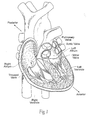
- the heart (see Fig. 1 ) is slightly larger than a clenched fist. It is a double (left and right side), self-adjusting muscular pump, the parts of which work in unison to propel blood to all parts of the body.
- the right side of the heart receives poorly oxygenated ("venous”) blood from the body from the superior vena cava and inferior vena cava and pumps it through the pulmonary artery to the lungs for oxygenation.
- the left side receives well-oxygenation (“arterial”) blood from the lungs through the pulmonary veins and pumps it into the aorta for distribution to the body.
- the heart has four chambers, two on each side -- the right and left atria, and the right and left ventricles.
- the atria are the blood-receiving chambers, which pump blood into the ventricles.
- a wall composed of membranous and muscular parts, called the interatrial septum, separates the right and left atria.
- the ventricles are the blood-discharging chambers.
- a wall composed of membranous and muscular parts, called the interventricular septum separates the right and left ventricles.
- the synchronous pumping actions of the left and right sides of the heart constitute the cardiac cycle.
- the cycle begins with a period of ventricular relaxation, called ventricular diastole.
- the cycle ends with a period of ventricular contraction, called ventricular systole.
- the heart has four valves (see Figs. 2 and 3 ) that ensure that blood does not flow in the wrong direction during the cardiac cycle; that is, to ensure that the blood does not back flow from the ventricles into the corresponding atria, or back flow from the arteries into the corresponding ventricles.
- the valve between the left atrium and the left ventricle is the mitral valve.
- the valve between the right atrium and the right ventricle is the tricuspid valve.
- the pulmonary valve is at the opening of the pulmonary artery.
- the aortic valve is at the opening of the aorta.
- ventricular diastole i.e., ventricular filling
- the aortic and pulmonary valves are closed to prevent back flow from the arteries into the ventricles.
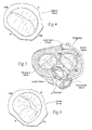
- the tricuspid and mitral valves open (as Fig. 2 shows), to allow flow from the atria into the corresponding ventricles.
- the tricuspid and mitral valves close (see Fig. 3 ) -- to prevent back flow from the ventricles into the corresponding atria -- and the aortic and pulmonary valves open -- to permit discharge of blood into the arteries from the corresponding ventricles.
- the opening and closing of heart valves occur primarily as a result of pressure differences.
- the opening and closing of the mitral valve occurs as a result of the pressure differences between the left atrium and the left ventricle.
- the mitral valve opens, allowing blood to enter the ventricle.
- the ventricle contracts during ventricular systole, the intraventricular pressure rises above the pressure in the atrium and pushes the mitral valve shut.
- the mitral and tricuspid valves are defined by fibrous rings of collagen, each called an annulus, which forms a part of the fibrous skeleton of the heart.
- the annulus provides attachments for the two cusps or leaflets of the mitral valve (called the anterior and posterior cusps) and the three cusps or leaflets of the tricuspid valve.
- the leaflets receive chordae tendineae from more than one papillary muscle. In a healthy heart, these muscles and their tendinous cords support the mitral and tricuspid valves, allowing the leaflets to resist the high pressure developed during contractions (pumping) of the left and right ventricles.
- chordae tendineae become taut, preventing the leaflets from being forced into the left or right atria and everted. Prolapse is a term used to describe this condition. This is normally prevented by contraction of the papillary muscles within the ventricle, which are connected to the mitral valve leaflets by the chordae tendineae. Contraction of the papillary muscles is simultaneous with the contraction of the ventricle and serves to keep healthy valve leaflets tightly shut at peak contraction pressures exerted by the ventricle.
- the dimensions of the mitral valve annulus create an anatomic shape and tension such that the leaflets coapt, forming a tight junction, at peak contraction pressures.
- the leaflets coapt at the opposing medial and lateral sides of the annulus are called the leaflet commissures, and are designated in Fig. 4 and in other Figures as CM (denoting the medial commissure) and CL (denoting the lateral commissure).
- Valve malfunction can result from the chordae tendineae (the chords) becoming stretched, and in some cases tearing. When a chord tears, the result is a leaflet that flails. Also, a normally structured valve may not function properly because of an enlargement of or shape change in the valve annulus. This condition is referred to as a dilation of the annulus and generally results from heart muscle failure. In addition, the valve may be defective at birth or because of an acquired disease.
- mitral valve dysfunction can occur when the leaflets do not coapt at peak contraction pressures.
- Fig. 5 shows, the coaptation line of the two leaflets is not tight at ventricular systole. As a result, an undesired back flow of blood from the left ventricle into the left atrium can occur. This condition is called regurgitation.
- the leaflets do not form a tight coaptation junction because the dimensions of the mitral valve annulus, measured along the major axis from commissure to commissure -- CM to CL -- and/or measured along the minor axis anterior to posterior -- A to Pchange. The changed dimensions no longer create the anatomic shape and tension in which the leaflets coapt at peak contraction pressures.
- the ratio between the commissure-to-commissure distance along the major axis and anterior-to-posterior distance along the minor axis bears a relationship to the effectiveness of leaflet coaptation. If the anterior-to-posterior distance along the minor axis increases, the ratio changes, and when the ratio reaches a certain value, regurgitation or the likelihood of regurgitation is indicated.
- Mitral valve regurgitation can be an acute or chronic condition. It is sometimes called mitral insufficiency.
- diuretics and/or vasodilators can be used to help reduce the amount of blood flowing back into the left atrium.
- An intra-aortic balloon counterpulsation device is used if the condition is not stabilized with medications.
- surgery to repair or replace the mitral valve is often necessary.
- annulus can be reshaped with annular or peri-annular rings or similar ring-like devices.
- the repair devices are typically secured to the annulus and surrounding tissue with suture-based fixation.
- the repair devices extend over the top and over much or all of the circumference of the annulus and leaflet surfaces.
- a physician may decide to replace an unhealthy mitral valve rather than repair it.
- Invasive, open heart surgical approaches are used to replace the natural valve with either a mechanical valve or biological tissue (bioprosthetic) taken from pigs, cows, or horses.
- an implant system according to claim 1.
- the invention provides systems that employ an implant sized and configured to attach, at least in part, in, on, or near the annulus of a dysfunctional heart valve.
- the implant extends either across the minor axis of the annulus to shorten the minor axis, or across the major axis of the annulus to lengthen the major axis, or both.
- the implant restores to the heart valve annulus and leaflets a more functional anatomic shape and tension. The more functional anatomic shape and tension are conducive to coaptation of the leaflets, which, in turn, reduces retrograde flow or regurgitation.
- the invention provides, a multi-function implant system to affect a shape of a heart valve annulus.
- the system comprises a first component that is sized and configured to engage and outwardly displace tissue along a major axis of the annulus.
- the system also includes a second component that is sized and configured, concurrent with the first component, to engage and inwardly displace tissue along a minor axis of the annulus.
- the first and second components can comprise separate components or form an integrated body. can occupy the same heart chamber, or the can occupy different heart chambers. In one arrangement, one of the magnetic components occupies a coronary sinus.
- the implant comprises a body sized and configured to rest near or within an annulus of a heart valve having leaflet commissures.
- the body includes spaced-apart struts that are appended to the body to contact tissue at or near the leaflet commissures.
- the struts include elastic jaws that exert pulling forces on tissue at or near the commissures to squeeze the annulus together at the commissures to promote leaflet coaptation.
- the body and/or the struts and/or the jaws can comprise wire-form structures. Desirable, the body, the struts, and the jaws are collapsible for placement within a catheter.
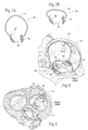
- Figs. 7A and 7B show embodiments of implants 10 sized and configured to rest at or near a heart valve annulus.
- the embodiment of the implant 10 of Fig. 7A is shown resting in a mitral valve.
- the implant 10 extends along the minor axis (i.e., across the valve annulus in an anterior-to-posterior direction).
- the implant 10 is sized and shaped so that, in use, it applies a direct mechanical force along the minor axis of the annulus.
- the direct mechanical force serves to inwardly displace tissue (i.e., to displace tissue toward the center of the annulus) to reshape the annulus.
- the mechanical force serves to shorten the minor axis of the annulus.
- the implant 10 can also reactively reshape the annulus along its major axis and/or reactively reshape other surrounding anatomic structures.
- the implant may only need to reshape the annulus during a portion of the heart cycle, such as during ventricular systolic contraction.
- the implant may be sized to produce small or negligible displacement of the annulus to restore or enhance inward movement of the annulus during ventricular diastolic contraction.
- the mechanical force applied by the implant 10 across the minor axis can restore to the heart valve annulus and leaflets a more normal anatomic shape and tension (see Figs. 8 and 9 ).
- the more normal anatomic shape and tension are conducive to coaptation of the leaflets during ventricular systole, which, in turn, reduces regurgitation.
- the implant 10 is made -- e.g., by bending, shaping, joining, machining, molding, or extrusion -- from a biocompatible metallic or polymer material, or a metallic or polymer material that is suitably coated, impregnated, or otherwise treated with a material to impart biocompatibility, or a combination of such materials.
- the material is also desirably radio-opaque or incorporates radio-opaque features to facilitate fluoroscopic visualization.
- the implant 10 includes a pair of struts 12 joined by an intermediate rail 14.
- the struts 12 are sized and configured to engage tissue at either an infra-annular position (i.e., engaging the fibrous body of the annulus) or a supra-annular position (i.e., engaging atrial tissue above or near the annulus).
- the rail 14 spans the struts 12.
- the rail 14 (like the struts 12) can take various shapes and have various cross-sectional geometries.
- the rail 14 (and/or the struts 12) can have, e.g., a generally curvilinear (i.e., round or oval) cross-section, or a generally rectilinear cross section (i.e., square or rectangular), or combinations thereof.
- the rail 14 of the implant 10 is configured to extend significantly above the plane of the valve toward the dome of the left atrium.
- the rail 14 of the implant 10 is configured to not extend significantly above the plane of the valve, but extend only enough to avoid interference with the valve leaflets.
- the struts 12 each include one or more fixation elements 16.
- a given fixation element 16 is sized and configured to take purchase in tissue in either the infra-annular or supra-annular position.
- the fixation element 16 desirably relies at least partly on the valve annulus and/or neighboring anatomic structures to anchor and fix the position of the implant and resist its migration out of the annulus.
- the fixation element 16 comprises an array of barbs that penetrate tissue.
- Figs. 12 and 13 show another representative embodiment for a fixation element 16, which comprises an array of tines that may contain secondary barbs in a direction that facilitates griping the tissue.
- Other types and forms of tissue fixation elements 16 can be used, e.g., pads with or without tissue penetrating members, and/or roughened surfaces and/or tissue in-growth promoting materials, such as polyester fabric. Any fixation element 16 may, if desired, be combined with suture, an adhesive, or like material to further secure the implant.
- the implant 10 Being free of an appendage that extends beneath the annulus, adjustment of implant position after or during implantation is facilitated.
- the implant 10 also presents less chance of trauma or damage to tissue and anatomic structures beneath the annulus.
- the implant 10 is "elastic."
- the rail 14 is sized and configured to possess a normal, unloaded, shape or condition (shown in Fig. 7 ). In this condition, the rail 14 is not in compression or tension, and the struts 12 are spaced apart closer than the anterior-to-posterior dimension of the minor axis of the targeted heart valve annulus.
- the material of the implant 10 is selected to possess a desired spring constant. The spring constant imparts to the rail 14 the ability to be elastically spread apart and placed in tension out of its normal, unloaded condition, in response to external stretching forces applied at the struts.
- the rail 14 assumes an elastically loaded, in-tension condition.
- the rail 14 exerts, through the struts 12 and fixation element 16, opposing pulling forces on tissues at or near the annulus. These forces are shown by arrows marked PF in Figs. 8 and 9 .
- the pulling forces inwardly displace tissue and shorten the annulus along its minor axis.
- the pulling forces can also reshape the major axis and/or surrounding anatomic structures. In this way, the implant 10 can reshape the valve annulus toward a shape more conducive to leaflet coaptation.
- An elastic implant as described can be made, e.g., from superelastic alloy, like Nitinol material.
- the implant can also be elastically straightened and/or folded to fit within a catheter or sheath during deployment, and will regain a preferred shape upon deployment.
- the spring constant of the implant 10 may be selected to be greater than the spring constant of adjoining tissue. Alternatively, the spring constant of the implant 10 may be selected to approximate the spring constant of adjoining tissue, thereby providing compliance to allow the implant 10 to adapt to tissue morphology during use.
- the spring constant of the implant 10 may vary along the length of the rail 14, so that some portions of the rail 14 are stiffer or more compliant than other portions of the rail 14.
- the implant 10 as just described and shown in either Fig. 7A or 7B lends itself to implantation in a heart valve annulus in various ways.
- the implant 10 can be implanted, e.g., in an open heart surgical procedure.
- the implant 10 can be implanted using catheter-based technology via a peripheral venous access site, such as in the femoral or jugular vein or femoral artery, under image guidance.
- the implant 10 can be implanted using thoracoscopic means through the chest, or by means of other surgical access through the right atrium, also under image guidance.
- Image guidance includes but is not limited to fluoroscopy, ultrasound, magnetic resonance, computed tomography, or combinations thereof.
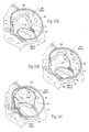
- Figs. 10 and 11 show a representative embodiment of the deployment of an elastic implant 10 of the type shown in Figs. 7A, 8, and 9 by a percutaneous, catheter-based procedure, under image guidance.
- Percutaneous vascular access is achieved by conventional methods into the femoral or jugular vein.
- a catheter 52 is steered through the vasculature into the right atrium.
- a needle cannula 54 carried on the distal end of the catheter is deployed to pierce the septum between the right and left atrium.
- a guide wire 56 is advanced trans-septally through the needle catheter 52 into the left atrium.
- the first catheter 52 is withdrawn (as Fig. 10C shows), and under image guidance, an implant delivery catheter 58 is advanced over the guide wire 56 into the left atrium into proximity with the mitral valve.
- the implant delivery catheter 58 can be deployed trans-septally by means of surgical access through the right atrium.
- the implant delivery catheter 58 carries a sheath 60 at its distal end (see Fig. 10C ).
- the implant 10 is constrained in a collapsed, straightened condition within the sheath.
- the sheath 60 is sized and configured to be withdrawn (e.g., by sliding it proximally), to progressively free the implant 10.
- the elastic implant 10 will expand and take shape.
- a flexible push rod in the catheter 58 can be used to expel the implant 10 from the sheath 60, with the same result.
- the struts 12 are folded within the sheath 60 to reduce the collapsed profile and facilitate the expansion of the implant 10 once free of the sheath 60.
- Fig. 11A shows, under image guidance, the strut 12 on the posterior end of the implant 10 is first freed from the sheath 60.
- the posterior strut 12 is manipulated to place the fixation element 16 into tissue in or near the posterior annulus.
- Fig. 11B shows, the delivery catheter 58 maintains force on the posterior strut 12, as the sheath 60 is further withdrawn, as the catheter tracks across the minor axis of the annulus in a posterior-to-anterior direction.
- the delivery catheter 58 may be sized and configured to have the column strength sufficient to maintain force on the posterior strut.
- the elastic implant 10 takes shape (see Fig. 11C ), until the anterior strut 12 unfolds.
- the rail 14 can be placed into tension, e.g., using a balloon B and/or catheter-deployed grasping instruments, to seat the fixation element 16 of the anterior strut 12 in tissue at or near the anterior annulus. Once seated, the strut 12 is released by the catheter 58.
- the implant 10 includes bell-shaped protrusions 20 and 22 formed, respectively, along anterior and posterior portions of the rail 14.
- the anterior protrusion 20 is sized and configured to, when implanted, extend through the septum and project into the right atrium. There, the anterior protrusion 20 is exposed for manipulation by a suitable grasping instrument deployed in the right atrium.
- the grasping instrument can take hold of the protrusion 20 in the right atrium to facilitate placement of the rail 14 in tension within the left atrium.
- the posterior protrusion 22 within the left atrium can also be grasped by an instrument in the left atrium, to aid in positioning and/or for tensioning the rail.
- barbed stays 24 braced against the septum can be crimped to the anterior protrusion 20, to help maintain a desired degree of tension on the rail 14 in the left atrium.
- the projection of the anterior protrusion 20 into the right atrium facilitates repositioning and/or retrieval of the implant 10 from the right atrium, when desired.
- Fig. 14 shows another embodiment of an implant 26, which is sized and configured to apply a mechanical force along the minor axis of a heart valve, or to otherwise stabilize tissue adjacent a heart valve annulus, and, in particular, a mitral heart valve annulus, as Figs. 15 and 16 show.
- the mechanical force that is applied by the implant 26 in Figs. 15 and 16 serves to inwardly displace tissue (i.e., to displace tissue toward the center of the annulus) (see Figs. 15 and 16 ), to shorten the minor axis and reshape the valve.
- the mechanical force directly applied by the implant 26 across the minor axis can also reactively reshape the major axis of the annulus as well as reshape other surrounding anatomic structures.
- the implant 26 can restore the heart valve annulus and leaflets to a more normal anatomic shape and tension conducive to coaptation of the leaflets during ventricular systole, which, in turn, reduces regurgitation. It should be appreciated, however, the presence of the implant 26 may serve to stabilize tissue adjacent the heart valve annulus, without affecting the length of the minor axis.
- the implant 26 is made -- e.g., by bending, shaping, joining, machining, molding, or extrusion -- from a biocompatible metallic or polymer material, or a metallic or polymer material that is suitably coated, impregnated, or otherwise treated with a material to impart biocompatibility, or a combination of such materials.
- the material is also desirably radio-opaque to facilitate fluoroscopic visualization.
- the implant 26 includes a pair of struts 28 and 30 joined by an intermediate rail 32.
- the rail 32 (like the struts 28 and 30) can take various shapes and have various cross-sectional geometries.
- the rail 32 (and/or the struts 28 and 30) can have, e.g., a generally curvilinear (i.e., round or oval) cross-section, or a generally rectilinear cross section (i.e., square or rectangular), or combinations thereof.
- the struts 28 and 30 at one or both ends of the rail 32 may include a fixation element 34 to enhance fixation in tissue.
- tissue fixation elements 34 can be used, e.g., tissue penetrating barbs (as shown), pads with roughened surfaces or tissue in-growth promoting materials, such as polyester fabric. Any fixation element 34 may, if desired, be combined with suture, an adhesive, or like material to further secure the implant.
- the fixation element 34 on the posterior strut 30 is sized and configured to engage tissue at either an infra-annular position (i.e., engaging the fibrous body of the annulus) or a supra-annular position (i.e., engaging atrial tissue) above or near the posterior annulus within the left atrium.
- the fixation element 34 on anterior strut 28 is sized and configured to pass through the septum and project into the right atrium. There, the fixation element 34 itself can engage tissue in the septum.
- the fixation element 34 can include an anchor button 36.
- the anchor button 36 captures the anterior strut 28 and holds the anterior strut 28 against the septum in the right atrium.
- the implant 26 can be deployed within a catheter 52 from the right atrium into the left atrium, in the same manner shown in Figs. 10A, 10B, and 10C .
- the fixation element 34 on the posterior strut 30 is positioned in engagement with tissue in either an infra-annular or supra-annular location the posterior annulus (as Fig. 17A shows), and the anterior strut 28 is lead through the septum (as Fig. 17B shows).
- Fig. 17B shows, pulling on the anterior strut 28 within the right atrium (i.e., through the septum) exerts a pulling force on tissue at or near the posterior annulus (shown by an arrow in Fig. 17B ).
- the pulling force draws the posterior annulus inwardly toward the anterior annulus, thereby shortening the annulus along its minor axis.
- the pulling forces can also reactively reshape the annulus along its major axis, as well as reshape surrounding anatomic structures. In this way, the implant reshapes the valve annulus toward a shape more conducive to leaflet coaptation, just as the implant 10 previously described.
- the fixation elements 34 on the posterior struts 30 take purchase in tissue within the left atrium in spaced-apart locations above or near or in the posterior annulus.
- the fixation elements 34 on the anterior struts 28 jointly pass through the septum. Pulling on the anterior struts 28 from within the right atrium draws the posterior annulus toward the anterior annulus, thereby shortening the annulus across its minor axis.
- the anterior struts 28 can be pulled individually or concurrently to achieve the reshaping desired.
- one implant 26 is shaped to direct force outward toward the septum wall of the left atrium, while the other implant 26 is shaped to direct force outward toward the lateral wall of the left atrium.
- the resulting forces are uniformly distributed along the posterior annulus.
- the anterior struts 28 can be jointly fixed against the septum by the anchor button 36.
- the fixation elements 34 themselves can apply the holding force, without use of the anchor button 36.
- Figs. 18A /B/C and 19A/B show various comparative magnetic force systems 62 that, in use, shorten an axis of a heart valve using one or more implanted magnetic elements 64.
- the implanted magnetic elements 64 generate magnetic field forces that attract tissue regions of the annulus toward one another.
- the tissue regions comprise the posterior and anterior edges of a mitral valve annulus.
- the magnetic field forces draw the tissue regions closer together across the minor axis of the annulus.
- the minor axis of the annulus is thereby shortened.
- shortening of the minor axis can reshape the valve, as well as reshape other surrounding anatomic structures, to restore the heart valve annulus and leaflets to a more normal anatomic shape and tension conducive to coaptation of the leaflets during ventricular systole, which, in turn, reduces regurgitation.
- the magnetic elements 64 comprise two or more permanent magnets 66.
- Permament magnets 66 can comprise, e.g., alloys of Neodymium-Iron-Boron (NdFeB), alloys of Aluminum-Nickel-Cobalt (AlNiCo), and Samarium Cobalt (SmCo).
- a permanent magnet 66 generates an external magnetic field.
- two permanent magnets 66A and 66B are affixed on or above the annulus in the left atrium, with opposite magnetic poles facing each other (North-South or South-North). Poles of opposite polarity attract each other with a magnetic force. The force of magnetic attraction depends on the strength of the magnets and the distance between them.
- FIGs. 18A and 18B two permanent magnets 66A and 66B of opposite polarity are affixed, respectively, on or above the anterior and posterior regions of the annulus, aligned generally across the minor axis of the annulus.
- the force of magnetic attraction (shown by arrows) draws the posterior annulus and the anterior annulus toward one another, shortening the minor axis (see Fig. 18C also).
- At least one additional permanent magnet 66C is provided on or above the posterior annulus on one or both sides of the magnet aligned on the minor axis.
- the additional permanent magnet 66C has a pole facing the adjacent minor axis magnet 66A that is like the pole of the adjacent minor axis magnet. Poles of like polarity repel each other with a magnetic force. The force of magnetic repulsion pushes the additional permanent magnet 66C and the adjacent minor axis magnet 66A apart, keeping the two magnets 66A and 66C on the posterior annulus apart and stretching tissue between the magnets 66A and 66C.
- the force of magnetic attraction between the permanent magnets 66A and 66C on the posterior annulus and the anterior annulus 66B is amplified, further enhancing the force that draws the posterior annulus and the anterior annulus toward one another, shortening the minor axis.
- a permanent magnet 66D is affixed on or above either the anterior annulus or the posterior annulus generally aligned with the minor axis.
- the permanent magnet 66D is shown affixed on or above the anterior annulus.
- an array of soft ferromagnetic materials 68 e.g. Iron (Fe) is affixed.
- Soft magnetic materials 68 are attracted by a permanent magnet 66D.
- the force of magnetic attraction draws the posterior annulus and the anterior annulus toward one another, shortening the minor axis.
- the force of attraction can be strengthened (see Fig. 19B ) by affixing an additional permanent magnet 66E on or above the anterior annulus adjacent the minor axis permanent magnet 66D.
- the additional permanent magnet 66E has a pole facing the adjacent minor axis magnet that is like the pole of the adjacent minor axis magnet 66D.
- the force of magnetic repulsion pushes the additional permanent magnet and minor axis magnet apart, keeping the two magnets on the anterior annulus spaced apart and stretching tissue between the two magnets 66D and 66E.
- two or more permanent magnets 66F and 66G having opposite magnetic poles can be affixed on or above given regions of the annulus (here, the anterior annulus), without companion, oppositely spaced magnets.
- the force of magnetic attraction draws the permanent magnets together, stretching the tissue along the circumference of the posterior annulus.
- the magnetic force field reshaping occasioned in this arrangement shortens the minor axis, reshaping the annulus.
- the permanent magnets 66 and/or soft ferromagnetic materials 68 can be machined, laser cut, chemically etched, or EDM manufactured into packets 70 of various shapes.
- the packets 70 are desirably encased or packaged in an inert, insulation material, such as gold.
- the packets include one or more fixation elements 72, which anchor the packets 70 in tissue on or above the targeted valve annulus.
- the packets 70 are button-shaped, and the fixation elements 72 comprise barbs that penetrate tissue.
- Other shapes and configuration can, of course, be used.
- the packet 70 is button-shaped and further includes a leaflet retaining appendage 76.
- the leaflet retaining appendage 76 When anchored into tissue on or above an annulus (see Fig. 24 ), the leaflet retaining appendage 76 overlays at least a portion of one or more native valve leaflets.
- the leaflet retaining appendage 76 resists leaflet eversion and/or prolapse. In this way, a system of magnetic implants not only reshapes the valve annulus along the minor axis, but also prevents or reduces retrograde flow and regurgitation.
- the leaflet retaining appendage 76 does not interfere with the opening of and blood flow through the leaflets during antegrade flow.
- Fig. 25 shows another comparative magnetic force system 78 that, in use, shortens an axis of a heart valve using one or more implanted magnets 80 and 82.
- the magnets 80 and 82 are not anchored on or above the annulus within the heart chamber occupied by the heart valve. Instead, the magnets 80 and 82 are placed outside the heart chamber to generate magnetic field forces that attract tissue regions of the annulus toward one another.
- the heart valve comprises the mitral valve in the left atrium.
- a permanent magnet 80 is implanted either in the coronary sinus near the posterior annulus or on the septum in the right atrium close to the anterior annulus.
- the permanent magnet 80 is shown implanted in the coronary sinus.
- a second magnetic element 82 is implanted in the other location -- here, on the septum in the right atrium close to the anterior annulus.
- the second magnetic element 82 can comprise a permanent magnet having a polarity opposite to the polarity of the first permanent magnet, or it can comprise a soft ferromagnetic material. The force of magnetic attraction between the permanent magnet 80 and the second magnetic element 82 draws the posterior annulus and the anterior annulus toward one another, shortening the minor axis.
- Magnetic force systems 62 or 78 that shorten an axis of a heart valve can be deployed during an open surgical or thoracoscopic procedure. Alternatively, catheter-based approaches may also be used.
- a given minor axis implant 84 is used in combination with a major axis implant 86, forming a combined implant system 88.
- the major axis implant 86 provides direct lengthening along the major axis of the annulus.
- the active lengthening of the major axis (by the major axis implant 86) is accompanied by the active shortening of the minor axis (by the minor axis implant 84).
- Use of the major axis implant 86 complements the minor axis implant 84, enhancing the reactive lengthening of the major axis occasioned by use of the minor axis implant 84.
- the major axis implant 86 can be sized and configured to achieve other objectives.
- the major axis implant 86 can, for example, be sized and configured to shorten the major axis.
- the major axis implant 86 can be sized and configured to merely stabilize tissue adjacent the heart valve annulus, without attendant lengthening or shortening of the major axis.
- a major axis implant 86 of these alternative sizes and configurations can be used alone or in combination with a minor axis implant.
- the major axis implant 86 is sized and configured as a single function component to rest along the major axis of the annulus above and/or along the valve annulus, in combination with a single function minor axis implant 84.
- the major axis implant 86 can be of the type described in US 2004/0127982, filed October 1, 2003 , and entitled "Devices, Systems, and Methods for Reshaping a Heart Valve Annulus.”
- the major axis implant 86 is desirably made -- e.g., by bending, shaping, joining, machining, molding, or extrusion -- from a biocompatible, super-elastic metallic material.
- the major axis implant 86 includes a pair of struts 90 joined by an intermediate rail 92.
- the struts 90 of the major axis implant 86 are sized and configured to rest in, at, or near the leaflet commissures.
- the superelastic material of the implant 86 is selected to possess a desired spring constant, which imparts to the rail 92 the ability to be elastically compressed into an elastically loaded condition resting in engagement with tissue in, at, or near the leaflet commissures.
- the rail 92 exerts opposing forces to the tissues in, at, or near the commissures through the struts 90, tending to outwardly displace tissue and stretch the annulus along its major axis.
- Figs. 29 and 30 show another representative example of a single function major axis implant 86.
- the major axis implant 86 is shown alone in Figs. 29 and 30 show) and in association with a single function minor axis implant 84 to form a system 88 of the type shown in Figs. 26 and 27 .
- the implant 86 includes two rails 92 forming a closed rail structure.
- the rails 92 are supported by legs 134.
- the legs 134 are generally spaced 180° apart. In use (see Fig. 30 ), the implant 86 resides in the atrium above the mitral valve.
- the depending base of each leg 134 carries a fixation element 136.
- the fixation element 136 takes purchase in atrial tissue above and near to the commissures along the major axis of the annulus.
- the spring force of the legs 134 and rails 92 apply a spreading force that stretches tissue along the major axis.
- the high rails 92 protects against spreading of the leaflets.
- the fixation element 136 comprises a pad of barbs that penetrate atrial tissue above the annulus.
- tissue engaging mechanisms e.g., roughened surfaces or tissue in-growth promoting materials. Placing numerous fixation elements 136 on legs 134 that engage tissue above the annulus makes it possible to reduce the force applied per unit of tissue area. Any fixation element 146 may, if desired, be combined with suture, an adhesive, or like material to further secure the implant.
- Major axis implants 86 like that shown in Figs. 29 and 30 can be located without the need to identify the exact position of the commissures. Adjustment of implant position after or during implantation is also facilitated, as there is no need to remove a strut from a commissure. Implants 86 like that shown in Figs. 29 and 30 also present less chance of trauma or damage to tissue and anatomic structures beneath the annulus.
- a multi-function implant 138 can be sized and configured to rest about the annulus (as Fig. 32 shows) and function to reshape both major and minor axes.
- the multi-function implant 138 is desirably made -- e.g., by bending, shaping, joining, machining, molding, or extrusion -- from a biocompatible, super-elastic metallic material. As shown in Fig. 31 , the implant 138 includes a pair of struts 140 joined by a pair of oppositely spaced rails 142 and 144, forming a ring-like structure.
- the rails 142 and 144 can take various shapes.
- the struts 140 of the implant 138 are sized and configured to rest in, at, or near the leaflet commissures.
- the superelastic material of the implant 138 is selected to possess a desired spring constant, which imparts to the rails 142 and 144 the ability to be elastically compressed into an elastically loaded condition resting in engagement with tissue in, at, or near the leaflet commissures.
- the rails 142 and 144 exert opposing forces to the tissues in, at, or near the commissures through the struts 140, tending to outwardly displace tissue and providing the function of stretching the annulus along its major axis.
- the struts 140 can comprise the legs and fixation elements shown in Figs. 29 and 30 , or other forms of tissue fixation mechanisms, to accommodate purchase in atrial tissue above the annulus, to perform the same function.
- the rails 142 and 144 include fixation elements 146, which, in the illustrated arrangement, take the form of tissue penetrating barbs.
- the fixation elements 146 on the rails 142 and 144 are sized and configured to take purchase in tissue in either annuluar, infra-annuluar or supra-annular tissue adjacent to, respectively, the anterior annulus and the posterior annulus (as Fig. 32 shows).
- the superelastic material of the implant 138 is selected to possess a desired spring constant, which imparts to the rails 142 and 144 the ability to be elastically stretched and placed into tension when resting in engagement with tissue adjacent the anterior annulus and posterior annulus.
- the rails 142 and 144 When in the elastically loaded, in-tension condition, the rails 142 and 144 exert opposing pulling forces on tissue at or near the annulus. This provides the function of shortening the annulus along its minor axis.
- the rails 142 and 144 can be expanded apart, e.g., by use of a balloon 148 placed between the rails 142 and 144 and inflated, placing the fixation elements 146 into contact with tissue. Collapsing the balloon allows the implant to assume its desired shape with the tissue attached.
- tissue fixation elements 146 can comprise barbs that are deployed in an inwardly folded condition.
- the barbs 146 can be outwardly folded when the rails 142 and 144 are expanded apart, e.g., by use of a balloon 148 placed between the rails 142 and 144 and inflated (see Fig. 34 ).
- the balloon 148 Upon further inflation of the balloon 148 (see Figs. 35 and 36 ), the barbs 146 are driven into either infra-annuluar or supra-annular tissue adjacent to the anterior annulus and the posterior annulus (as Fig. 37 shows).
- the balloon 148 also places the rails 142 and 144 into tension, to perform their intended function of shortening the minor axis of the annulus.
- the tissue fixation elements 146 can take the form of pads with or without tissue penetrating members, and/or roughened surfaces and/or tissue in-growth promoting materials, such as polyester fabric. Any fixation element 146 may, if desired, be combined with suture, an adhesive, or like material to further secure the implant 138.
- any of the single function implants 86 or multiple function implants 138 can be elastically straightened and/or folded to fit within a catheter or sheath for deployment, as generally shown in Fig. 10C .
- the single function implants 86 or multiple function implants 138 can be deployed during an open surgical or thoracoscopic procedure.
- major axis implant 86 access into the left atrium through the septum from the right atrium can be accomplished as shown in Figs. 10A, 10B, and 10C .
- the implant delivery catheter 58 carries the major axis implant 86 in a sheath 60 at its distal end (see Fig. 38A ), in a collapsed, straightened condition.
- Fig. 38A shows, under image guidance, the strut 90 on the leading end of the major axis implant 86 is freed from the sheath 60 and seated retrograde in the medial commissure of the valve annulus.
- the sheath 60 is withdrawn in line with the coaptation line in a lateral direction along the coaptation line.
- the major axis implant 86 shapes and seats (as Figs. 38B and 38C show), until the trailing strut 90 unfolds and seats within the lateral commissure.
- the implant 86 can also be positioned or repositioned under image guidance within the left atrium using a catheter-deployed grasping instrument.
- the major axis implant 86 can include bell-shaped protrusions 94 and 96 formed along medial and lateral portions of the rail 92.
- the medial protrusion 94 is sized and configured to extend through the septum and project into the right atrium. There, the medial protrusion 94 is exposed for engagement by a grasping instrument deployed in the right atrium. The grasping instrument in the right atrium can take hold of the protrusion 94 to facilitate placement of the rail 92 in compression within the left atrium. Barbed stays 98 can be crimped to the medial protrusion 94 to help maintaining compression on the rail 92.
- the medial grasping site projects into the right atrium, also facilitates repositioning and/or retrieval of the major axis implant 86.
- the lateral protrusion 96 can likewise be grasped by an instrument in the left atrium for placing the rail 92 in compression.
- both the minor axis implant 84 and the major axis implant 86 can include grasping protrusions 100 and 102 that jointly project through the septum into the right atrium. Both protrusions 100 and 102 can be manipulated to place the minor axis implant 84 into tension and to place the major axis implant 86 into compression, as previously described, to achieve the desired reshaping of the annulus.
- Fig. 42 shows a comparative system 104 that includes an elastic component 106, to provide direct reshaping along one axis of a valve annulus, and a magnetic force field component 108, to provide direct reshaping along another axis of the valve annulus.
- the valve to be reshaped is the mitral valve in the left atrium.
- the elastic component 106 comprises an elastic major axis implant of the type already described (e.g., as shown in Figs. 30 or 39 ), which is sized and configured to rest along the major axis of the annulus above and/or along the valve annulus. As previously described, the elastic major axis implant 106 stretches the annulus along the major axis.
- the magnetic force field component 108 comprises magnetic elements 132 of the type previously described (e.g., as shown in Figs. 21A to 21E ).
- the magnetic elements 132 are located in a spaced-apart relationship across the minor axis on or above the anterior annulus and the posterior annulus.
- the magnetic elements 132 can comprise two permanent magnets of opposite polarity, or one permanent magnet and one soft ferromagnetic material.
- the magnetic elements 132 are stabilized at opposite ends of a yoke 110 coupled to the elastic major axis implant 106 near one of its struts.
- the magnetic elements 132 are implanted in tissue on or above the annulus. The force of magnetic attraction between the magnet components 132 draws the posterior annulus and the anterior annulus toward one another, shortening the minor axis.
- the yoke 110 supporting the magnetic elements 132 may possess a spring constant. Placing the yoke 110 into tension at the time the magnetic elements 132 are implanted on or above the annulus provides an auxiliary mechanical force, to augment the magnetic force serving to shorten the minor axis.
- Fig. 43 shows a point loaded annuloplasty system 112 for reshaping a heart valve annulus.
- the system 112 applies a mechanical force about the perimeter of the heart valve annulus.
- the mechanical force pulls on the annulus to restore a generally oval shape conducive to leaflet coaptation.
- Fig. 43 shows the heart valve annulus as comprising the mitral valve in the left atrium.
- the system 112 creates the mechanical force by circumferentially linking adjacent sites on or above the annulus with a biocompatible elastic frame 114.
- the frame 114 comprises an elastic material, such as SelasticTM material.
- the frame 114 links the sites by threading through a network of fasteners 116 that are inserted into tissue on or above the annulus.
- Figs. 44A to 44C show representative embodiments of the fasteners 116, which include clip components 118 to accommodate passage of the frame 114 and barbs 120 that secure the clip components 118 to tissue.
- the elastic frame 114 is in tension within the network of fasteners 116. The tension applied by the frame 114 pulls tissue in or along the annulus together, thereby tightening the annulus to restore a non-dilated shape.
- FIG.45 An alternative arrangement of a point loading annuloplasty system 122 is shown in Fig.45 .
- Fig.45 as in Fig.43 , an elastic frame 114 is placed into tension through a network of fasteners 116 that are inserted into tissue on or above the annulus.
- all of the fasteners 116 were located in or along the annulus.
- one fastener 116' is located in the right atrium outside the left atrium. The fastener 116' engages the septum.
- the frame 114 passes through the septum, pulling laterally on the septum toward the left atrium to reshape tissue along the anterior annulus.
- Fig. 46 shows an implant 124 for performing commissural annuloplasty.
- the implant 124 is sized and configured, in use, to rest along the major axis of a heart valve annulus above and/or along the valve annulus. In the illustrated embodiment (see Fig.47 ), the implant 124 rests along the major axis of a mitral valve annulus in the left atrium.
- the implant 124 is desirably made -- e.g., by bending, shaping, joining, machining, molding, or extrusion -- from a biocompatible metallic or plastic material. As shown in Fig. 39 , the implant 124 includes a pair of struts 126 joined by an intermediate rail 128.
- the struts 126 are sized and configured to rest in either an infra-annular or a supra-annular position at or near the annulus adjacent the medial and lateral leaflet commissures.
- the implant 124 includes a jaw 130 that is appended to each strut 126.
- the jaws 130 are made from an elastic material.
- Each jaw 130 is sized and configured to possess a normal, unloaded, shape or condition (shown in Fig.46 ). In this condition, the jaw 130 is not in compression or tension.
- the material of each jaw 130 is selected to possess a desired spring constant. The spring constant imparts to each jaw 130 the ability to be elastically spread apart (see Fig. 48A ) and placed in tension out of its normal, unloaded condition, in response to external stretching forces applied to the jaws 130.
- the jaws 130 When the jaws 130 are anchored in tissue in a stretched apart condition at or near the commissures (see Figs. 48A and 48B ), the jaws 130 assumes an elastically loaded, in-tension condition. When in this elastically loaded, in-tension condition, the jaws 130 exert opposing pulling forces on tissues at or near the commissures. These forces are shown by arrows in Fig. 48B . The pulling forces inwardly displace tissue at the commissures, squeezing the annulus together at the commissures to promote leaflet coaptation.
- the implant 124 can rest as shown in Fig. 47 without being in compression and/or tension, thereby itself applying no pushing or pulling force upon tissue along either the major or minor axes of the annulus.
- the implant 124 can be made of an elastic material. This imparts to the rail 128 the ability to be compressed into an elastically loaded condition resting in engagement with tissue in, at, or near the leaflet commissures. When in this condition, the rail 128 can exert opposing forces to the tissues in, at, or near the commissures through the struts 126, tending to outwardly displace tissue and stretch the annulus along its major axis.
- one or both of the jaws 130 of the implant 124 can be lengthened and shaped to follow the medial and lateral contours of the annulus, terminating in an oppositely facing relationship on the anterior annulus and posterior annulus, similar to the yoke 110 shown in Fig.42 .
- the jaws 130 possess a spring constant. Placing the jaws 130 in tension across the minor axis of the annulus (as Fig. 49 shows) at the time of implantation provides a mechanical force that shortens the minor axis, in the manner previously described.
- the jaws 130 can be further lengthened and shaped to form a full ring-like structure.
- the implant 124 can be used in association with a magnetic force field component 132 of the type previously described (e.g., as shown in Figs. 21A to 21E ).
- the magnetic components 132 are located in a spaced-apart relationship across the minor axis on or above the anterior annulus and the posterior annulus.
- the magnetic components 132 can comprise two permanent magnets of opposite polarity, or one permanent magnet and one soft ferromagnetic material.
- the magnetic components 132 are implanted in tissue on or above the annulus. The force of magnetic attraction between the magnet components 132 draws the posterior annulus and the anterior annulus toward one another, shortening the minor axis.
Description
- The invention is directed to systems for improving the function of a heart valve, e.g., in the treatment of mitral valve regurgitation.
- The heart (see
Fig. 1 ) is slightly larger than a clenched fist. It is a double (left and right side), self-adjusting muscular pump, the parts of which work in unison to propel blood to all parts of the body. The right side of the heart receives poorly oxygenated ("venous") blood from the body from the superior vena cava and inferior vena cava and pumps it through the pulmonary artery to the lungs for oxygenation. The left side receives well-oxygenation ("arterial") blood from the lungs through the pulmonary veins and pumps it into the aorta for distribution to the body. - The heart has four chambers, two on each side -- the right and left atria, and the right and left ventricles. The atria are the blood-receiving chambers, which pump blood into the ventricles. A wall composed of membranous and muscular parts, called the interatrial septum, separates the right and left atria. The ventricles are the blood-discharging chambers. A wall composed of membranous and muscular parts, called the interventricular septum separates the right and left ventricles.
- The synchronous pumping actions of the left and right sides of the heart constitute the cardiac cycle. The cycle begins with a period of ventricular relaxation, called ventricular diastole. The cycle ends with a period of ventricular contraction, called ventricular systole.
- The heart has four valves (see
Figs. 2 and 3 ) that ensure that blood does not flow in the wrong direction during the cardiac cycle; that is, to ensure that the blood does not back flow from the ventricles into the corresponding atria, or back flow from the arteries into the corresponding ventricles. The valve between the left atrium and the left ventricle is the mitral valve. The valve between the right atrium and the right ventricle is the tricuspid valve. The pulmonary valve is at the opening of the pulmonary artery. The aortic valve is at the opening of the aorta. - At the beginning of ventricular diastole (i.e., ventricular filling) (see
Fig. 2 ), the aortic and pulmonary valves are closed to prevent back flow from the arteries into the ventricles. Shortly thereafter, the tricuspid and mitral valves open (asFig. 2 shows), to allow flow from the atria into the corresponding ventricles. Shortly after ventricular systole (i.e., ventricular emptying) begins, the tricuspid and mitral valves close (seeFig. 3 ) -- to prevent back flow from the ventricles into the corresponding atria -- and the aortic and pulmonary valves open -- to permit discharge of blood into the arteries from the corresponding ventricles. - The opening and closing of heart valves occur primarily as a result of pressure differences. For example, the opening and closing of the mitral valve occurs as a result of the pressure differences between the left atrium and the left ventricle. During ventricular diastole, when ventricles are relaxed, the venous return of blood from the pulmonary veins into the left atrium causes the pressure in the atrium to exceed that in the ventricle. As a result, the mitral valve opens, allowing blood to enter the ventricle. As the ventricle contracts during ventricular systole, the intraventricular pressure rises above the pressure in the atrium and pushes the mitral valve shut.
- The mitral and tricuspid valves are defined by fibrous rings of collagen, each called an annulus, which forms a part of the fibrous skeleton of the heart. The annulus provides attachments for the two cusps or leaflets of the mitral valve (called the anterior and posterior cusps) and the three cusps or leaflets of the tricuspid valve. The leaflets receive chordae tendineae from more than one papillary muscle. In a healthy heart, these muscles and their tendinous cords support the mitral and tricuspid valves, allowing the leaflets to resist the high pressure developed during contractions (pumping) of the left and right ventricles.
- In a healthy heart, the chordae tendineae become taut, preventing the leaflets from being forced into the left or right atria and everted. Prolapse is a term used to describe this condition. This is normally prevented by contraction of the papillary muscles within the ventricle, which are connected to the mitral valve leaflets by the chordae tendineae. Contraction of the papillary muscles is simultaneous with the contraction of the ventricle and serves to keep healthy valve leaflets tightly shut at peak contraction pressures exerted by the ventricle.
- In a healthy heart (see
Fig. 4 ), the dimensions of the mitral valve annulus create an anatomic shape and tension such that the leaflets coapt, forming a tight junction, at peak contraction pressures. Where the leaflets coapt at the opposing medial and lateral sides of the annulus are called the leaflet commissures, and are designated inFig. 4 and in other Figures as CM (denoting the medial commissure) and CL (denoting the lateral commissure). - Valve malfunction can result from the chordae tendineae (the chords) becoming stretched, and in some cases tearing. When a chord tears, the result is a leaflet that flails. Also, a normally structured valve may not function properly because of an enlargement of or shape change in the valve annulus. This condition is referred to as a dilation of the annulus and generally results from heart muscle failure. In addition, the valve may be defective at birth or because of an acquired disease.
- Regardless of the cause (see
Fig. 5 ), mitral valve dysfunction can occur when the leaflets do not coapt at peak contraction pressures. AsFig. 5 shows, the coaptation line of the two leaflets is not tight at ventricular systole. As a result, an undesired back flow of blood from the left ventricle into the left atrium can occur. This condition is called regurgitation. - In some cases (see
Fig. 6 ), the leaflets do not form a tight coaptation junction because the dimensions of the mitral valve annulus, measured along the major axis from commissure to commissure -- CM to CL -- and/or measured along the minor axis anterior to posterior -- A to Pchange. The changed dimensions no longer create the anatomic shape and tension in which the leaflets coapt at peak contraction pressures. - Comparing a healthy annulus in
Fig. 4 to an unhealthy annulus inFig. 6 , the unhealthy annulus is dilated and, in particular, the anterior-to-posterior distance along the minor axis is increased. As a result, the shape and tension defined by the annulus becomes less oval (seeFig. 4 ) and more round (seeFig. 6 ). This condition is called dilation. When the annulus is dilated, the shape and tension conducive for coaptation at peak contraction pressures progressively deteriorate. Instead, at peak contraction pressures, the leaflets do not coapt completely, and a gap forms between the leaflets. During ventricular systole, regurgitation can occur through this gap. It is believed that the ratio between the commissure-to-commissure distance along the major axis and anterior-to-posterior distance along the minor axis bears a relationship to the effectiveness of leaflet coaptation. If the anterior-to-posterior distance along the minor axis increases, the ratio changes, and when the ratio reaches a certain value, regurgitation or the likelihood of regurgitation is indicated. - As a result of regurgitation, "extra" blood back flows into the left atrium. During subsequent ventricular diastole (when the heart relaxes), this "extra" blood returns to the left ventricle, creating a volume overload, i.e., too much blood in the left ventricle. During subsequent ventricular systole (when the heart contracts), there is more blood in the ventricle than expected. This means that: (1) the heart must pump harder to move the extra blood; (2) too little blood may move from the heart to the rest of the body; and (3) over time, the left ventricle may begin to stretch and enlarge to accommodate the larger volume of blood, and the left ventricle may become weaker.
- Although mild cases of mitral valve regurgitation result in few problems, more severe and chronic cases eventually weaken the heart and can result in heart failure. Mitral valve regurgitation can be an acute or chronic condition. It is sometimes called mitral insufficiency.
- In the treatment of mitral valve regurgitation, diuretics and/or vasodilators can be used to help reduce the amount of blood flowing back into the left atrium. An intra-aortic balloon counterpulsation device is used if the condition is not stabilized with medications. For chronic or acute mitral valve regurgitation, surgery to repair or replace the mitral valve is often necessary.
- To date, invasive, open heart surgical approaches have been used to repair mitral valve dysfunction. During these surgical repair procedures, efforts are made to cinch or resect portions and/or fix in position large portions of the dilated annulus. During these surgical repair procedures, the annulus can be reshaped with annular or peri-annular rings or similar ring-like devices. The repair devices are typically secured to the annulus and surrounding tissue with suture-based fixation. The repair devices extend over the top and over much or all of the circumference of the annulus and leaflet surfaces.
- A physician may decide to replace an unhealthy mitral valve rather than repair it. Invasive, open heart surgical approaches are used to replace the natural valve with either a mechanical valve or biological tissue (bioprosthetic) taken from pigs, cows, or horses.
- The need remains for simple, cost-effective, and less invasive devices, systems, and methods for treating dysfunction of a heart valve, e.g., in the treatment of mitral valve regurgitation.
- According to the present invention there is provided an implant system according to
claim 1. The invention provides systems that employ an implant sized and configured to attach, at least in part, in, on, or near the annulus of a dysfunctional heart valve. In use, the implant extends either across the minor axis of the annulus to shorten the minor axis, or across the major axis of the annulus to lengthen the major axis, or both. The implant restores to the heart valve annulus and leaflets a more functional anatomic shape and tension. The more functional anatomic shape and tension are conducive to coaptation of the leaflets, which, in turn, reduces retrograde flow or regurgitation. - The invention provides, a multi-function implant system to affect a shape of a heart valve annulus. The system comprises a first component that is sized and configured to engage and outwardly displace tissue along a major axis of the annulus. The system also includes a second component that is sized and configured, concurrent with the first component, to engage and inwardly displace tissue along a minor axis of the annulus. The first and second components can comprise separate components or form an integrated body. can occupy the same heart chamber, or the can occupy different heart chambers. In one arrangement, one of the magnetic components occupies a coronary sinus.
- One embodiment of the invention provides an implant that performs commissural annuloplasty. The implant comprises a body sized and configured to rest near or within an annulus of a heart valve having leaflet commissures. The body includes spaced-apart struts that are appended to the body to contact tissue at or near the leaflet commissures. The struts include elastic jaws that exert pulling forces on tissue at or near the commissures to squeeze the annulus together at the commissures to promote leaflet coaptation. The body and/or the struts and/or the jaws can comprise wire-form structures. Desirable, the body, the struts, and the jaws are collapsible for placement within a catheter.
- Other features and advantages of the invention shall be apparent based upon the accompanying description, drawings, and claims.
-
-
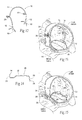
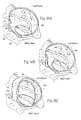
Fig. 1 is a perspective, anterior anatomic view of the interior of a healthy heart. -
Fig.2 is a superior anatomic view of the interior of a healthy heart, with the atria removed, showing the condition of the heart valves during ventricular diastole. -
Fig.3 is a superior anatomic view of the interior of a healthy heart, with the atria removed, showing the condition of the heart valves during ventricular systole. -
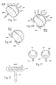
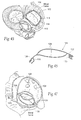
Fig. 4 is a superior anatomic view of a healthy mitral valve during ventricular systole, showing the leaflets properly coapting. -
Fig. 5 is a superior anatomic view of the interior of a heart, with the atria removed, showing the condition of the heart valves during ventricular systole, and further showing a dysfunctional mitral valve in which the leaflets are not properly coapting, causing regurgitation. -
Fig. 6 is a superior anatomic view of a disfunctional mitral valve during ventricular systole, showing that the leaflets are not properly coapting, causing regurgitation. -
Figs. 7A and 7B are side perspective views of implants sized and configured to rest at or near a heart valve annulus and apply a direct mechanical force along the minor axis of the annulus to inwardly displace tissue toward the center of the annulus, the implant shown inFig. 7A being configured to extend significantly above the plane of the valve, and the implant shown inFig. 7B being configured to extend a short distance above the plane of the valve. -
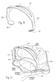
Fig. 8 is a lateral perspective view of the implant shown inFig. 7A deployed at or near the mitral valve annulus in the left atrium. -
Fig. 9 is a superior view of the implant and heart shown inFig. 8 . -
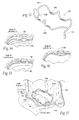
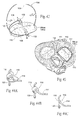
Figs. 10A. 10B, and 10C are perspective anterior views of the intravascular deployment of a catheter from the right atrium across the septum into the left atrium for the purpose of implanting an implant of the type shown inFig. 7A . -
Figs. 11A, 11B, and 11C are lateral perspective views of the sequential deployment of the implant shown inFig. 7A from the catheter shown inFigs. 10A, 10B, and 10C in the left atrium, with a balloon being shown inFig. 11C inflated to place the implant into tension across the minor axis of the mitral valve. -
Fig. 12 is a side perspective view of an alternative embodiment of an implant sized and configured to rest at or near a heart valve annulus and apply a direct mechanical force along the minor axis of the annulus to inwardly displace tissue toward the center of the annulus, the implant shown inFig. 12 including bell-shaped protrusions that can be grasped to aid in the positioning and/or tensioning of the implant. -
Fig. 13 is a lateral perspective view of the implant shown inFig. 12 deployed at or near the mitral valve annulus in the left atrium, with one of the bell-shaped protrusions extending through and anchored to the septum in the right atrium. -
Fig. 14 is a side view of an alternative embodiment of an implant sized and configured to rest at or near a heart valve annulus and apply a direct mechanical force along the minor axis of the annulus to inwardly displace tissue toward the center of the annulus, the implant shown inFig. 14 having an anterior component that is sized and configured to pass through the septum and project into the right atrium. -
Fig. 15 is a lateral perspective view of a pair of the implants shown inFig. 14 deployed at or near the mitral valve annulus in the left atrium, with the anterior component extending through and anchored to the septem in the right atrium. -
Fig. 16 is a superior view of the implants and the heart shown inFig. 15 . -
Figs. 17A and 17B are lateral side views of the deployment of one of the implants shown inFigs. 15 and16 from the right atrium and through the septum into the left atrium. -
Figs. 18A and 18B are superior views of a mitral valve annulus having different comparative magnetic force systems implanted at or near the annulus, to generate a magnetic field that attract tissue regions of the annulus toward one another, the magnetic force systems being arranged to shorten the minor axis of the annulus. -
Fig. 18C is an anterior side view of the magnetic force systems shown inFigs. 18A and 18B . -
Figs. 19A and 19B are superior views of a mitral valve annulus with further comparative magnetic force systems of the types shown inFigs, 18A, 18B, and 18C implanted at or near the annulus, to generate a magnetic field that attract tissue regions of the annulus toward one another to shorten the minor axis of the annulus. -
Fig. 20 is a superior view of a mitral valve annulus with another comparative magnetic force system implanted at or near the annulus along one side of the annulus, to generate a magnetic field that attract tissue regions along that side of the annulus toward one another. -
Fig. 21 is a representative arrangement of comparative button-shaped magnetic elements that can be used to create the magnetic force systems shown inFigs. 18A, 18B, 18C ,19A, 19B, and 20 . -
Fig. 22 is a side section view of a button-shaped magnetic element taken generally along line 22-22 isFig. 21 . -
Figs. 23A and 23B shown a comparative button-shaped magnetic element that can be used to create the magnetic force systems shown inFigs. 18A, 18B, 18C ,19A, 19B, and 20 , the magnetic element including a leaflet retaining appendage that overlays a native valve leaflet,Fig. 23A being a side perspective view andFig. 23B being a side section view of the magnetic element and appendage. -
Fig. 24 is a superior view of a mitral valve with the magnetic elements shown inFigs. 23A and 23B implanted along opposite anterior and posterior sides of the annulus. -
Fig. 25 is a superior view of a heart showing the presence of a comparative magnetic force system having one magnetic element implanted within the coronary sinus above the posterior annulus of the mitral valve and a second magnetic element implanted on the septum in the right atrium close to the anterior annulus of the mitral valve, to create between them a force of magnetic attraction that shortens the minor axis of the mitral valve. -
Fig. 26 is a lateral perspective view of the left atrium showing the implantation at or near a mitral valve of an implant along the major axis and an implant along the minor axis, forming a combined implant system that can concurrently lengthen the major axis and shorten the minor axis. -
Fig. 27 is a superior view of the combined implant system and heart shown inFig. 26 . -
Fig. 28 is a side view of a representative embodiment of an implant that can be implanted along the major axis of a valve annulus in association with the system shown inFigs. 26 and 27 , the implant being sized to apply a direct mechanical force along the major axis of the annulus to lengthen the major axis. -
Fig. 29 is a side perspective view of an alternative embodiment of an implant that can be implanted along the major axis of a valve annulus in association with the system shown inFigs. 26 and 27 . -
Fig. 30 is a lateral perspective view showing the implant shown inFig. 29 implanted along the major axis of a mitral valve within the left atrium. -
Fig. 31 is a side perspective view of a multiple function implant that is sized and configured to rest about a valve annulus to concurrently reshape the valve annulus along both major and minor axes, the implant inFig. 31 having barbs that can be placed into contact with tissue at or near the annulus. -
Fig. 32 is a lateral perspective view showing the implant shown inFig. 31 implanted about a mitral valve within the left atrium. -
Fig. 33 is a side perspective view of an alternative multiple function implant that is sized and configured to rest about a valve annulus to concurrently reshape the valve annulus along both major and minor axes, the implant inFig. 35 having inwardly folded barbs that can be outwardly folded by expansion of the implant into contact with tissue at or near the annulus. -
Figs. 34, 35, and 36 are superior views of the outwardly folding of the barbs of the implant shown inFig. 33 in response to the inflation of a balloon. -
Fig. 37 is a lateral perspective view showing the implant shown inFig. 33 implanted about a mitral valve within the left atrium. -
Figs. 38A, 38B, and 38C are lateral perspective views of the sequential deployment of the implant shown inFig. 28 from the catheter shown inFigs. 10A, 10B, and 10C , the implant being deployed in compression across the major axis of the mitral valve in the left atrium. -
Fig. 39 is a side perspective view of an alternative embodiment of an implant that can be implanted along the major axis of a valve annulus in association with the system shown inFigs. 26 and 27 , the implant being sized and configured to rest at or near a heart valve annulus and apply a direct mechanical force along the major axis of the annulus to outwardly displace tissue away from the center of the annulus, the implant shown inFig. 39 including bell-shaped protrusions that can be grasped to aid in the positioning and/or placement of the implant into compression. -
Fig. 40 is a lateral perspective view of the implant shown inFig. 39 deployed at or near the mitral valve annulus in the left atrium, with one of the bell-shaped protrusions extending through and anchored to the septum in the right atrium. -
Fig. 41 is a lateral perspective view of a combined implant system of the type shown inFig. 26 that can concurrently lengthen the major axis and shorten the minor axis, the system including a major axis implant and a minor axis implant both of which include a bell-shaped protrusion that extends through and is anchored to the septum in the right atrium. -
Fig. 42 is a side perspective view of a comparative multiple function implant that is sized and configured to rest about a valve annulus to concurrently reshape the valve annulus along both major and minor axes, the implant inFig. 42 having a major axis component that comprises an elastic member of the type shown inFig. 28 and a minor axis component that comprises a magnetic force system of the type shown inFig. 18A . -
Fig. 43 is a superior section view of a heart showing the installation of a point loaded annuloplasty system about the mitral valve annulus. -
Figs. 44A, 44B, and 44C are perspective views of representative clip components that accommodate passage of an elastic frame to create the point loaded annuloplasty system shown inFig. 43 . -
Fig. 45 is a superior section view of a heart showing the installation of an alternative point loaded annuloplasty system about the mitral valve annulus, the system shown inFig. 45 having a point attachment in the right atrium across the septum. -
Fig. 46 is a perspective view of an implant sized and configured to perform commissural annuloplasty at or near the mitral valve in the left atrium, the implant having elastic jaws that squeeze the annulus together at the commissures to promote leaflet coaptation. -
Fig. 47 is a lateral perspective view of the left atrium, showing the placement of the implant shown inFig. 46 in the mitral valve to perform commissural annuloplasty. -
Figs. 48A and 48B are enlarged superior views of the elastic jaws that the implant shown inFig. 46 includes to create pulling forces at a commissure,Fig. 48A showing the jaws spread apart to engage tissue at or near a commissure, andFig. 48B showing the jaw in an in-tension condition to squeeze the annulus together at the commissure to promote leaflet coaptation. -
Fig. 49 shows an anterior perspective view of a mitral valve in which a structural variation of the implant shown inFig. 46 has been implanted, the structural variation having elastic jaws that have been lengthened and shaped to follow the medial and lateral contours of the annulus to be placed into tension across the minor axis of the annulus to provide a mechanical force that shortens the minor axis in the manner shown inFig. 9 . -
Fig. 50 shows a perspective view of a variation of the implant shown inFig. 46 , which includes a ring-like structure that carries magnetic elements, to provide a magnetic force that shortens the minor axis in the manner shown inFig. 18A . - Although the disclosure hereof is detailed and exact to enable those skilled in the art to practice the invention, the physical embodiments herein disclosed merely exemplify the invention, which may be embodied in other specific structures. While the preferred embodiment has been described, the details may be changed without departing from the invention, which is defined by the claims.
-
Figs. 7A and 7B show embodiments ofimplants 10 sized and configured to rest at or near a heart valve annulus. InFigs. 8 and 9 , the embodiment of theimplant 10 ofFig. 7A is shown resting in a mitral valve. In this arrangement (asFigs 8 and 9 show), theimplant 10 extends along the minor axis (i.e., across the valve annulus in an anterior-to-posterior direction). - As
Figs. 8 and 9 show, theimplant 10 is sized and shaped so that, in use, it applies a direct mechanical force along the minor axis of the annulus. The direct mechanical force serves to inwardly displace tissue (i.e., to displace tissue toward the center of the annulus) to reshape the annulus. In the illustrated embodiment (i.e., the mitral valve), the mechanical force serves to shorten the minor axis of the annulus. In doing so, theimplant 10 can also reactively reshape the annulus along its major axis and/or reactively reshape other surrounding anatomic structures. - It should be appreciated that, when situated in other valve structures, the axes affected may not be the "major" and "minor" axes, due to the surrounding anatomy. It should also be appreciated that, in order to be therapeutic, the implant may only need to reshape the annulus during a portion of the heart cycle, such as during ventricular systolic contraction. For example, the implant may be sized to produce small or negligible displacement of the annulus to restore or enhance inward movement of the annulus during ventricular diastolic contraction.
- The mechanical force applied by the
implant 10 across the minor axis can restore to the heart valve annulus and leaflets a more normal anatomic shape and tension (seeFigs. 8 and 9 ). The more normal anatomic shape and tension are conducive to coaptation of the leaflets during ventricular systole, which, in turn, reduces regurgitation. - In its most basic form, the
implant 10 is made -- e.g., by bending, shaping, joining, machining, molding, or extrusion -- from a biocompatible metallic or polymer material, or a metallic or polymer material that is suitably coated, impregnated, or otherwise treated with a material to impart biocompatibility, or a combination of such materials. The material is also desirably radio-opaque or incorporates radio-opaque features to facilitate fluoroscopic visualization. - As
Figs. 7A and 7B show, theimplant 10 includes a pair ofstruts 12 joined by anintermediate rail 14. AsFig. 8 shows, thestruts 12 are sized and configured to engage tissue at either an infra-annular position (i.e., engaging the fibrous body of the annulus) or a supra-annular position (i.e., engaging atrial tissue above or near the annulus). Therail 14 spans thestruts 12. The rail 14 (like the struts 12) can take various shapes and have various cross-sectional geometries. The rail 14 (and/or the struts 12) can have, e.g., a generally curvilinear (i.e., round or oval) cross-section, or a generally rectilinear cross section (i.e., square or rectangular), or combinations thereof. In the embodiment shown inFigs. 7A and 8 , therail 14 of theimplant 10 is configured to extend significantly above the plane of the valve toward the dome of the left atrium. In the embodiment shown inFig. 7B , therail 14 of theimplant 10 is configured to not extend significantly above the plane of the valve, but extend only enough to avoid interference with the valve leaflets. - The
struts 12 each include one ormore fixation elements 16. A givenfixation element 16 is sized and configured to take purchase in tissue in either the infra-annular or supra-annular position. Thefixation element 16 desirably relies at least partly on the valve annulus and/or neighboring anatomic structures to anchor and fix the position of the implant and resist its migration out of the annulus. - In
Fig. 7 , thefixation element 16 comprises an array of barbs that penetrate tissue.Figs. 12 and 13 (which will be described in greater detail later) show another representative embodiment for afixation element 16, which comprises an array of tines that may contain secondary barbs in a direction that facilitates griping the tissue. Other types and forms oftissue fixation elements 16 can be used, e.g., pads with or without tissue penetrating members, and/or roughened surfaces and/or tissue in-growth promoting materials, such as polyester fabric. Anyfixation element 16 may, if desired, be combined with suture, an adhesive, or like material to further secure the implant. - Being free of an appendage that extends beneath the annulus, adjustment of implant position after or during implantation is facilitated. The
implant 10 also presents less chance of trauma or damage to tissue and anatomic structures beneath the annulus. - As shown in
Figs. 7 to 9 , theimplant 10 is "elastic." Therail 14 is sized and configured to possess a normal, unloaded, shape or condition (shown inFig. 7 ). In this condition, therail 14 is not in compression or tension, and thestruts 12 are spaced apart closer than the anterior-to-posterior dimension of the minor axis of the targeted heart valve annulus. The material of theimplant 10 is selected to possess a desired spring constant. The spring constant imparts to therail 14 the ability to be elastically spread apart and placed in tension out of its normal, unloaded condition, in response to external stretching forces applied at the struts. - When the
struts 12 are stretched apart and anchored in tissue at or near the annulus (seeFigs. 8 and 9 ), therail 14 assumes an elastically loaded, in-tension condition. When in its elastically loaded, in-tension condition, therail 14 exerts, through thestruts 12 andfixation element 16, opposing pulling forces on tissues at or near the annulus. These forces are shown by arrows marked PF inFigs. 8 and 9 . The pulling forces inwardly displace tissue and shorten the annulus along its minor axis. The pulling forces can also reshape the major axis and/or surrounding anatomic structures. In this way, theimplant 10 can reshape the valve annulus toward a shape more conducive to leaflet coaptation. - An elastic implant as described can be made, e.g., from superelastic alloy, like Nitinol material. In this arrangement, the implant can also be elastically straightened and/or folded to fit within a catheter or sheath during deployment, and will regain a preferred shape upon deployment.
- The spring constant of the
implant 10 may be selected to be greater than the spring constant of adjoining tissue. Alternatively, the spring constant of theimplant 10 may be selected to approximate the spring constant of adjoining tissue, thereby providing compliance to allow theimplant 10 to adapt to tissue morphology during use. The spring constant of theimplant 10 may vary along the length of therail 14, so that some portions of therail 14 are stiffer or more compliant than other portions of therail 14. - The
implant 10 as just described and shown in eitherFig. 7A or 7B lends itself to implantation in a heart valve annulus in various ways. Theimplant 10 can be implanted, e.g., in an open heart surgical procedure. Alternatively, theimplant 10 can be implanted using catheter-based technology via a peripheral venous access site, such as in the femoral or jugular vein or femoral artery, under image guidance. Alternatively, theimplant 10 can be implanted using thoracoscopic means through the chest, or by means of other surgical access through the right atrium, also under image guidance. Image guidance includes but is not limited to fluoroscopy, ultrasound, magnetic resonance, computed tomography, or combinations thereof. -
Figs. 10 and11 show a representative embodiment of the deployment of anelastic implant 10 of the type shown inFigs. 7A, 8, and 9 by a percutaneous, catheter-based procedure, under image guidance. - Percutaneous vascular access is achieved by conventional methods into the femoral or jugular vein. As
Fig. 10A shows, under image guidance, acatheter 52 is steered through the vasculature into the right atrium. Aneedle cannula 54 carried on the distal end of the catheter is deployed to pierce the septum between the right and left atrium. AsFig. 10B shows, aguide wire 56 is advanced trans-septally through theneedle catheter 52 into the left atrium. Thefirst catheter 52 is withdrawn (asFig. 10C shows), and under image guidance, animplant delivery catheter 58 is advanced over theguide wire 56 into the left atrium into proximity with the mitral valve. Alternatively, theimplant delivery catheter 58 can be deployed trans-septally by means of surgical access through the right atrium. - The
implant delivery catheter 58 carries asheath 60 at its distal end (seeFig. 10C ). Theimplant 10 is constrained in a collapsed, straightened condition within the sheath. Thesheath 60 is sized and configured to be withdrawn (e.g., by sliding it proximally), to progressively free theimplant 10. Progressively freed from thesheath 60, theelastic implant 10 will expand and take shape. Alternatively, a flexible push rod in thecatheter 58 can be used to expel theimplant 10 from thesheath 60, with the same result. - Desirably, the
struts 12 are folded within thesheath 60 to reduce the collapsed profile and facilitate the expansion of theimplant 10 once free of thesheath 60. AsFig. 11A shows, under image guidance, thestrut 12 on the posterior end of theimplant 10 is first freed from thesheath 60. Theposterior strut 12 is manipulated to place thefixation element 16 into tissue in or near the posterior annulus. AsFig. 11B shows, thedelivery catheter 58 maintains force on theposterior strut 12, as thesheath 60 is further withdrawn, as the catheter tracks across the minor axis of the annulus in a posterior-to-anterior direction. Thedelivery catheter 58 may be sized and configured to have the column strength sufficient to maintain force on the posterior strut. Progressively freed from thesheath 60, theelastic implant 10 takes shape (seeFig. 11C ), until theanterior strut 12 unfolds. Therail 14 can be placed into tension, e.g., using a balloon B and/or catheter-deployed grasping instruments, to seat thefixation element 16 of theanterior strut 12 in tissue at or near the anterior annulus. Once seated, thestrut 12 is released by thecatheter 58. - In an alternative embodiment (see
Fig. 12 ), theimplant 10 includes bell-shapedprotrusions rail 14. AsFig. 13 shows, theanterior protrusion 20 is sized and configured to, when implanted, extend through the septum and project into the right atrium. There, theanterior protrusion 20 is exposed for manipulation by a suitable grasping instrument deployed in the right atrium. For example, the grasping instrument can take hold of theprotrusion 20 in the right atrium to facilitate placement of therail 14 in tension within the left atrium. Theposterior protrusion 22 within the left atrium can also be grasped by an instrument in the left atrium, to aid in positioning and/or for tensioning the rail. - As
Fig. 13 shows, barbed stays 24 braced against the septum can be crimped to theanterior protrusion 20, to help maintain a desired degree of tension on therail 14 in the left atrium. - Furthermore, the projection of the
anterior protrusion 20 into the right atrium facilitates repositioning and/or retrieval of theimplant 10 from the right atrium, when desired. -
Fig. 14 shows another embodiment of animplant 26, which is sized and configured to apply a mechanical force along the minor axis of a heart valve, or to otherwise stabilize tissue adjacent a heart valve annulus, and, in particular, a mitral heart valve annulus, asFigs. 15 and16 show. In the illustrated embodiment, and as described in connection with theimplant 10 shown inFig. 7 , the mechanical force that is applied by theimplant 26 inFigs. 15 and16 (shown by arrows) serves to inwardly displace tissue (i.e., to displace tissue toward the center of the annulus) (seeFigs. 15 and16 ), to shorten the minor axis and reshape the valve. As previously described, the mechanical force directly applied by theimplant 26 across the minor axis can also reactively reshape the major axis of the annulus as well as reshape other surrounding anatomic structures. Theimplant 26 can restore the heart valve annulus and leaflets to a more normal anatomic shape and tension conducive to coaptation of the leaflets during ventricular systole, which, in turn, reduces regurgitation. It should be appreciated, however, the presence of theimplant 26 may serve to stabilize tissue adjacent the heart valve annulus, without affecting the length of the minor axis. - As shown in
Fig. 14 , theimplant 26 is made -- e.g., by bending, shaping, joining, machining, molding, or extrusion -- from a biocompatible metallic or polymer material, or a metallic or polymer material that is suitably coated, impregnated, or otherwise treated with a material to impart biocompatibility, or a combination of such materials. The material is also desirably radio-opaque to facilitate fluoroscopic visualization. - As shown in
Fig. 14 , theimplant 26 includes a pair ofstruts intermediate rail 32. The rail 32 (like thestruts 28 and 30) can take various shapes and have various cross-sectional geometries. The rail 32 (and/or thestruts 28 and 30) can have, e.g., a generally curvilinear (i.e., round or oval) cross-section, or a generally rectilinear cross section (i.e., square or rectangular), or combinations thereof. - The
struts rail 32 may include afixation element 34 to enhance fixation in tissue. Varioustissue fixation elements 34 can be used, e.g., tissue penetrating barbs (as shown), pads with roughened surfaces or tissue in-growth promoting materials, such as polyester fabric. Anyfixation element 34 may, if desired, be combined with suture, an adhesive, or like material to further secure the implant. - As shown in
Figs. 15 and16 show, thefixation element 34 on theposterior strut 30 is sized and configured to engage tissue at either an infra-annular position (i.e., engaging the fibrous body of the annulus) or a supra-annular position (i.e., engaging atrial tissue) above or near the posterior annulus within the left atrium. - The
fixation element 34 onanterior strut 28 is sized and configured to pass through the septum and project into the right atrium. There, thefixation element 34 itself can engage tissue in the septum. Alternatively, asFigs. 15 and16 show, thefixation element 34 can include ananchor button 36. Theanchor button 36 captures theanterior strut 28 and holds theanterior strut 28 against the septum in the right atrium. - The
implant 26 can be deployed within acatheter 52 from the right atrium into the left atrium, in the same manner shown inFigs. 10A, 10B, and 10C . Thefixation element 34 on theposterior strut 30 is positioned in engagement with tissue in either an infra-annular or supra-annular location the posterior annulus (asFig. 17A shows), and theanterior strut 28 is lead through the septum (asFig. 17B shows). - As
Fig. 17B shows, pulling on theanterior strut 28 within the right atrium (i.e., through the septum) exerts a pulling force on tissue at or near the posterior annulus (shown by an arrow inFig. 17B ). The pulling force draws the posterior annulus inwardly toward the anterior annulus, thereby shortening the annulus along its minor axis. As previously described, the pulling forces can also reactively reshape the annulus along its major axis, as well as reshape surrounding anatomic structures. In this way, the implant reshapes the valve annulus toward a shape more conducive to leaflet coaptation, just as theimplant 10 previously described. - As shown in the embodiment illustrated in
Figs. 15 and16 , at least two of theimplants 26 are desirably used concurrently, to distribute pulling forces along medial and lateral sides of the minor axis. In this arrangement, thefixation elements 34 on the posterior struts 30 take purchase in tissue within the left atrium in spaced-apart locations above or near or in the posterior annulus. Thefixation elements 34 on the anterior struts 28 jointly pass through the septum. Pulling on the anterior struts 28 from within the right atrium draws the posterior annulus toward the anterior annulus, thereby shortening the annulus across its minor axis. The anterior struts 28 can be pulled individually or concurrently to achieve the reshaping desired. - In this arrangement, as
Fig. 16 best shows, oneimplant 26 is shaped to direct force outward toward the septum wall of the left atrium, while theother implant 26 is shaped to direct force outward toward the lateral wall of the left atrium. The resulting forces are uniformly distributed along the posterior annulus. - Once the desired degree of pulling force is established, the anterior struts 28 can be jointly fixed against the septum by the
anchor button 36. As before described, thefixation elements 34 themselves can apply the holding force, without use of theanchor button 36. -
Figs. 18A /B/C and 19A/B show various comparativemagnetic force systems 62 that, in use, shorten an axis of a heart valve using one or more implantedmagnetic elements 64. The implantedmagnetic elements 64 generate magnetic field forces that attract tissue regions of the annulus toward one another. - As shown in
Figs. 18A /B/C to 19A/B, the tissue regions comprise the posterior and anterior edges of a mitral valve annulus. The magnetic field forces draw the tissue regions closer together across the minor axis of the annulus. The minor axis of the annulus is thereby shortened. As already described, shortening of the minor axis can reshape the valve, as well as reshape other surrounding anatomic structures, to restore the heart valve annulus and leaflets to a more normal anatomic shape and tension conducive to coaptation of the leaflets during ventricular systole, which, in turn, reduces regurgitation. - In
Figs. 18A and 18B , themagnetic elements 64 comprise two or more permanent magnets 66. Permament magnets 66 can comprise, e.g., alloys of Neodymium-Iron-Boron (NdFeB), alloys of Aluminum-Nickel-Cobalt (AlNiCo), and Samarium Cobalt (SmCo). A permanent magnet 66 generates an external magnetic field. AsFig. 18A and 18B shows, twopermanent magnets - In
Figs. 18A and 18B , twopermanent magnets Fig. 18C also). - In
Fig. 18B , at least one additionalpermanent magnet 66C is provided on or above the posterior annulus on one or both sides of the magnet aligned on the minor axis. The additionalpermanent magnet 66C has a pole facing the adjacentminor axis magnet 66A that is like the pole of the adjacent minor axis magnet. Poles of like polarity repel each other with a magnetic force. The force of magnetic repulsion pushes the additionalpermanent magnet 66C and the adjacentminor axis magnet 66A apart, keeping the twomagnets magnets permanent magnets anterior annulus 66B is amplified, further enhancing the force that draws the posterior annulus and the anterior annulus toward one another, shortening the minor axis. - In
Figs. 19A and 19B , apermanent magnet 66D is affixed on or above either the anterior annulus or the posterior annulus generally aligned with the minor axis. InFigs. 19A and 19B , thepermanent magnet 66D is shown affixed on or above the anterior annulus. On the opposite annulus (which, inFigs. 19A and 19B , comprises the posterior annulus), an array of softferromagnetic materials 68, e.g. Iron (Fe), is affixed. - Soft
magnetic materials 68 are attracted by apermanent magnet 66D. The force of magnetic attraction draws the posterior annulus and the anterior annulus toward one another, shortening the minor axis. The force of attraction can be strengthened (seeFig. 19B ) by affixing an additionalpermanent magnet 66E on or above the anterior annulus adjacent the minor axispermanent magnet 66D. As described with respect to the embodiment shown inFig. 18B , the additionalpermanent magnet 66E has a pole facing the adjacent minor axis magnet that is like the pole of the adjacentminor axis magnet 66D. The force of magnetic repulsion pushes the additional permanent magnet and minor axis magnet apart, keeping the two magnets on the anterior annulus spaced apart and stretching tissue between the twomagnets - As shown in
Fig. 20 , two or morepermanent magnets - As
Figs. 21 and 22 show, the permanent magnets 66 and/or softferromagnetic materials 68 can be machined, laser cut, chemically etched, or EDM manufactured intopackets 70 of various shapes. Thepackets 70 are desirably encased or packaged in an inert, insulation material, such as gold. The packets include one ormore fixation elements 72, which anchor thepackets 70 in tissue on or above the targeted valve annulus. - In
Figs. 21 and 22 , thepackets 70 are button-shaped, and thefixation elements 72 comprise barbs that penetrate tissue. Other shapes and configuration can, of course, be used. - In
Figs. 23A /B, thepacket 70 is button-shaped and further includes aleaflet retaining appendage 76. When anchored into tissue on or above an annulus (seeFig. 24 ), theleaflet retaining appendage 76 overlays at least a portion of one or more native valve leaflets. Theleaflet retaining appendage 76 resists leaflet eversion and/or prolapse. In this way, a system of magnetic implants not only reshapes the valve annulus along the minor axis, but also prevents or reduces retrograde flow and regurgitation. Theleaflet retaining appendage 76 does not interfere with the opening of and blood flow through the leaflets during antegrade flow. -
Fig. 25 shows another comparativemagnetic force system 78 that, in use, shortens an axis of a heart valve using one or more implantedmagnets Fig. 25 , themagnets magnets - In the comparative arrangement shown in
Fig. 25 , the heart valve comprises the mitral valve in the left atrium. Apermanent magnet 80 is implanted either in the coronary sinus near the posterior annulus or on the septum in the right atrium close to the anterior annulus. InFig. 25 , thepermanent magnet 80 is shown implanted in the coronary sinus. A secondmagnetic element 82 is implanted in the other location -- here, on the septum in the right atrium close to the anterior annulus. The secondmagnetic element 82 can comprise a permanent magnet having a polarity opposite to the polarity of the first permanent magnet, or it can comprise a soft ferromagnetic material. The force of magnetic attraction between thepermanent magnet 80 and the secondmagnetic element 82 draws the posterior annulus and the anterior annulus toward one another, shortening the minor axis. -
Magnetic force systems - As
Figs. 26 and 27 show, a givenminor axis implant 84 is used in combination with amajor axis implant 86, forming a combinedimplant system 88. In thesystem 88, themajor axis implant 86 provides direct lengthening along the major axis of the annulus. In thesystem 88, the active lengthening of the major axis (by the major axis implant 86) is accompanied by the active shortening of the minor axis (by the minor axis implant 84). Use of themajor axis implant 86 complements theminor axis implant 84, enhancing the reactive lengthening of the major axis occasioned by use of theminor axis implant 84. - The
major axis implant 86 can be sized and configured to achieve other objectives. Themajor axis implant 86 can, for example, be sized and configured to shorten the major axis. Alternatively, themajor axis implant 86 can be sized and configured to merely stabilize tissue adjacent the heart valve annulus, without attendant lengthening or shortening of the major axis. As before stated, amajor axis implant 86 of these alternative sizes and configurations can be used alone or in combination with a minor axis implant. - In one representative embodiment (see
Figs. 26 and 27 ), e.g., for reshaping a mitral valve annulus, themajor axis implant 86 is sized and configured as a single function component to rest along the major axis of the annulus above and/or along the valve annulus, in combination with a single functionminor axis implant 84. Themajor axis implant 86 can be of the type described inUS 2004/0127982, filed October 1, 2003 , and entitled "Devices, Systems, and Methods for Reshaping a Heart Valve Annulus." - As described in the above-identified application, the
major axis implant 86 is desirably made -- e.g., by bending, shaping, joining, machining, molding, or extrusion -- from a biocompatible, super-elastic metallic material. As shown inFig. 28 , themajor axis implant 86 includes a pair ofstruts 90 joined by anintermediate rail 92. AsFigs. 27 and 28 show, thestruts 90 of themajor axis implant 86 are sized and configured to rest in, at, or near the leaflet commissures. The superelastic material of theimplant 86 is selected to possess a desired spring constant, which imparts to therail 92 the ability to be elastically compressed into an elastically loaded condition resting in engagement with tissue in, at, or near the leaflet commissures. When in its elastically loaded, compressed condition, therail 92 exerts opposing forces to the tissues in, at, or near the commissures through thestruts 90, tending to outwardly displace tissue and stretch the annulus along its major axis. -
Figs. 29 and 30 show another representative example of a single functionmajor axis implant 86. Themajor axis implant 86 is shown alone inFigs. 29 and 30 show) and in association with a single functionminor axis implant 84 to form asystem 88 of the type shown inFigs. 26 and 27 . Theimplant 86 includes tworails 92 forming a closed rail structure. Therails 92 are supported bylegs 134. Thelegs 134 are generally spaced 180° apart. In use (seeFig. 30 ), theimplant 86 resides in the atrium above the mitral valve. The depending base of eachleg 134 carries afixation element 136. Thefixation element 136 takes purchase in atrial tissue above and near to the commissures along the major axis of the annulus. The spring force of thelegs 134 and rails 92 apply a spreading force that stretches tissue along the major axis. The high rails 92 protects against spreading of the leaflets. - In the illustrated embodiment, the
fixation element 136 comprises a pad of barbs that penetrate atrial tissue above the annulus. However, other types of tissue engaging mechanisms can be used, e.g., roughened surfaces or tissue in-growth promoting materials. Placingnumerous fixation elements 136 onlegs 134 that engage tissue above the annulus makes it possible to reduce the force applied per unit of tissue area. Anyfixation element 146 may, if desired, be combined with suture, an adhesive, or like material to further secure the implant. -
Major axis implants 86 like that shown inFigs. 29 and 30 can be located without the need to identify the exact position of the commissures. Adjustment of implant position after or during implantation is also facilitated, as there is no need to remove a strut from a commissure.Implants 86 like that shown inFigs. 29 and 30 also present less chance of trauma or damage to tissue and anatomic structures beneath the annulus. - In another comparative arrangement (see
Fig. 31 ), e.g., for reshaping a mitral valve annulus, amulti-function implant 138 can be sized and configured to rest about the annulus (asFig. 32 shows) and function to reshape both major and minor axes. - The
multi-function implant 138 is desirably made -- e.g., by bending, shaping, joining, machining, molding, or extrusion -- from a biocompatible, super-elastic metallic material. As shown inFig. 31 , theimplant 138 includes a pair ofstruts 140 joined by a pair of oppositely spacedrails rails - As
Fig. 32 shows, thestruts 140 of theimplant 138 are sized and configured to rest in, at, or near the leaflet commissures. The superelastic material of theimplant 138 is selected to possess a desired spring constant, which imparts to therails rails struts 140, tending to outwardly displace tissue and providing the function of stretching the annulus along its major axis. Alternatively, thestruts 140 can comprise the legs and fixation elements shown inFigs. 29 and 30 , or other forms of tissue fixation mechanisms, to accommodate purchase in atrial tissue above the annulus, to perform the same function. - As
Fig. 31 shows, therails fixation elements 146, which, in the illustrated arrangement, take the form of tissue penetrating barbs. Thefixation elements 146 on therails Fig. 32 shows). The superelastic material of theimplant 138 is selected to possess a desired spring constant, which imparts to therails rails rails balloon 148 placed between therails fixation elements 146 into contact with tissue. Collapsing the balloon allows the implant to assume its desired shape with the tissue attached. - Other types and forms of
tissue fixation elements 146 can be used. For example, as shown inFig. 33 , thetissue fixation elements 146 can comprise barbs that are deployed in an inwardly folded condition. Thebarbs 146 can be outwardly folded when therails balloon 148 placed between therails Fig. 34 ). Upon further inflation of the balloon 148 (seeFigs. 35 and 36 ), thebarbs 146 are driven into either infra-annuluar or supra-annular tissue adjacent to the anterior annulus and the posterior annulus (asFig. 37 shows). Theballoon 148 also places therails - In other embodiments, the
tissue fixation elements 146 can take the form of pads with or without tissue penetrating members, and/or roughened surfaces and/or tissue in-growth promoting materials, such as polyester fabric. Anyfixation element 146 may, if desired, be combined with suture, an adhesive, or like material to further secure theimplant 138. - Any of the
single function implants 86 ormultiple function implants 138 can be elastically straightened and/or folded to fit within a catheter or sheath for deployment, as generally shown inFig. 10C . Alternatively, thesingle function implants 86 ormultiple function implants 138 can be deployed during an open surgical or thoracoscopic procedure. - For example, with respect to the single function,
major axis implant 86, access into the left atrium through the septum from the right atrium can be accomplished as shown inFigs. 10A, 10B, and 10C . Theimplant delivery catheter 58 carries themajor axis implant 86 in asheath 60 at its distal end (seeFig. 38A ), in a collapsed, straightened condition. AsFig. 38A shows, under image guidance, thestrut 90 on the leading end of themajor axis implant 86 is freed from thesheath 60 and seated retrograde in the medial commissure of the valve annulus. Thesheath 60 is withdrawn in line with the coaptation line in a lateral direction along the coaptation line. Progressively freed from thesheath 60, themajor axis implant 86 shapes and seats (asFigs. 38B and 38C show), until the trailingstrut 90 unfolds and seats within the lateral commissure. Theimplant 86 can also be positioned or repositioned under image guidance within the left atrium using a catheter-deployed grasping instrument. - In an alternative embodiment (see
Fig. 39 ), themajor axis implant 86 can include bell-shapedprotrusions rail 92. AsFig. 40 shows, themedial protrusion 94 is sized and configured to extend through the septum and project into the right atrium. There, themedial protrusion 94 is exposed for engagement by a grasping instrument deployed in the right atrium. The grasping instrument in the right atrium can take hold of theprotrusion 94 to facilitate placement of therail 92 in compression within the left atrium. Barbed stays 98 can be crimped to themedial protrusion 94 to help maintaining compression on therail 92. The medial grasping site, projecting into the right atrium, also facilitates repositioning and/or retrieval of themajor axis implant 86. Thelateral protrusion 96 can likewise be grasped by an instrument in the left atrium for placing therail 92 in compression. - As shown in
Fig. 41 , both theminor axis implant 84 and themajor axis implant 86 can include graspingprotrusions protrusions minor axis implant 84 into tension and to place themajor axis implant 86 into compression, as previously described, to achieve the desired reshaping of the annulus. - Other types of systems that concurrently accomplish direct major and minor reshaping are possible. For example,
Fig. 42 shows acomparative system 104 that includes anelastic component 106, to provide direct reshaping along one axis of a valve annulus, and a magneticforce field component 108, to provide direct reshaping along another axis of the valve annulus. - In the comparative arrangement shown in
Fig.42 , the valve to be reshaped is the mitral valve in the left atrium. In this arrangement, theelastic component 106 comprises an elastic major axis implant of the type already described (e.g., as shown inFigs. 30 or39 ), which is sized and configured to rest along the major axis of the annulus above and/or along the valve annulus. As previously described, the elasticmajor axis implant 106 stretches the annulus along the major axis. - In this arrangement, the magnetic
force field component 108 comprisesmagnetic elements 132 of the type previously described (e.g., as shown inFigs. 21A to 21E ). Themagnetic elements 132 are located in a spaced-apart relationship across the minor axis on or above the anterior annulus and the posterior annulus. Themagnetic elements 132 can comprise two permanent magnets of opposite polarity, or one permanent magnet and one soft ferromagnetic material. In the illustrated arrangement, themagnetic elements 132 are stabilized at opposite ends of ayoke 110 coupled to the elasticmajor axis implant 106 near one of its struts. Themagnetic elements 132 are implanted in tissue on or above the annulus. The force of magnetic attraction between themagnet components 132 draws the posterior annulus and the anterior annulus toward one another, shortening the minor axis. - The
yoke 110 supporting themagnetic elements 132 may possess a spring constant. Placing theyoke 110 into tension at the time themagnetic elements 132 are implanted on or above the annulus provides an auxiliary mechanical force, to augment the magnetic force serving to shorten the minor axis. -
Fig. 43 shows a point loadedannuloplasty system 112 for reshaping a heart valve annulus. Thesystem 112 applies a mechanical force about the perimeter of the heart valve annulus. The mechanical force pulls on the annulus to restore a generally oval shape conducive to leaflet coaptation. For purpose of illustration,Fig. 43 shows the heart valve annulus as comprising the mitral valve in the left atrium. - In
Fig. 43 , thesystem 112 creates the mechanical force by circumferentially linking adjacent sites on or above the annulus with a biocompatibleelastic frame 114. In the illustrated arrangement, theframe 114 comprises an elastic material, such as Selastic™ material. Theframe 114 links the sites by threading through a network offasteners 116 that are inserted into tissue on or above the annulus.Figs. 44A to 44C show representative embodiments of thefasteners 116, which includeclip components 118 to accommodate passage of theframe 114 andbarbs 120 that secure theclip components 118 to tissue. Theelastic frame 114 is in tension within the network offasteners 116. The tension applied by theframe 114 pulls tissue in or along the annulus together, thereby tightening the annulus to restore a non-dilated shape. - An alternative arrangement of a point
loading annuloplasty system 122 is shown inFig.45 . InFig.45 , as inFig.43 , anelastic frame 114 is placed into tension through a network offasteners 116 that are inserted into tissue on or above the annulus. InFig. 43 , all of thefasteners 116 were located in or along the annulus. InFig.45 , one fastener 116' is located in the right atrium outside the left atrium. The fastener 116' engages the septum. In this arrangement, theframe 114 passes through the septum, pulling laterally on the septum toward the left atrium to reshape tissue along the anterior annulus. -
Fig. 46 shows animplant 124 for performing commissural annuloplasty. AsFig. 47 shows, theimplant 124 is sized and configured, in use, to rest along the major axis of a heart valve annulus above and/or along the valve annulus. In the illustrated embodiment (seeFig.47 ), theimplant 124 rests along the major axis of a mitral valve annulus in the left atrium. - The
implant 124 is desirably made -- e.g., by bending, shaping, joining, machining, molding, or extrusion -- from a biocompatible metallic or plastic material. As shown inFig. 39 , theimplant 124 includes a pair ofstruts 126 joined by anintermediate rail 128. - As
Fig. 47 shows, thestruts 126 are sized and configured to rest in either an infra-annular or a supra-annular position at or near the annulus adjacent the medial and lateral leaflet commissures. - The
implant 124 includes ajaw 130 that is appended to eachstrut 126. Thejaws 130 are made from an elastic material. Eachjaw 130 is sized and configured to possess a normal, unloaded, shape or condition (shown inFig.46 ). In this condition, thejaw 130 is not in compression or tension. The material of eachjaw 130 is selected to possess a desired spring constant. The spring constant imparts to eachjaw 130 the ability to be elastically spread apart (seeFig. 48A ) and placed in tension out of its normal, unloaded condition, in response to external stretching forces applied to thejaws 130. - When the
jaws 130 are anchored in tissue in a stretched apart condition at or near the commissures (seeFigs. 48A and 48B ), thejaws 130 assumes an elastically loaded, in-tension condition. When in this elastically loaded, in-tension condition, thejaws 130 exert opposing pulling forces on tissues at or near the commissures. These forces are shown by arrows inFig. 48B . The pulling forces inwardly displace tissue at the commissures, squeezing the annulus together at the commissures to promote leaflet coaptation. - The
implant 124 can rest as shown inFig. 47 without being in compression and/or tension, thereby itself applying no pushing or pulling force upon tissue along either the major or minor axes of the annulus. Alternatively, theimplant 124 can be made of an elastic material. This imparts to therail 128 the ability to be compressed into an elastically loaded condition resting in engagement with tissue in, at, or near the leaflet commissures. When in this condition, therail 128 can exert opposing forces to the tissues in, at, or near the commissures through thestruts 126, tending to outwardly displace tissue and stretch the annulus along its major axis. - Furthermore, as shown in
Fig.49 , one or both of thejaws 130 of theimplant 124 can be lengthened and shaped to follow the medial and lateral contours of the annulus, terminating in an oppositely facing relationship on the anterior annulus and posterior annulus, similar to theyoke 110 shown inFig.42 . In this arrangement, thejaws 130 possess a spring constant. Placing thejaws 130 in tension across the minor axis of the annulus (asFig. 49 shows) at the time of implantation provides a mechanical force that shortens the minor axis, in the manner previously described. Thejaws 130 can be further lengthened and shaped to form a full ring-like structure. - As shown in
Fig.50 , theimplant 124 can be used in association with a magneticforce field component 132 of the type previously described (e.g., as shown inFigs. 21A to 21E ). Themagnetic components 132 are located in a spaced-apart relationship across the minor axis on or above the anterior annulus and the posterior annulus. Themagnetic components 132 can comprise two permanent magnets of opposite polarity, or one permanent magnet and one soft ferromagnetic material. Themagnetic components 132 are implanted in tissue on or above the annulus. The force of magnetic attraction between themagnet components 132 draws the posterior annulus and the anterior annulus toward one another, shortening the minor axis. - While the new devices and methods have been more specifically described in the context of the treatment of a mitral heart valve, it should be understood that other heart valve types can be treated in the same or equivalent fashion. By way of example, and not by limitation, the described systems and methods could be used to prevent or reduce retrograde flow in any heart valve annulus, including the tricuspid valve, the pulmonary valve, or the aortic valve. The specification and examples should be considered exemplary and merely descriptive of key technical; features and principles, and are not meant to be limiting.
Claims (18)
- An implant system (88) to affect a shape of a heart valve annulus comprising:a first component (86, 124) sized and configured to engage tissue along a major axis of the annulus; anda second component (10, 26, 84) sized and configured, concurrent with the first component, to engage and inwardly displace tissue along a minor axis of the annulus,wherein the first component comprises an intermediate rail (92, 128) extending between first and second struts (90, 134, 126), the rail having a first spring constant to bias the first and second struts away from each other, and the second component comprises an arcuate yoke (14, 32) with third and fourth struts (12, 28, 30), the yoke having a second spring constant to bias the third and fourth struts towards each other.
- An implant system according to claim 1, wherein the first component (86, 124) is sized and configured to outwardly displace along the major axis.
- An implant system according to claim 1, wherein the first component (86, 124) is sized and configured to stabilize tissue along the major axis.
- An implant system according to claim 1, wherein the first and second components (86, 124, 10, 26, 84) comprise separate components.
- An implant system according to claim 1, wherein the first and second components (86, 124, 10, 26, 84) comprise an integrated body.
- An implant system according to claim 1, wherein the first component (86, 124) is sized and configured to engage tissue while in compression.
- An implant system according to claim 1, wherein the second component (10, 26, 84) is sized and configured to engage tissue while in tension.
- An implant system according to claim 1, wherein the first component (86, 124) is sized and configured to engage tissue while in compression, and wherein the second component (10, 26, 84) is sized and configured to engage tissue while in tension.
- An implant system according to claim 1, wherein at least one of the first and second components (86, 124, 10, 26, 84) comprises a wire-form structure.
- An implant system according to claim 1, wherein both of the first and second components (86, 124, 10, 26, 84) comprise wire-form structures.
- An implant system according to claim 1, wherein at least one of the first and second components (86, 124, 10, 26, 84) is collapsible for placement within a catheter (58).
- An implant system according to claim 1, wherein both of the first and second components (86, 124, 10, 26, 84) are collapsible for placement within a catheter (58).
- An implant system according to claim 1, wherein the first component (86, 124) comprises an elastic material.
- An implant system according to claim 1, wherein the first component (86, 124) includes a fixation element (136) for engaging tissue at, near, or in a leaflet commissure of the annulus.
- An implant system according to claim 1, wherein the first component (86, 124) includes a fixation element (136) for engaging tissue above and near a leaflet commissure of the annulus.
- An implant system according to claim 1, wherein the second component (10, 26, 84) comprises an elastic material.
- An implant system according to claim 1, wherein the second component (10) includes a fixation element (16) for engaging tissue at, near, or in the annulus.
- An implant system according to claim 1, wherein the second component (10) includes a fixation element (16) for engaging tissue above and near the annulus.
Applications Claiming Priority (2)
| Application Number | Priority Date | Filing Date | Title |
|---|---|---|---|
| US10/846,850 US8784482B2 (en) | 2000-09-20 | 2004-05-14 | Method of reshaping a heart valve annulus using an intravascular device |
| PCT/US2005/014898 WO2005112827A2 (en) | 2004-05-14 | 2005-04-29 | Devices, systems, and methods for reshaping a heart valve annulus |
Publications (3)
| Publication Number | Publication Date |
|---|---|
| EP1748745A2 EP1748745A2 (en) | 2007-02-07 |
| EP1748745A4 EP1748745A4 (en) | 2013-01-16 |
| EP1748745B1 true EP1748745B1 (en) | 2015-12-23 |
Family
ID=35428814
Family Applications (1)
| Application Number | Title | Priority Date | Filing Date |
|---|---|---|---|
| EP05742354.3A Active EP1748745B1 (en) | 2004-05-14 | 2005-04-29 | Devices, systems, and methods for reshaping a heart valve annulus |
Country Status (7)
| Country | Link |
|---|---|
| US (2) | US8784482B2 (en) |
| EP (1) | EP1748745B1 (en) |
| JP (1) | JP2007536989A (en) |
| CN (1) | CN101068508A (en) |
| AU (1) | AU2005244782A1 (en) |
| CA (1) | CA2563049A1 (en) |
| WO (1) | WO2005112827A2 (en) |
Cited By (21)
| Publication number | Priority date | Publication date | Assignee | Title |
|---|---|---|---|---|
| US9974647B2 (en) | 2014-06-12 | 2018-05-22 | Caisson Interventional, LLC | Two stage anchor and mitral valve assembly |
| US10080656B2 (en) | 2012-04-19 | 2018-09-25 | Caisson Interventional Llc | Heart valve assembly systems and methods |
| US10117741B2 (en) | 2013-10-23 | 2018-11-06 | Caisson Interventional, LLC | Methods and systems for heart valve therapy |
| US10265166B2 (en) | 2015-12-30 | 2019-04-23 | Caisson Interventional, LLC | Systems and methods for heart valve therapy |
| US10285810B2 (en) | 2012-04-19 | 2019-05-14 | Caisson Interventional, LLC | Valve replacement systems and methods |
| US10856984B2 (en) | 2017-08-25 | 2020-12-08 | Neovasc Tiara Inc. | Sequentially deployed transcatheter mitral valve prosthesis |
| US10888644B2 (en) | 2019-02-06 | 2021-01-12 | inQB8 Medical Technologies, LLC | Intra-cardiac left atrial and dual support systems |
| US10940001B2 (en) | 2012-05-30 | 2021-03-09 | Neovasc Tiara Inc. | Methods and apparatus for loading a prosthesis onto a delivery system |
| US10973662B2 (en) | 2016-05-16 | 2021-04-13 | Elixir Medical Corporation | Methods and devices for heart valve repair |
| US11311376B2 (en) | 2019-06-20 | 2022-04-26 | Neovase Tiara Inc. | Low profile prosthetic mitral valve |
| US11357622B2 (en) | 2016-01-29 | 2022-06-14 | Neovase Tiara Inc. | Prosthetic valve for avoiding obstruction of outflow |
| US11389291B2 (en) | 2013-04-04 | 2022-07-19 | Neovase Tiara Inc. | Methods and apparatus for delivering a prosthetic valve to a beating heart |
| US11413139B2 (en) | 2011-11-23 | 2022-08-16 | Neovasc Tiara Inc. | Sequentially deployed transcatheter mitral valve prosthesis |
| US11419720B2 (en) | 2010-05-05 | 2022-08-23 | Neovasc Tiara Inc. | Transcatheter mitral valve prosthesis |
| US11439506B2 (en) | 2014-10-23 | 2022-09-13 | Caisson Interventional Llc | Systems and methods for heart valve therapy |
| US11464631B2 (en) | 2016-11-21 | 2022-10-11 | Neovasc Tiara Inc. | Methods and systems for rapid retraction of a transcatheter heart valve delivery system |
| US11491006B2 (en) | 2019-04-10 | 2022-11-08 | Neovasc Tiara Inc. | Prosthetic valve with natural blood flow |
| US11497602B2 (en) | 2012-02-14 | 2022-11-15 | Neovasc Tiara Inc. | Methods and apparatus for engaging a valve prosthesis with tissue |
| US11602429B2 (en) | 2019-04-01 | 2023-03-14 | Neovasc Tiara Inc. | Controllably deployable prosthetic valve |
| US11737872B2 (en) | 2018-11-08 | 2023-08-29 | Neovasc Tiara Inc. | Ventricular deployment of a transcatheter mitral valve prosthesis |
| US11779742B2 (en) | 2019-05-20 | 2023-10-10 | Neovasc Tiara Inc. | Introducer with hemostasis mechanism |
Families Citing this family (311)
| Publication number | Priority date | Publication date | Assignee | Title |
|---|---|---|---|---|
| US6332893B1 (en) | 1997-12-17 | 2001-12-25 | Myocor, Inc. | Valve to myocardium tension members device and method |
| US6254564B1 (en) | 1998-09-10 | 2001-07-03 | Percardia, Inc. | Left ventricular conduit with blood vessel graft |
| US6752813B2 (en) | 1999-04-09 | 2004-06-22 | Evalve, Inc. | Methods and devices for capturing and fixing leaflets in valve repair |
| US7226467B2 (en) | 1999-04-09 | 2007-06-05 | Evalve, Inc. | Fixation device delivery catheter, systems and methods of use |
| US10327743B2 (en) | 1999-04-09 | 2019-06-25 | Evalve, Inc. | Device and methods for endoscopic annuloplasty |
| US7951201B2 (en) * | 1999-10-20 | 2011-05-31 | Anulex Technologies, Inc. | Method and apparatus for the treatment of the intervertebral disc annulus |
| US7615076B2 (en) * | 1999-10-20 | 2009-11-10 | Anulex Technologies, Inc. | Method and apparatus for the treatment of the intervertebral disc annulus |
| US7004970B2 (en) | 1999-10-20 | 2006-02-28 | Anulex Technologies, Inc. | Methods and devices for spinal disc annulus reconstruction and repair |
| US8632590B2 (en) | 1999-10-20 | 2014-01-21 | Anulex Technologies, Inc. | Apparatus and methods for the treatment of the intervertebral disc |
| US7527646B2 (en) * | 2000-09-20 | 2009-05-05 | Ample Medical, Inc. | Devices, systems, and methods for retaining a native heart valve leaflet |
| US6723038B1 (en) | 2000-10-06 | 2004-04-20 | Myocor, Inc. | Methods and devices for improving mitral valve function |
| US6602286B1 (en) * | 2000-10-26 | 2003-08-05 | Ernst Peter Strecker | Implantable valve system |
| US6764510B2 (en) | 2002-01-09 | 2004-07-20 | Myocor, Inc. | Devices and methods for heart valve treatment |
| US6752828B2 (en) | 2002-04-03 | 2004-06-22 | Scimed Life Systems, Inc. | Artificial valve |
| US7695427B2 (en) | 2002-04-26 | 2010-04-13 | Torax Medical, Inc. | Methods and apparatus for treating body tissue sphincters and the like |
| US7445010B2 (en) * | 2003-01-29 | 2008-11-04 | Torax Medical, Inc. | Use of magnetic implants to treat issue structures |
| US20050119735A1 (en) | 2002-10-21 | 2005-06-02 | Spence Paul A. | Tissue fastening systems and methods utilizing magnetic guidance |
| US7112219B2 (en) | 2002-11-12 | 2006-09-26 | Myocor, Inc. | Devices and methods for heart valve treatment |
| US6945957B2 (en) | 2002-12-30 | 2005-09-20 | Scimed Life Systems, Inc. | Valve treatment catheter and methods |
| US10646229B2 (en) | 2003-05-19 | 2020-05-12 | Evalve, Inc. | Fixation devices, systems and methods for engaging tissue |
| WO2005009285A2 (en) * | 2003-07-21 | 2005-02-03 | The Trustees Of The University Of Pennsylvania | Percutaneous heart valve |
| US7854761B2 (en) | 2003-12-19 | 2010-12-21 | Boston Scientific Scimed, Inc. | Methods for venous valve replacement with a catheter |
| US8128681B2 (en) | 2003-12-19 | 2012-03-06 | Boston Scientific Scimed, Inc. | Venous valve apparatus, system, and method |
| WO2005087140A1 (en) | 2004-03-11 | 2005-09-22 | Percutaneous Cardiovascular Solutions Pty Limited | Percutaneous heart valve prosthesis |
| US20080183285A1 (en) * | 2004-06-29 | 2008-07-31 | Micardia Corporation | Adjustable cardiac valve implant with selective dimensional adjustment |
| US20050288777A1 (en) | 2004-06-29 | 2005-12-29 | Rhee Richard S | Thermal conductor for adjustable cardiac valve implant |
| US7955357B2 (en) | 2004-07-02 | 2011-06-07 | Ellipse Technologies, Inc. | Expandable rod system to treat scoliosis and method of using the same |
| EP1781179A1 (en) * | 2004-07-06 | 2007-05-09 | Baker Medical Research Institute | Treating valvular insufficiency |
| EP1768601A4 (en) * | 2004-07-15 | 2007-08-15 | Micardia Corp | Magnetic devices and methods for reshaping heart anatomy |
| US7285087B2 (en) * | 2004-07-15 | 2007-10-23 | Micardia Corporation | Shape memory devices and methods for reshaping heart anatomy |
| US7402134B2 (en) * | 2004-07-15 | 2008-07-22 | Micardia Corporation | Magnetic devices and methods for reshaping heart anatomy |
| EP1768611A4 (en) * | 2004-07-15 | 2009-11-18 | Micardia Corp | Implants and methods for reshaping heart valves |
| US7566343B2 (en) | 2004-09-02 | 2009-07-28 | Boston Scientific Scimed, Inc. | Cardiac valve, system, and method |
| US7704277B2 (en) * | 2004-09-14 | 2010-04-27 | Edwards Lifesciences Ag | Device and method for treatment of heart valve regurgitation |
| SE0403046D0 (en) | 2004-12-15 | 2004-12-15 | Medtentia Ab | A device and method for improving the function of a heart valve |
| DE102005003632A1 (en) | 2005-01-20 | 2006-08-17 | Fraunhofer-Gesellschaft zur Förderung der angewandten Forschung e.V. | Catheter for the transvascular implantation of heart valve prostheses |
| US20060173490A1 (en) | 2005-02-01 | 2006-08-03 | Boston Scientific Scimed, Inc. | Filter system and method |
| US7854755B2 (en) | 2005-02-01 | 2010-12-21 | Boston Scientific Scimed, Inc. | Vascular catheter, system, and method |
| US7878966B2 (en) | 2005-02-04 | 2011-02-01 | Boston Scientific Scimed, Inc. | Ventricular assist and support device |
| US7780722B2 (en) | 2005-02-07 | 2010-08-24 | Boston Scientific Scimed, Inc. | Venous valve apparatus, system, and method |
| US7670368B2 (en) | 2005-02-07 | 2010-03-02 | Boston Scientific Scimed, Inc. | Venous valve apparatus, system, and method |
| US7867274B2 (en) | 2005-02-23 | 2011-01-11 | Boston Scientific Scimed, Inc. | Valve apparatus, system and method |
| JP4740963B2 (en) * | 2005-02-28 | 2011-08-03 | メドテンティア インターナショナル リミテッド オイ | Heart valve function improvement device |
| US8608797B2 (en) * | 2005-03-17 | 2013-12-17 | Valtech Cardio Ltd. | Mitral valve treatment techniques |
| US7722666B2 (en) | 2005-04-15 | 2010-05-25 | Boston Scientific Scimed, Inc. | Valve apparatus, system and method |
| US20060259135A1 (en) * | 2005-04-20 | 2006-11-16 | The Cleveland Clinic Foundation | Apparatus and method for replacing a cardiac valve |
| US20060241746A1 (en) * | 2005-04-21 | 2006-10-26 | Emanuel Shaoulian | Magnetic implants and methods for reshaping tissue |
| SE531468C2 (en) * | 2005-04-21 | 2009-04-14 | Edwards Lifesciences Ag | An apparatus for controlling blood flow |
| US20060238019A1 (en) * | 2005-04-21 | 2006-10-26 | Mark Yu | Brakable wheel hub device |
| EP1874217A4 (en) * | 2005-04-25 | 2014-11-19 | Evalve Inc | Device and methods for endoscopic annuloplasty |
| US8012198B2 (en) | 2005-06-10 | 2011-09-06 | Boston Scientific Scimed, Inc. | Venous valve, system, and method |
| US8951285B2 (en) | 2005-07-05 | 2015-02-10 | Mitralign, Inc. | Tissue anchor, anchoring system and methods of using the same |
| US20070055368A1 (en) * | 2005-09-07 | 2007-03-08 | Richard Rhee | Slotted annuloplasty ring |
| CN102113922B (en) * | 2005-09-07 | 2013-03-27 | 梅德坦提亚国际有限公司 | A device for improving the function of a heart valve |
| CA2660892A1 (en) | 2005-09-09 | 2007-03-15 | Edwards Lifesciences Corporation | Device and method for reshaping mitral valve annulus |
| US8133168B2 (en) * | 2005-09-16 | 2012-03-13 | Colorado State University Research Foundation | Remediation of functional cardiac mitral valve regurgitation |
| US7569071B2 (en) | 2005-09-21 | 2009-08-04 | Boston Scientific Scimed, Inc. | Venous valve, system, and method with sinus pocket |
| US7695510B2 (en) * | 2005-10-11 | 2010-04-13 | Medtronic Vascular, Inc. | Annuloplasty device having shape-adjusting tension filaments |
| US7799038B2 (en) | 2006-01-20 | 2010-09-21 | Boston Scientific Scimed, Inc. | Translumenal apparatus, system, and method |
| US7749249B2 (en) | 2006-02-21 | 2010-07-06 | Kardium Inc. | Method and device for closing holes in tissue |
| US7648527B2 (en) * | 2006-03-01 | 2010-01-19 | Cook Incorporated | Methods of reducing retrograde flow |
| US8551161B2 (en) * | 2006-04-25 | 2013-10-08 | Medtronic Vascular, Inc. | Cardiac valve annulus restraining device |
| US8932348B2 (en) | 2006-05-18 | 2015-01-13 | Edwards Lifesciences Corporation | Device and method for improving heart valve function |
| EP3241525B2 (en) | 2006-06-01 | 2022-06-08 | Edwards Lifesciences Corporation | Prosthetic insert for use with a mitral valve |
| US8449605B2 (en) | 2006-06-28 | 2013-05-28 | Kardium Inc. | Method for anchoring a mitral valve |
| US7877142B2 (en) * | 2006-07-05 | 2011-01-25 | Micardia Corporation | Methods and systems for cardiac remodeling via resynchronization |
| US7837610B2 (en) | 2006-08-02 | 2010-11-23 | Kardium Inc. | System for improving diastolic dysfunction |
| US20080033541A1 (en) * | 2006-08-02 | 2008-02-07 | Daniel Gelbart | Artificial mitral valve |
| US7862502B2 (en) | 2006-10-20 | 2011-01-04 | Ellipse Technologies, Inc. | Method and apparatus for adjusting a gastrointestinal restriction device |
| SE530568C2 (en) * | 2006-11-13 | 2008-07-08 | Medtentia Ab | Medical device for improving function of heart valve, has flange unit connected to loop-shaped support and provided to be arranged against annulus when loop shaped support abut heart valve |
| US11259924B2 (en) | 2006-12-05 | 2022-03-01 | Valtech Cardio Ltd. | Implantation of repair devices in the heart |
| WO2008068756A2 (en) * | 2006-12-05 | 2008-06-12 | Valtech Cardio, Ltd. | Segmented ring placement |
| US9974653B2 (en) | 2006-12-05 | 2018-05-22 | Valtech Cardio, Ltd. | Implantation of repair devices in the heart |
| WO2010004546A1 (en) | 2008-06-16 | 2010-01-14 | Valtech Cardio, Ltd. | Annuloplasty devices and methods of delivery therefor |
| US8133270B2 (en) | 2007-01-08 | 2012-03-13 | California Institute Of Technology | In-situ formation of a valve |
| US9192471B2 (en) | 2007-01-08 | 2015-11-24 | Millipede, Inc. | Device for translumenal reshaping of a mitral valve annulus |
| US20080177380A1 (en) * | 2007-01-19 | 2008-07-24 | Starksen Niel F | Methods and devices for heart tissue repair |
| US7967853B2 (en) | 2007-02-05 | 2011-06-28 | Boston Scientific Scimed, Inc. | Percutaneous valve, system and method |
| US8070802B2 (en) * | 2007-02-23 | 2011-12-06 | The Trustees Of The University Of Pennsylvania | Mitral valve system |
| US20080208328A1 (en) * | 2007-02-23 | 2008-08-28 | Endovalve, Inc. | Systems and Methods For Placement of Valve Prosthesis System |
| US11660190B2 (en) | 2007-03-13 | 2023-05-30 | Edwards Lifesciences Corporation | Tissue anchors, systems and methods, and devices |
| US7896915B2 (en) | 2007-04-13 | 2011-03-01 | Jenavalve Technology, Inc. | Medical device for treating a heart valve insufficiency |
| US8529620B2 (en) * | 2007-05-01 | 2013-09-10 | Ottavio Alfieri | Inwardly-bowed tricuspid annuloplasty ring |
| US8828079B2 (en) | 2007-07-26 | 2014-09-09 | Boston Scientific Scimed, Inc. | Circulatory valve, system and method |
| US20090112263A1 (en) | 2007-10-30 | 2009-04-30 | Scott Pool | Skeletal manipulation system |
| US7892276B2 (en) | 2007-12-21 | 2011-02-22 | Boston Scientific Scimed, Inc. | Valve with delayed leaflet deployment |
| WO2009092782A1 (en) | 2008-01-25 | 2009-07-30 | Jenavalve Technology Inc. | Medical apparatus for the therapeutic treatment of an insufficient cardiac valve |
| WO2011104269A1 (en) | 2008-02-26 | 2011-09-01 | Jenavalve Technology Inc. | Stent for the positioning and anchoring of a valvular prosthesis in an implantation site in the heart of a patient |
| US9044318B2 (en) | 2008-02-26 | 2015-06-02 | Jenavalve Technology Gmbh | Stent for the positioning and anchoring of a valvular prosthesis |
| US8382829B1 (en) | 2008-03-10 | 2013-02-26 | Mitralign, Inc. | Method to reduce mitral regurgitation by cinching the commissure of the mitral valve |
| US11202707B2 (en) | 2008-03-25 | 2021-12-21 | Nuvasive Specialized Orthopedics, Inc. | Adjustable implant system |
| US20090248148A1 (en) | 2008-03-25 | 2009-10-01 | Ellipse Technologies, Inc. | Systems and methods for adjusting an annuloplasty ring with an integrated magnetic drive |
| US8262725B2 (en) * | 2008-04-16 | 2012-09-11 | Cardiovascular Technologies, Llc | Transvalvular intraannular band for valve repair |
| US20100131057A1 (en) | 2008-04-16 | 2010-05-27 | Cardiovascular Technologies, Llc | Transvalvular intraannular band for aortic valve repair |
| US11083579B2 (en) * | 2008-04-16 | 2021-08-10 | Heart Repair Technologies, Inc. | Transvalvular intraanular band and chordae cutting for ischemic and dilated cardiomyopathy |
| US10456259B2 (en) | 2008-04-16 | 2019-10-29 | Heart Repair Technologies, Inc. | Transvalvular intraannular band for mitral valve repair |
| US20100121437A1 (en) | 2008-04-16 | 2010-05-13 | Cardiovascular Technologies, Llc | Transvalvular intraannular band and chordae cutting for ischemic and dilated cardiomyopathy |
| US20100121435A1 (en) | 2008-04-16 | 2010-05-13 | Cardiovascular Technologies, Llc | Percutaneous transvalvular intrannular band for mitral valve repair |
| US11013599B2 (en) | 2008-04-16 | 2021-05-25 | Heart Repair Technologies, Inc. | Percutaneous transvalvular intraannular band for mitral valve repair |
| US20090276040A1 (en) | 2008-05-01 | 2009-11-05 | Edwards Lifesciences Corporation | Device and method for replacing mitral valve |
| US20090287304A1 (en) | 2008-05-13 | 2009-11-19 | Kardium Inc. | Medical Device for Constricting Tissue or a Bodily Orifice, for example a mitral valve |
| US8382756B2 (en) | 2008-11-10 | 2013-02-26 | Ellipse Technologies, Inc. | External adjustment device for distraction device |
| AU2009317876B2 (en) | 2008-11-21 | 2014-01-16 | Percutaneous Cardiovascular Solutions Pty Limited | Heart valve prosthesis and method |
| CN102341063B (en) | 2008-12-22 | 2015-11-25 | 瓦尔泰克卡迪欧有限公司 | Adjustable annuloplasty device and governor motion thereof |
| US9011530B2 (en) | 2008-12-22 | 2015-04-21 | Valtech Cardio, Ltd. | Partially-adjustable annuloplasty structure |
| US8241351B2 (en) | 2008-12-22 | 2012-08-14 | Valtech Cardio, Ltd. | Adjustable partial annuloplasty ring and mechanism therefor |
| US8940044B2 (en) | 2011-06-23 | 2015-01-27 | Valtech Cardio, Ltd. | Closure element for use with an annuloplasty structure |
| US8715342B2 (en) | 2009-05-07 | 2014-05-06 | Valtech Cardio, Ltd. | Annuloplasty ring with intra-ring anchoring |
| US8545553B2 (en) | 2009-05-04 | 2013-10-01 | Valtech Cardio, Ltd. | Over-wire rotation tool |
| US10517719B2 (en) | 2008-12-22 | 2019-12-31 | Valtech Cardio, Ltd. | Implantation of repair devices in the heart |
| US8353956B2 (en) | 2009-02-17 | 2013-01-15 | Valtech Cardio, Ltd. | Actively-engageable movement-restriction mechanism for use with an annuloplasty structure |
| US8197490B2 (en) | 2009-02-23 | 2012-06-12 | Ellipse Technologies, Inc. | Non-invasive adjustable distraction system |
| US9622792B2 (en) | 2009-04-29 | 2017-04-18 | Nuvasive Specialized Orthopedics, Inc. | Interspinous process device and method |
| US9968452B2 (en) | 2009-05-04 | 2018-05-15 | Valtech Cardio, Ltd. | Annuloplasty ring delivery cathethers |
| BRPI1007132A2 (en) * | 2009-05-08 | 2016-06-21 | Koninkl Philips Electronics Nv | ultrasound system that is used to plan a surgical procedure with an implantable device and method of determining the size of an implantable device |
| WO2011033508A1 (en) * | 2009-09-15 | 2011-03-24 | Transcardia Ltd. | Heart valve remodeling |
| US20110077733A1 (en) * | 2009-09-25 | 2011-03-31 | Edwards Lifesciences Corporation | Leaflet contacting apparatus and method |
| EP2482749B1 (en) | 2009-10-01 | 2017-08-30 | Kardium Inc. | Kit for constricting tissue or a bodily orifice, for example, a mitral valve |
| US9180007B2 (en) | 2009-10-29 | 2015-11-10 | Valtech Cardio, Ltd. | Apparatus and method for guide-wire based advancement of an adjustable implant |
| US9011520B2 (en) | 2009-10-29 | 2015-04-21 | Valtech Cardio, Ltd. | Tissue anchor for annuloplasty device |
| US10098737B2 (en) | 2009-10-29 | 2018-10-16 | Valtech Cardio, Ltd. | Tissue anchor for annuloplasty device |
| EP2506777B1 (en) | 2009-12-02 | 2020-11-25 | Valtech Cardio, Ltd. | Combination of spool assembly coupled to a helical anchor and delivery tool for implantation thereof |
| US8870950B2 (en) | 2009-12-08 | 2014-10-28 | Mitral Tech Ltd. | Rotation-based anchoring of an implant |
| US9307980B2 (en) | 2010-01-22 | 2016-04-12 | 4Tech Inc. | Tricuspid valve repair using tension |
| US10058323B2 (en) | 2010-01-22 | 2018-08-28 | 4 Tech Inc. | Tricuspid valve repair using tension |
| US8475525B2 (en) | 2010-01-22 | 2013-07-02 | 4Tech Inc. | Tricuspid valve repair using tension |
| JP2013526388A (en) | 2010-05-25 | 2013-06-24 | イエナバルブ テクノロジー インク | Artificial heart valve, and transcatheter delivery prosthesis comprising an artificial heart valve and a stent |
| US9050066B2 (en) | 2010-06-07 | 2015-06-09 | Kardium Inc. | Closing openings in anatomical tissue |
| US9248043B2 (en) | 2010-06-30 | 2016-02-02 | Ellipse Technologies, Inc. | External adjustment device for distraction device |
| JP5848345B2 (en) | 2010-07-09 | 2016-01-27 | ハイライフ エスエーエス | Transcatheter atrioventricular valve prosthesis |
| US11653910B2 (en) | 2010-07-21 | 2023-05-23 | Cardiovalve Ltd. | Helical anchor implantation |
| US8518107B2 (en) | 2010-08-04 | 2013-08-27 | Valcare, Inc. | Percutaneous transcatheter repair of heart valves |
| WO2012021378A2 (en) | 2010-08-09 | 2012-02-16 | Ellipse Technologies, Inc. | Maintenance feature in magnetic implant |
| US20120053680A1 (en) | 2010-08-24 | 2012-03-01 | Bolling Steven F | Reconfiguring Heart Features |
| US8940002B2 (en) | 2010-09-30 | 2015-01-27 | Kardium Inc. | Tissue anchor system |
| CA2822381C (en) | 2010-12-23 | 2019-04-02 | Foundry Newco Xii, Inc. | System for mitral valve repair and replacement |
| US8845717B2 (en) | 2011-01-28 | 2014-09-30 | Middle Park Medical, Inc. | Coaptation enhancement implant, system, and method |
| US8888843B2 (en) | 2011-01-28 | 2014-11-18 | Middle Peak Medical, Inc. | Device, system, and method for transcatheter treatment of valve regurgitation |
| WO2012112396A2 (en) | 2011-02-14 | 2012-08-23 | Ellipse Technologies, Inc. | Device and method for treating fractured bones |
| US9445898B2 (en) | 2011-03-01 | 2016-09-20 | Medtronic Ventor Technologies Ltd. | Mitral valve repair |
| US9072511B2 (en) | 2011-03-25 | 2015-07-07 | Kardium Inc. | Medical kit for constricting tissue or a bodily orifice, for example, a mitral valve |
| US9744033B2 (en) | 2011-04-01 | 2017-08-29 | W.L. Gore & Associates, Inc. | Elastomeric leaflet for prosthetic heart valves |
| EP2693985B1 (en) * | 2011-04-04 | 2020-07-29 | The Medical Research, Infrastructure, And Health Services Fund Of The Tel Aviv Medical Center | Device for heart valve repair |
| US9402721B2 (en) | 2011-06-01 | 2016-08-02 | Valcare, Inc. | Percutaneous transcatheter repair of heart valves via trans-apical access |
| CN107496054B (en) | 2011-06-21 | 2020-03-03 | 托尔福公司 | Prosthetic heart valve devices and related systems and methods |
| US10792152B2 (en) | 2011-06-23 | 2020-10-06 | Valtech Cardio, Ltd. | Closed band for percutaneous annuloplasty |
| US9668859B2 (en) | 2011-08-05 | 2017-06-06 | California Institute Of Technology | Percutaneous heart valve delivery systems |
| US8945177B2 (en) | 2011-09-13 | 2015-02-03 | Abbott Cardiovascular Systems Inc. | Gripper pusher mechanism for tissue apposition systems |
| US9554806B2 (en) | 2011-09-16 | 2017-01-31 | W. L. Gore & Associates, Inc. | Occlusive devices |
| US10743794B2 (en) | 2011-10-04 | 2020-08-18 | Nuvasive Specialized Orthopedics, Inc. | Devices and methods for non-invasive implant length sensing |
| US9655722B2 (en) | 2011-10-19 | 2017-05-23 | Twelve, Inc. | Prosthetic heart valve devices, prosthetic mitral valves and associated systems and methods |
| EP3943047B1 (en) | 2011-10-19 | 2023-08-30 | Twelve, Inc. | Device for heart valve replacement |
| CN111000663B (en) | 2011-10-19 | 2022-04-15 | 托尔福公司 | Prosthetic heart valve devices, prosthetic mitral valves, and related systems and methods |
| US9039757B2 (en) | 2011-10-19 | 2015-05-26 | Twelve, Inc. | Prosthetic heart valve devices, prosthetic mitral valves and associated systems and methods |
| US11202704B2 (en) | 2011-10-19 | 2021-12-21 | Twelve, Inc. | Prosthetic heart valve devices, prosthetic mitral valves and associated systems and methods |
| US9763780B2 (en) | 2011-10-19 | 2017-09-19 | Twelve, Inc. | Devices, systems and methods for heart valve replacement |
| US10016220B2 (en) | 2011-11-01 | 2018-07-10 | Nuvasive Specialized Orthopedics, Inc. | Adjustable magnetic devices and methods of using same |
| US8858623B2 (en) | 2011-11-04 | 2014-10-14 | Valtech Cardio, Ltd. | Implant having multiple rotational assemblies |
| EP3970627B1 (en) | 2011-11-08 | 2023-12-20 | Edwards Lifesciences Innovation (Israel) Ltd. | Controlled steering functionality for implant-delivery tool |
| EP2591754B1 (en) | 2011-11-10 | 2015-02-25 | Medtentia International Ltd Oy | A device and a method for improving the function of a heart valve |
| US10940167B2 (en) | 2012-02-10 | 2021-03-09 | Cvdevices, Llc | Methods and uses of biological tissues for various stent and other medical applications |
| CN103239309A (en) * | 2012-02-13 | 2013-08-14 | 桑戈门德有限责任公司 | Stent-type outer vein support for venous valve repair |
| CN104334119B (en) * | 2012-02-28 | 2016-10-12 | M阀门技术有限公司 | Monocycle cardiac valve support structure |
| US9839519B2 (en) | 2012-02-29 | 2017-12-12 | Valcare, Inc. | Percutaneous annuloplasty system with anterior-posterior adjustment |
| US9180008B2 (en) | 2012-02-29 | 2015-11-10 | Valcare, Inc. | Methods, devices, and systems for percutaneously anchoring annuloplasty rings |
| US9579198B2 (en) | 2012-03-01 | 2017-02-28 | Twelve, Inc. | Hydraulic delivery systems for prosthetic heart valve devices and associated methods |
| US9283072B2 (en) | 2012-07-25 | 2016-03-15 | W. L. Gore & Associates, Inc. | Everting transcatheter valve and methods |
| US10849755B2 (en) | 2012-09-14 | 2020-12-01 | Boston Scientific Scimed, Inc. | Mitral valve inversion prostheses |
| US10543088B2 (en) | 2012-09-14 | 2020-01-28 | Boston Scientific Scimed, Inc. | Mitral valve inversion prostheses |
| EP2900150B1 (en) | 2012-09-29 | 2018-04-18 | Mitralign, Inc. | Plication lock delivery system |
| US9949828B2 (en) | 2012-10-23 | 2018-04-24 | Valtech Cardio, Ltd. | Controlled steering functionality for implant-delivery tool |
| WO2014064695A2 (en) | 2012-10-23 | 2014-05-01 | Valtech Cardio, Ltd. | Percutaneous tissue anchor techniques |
| CA2889769A1 (en) | 2012-10-29 | 2014-05-08 | Ellipse Technologies, Inc. | Adjustable devices for treating arthritis of the knee |
| US9730793B2 (en) | 2012-12-06 | 2017-08-15 | Valtech Cardio, Ltd. | Techniques for guide-wire based advancement of a tool |
| US9737398B2 (en) | 2012-12-19 | 2017-08-22 | W. L. Gore & Associates, Inc. | Prosthetic valves, frames and leaflets and methods thereof |
| US10966820B2 (en) | 2012-12-19 | 2021-04-06 | W. L. Gore & Associates, Inc. | Geometric control of bending character in prosthetic heart valve leaflets |
| US10039638B2 (en) | 2012-12-19 | 2018-08-07 | W. L. Gore & Associates, Inc. | Geometric prosthetic heart valves |
| US9144492B2 (en) | 2012-12-19 | 2015-09-29 | W. L. Gore & Associates, Inc. | Truncated leaflet for prosthetic heart valves, preformed valve |
| US9968443B2 (en) | 2012-12-19 | 2018-05-15 | W. L. Gore & Associates, Inc. | Vertical coaptation zone in a planar portion of prosthetic heart valve leaflet |
| US9101469B2 (en) | 2012-12-19 | 2015-08-11 | W. L. Gore & Associates, Inc. | Prosthetic heart valve with leaflet shelving |
| EP2943132B1 (en) | 2013-01-09 | 2018-03-28 | 4Tech Inc. | Soft tissue anchors |
| EP2948103B1 (en) | 2013-01-24 | 2022-12-07 | Cardiovalve Ltd | Ventricularly-anchored prosthetic valves |
| AU2014214700B2 (en) | 2013-02-11 | 2018-01-18 | Cook Medical Technologies Llc | Expandable support frame and medical device |
| US9724084B2 (en) | 2013-02-26 | 2017-08-08 | Mitralign, Inc. | Devices and methods for percutaneous tricuspid valve repair |
| US10449333B2 (en) | 2013-03-14 | 2019-10-22 | Valtech Cardio, Ltd. | Guidewire feeder |
| WO2014141239A1 (en) | 2013-03-14 | 2014-09-18 | 4Tech Inc. | Stent with tether interface |
| EP3804646A1 (en) | 2013-03-15 | 2021-04-14 | Valcare, Inc. | Systems for delivery of annuloplasty rings |
| EP2968847B1 (en) | 2013-03-15 | 2023-03-08 | Edwards Lifesciences Corporation | Translation catheter systems |
| WO2014144247A1 (en) | 2013-03-15 | 2014-09-18 | Arash Kheradvar | Handle mechanism and functionality for repositioning and retrieval of transcatheter heart valves |
| CN108294846A (en) | 2013-05-20 | 2018-07-20 | 托尔福公司 | Implantable cardiac valve device, mitral valve repair device and related system and method |
| US10813751B2 (en) | 2013-05-22 | 2020-10-27 | Valcare, Inc. | Transcatheter prosthetic valve for mitral or tricuspid valve replacement |
| US20160120642A1 (en) | 2013-05-24 | 2016-05-05 | Valcare, Inc. | Heart and peripheral vascular valve replacement in conjunction with a support ring |
| CN109833120B (en) * | 2013-06-14 | 2021-08-17 | 哈祖有限公司 | Method and apparatus for treating valve regurgitation |
| US11911258B2 (en) | 2013-06-26 | 2024-02-27 | W. L. Gore & Associates, Inc. | Space filling devices |
| EP3013253B1 (en) | 2013-06-28 | 2021-01-06 | ValCare, Inc. | Device for securing an article to a tissue |
| CN105491978A (en) | 2013-08-30 | 2016-04-13 | 耶拿阀门科技股份有限公司 | Radially collapsible frame for a prosthetic valve and method for manufacturing such a frame |
| US10070857B2 (en) | 2013-08-31 | 2018-09-11 | Mitralign, Inc. | Devices and methods for locating and implanting tissue anchors at mitral valve commissure |
| US10751094B2 (en) | 2013-10-10 | 2020-08-25 | Nuvasive Specialized Orthopedics, Inc. | Adjustable spinal implant |
| WO2015059699A2 (en) | 2013-10-23 | 2015-04-30 | Valtech Cardio, Ltd. | Anchor magazine |
| US10166098B2 (en) | 2013-10-25 | 2019-01-01 | Middle Peak Medical, Inc. | Systems and methods for transcatheter treatment of valve regurgitation |
| US10052095B2 (en) | 2013-10-30 | 2018-08-21 | 4Tech Inc. | Multiple anchoring-point tension system |
| US10022114B2 (en) | 2013-10-30 | 2018-07-17 | 4Tech Inc. | Percutaneous tether locking |
| US9504565B2 (en) | 2013-12-06 | 2016-11-29 | W. L. Gore & Associates, Inc. | Asymmetric opening and closing prosthetic valve leaflet |
| US9610162B2 (en) | 2013-12-26 | 2017-04-04 | Valtech Cardio, Ltd. | Implantation of flexible implant |
| US10292711B2 (en) * | 2014-02-07 | 2019-05-21 | St. Jude Medical, Cardiology Division, Inc. | Mitral valve treatment device having left atrial appendage closure |
| US9572666B2 (en) | 2014-03-17 | 2017-02-21 | Evalve, Inc. | Mitral valve fixation device removal devices and methods |
| US10390943B2 (en) | 2014-03-17 | 2019-08-27 | Evalve, Inc. | Double orifice device for transcatheter mitral valve replacement |
| CN111345867A (en) | 2014-04-28 | 2020-06-30 | 诺威适骨科专科公司 | Remote control device |
| CN106573129B (en) | 2014-06-19 | 2019-09-24 | 4科技有限公司 | Heart tissue is tightened |
| EP3160396B1 (en) | 2014-06-24 | 2022-03-23 | Polares Medical Inc. | Systems for anchoring an implant |
| US9180005B1 (en) | 2014-07-17 | 2015-11-10 | Millipede, Inc. | Adjustable endolumenal mitral valve ring |
| EP3182929B1 (en) | 2014-08-18 | 2023-08-09 | Edwards Lifesciences Corporation | Frame with integral sewing cuff for prosthetic valves |
| US9827094B2 (en) | 2014-09-15 | 2017-11-28 | W. L. Gore & Associates, Inc. | Prosthetic heart valve with retention elements |
| EP3206629B1 (en) | 2014-10-14 | 2021-07-14 | Valtech Cardio, Ltd. | Apparatus for heart valve leaflet restraining |
| US10105225B2 (en) | 2014-10-22 | 2018-10-23 | Medtronic, Inc. | Devices, systems and methods for tissue approximation, including approximating mitral valve leaflets |
| US9750605B2 (en) | 2014-10-23 | 2017-09-05 | Caisson Interventional, LLC | Systems and methods for heart valve therapy |
| US9907547B2 (en) | 2014-12-02 | 2018-03-06 | 4Tech Inc. | Off-center tissue anchors |
| US9517131B2 (en) | 2014-12-12 | 2016-12-13 | Than Nguyen | Cardiac valve repair device |
| US10188392B2 (en) | 2014-12-19 | 2019-01-29 | Abbott Cardiovascular Systems, Inc. | Grasping for tissue repair |
| JP6847341B2 (en) | 2014-12-26 | 2021-03-24 | ニューベイシブ スペシャライズド オーソペディックス,インコーポレイテッド | Systems and methods for extension |
| EP3253333B1 (en) | 2015-02-05 | 2024-04-03 | Cardiovalve Ltd | Prosthetic valve with axially-sliding frames |
| WO2016130991A1 (en) | 2015-02-13 | 2016-08-18 | Millipede, Inc. | Valve replacement using rotational anchors |
| US10238427B2 (en) | 2015-02-19 | 2019-03-26 | Nuvasive Specialized Orthopedics, Inc. | Systems and methods for vertebral adjustment |
| US20160256269A1 (en) | 2015-03-05 | 2016-09-08 | Mitralign, Inc. | Devices for treating paravalvular leakage and methods use thereof |
| US10524912B2 (en) | 2015-04-02 | 2020-01-07 | Abbott Cardiovascular Systems, Inc. | Tissue fixation devices and methods |
| CN114515173A (en) | 2015-04-30 | 2022-05-20 | 瓦尔泰克卡迪欧有限公司 | Valvuloplasty techniques |
| US10709555B2 (en) | 2015-05-01 | 2020-07-14 | Jenavalve Technology, Inc. | Device and method with reduced pacemaker rate in heart valve replacement |
| CN114652385A (en) | 2015-05-14 | 2022-06-24 | W.L.戈尔及同仁股份有限公司 | Device for occluding an atrial appendage |
| US10376673B2 (en) | 2015-06-19 | 2019-08-13 | Evalve, Inc. | Catheter guiding system and methods |
| US10238494B2 (en) | 2015-06-29 | 2019-03-26 | Evalve, Inc. | Self-aligning radiopaque ring |
| US10667815B2 (en) | 2015-07-21 | 2020-06-02 | Evalve, Inc. | Tissue grasping devices and related methods |
| US10413408B2 (en) | 2015-08-06 | 2019-09-17 | Evalve, Inc. | Delivery catheter systems, methods, and devices |
| EP3337428A1 (en) | 2015-08-21 | 2018-06-27 | Twelve Inc. | Implantable heart valve devices, mitral valve repair devices and associated systems and methods |
| US9987013B2 (en) * | 2015-09-24 | 2018-06-05 | Ethicon Llc | Surgical staple buttress with magnetic elements |
| US10335275B2 (en) | 2015-09-29 | 2019-07-02 | Millipede, Inc. | Methods for delivery of heart valve devices using intravascular ultrasound imaging |
| US10238495B2 (en) | 2015-10-09 | 2019-03-26 | Evalve, Inc. | Delivery catheter handle and methods of use |
| WO2017066774A1 (en) | 2015-10-16 | 2017-04-20 | Nuvasive Specialized Orthopedics, Inc. | Adjustable devices for treating arthritis of the knee |
| US9592121B1 (en) | 2015-11-06 | 2017-03-14 | Middle Peak Medical, Inc. | Device, system, and method for transcatheter treatment of valvular regurgitation |
| CN111329541B (en) | 2015-11-17 | 2023-09-19 | 波士顿科学国际有限公司 | Implantable device and delivery system for reshaping a heart valve annulus |
| CN108601611B (en) | 2015-12-10 | 2021-11-02 | 诺威适骨科专科公司 | External adjustment device for a tensioning device |
| US10751182B2 (en) | 2015-12-30 | 2020-08-25 | Edwards Lifesciences Corporation | System and method for reshaping right heart |
| WO2017117370A2 (en) | 2015-12-30 | 2017-07-06 | Mitralign, Inc. | System and method for reducing tricuspid regurgitation |
| CN108882953B (en) | 2016-01-28 | 2021-09-03 | 诺威适骨科专科公司 | System for bone migration |
| US10531866B2 (en) | 2016-02-16 | 2020-01-14 | Cardiovalve Ltd. | Techniques for providing a replacement valve and transseptal communication |
| WO2017189276A1 (en) | 2016-04-29 | 2017-11-02 | Medtronic Vascular Inc. | Prosthetic heart valve devices with tethered anchors and associated systems and methods |
| EP3454795B1 (en) | 2016-05-13 | 2023-01-11 | JenaValve Technology, Inc. | Heart valve prosthesis delivery system for delivery of heart valve prosthesis with introducer sheath and loading system |
| WO2019222694A1 (en) * | 2018-05-18 | 2019-11-21 | Elixir Medical Corporation | Methods and devices for heart valve repair |
| US10702274B2 (en) | 2016-05-26 | 2020-07-07 | Edwards Lifesciences Corporation | Method and system for closing left atrial appendage |
| US10736632B2 (en) | 2016-07-06 | 2020-08-11 | Evalve, Inc. | Methods and devices for valve clip excision |
| GB201611910D0 (en) | 2016-07-08 | 2016-08-24 | Valtech Cardio Ltd | Adjustable annuloplasty device with alternating peaks and troughs |
| US11304698B2 (en) | 2016-07-25 | 2022-04-19 | Virender K. Sharma | Cardiac shunt device and delivery system |
| CN114587712A (en) | 2016-08-10 | 2022-06-07 | 卡迪尔维尔福股份有限公司 | Prosthetic valve with coaxial frame |
| CN107753153B (en) | 2016-08-15 | 2022-05-31 | 沃卡尔有限公司 | Device and method for treating heart valve insufficiency |
| US11071564B2 (en) | 2016-10-05 | 2021-07-27 | Evalve, Inc. | Cardiac valve cutting device |
| US10363138B2 (en) | 2016-11-09 | 2019-07-30 | Evalve, Inc. | Devices for adjusting the curvature of cardiac valve structures |
| US10398553B2 (en) | 2016-11-11 | 2019-09-03 | Evalve, Inc. | Opposing disk device for grasping cardiac valve tissue |
| US10426616B2 (en) | 2016-11-17 | 2019-10-01 | Evalve, Inc. | Cardiac implant delivery system |
| US10779837B2 (en) | 2016-12-08 | 2020-09-22 | Evalve, Inc. | Adjustable arm device for grasping tissues |
| US10314586B2 (en) | 2016-12-13 | 2019-06-11 | Evalve, Inc. | Rotatable device and method for fixing tricuspid valve tissue |
| JP2020501842A (en) | 2016-12-22 | 2020-01-23 | ハート・リペアー・テクノロジーズ・インコーポレーテッド | Percutaneous delivery system for securing an implant to a heart valve annulus |
| CN110402113B (en) * | 2017-01-11 | 2023-02-17 | 维兰德.K.沙马 | Cardiac shunt device and delivery system |
| CN110392557A (en) | 2017-01-27 | 2019-10-29 | 耶拿阀门科技股份有限公司 | Heart valve simulation |
| US11419719B2 (en) | 2017-02-06 | 2022-08-23 | Mtex Cardio Ag | Methods and systems for assisting or repairing prosthetic cardiac valves |
| CN110381887B (en) | 2017-02-10 | 2022-03-29 | 波士顿科学国际有限公司 | Implantable device and delivery system for remodeling a heart valve annulus |
| US10478303B2 (en) | 2017-03-13 | 2019-11-19 | Polares Medical Inc. | Device, system, and method for transcatheter treatment of valvular regurgitation |
| CN110913801B (en) | 2017-03-13 | 2022-04-15 | 宝来瑞斯医疗有限公司 | Coaptation assistance element for treating an adverse coaptation of a heart valve of a heart and system for delivering the same |
| US10653524B2 (en) | 2017-03-13 | 2020-05-19 | Polares Medical Inc. | Device, system, and method for transcatheter treatment of valvular regurgitation |
| CN108618871A (en) | 2017-03-17 | 2018-10-09 | 沃卡尔有限公司 | Bicuspid valve with multi-direction anchor portion or tricuspid valve repair system |
| US10667934B2 (en) * | 2017-04-04 | 2020-06-02 | Medtronic Vascular, Inc. | System for loading a transcatheter valve prosthesis into a delivery catheter |
| US11045627B2 (en) | 2017-04-18 | 2021-06-29 | Edwards Lifesciences Corporation | Catheter system with linear actuation control mechanism |
| US10433961B2 (en) | 2017-04-18 | 2019-10-08 | Twelve, Inc. | Delivery systems with tethers for prosthetic heart valve devices and associated methods |
| US10575950B2 (en) | 2017-04-18 | 2020-03-03 | Twelve, Inc. | Hydraulic systems for delivering prosthetic heart valve devices and associated methods |
| US10702378B2 (en) | 2017-04-18 | 2020-07-07 | Twelve, Inc. | Prosthetic heart valve device and associated systems and methods |
| US10792151B2 (en) | 2017-05-11 | 2020-10-06 | Twelve, Inc. | Delivery systems for delivering prosthetic heart valve devices and associated methods |
| US10842619B2 (en) | 2017-05-12 | 2020-11-24 | Edwards Lifesciences Corporation | Prosthetic heart valve docking assembly |
| WO2018209313A1 (en) | 2017-05-12 | 2018-11-15 | Evalve, Inc. | Long arm valve repair clip |
| US10646338B2 (en) | 2017-06-02 | 2020-05-12 | Twelve, Inc. | Delivery systems with telescoping capsules for deploying prosthetic heart valve devices and associated methods |
| US10709591B2 (en) | 2017-06-06 | 2020-07-14 | Twelve, Inc. | Crimping device and method for loading stents and prosthetic heart valves |
| US10786352B2 (en) | 2017-07-06 | 2020-09-29 | Twelve, Inc. | Prosthetic heart valve devices and associated systems and methods |
| US10729541B2 (en) | 2017-07-06 | 2020-08-04 | Twelve, Inc. | Prosthetic heart valve devices and associated systems and methods |
| US10959842B2 (en) | 2017-09-12 | 2021-03-30 | W. L. Gore & Associates, Inc. | Leaflet frame attachment for prosthetic valves |
| CA3155761A1 (en) | 2017-09-27 | 2019-04-04 | W.L. Gore & Associates, Inc. | Prosthetic valves with mechanically coupled leaflets |
| CN111132636B (en) | 2017-09-27 | 2022-04-08 | W.L.戈尔及同仁股份有限公司 | Prosthetic valves with expandable frames and associated systems and methods |
| CN116725739A (en) | 2017-10-13 | 2023-09-12 | 爱德华兹生命科学公司 | Nested prosthetic valve and delivery system |
| US11173023B2 (en) | 2017-10-16 | 2021-11-16 | W. L. Gore & Associates, Inc. | Medical devices and anchors therefor |
| CN116616959A (en) | 2017-10-31 | 2023-08-22 | W.L.戈尔及同仁股份有限公司 | transcatheter delivery system |
| US11154397B2 (en) | 2017-10-31 | 2021-10-26 | W. L. Gore & Associates, Inc. | Jacket for surgical heart valve |
| CA3078608C (en) | 2017-10-31 | 2023-03-28 | W.L. Gore & Associates, Inc. | Prosthetic heart valve |
| CA3205219A1 (en) | 2017-10-31 | 2019-05-09 | Edwards Lifesciences Corporation | Medical valve and leaflet promoting tissue ingrowth |
| US10835221B2 (en) | 2017-11-02 | 2020-11-17 | Valtech Cardio, Ltd. | Implant-cinching devices and systems |
| US11135062B2 (en) | 2017-11-20 | 2021-10-05 | Valtech Cardio Ltd. | Cinching of dilated heart muscle |
| WO2019144121A1 (en) | 2018-01-22 | 2019-07-25 | Edwards Lifesciences Corporation | Heart shape preserving anchor |
| WO2019145947A1 (en) | 2018-01-24 | 2019-08-01 | Valtech Cardio, Ltd. | Contraction of an annuloplasty structure |
| EP3743014B1 (en) | 2018-01-26 | 2023-07-19 | Edwards Lifesciences Innovation (Israel) Ltd. | Techniques for facilitating heart valve tethering and chord replacement |
| US11285003B2 (en) | 2018-03-20 | 2022-03-29 | Medtronic Vascular, Inc. | Prolapse prevention device and methods of use thereof |
| US11026791B2 (en) | 2018-03-20 | 2021-06-08 | Medtronic Vascular, Inc. | Flexible canopy valve repair systems and methods of use |
| AU2019301967A1 (en) | 2018-07-12 | 2021-01-21 | Edwards Lifesciences Innovation (Israel) Ltd. | Annuloplasty systems and locking tools therefor |
| EP3620133A1 (en) * | 2018-09-07 | 2020-03-11 | AVVie GmbH | Implant for improving coaptation of an artrioventricular valve |
| USD926322S1 (en) | 2018-11-07 | 2021-07-27 | W. L. Gore & Associates, Inc. | Heart valve cover |
| WO2020117842A1 (en) | 2018-12-03 | 2020-06-11 | Valcare, Inc. | Stabilizing and adjusting tool for controlling a minimally invasive mitral / tricuspid valve repair system |
| US11497601B2 (en) | 2019-03-01 | 2022-11-15 | W. L. Gore & Associates, Inc. | Telescoping prosthetic valve with retention element |
| EP3883483A1 (en) | 2019-03-25 | 2021-09-29 | Laminar, Inc. | Devices and systems for treating the left atrial appendage |
| EP3962417A4 (en) | 2019-05-02 | 2023-01-18 | University of Maryland, Baltimore | Valve translocation device and method for the treatment of functional valve regurgitation |
| WO2021011702A1 (en) | 2019-07-15 | 2021-01-21 | Valcare, Inc. | Transcatheter bio-prosthesis member and support structure |
| US11944536B2 (en) * | 2019-08-13 | 2024-04-02 | The Chinese University Of Hong Kong | Transcatheter self-expandable tricuspid valve replacement system |
| WO2021046087A1 (en) * | 2019-09-03 | 2021-03-11 | Boston Scientific Scimed, Inc. | Devices for closure of openings in tissue |
| CR20210640A (en) | 2019-10-29 | 2022-05-30 | Valtech Cardio Ltd | Annuloplasty and tissue anchor technologies |
| EP4054484A4 (en) * | 2019-11-07 | 2023-12-13 | Primo Medical Group, Inc. | Systems, apparatus and methods to repair operation of a heart valve |
| WO2021102040A1 (en) * | 2019-11-19 | 2021-05-27 | Elixir Medical Corporation | Methods and devices for heart valve repair |
| US11759321B2 (en) | 2021-06-25 | 2023-09-19 | Polares Medical Inc. | Device, system, and method for transcatheter treatment of valvular regurgitation |
| WO2023172382A1 (en) * | 2022-03-08 | 2023-09-14 | Edwards Lifesciences Corporation | Flexible valve anchors |
Family Cites Families (51)
| Publication number | Priority date | Publication date | Assignee | Title |
|---|---|---|---|---|
| US4491986A (en) * | 1976-05-12 | 1985-01-08 | Shlomo Gabbay | Heart valve |
| US4056854A (en) * | 1976-09-28 | 1977-11-08 | The United States Of America As Represented By The Department Of Health, Education And Welfare | Aortic heart valve catheter |
| US4275469A (en) * | 1979-12-13 | 1981-06-30 | Shelhigh Inc. | Prosthetic heart valve |
| US4994069A (en) * | 1988-11-02 | 1991-02-19 | Target Therapeutics | Vaso-occlusion coil and method |
| JPH05184611A (en) * | 1991-03-19 | 1993-07-27 | Kenji Kusuhara | Valvular annulation retaining member and its attaching method |
| US5792155A (en) * | 1991-07-16 | 1998-08-11 | Van Cleef; Jean-Francois | Process for partially or totally flattening a vein |
| US5370685A (en) * | 1991-07-16 | 1994-12-06 | Stanford Surgical Technologies, Inc. | Endovascular aortic valve replacement |
| US5545241B1 (en) * | 1995-01-17 | 1999-09-28 | Donaldson Co Inc | Air cleaner |
| EP0871417B1 (en) * | 1995-12-01 | 2003-10-01 | Medtronic, Inc. | Annuloplasty prosthesis |
| US5830224A (en) * | 1996-03-15 | 1998-11-03 | Beth Israel Deaconess Medical Center | Catheter apparatus and methodology for generating a fistula on-demand between closely associated blood vessels at a pre-chosen anatomic site in-vivo |
| US5800421A (en) * | 1996-06-12 | 1998-09-01 | Lemelson; Jerome H. | Medical devices using electrosensitive gels |
| US5855601A (en) * | 1996-06-21 | 1999-01-05 | The Trustees Of Columbia University In The City Of New York | Artificial heart valve and method and device for implanting the same |
| US5716397A (en) * | 1996-12-06 | 1998-02-10 | Medtronic, Inc. | Annuloplasty device with removable stiffening element |
| CA2224366C (en) * | 1996-12-11 | 2006-10-31 | Ethicon, Inc. | Meniscal repair device |
| US6050936A (en) * | 1997-01-02 | 2000-04-18 | Myocor, Inc. | Heart wall tension reduction apparatus |
| US6183411B1 (en) * | 1998-09-21 | 2001-02-06 | Myocor, Inc. | External stress reduction device and method |
| US5961440A (en) * | 1997-01-02 | 1999-10-05 | Myocor, Inc. | Heart wall tension reduction apparatus and method |
| US6045497A (en) * | 1997-01-02 | 2000-04-04 | Myocor, Inc. | Heart wall tension reduction apparatus and method |
| US6077214A (en) * | 1998-07-29 | 2000-06-20 | Myocor, Inc. | Stress reduction apparatus and method |
| US5776189A (en) * | 1997-03-05 | 1998-07-07 | Khalid; Naqeeb | Cardiac valvular support prosthesis |
| US6332893B1 (en) * | 1997-12-17 | 2001-12-25 | Myocor, Inc. | Valve to myocardium tension members device and method |
| US7214230B2 (en) * | 1998-02-24 | 2007-05-08 | Hansen Medical, Inc. | Flexible instrument |
| US6260552B1 (en) * | 1998-07-29 | 2001-07-17 | Myocor, Inc. | Transventricular implant tools and devices |
| US6102932A (en) * | 1998-12-15 | 2000-08-15 | Micrus Corporation | Intravascular device push wire delivery system |
| EP1143882B1 (en) * | 1999-01-26 | 2007-12-05 | Edwards Lifesciences Corporation | Flexible heart valve |
| US6312464B1 (en) * | 1999-04-28 | 2001-11-06 | NAVIA JOSé L. | Method of implanting a stentless cardiac valve prosthesis |
| US6626899B2 (en) * | 1999-06-25 | 2003-09-30 | Nidus Medical, Llc | Apparatus and methods for treating tissue |
| SE514718C2 (en) * | 1999-06-29 | 2001-04-09 | Jan Otto Solem | Apparatus for treating defective closure of the mitral valve apparatus |
| US6440164B1 (en) * | 1999-10-21 | 2002-08-27 | Scimed Life Systems, Inc. | Implantable prosthetic valve |
| US6402781B1 (en) * | 2000-01-31 | 2002-06-11 | Mitralife | Percutaneous mitral annuloplasty and cardiac reinforcement |
| US6537198B1 (en) * | 2000-03-21 | 2003-03-25 | Myocor, Inc. | Splint assembly for improving cardiac function in hearts, and method for implanting the splint assembly |
| US6569198B1 (en) * | 2000-03-31 | 2003-05-27 | Richard A. Wilson | Mitral or tricuspid valve annuloplasty prosthetic device |
| US6368348B1 (en) * | 2000-05-15 | 2002-04-09 | Shlomo Gabbay | Annuloplasty prosthesis for supporting an annulus of a heart valve |
| US6419695B1 (en) * | 2000-05-22 | 2002-07-16 | Shlomo Gabbay | Cardiac prosthesis for helping improve operation of a heart valve |
| US6419696B1 (en) * | 2000-07-06 | 2002-07-16 | Paul A. Spence | Annuloplasty devices and related heart valve repair methods |
| US7510572B2 (en) * | 2000-09-12 | 2009-03-31 | Shlomo Gabbay | Implantation system for delivery of a heart valve prosthesis |
| US6616684B1 (en) * | 2000-10-06 | 2003-09-09 | Myocor, Inc. | Endovascular splinting devices and methods |
| US6723038B1 (en) * | 2000-10-06 | 2004-04-20 | Myocor, Inc. | Methods and devices for improving mitral valve function |
| US7070618B2 (en) * | 2000-10-25 | 2006-07-04 | Viacor, Inc. | Mitral shield |
| JP4184794B2 (en) * | 2001-02-05 | 2008-11-19 | ビアカー・インコーポレーテッド | Method and apparatus for improving mitral valve function |
| US6955689B2 (en) * | 2001-03-15 | 2005-10-18 | Medtronic, Inc. | Annuloplasty band and method |
| US6890353B2 (en) * | 2001-03-23 | 2005-05-10 | Viacor, Inc. | Method and apparatus for reducing mitral regurgitation |
| US6723041B2 (en) * | 2001-09-10 | 2004-04-20 | Lilip Lau | Device for treating heart failure |
| JP4458845B2 (en) * | 2001-10-01 | 2010-04-28 | アンプル メディカル,インコーポレイテッド | Medical device |
| US7144363B2 (en) * | 2001-10-16 | 2006-12-05 | Extensia Medical, Inc. | Systems for heart treatment |
| US20030120340A1 (en) * | 2001-12-26 | 2003-06-26 | Jan Liska | Mitral and tricuspid valve repair |
| US6764510B2 (en) * | 2002-01-09 | 2004-07-20 | Myocor, Inc. | Devices and methods for heart valve treatment |
| US20030233022A1 (en) * | 2002-06-12 | 2003-12-18 | Vidlund Robert M. | Devices and methods for heart valve treatment |
| AU2003277116A1 (en) * | 2002-10-01 | 2004-04-23 | Ample Medical, Inc. | Devices, systems, and methods for reshaping a heart valve annulus |
| US7112219B2 (en) | 2002-11-12 | 2006-09-26 | Myocor, Inc. | Devices and methods for heart valve treatment |
| WO2004082538A2 (en) * | 2003-03-18 | 2004-09-30 | St. Jude Medical, Inc. | Body tissue remodeling apparatus |
-
2004
- 2004-05-14 US US10/846,850 patent/US8784482B2/en not_active Expired - Lifetime
-
2005
- 2005-04-29 AU AU2005244782A patent/AU2005244782A1/en not_active Abandoned
- 2005-04-29 JP JP2007513186A patent/JP2007536989A/en active Pending
- 2005-04-29 CN CN200580015508.8A patent/CN101068508A/en active Pending
- 2005-04-29 EP EP05742354.3A patent/EP1748745B1/en active Active
- 2005-04-29 WO PCT/US2005/014898 patent/WO2005112827A2/en not_active Application Discontinuation
- 2005-04-29 CA CA002563049A patent/CA2563049A1/en not_active Abandoned
-
2007
- 2007-10-31 US US11/980,838 patent/US20080140188A1/en not_active Abandoned
Cited By (29)
| Publication number | Priority date | Publication date | Assignee | Title |
|---|---|---|---|---|
| US11419720B2 (en) | 2010-05-05 | 2022-08-23 | Neovasc Tiara Inc. | Transcatheter mitral valve prosthesis |
| US11413139B2 (en) | 2011-11-23 | 2022-08-16 | Neovasc Tiara Inc. | Sequentially deployed transcatheter mitral valve prosthesis |
| US11497602B2 (en) | 2012-02-14 | 2022-11-15 | Neovasc Tiara Inc. | Methods and apparatus for engaging a valve prosthesis with tissue |
| US10080656B2 (en) | 2012-04-19 | 2018-09-25 | Caisson Interventional Llc | Heart valve assembly systems and methods |
| US10285810B2 (en) | 2012-04-19 | 2019-05-14 | Caisson Interventional, LLC | Valve replacement systems and methods |
| US11617650B2 (en) | 2012-05-30 | 2023-04-04 | Neovasc Tiara Inc. | Methods and apparatus for loading a prosthesis onto a delivery system |
| US10940001B2 (en) | 2012-05-30 | 2021-03-09 | Neovasc Tiara Inc. | Methods and apparatus for loading a prosthesis onto a delivery system |
| US11389294B2 (en) | 2012-05-30 | 2022-07-19 | Neovasc Tiara Inc. | Methods and apparatus for loading a prosthesis onto a delivery system |
| US11389291B2 (en) | 2013-04-04 | 2022-07-19 | Neovase Tiara Inc. | Methods and apparatus for delivering a prosthetic valve to a beating heart |
| US11833035B2 (en) | 2013-10-23 | 2023-12-05 | Caisson Interventional Llc | Methods and systems for heart valve therapy |
| US10117741B2 (en) | 2013-10-23 | 2018-11-06 | Caisson Interventional, LLC | Methods and systems for heart valve therapy |
| US10835375B2 (en) | 2014-06-12 | 2020-11-17 | Caisson Interventional, LLC | Two stage anchor and mitral valve assembly |
| US9974647B2 (en) | 2014-06-12 | 2018-05-22 | Caisson Interventional, LLC | Two stage anchor and mitral valve assembly |
| US11439506B2 (en) | 2014-10-23 | 2022-09-13 | Caisson Interventional Llc | Systems and methods for heart valve therapy |
| US10265166B2 (en) | 2015-12-30 | 2019-04-23 | Caisson Interventional, LLC | Systems and methods for heart valve therapy |
| US11357622B2 (en) | 2016-01-29 | 2022-06-14 | Neovase Tiara Inc. | Prosthetic valve for avoiding obstruction of outflow |
| US11191656B2 (en) | 2016-05-16 | 2021-12-07 | Elixir Medical Corporation | Methods and devices for heart valve repair |
| US10973662B2 (en) | 2016-05-16 | 2021-04-13 | Elixir Medical Corporation | Methods and devices for heart valve repair |
| US11464631B2 (en) | 2016-11-21 | 2022-10-11 | Neovasc Tiara Inc. | Methods and systems for rapid retraction of a transcatheter heart valve delivery system |
| US10856984B2 (en) | 2017-08-25 | 2020-12-08 | Neovasc Tiara Inc. | Sequentially deployed transcatheter mitral valve prosthesis |
| US11793640B2 (en) | 2017-08-25 | 2023-10-24 | Neovasc Tiara Inc. | Sequentially deployed transcatheter mitral valve prosthesis |
| US11737872B2 (en) | 2018-11-08 | 2023-08-29 | Neovasc Tiara Inc. | Ventricular deployment of a transcatheter mitral valve prosthesis |
| US10888644B2 (en) | 2019-02-06 | 2021-01-12 | inQB8 Medical Technologies, LLC | Intra-cardiac left atrial and dual support systems |
| US11883640B2 (en) | 2019-02-06 | 2024-01-30 | inQB8 Medical Technologies, LLC | Intra-cardiac left atrial and dual support systems |
| US11602429B2 (en) | 2019-04-01 | 2023-03-14 | Neovasc Tiara Inc. | Controllably deployable prosthetic valve |
| US11491006B2 (en) | 2019-04-10 | 2022-11-08 | Neovasc Tiara Inc. | Prosthetic valve with natural blood flow |
| US11779742B2 (en) | 2019-05-20 | 2023-10-10 | Neovasc Tiara Inc. | Introducer with hemostasis mechanism |
| US11311376B2 (en) | 2019-06-20 | 2022-04-26 | Neovase Tiara Inc. | Low profile prosthetic mitral valve |
| US11931254B2 (en) | 2019-06-20 | 2024-03-19 | Neovasc Tiara Inc. | Low profile prosthetic mitral valve |
Also Published As
| Publication number | Publication date |
|---|---|
| WO2005112827A2 (en) | 2005-12-01 |
| EP1748745A4 (en) | 2013-01-16 |
| US8784482B2 (en) | 2014-07-22 |
| US20080140188A1 (en) | 2008-06-12 |
| EP1748745A2 (en) | 2007-02-07 |
| US20040260393A1 (en) | 2004-12-23 |
| CN101068508A (en) | 2007-11-07 |
| AU2005244782A1 (en) | 2005-12-01 |
| CA2563049A1 (en) | 2005-12-01 |
| WO2005112827A3 (en) | 2007-05-24 |
| JP2007536989A (en) | 2007-12-20 |
Similar Documents
| Publication | Publication Date | Title |
|---|---|---|
| EP1748745B1 (en) | Devices, systems, and methods for reshaping a heart valve annulus | |
| US7527646B2 (en) | Devices, systems, and methods for retaining a native heart valve leaflet | |
| CN110248621B (en) | Heart valve coaptation device | |
| US9861475B2 (en) | Devices, systems, and methods for reshaping a heart valve annulus | |
| US20120185040A1 (en) | Devices, systems, and methods for retaining a native heart valve leaflet | |
| JP7111610B2 (en) | Implantable Heart Valve Devices, Mitral Valve Repair Devices, and Related Systems and Methods | |
| US9504570B2 (en) | Device and method for reshaping tricuspid valve annulus | |
| JP7438212B2 (en) | Leaflet extension device for heart valve leaflets | |
| JP7469395B2 (en) | IMPLANTABLE HEART VALVE DEVICES, MITRAL VALVE REPAIR DEVICES, AND RELATED SYSTEMS AND METHODS |
Legal Events
| Date | Code | Title | Description |
|---|---|---|---|
| PUAI | Public reference made under article 153(3) epc to a published international application that has entered the european phase |
Free format text: ORIGINAL CODE: 0009012 |
|
| 17P | Request for examination filed |
Effective date: 20061110 |
|
| AK | Designated contracting states |
Kind code of ref document: A2 Designated state(s): AT BE BG CH CY CZ DE DK EE ES FI FR GB GR HU IE IS IT LI LT LU MC NL PL PT RO SE SI SK TR |
|
| AX | Request for extension of the european patent |
Extension state: AL BA HR LV MK YU |
|
| PUAK | Availability of information related to the publication of the international search report |
Free format text: ORIGINAL CODE: 0009015 |
|
| DAX | Request for extension of the european patent (deleted) | ||
| REG | Reference to a national code |
Ref country code: HK Ref legal event code: DE Ref document number: 1101122 Country of ref document: HK |
|
| A4 | Supplementary search report drawn up and despatched |
Effective date: 20121217 |
|
| RIC1 | Information provided on ipc code assigned before grant |
Ipc: A61F 2/24 20060101AFI20121211BHEP |
|
| 17Q | First examination report despatched |
Effective date: 20130228 |
|
| REG | Reference to a national code |
Ref country code: HK Ref legal event code: WD Ref document number: 1101122 Country of ref document: HK |
|
| GRAP | Despatch of communication of intention to grant a patent |
Free format text: ORIGINAL CODE: EPIDOSNIGR1 |
|
| INTG | Intention to grant announced |
Effective date: 20150618 |
|
| GRAS | Grant fee paid |
Free format text: ORIGINAL CODE: EPIDOSNIGR3 |
|
| GRAA | (expected) grant |
Free format text: ORIGINAL CODE: 0009210 |
|
| AK | Designated contracting states |
Kind code of ref document: B1 Designated state(s): AT BE BG CH CY CZ DE DK EE ES FI FR GB GR HU IE IS IT LI LT LU MC NL PL PT RO SE SI SK TR |
|
| REG | Reference to a national code |
Ref country code: GB Ref legal event code: FG4D |
|
| REG | Reference to a national code |
Ref country code: CH Ref legal event code: EP |
|
| REG | Reference to a national code |
Ref country code: DE Ref legal event code: R081 Ref document number: 602005048120 Country of ref document: DE Owner name: MVRX, INC., MOSS BEACH, US Free format text: FORMER OWNER: AMPLE MEDICAL, INC., FOSTER CITY, CALIF., US |
|
| REG | Reference to a national code |
Ref country code: IE Ref legal event code: FG4D |
|
| REG | Reference to a national code |
Ref country code: AT Ref legal event code: REF Ref document number: 766188 Country of ref document: AT Kind code of ref document: T Effective date: 20160115 |
|
| REG | Reference to a national code |
Ref country code: DE Ref legal event code: R096 Ref document number: 602005048120 Country of ref document: DE |
|
| REG | Reference to a national code |
Ref country code: NL Ref legal event code: FP |
|
| REG | Reference to a national code |
Ref country code: FR Ref legal event code: PLFP Year of fee payment: 12 |
|
| REG | Reference to a national code |
Ref country code: DE Ref legal event code: R082 Ref document number: 602005048120 Country of ref document: DE Representative=s name: REHBERG HUEPPE + PARTNER PATENTANWAELTE PARTG , DE Ref country code: LT Ref legal event code: MG4D Ref country code: DE Ref legal event code: R081 Ref document number: 602005048120 Country of ref document: DE Owner name: MVRX, INC., MOSS BEACH, US Free format text: FORMER OWNER: AMPLE MEDICAL, INC., FOSTER CITY, CALIF., US |
|
| PG25 | Lapsed in a contracting state [announced via postgrant information from national office to epo] |
Ref country code: LT Free format text: LAPSE BECAUSE OF FAILURE TO SUBMIT A TRANSLATION OF THE DESCRIPTION OR TO PAY THE FEE WITHIN THE PRESCRIBED TIME-LIMIT Effective date: 20151223 |
|
| REG | Reference to a national code |
Ref country code: AT Ref legal event code: MK05 Ref document number: 766188 Country of ref document: AT Kind code of ref document: T Effective date: 20151223 |
|
| PG25 | Lapsed in a contracting state [announced via postgrant information from national office to epo] |
Ref country code: FI Free format text: LAPSE BECAUSE OF FAILURE TO SUBMIT A TRANSLATION OF THE DESCRIPTION OR TO PAY THE FEE WITHIN THE PRESCRIBED TIME-LIMIT Effective date: 20151223 Ref country code: GR Free format text: LAPSE BECAUSE OF FAILURE TO SUBMIT A TRANSLATION OF THE DESCRIPTION OR TO PAY THE FEE WITHIN THE PRESCRIBED TIME-LIMIT Effective date: 20160324 Ref country code: SE Free format text: LAPSE BECAUSE OF FAILURE TO SUBMIT A TRANSLATION OF THE DESCRIPTION OR TO PAY THE FEE WITHIN THE PRESCRIBED TIME-LIMIT Effective date: 20151223 |
|
| PG25 | Lapsed in a contracting state [announced via postgrant information from national office to epo] |
Ref country code: IT Free format text: LAPSE BECAUSE OF FAILURE TO SUBMIT A TRANSLATION OF THE DESCRIPTION OR TO PAY THE FEE WITHIN THE PRESCRIBED TIME-LIMIT Effective date: 20151223 Ref country code: ES Free format text: LAPSE BECAUSE OF FAILURE TO SUBMIT A TRANSLATION OF THE DESCRIPTION OR TO PAY THE FEE WITHIN THE PRESCRIBED TIME-LIMIT Effective date: 20151223 Ref country code: CZ Free format text: LAPSE BECAUSE OF FAILURE TO SUBMIT A TRANSLATION OF THE DESCRIPTION OR TO PAY THE FEE WITHIN THE PRESCRIBED TIME-LIMIT Effective date: 20151223 |
|
| PG25 | Lapsed in a contracting state [announced via postgrant information from national office to epo] |
Ref country code: EE Free format text: LAPSE BECAUSE OF FAILURE TO SUBMIT A TRANSLATION OF THE DESCRIPTION OR TO PAY THE FEE WITHIN THE PRESCRIBED TIME-LIMIT Effective date: 20151223 Ref country code: PL Free format text: LAPSE BECAUSE OF FAILURE TO SUBMIT A TRANSLATION OF THE DESCRIPTION OR TO PAY THE FEE WITHIN THE PRESCRIBED TIME-LIMIT Effective date: 20151223 Ref country code: BE Free format text: LAPSE BECAUSE OF NON-PAYMENT OF DUE FEES Effective date: 20160430 Ref country code: PT Free format text: LAPSE BECAUSE OF FAILURE TO SUBMIT A TRANSLATION OF THE DESCRIPTION OR TO PAY THE FEE WITHIN THE PRESCRIBED TIME-LIMIT Effective date: 20160426 Ref country code: IS Free format text: LAPSE BECAUSE OF FAILURE TO SUBMIT A TRANSLATION OF THE DESCRIPTION OR TO PAY THE FEE WITHIN THE PRESCRIBED TIME-LIMIT Effective date: 20160423 Ref country code: SK Free format text: LAPSE BECAUSE OF FAILURE TO SUBMIT A TRANSLATION OF THE DESCRIPTION OR TO PAY THE FEE WITHIN THE PRESCRIBED TIME-LIMIT Effective date: 20151223 Ref country code: AT Free format text: LAPSE BECAUSE OF FAILURE TO SUBMIT A TRANSLATION OF THE DESCRIPTION OR TO PAY THE FEE WITHIN THE PRESCRIBED TIME-LIMIT Effective date: 20151223 Ref country code: RO Free format text: LAPSE BECAUSE OF FAILURE TO SUBMIT A TRANSLATION OF THE DESCRIPTION OR TO PAY THE FEE WITHIN THE PRESCRIBED TIME-LIMIT Effective date: 20151223 |
|
| REG | Reference to a national code |
Ref country code: DE Ref legal event code: R097 Ref document number: 602005048120 Country of ref document: DE |
|
| PLBE | No opposition filed within time limit |
Free format text: ORIGINAL CODE: 0009261 |
|
| STAA | Information on the status of an ep patent application or granted ep patent |
Free format text: STATUS: NO OPPOSITION FILED WITHIN TIME LIMIT |
|
| PG25 | Lapsed in a contracting state [announced via postgrant information from national office to epo] |
Ref country code: DK Free format text: LAPSE BECAUSE OF FAILURE TO SUBMIT A TRANSLATION OF THE DESCRIPTION OR TO PAY THE FEE WITHIN THE PRESCRIBED TIME-LIMIT Effective date: 20151223 |
|
| 26N | No opposition filed |
Effective date: 20160926 |
|
| REG | Reference to a national code |
Ref country code: CH Ref legal event code: PL |
|
| PG25 | Lapsed in a contracting state [announced via postgrant information from national office to epo] |
Ref country code: LU Free format text: LAPSE BECAUSE OF FAILURE TO SUBMIT A TRANSLATION OF THE DESCRIPTION OR TO PAY THE FEE WITHIN THE PRESCRIBED TIME-LIMIT Effective date: 20160429 Ref country code: BE Free format text: LAPSE BECAUSE OF FAILURE TO SUBMIT A TRANSLATION OF THE DESCRIPTION OR TO PAY THE FEE WITHIN THE PRESCRIBED TIME-LIMIT Effective date: 20151223 |
|
| PG25 | Lapsed in a contracting state [announced via postgrant information from national office to epo] |
Ref country code: CH Free format text: LAPSE BECAUSE OF NON-PAYMENT OF DUE FEES Effective date: 20160430 Ref country code: LI Free format text: LAPSE BECAUSE OF NON-PAYMENT OF DUE FEES Effective date: 20160430 |
|
| PG25 | Lapsed in a contracting state [announced via postgrant information from national office to epo] |
Ref country code: SI Free format text: LAPSE BECAUSE OF FAILURE TO SUBMIT A TRANSLATION OF THE DESCRIPTION OR TO PAY THE FEE WITHIN THE PRESCRIBED TIME-LIMIT Effective date: 20151223 |
|
| REG | Reference to a national code |
Ref country code: FR Ref legal event code: PLFP Year of fee payment: 13 |
|
| REG | Reference to a national code |
Ref country code: FR Ref legal event code: PLFP Year of fee payment: 14 |
|
| PG25 | Lapsed in a contracting state [announced via postgrant information from national office to epo] |
Ref country code: HU Free format text: LAPSE BECAUSE OF FAILURE TO SUBMIT A TRANSLATION OF THE DESCRIPTION OR TO PAY THE FEE WITHIN THE PRESCRIBED TIME-LIMIT; INVALID AB INITIO Effective date: 20050429 Ref country code: CY Free format text: LAPSE BECAUSE OF FAILURE TO SUBMIT A TRANSLATION OF THE DESCRIPTION OR TO PAY THE FEE WITHIN THE PRESCRIBED TIME-LIMIT Effective date: 20151223 |
|
| PG25 | Lapsed in a contracting state [announced via postgrant information from national office to epo] |
Ref country code: TR Free format text: LAPSE BECAUSE OF FAILURE TO SUBMIT A TRANSLATION OF THE DESCRIPTION OR TO PAY THE FEE WITHIN THE PRESCRIBED TIME-LIMIT Effective date: 20151223 Ref country code: MC Free format text: LAPSE BECAUSE OF FAILURE TO SUBMIT A TRANSLATION OF THE DESCRIPTION OR TO PAY THE FEE WITHIN THE PRESCRIBED TIME-LIMIT Effective date: 20151223 |
|
| PG25 | Lapsed in a contracting state [announced via postgrant information from national office to epo] |
Ref country code: BG Free format text: LAPSE BECAUSE OF FAILURE TO SUBMIT A TRANSLATION OF THE DESCRIPTION OR TO PAY THE FEE WITHIN THE PRESCRIBED TIME-LIMIT Effective date: 20151223 |
|
| REG | Reference to a national code |
Ref country code: GB Ref legal event code: 732E Free format text: REGISTERED BETWEEN 20180726 AND 20180801 |
|
| REG | Reference to a national code |
Ref country code: FR Ref legal event code: TP Owner name: MVRX, INC., US Effective date: 20180924 |
|
| REG | Reference to a national code |
Ref country code: NL Ref legal event code: PD Owner name: MVRX, INC.; US Free format text: DETAILS ASSIGNMENT: CHANGE OF OWNER(S), ASSIGNMENT; FORMER OWNER NAME: AMPLE MEDICAL, INC. Effective date: 20181004 |
|
| PGFP | Annual fee paid to national office [announced via postgrant information from national office to epo] |
Ref country code: IE Payment date: 20200409 Year of fee payment: 16 Ref country code: NL Payment date: 20200417 Year of fee payment: 16 |
|
| REG | Reference to a national code |
Ref country code: NL Ref legal event code: MM Effective date: 20210501 |
|
| PG25 | Lapsed in a contracting state [announced via postgrant information from national office to epo] |
Ref country code: NL Free format text: LAPSE BECAUSE OF NON-PAYMENT OF DUE FEES Effective date: 20210501 |
|
| PG25 | Lapsed in a contracting state [announced via postgrant information from national office to epo] |
Ref country code: IE Free format text: LAPSE BECAUSE OF NON-PAYMENT OF DUE FEES Effective date: 20210429 |
|
| PGFP | Annual fee paid to national office [announced via postgrant information from national office to epo] |
Ref country code: FR Payment date: 20230309 Year of fee payment: 19 |
|
| PGFP | Annual fee paid to national office [announced via postgrant information from national office to epo] |
Ref country code: GB Payment date: 20230309 Year of fee payment: 19 |
|
| P01 | Opt-out of the competence of the unified patent court (upc) registered |
Effective date: 20230417 |
|
| PGFP | Annual fee paid to national office [announced via postgrant information from national office to epo] |
Ref country code: DE Payment date: 20230307 Year of fee payment: 19 |