EP1752180A2 - Needle guard mechanism with needle support - Google Patents
Needle guard mechanism with needle support Download PDFInfo
- Publication number
- EP1752180A2 EP1752180A2 EP06253993A EP06253993A EP1752180A2 EP 1752180 A2 EP1752180 A2 EP 1752180A2 EP 06253993 A EP06253993 A EP 06253993A EP 06253993 A EP06253993 A EP 06253993A EP 1752180 A2 EP1752180 A2 EP 1752180A2
- Authority
- EP
- European Patent Office
- Prior art keywords
- needle
- clip
- housing
- wall
- state
- Prior art date
- Legal status (The legal status is an assumption and is not a legal conclusion. Google has not performed a legal analysis and makes no representation as to the accuracy of the status listed.)
- Withdrawn
Links
Images


Classifications
-
- A—HUMAN NECESSITIES
- A61—MEDICAL OR VETERINARY SCIENCE; HYGIENE
- A61M—DEVICES FOR INTRODUCING MEDIA INTO, OR ONTO, THE BODY; DEVICES FOR TRANSDUCING BODY MEDIA OR FOR TAKING MEDIA FROM THE BODY; DEVICES FOR PRODUCING OR ENDING SLEEP OR STUPOR
- A61M5/00—Devices for bringing media into the body in a subcutaneous, intra-vascular or intramuscular way; Accessories therefor, e.g. filling or cleaning devices, arm-rests
- A61M5/178—Syringes
- A61M5/31—Details
- A61M5/32—Needles; Details of needles pertaining to their connection with syringe or hub; Accessories for bringing the needle into, or holding the needle on, the body; Devices for protection of needles
- A61M5/3205—Apparatus for removing or disposing of used needles or syringes, e.g. containers; Means for protection against accidental injuries from used needles
- A61M5/321—Means for protection against accidental injuries by used needles
- A61M5/3243—Means for protection against accidental injuries by used needles being axially-extensible, e.g. protective sleeves coaxially slidable on the syringe barrel
- A61M5/3273—Means for protection against accidental injuries by used needles being axially-extensible, e.g. protective sleeves coaxially slidable on the syringe barrel freely sliding on needle shaft without connection to syringe or needle
-
- A—HUMAN NECESSITIES
- A61—MEDICAL OR VETERINARY SCIENCE; HYGIENE
- A61M—DEVICES FOR INTRODUCING MEDIA INTO, OR ONTO, THE BODY; DEVICES FOR TRANSDUCING BODY MEDIA OR FOR TAKING MEDIA FROM THE BODY; DEVICES FOR PRODUCING OR ENDING SLEEP OR STUPOR
- A61M25/00—Catheters; Hollow probes
- A61M25/01—Introducing, guiding, advancing, emplacing or holding catheters
- A61M25/06—Body-piercing guide needles or the like
- A61M25/0612—Devices for protecting the needle; Devices to help insertion of the needle, e.g. wings or holders
- A61M25/0618—Devices for protecting the needle; Devices to help insertion of the needle, e.g. wings or holders having means for protecting only the distal tip of the needle, e.g. a needle guard
-
- A—HUMAN NECESSITIES
- A61—MEDICAL OR VETERINARY SCIENCE; HYGIENE
- A61M—DEVICES FOR INTRODUCING MEDIA INTO, OR ONTO, THE BODY; DEVICES FOR TRANSDUCING BODY MEDIA OR FOR TAKING MEDIA FROM THE BODY; DEVICES FOR PRODUCING OR ENDING SLEEP OR STUPOR
- A61M5/00—Devices for bringing media into the body in a subcutaneous, intra-vascular or intramuscular way; Accessories therefor, e.g. filling or cleaning devices, arm-rests
- A61M5/178—Syringes
- A61M5/31—Details
- A61M5/32—Needles; Details of needles pertaining to their connection with syringe or hub; Accessories for bringing the needle into, or holding the needle on, the body; Devices for protection of needles
- A61M5/3205—Apparatus for removing or disposing of used needles or syringes, e.g. containers; Means for protection against accidental injuries from used needles
- A61M5/321—Means for protection against accidental injuries by used needles
- A61M5/3243—Means for protection against accidental injuries by used needles being axially-extensible, e.g. protective sleeves coaxially slidable on the syringe barrel
- A61M5/3245—Constructional features thereof, e.g. to improve manipulation or functioning
- A61M2005/3247—Means to impede repositioning of protection sleeve from needle covering to needle uncovering position
- A61M2005/325—Means obstructing the needle passage at distal end of a needle protection sleeve
-
- A—HUMAN NECESSITIES
- A61—MEDICAL OR VETERINARY SCIENCE; HYGIENE
- A61M—DEVICES FOR INTRODUCING MEDIA INTO, OR ONTO, THE BODY; DEVICES FOR TRANSDUCING BODY MEDIA OR FOR TAKING MEDIA FROM THE BODY; DEVICES FOR PRODUCING OR ENDING SLEEP OR STUPOR
- A61M25/00—Catheters; Hollow probes
- A61M25/01—Introducing, guiding, advancing, emplacing or holding catheters
- A61M25/06—Body-piercing guide needles or the like
- A61M25/0606—"Over-the-needle" catheter assemblies, e.g. I.V. catheters
Landscapes
- Health & Medical Sciences (AREA)
- Engineering & Computer Science (AREA)
- Life Sciences & Earth Sciences (AREA)
- Hematology (AREA)
- General Health & Medical Sciences (AREA)
- Anesthesiology (AREA)
- Biomedical Technology (AREA)
- Heart & Thoracic Surgery (AREA)
- Veterinary Medicine (AREA)
- Animal Behavior & Ethology (AREA)
- Public Health (AREA)
- Pulmonology (AREA)
- Biophysics (AREA)
- Environmental & Geological Engineering (AREA)
- Vascular Medicine (AREA)
- Infusion, Injection, And Reservoir Apparatuses (AREA)
- Media Introduction/Drainage Providing Device (AREA)
Abstract
Description
- The present invention relates to medical needles (such as hypodermic needles, catheter insertion needles or cannulae, or other sharp-tipped hollow or solid cannulae) and, more particularly, to needle guards to protect users and others from the sharp tip of the needle after withdrawal from a patient.
- A variety of different needle guards have been developed or proposed to protect, i.e., to enclose or otherwise shield, sharp needle tips in recognition of the need to reduce or eliminate accidental needle-sticks. Some needle guards include a housing to enclose essentially the entire needle shaft and needle tip, such as the PROTECTIV Safety I.V. Catheter being marketed by Medex, Inc., the assignee hereof. Others include a clip that moves along the needle shaft to enclose the tip after use, such as shown in
U.S. Patent No. 6,652,486 . Still other needle guards provide a housing that moves along the needle shaft with an enclosed active element to secure a distal portion of the needle with the tip inside the housing. Particularly advantageous forms of these needle guards include as the active element a canted-plate as described inU.S. Patent No. 5,322,517 . - In the canted-plate device of the '517 patent, a housing is provided through which the needle passes. Within the housing, a canting plate is defined by a wall with an aperture to slidably receive the needle shaft therethrough in a first state but which grips or bites into the needle shaft in a second, tilted or canted state relative to the first position. A second wall is connected to the first wall via an intermediate wall to define a generally rigid, single piece clip. The second wall includes a portion to ride along the needle shaft to hold the clip in the first state. When the needle tip is pulled into the housing and past the second wall portion, the clip can tilt into the second state such that the canting plate grips the needle shaft to prevent the needle from being pulled any further. Also, the second wall blocks the needle tip to prevent the needle from being pushed back out of the housing. A biasing spring is provided, bearing against the first wall, to urge the clip to the second state. The clip second and intermediate walls are to one side of the needle shaft in the first state with the spring to the other side of the needle shaft. While the clip design of the '517 patent has many advantages, further improvements and enhancements are desired.
- One attempt to build upon the clip design of the '517 patent is shown in
U.S. Patent No. 6,280,419 which includes features intended to allow use of the clip with a guide wire. What is understood to be a commercial embodiment of the device of the '419 patent is the Arrow Radial Artery Catheterization device. The commercial embodiment is believed to have drawbacks including that its design also imposes significant drag force on the needle shaft, which make it difficult and undesirable to use. - Further, some needle guards are intended to be used with catheter assemblies. With such needle guards, it is advantageous to have a portion of the needle guard hold to the catheter hub while the needle projects out of the catheter tube, but to thereafter allow for ready removal of the needle guard upon withdrawal of the needle to the tip-protected position. One proposal is to provide a nose section of the needle guard with a pair of cooperating members extending from the needle guard housing. The cooperating members are sized to fit within the catheter hub and to normally define a passageway between the members, which is sized to slidably receive a needle shaft therethrough. One or both of the members has a detent at its distal end receivable in a respective radially outwardly extending recess formed in the interior wall of the catheter hub. The detent gives the member(s) the appearance of a duckbill. As will be appreciated, at least the distal portion of the catheter hub interior surface is tapered to female luer standards. The recess will be distal of the luer tapered surface and, when in the catheter hub, the detent(s) normally fit within the recess. When the needle shaft is removed from the passageway, one or both of the duckbill members is able to easily flex such that a slight tug on the housing causes the duckbill to yield against the recess allowing the needle guard to begin to come away from the catheter hub. But when the needle shaft is present, flexing of the members is limited such that the holding force is very high. The detents define an outer diameter of the duckbills sized to fit within the radially outwardly extending recesses. The inner diameter of the luer tapered surface, however, is smaller over a significant portion of its distal extent than the duckbill outer diameter. As a consequence, the duckbill members will remain flexed and will drag or scrape against the catheter hub interior surface during continued removal, which results in a feel and higher removal forces than might be desired by the medical practitioner.
- The Arrow Radial Artery Catheterization device is an example of a duckbill design. But, the needle guard housing thereof cannot rotate relative to the catheter hub. Each duckbill detent has its own, limited circumferential length recess in the catheter hub, which thus holds the duckbill against rotation. It is often desirable to be able to rotate the needle guard housing relative to the catheter hub. As an example, it may be useful to rotate the components to thread the catheter tube into the patient. One proposed solution is to provide a continuous radially outwardly extending annular groove in the catheter hub such that the duckbill detent(s) may rotate therein as discussed in
U.S. Patent No. 6,221,047 . But, in addition to the scraping problems mentioned above, a complete circumferential annular groove or recess in the catheter hub is believed to present manufacturing and product performance issues. Even one of the named inventors of the aforementioned '047 patent seemingly recognized the latter problem, and so subsequently proposed to go with the limited length recess such that the detent(s) would be inhibited from rotation within the catheter hub as discussed inU.S. patent No. 6,689,102 . There is thus still a need for a viable rotatable solution for the duckbill, as well as a need to reduce or eliminate the problem produced by the scraping of the detents with the inner surface of the catheter hub during removal. - In one aspect, a canting-plate needle guard includes a spring member, which may be a leaf spring, extending from the first wall past an edge of the intermediate wall, which may be defined by one or two struts, and into operative engagement with a bearing surface, with the extending portion of the spring member and the intermediate wall advantageously being to the same side of the needle. The bearing surface may be defined in or by a housing which contains the clip and spring member. The spring member and its operative relationship with the clip and/or the housing is believed to provide the appropriate biasing of the clip in a low profile and without imposing undue drag forces between the clip second wall portion and the needle shaft.
- In a second aspect, the strut(s), i.e., the intermediate wall, advantageously extends from the first wall at an angle of less than 90 degrees relative to the first wall, and more advantageously, at an angle of between about 83 and about 87 degrees. That angling allows for an increase in the degree of clip rotation before gripping to the needle shaft to more reliably block or cap the needle tip. In a third aspect, a stylus is provided at the second wall to bear against the needle shaft thereby providing a smooth surface and reducing drag on the needle while also improving the tactile and audible feel and behavior of the needle guard. In a fourth aspect, the second wall may be generally L-shaped to define a lip at a free end which projects toward the first wall. The lip is disposed on one side of the needle shaft in the first state of the clip and assists in confining or capping the needle tip in the second state of the clip. The stylus may be a coined portion of the L-shaped wall.
- In a fifth aspect, a heel extends from the first wall, with the heel and first wall disposed to opposite sides of the intermediate wall or strut. A ledge is provided with the heel abutting the ledge in the first state of the clip and pivoting about the ledge as the clip moves from the first state to the second state to thereby enhance its performance.
- It will be appreciated that were the needle shaft to deflect in response to the force of the grip of the first wall, the shaft would seek to align with the aperture of the first wall, thus reducing the grip. To this end, in a sixth aspect, a needle support is fixedly positioned adjacent a plane transverse to a cylinder defined by the needle shaft so as to limit deflection of the needle shaft when the needle tip has been pulled into the needle guard. Thus, in the second state of the clip, the tendency of the needle shaft to flex is minimized by the needle support.
- In addition to the foregoing aspects of the present invention, which can be used independently or in any desired combination, the present invention provides improvements to needle guards which can be used not only with canting-plate clips but with other needle guard designs as well. By way of example, needles or catheter assemblies with needles are usually provided with a protective sheath to enclose at least the needle tip and to overlie at least a portion of the needle guard prior to use. Gripping the needle hub to which the needle is affixed and the sheath portion overlying the needle guard to pull the sheath off could lead to inadvertent activation or removal of the needle guard from the catheter hub, thereby rendering the device unfit for use. One proposed solution is to provide a shroud on the needle hub that substantially encloses the needle guard when the needle hub is adjacent thereto. Thus, if the sheath portion overlying the needle guard is gripped, the force thereof will be transmitted to the shroud, rather than the needle guard, to reduce the likelihood of inadvertently activating the needle guard or pulling the needle guard loose from the catheter hub. That shroud, however, interferes with ready removal of the needle from the catheter in use. To that end, in accordance with another principle of the present invention, a split shroud is provided which overlies opposed portions of the needle guard but leaves another portion, such as finger tab thereof, exposed through the split shroud so as to allow for ready removal of the needle from the catheter in use.
- In accordance with a yet further principle of the present invention, it is desired to hold the needle hub and needle guard from rotation before the needle guard is deployed so as to add stability when beginning a needle stick. To this end, cooperating structure, such as a lug with a non-circular periphery and a non-circular periphery recess, are provided on the respective confronting faces of the needle hub and needle guard. The cooperating structure engages when the needle hub is adjacent the needle guard, to thus hold them against relative rotation. As the components move apart, however, the cooperating structure no longer engages, thus allowing for such rotation.
- In accordance with a still further principle of the present invention, and in particular for use with a catheter assembly, an improved needle guard duckbill catheter hub release mechanism is provided in which there is relative rotation between the needle guard and the catheter hub and without disadvantageous scraping during removal. To that end, an annular radially inwardly extending rib is provided in the catheter hub for selective engagement by the detent(s) of the extending cooperating members, rather than a radially outwardly extending recess or groove. The rib is distal of the luer tapered portion of the catheter hub interior surface, and the duckbill detents may be sized so as not to unduly scrape against the catheter hub interior on removal, yet to hold behind the rib prior to removal. The rib, which may be continuous or have gaps therein, presents advantages in manufacture and in performance of the device over the recesses or grooves characteristic of prior duckbill release mechanisms.
- By virtue of the foregoing, individually and in various combinations, there are thus provided canting-plate needle guards that have improvements and enhancements as compared to prior canted-plate design. Also, by virtue of the foregoing, individually and in various combinations, there are thus also provided improvements to needle guards which can be used not only with canting-plate clips, but with other needle guard designs as well.
- The invention will now be further described by way of example with reference to the accompanying drawings in which:
- FIG. 1 is a perspective view of one embodiment of a needle guard defined by a canting plate clip with a leaf spring member in accordance with the principles of the present invention;
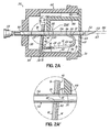
- FIGS. 2A and 2B are cross-sectional views of a second embodiment of a needle guard having a housing and the clip of FIG. 1, showing the clip in first and second states with a sharp tip of a needle exposed and protected, respectively, for purposes of explaining certain principles of the present invention;
- FIGS 2A' and 2B' are detail views of portions of FIGS. 2A and 2B, respectively for purposes of explaining certain principles of the present invention;
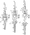
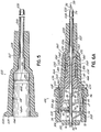
- FIGS. 3A-3C are side views of a catheter assembly incorporating the various aspects of the present invention including a third embodiment of a needle guard for a needle of the catheter assembly;
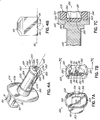
- FIG. 4A is perspective view of a nose portion of the needle guard housing of FIGS. 3A-3C for purposes of explaining certain additional principles and aspects of the present invention;
- FIG. 4B is a rear view of the proximal aspect of the nose portion of FIG. 4A;
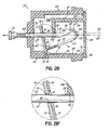
- FIG. 5 is a cross-sectional view of the catheter hub of FIGS. 3A-3C for purposes of explaining the duckbill catheter hub release mechanism feature of the present invention;
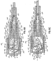
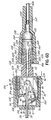
- FIGS. 6A-6D are cross-sectional views of the catheter assembly of FIGS. 3A-3C for purposes of illustrating operation of the duckbill catheter hub release mechanism of the second embodiment of the needle guard in accordance with certain principles of the present invention;
- FIGS. 7A and 7B are end views of the confronting faces of the needle guard and the needle hub, respectively, of FIGS. 3A-3C, for purposes of illustrating an anti-rotation feature of the present invention;
- FIG. 7C is a cross-sectional, partial view as taken along
lines 7C-7C of FIG. 7B, showing the needle hub and needle guard housing of FIGS. 7A and 7B in engagement with one another for purposes of explaining the anti-rotation feature of the present invention; - FIG. 8 is a perspective view of the needle hub and needle cannula of FIGS. 3A-3C illustrating a shroud at the distal end of the needle hub; and
- FIG. 9 is a cross-sectional, partial view of the catheter assembly of FIG. 3A with a protective sheath for purposes of explaining operation of the shroud in accordance with certain principles of the present invention.
- With reference to FIG. 1, there is shown one embodiment of a
needle guard 10 including a canted-plate clip 12 and aspring member 14.Clip 12 includes afirst wall 16 with anaperture 18, such as a circular hole, therethrough and asecond wall 20 interconnected by anintermediate wall 22 shown herein as comprising first andsecond struts inboard edge walls aperture 32 therebetween, andoutboard edges first wall 16 is a heel 34 (shown in dashed line in FIG. 1) such thatfirst wall 16 andheel 34 are disposed to opposite sides of thestruts Second wall 20 may have alip portion 36 projecting generally toward first wall such thatsecond wall 20 has a generally L-shape to it. Theouter corner surface 37 of the L-shapesecond wall 20 may be coined so as to define thereat anarcuate stylus 38.Clip 12 is advantageously an integral component of rigid metal (an example of which is stainless steel) or plastic. - Although
clip 12 is depicted in FIG. 1 as including twodiscreet struts clip 12 may includeonly strut 24, or only strut 26, as theintermediate wall 22. Further, thestrut second walls - Although
spring member 14 could take any desired form of stored energy device, such as a coil or other wound spring, compressible foam substance or other material, or a compressible bladder, by ways of example, it will be described herein in the advantageous form of a leaf spring having afirst end 40 with anopening 41 associated with aninner surface 42 of clipfirst wall 16 so as to overlieaperture 18 thereof, and having an elongatedleaf 44 extending from thefirst wall 16 past theedges struts aperture 32 to afree end 46 of theleaf 44.Spring member 14 could be an integral part ofclip 12, such thatfirst end 40 is part offirst wall 16 withleaf 44 extending therefrom. In that case,leaf 44 is advantageously thinner and more resilient thanfirst wall 16 for purposes hereinafter to be described. Or, as shown in FIG. 1,spring member 14 is a separate, resilient component withfirst end 40 bearing against, and advantageously secured to, such as by welding or the like,inner surface 42. - With reference to FIGS. 2A and 2B, there is shown a second embodiment of a
needle guard 50 for aneedle 52, such as a hollow hypodermic needle, a hollow or solid catheter insertion needle, or other similar sharp cannulae, attached to and extending from aneedle hub 54, which in this embodiment is shown as adapted for a hypodermic needle thus defining a female luer lock attachment but could also or alternatively define a flash chamber.Needle 52 has aneedle shaft 56 secured to and extending fromneedle hub 54 to a distal,sharp tip 58. While not required, theshaft 56 may be of a constant cross-sectional diameter.Needle guard 50 includes ahousing 60 having aproximal opening 62 and adistal opening 64 sized to slidably receive theshaft 56 ofneedle cannula 52 through the housing such that in a first position ofneedle 52,sharp tip 58 may be distally exposed as shown in Fig. 2A, or in a second position ofneedle cannula 52,sharp tip 58 is pulled back (by either pullingneedle shaft 56 proximally or pushinghousing 60 distally, both referred to herein as proximal movement of needle cannula 52) intohousing 60 as seen in Fig. 2B.Clip 12, whereinaperture 18 thereof is nominally sized relative toneedle shaft 56 to selectively slidably receive or grip same, andspring member 14 ofneedle guard 10 of FIG. 1 are included as the active element to protecttip 58 withinhousing 60 as will now be described. -
Clip 12 is situated withinhousing 60 such thataperture 18 is generally aligned along thelongitudinal axis 65 ofneedle cannula 52, which axis is also defined betweenopenings housing 60 and such thatspring member 14 extends into operative engagement with a bearingsurface 68 defined, for example, along aninner wall 70 ofhousing 60.Leaf 44 ofspring member 14 andintermediate wall 22 are thus to the same side ofneedle shaft 56.Clip 12 has a first state, shown in Fig. 2A, in whichfirst wall 16 is positioned generally vertically, although advantageously over-center distally, to allowneedle shaft 56 to be slidably received throughaperture 18 such that theinner periphery 18' ofaperture 18 does not bite or grip intoneedle shaft 56 as seen in FIG. 2A'. In that first state ofclip 12,second wall 20 has a portion,advantageously stylus 38 thereof, adapted to bear againstshaft 56, andheel 34 is adjacentinner surface 70 and abuttingledge 72 ofhousing 60. Whenneedle 52 is in the first position withtip 58 extending distally beyondclip 12, and particularly beyond opening 64 ofhousing 60,shaft 56 is in bearing relationship withstylus 38. -
Spring member 14 biases clip 12 to cantfirst wall 16 proximally toward a second state shown in FIG. 2B with theneedle 52 in the second position withsharp tip 58 ofneedle 56 withinhousing 60 such thattip 58 thereof is proximal oflip 36. Oncetip 58passes lip 36,heel 34 pivots aboutledge 72 asfirst wall 16 cants to bringaperture periphery 18' into biting engagement withshaft 56 to thereby grip same, as seen in FIG. 2B', to resist further proximal movement ofneedle 52 relative tohousing 60.Second wall 20, and especiallylip 36 thereof, moves through and beyondaxis 65 to go beyondtip 58 as seen in Fig. 2B, such thatsecond wall 20 now confronts and thus blockstip 58 from reemerging distally fromhousing 60.Lip 36 cooperates to confinetip 58 should it be able to move distally by some amount such thattip 58 is capped byclip 12 in the second state thereof. - As seen particularly in FIG. 2A,
intermediate wall 22 is not at a right angle tofirst wall 16. Rather,intermediate wall 22 extends at an included angle α of less than 90 degrees, and advantageously between about 83 degrees and about 87 degrees, therefrom and towardsneedle shaft 56. The angling of theintermediate wall 22 allowsfirst wall 16 to be slightly distally over-center or tilted (depending upon the gauge of needle 52) so that the degree of clip rotation to achieve the second state is increased as compared to avertical wall 16 as in prior devices. The distal tilting is only a few degrees withhole 18 sized not to bite intoneedle shaft 56 whenwall 16 is distally tilted. The increased degree of clip rotation helps assure thatsharp tip 58 will be capped, even in the worst-case orientation oftip 58 as shown in Fig. 2B. Advantageously,needle 52 will be oriented 90° or 180° from that shown in Fig. 2B. Also, by making the included angle betweenwalls wall 22 typically angles towardsneedle shaft 56 such that theclip 12 is not as likely to bind againsthousing 60 even with larger gauge needles 52. Also,heel 34 may be at an angle of about 90 degrees to wall 22 such thatheel 34 andwall 16 need not be coplanar. - In the second position of
needle 52, withclip 12 in the second state, it will be appreciated that there is a flexing force on thedistal tip end 58 ofneedle 52 which attempts to align that portion ofneedle shaft 56 withaperture 18. Were theshaft 56 to flex in that manner, there could be a reduction or loss of bite ofperiphery 18' onshaft 56, such thatneedle 52 might be able to be pulled proximally out ofneedle guard 50. To reduce that possibility, aneedle support 80 is preferably provided adjacent aplane 82 extending transverse, and possibly tangent, to thecylinder 84 defined byneedle shaft 56 in the first position thereof (see FIG. 4B).Needle support 80 may be defined at the end of an integral projectingmember 88 ofhousing 60, and advantageously may include a seat 90 (FIG. 4A) sized to slidably receive a portion ofneedle shaft 56 thereon.Seat 90 may be a slot or groove that complements the cylindrical shape of the outer surface of theneedle shaft 56. In addition to theneedle support 80, theneedle 52 is also supported by theproximal opening 62 in thehousing 60. These two points (needle support 80 and proximal opening 62) cooperate to holdneedle 52 level and secure, and allow for theclip 12 to exert a gripping force onneedle shaft 56 without adverse flexing thereof. A flex-limit stop in the form of a rib 91 (shown in dashed line in FIG. 4A as a lateral rib, but could be a longitudinal rib) may be included on the upper surface of projectingmember 88 or, alternatively, a flex-limit stop rib 91' (shown in dashed line in Figs. 2A and 2B) could be included as part of the housinginterior surface 70 abovemember 88 to limit flexing (advantageously to .006") ofmember 88 such as from leveraging ofneedle shaft 56. -
Housing 60 has a barrel or canisterproximal portion 94 and adistal cap portion 96.Canister portion 94 includes inner wall 70 (and rib 91' if provided) andback wall 98 withopening 62 and amouth 100 sized to matingly receivecap 96 thereto.Cap 96 includesopening 64, and is advantageously secured tomouth 100 ofcanister 94, such as by snap-fit, press-fit, and/or adhesive or ultrasonic welding.Canister 94 andcap 96 may have any desired cross-sectional shape, such as generally circular, such thathousing 60 is generally cylindrical. Advantageously, the cross-sectional shape is rectangular by flattening opposed aspects thereof (as seen in FIG. 7A) so as to have a low profile allowing for a desirably shallow insertion angle.Housing 60 may also include finger ridges (not shown) forneedle guard 50 to facilitate use by a medical practitioner (also not shown). Further, althoughdistal end 58 ofneedle 52 is shown extending freely fromneedle guard 50, those skilled in the art will recognize thatneedle shaft 56 could also be received through a catheter assembly (such asassembly 200 of FIG. 3A). Further, whilefirst wall 16 is shown as being rectangular,first wall 16 could be any other shape, such as square or disc-like, andaperture 18 could be other than a circular hole, provided tilting offirst wall 16 into the second state ofclip 12 results in gripping theneedle shaft 56. - The foregoing construction and relationship of the components is believed to provide a needle guard that has very low drag forces, such that the tactile and audible sensations thereof are acceptable to the medical practitioner (not shown), while at the same time providing reliable protection of
tip 58 thereby minimizing risk of accidental needle sticks therefrom. - In use,
needle 52 is inserted into a patient (not shown) possibly with a syringe (not shown) attached toneedle hub 54. After injecting medication, for example, whilehousing 60 is held steady,needle hub 54 andneedle 52 are retracted to withdrawneedle 52 from the patient and to withdrawneedle tip 58 proximally intohousing 60. Alternatively,needle 52 can be removed from the patient withhousing 60 in placeadjacent hub 54, and thenhousing 60 can be pushed down alongshaft 52 to withdrawneedle tip 58 proximally intohousing 60. In either case,spring member 14 biases clip 12 toward the second state to protect theneedle tip 58. Continued attempted proximal movement of theneedle 52 results in increased binding force applied toneedle shaft 56 thereby resisting such movement. Further,lip 36 of clipsecond wall 20 is now positioned to the other side oflongitudinal axis 65 and beyondtip 58 of theneedle 52. As a result, attempts to push theneedle 52 distally will bringtip 58 underneathlip 36 and/or againstsecond wall 20 to block theneedle tip 58. - With reference to FIGS. 3A-3C, there is shown a
catheter assembly 200 including a third embodiment of aneedle guard 202 for protecting thetip 58 ofneedle 52.Needle guard 202 may be essentially the same asneedle guard 50 of FIGS. 2A and 2B, except that it also includes afinger tab 203 and pair ofduckbills 204, 206 (see FIG. 3C) as will be described. Further,needle 52 is a catheter insertion needle with aneedle hub 208 shown as defining a flash chamber.Flash chamber 208 may include a ventedport 210. -
Catheter assembly 200 has acatheter hub 220 defining luer lugs 222 at itsproximal end 224 and has acatheter tube 226 secured by eyelet 227 (FIG. 5) to, and extending distally from thedistal end 228 of,catheter hub 220.Needle shaft 56 extends throughhousing 230 ofneedle guard 202 and throughcatheter hub 220 andcatheter tube 226 withtip 58 exiting thedistal end 232 thereof in a first position ofneedle 52 as seen in FIG. 3A.Housing 230 ofneedle guard 202 includesproximal canister 94, but has a modifiedcap 234, similar to cap 96 of FIG. 2A, but defining anose portion 236 including theduckbills Needle support 208 is pulled proximally relative toneedle guard 202 to begin to separateneedle support 208 andhousing 230 ofneedle guard 202 as seen in FIG. 3B. Continued proximal movement ofneedle 52 bringstip 58 intohousing 230 to be protected in the secured position thereof (as described in connection with FIGS. 2B and 2B') and to also allow for release ofhousing 230 fromcatheter hub 220 as seen in FIG. 3C. - With further reference to FIG. 4A, extending distally from
nose portion 236 ofcap 234 ofhousing 230 are a pair of cooperatingmembers Members distal ends passageway 258 nominally sized (also referred to herein as an inner diameter) to normally receive theshaft 56 of theneedle 52 freely therethrough without changing the size ofpassageway 258 and thus without normally imposing significant drag forces onshaft 56. At least one, and advantageously both, ofmembers detent 260 atdistal ends annular ring 262 and giving the cooperatingmembers respective duckbills Detents 260 may be distally chamfered as at 263. - With reference to FIG. 5, it will be seen that
catheter hub 220 includes aninner chamber 264 defined byinterior surface 266 ofcatheter hub 220 having aproximal portion 267 tapered in accordance with ISO or other applicable standards for female luers. A generallyannular rib 268 extends radially inwardly frominterior surface 266 intochamber 264.Rib 268 is advantageously distal of luer taperedportion 267 so as not to interfere with male luer taper connections tocatheter hub 220.Annular rib 268 anddetents 260 cooperate to holdneedle guard 202 tocatheter hub 220 in the first position of needle cannula 52 (FIG. 3A) and to allow for release thereof by movingneedle cannula 52 proximally towards the second position (FIG. 3C). In this regard, and with further reference to FIG. 6A, it will be seen that in the first position ofneedle cannula 52,shaft 56 thereof is inpassageway 258 thus limiting the ability of either or both of cooperatingmembers detents 260 define an outer diameter ofannular ring 262 that is slightly greater than the inner diameter ofannular rib 268 and which may closely correspond to the inner diameter of catheter hubinterior surface 266 just distal ofannular rib 268 as at 270. Thus, withneedle shaft 56 between cooperatingmembers detents 260 provide a generally rigid hold tocatheter hub 220 by cooperating with the distal-facingsurface 272 ofrib 268. Even as needle cannula progresses proximally to bringtip 58 towardshousing 230, as seen in FIG. 6B,shaft 56 still provides a block to the radially inwardly flexing ofmembers - With the
needle cannula 52 in the first position (FIG. 6A),detents 260 are seated pastrib 268 incatheter hub 220 with a light frictional fit that desirably allows the healthcare user (not shown) to rotatecatheter hub 220 relative toneedle guard 202. It is not untilneedle shaft 56 is effectively proximally beyondpassageway 258, such as withtip 58 protected byneedle guard 202 in the second position ofneedle 52 as seen in Fig. 6C, that either or both ofmembers needle guard 202 causes one or both ofduckbills detents 260 overcomeannular rib 268, and to then flex or uncompress back to the nominal position. As theinterior surface 267 portion is tapered in accordance with luer standards, the minimum inner diameter thereof is generally not less than, and is advantageously larger than, the maximum outer diameter defined bydetents 260, such that the detents generally will not adversely scrape onsurface 266 proximal ofrib 268 as themembers needle guard 202 is allowed to easily come away fromcatheter hub 220, as seen in Fig. 6D, without any adverse feel or scraping and without any specific, difficult or strong tugging action of the user (not shown). Similarly, withneedle shaft 52 out from withinpassageway 258,duckbills catheter hub 220 by pushing them into hub 220 (or pushinghub 220 overduckbills 204, 206) such thatdetents 260 impact againstrib 268 to cause the cooperatingmembers detents 260 are distally beyondrib 258 at which time they flex back out to lightly hold tocatheter hub 220.Needle shaft 52 may then be loaded to resist inward flexing ofmembers shaft 52 in place,duckbills hub 220.Chamfers 263 may help with loadingduckbills catheter hub 220. - Use of
rib 268 overcomes drawbacks associated with prior recess-based duckbill release mechanisms. To that end, the rib is easier to manufacture and avoids requiring detents that are so large diametrically that they might drag or scrape on the interior surface of the catheter hub during removal. - The size of the
passageway 258 may be closely dimensioned to the diameter ofneedle shaft 56 so thepassageway 258 is largely taken up by the presence ofneedle shaft 56. Compression or other inward flexing of the cooperatingmembers members catheter hub 220. Tolerance of the gap between the relative inner diameter ofpassageway 258 of cooperatingmembers needle shaft 56 may be selected to reduce the likelihood of removal of theduckbills catheter hub 220 whenneedle 52 is present. These tolerances may vary for different gauge needles although clearances of between .0065" and .0135" are advantageous. -
Members member passageway 258. To that end, the radial depth of eachridge 280 may be selected based upon the gauge ofneedle 52, with the radial depth ofridge 280 being inversely related to the gauge of theneedle 52 such that the radial depth is larger for small gauge needles and vice versa.Ridges 280 might be eliminated altogether for larger gauge needles 52. The arcuate shape and selective depth ofridges 280 to define the inner diameter ofpassageway 258 results in a generally consistent level of force between theduckbills catheter hub 220 across a range of needle gauges, such that the medical practitioner (not shown) will have generally the same sense of feel and touch with the devices across a range of gauges. Cooperatingmembers rib 268 is shown as being generally continuous, it may have one or more gaps (not shown). Advantageously, any such gap(s), if provided, would each be smaller than a circumferential width of thedetent 260. - The
needle guard duckbills catheter hub rib 268 cooperate to define a duckbill release mechanism which, as are shown herein, may be combined with an active element to protectneedle tip 58 in the form of a canting-plate clip. However, the duckbill release mechanism is not limited in use to such active elements, but may be used with other clip designs and even non-clip-based needle guards such as those including housings that served as a needle guard. By way of example, the needle guard can be the needle guard housing of the PROTECTIV Safety I.V. Catheter being marked by Medex, Inc., the assignee hereof, and/or those shown inU.S. Patent Nos. 4,762,516 and4,747,831 , or the active element can include other structure to grip and/or block the needle as shown in or ofU.S. Patent Nos. 4,978,344 ;5,215,528 ;5,332,517 ;5,328,482 ; and5,558,651 ;European Patent No. 0,352,928 B2 ; andU.S. Patent Application Nos. 10/905,047 and10/906,171 - Referring to FIGS. 7A-7C, in one aspect, the
needle hub 208 andhousing 230 include cooperatingstructure needle 52 to enhance stability when beginning a needle stick. More specifically,housing 230 includes at its proximal face 304 a projectinglug 300, having a non-circularperipheral edge 306. A recess ordepression 302, also with a non-circularperipheral edge 308, is disposed in thedistal face 310 ofneedle hub 208. As a consequence, whenneedle support 208 isadjacent housing 230 in the first position ofneedle 52, as seen in FIG. 7C, faces 304 and 310 are confronting withlug 300 engaging inrecess 302 to hold the components against rotation. Whenneedle 52 is moved out of the first position, lug 300 andrecess 302 disengage thus allowing for relative rotation ofhub 208 andneedle guard 202. Theperipheral edges lug 300 andrecess 302 are of complementary shape and advantageously define non-circular peripheries, such as a square, oval, or hexagon, for example. However, it will be understood that other complementary shapes may be used to prevent relative rotation betweenhousing 230 andneedle hub 208. Further theperipheral edge 308 ofrecess 302 may include one or more notch-outs as at 312.Needle 52 is secured tohub 208 such as by adhesive 313 in adhesive well 314 concentric withneedle 52. - Referring to FIGS. 8 and 9, in another aspect,
needle hub 208 advantageously has associated with it asplit shroud 320.Split shroud 320 has opposedarcuate legs hub 208.Legs portions canister 94 ofneedle guard housing 230 and opposed portions of clip 12) in the first position of theneedle 52 as seen in FIGS. 3A and 9, and to be spaced therefrom in the second position of theneedle 52 as seen in FIG. 3C. Advantageously,legs needle guard 220, such asfinger tab 203, is exposed therebetween in the first position ofneedle cannula 52 as seen in Fig. 3A. In the first position ofneedle cannula 52, shown in FIG. 9, splitshroud 320 overlies a portion of theneedle guard 202, such ascanister portion 94 ofhousing 230 and/orclip 12 leavingfinger tab 203 exposed. Thelegs split shroud 320 may be sized and positioned such that they engagehousing 230 with a friction fit. Prior to use, aprotective sheath 370 covers atleast catheter tube 226 and possiblycatheter hub 220,needle tip 58, and part or all ofsplit shroud 320. Advantageously, splitshroud 320 is disposed between theproximal mouth portion 372 ofsheath 370 andneedle guard 202. As a consequence, if an end user (not shown) grips thesheath portion 372, that force will be transmitted to splitshroud 320, rather than directly toneedle guard 202, to reduce the likelihood of inadvertently activatingneedle guard 202 or pullingneedle guard 202 loose fromcatheter hub 220 before the device is ready for use.Mouth portion 372 may have a gap (not shown) to exposefinger tab 203. However, in use,needle 52 may be readily removed such as by pushing onfinger tab 203 exposed throughsplit shroud 320. - In use of
catheter assembly 200,sheath 370 is removed, andneedle tip 58 inserted into a patient (not shown) to positioncatheter tube 226 as described, including if desired by rotation ofcatheter hub 220 relative toneedle guard 202, but advantageously without relative rotation betweenneedle hub 208 andneedle guard 202. Once positioned as desired,needle hub 208 andneedle 52 are moved proximally, such as with use of finger tab 203 (exposed through split shroud 320) as is well understood, to pullshaft 56 out of thecatheter tube 226 andcatheter hub 220, and toward a second position withtip 58 protected byneedle guard 202.Needle guard 202 is similarly removed fromcatheter hub 220 leavinghub 220 ready for use. Advantageously, the drag forces onneedle shaft 56 due toclip 12 are as low as possible. Moreover, the drag forces are advantageously lower than the forces required to separate theduckbills catheter hub 202, whether or notshaft 56 is inpassageway 258. Still further advantageously, the force required to separate theduckbills catheter hub 220 withshaft 56 in passageway 258 (referred to as "catheter separation force") is greater than, and most advantageously is at least twice, the force necessary to let them come loose when thepassageway 258 is not obstructed byneedle shaft 56 such as in the second position of needle 52 (referred to as "catheter release force"). The catheter release force may be determined by the "duckbill free length," which is the length of the cooperatingmembers members member members ridges 280 provide a generally consistent level of catheter release force (and/or catheter separation force) across a range of gauges ofneedle 52. That consistency is also enhanced by the lack of scraping betweendetents 260 andcatheter hub surface 267. As can thus be seen,catheter assembly 200 provides a passive release ofneedle guard 202 fromcatheter hub 220. The normal activity of retractingneedle hub 208 fromcatheter hub 220 activatesneedle guard 202 without any additional action by the healthcare worker (not shown). Similarly, further retraction of theneedle hub 208, after activation, easily releasesneedle guard 202 fromcatheter hub 220 without additional manipulation by the healthcare worker. - By virtue of the foregoing, individually and in various combinations, there are thus provided canting-plate needle guards that have improvements and enhancements as compared to prior canted-plate design. Also, by virtue of the foregoing, individually and in various combinations, there are thus also provided improvements to needle guards which can be used not only with canting-plate clips, but with other needle guard designs as well.
- While the present invention has been illustrated by the description of embodiments thereof, and while the embodiments have been described in considerable detail, it is not intended to restrict or in any way limit the scope of the appended claims to such detail. Additional advantages and modifications will readily appear to those skilled in the art. For example, while the Figures and the description herein show
clip 12 as having afirst wall 16 that cants proximally upon retraction of theneedle 52, it will be understood by those of skill in the art that clip 12 could be designed such thatwall 16 cants distally. Further,second wall 20 ofclip 12 could include an opening (not shown) for a guide wire but not with clearance forneedle 52 in the second sized state ofclip 12. Further still,stylus 38 ofsecond wall 20 could join directly tointermediate wall 22 ofclip 12, such that the stylus defines the second wall. Further still,spring member 14 could extend pastoutboard edges intermediate wall 22 rather than inboardedges intermediate wall 22. Also, ifclip 12 andspring member 14 are sized small enough, they could be fitted directly into a catheter hub with a bearing surface in the catheter hub.
Claims (27)
- A safety catheter device comprising a catheter hub and a catheter tube extending therefrom, a needle having a needle shaft terminating in a sharp tip, a clip having a first wall with an aperture adapted to slidably receive the needle shaft therethrough in a first state of the clip and to grip the needle shaft in a second state of the clip, the clip having a second wall with a portion adapted to bear against the shaft in the first state and being adapted to confront a tip of the needle in the second state, and a strut connecting the first and second walls, the needle having a first position slidably received through the aperture of the clip first wall, in bearing relationship with the clip second wall portion, and extending through the catheter tube with the sharp tip exposed in the first state of the clip, the needle having a second position in which the needle tip has been pulled out of the catheter tube past the clip second wall such that the clip moves towards the second state and grips the needle shaft with the tip blocked by the clip second wall, a spring member biasing the clip toward the second state, and a needle support fixedly positioned adjacent a plane transverse to a cylinder defined by the needle shaft in the first position of the needle whereby to limit deflection of the needle in at least the second position of the needle.
- The device of claim 1, further comprising a housing adapted to slidably receive the needle therethrough, the clip and spring member being contained within the housing.
- The device of claim 2, the housing being removably coupled to the catheter hub.
- The device of claim 3, further comprising a duckbill extending from the housing for removably coupling the housing to the catheter hub.
- The device of any one of claims 2 to 4 further comprising a needle hub fixedly coupled with the needle, the needle support including a shroud sized to overlie opposed portions of the housing in the first position of the needle and to be spaced therefrom in the second position of the needle, and a sheath enclosing at least the catheter tube and the needle tip, and overlying at least a portion of the shroud.
- The device of any one of claims 2 to 4, further comprising a needle hub fixedly coupled with the needle, the needle support adjacent the housing in the first position of the needle, the needle support and the housing including cooperating structure to hold them against relative rotation in the first position of the needle.
- The device of any one of claims 2 to 6, further comprising a needle hub fixedly coupled to the needle, the needle hub including a shroud sized to overlie opposed portions of the clip in the first position of the needle and to be spaced therefrom in the second position of the needle, and a sheath enclosing at least the catheter tube and the needle tip, and overlying at least a portion of the shroud.
- A needle protector device comprising a housing including an entry aperture and an exit aperture with a plane intersecting respective edges of the entry and exit apertures, a clip positioned within the housing and having a first wall with an aperture adapted to slidably receive a needle shaft therethrough in a first state of the clip and to grip the needle shaft in a second state of the clip, the clip having a second wall with a portion adapted to bear against the shaft in the first state and being adapted to confront a tip of the needle in the second state, and a strut connecting the first and second walls, and a needle support within the housing and confronting the plane.
- The device of claim 8, further comprising a spring member in the housing and biasing the clip toward the second state.
- The device of any one of claims 1 to 7 and 9, the spring member being a leaf spring.
- The device of either claim 8 or claim 9, further comprising a needle hub with a needle extending therefrom the needle having a needle shaft terminating in a sharp tip, the needle having a first position slidably received through the aperture of the clip first wall, in bearing relationship with the clip second wall portion with the tip extending from the housing in the first state of the clip, the needle having a second position in which the needle tip has been pulled into the housing past the clip second wall such that the clip moves towards the second state and grips the needle shaft with the tip blocked by the clip second wall.
- The device of claim 11, the needle hub including a shroud sized to overlie opposed portions of the housing in the first position of the needle and to be spaced therefrom in the second position of the needle and a sheath enclosing at least the needle tip and overlying at least a portion of the shroud.
- The device of claim 11, the needle hub adjacent the housing in the first position of the needle, the needle support and the housing including cooperating structure to hold them against relative rotation in the first position of the needle.
- The device of any one of claims 2 to 5 or 13, the needle support being defined on a projection affixed to the housing.
- The device of claim 14, the needle support including a seat sized to slidably receive a portion of the needle shaft thereon.
- The device of either claim 1 or claim 8, further comprising a flex limit rib associated with the needle support.
- The device of claim 8, further comprising a flex limit rib associated with the housing.
- The device of claim 14, further comprising a flex limit rib adapted to limit flex of the projection.
- The device of claim 18, the flex limit rib being associated with the projection.
- The device of claim 18, the flex limit rib being associated with the housing.
- The device of any preceding claim, the clip second wall portion defining a stylus.
- The device of any preceding claim, the clip second wall having a lip adapted to confine the needle tip in the second state of the clip.
- The device of any preceding claim, further comprising a ledge within the housing and the clip further comprising a heel, the first wall and heel being disposed to opposite sides of the strut, the heel abutting the ledge in the first state of the clip and pivoting about the ledge as the clip moves from the first state toward the second state.
- The device of claim 23 as dependent on claim 1, further comprising a housing adapted to slidably receive the needle therethrough, the clip, the spring member, and the ledge being contained within the housing.
- The device of any preceding claim, the needle support including a seat sized to slidably receive a portion of the needle shaft thereon.
- The device of any preceding claim, the needle support and clip second wall being disposed to opposite sides of the needle shaft in the clip first state.
- The device of any preceding claim, the needle support being disposed between the first and second walls in the clip second state.
Applications Claiming Priority (5)
| Application Number | Priority Date | Filing Date | Title |
|---|---|---|---|
| US11/161,551 US7753877B2 (en) | 2005-08-08 | 2005-08-08 | Needle guard strut wall clip |
| US11/161,553 US20070038187A1 (en) | 2005-08-08 | 2005-08-08 | Needle guard mechanism with anti-rotation feature |
| US11/161,547 US20070038183A1 (en) | 2005-08-08 | 2005-08-08 | Needle guard clip with stylus |
| US11/161,546 US20070038182A1 (en) | 2005-08-08 | 2005-08-08 | Needle guard mechanism with needle support |
| US11/161,541 US20070073221A1 (en) | 2005-08-08 | 2005-08-08 | Needle guard mechanism with leaf spring |
Publications (2)
| Publication Number | Publication Date |
|---|---|
| EP1752180A2 true EP1752180A2 (en) | 2007-02-14 |
| EP1752180A3 EP1752180A3 (en) | 2008-03-12 |
Family
ID=37946074
Family Applications (5)
| Application Number | Title | Priority Date | Filing Date |
|---|---|---|---|
| EP06254009A Ceased EP1752184A3 (en) | 2005-08-08 | 2006-07-31 | Needle guard strut wall clip |
| EP06253993A Withdrawn EP1752180A3 (en) | 2005-08-08 | 2006-07-31 | Needle guard mechanism with needle support |
| EP06253990.3A Not-in-force EP1752178B1 (en) | 2005-08-08 | 2006-07-31 | Needle guard mechanism with leaf spring |
| EP06253992A Withdrawn EP1752179A3 (en) | 2005-08-08 | 2006-07-31 | Needle guard clip with stylus |
| EP06253994A Withdrawn EP1752181A1 (en) | 2005-08-08 | 2006-07-31 | Needle guard mechanism with anti-rotation feature |
Family Applications Before (1)
| Application Number | Title | Priority Date | Filing Date |
|---|---|---|---|
| EP06254009A Ceased EP1752184A3 (en) | 2005-08-08 | 2006-07-31 | Needle guard strut wall clip |
Family Applications After (3)
| Application Number | Title | Priority Date | Filing Date |
|---|---|---|---|
| EP06253990.3A Not-in-force EP1752178B1 (en) | 2005-08-08 | 2006-07-31 | Needle guard mechanism with leaf spring |
| EP06253992A Withdrawn EP1752179A3 (en) | 2005-08-08 | 2006-07-31 | Needle guard clip with stylus |
| EP06253994A Withdrawn EP1752181A1 (en) | 2005-08-08 | 2006-07-31 | Needle guard mechanism with anti-rotation feature |
Country Status (7)
| Country | Link |
|---|---|
| US (6) | US7753877B2 (en) |
| EP (5) | EP1752184A3 (en) |
| CN (1) | CN101257941A (en) |
| AR (1) | AR057492A1 (en) |
| CA (5) | CA2553109C (en) |
| MX (1) | MXPA06009008A (en) |
| TW (1) | TWI337546B (en) |
Families Citing this family (102)
| Publication number | Priority date | Publication date | Assignee | Title |
|---|---|---|---|---|
| US6749588B1 (en) | 1998-04-09 | 2004-06-15 | Becton Dickinson And Company | Catheter and introducer needle assembly with needle shield |
| US8066678B2 (en) * | 2001-12-17 | 2011-11-29 | Bard Access Systems, Inc. | Safety needle with collapsible sheath |
| DE20210394U1 (en) | 2002-07-04 | 2002-09-12 | Braun Melsungen Ag | catheter introducer |
| US7776016B1 (en) | 2004-02-26 | 2010-08-17 | C. R. Bard, Inc. | Huber needle safety enclosure |
| ATE424879T1 (en) | 2005-07-06 | 2009-03-15 | Vascular Pathways Inc | INTRAVENOUS CATHETER INSERTION DEVICE AND METHOD OF USE |
| US7753877B2 (en) | 2005-08-08 | 2010-07-13 | Smiths Medical Asd, Inc. | Needle guard strut wall clip |
| US8251950B2 (en) | 2005-08-08 | 2012-08-28 | Smiths Medical Asd, Inc. | Needle guard clip with heel |
| US7597681B2 (en) * | 2005-08-08 | 2009-10-06 | Smiths Medical Asd, Inc. | Needle guard mechanism with shroud |
| US7632243B2 (en) * | 2005-08-08 | 2009-12-15 | Smiths Medical Asd, Inc. | Duckbill catheter release mechanism |
| US8162881B2 (en) | 2005-08-08 | 2012-04-24 | Smiths Medical Asd, Inc. | Needle guard mechanism with angled strut wall |
| US8403886B2 (en) | 2005-08-08 | 2013-03-26 | Smiths Medical Asd, Inc. | Needle guard clip with lip |
| US8078671B2 (en) * | 2005-09-21 | 2011-12-13 | Sap Ag | System and method for dynamic web services descriptor generation using templates |
| US20070067388A1 (en) * | 2005-09-21 | 2007-03-22 | Angelov Dimitar V | System and method for configuration to web services descriptor |
| US8700681B2 (en) | 2005-09-28 | 2014-04-15 | Sap Ag | Method and system for generating schema to java mapping descriptors |
| US9454616B2 (en) * | 2005-09-28 | 2016-09-27 | Sap Se | Method and system for unifying configuration descriptors |
| US20070073771A1 (en) * | 2005-09-28 | 2007-03-29 | Baikov Chavdar S | Method and system for directly mapping web services interfaces and java interfaces |
| US8250522B2 (en) | 2005-09-28 | 2012-08-21 | Sap Ag | Method and system for generating a web services meta model on the java stack |
| US8010695B2 (en) * | 2005-12-30 | 2011-08-30 | Sap Ag | Web services archive |
| US8024425B2 (en) * | 2005-12-30 | 2011-09-20 | Sap Ag | Web services deployment |
| US20070156872A1 (en) * | 2005-12-30 | 2007-07-05 | Stoyanova Dimitrina G | Method and system for Web services deployment |
| US7814060B2 (en) * | 2005-12-30 | 2010-10-12 | Sap Ag | Apparatus and method for web service client deployment |
| US8382718B2 (en) | 2006-07-31 | 2013-02-26 | B. Braun Melsungen Ag | Needle assembly and components thereof |
| US8308691B2 (en) | 2006-11-03 | 2012-11-13 | B. Braun Melsungen Ag | Catheter assembly and components thereof |
| JP4994775B2 (en) | 2006-10-12 | 2012-08-08 | 日本コヴィディエン株式会社 | Needle point protector |
| US9220871B2 (en) * | 2006-11-22 | 2015-12-29 | Becton, Dickinson And Company | Needle shielding pawl structures |
| US9056188B2 (en) * | 2006-11-22 | 2015-06-16 | Becton, Dickinson And Company | Needle shielding flag structures |
| US8597253B2 (en) | 2007-04-20 | 2013-12-03 | Bard Access Systems | Huber needle with safety sheath |
| DE602008003791D1 (en) | 2007-05-07 | 2011-01-13 | Vascular Pathways Inc | INTRODUCTION OF INTRAVENOUS CATHETER AND BLOOD DETECTING DEVICE AND METHOD OF USE |
| US7713243B2 (en) * | 2007-09-25 | 2010-05-11 | Becton, Dickinson And Company | Tip shield for needle stick prevention |
| ES2788079T3 (en) * | 2007-11-21 | 2020-10-20 | Becton Dickinson Co | Needle safety device |
| CA2706585C (en) | 2007-11-21 | 2013-07-16 | Becton, Dickinson And Company | Safety needle guard |
| AU2013263723B2 (en) * | 2007-11-21 | 2016-01-14 | Becton, Dickinson And Company | Needle safety device |
| CN104338206B (en) * | 2008-03-17 | 2018-04-03 | 波利医疗有限公司 | Pin safety device |
| US7828774B2 (en) * | 2008-05-12 | 2010-11-09 | Harding Weston F | Sleeved clip safety |
| WO2013119258A1 (en) * | 2012-02-10 | 2013-08-15 | Dolor Technologies, L.L.C. | Systems and apparatus for facilitating intranasal treatment of a patient |
| US8231582B2 (en) | 2008-12-11 | 2012-07-31 | Bard Access Systems, Inc. | Device for removing a Huber needle from a patient |
| SE534021C2 (en) * | 2009-08-13 | 2011-04-05 | Vigmed Ab | Protective device for a catheter needle tip |
| US8323249B2 (en) | 2009-08-14 | 2012-12-04 | The Regents Of The University Of Michigan | Integrated vascular delivery system |
| CN102198303A (en) * | 2010-03-22 | 2011-09-28 | 维斯塔迈德研发有限公司 | Catheter introducer |
| SE535169C2 (en) | 2010-04-13 | 2012-05-08 | Vigmed Ab | Polymer protective device for a catheter needle tip |
| US8932258B2 (en) | 2010-05-14 | 2015-01-13 | C. R. Bard, Inc. | Catheter placement device and method |
| US9950139B2 (en) | 2010-05-14 | 2018-04-24 | C. R. Bard, Inc. | Catheter placement device including guidewire and catheter control elements |
| US10384039B2 (en) | 2010-05-14 | 2019-08-20 | C. R. Bard, Inc. | Catheter insertion device including top-mounted advancement components |
| US11925779B2 (en) | 2010-05-14 | 2024-03-12 | C. R. Bard, Inc. | Catheter insertion device including top-mounted advancement components |
| US9872971B2 (en) | 2010-05-14 | 2018-01-23 | C. R. Bard, Inc. | Guidewire extension system for a catheter placement device |
| WO2011146769A2 (en) | 2010-05-19 | 2011-11-24 | Tangent Medical Technologies Llc | Integrated vascular delivery system |
| US8814833B2 (en) | 2010-05-19 | 2014-08-26 | Tangent Medical Technologies Llc | Safety needle system operable with a medical device |
| US8257322B2 (en) * | 2010-06-02 | 2012-09-04 | Smiths Medical Asd, Inc. | Tip protector for a safety catheter |
| US9011388B2 (en) * | 2010-06-04 | 2015-04-21 | Smiths Medical Asd, Inc. | Passive safety portal device |
| FR2961701B1 (en) * | 2010-06-28 | 2014-06-20 | Braun Medical Sas | NEEDLE FOR INJECTING OR EXTRACTING FLUIDS WITH A SAFETY DEVICE FOR PROTECTING AGAINST INJURIES ON THE NEEDLE'S NEEDLE |
| CA2806393A1 (en) | 2010-09-10 | 2012-03-15 | C.R. Bard, Inc. | Systems for isolation of a needle-based infusion set |
| US10525234B2 (en) | 2010-09-10 | 2020-01-07 | C. R. Bard, Inc. | Antimicrobial/haemostatic interface pad for placement between percutaneously placed medical device and patient skin |
| US20140066894A1 (en) | 2010-09-10 | 2014-03-06 | C. R. Bard, Inc. | Self-Sealing Pad for a Needle-Based Infusion Set |
| WO2012039672A1 (en) * | 2010-09-23 | 2012-03-29 | Vigmed Ab | Needle tip shielding device |
| US8690833B2 (en) | 2011-01-31 | 2014-04-08 | Vascular Pathways, Inc. | Intravenous catheter and insertion device with reduced blood spatter |
| EP3563898B1 (en) | 2011-02-25 | 2020-11-11 | C.R. Bard, Inc. | Medical component insertion device including a retractable needle |
| US8764711B2 (en) | 2011-02-28 | 2014-07-01 | Injectimed, Inc. | Needle guard |
| US9238104B2 (en) | 2011-02-28 | 2016-01-19 | Injectimed, Inc. | Needle guard |
| US8486024B2 (en) * | 2011-04-27 | 2013-07-16 | Covidien Lp | Safety IV catheter assemblies |
| US9884156B2 (en) * | 2011-04-28 | 2018-02-06 | Sanofi-Aventis Deutschland Gmbh | Lockout element for dispense interface |
| WO2012146673A1 (en) * | 2011-04-28 | 2012-11-01 | Sanofi-Aventis Deutschland Gmbh | Dispense interface with lockout element |
| US9770562B2 (en) * | 2011-05-06 | 2017-09-26 | Sanofi-Aventis Deutschland Gmbh | Lock out member with different cross sections |
| USD903101S1 (en) | 2011-05-13 | 2020-11-24 | C. R. Bard, Inc. | Catheter |
| EP2760520A1 (en) | 2011-09-26 | 2014-08-06 | Covidien LP | Safety catheter |
| WO2013048768A1 (en) | 2011-09-26 | 2013-04-04 | Covidien Lp | Safety iv catheter and needle assembly |
| US8834422B2 (en) | 2011-10-14 | 2014-09-16 | Covidien Lp | Vascular access assembly and safety device |
| CN104203328B (en) * | 2012-03-23 | 2017-08-15 | 三菱铅笔株式会社 | Lancet device |
| US9522254B2 (en) | 2013-01-30 | 2016-12-20 | Vascular Pathways, Inc. | Systems and methods for venipuncture and catheter placement |
| US10357635B2 (en) | 2013-03-12 | 2019-07-23 | Teleflex Medical Incorporated | Catheter insertion device |
| US9717886B2 (en) | 2013-03-12 | 2017-08-01 | Teleflex Medical Incorporated | Safety clip for a needle |
| US11224724B2 (en) | 2013-03-12 | 2022-01-18 | Teleflex Medical Incorporated | Catheter insertion device |
| JP6138921B2 (en) * | 2013-04-01 | 2017-05-31 | テルモ株式会社 | Catheter assembly |
| US9199784B2 (en) * | 2013-10-07 | 2015-12-01 | Avanti U.S.A. Ltd. | Spring-biased flip top case for an aerosol canister |
| EP3102258A4 (en) | 2014-02-04 | 2017-12-27 | ICU Medical, Inc. | Self-priming systems and methods |
| US9555221B2 (en) | 2014-04-10 | 2017-01-31 | Smiths Medical Asd, Inc. | Constant force hold tip protector for a safety catheter |
| ES2834969T3 (en) * | 2014-04-18 | 2021-06-21 | Becton Dickinson Co | Multipurpose Blood Monitoring Safety Catheter Assembly |
| USD768849S1 (en) * | 2014-07-02 | 2016-10-11 | 3M Innovative Properties Company | Securement device |
| WO2016037127A1 (en) | 2014-09-05 | 2016-03-10 | C.R. Bard, Inc. | Catheter insertion device including retractable needle |
| USD903100S1 (en) | 2015-05-01 | 2020-11-24 | C. R. Bard, Inc. | Catheter placement device |
| WO2016178974A1 (en) | 2015-05-01 | 2016-11-10 | Centurion Medical Products Corporation | Catheter insertion system |
| WO2016187037A1 (en) | 2015-05-15 | 2016-11-24 | C.R.Bard, Inc. | Catheter placement device including an extensible needle safety component |
| CN105013042B (en) * | 2015-07-31 | 2017-10-31 | 中国医科大学附属第一医院 | Stem cell continuous injection system in minimally invasive coronary artery bypass graft |
| DK3552652T3 (en) | 2015-08-18 | 2021-07-12 | Braun Melsungen Ag | CATHETER FACILITIES WITH VALVES |
| USD783813S1 (en) * | 2015-11-17 | 2017-04-11 | Justin Duncan | Hose clamp for a urine catheter |
| CN106267521B (en) * | 2016-08-30 | 2023-04-07 | 苏州鱼跃医疗科技有限公司 | Safety device, catheter, introducer needle assembly, and indwelling needle |
| JP7051821B2 (en) | 2016-09-12 | 2022-04-11 | シー・アール・バード・インコーポレーテッド | Blood control for catheter insertion device |
| US10799679B2 (en) | 2016-12-05 | 2020-10-13 | Medline Industries, Inc. | Securement device and assembly |
| US10792438B2 (en) * | 2016-12-13 | 2020-10-06 | Becton, Dickinson And Company | Safety needle devices |
| TWD192264S (en) * | 2017-01-28 | 2018-08-11 | 狄巴克 錢卓拉 阿柔拉 | Safety clip |
| KR20190118187A (en) * | 2017-02-24 | 2019-10-17 | 백톤 디킨슨 앤드 컴퍼니 | Catheter assembly |
| JP6953541B2 (en) | 2017-03-01 | 2021-10-27 | シー・アール・バード・インコーポレーテッドC R Bard Incorporated | Catheter insertion device |
| EP3854439B1 (en) | 2017-03-23 | 2022-04-06 | Smiths Medical ASD, Inc. | Safety catheter with passive release |
| US10946176B2 (en) | 2017-04-06 | 2021-03-16 | Becton, Dickinson And Company | Intravenous catheter assembly with safety clip |
| WO2018191361A1 (en) | 2017-04-13 | 2018-10-18 | Teleflex Medical Incorporated | Catheter insertion device |
| USD890924S1 (en) * | 2017-06-02 | 2020-07-21 | Medline Industries, Inc. | Securement device assembly |
| WO2018224637A1 (en) | 2017-06-09 | 2018-12-13 | B. Braun Melsungen Ag | Adhesive encased protective caps for needle devices and related methods |
| WO2019173641A1 (en) | 2018-03-07 | 2019-09-12 | Bard Access Systems, Inc. | Guidewire advancement and blood flashback systems for a medical device insertion system |
| CN117045897A (en) * | 2018-05-03 | 2023-11-14 | 赫莫泰克医疗公司 | Needle safety system |
| USD921884S1 (en) | 2018-07-27 | 2021-06-08 | Bard Access Systems, Inc. | Catheter insertion device |
| WO2020127328A1 (en) | 2018-12-17 | 2020-06-25 | B. Braun Melsungen Ag | Over-the-needle catheter assemblies and related manufacturing method |
| EP4010057A4 (en) | 2019-08-19 | 2023-10-18 | Becton, Dickinson and Company | Midline catheter placement device |
| US11266792B2 (en) | 2019-10-28 | 2022-03-08 | FGC Holdings Limited | Single use safety needle guard |
Citations (9)
| Publication number | Priority date | Publication date | Assignee | Title |
|---|---|---|---|---|
| WO1990008564A1 (en) * | 1989-02-01 | 1990-08-09 | 167300 Canada Inc. | Disposable automatic hypodermic needle guard |
| EP0554841A1 (en) * | 1992-02-07 | 1993-08-11 | Becton, Dickinson and Company | Catheter introducer assembly including needle tip shield |
| US5584810A (en) * | 1995-07-11 | 1996-12-17 | Becton Dickinson And Company | Needle point guard assembly |
| US5697907A (en) * | 1993-07-20 | 1997-12-16 | Graphic Controls Corporation | Safety catheter |
| WO2001010488A1 (en) * | 1999-08-09 | 2001-02-15 | Arrow International, Inc. | Hypodermic needle guard |
| US20030100868A1 (en) * | 2001-03-15 | 2003-05-29 | Ferguson F. Mark | Safety shield for medical needles |
| WO2003103757A1 (en) * | 2002-06-06 | 2003-12-18 | Manan Medical Products, Inc. | Needle tip protector |
| US20050075609A1 (en) * | 2003-10-01 | 2005-04-07 | Latona Patrick C. | Protective needle clips |
| WO2006047737A2 (en) * | 2004-10-27 | 2006-05-04 | Sherwood Services Ag | Needle assembly including obturator with safety reset |
Family Cites Families (133)
| Publication number | Priority date | Publication date | Assignee | Title |
|---|---|---|---|---|
| US4778453A (en) * | 1986-04-07 | 1988-10-18 | Icu Medical, Inc. | Medical device |
| US4832696A (en) | 1987-03-05 | 1989-05-23 | Luther Medical Products, Inc. | Assembly of needle and protector |
| US4762516A (en) | 1987-03-05 | 1988-08-09 | Luther Medical Products, Inc. | Assembly of needle catheter protector |
| US4747831A (en) | 1987-04-29 | 1988-05-31 | Phase Medical, Inc. | Cannula insertion set with safety retracting needle |
| US4834718A (en) * | 1987-06-01 | 1989-05-30 | Michael McDonald | Safety needle apparatus |
| US4944725A (en) * | 1987-06-01 | 1990-07-31 | Mcdonald Michael | Safety needle apparatus |
| US4950252A (en) | 1987-11-02 | 1990-08-21 | Luther Medical Products, Inc. | Single hand actuated locking safety catheter and method of use |
| US4846805A (en) * | 1987-12-04 | 1989-07-11 | Icu Medical, Inc. | Catheter insert device |
| US5108379A (en) * | 1987-12-21 | 1992-04-28 | Stuart Dolgin | Fluid passing apparatus with means for covering the same |
| US5156599A (en) * | 1988-06-28 | 1992-10-20 | Sherwood Medical Company | Syringe and sliding locking needle shield |
| US4952207A (en) * | 1988-07-11 | 1990-08-28 | Critikon, Inc. | I.V. catheter with self-locating needle guard |
| USRE34416E (en) * | 1988-07-11 | 1993-10-19 | Critikon, Inc. | I.V. catheter with self-locating needle guard |
| US4929241A (en) * | 1988-08-05 | 1990-05-29 | Kulli John C | Medical needle puncture guard |
| US4944728A (en) * | 1988-10-17 | 1990-07-31 | Safe Medical Devices, Inc. | Intravenous catheter placement device |
| CA2001732A1 (en) | 1988-10-31 | 1990-04-30 | Lawrence A. Lynn | Intravenous line coupling device |
| US5458658A (en) * | 1989-02-01 | 1995-10-17 | Sero-Guard Corporation | Positive locking needle-mounted needle guard for needle supported catheters |
| US5662610A (en) * | 1989-02-01 | 1997-09-02 | Sircom; Richard C. | Automatic needle guard tip protection |
| US5000740A (en) * | 1989-04-10 | 1991-03-19 | Critikon, Inc. | Catheter with needle guard |
| US5205820A (en) * | 1989-06-16 | 1993-04-27 | Science, Incorporated | Fluid delivery apparatus |
| US5135504A (en) * | 1989-07-17 | 1992-08-04 | Mclees Donald J | Needle tip guard |
| US5205829A (en) * | 1990-02-09 | 1993-04-27 | Lituchy Andrew E | Safety disposable intravenous (I.V. assembly) |
| US5053017A (en) * | 1990-02-28 | 1991-10-01 | Chamuel Steven R | Hypodermic needle safety clip |
| US5558651A (en) * | 1990-04-20 | 1996-09-24 | Becton Dickinson And Company | Apparatus and method for a needle tip cover |
| US5279591A (en) * | 1990-07-16 | 1994-01-18 | Simon Alexander Z | Protector for needle catheter |
| US5026356A (en) | 1990-10-17 | 1991-06-25 | Smith Daniel E | Safety device for needles of hypodermic syringes |
| US5176655A (en) * | 1990-11-08 | 1993-01-05 | Mbo Laboratories, Inc. | Disposable medical needle and catheter placement assembly having full safety enclosure means |
| US5102394A (en) * | 1990-12-19 | 1992-04-07 | Abbott Laboratories | Catheter assembly with protective shield |
| CA2033361C (en) | 1990-12-28 | 2002-11-12 | Richard Sircom | Needle-mounted hypodermic needle guard |
| US5215525A (en) * | 1992-09-29 | 1993-06-01 | Sturman Warren M | Safety casing for intravenous catheter needle |
| US5376073A (en) * | 1992-11-23 | 1994-12-27 | Becton, Dickinson And Company | Locking safety needle assembly |
| US5425720A (en) | 1993-01-27 | 1995-06-20 | Rogalsky; Alena | Medical needle unit |
| US5549570A (en) * | 1993-01-27 | 1996-08-27 | Rogalsky; Alena | Medical needle unit |
| US5300045A (en) * | 1993-04-14 | 1994-04-05 | Plassche Jr Walter M | Interventional needle having an automatically capping stylet |
| US5601532A (en) * | 1993-07-20 | 1997-02-11 | Graphic Controls Corporation | Locking safety cover for sharp instruments |
| US5417659A (en) | 1993-07-20 | 1995-05-23 | Devon Industries, Inc. | Surgical instrument sharp end foil |
| US5344408A (en) | 1993-08-06 | 1994-09-06 | Becton, Dickinson And Company | Break-away safety shield for needle cannula |
| US5409461A (en) * | 1993-09-28 | 1995-04-25 | Becton Dickinson And Company | Catheter introducer assembly with needle shielding device |
| US5419766A (en) | 1993-09-28 | 1995-05-30 | Critikon, Inc. | Catheter with stick protection |
| US5348544A (en) * | 1993-11-24 | 1994-09-20 | Becton, Dickinson And Company | Single-handedly actuatable safety shield for needles |
| US5334158A (en) * | 1993-12-20 | 1994-08-02 | Mclees Donald J | Automatic needle tip guard for standard hypodermic needles |
| US6203527B1 (en) * | 1994-03-29 | 2001-03-20 | Filiberto P. Zadini | Bi-directional clamping guard for needle stick protection |
| US5769827A (en) * | 1994-08-25 | 1998-06-23 | Safeguard Needle International, Inc. | Safety needle apparatus and method |
| US5423766A (en) * | 1994-08-26 | 1995-06-13 | Becton, Dickinson And Company | Safety shield having spring tether |
| US5738660A (en) * | 1994-10-27 | 1998-04-14 | Luther Medical Products, Inc. | Percutaneous port catheter assembly and method of use |
| CA2168615A1 (en) * | 1995-03-07 | 1996-09-08 | Timothy J. Erskine | Catheter-advancement actuated needle retraction system |
| CA2169220A1 (en) * | 1995-03-16 | 1996-09-17 | Greg L. Brimhall | Control forward introducer needle and catheter assembly |
| US5830189A (en) * | 1995-06-07 | 1998-11-03 | Johnson & Johnson Medical, Inc. | Catheter hub to nose engagement |
| IL118551A (en) | 1995-06-07 | 2004-05-12 | Johnson & Johnson Medical | Protective needle cover containment |
| US5882337A (en) * | 1995-06-07 | 1999-03-16 | Johnson & Johnson Medical, Inc. | Tip protection device |
| US5599310A (en) * | 1995-06-07 | 1997-02-04 | Johnson & Johnson Medical, Inc. | I.V. catheter assembly with automatic cannula tip guard |
| DE69618405T2 (en) * | 1995-09-18 | 2002-08-01 | Becton Dickinson Co | Needle protection with collapsing cover |
| US5879337A (en) * | 1997-02-27 | 1999-03-09 | Injectimed, Inc. | Needle tip guard for hypodermic needles |
| ATE297231T1 (en) * | 1996-02-27 | 2005-06-15 | Injectimed Inc | NEEDLE TIP PROTECTION FOR SUBCUTANEOUS INJECTIONS |
| US6629959B2 (en) | 1996-02-27 | 2003-10-07 | Injectimed, Inc. | Needle tip guard for percutaneous entry needles |
| US5865806A (en) | 1996-04-04 | 1999-02-02 | Becton Dickinson And Company | One step catheter advancement automatic needle retraction system |
| SE513823C2 (en) * | 1996-05-31 | 2000-11-13 | Wiklund Ernst S G F | Point guard for puncture needles |
| US5735827A (en) * | 1996-09-26 | 1998-04-07 | Becton, Dickinson And Company | Needle assembly having locking enclosure |
| EP0832666A3 (en) | 1996-09-30 | 1998-08-26 | Becton, Dickinson and Company | Detachable blood seal |
| US5800395A (en) * | 1996-12-05 | 1998-09-01 | Mdc Investment Holdings, Inc. | Medical device with retractable needle |
| GB9708569D0 (en) | 1997-04-29 | 1997-06-18 | Smiths Industries Ltd | Catheter and needle assemblies |
| US6117108A (en) | 1997-08-20 | 2000-09-12 | Braun Melsungen Ag | Spring clip safety IV catheter |
| US7125397B2 (en) * | 1997-08-20 | 2006-10-24 | B. Braun Melsungen Ag | Protective device for an injection needle |
| US8211070B2 (en) * | 1997-08-20 | 2012-07-03 | B. Braun Melsungen Ag | Spring clip safety IV catheter |
| DE20103363U1 (en) | 2001-02-26 | 2001-05-17 | Braun Melsungen Ag | Protection device for an injection needle |
| US6616630B1 (en) | 1997-08-20 | 2003-09-09 | B. Braun Melsungen A.G. | Spring clip safety IV catheter |
| US7524306B2 (en) * | 1997-11-12 | 2009-04-28 | Mdc Investment Holdings, Inc. | Catheter insertion device with retractable needle |
| US6077244A (en) * | 1998-04-30 | 2000-06-20 | Mdc Investment Holdings, Inc. | Catheter insertion device with retractable needle |
| US5989218A (en) * | 1997-11-18 | 1999-11-23 | Advanced Cardiovascular Systems, Inc. | Perfusion catheter with coil supported inner tubular member |
| US5910132A (en) * | 1998-01-06 | 1999-06-08 | B. Braun Medical Inc. | Safety IV catheter guard |
| US5937605A (en) * | 1998-02-18 | 1999-08-17 | Usg Interiors, Inc. | Adjustable face trim clip for drywall suspension grid |
| US6749588B1 (en) | 1998-04-09 | 2004-06-15 | Becton Dickinson And Company | Catheter and introducer needle assembly with needle shield |
| US6379333B1 (en) * | 1998-04-09 | 2002-04-30 | Becton, Dickinson And Company | Catheter and introducer needle assembly with needle shield |
| US6004294A (en) * | 1998-04-09 | 1999-12-21 | Becton, Dickinson And Company | Catheter and introducer needle assembly with needle shield |
| US6652490B2 (en) * | 1998-04-09 | 2003-11-25 | Becton Dickinson And Company | Catheter and introducer needle assembly with compact needle shield |
| US6689102B2 (en) | 1998-07-31 | 2004-02-10 | Albany Medical College | Safety intravenous catheter assembly |
| EP1378263A3 (en) | 1998-07-31 | 2005-11-16 | MDC Investment Holding, Inc. | Retractable needle medical device |
| EP1100562B1 (en) | 1998-07-31 | 2003-10-08 | MDC Investment Holding, Inc. | Retractable needle medical device |
| US6221047B1 (en) * | 1998-07-31 | 2001-04-24 | Albany Medical College | Safety intravenous catheter assembly and method for use with a needle |
| US6547762B1 (en) | 1999-05-13 | 2003-04-15 | Mdc Investment Holdings, Inc. | Retractable needle medical device |
| US6213978B1 (en) | 1998-10-27 | 2001-04-10 | Cherie A. Voyten | Intravenous catheter insertion apparatus |
| DE29921084U1 (en) * | 1999-12-01 | 2000-02-17 | Braun Melsungen Ag | Short catheter |
| US6322537B1 (en) * | 1999-12-30 | 2001-11-27 | Ethicon, Inc. | Safety intravenous catheter |
| US6210373B1 (en) | 1999-12-30 | 2001-04-03 | Ethicon, Inc. | Needle safety cover |
| JP4378012B2 (en) | 2000-01-14 | 2009-12-02 | テルモ株式会社 | Puncture tool |
| US6832992B2 (en) * | 2000-03-07 | 2004-12-21 | Becton, Dickinson And Company | Passive safety device for needle of blood collection set |
| US6537259B1 (en) | 2000-03-07 | 2003-03-25 | Becton, Dickinson And Company | Passive safety device |
| US6595954B1 (en) * | 2000-03-13 | 2003-07-22 | Luther Research Partners, Llc | Insertion needle and soft catheter system with tip protector |
| US6972002B2 (en) | 2000-04-28 | 2005-12-06 | Specialized Health Products, Inc. | Passively activated safety shield for a catheter insertion needle |
| US6298623B1 (en) * | 2000-06-09 | 2001-10-09 | Usg Interiors, Inc. | Adjustable trim strip system |
| US6732991B1 (en) * | 2000-09-05 | 2004-05-11 | Cooper Technologies Company | Adapter for lighting track |
| JP4116770B2 (en) | 2001-01-15 | 2008-07-09 | テルモ株式会社 | Protector |
| US6585704B2 (en) * | 2001-01-29 | 2003-07-01 | B. Braun Medical, Inc. | Method of retaining a tip protector on a needle with a curved tip |
| US6692471B2 (en) * | 2001-02-16 | 2004-02-17 | Medex, Inc. | Method and apparatus for safety catheter insertion device |
| US6902546B2 (en) * | 2001-03-15 | 2005-06-07 | Specialized Health Products, Inc. | Safety shield for medical needles |
| US6595955B2 (en) * | 2001-03-15 | 2003-07-22 | Specialized Health Products, Inc. | Safety shield for medical needles |
| US6796962B2 (en) * | 2001-03-15 | 2004-09-28 | Specialized Health Products, Inc. | Safety shield for medical needles |
| US7179244B2 (en) | 2001-03-15 | 2007-02-20 | Specialized Health Products, Inc. | Resettable safety shield for medical needles |
| US6761706B2 (en) * | 2001-04-04 | 2004-07-13 | Patricia B. Vaillancourt | Needle guard |
| DE20106697U1 (en) * | 2001-04-18 | 2001-10-31 | Braun Melsungen Ag | Catheter introducer |
| AU3708902A (en) | 2001-05-04 | 2002-11-07 | Becton Dickinson & Company | Passively activated safely needle |
| ITBO20010497A1 (en) | 2001-07-31 | 2003-01-31 | Delta Med S R L | PROTECTION DEVICE FOR NEEDLE-CANNULA |
| KR20040039289A (en) * | 2001-08-17 | 2004-05-10 | 벡톤 디킨슨 앤드 컴퍼니 | Blood collection assembly |
| US6623458B2 (en) * | 2001-09-26 | 2003-09-23 | B. Braun Melsungen, Ag | Spring launched needle safety clip |
| US6652486B2 (en) * | 2001-09-27 | 2003-11-25 | Medex, Inc. | Safety catheter |
| US20030125677A1 (en) * | 2001-12-28 | 2003-07-03 | Becton, Dickinson And Company | Medical needle assemblies |
| CN1225294C (en) * | 2002-03-29 | 2005-11-02 | 上海康德莱企业发展集团有限公司 | Safety medical needle device |
| DE60303415T2 (en) * | 2002-05-15 | 2006-08-24 | Becton Dickinson And Co. | Needle protector |
| EP3159032B1 (en) | 2002-06-20 | 2020-01-15 | Becton, Dickinson and Company | Catheter and introducer needle assembly with needle shield |
| JP2004073403A (en) | 2002-08-14 | 2004-03-11 | Terumo Corp | Indwelling needle assembly |
| US6830871B2 (en) * | 2002-08-19 | 2004-12-14 | Fuji Photo Film Co., Ltd. | Chemical amplification type resist composition |
| JP2004113394A (en) | 2002-09-25 | 2004-04-15 | Terumo Corp | Protector |
| JP2004113524A (en) | 2002-09-26 | 2004-04-15 | Terumo Corp | Protector |
| JP2004113523A (en) | 2002-09-26 | 2004-04-15 | Terumo Corp | Protector |
| JP2004154364A (en) | 2002-11-06 | 2004-06-03 | Terumo Corp | Protector |
| US7125396B2 (en) | 2002-12-30 | 2006-10-24 | Cardinal Health 303, Inc. | Safety catheter system and method |
| JP4404571B2 (en) | 2003-04-24 | 2010-01-27 | テルモ株式会社 | Indwelling needle assembly |
| US20040267204A1 (en) | 2003-06-26 | 2004-12-30 | Brustowicz Robert M. | On-demand needle retaining and locking mechanism for use in intravenous catheter assemblies |
| US7226434B2 (en) * | 2003-10-31 | 2007-06-05 | Tyco Healthcare Group Lp | Safety shield |
| EP1725282A1 (en) * | 2004-02-13 | 2006-11-29 | Smiths Medical ASD, Inc. | Needle tip protector |
| US7513888B2 (en) | 2004-02-17 | 2009-04-07 | Smiths Medical Asd, Inc. | Needle guards |
| TWI303175B (en) | 2004-02-26 | 2008-11-21 | Nipro Corp | Safe indwelling needle |
| FR2867081B1 (en) | 2004-03-02 | 2006-05-26 | Vygon | SLIDING SAFETY DEVICE FOR PLACING A CANNULA INTO A VEIN |
| US7112191B2 (en) * | 2004-06-15 | 2006-09-26 | Neha Daga | Needle safety device for an intravenous catheter apparatus and method of use |
| US7753877B2 (en) * | 2005-08-08 | 2010-07-13 | Smiths Medical Asd, Inc. | Needle guard strut wall clip |
| US8251950B2 (en) | 2005-08-08 | 2012-08-28 | Smiths Medical Asd, Inc. | Needle guard clip with heel |
| US7597681B2 (en) | 2005-08-08 | 2009-10-06 | Smiths Medical Asd, Inc. | Needle guard mechanism with shroud |
| US7632243B2 (en) | 2005-08-08 | 2009-12-15 | Smiths Medical Asd, Inc. | Duckbill catheter release mechanism |
| US8162881B2 (en) * | 2005-08-08 | 2012-04-24 | Smiths Medical Asd, Inc. | Needle guard mechanism with angled strut wall |
| US8403886B2 (en) | 2005-08-08 | 2013-03-26 | Smiths Medical Asd, Inc. | Needle guard clip with lip |
| US7736337B2 (en) * | 2006-02-16 | 2010-06-15 | Smiths Medical, Asd, Inc. | Sealing catheter hub attachment |
| US7658725B2 (en) | 2006-02-16 | 2010-02-09 | Smiths Medical Asd, Inc. | Enclosed needle device with duckbill release mechanism |
| US20070191777A1 (en) * | 2006-02-16 | 2007-08-16 | Medex, Inc. | Enclosed Needle Device with Fluid Path Access |
| US7785296B2 (en) * | 2008-07-17 | 2010-08-31 | Smiths Medical Asd, Inc. | Needle tip spring protector |
-
2005
- 2005-08-08 US US11/161,551 patent/US7753877B2/en not_active Expired - Fee Related
- 2005-08-08 US US11/161,553 patent/US20070038187A1/en not_active Abandoned
- 2005-08-08 US US11/161,541 patent/US20070073221A1/en not_active Abandoned
- 2005-08-08 US US11/161,547 patent/US20070038183A1/en not_active Abandoned
- 2005-08-08 US US11/161,546 patent/US20070038182A1/en not_active Abandoned
-
2006
- 2006-06-28 CN CNA2006800287113A patent/CN101257941A/en active Pending
- 2006-07-24 CA CA2553109A patent/CA2553109C/en not_active Expired - Fee Related
- 2006-07-24 CA CA002553090A patent/CA2553090A1/en not_active Abandoned
- 2006-07-24 CA CA002553091A patent/CA2553091A1/en not_active Abandoned
- 2006-07-24 CA CA2553058A patent/CA2553058C/en not_active Expired - Fee Related
- 2006-07-24 CA CA002553056A patent/CA2553056A1/en not_active Abandoned
- 2006-07-31 EP EP06254009A patent/EP1752184A3/en not_active Ceased
- 2006-07-31 EP EP06253993A patent/EP1752180A3/en not_active Withdrawn
- 2006-07-31 EP EP06253990.3A patent/EP1752178B1/en not_active Not-in-force
- 2006-07-31 EP EP06253992A patent/EP1752179A3/en not_active Withdrawn
- 2006-07-31 EP EP06253994A patent/EP1752181A1/en not_active Withdrawn
- 2006-08-08 AR ARP060103463A patent/AR057492A1/en unknown
- 2006-08-08 MX MXPA06009008A patent/MXPA06009008A/en active IP Right Grant
- 2006-08-08 TW TW095129040A patent/TWI337546B/en not_active IP Right Cessation
-
2012
- 2012-06-19 US US13/527,248 patent/US8647301B2/en not_active Expired - Fee Related
Patent Citations (9)
| Publication number | Priority date | Publication date | Assignee | Title |
|---|---|---|---|---|
| WO1990008564A1 (en) * | 1989-02-01 | 1990-08-09 | 167300 Canada Inc. | Disposable automatic hypodermic needle guard |
| EP0554841A1 (en) * | 1992-02-07 | 1993-08-11 | Becton, Dickinson and Company | Catheter introducer assembly including needle tip shield |
| US5697907A (en) * | 1993-07-20 | 1997-12-16 | Graphic Controls Corporation | Safety catheter |
| US5584810A (en) * | 1995-07-11 | 1996-12-17 | Becton Dickinson And Company | Needle point guard assembly |
| WO2001010488A1 (en) * | 1999-08-09 | 2001-02-15 | Arrow International, Inc. | Hypodermic needle guard |
| US20030100868A1 (en) * | 2001-03-15 | 2003-05-29 | Ferguson F. Mark | Safety shield for medical needles |
| WO2003103757A1 (en) * | 2002-06-06 | 2003-12-18 | Manan Medical Products, Inc. | Needle tip protector |
| US20050075609A1 (en) * | 2003-10-01 | 2005-04-07 | Latona Patrick C. | Protective needle clips |
| WO2006047737A2 (en) * | 2004-10-27 | 2006-05-04 | Sherwood Services Ag | Needle assembly including obturator with safety reset |
Also Published As
| Publication number | Publication date |
|---|---|
| US20070073221A1 (en) | 2007-03-29 |
| CA2553058C (en) | 2011-03-15 |
| CA2553090A1 (en) | 2007-02-08 |
| EP1752178A2 (en) | 2007-02-14 |
| US8647301B2 (en) | 2014-02-11 |
| EP1752179A2 (en) | 2007-02-14 |
| US20070038182A1 (en) | 2007-02-15 |
| US20070038187A1 (en) | 2007-02-15 |
| EP1752181A1 (en) | 2007-02-14 |
| CN101257941A (en) | 2008-09-03 |
| EP1752180A3 (en) | 2008-03-12 |
| US20070038179A1 (en) | 2007-02-15 |
| US20070038183A1 (en) | 2007-02-15 |
| EP1752178B1 (en) | 2015-03-11 |
| TWI337546B (en) | 2011-02-21 |
| US20120259293A1 (en) | 2012-10-11 |
| AR057492A1 (en) | 2007-12-05 |
| EP1752179A3 (en) | 2008-03-12 |
| US7753877B2 (en) | 2010-07-13 |
| TW200722130A (en) | 2007-06-16 |
| EP1752178A3 (en) | 2008-03-12 |
| CA2553109C (en) | 2011-03-15 |
| CA2553056A1 (en) | 2007-02-08 |
| MXPA06009008A (en) | 2007-02-07 |
| CA2553109A1 (en) | 2007-02-08 |
| EP1752184A3 (en) | 2007-02-21 |
| CA2553058A1 (en) | 2007-02-08 |
| CA2553091A1 (en) | 2007-02-08 |
| EP1752184A2 (en) | 2007-02-14 |
Similar Documents
| Publication | Publication Date | Title |
|---|---|---|
| US10092322B2 (en) | Needle guard clip with heel | |
| EP1752185B1 (en) | Needle guard clip with lip | |
| EP1752183B1 (en) | Needle guard mechanism with angled strut wall | |
| CA2553109C (en) | Needle guard mechanism with leaf spring | |
| US7597681B2 (en) | Needle guard mechanism with shroud | |
| US7632243B2 (en) | Duckbill catheter release mechanism |
Legal Events
| Date | Code | Title | Description |
|---|---|---|---|
| PUAI | Public reference made under article 153(3) epc to a published international application that has entered the european phase |
Free format text: ORIGINAL CODE: 0009012 |
|
| AK | Designated contracting states |
Kind code of ref document: A2 Designated state(s): AT BE BG CH CY CZ DE DK EE ES FI FR GB GR HU IE IS IT LI LT LU LV MC NL PL PT RO SE SI SK TR |
|
| AX | Request for extension of the european patent |
Extension state: AL BA HR MK YU |
|
| REG | Reference to a national code |
Ref country code: HK Ref legal event code: DE Ref document number: 1102774 Country of ref document: HK |
|
| PUAL | Search report despatched |
Free format text: ORIGINAL CODE: 0009013 |
|
| AK | Designated contracting states |
Kind code of ref document: A3 Designated state(s): AT BE BG CH CY CZ DE DK EE ES FI FR GB GR HU IE IS IT LI LT LU LV MC NL PL PT RO SE SI SK TR |
|
| AX | Request for extension of the european patent |
Extension state: AL BA HR MK YU |
|
| 17P | Request for examination filed |
Effective date: 20080910 |
|
| AKX | Designation fees paid |
Designated state(s): AT BE BG CH CY CZ DE DK EE ES FI FR GB GR HU IE IS IT LI LT LU LV MC NL PL PT RO SE SI SK TR |
|
| STAA | Information on the status of an ep patent application or granted ep patent |
Free format text: STATUS: THE APPLICATION HAS BEEN WITHDRAWN |
|
| 18W | Application withdrawn |
Effective date: 20091109 |
|
| REG | Reference to a national code |
Ref country code: HK Ref legal event code: WD Ref document number: 1102774 Country of ref document: HK |