EP1759663A2 - Soft body tissue remodeling methods and apparatus - Google Patents
Soft body tissue remodeling methods and apparatus Download PDFInfo
- Publication number
- EP1759663A2 EP1759663A2 EP06016818A EP06016818A EP1759663A2 EP 1759663 A2 EP1759663 A2 EP 1759663A2 EP 06016818 A EP06016818 A EP 06016818A EP 06016818 A EP06016818 A EP 06016818A EP 1759663 A2 EP1759663 A2 EP 1759663A2
- Authority
- EP
- European Patent Office
- Prior art keywords
- screw
- linking
- structures
- tissue
- collar
- Prior art date
- Legal status (The legal status is an assumption and is not a legal conclusion. Google has not performed a legal analysis and makes no representation as to the accuracy of the status listed.)
- Granted
Links
Images


Classifications
-
- A—HUMAN NECESSITIES
- A61—MEDICAL OR VETERINARY SCIENCE; HYGIENE
- A61F—FILTERS IMPLANTABLE INTO BLOOD VESSELS; PROSTHESES; DEVICES PROVIDING PATENCY TO, OR PREVENTING COLLAPSING OF, TUBULAR STRUCTURES OF THE BODY, e.g. STENTS; ORTHOPAEDIC, NURSING OR CONTRACEPTIVE DEVICES; FOMENTATION; TREATMENT OR PROTECTION OF EYES OR EARS; BANDAGES, DRESSINGS OR ABSORBENT PADS; FIRST-AID KITS
- A61F2/00—Filters implantable into blood vessels; Prostheses, i.e. artificial substitutes or replacements for parts of the body; Appliances for connecting them with the body; Devices providing patency to, or preventing collapsing of, tubular structures of the body, e.g. stents
- A61F2/02—Prostheses implantable into the body
- A61F2/24—Heart valves ; Vascular valves, e.g. venous valves; Heart implants, e.g. passive devices for improving the function of the native valve or the heart muscle; Transmyocardial revascularisation [TMR] devices; Valves implantable in the body
- A61F2/2442—Annuloplasty rings or inserts for correcting the valve shape; Implants for improving the function of a native heart valve
- A61F2/2451—Inserts in the coronary sinus for correcting the valve shape
-
- A—HUMAN NECESSITIES
- A61—MEDICAL OR VETERINARY SCIENCE; HYGIENE
- A61B—DIAGNOSIS; SURGERY; IDENTIFICATION
- A61B17/00—Surgical instruments, devices or methods, e.g. tourniquets
- A61B17/12—Surgical instruments, devices or methods, e.g. tourniquets for ligaturing or otherwise compressing tubular parts of the body, e.g. blood vessels, umbilical cord
- A61B17/128—Surgical instruments, devices or methods, e.g. tourniquets for ligaturing or otherwise compressing tubular parts of the body, e.g. blood vessels, umbilical cord for applying or removing clamps or clips
- A61B17/1285—Surgical instruments, devices or methods, e.g. tourniquets for ligaturing or otherwise compressing tubular parts of the body, e.g. blood vessels, umbilical cord for applying or removing clamps or clips for minimally invasive surgery
-
- A—HUMAN NECESSITIES
- A61—MEDICAL OR VETERINARY SCIENCE; HYGIENE
- A61B—DIAGNOSIS; SURGERY; IDENTIFICATION
- A61B17/00—Surgical instruments, devices or methods, e.g. tourniquets
- A61B17/04—Surgical instruments, devices or methods, e.g. tourniquets for suturing wounds; Holders or packages for needles or suture materials
- A61B17/0401—Suture anchors, buttons or pledgets, i.e. means for attaching sutures to bone, cartilage or soft tissue; Instruments for applying or removing suture anchors
- A61B2017/0409—Instruments for applying suture anchors
-
- A—HUMAN NECESSITIES
- A61—MEDICAL OR VETERINARY SCIENCE; HYGIENE
- A61B—DIAGNOSIS; SURGERY; IDENTIFICATION
- A61B17/00—Surgical instruments, devices or methods, e.g. tourniquets
- A61B17/04—Surgical instruments, devices or methods, e.g. tourniquets for suturing wounds; Holders or packages for needles or suture materials
- A61B17/0401—Suture anchors, buttons or pledgets, i.e. means for attaching sutures to bone, cartilage or soft tissue; Instruments for applying or removing suture anchors
- A61B2017/044—Suture anchors, buttons or pledgets, i.e. means for attaching sutures to bone, cartilage or soft tissue; Instruments for applying or removing suture anchors with a threaded shaft, e.g. screws
- A61B2017/0441—Suture anchors, buttons or pledgets, i.e. means for attaching sutures to bone, cartilage or soft tissue; Instruments for applying or removing suture anchors with a threaded shaft, e.g. screws the shaft being a rigid coil or spiral
-
- A—HUMAN NECESSITIES
- A61—MEDICAL OR VETERINARY SCIENCE; HYGIENE
- A61B—DIAGNOSIS; SURGERY; IDENTIFICATION
- A61B17/00—Surgical instruments, devices or methods, e.g. tourniquets
- A61B17/04—Surgical instruments, devices or methods, e.g. tourniquets for suturing wounds; Holders or packages for needles or suture materials
- A61B17/0487—Suture clamps, clips or locks, e.g. for replacing suture knots; Instruments for applying or removing suture clamps, clips or locks
- A61B2017/0488—Instruments for applying suture clamps, clips or locks
Landscapes
- Health & Medical Sciences (AREA)
- Life Sciences & Earth Sciences (AREA)
- Cardiology (AREA)
- General Health & Medical Sciences (AREA)
- Veterinary Medicine (AREA)
- Biomedical Technology (AREA)
- Heart & Thoracic Surgery (AREA)
- Vascular Medicine (AREA)
- Engineering & Computer Science (AREA)
- Animal Behavior & Ethology (AREA)
- Surgery (AREA)
- Public Health (AREA)
- Transplantation (AREA)
- Reproductive Health (AREA)
- Nuclear Medicine, Radiotherapy & Molecular Imaging (AREA)
- Oral & Maxillofacial Surgery (AREA)
- Medical Informatics (AREA)
- Molecular Biology (AREA)
- Prostheses (AREA)
- Surgical Instruments (AREA)
Abstract
Description
- This invention relates to medical devices and methods. More particularly, the invention relates to prostheses that can be used for such purposes as remodeling soft body tissue structures of a patient, and to instruments and methods that can be used for implanting such prostheses in a patient.
- An example of a context in which this invention can be used is in a medical procedure that may be referred to as percutaneous mitral valve repair.
Hindrichs et al. U.S. patent application 10/803,287, filed March 17, 2004 - Improvements to procedures, prostheses, and related instrumentation of the type illustrated by the foregoing are always sought. For example, it is important to have anchor structures that will not come out of the tissue in which they are implanted.
- The percutaneous mitral valve repair procedure mentioned in the preceding paragraphs is only one example of soft body tissue remodeling to which this type of technology may be applied. Other examples include (without limitation) (1) remodeling of a patient's left ventricle, (2) intra-atrial remodeling of a patient's mitral valve annulus, (3) intraventricular remodeling of a patient's mitral valve annulus, (4) remodeling of features of a patient's tricuspid valve, and (5) other cardiac applications. What is needed in many soft body tissue remodeling applications is long-term (chronic) durability of the prosthesis under dynamic loading of the prosthesis.
- An illustrative anchor structure for use in soft tissue remodeling includes first and second screw structures that can be driven into tissue a short distance apart along an axis along which the anchor structure will be pulled to remodel the tissue. The screw structures are driven into tissue transverse (e.g., substantially perpendicular) to this axis. A tether or linking member or structure (e.g., of suture material or of suture-like material) extends between head regions of the screw structures (and preferably also beyond the screw structures to the site of another more-distant anchor structure along the above-mentioned axis). A spacer member is located on the linking structure between the head regions of the screw structures. A cinching or clamping member or structure may optionally be disposed on the linking structure where it extends beyond the screw structures to snug the head regions of the screw structures and the spacer member together. Thus we are creating a new type of anchor structure of two screws and a spacer.
- The use, in one anchor structure, of two screws that are spaced from one another along the above-mentioned axis (sometimes referred to herein as the tension axis) with a spacer member between head regions of the screws allows one screw to effectively buttress the other screw. This helps to keep the screws transverse to the tension axis, which greatly strengthens the hold of the anchor structure on the tissue.
- Other aspects of the invention relate to (1) apparatus and methods for implanting an anchor structure of the general type described above, (2) apparatus and methods for implanting a second anchor structure of the general type described above, and (3) apparatus and methods for maintaining and/or shortening the distance between two anchor structures of the general type described above. Any or all aspects of the invention can be percutaneous, or surgical, or minimally invasive.
- The above-mentioned spacer between the screws may be adapted to promote tissue in-growth into and/or around the spacer member.
- Although use of pairs of screws (with a spacer between the screws in each pair) is presently preferred, screws of the type shown and described herein may be useful singly as anchor structures. For example, the way in which the linking member is attached to a screw of the type shown herein, and other features of such a screw, may give even a single screw of this type greater tissue holding power than other known single-screw-type anchor structures. Thus one or both of the anchor structures mentioned in the preceding paragraphs may include only a single screw of the type shown herein and still be more effective than a prior, known, single-screw-type anchor structure.
- Further features of the invention, its nature and various advantages, will be more apparent from the accompanying drawings and the following detailed
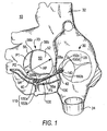
- FIG. 1 is a simplified, substantially horizontal (when the patient is standing), cross sectional view of a patient's heart showing illustrative treatment in accordance with the invention. (Another way to describe this cross section is as substantially parallel to the mitral valve annulus.)
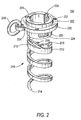
- FIG. 2 is a simplified perspective view of an illustrative embodiment of several representative components of an illustrative prosthesis in accordance with the invention.
- FIG. 3 is a simplified perspective view of an illustrative embodiment of a component of prosthesis delivery and implanting apparatus or instrumentation in accordance with the invention.
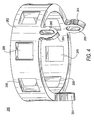
- FIG. 4 is a simplified perspective view of an illustrative embodiment of another component of prosthesis delivery and implanting apparatus in accordance with the invention.
- FIG. 5 is generally similar to FIG. 2, but with the components shown in FIGS. 3 and 4 added.
- FIG. 6 is a simplified perspective view of an illustrative embodiment of another representative component of an illustrative prosthesis in accordance with the invention.
- FIG. 7 is a simplified elevational view of an illustrative embodiment of representative components of an illustrative prosthesis, with illustrative apparatus for delivering and implanting one of those components, all in accordance with the invention.
- FIG. 8 is similar to FIG. 7, but shows a subsequent stage in use of what is shown in FIG. 7 in accordance with the invention.
- FIG. 9 is similar to FIG. 1, but shows an illustrative embodiment of some of the instrumentation that can be used in the implanting of a prosthesis in accordance with the invention.
- FIG. 10 is similar to FIG. 9, but shows a later stage in use of what is shown in FIG. 9 in accordance with the invention. (FIGS. 9 and 10 show all heart structures the same size as FIG. 1. It will be understood, however, that in actual practice the annulus of a patient's mitral valve will typically be larger prior to implanting a prosthesis in accordance with this invention. In other words, in actual practice the mitral valve annulus will be larger in FIGS. 9 and 10 (prior to prosthesis implanting) than in FIG. 1 (after completion of the prosthesis implanting).)
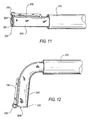
- FIG. 11 is a simplified elevational view of an illustrative embodiment of representative components of an illustrative prosthesis, with illustrative apparatus for delivering and implanting those components, all in accordance with the invention.
- FIG. 12 is similar to FIG. 11, but shows a subsequent stage in use of what is shown in FIG. 11.
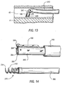
- FIG. 13 is a simplified sectional view of a portion of what is shown in FIGS. 1, 9, and 10 at a particular, relatively early stage in implanting a prosthesis in accordance with the invention.
- FIG. 14 is a simplified perspective view of an illustrative embodiment of representative components of an illustrative prosthesis, with illustrative apparatus for delivering and implanting those components, all in accordance with the invention.
- FIGS. 15-17 are similar to FIG. 13 for successive subsequent stages in implanting a prosthesis in accordance with the invention.
- FIG. 18 is generally similar to FIG. 14, but with certain components additionally assembled in accordance with the invention.
- FIGS. 19-23 are again similar to FIGS. 13 and 15-17, but show successive, more subsequent stages in implanting a prosthesis in accordance with the invention.
- FIG. 24 is a simplified cross sectional view of another portion of what is shown in FIGS. 1, 9, and 10 at a particular intermediate stage in implanting a prosthesis in accordance with the invention.
- FIGS. 25-32 are similar to FIG. 24, but show successive, more subsequent stages in implanting a prosthesis in accordance with the invention.
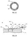
- FIG. 33 is a simplified cross section of an illustrative embodiment of certain components in accordance with the invention.
- FIG. 34 is similar to FIG. 32, but shows another illustrative embodiment of the invention.
- . The invention will first be illustratively described primarily with reference to an embodiment for performing percutaneous mitral valve repair ("PMVR"). Later in this specification examples of possible alternatives to the first-described embodiment will be described, as will examples of some other possible uses of the invention.
- The following features of a patient's
heart 10 are shown in FIG. 1:left atrium 20,right atrium 30,superior vena cava 32,inferior vena cava 34,coronary sinus 40,ostium 42 of coronary sinus 40 (opening into right atrium 30), and mitral valve 50 (includinganterior leaflet 52, posterior leaflet 54 (having three segments P1, P2, and P3),annulus 56,commissures trigones mitral valve 50 is labeled AP. -
Heart 10 is shown in FIG. 1 with aprosthesis 100 implanted in it in accordance with certain aspects of the invention.Prosthesis 100 includes afirst anchor structure 110 that has been implanted incoronary sinus 40 outside posterior mitral valve segment P2.Prosthesis 100 further includes asecond anchor structure 120 that has been implanted inright atrium 30 outside theostium 42 ofcoronary sinus 40.Prosthesis 100 still further includes a linkingmember 130 that extends betweenanchor structures clamp 140 on linkingmember 130 just proximal toanchor structure 140 keepsanchor structures member 130. - Looking more closely at FIG. 1, it will be seen that
anchor structure 110 includes twoscrews member 130 is secured todistal-most screw 150a at or adjacent the head of that screw.Spacer member 160a is disposed around linkingmember 130 immediately proximal to screw 150a. Linkingmember 130 passes through an eyelet (not visible in FIG. 1, but shown in later FIGS.) that is mounted onscrew 150b adjacent its head. The length ofspacer member 160a is approximately equal to the spacing ofscrews member 130.Spacer member 160a can be longer or shorter than is shown in FIG. 1 to provide a favorable angle toscrews -
Anchor structure 120 also includes twoscrews member 130 passes through an eyelet (again, not visible in FIG. 1, but shown in later FIGS.) that is mounted onscrew 150c adjacent its head. Proximal to the eyelet onscrew 150c, linkingmember 130 passes through anotherspacer member 160b, and then through an eyelet onscrew 150d (similar to the eyelet onscrew 150c). Again, the length ofspacer member 160b is approximately equal to the spacing ofscrews member 130. As in the case ofspacer member 160a,spacer member 160b can be longer or shorter than is shown in FIG. 1 to provide a favorable angle toscrews Clamp structure 140 is mounted on linkingmember 130 immediately proximal to the above-mentioned eyelet onproximal-most screw 150d. -
Screws coronary sinus 40 into adjacent heart muscle tissue (preferably in the direction ofmitral valve annulus 56, and even more preferably into tissue of that annulus).Screws right atrium 30. The above-mentioned Hindrichs et al. reference discusses in detail preferred locations of anchor structures likestructures 110 and 120 (although the anchor structures shown herein are new in at least some respects). The Hindrichs et al. reference also discusses tissue structures that anchor structures like 110 and 120 preferably penetrate. All of these principles from the Hindrichs et al. reference are equally applicable to the present invention. - FIG. 1 further shows that the two
screws anchor structure 110 are preferably spaced from one another approximately along the longitudinal axis of linkingmember 130. (This axis may sometimes be referred to herein as the tension axis ofprosthesis 100.) The same is true forscrews screws 150 are preferably driven into tissue transverse to the tension axis. For example, drivingscrews 150 approximately perpendicular to the tension axis is highly desirable but not a requirement for all embodiments of the invention, as long as the screws are transverse to the tension axis to a significant and meaningful degree. - The above-described, pair-wise arrangement of
screws 150, together with the provision of a rigid or substantiallyrigid spacer member 160 between the screws in each pair, provides much stronger and more secure anchoring in tissue than may be achievable, for example, with only a single screw of prior known construction at each oflocations member 130 is attempting to pull the screw more or less straight out of the tissue that it penetrates. Only a relatively small column of tissue is involved in resisting this attempted pull-out of the screw, and such pull-out of a prior known screw may therefore occur. - With the present invention, however, both
screws 150 in each pair of screws tend to remain transverse to the tension axis. For example, thescrew spacer member other screw - Later in this specification it will be pointed out that even single-screw anchor structures employing screw structures of the type shown and described herein tend to be stronger than single-screw anchor structures of prior known construction. Thus the screw structures shown and described herein may be usefully and advantageously employed singly in anchor structures that include only one such screw structure.
- An illustrative embodiment of a
representative screw 150 is shown in more detail in FIG. 2.Screw 150 is actually an assembly of three components: threadedcomponent 210,collar 230, andring 240.Components platinum 10 iridium,platinum 20 iridium, titanium, Nitinol, tantalum, niobium, tungsten, Carpenter CCM, a polymer, another material coated with a polymer, etc. One or more of these components may have drug coating(s) and/or be drug eluting. For radiopacity, one or more of the parts may be plated with a high atomic density material such as gold, platinum, tantalum, or the like. One or more of the components may also be clad with one or more layers, such as stainless steel clad with tantalum metal. - Threaded
component 210 includes hollow, helical, corkscrew-like,screw portion 212 andhollow head portion 220.Screw portion 212 has a sharply pointeddistal tip 214 to facilitate tissue penetration by the screw. Proximal ofdistal tip 214,screw portion 212 has several helical turns that lead back tohead portion 220. These turns may include one ormore barbs 216 to resist unthreading of the screw from tissue into which it has been threaded. In particular, eachbarb 216 is attached to screwportion 212 closer todistal tip 214 and is inclined out and away from the screw portion farther from the distal tip. In other words, eachbarb 216 is anticlinal fromscrew portion 212 in the direction opposite the direction in which the screw portion is driven into tissue. -
Head portion 220 is basically a hollow cylinder with aflange 222 extending radially outwardly from the proximal end of the cylinder. All portions ofscrew component 210 other thanflange 222 are small enough to pass freely throughcollar 230.Flange 222 cannot pass throughcollar 230.Head portion 220 includes features that are usable to releasablyhold screw component 210 on screw driving apparatus (not shown in FIG. 2, but detailed later in this specification). These features comprise three approximately T-shaped cut-outs or recesses 224 inhead portion 220. These recesses are accessible from the hollow interior ofhead portion 220, and they are equidistantly spaced around the circumference of the head portion. -
Collar 230 fits loosely around the outside ofhead portion 220, but, as mentioned earlier,flange 222 is too large to pass through the collar. Accordingly,screw component 210 is rotatable about its longitudinal axis relative tocollar 230, but whenscrew 150 is driven into tissue,collar 230 is trapped or captured on the screw byflange 222.Collar 230 includes features that are usable to releasably hold the collar on apparatus that is used to implantscrew 150 in a patient. These features are recesses orapertures 232 in or throughcollar 230.Collar 230 also has alarger aperture 234 for loosely capturingring 240. -
Ring 240 is large enough for linkingmember 130 to pass freely through the ring. Returning briefly to FIG. 1,ring 240 may be omitted fromdistal-most screw 150a so that the distal end of linkingmember 130 can be attached directly toaperture 232 on thecollar 230 of that screw. For the other screws (150b-d), however, linkingmember 130 preferably passes freely through therings 240 on those screws. - FIG. 3 shows a component of apparatus that can be used for releasably holding and driving a
screw 150 of the type shown in FIG. 2. This screw holder/driver component 250 includes a hollow-cylindricalproximal portion 252 and three distally extending T-shapedportions 254.Proximal portion 252 includes a plurality ofapertures 256 that are usable to help connect screw holder/driver 250 to apparatus components upstream from the holder/driver in a manner that facilitates transmission of torque from those upstream components to holder/driver 250. The component immediately upstream from holder/driver 250 is typically a torqueable flexible shaft (not shown in FIG. 3, but visible in FIG. 14). - T-shaped
portions 254 are shaped, sized, and located to fit somewhat loosely into the T-shaped cut-outs or recesses 224 in thehead portion 220 of ascrew 150. Although not shown in this condition in FIG. 3, T-shapedportions 254 are resiliently biased to deflect radially inwardly toward one another. When thus deflected radially inwardly, the enlarged, distal, free end parts of T-shapedportions 254 can pass freely into or out of the hollowcylindrical head 220 of ascrew 150. However, T-shapedportions 254 can be deflected radially outwardly to the positions shown in FIG. 3 by inserting a properly sized cylindrical member (not shown in FIG. 3) into the interior ofcomponent 250. In this condition, T-shapedportions 254 fit into T-shaped cut-outs or recesses 224 in the head portion of ascrew 150. This both holds the screw tocomponent 250 and allows the screw to be driven by rotatingcomponent 250. When the screw has been driven into tissue to the desired degree, the above-mentioned cylindrical member can be withdrawn from the interior of holder/driven 250. This allows the enlarged distal ends of T-shapedfingers 254 to deflect inwardly and thereby exit from the corresponding portions of T-shapedrecesses 224 in the screw. The screw is therefore no longer held on the apparatus by inter-engagement ofelements - The particular structure shown and described above for releasably holding
screw 150 on holder/driver 250 (e.g., the use of T-shapedportions 254 that are resiliently biased to deflect inwardly) is only one example of many possible ways that this function can be achieved. For example, features like 224 and 254 could have many other complementary shapes that would serve the purposes ofreleasably holding components component 250 tocomponent 150 while those components are held together. The cylindrical member mentioned in the preceding paragraph may be used as a depth gauge for the driving of the associated screw. For example, when the distal end of this cylindrical member reaches the surface of the tissue, it is thereby known that the associated screw has been driven far enough into the tissue. Indeed, the structure may be arranged so that the tissue pushes the cylindrical member out of the screw, thereby decoupling the screw from itsholder 250 and automatically stopping further driving of the screw at the proper depth of tissue penetration. - FIG. 4 shows a component of apparatus that can be used to releasably hold a
screw collar 230 of the type shown in FIG. 2. Thiscollar holder 260 includes a hollow cylindricalproximal portion 262 and three distally extendinggripper fingers 264.Proximal portion 262 can fit concentrically but loosely around the outside of holder/driver 250 (FIG. 3).Proximal portion 262 includes a plurality of apertures 266 that are usable to help connectcollar holder 260 to upstream apparatus components.Fingers 264 fit intoapertures 232 incollar 230. In the radial direction this fit is preferably loose. In the circumferential direction, however, this is a force fit, involving some resilient compression of theapertures 265 throughfingers 264. Acollar 230 can therefore be pressed ontoholder 260, and it will thereafter remain on the holder. However, the collar can be pushed off the holder when the proximal surface of the threadedportion 210 associated with that collar is pushed distally with sufficient force. Alternatively, a separate catheter-like pusher could be used to pushcollar 230 offholder 260. - FIG. 5 shows an assembly of the elements that are shown individually in FIGS. 2-4.
Screw component 210 is releasably retained on holder/driver component 250 by the presence of T-shapedportions 254 ofcomponent 250 incomplementary recesses 224 in thehead portion 220 ofscrew portion 210. The presence of T-shapedportions 254 inrecesses 224 also makes it possible to rotatescrew component 210 about its longitudinal axis by rotating holder/driver component 250 about that axis.Collar 230 is releasably retained oncollar holder 260 by the force-fitted presence offingers 264 fromholder 260 incollar apertures 232.Components components component 210. FIG. 5 omits the apparatus component that is required to keep T-shapedportions 254 deflected radially outward and therefore inrecesses 224 as shown in FIG. 5. Note that the free ends offingers 264 preferably extend completely through and beyond the lower surface ofcollar 230. This permits the free ends offingers 264 to engage or penetrate the surface of the tissue into which threadedportion 210 is going to be driven. Such engagement or penetration helps to stabilize the assembly at a desired location on the surface of the tissue during driving of threadedportion 210, and also preventscollar 230 from undesirably rotating with threadedportion 210 as the threaded portion is rotated to drive it into the tissue. - Again, the particular structures shown in the FIGS. described thus far for releasably holding
collar 230 onholder 260 are only illustrative, and any of many other structures can be used for this purpose instead if desired. For example, more positive threaded or bayonet-type structures can be used instead of the above-mentioned force-fit connection. - Further components of the illustrative prosthesis being described are
spacer members typical spacer member 160 in more detail. As shown in this FIG., aspacer member 160 can be a hollow cylinder (e.g., of a bio-compatible metal). The hollow center ofspacer member 160 is preferably large enough to allow the spacer member to slide freely along the length of linkingmember 130. However, the diameter ofspacer member 160 should be large enough so that the ends of the spacer member can engage the head portions ofscrews 150 that the spacer member abuts. -
Spacer member 160 may have features beyond those shown in FIG. 6. For example,spacer member 160 may have perforations, a dacron cover, and/or other features to promote tissue in-growth and anchoring in the patient. Suitable materials for spacer member 1.60 include those mentioned above forcomponents - Still another component of the apparatus is
clamp structure 140. An illustrative embodiment ofclamp structure 140 is shown in FIGS. 7 and 8, with some other apparatus also visible. In FIG. 7 clamp structure is disposed concentrically around ahollow tube 270 through which linkingmember 130 passes loosely. In FIG. 8tube 270 has been removed to release clampingstructure 140 to engage linkingmember 130. Note that the distal direction is to the left in FIGS. 7 and 8. This is consistent with FIG. 1. - Clamp structure 140 (e.g., of bio-compatible metal) is resiliently biased to assume the shape shown in FIG. 8, but it can be elastically deflected to the shape shown in FIG. 7. (Alternatively clamping
structure 140 could be plastically deformed from the shape shown in FIG. 7 to the shape shown in FIG. 8.) Proceeding from left to right in FIG. 7,clamp structure 140 includes (1) a hollowcylindrical portion 142, (2) a plurality of relativelyshort fingers 144 that extend in the proximal direction fromcylindrical portion 142 and that are resiliently biased to deflect inwardly, and a (3) plurality of relativelylong fingers 146 that also extend in the proximal direction fromcylindrical portion 142 and that are intercalated withfingers 144. Proximal free end portions offingers 146 are also resiliently biased to deflect inwardly. The inward bias offingers clamp structure 140 ontube 270, albeit in such a way thattube 270 can be withdrawn fromstructure 140 when desired. - The proximally directed free ends of
fingers 144 are preferably sharp.enough to dig into linkingmember 130 whentube 270 is withdrawn from inside structure 140 (see FIG. 8). This preventsclamp structure 140 from moving proximally along linkingmember 130 oncestructure 140 has thus engagedmember 130. This resistance to movement ofstructure 140 may be facilitated or enhanced by making linkingmember 130 of braided suture material as shown in FIGS. 7 and 8, but other constructions of linkingmember 130 are also possible, as will be further discussed later in this specification. - The proximally directed free ends of
fingers 146 are less sharp and are intended to press inwardly on linkingmember 130 for such purposes as to stabilizeclamp structure 140 on linking member and to prevent abraided linking member 130 from unraveling when it is subsequently cut proximal to clampstructure 140. - Having described an illustrative embodiment of a
prosthesis 100 in accordance with the invention, we turn now to a description of illustrative methods and apparatus for implanting such a prosthesis, also in accordance with the invention. The illustrative methods and apparatus that will first be described are percutaneous. - An illustrative method begins with inserting an
introducer tube 300 into thesuperior vena cava 32 of the patient as shown in FIG. 9. This may be done by starting from an introduction point into the patient along the patient's jugular vein. A possible alternative approach is viainferior vena cava 34. Either of these approaches gives access toright atrium 30. Although the distal end ofintroducer 300 is shown relatively low in FIG. 9, it may actually be higher and therefore out of sight in what is shown in that FIG. - The next step in the illustrative method being discussed is to insert a guide catheter or
sheath 310 into the patient viaintroducer 300 and to extend that guide catheter into theostium 42 ofcoronary sinus 40 as is also shown in FIG. 9. - The next step is to extend an obturator or
dilator 320 and awire 330 intoguide catheter 310 and then from the distal end of the guide catheter farther into coronary sinus 40 (continue to see FIG. 9).Obturator 320 provides support forwire 330 to help the distal-most portion of the wire extend intocoronary sinus 40, and possibly into a tributary thereof, well beyond the point at which thedistal anchor structure 110 ofprosthesis 100 will be implanted. - The next step (illustrated by FIG. 10) is to advance
guide catheter 310 to the desired location ofdistal anchor structure 110.Obturator 320 is removed at this time. - The next step is to introduce into
guide catheter 310 and "over" wire 330 a delivery system for the first part ofdistal anchor structure 110. In particular, this is a delivery system for implantingscrew 150a. FIG. 11 shows a first part of this delivery system extending from the distal end ofguide catheter 310. For clarity, no tissue is shown in FIG. 11. This FIG also omitswire 330, although it will be understood that inactual use wire 330 may be present. The portion of the delivery system shown in FIG. 11 includestubular member 340 extending from the distal end ofguide catheter 310. A collar holder 260 (not visible in FIG. 11) is secured inside the distal end oftubular member 340, and acollar 230 is removably mounted on the distally extendinggripper fingers 264 of that collar holder in the manner described earlier in this specification. The distal end of linking member 130 (which extends from aside lumen 341 of tubular member 340 (see FIG. 33)) is secured to ring 240 oncollar 230. Alternatively,ring 240 could be omitted, and the distal end of linkingmember 130 could be secured directly to theaperture 234 incollar 230 that ring 240 is shown passing through. A proximal portion of linkingstructure 130 preferably passes along theside lumen 341 oftubular member 340 upstream from what is shown in FIG. 11 to help ensure that linkingmember 130 does not become undesirably wrapped around other components of the apparatus (see again FIG. 33). Wire 330 (not shown in FIG. 11) can extend from the distal end of the assembly ofelements 340/260/230 to its distal end to the left of what is shown in FIG. 11.Wire 330 can be withdrawn once the elements shown in FIG. 11 have reached the desired location along coronary sinus 40 (or the wire could be withdrawn earlier, e.g., after the distal end ofguide catheter 310 has reached its desired location alongcoronary sinus 40 as shown in FIG. 10). - The distal portion of
tubular member 340 is "steerable" (see FIG. 12). This means that the distal portion oftubular member 340 can be controllably deflected transverse to the longitudinal axis of guide catheter 310 (or to the longitudinal axis of the proximally adjacent portion of tubular member 340). The amount of this deflection is preferably up to about 90° or more. In other words, the distal portion oftubular member 340 can be deflected so that it becomes substantially perpendicular to the proximally adjacent portion of that member. This allows the distal portion oftubular member 340 to be aimed at the side wall ofcoronary sinus 40 as shown in FIG. 13. Indeed, it may be desirable to aim the distal end of tubular member 340 (and therefore collar 230) at a particular portion of the circumference ofcoronary sinus 40 in order to get good anchoring of the anchor structure to be implanted in the strongest possible tissue of the heart (see the above-mentioned Hindrichs et al. reference, which discusses optimal placement of anchor structures in the coronary sinus and elsewhere in the heart). The steerability oftubular member 340 may be unidirectional, bidirectional, or multidirectional (in other words, in one direction transverse to the longitudinal axis of the remainder of the structure, in either of two directions transverse to that longitudinal axis, or in any one of several directions transverse to that longitudinal axis). - Although not shown in FIG. 13, the relative sizes and shapes of the tissue and apparatus components may be such that transverse deflection of the distal portion of the structure causes a substantial distortion of
coronary sinus 40 at that location. In particular, the "back" side of the apparatus (i.e., adjacent the bend in tubular member 340) may deflect the adjacent portion ofcoronary sinus 40 outwardly. This helps to pushcollar 230 firmly against the opposite side of the coronary sinus, which facilitates driving the threadedportion 210 of a screw into the tissue as described below. (The same kind of distortion ofcoronary sinus 40 may occur in connection with FIG. 19, although this distortion is again not actually shown in that FIG.) - Further components of the delivery system for implanting
screw 150a are shown in FIG. 14. These components includetubular member 350 with a screw holder/driver attached to its distal end and threadedcomponent 210 held on that holder/driver. Another tube or plug (not visible) is disposed coaxially insideelements portions 254 of holder/driver 250 deflected radially outward in thecomplementary recesses 224 in threadedcomponent 210 and thereby hold threadedcomponent 210 on holder/driver 250. -
Components 350/250/210 are insertable coaxially into and alongtubular member 340 from the proximal end ofmember 340.Components 350/250/210 may be insidemember 340 whenmember 340 is inserted intoguide catheter 310. When the distal portion ofmember 340 is properly aimed toward the side wall ofcoronary sinus 40 as shown in FIG. 13,tubular member 350 may be pushed distally and rotated about its longitudinal axis to cause threadedportion 210 to begin to emerge from the distal end ofassembly 340/260/230 and to begin to threadedly penetrate the side wall ofcoronary sinus 40 and adjacent heart tissue 41 (see FIG. 15). Note again thatcomponents 310 and/or 340 preferably bear on the wall ofcoronary sinus 40 approximately opposite the tissue-entry point of threadedportion 210 to help force threadedportion 210 into the tissue.Component 350 is preferably sufficiently laterally flexile to follow the lateral (steering) deflection ofcomponent 340.Component 350 is also able to transmit tocomponent 210 the torque necessary tothread component 210 into tissue. - When threaded
portion 210 has been driven sufficiently far intotissue 40/41 so that flange 222 (e.g., FIG. 2)contacts collar 230 and the collar is at least in contact withtissue 40/41, driving of threadedportion 210 is stopped. The next step is to retract the above-mentioned tube or plug from inside screw holder/driver 250. This allows T-shapedportions 254 of holder/driver 250 to deflect radially inwardly, which releases threadedportion 210 from holder/driver 250. To also releasecollar 230 fromcollar holder 260,tubular member 350 is pushed distally whiletubular member 340 is pulled proximally.
Alternatively, only one ofmembers collar 230 off thegripper fingers 264 ofcollar holder 260.
Screw 150a is now implanted intissue 40/41 and fully released fromdelivery apparatus 340/260/350/250, although the screw is still attached to the distal end of linkingmember 130. - The next step is to re-straighten the steerable distal portion of
tubular member 340 and withdrawcomponents - The next step is to push
spacer member 160a into the patient over linkingmember 130. A proximal portion of linkingmember 130 may transition from a suture-like material to a wire to facilitate gettingspacer member 160a (and other apparatus) into the patient over linkingmember 130. Atubular pusher 370 may be placed over linkingmember 130 proximal tospacer member 160a for use in pushingspacer member 160a into the patient and into abutment withscrew 150a as shown in FIG. 17. - After
spacer member 160a is in place,tubular pusher 370 may be withdrawn from the patient. - The next step is to position the distal end of
guide catheter 310 appropriately for implantingsecond screw 150b. Apparatus for deliveringsecond screw 150b can then be inserted into the patient viaguide catheter 310. The delivery system forsecond screw 150b can be very similar to the above-described delivery system forfirst screw 150a. The only significant difference is that in the case ofsecond screw 150b linking member 130 passes loosely through thering 240 of the second screw rather than being secured to the screw as in the case offirst screw 150a. FIG. 18 illustrates this type of loose passage of linkingmember 130 through aring 240 on ascrew 150 likescrew 150b. - Because the delivery system for
screw 150b can be so similar to the delivery system forscrew 150a, the same reference numbers will be used again (but with a "b" suffix) for components of the second screw delivery system. Discussion of delivery and implanting of the second screw can also be somewhat abbreviated because it is so similar to the above-described delivery and implanting of the first screw. - FIG. 19 shows the condition of the apparatus after
components second screw 150b have been extended from the distal end ofguide catheter 310 and steered (i.e., laterally deflected) toward the desired point on the side wall ofcoronary sinus 40. Note the passage of linkingmember 130 throughring 240b on thecollar 230b that will form part ofsecond screw 150b. Passage of linkingmember 130 throughring 240b is facilitated by the above-mentioned proximal wire end portion of linkingmember 130, which remains outside the patients body and is available for use in helping to place successive components and instrumentalities on linkingmember 130. - After the condition shown in FIG. 19 is attained, the threaded
portion 210b ofsecond screw 150b can be advanced distally throughassembly 340b/260b/230b and driven intotissue 40/41 as described above for the corresponding components associated withscrew 150a (see FIG. 20). - After threaded
portion 210b has been driven intotissue 40/41, threadedportion 210b can be released from its holder/driver (not visible, but insidetubular member 340b) as described earlier for the corresponding parts associated withscrew 150a. Thencollar 230b can be released from itsholder 260b in the same manner as described above for the corresponding parts associated withscrew 150a. The distal end oftubular member 340b can be re-straightened, and all of the delivery apparatus forscrew 150b can be proximally withdrawn from the patient viaguide catheter 310. The condition of the apparatus is now as shown in FIG. 21. - Although perhaps not necessary, a
clamp structure 140a can now be put on linkingmember 130 immediately proximal to screw 150b. This optional process is shown in FIGS. 22 and 23. In FIG. 22clamp structure 140a and associated delivery apparatus (e.g., as shown in more detail in FIG. 7) is loaded onto linkingmember 130 and introduced into the patient viaguide catheter 310. The delivery apparatus forclamp 140a includes atube 270 inside the clamp (see FIG. 7) and anothertubular member 380 disposed concentrically around the outside oftube 270 and bearing (at its distal end) on the proximal end of the clamp. FIG. 22 shows clamp 140a pushed up against structure ofscrew 150b and therefore ready for release onto linkingmember 130. -
Clamp 140a is released onto linkingmember 130 by pulling back ontube 270 while holdingtubular member 380 stationary (see also FIG. 8). Proximal withdrawal oftube 270 allows thevarious fingers member 130 as described earlier in connection with FIG. 8.Tubes clamp 140a pressing distally on the structure ofproximal screw 150b may help to stiffen and strengthen distal anchor structure 110 (includingscrews clamp 160a is optional. - The next step is to retract
guide catheter 310 into the patient's right atrium 30 (see FIG. 24). The distal end ofguide catheter 310 is placed near the desired location ofthird screw 150c. Delivery and implanting ofthird screw 150c can be similar (except for location) to delivery and implanting ofsecond screw 150b. Accordingly, the description forthird screw 150c can be somewhat abbreviated. - FIG. 24 shows the apparatus after the distal end of the delivery system for
third screw 150c has been steered (deflected laterally) toward the desired implant site forscrew 150c in thetissue 31 ofright atrium 30. Once again, the above-mentioned Hindrichs et al. reference discusses preferred locations for a proximal tissue anchor. The proximal anchor placement principles discussed there are equally applicable to placingscrew 150c in accordance with this invention. Those principles are preferably followed in locating and implantingscrew 150c (andscrew 150d) in practicing the present invention. As shown in FIG. 24,delivery system components third screw 150c position thecollar 230c for the third screw against the surface ofheart tissue 31 at the desired location. Linkingmember 130 comes from above-described distal anchor 110 (out of sight to the left in FIG. 24), passes through thering 240c oncollar 230c, and enterstubular member 340c. - If desired, the steering deflection of
tubular member 340c can be passive deflection (i.e., a shape that is remembered bymember 340c once that member is out of guide catheter 310). Incoronary sinus 40 pull wires may be needed to generate more deflecting force and deform the coronary sinus. But inright atrium 30 tissue deformation may not be involved, and so passive steering deflection oftubular member 340c may be sufficient. (The same may be true fortubular member 340d, described below.) - After
collar 230c has been positioned as desired, the threadedportion 210c of that screw is driven (by other delivery system components that areinside components components 350 and 250 (FIG. 14)) throughcollar 230c and intotissue 31 as shown in FIG. 25. Threadedportion 210c is then released from its holder/driver,collar 230c is released from itsholder 260c, and the delivery system forscrew 150c is re-straightened and withdrawn from the patient viaguide catheter 310. The condition of the apparatus is now as shown in FIG. 26. - The next step is to insert
spacer 160b into the patient along linkingmember 130 until it abuts the proximal side ofscrew 150c. This step is so similar to the insertion of spacer 160a that it does not need to be separately illustrated or further described. - The next step is to reposition the distal end of
guide catheter 310 for implanting offourth screw 150d. Then the fourth screw and its delivery system are inserted intoguide catheter 310 over linkingmember 130. The distal end of thedelivery system 340d forfourth screw 150d is then steered towardtissue 31 just proximal to screw 150c andspacer 160b as shown in FIG. 27. Again, this steering may be passive as in the case ofdelivery system 340c. - The next step, illustrated by FIG. 28, is to drive the threaded
portion 210d ofscrew 150d throughcollar 230d and intotissue 31. Thereafter, threadedportion 210d is released from its holder/driver apparatus (not visible, but similar to previously shown and described components of the same kind), andcollar 230d is released from itsholder 260d.Delivery system 340d is then re-straightened and withdrawn from the patient viaguide catheter 310. The condition of the apparatus is now as shown in FIG. 29. - The next step is to introduce a
second clamp 140b into the patient on secondclamp delivery apparatus 380b (see FIG. 30). This is again done viaguide catheter 310 and with all ofelements member 130 that is proximal toproximal anchor structure 120. Whenclamp 140b reachesproximal anchor structure 120, linkingstructure 130 andstructure 140b/380b can be used to shorten the distance betweenanchor structures components 140b/380b (also from outside the patient). - When the desired reduced spacing between
anchor structures clamp 140b is mounted is pulled proximally (while maintaining the relative positions ofelements clamp 140b to grip linkingmember 130 and thereby fix the desired spacing betweenanchor structures member 130 and compression onstructure 380b can therefore be released, and the delivery apparatus forclamp 140b can be withdrawn from the patient. The condition of the apparatus is now as shown in FIG. 31. - It should be noted that the amount of spacing between distal and
proximal anchor structures clamp 140b is launched. This means that different spacings can be tried until the best spacing is found. Even if the spacing is initially decreased too much, that can be reversed by allowing the spacing to increase again.Clamp 140b is launched only after the best spacing has been found. It should also be noted that in this embodiment the spacing betweenanchor structures anchor structures - The preceding paragraph refers to the possibility of trying different spacings of
anchor structures - After
clamp 140b has been launched, the next step is to cut linkingstructure 130 proximal to clamp 140b and to remove everything that is proximal to the cut. The condition of the apparatus is now as shown in FIG. 32 (and also FIG. 1). The process of implanting the prosthesis is complete and all delivery apparatus can be withdrawn from the patient. - A possible variation on the above method is to install the prosthesis as described above with little or no significant shortening of the distance between
anchor structures - Another possible variation on the above-described methods and apparatus is illustrated by FIG. 34. In this embodiment the prosthesis is implanted as described above (with or without shortening of the distance between
anchor structures 110 and 120). Some of linkingmember 130 is left proximal to clamp 140b. At any time after the prosthesis has been implanted in the patient (e.g., several weeks, months, or even years after implanting of the prosthesis), the patient can be re-entered to change or further change the spacing betweenanchor structures catheter 410, which can be introduced into the patient percutaneously in the same way that other apparatus described above can be introduced.Catheter 410 is used to deliversnare structure 420/430 into the patient adjacent to the proximal end of linkingmember 130.Snare loop 430 is deployed and snares the proximal end of linkingmember 130. Linkingmember 130 may have been left with aproximal enlargement 132 to facilitate good engagement bysnare loop 430.Enlargement 132 may be radio-opaque to facilitate finding it in the patient.Snare loop 430 is used to hold the end of linkingstructure 130 whilesnare tube 420 is pushed distally onto linkingstructure 130. When the distal end ofsnare tube 420 reaches clamp 160b,snare tube 420 can be used to push that clamp distally along linkingmember 130, whilesnare loop 430 is pulled proximally to hold linkingmember 130 in place. In this way the distance betweenanchor structures member 130 can be released fromsnare loop 430 andapparatus 410/420/430 can be withdrawn from the patient.Clamp 140b will maintain the prosthesis with whatever spacing has been set betweenanchor structures - Embodiments of the type illustrated by FIG. 34 may be desirable because they can take advantage of the fact that
anchor structures anchor structures member 130. There is therefore little or no force acting on the anchor structures that might tend to pull them from the tissue. After the tissue has healed, the anchor structures are stronger than they are when first implanted. The technique and apparatus illustrated by FIG. 34 can then be used totension linking member 130 and shorten the distance betweenanchor structures - It will be understood that the foregoing is only illustrative of the principles of the invention, and that various modifications can be made by those skilled in the art without departing from the scope and spirit of the invention. For example, use of
clamp structure 140a (FIGS. 22 and 23) is optional, and that structure can be omitted from the prosthesis if desired. As another example of a possible modification, eachscrew 210 could be held on itsholder 250 by structures 254 (FIG. 3) that are resiliently biased to deflect outwardly rather than inwardly as described above. Each ring 240 (e.g., FIG. 2) could be integrated into the associatedcollar 230 rather than being a separate component. Each ofanchor structures anchor structures member 130 can be or can be part of an electrical conductor that is electrically connected to the tissue-piercing lead. This conductor can extend to other electrical apparatus inside and/or outside the patient. Any portion or portions of the prosthesis can have one or more coatings for biological purposes such as to reduce inflammatory response, promote healing, reduce clotting or thrombogenicity response, etc. For example, this may be accomplished by using one or more polymer coatings that can elute one or more drugs or medications. Linkingmember 130 can have radio-opaque markers at predetermined spacings or locations to help visualize the amount of shortening betweenanchor structures - As is mentioned earlier in this specification, screw
structures 150 of the types shown and described herein have features that may permit effective use of only one such screw (rather than a pair) as an anchor structure such as 110 and/or 120 in a prosthesis in accordance with this invention. For example,collar 230 may act as a washer that bears on the surface of tissue and helps to reduce tipping of asingle screw structure 150 when that structure is pulled on by the linkingmember 130 of a prosthesis. Similarly, the fact that the point of attachment of linkingmember 130 to screwstructure 150 is on collar 230 (which is at or close to the tissue surface rather than at the top of the screw structure) and off the central longitudinal axis ofscrew structure 150 may further help to reduce tipping of a single screw structure when pulled by the linking member. As is explained earlier in this specification, a screw that can remain transverse to the direction of pull tends to resist pulling out of tissue better than a screw that can tip over and become aligned with the direction of pull. Thus the above-mentioned features that help even a single screw structure of this invention resist tipping over make such a screw structure a better, stronger anchor structure even when used alone and without a second screw in a tandem pair. - Although the invention has been illustrated for the most part in the context of percutaneous mitral valve repair, it has also been mentioned that aspects of the invention are alternatively usable non-percutaneously and/or for other types of prostheses. The above-mentioned Hindrichs et al. reference shows and describes several examples of such other contexts, and it will be apparent from what has been said above how features of the present invention can be employed in those contexts.
Claims (53)
- A prosthesis for reducing distance between first and second portions of soft body tissue structure comprising:a first anchor structure including first and second screw structures threaded into the first portion of the tissue structure with a first spacer structure for maintaining a space between the first and second screw structures;a second anchor structure including third and fourth screw structures threaded into the second portion of the tissue structure with a second spacer structure for maintaining a space between the third and fourth screw structures; andlinking structure between the first and second anchor structures.
- The prosthesis defined in claim 1 wherein the first and second screw structures are threaded into the first portion of the tissue structure transverse to a longitudinal axis of an adjacent portion of the linking structure.
- The prosthesis defined in claim 2 wherein the third and fourth screw structures are threaded into the second portion of the tissue structure transverse to a longitudinal axis of an adjacent portion of the linking structure.
- The prosthesis defined in claim 1,2 or 3 further comprising means for maintaining a selectable length of the linking structure between the first and second anchor structures.
- The prosthesis defined in claim 1,2,3 or 4 wherein at least one of the screw structures comprises:an annular collar; anda screw member having a threaded portion that can pass through the collar and a head portion that is too large to pass through the collar.
- The prosthesis defined in claim 5 wherein the head portion traps the collar against tissue into which the threaded portion is threaded.
- The prosthesis defined in claim 6 wherein the collar includes structure for engaging the linking structure.
- The prosthesis defined in claim 7 wherein the structure for engaging holds the collar at a fixed location on the linking structure.
- The prosthesis defined in claim 7 or 8 wherein the structure for engaging allows the collar to slide along the linking structure.
- The prosthesis defined in any one of claims 1 to 9 wherein the first spacer structure is slidable along the linking structure.
- The prosthesis defined in claim 10 wherein the second spacer structure is slidable along the linking member.
- The prosthesis defined in any one of claims 4 to 11 wherein the means for maintaining comprises:a clamp structure for selectively clamping onto the linking structure.
- The prosthesis defined in claim 12 wherein the clamp structure clamps the linking structure adjacent to the fourth screw structure.
- The prosthesis defined in any one of claims 1 to 13 wherein the linking structure is flexible.
- The prosthesis defined in any one of claims 4 to 14 wherein the means for maintaining is deployable to select and maintain any length of the linking structure between the first and second anchor structures within a range of such lengths.
- The prosthesis defined in claim 15 wherein the means for maintaining has a pre-deployment state in which it permits the length of the linking structure between the first and second anchor structures to be increased or deceased.
- The prosthesis defined in any one of claims 4 to 16 wherein the means for maintaining is operable to select and maintain a first selectable length of the linking structure between the first and second anchor structures, and to subsequently select and maintain a second selectable length of the linking structure between the first and second anchor structures, the second selectable length being less than the first selectable length.
- A method of reducing distance between first and second portions of soft body tissue comprising:threading a first screw structure into the first portion of the tissue structure, the first screw structure having linking structure attached thereto;disposing a first spacer structure on the linking structure adjacent to the first screw structure;threading a second screw structure into the first portion of the tissue structure spaced from the first screw structure by the first spacer structure, the second screw structure being slidable along the linking structure;threading a third screw structure into the second portion of the tissue structure, the third screw structure being slidable along the linking structure;disposing a second spacer structure on the linking structure adjacent to the third screw structure;threading a fourth screw structure into the second portion of the tissue structure spaced from the third screw structure by the second spacer structure, the fourth screw structure being slidable along the linking structure;sliding the third and fourth screw structures and the second spacer structure along the linking member toward the first and second screw structures and the first spacer structure to reduce the distance between the first and second portions of the tissue structure; andpreventing the third and fourth screw structure and the second spacer structure from sliding back along the linking member.
- The method defined in claim 18 wherein the first and second screw structures are threaded into the first portion of the tissue structure transverse to a longitudinal axis of an adjacent portion of the linking structure.
- The method defined in claim 19 wherein the third and fourth screw structures are threaded into the second portion of the tissue structure transverse to a longitudinal axis of an adjacent portion of the linking structure.
- The method defined in claim 18, 19 or 20, wherein the preventing comprises:applying a clamp structure to the linking structure adjacent the fourth screw structure.
- The method defined in claim 18, 19, 20 or 21, wherein the first and second portions of the tissue structure are internal to a patient, and wherein the method is performed percutaneously.
- The method defined in claim 22 wherein the first and second portions of the tissue structure are adjacent to the patient's mitral valve annulus at respective first and second locations that are spaced from one another along that annulus.
- The method defined in claim 23 wherein the first location is accessed from the patient's coronary sinus.
- The method defined in claim 24 wherein the second location is accessed from the patient's right atrium.
- The method defined in claim 24 or 25 wherein the threading of the first and second screw structures is performed from instrumentation that is inserted percutaneously into the patient's coronary sinus.
- The method defined in claim 25 or 26 wherein the threading of the third and fourth screw structures is performed from instrumentation that is inserted percutaneously into the patient's right atrium.
- The method defined in claim 26 or 27 wherein the threading of the first and second screw structures is performed transversely to a longitudinal axis of an adjacent portion of the patient's coronary sinus.
- The method defined in claim 27 or 28 wherein the threading of the third and fourth screw structures is performed transversely to an adjacent surface portion of the patient's right atrium.
- Instrumentation for percutaneously implanting a screw structure in soft body tissue structure comprising:a first elongated hollow structure for releasably holding a collar structure adjacent a distal end of the first structure; anda second elongated structure disposed in the first hollow structure for releasably holding a threaded structure adjacent a distal end of the second structure, the threaded structure having a distal threaded portion that can pass through the collar structure and a proximal head portion that cannot pass through the collar structure, the second structure being movable axially along the first hollow structure and rotatable relative to the first hollow structure about a longitudinal axis of the second structure.
- The instrumentation defined in claim 30 wherein a distal portion of the first structure is selectively steerable transverse to a longitudinal axis of an adjacent portion of that structure.
- The instrumentation defined in claim 31 wherein a distal portion of the second structure is sufficiently laterally flexible to permit that portion of the second structure to follow transverse steering of the first structure.
- The instrumentation defined in claim 30, 31 or 32 wherein the second structure is able to transmit torque along its length to thread the second structure into tissue.
- The instrumentation defined in claim 30, 31, 32 or 33 further comprising:an elongated linking structure attached to the collar structure.
- The instrumentation defined in any one of claims 30 to 34 wherein the collar structure is slidable along an elongated linking structure.
- The instrumentation defined in claim 35 wherein at least part of the linking structure extends along the second structure outside of that structure.
- The instrumentation defined in claim 36 wherein the first structure includes a side lumen along which at least part of the linking structure extends.
- The instrumentation defined in claim 37 wherein the linking structure is slidable along the side lumen.
- The instrumentation defined in any one of claims 34 to 38 further comprising:a third elongated structure for pushing a spacer member along the linking structure to the collar structure.
- The instrumentation defined in any one of claims 34 to 39 further comprising:a third elongated structure for delivering a clamp structure to a desired location along the linking structure.
- The instrumentation defined in claim 40 wherein the third elongated structure is selectively operable to release the clamp structure onto the linking structure so that the clamp structure can clamp the linking structure at the desired location.
- A prosthesis for maintaining distance between first and second portions of soft body tissue structure comprising:a first anchor structure including first and second screw structures threaded into the first portion of the tissue structure with a first spacer structure for maintaining a space between the first and second screw structures;a second anchor structure including third and fourth screw structures threaded into the second portion of the tissue structure with a second spacer structure for maintaining a space between the third and fourth screw structures; andlinking structure between the first and second anchor structures.
- The prosthesis defined in claimed 42 further comprising means for maintaining a selectable length of the linking structure between the first and second anchor structures.
- The prosthesis defined in claim 43 wherein the means for maintaining is operable to select and maintain a first selectable length of the linking structure between the first and second anchor structures, and to subsequently select and maintain a second selectable length of the linking structure between the first and second anchor structures, the second selectable length being less than the first selectable length.
- A method of reducing distance between first and second portions of soft body tissue structure comprising:implanting a first anchor structure in the first portion of the body tissue structure;implanting a second anchor structure in the second portion of the body tissue structure;providing a linking structure between the first and second anchor structures;waiting for at least some healing of the first and second portions of the body tissue structure; andreducing length of the linking structure between the first and second anchor structures to reduce the distance between the first and second portions of the body tissue structure.
- A screw structure for use as an anchor in soft body tissue comprising:a threaded component having a head portion and a threaded portion that extends away from the head portion; anda collar component disposed annularly around the head portion, the collar component being rotatable around the head portion but not removable from the head portion in a direction away from the threaded portion.
- The screw structure defined in claim 46 wherein the collar component is adapted for attachment to a tether structure.
- The screw structure defined in claim 46 or 47 wherein the threaded portion is sized to pass freely through the collar component.
- The screw structure defined in claim 46, 47 or 48 wherein the threaded component comprises a hollow annular structure substantially concentric with the collar component.
- The screw structure defined in claim 46, 47, 48 or 49 further comprising:a ring member that passes loosely through an aperture in the collar component.
- The screw structure defined in claim 50 wherein the ring member is adapted for attachment to a tether structure.
- The screw structure defined in claim 50 wherein the ring member is adapted for sliding along a tether structure that passes through the ring member.
- The screw structure defined in any one of claims 46 to 52 wherein the threaded portion includes barbs that are inclined to resist unthreading of the threaded portion from tissue into which the threaded portion has been threaded.
Applications Claiming Priority (1)
| Application Number | Priority Date | Filing Date | Title |
|---|---|---|---|
| US11/215,341 US9492277B2 (en) | 2005-08-30 | 2005-08-30 | Soft body tissue remodeling methods and apparatus |
Publications (3)
| Publication Number | Publication Date |
|---|---|
| EP1759663A2 true EP1759663A2 (en) | 2007-03-07 |
| EP1759663A3 EP1759663A3 (en) | 2007-04-25 |
| EP1759663B1 EP1759663B1 (en) | 2009-12-16 |
Family
ID=37433689
Family Applications (1)
| Application Number | Title | Priority Date | Filing Date |
|---|---|---|---|
| EP06016818A Not-in-force EP1759663B1 (en) | 2005-08-30 | 2006-08-11 | Soft body tissue remodeling apparatus |
Country Status (4)
| Country | Link |
|---|---|
| US (1) | US9492277B2 (en) |
| EP (1) | EP1759663B1 (en) |
| AT (1) | ATE451892T1 (en) |
| DE (1) | DE602006011092D1 (en) |
Cited By (19)
| Publication number | Priority date | Publication date | Assignee | Title |
|---|---|---|---|---|
| WO2012135045A1 (en) * | 2011-03-25 | 2012-10-04 | Smith & Nephew, Inc. | Tissue lifting |
| WO2013103796A1 (en) * | 2012-01-05 | 2013-07-11 | Cook Medical Technologies Llc | Attachment device for tissue approximation and retraction |
| WO2014108903A1 (en) * | 2013-01-09 | 2014-07-17 | 4Tech Inc. | Soft tissue anchors |
| US8961596B2 (en) | 2010-01-22 | 2015-02-24 | 4Tech Inc. | Method and apparatus for tricuspid valve repair using tension |
| US8961594B2 (en) | 2012-05-31 | 2015-02-24 | 4Tech Inc. | Heart valve repair system |
| EP2525741A4 (en) * | 2010-01-22 | 2015-05-06 | 4Tech Inc | Tricuspid valve repair using tension |
| US9241702B2 (en) | 2010-01-22 | 2016-01-26 | 4Tech Inc. | Method and apparatus for tricuspid valve repair using tension |
| US9307980B2 (en) | 2010-01-22 | 2016-04-12 | 4Tech Inc. | Tricuspid valve repair using tension |
| US9801720B2 (en) | 2014-06-19 | 2017-10-31 | 4Tech Inc. | Cardiac tissue cinching |
| US9907681B2 (en) | 2013-03-14 | 2018-03-06 | 4Tech Inc. | Stent with tether interface |
| US9907547B2 (en) | 2014-12-02 | 2018-03-06 | 4Tech Inc. | Off-center tissue anchors |
| US10022114B2 (en) | 2013-10-30 | 2018-07-17 | 4Tech Inc. | Percutaneous tether locking |
| US10039643B2 (en) | 2013-10-30 | 2018-08-07 | 4Tech Inc. | Multiple anchoring-point tension system |
| US10052095B2 (en) | 2013-10-30 | 2018-08-21 | 4Tech Inc. | Multiple anchoring-point tension system |
| US10058323B2 (en) | 2010-01-22 | 2018-08-28 | 4 Tech Inc. | Tricuspid valve repair using tension |
| US10806579B2 (en) | 2017-10-20 | 2020-10-20 | Boston Scientific Scimed, Inc. | Heart valve repair implant for treating tricuspid regurgitation |
| WO2021026068A1 (en) * | 2019-08-02 | 2021-02-11 | Boston Scientific Scimed, Inc. | Anchor designs configured for anchor migration/ backout control |
| WO2022172149A1 (en) * | 2021-02-09 | 2022-08-18 | Edwards Lifesciences Innovation (Israel) Ltd. | Tissue anchors and techniques for use therewith |
| US11857417B2 (en) | 2020-08-16 | 2024-01-02 | Trilio Medical Ltd. | Leaflet support |
Families Citing this family (135)
| Publication number | Priority date | Publication date | Assignee | Title |
|---|---|---|---|---|
| US7753922B2 (en) * | 2003-09-04 | 2010-07-13 | Guided Delivery Systems, Inc. | Devices and methods for cardiac annulus stabilization and treatment |
| US20060122633A1 (en) * | 2002-06-13 | 2006-06-08 | John To | Methods and devices for termination |
| US8641727B2 (en) | 2002-06-13 | 2014-02-04 | Guided Delivery Systems, Inc. | Devices and methods for heart valve repair |
| US9949829B2 (en) | 2002-06-13 | 2018-04-24 | Ancora Heart, Inc. | Delivery devices and methods for heart valve repair |
| US7883538B2 (en) * | 2002-06-13 | 2011-02-08 | Guided Delivery Systems Inc. | Methods and devices for termination |
| US7666193B2 (en) | 2002-06-13 | 2010-02-23 | Guided Delivery Sytems, Inc. | Delivery devices and methods for heart valve repair |
| US8287555B2 (en) * | 2003-02-06 | 2012-10-16 | Guided Delivery Systems, Inc. | Devices and methods for heart valve repair |
| US7753924B2 (en) | 2003-09-04 | 2010-07-13 | Guided Delivery Systems, Inc. | Delivery devices and methods for heart valve repair |
| US7758637B2 (en) * | 2003-02-06 | 2010-07-20 | Guided Delivery Systems, Inc. | Delivery devices and methods for heart valve repair |
| US7753858B2 (en) * | 2002-06-13 | 2010-07-13 | Guided Delivery Systems, Inc. | Delivery devices and methods for heart valve repair |
| US20060241656A1 (en) * | 2002-06-13 | 2006-10-26 | Starksen Niel F | Delivery devices and methods for heart valve repair |
| AU2003245507A1 (en) * | 2002-06-13 | 2003-12-31 | Guided Delivery Systems, Inc. | Devices and methods for heart valve repair |
| US7588582B2 (en) * | 2002-06-13 | 2009-09-15 | Guided Delivery Systems Inc. | Methods for remodeling cardiac tissue |
| US7534204B2 (en) * | 2003-09-03 | 2009-05-19 | Guided Delivery Systems, Inc. | Cardiac visualization devices and methods |
| US20050273138A1 (en) * | 2003-12-19 | 2005-12-08 | Guided Delivery Systems, Inc. | Devices and methods for anchoring tissue |
| WO2005087139A1 (en) | 2004-03-15 | 2005-09-22 | Baker Medical Research Institute | Treating valve failure |
| EP1781179A1 (en) * | 2004-07-06 | 2007-05-09 | Baker Medical Research Institute | Treating valvular insufficiency |
| WO2006097931A2 (en) | 2005-03-17 | 2006-09-21 | Valtech Cardio, Ltd. | Mitral valve treatment techniques |
| US8951285B2 (en) | 2005-07-05 | 2015-02-10 | Mitralign, Inc. | Tissue anchor, anchoring system and methods of using the same |
| WO2007062054A2 (en) * | 2005-11-21 | 2007-05-31 | The Brigham And Women's Hospital, Inc. | Percutaneous cardiac valve repair with adjustable artificial chordae |
| WO2007136532A2 (en) | 2006-05-03 | 2007-11-29 | St. Jude Medical, Inc. | Soft body tissue remodeling methods and apparatus |
| US8388680B2 (en) * | 2006-10-18 | 2013-03-05 | Guided Delivery Systems, Inc. | Methods and devices for catheter advancement and delivery of substances therethrough |
| AU2007330338A1 (en) | 2006-12-05 | 2008-06-12 | Valtech Cardio, Ltd. | Segmented ring placement |
| US9883943B2 (en) | 2006-12-05 | 2018-02-06 | Valtech Cardio, Ltd. | Implantation of repair devices in the heart |
| US11259924B2 (en) | 2006-12-05 | 2022-03-01 | Valtech Cardio Ltd. | Implantation of repair devices in the heart |
| WO2010004546A1 (en) | 2008-06-16 | 2010-01-14 | Valtech Cardio, Ltd. | Annuloplasty devices and methods of delivery therefor |
| EP2111170A4 (en) * | 2006-12-22 | 2013-01-02 | Pioneer Surgical Technology Inc | Implant retention device and methods |
| US20080177380A1 (en) * | 2007-01-19 | 2008-07-24 | Starksen Niel F | Methods and devices for heart tissue repair |
| US11660190B2 (en) | 2007-03-13 | 2023-05-30 | Edwards Lifesciences Corporation | Tissue anchors, systems and methods, and devices |
| US9101357B2 (en) * | 2007-06-08 | 2015-08-11 | Board Of Trustees Of The University Of Arkansas | Physiologic abdominal closure |
| CN102626338B (en) * | 2008-01-14 | 2014-11-26 | 康文图斯整形外科公司 | Apparatus and methods for fracture repair |
| WO2009100242A2 (en) | 2008-02-06 | 2009-08-13 | Guided Delivery Systems, Inc. | Multi-window guide tunnel |
| US8382829B1 (en) | 2008-03-10 | 2013-02-26 | Mitralign, Inc. | Method to reduce mitral regurgitation by cinching the commissure of the mitral valve |
| CA2723810C (en) | 2008-05-07 | 2015-06-30 | Guided Delivery Systems, Inc. | Deflectable guide |
| US20100010538A1 (en) * | 2008-07-11 | 2010-01-14 | Maquet Cardiovascular Llc | Reshaping the mitral valve of a heart |
| EP2349020B1 (en) | 2008-10-10 | 2020-06-03 | Ancora Heart, Inc. | Tether tensioning device |
| AU2009302169B2 (en) | 2008-10-10 | 2016-01-14 | Ancora Heart, Inc. | Termination devices and related methods |
| US8147542B2 (en) | 2008-12-22 | 2012-04-03 | Valtech Cardio, Ltd. | Adjustable repair chords and spool mechanism therefor |
| US9011530B2 (en) | 2008-12-22 | 2015-04-21 | Valtech Cardio, Ltd. | Partially-adjustable annuloplasty structure |
| US8940044B2 (en) | 2011-06-23 | 2015-01-27 | Valtech Cardio, Ltd. | Closure element for use with an annuloplasty structure |
| US8926697B2 (en) | 2011-06-23 | 2015-01-06 | Valtech Cardio, Ltd. | Closed band for percutaneous annuloplasty |
| US8926696B2 (en) | 2008-12-22 | 2015-01-06 | Valtech Cardio, Ltd. | Adjustable annuloplasty devices and adjustment mechanisms therefor |
| US8808368B2 (en) | 2008-12-22 | 2014-08-19 | Valtech Cardio, Ltd. | Implantation of repair chords in the heart |
| US8545553B2 (en) | 2009-05-04 | 2013-10-01 | Valtech Cardio, Ltd. | Over-wire rotation tool |
| US8715342B2 (en) | 2009-05-07 | 2014-05-06 | Valtech Cardio, Ltd. | Annuloplasty ring with intra-ring anchoring |
| US10517719B2 (en) | 2008-12-22 | 2019-12-31 | Valtech Cardio, Ltd. | Implantation of repair devices in the heart |
| US8241351B2 (en) | 2008-12-22 | 2012-08-14 | Valtech Cardio, Ltd. | Adjustable partial annuloplasty ring and mechanism therefor |
| US20110011917A1 (en) * | 2008-12-31 | 2011-01-20 | Hansen Medical, Inc. | Methods, devices, and kits for treating valve prolapse |
| US20100198192A1 (en) | 2009-01-20 | 2010-08-05 | Eugene Serina | Anchor deployment devices and related methods |
| US20100185172A1 (en) * | 2009-01-20 | 2010-07-22 | Mariel Fabro | Diagnostic catheters, guide catheters, visualization devices and chord manipulation devices, and related kits and methods |
| US8353956B2 (en) | 2009-02-17 | 2013-01-15 | Valtech Cardio, Ltd. | Actively-engageable movement-restriction mechanism for use with an annuloplasty structure |
| US9968452B2 (en) | 2009-05-04 | 2018-05-15 | Valtech Cardio, Ltd. | Annuloplasty ring delivery cathethers |
| US8523881B2 (en) | 2010-07-26 | 2013-09-03 | Valtech Cardio, Ltd. | Multiple anchor delivery tool |
| WO2011041571A2 (en) | 2009-10-01 | 2011-04-07 | Kardium Inc. | Medical device, kit and method for constricting tissue or a bodily orifice, for example, a mitral valve |
| US8690939B2 (en) | 2009-10-29 | 2014-04-08 | Valtech Cardio, Ltd. | Method for guide-wire based advancement of a rotation assembly |
| US9180007B2 (en) | 2009-10-29 | 2015-11-10 | Valtech Cardio, Ltd. | Apparatus and method for guide-wire based advancement of an adjustable implant |
| US10098737B2 (en) | 2009-10-29 | 2018-10-16 | Valtech Cardio, Ltd. | Tissue anchor for annuloplasty device |
| US8277502B2 (en) | 2009-10-29 | 2012-10-02 | Valtech Cardio, Ltd. | Tissue anchor for annuloplasty device |
| US9011520B2 (en) | 2009-10-29 | 2015-04-21 | Valtech Cardio, Ltd. | Tissue anchor for annuloplasty device |
| EP2506777B1 (en) | 2009-12-02 | 2020-11-25 | Valtech Cardio, Ltd. | Combination of spool assembly coupled to a helical anchor and delivery tool for implantation thereof |
| US8870950B2 (en) | 2009-12-08 | 2014-10-28 | Mitral Tech Ltd. | Rotation-based anchoring of an implant |
| US8579964B2 (en) | 2010-05-05 | 2013-11-12 | Neovasc Inc. | Transcatheter mitral valve prosthesis |
| US8790394B2 (en) | 2010-05-24 | 2014-07-29 | Valtech Cardio, Ltd. | Adjustable artificial chordeae tendineae with suture loops |
| US11653910B2 (en) | 2010-07-21 | 2023-05-23 | Cardiovalve Ltd. | Helical anchor implantation |
| US9861350B2 (en) | 2010-09-03 | 2018-01-09 | Ancora Heart, Inc. | Devices and methods for anchoring tissue |
| US9554897B2 (en) | 2011-04-28 | 2017-01-31 | Neovasc Tiara Inc. | Methods and apparatus for engaging a valve prosthesis with tissue |
| US9308087B2 (en) | 2011-04-28 | 2016-04-12 | Neovasc Tiara Inc. | Sequentially deployed transcatheter mitral valve prosthesis |
| US10792152B2 (en) | 2011-06-23 | 2020-10-06 | Valtech Cardio, Ltd. | Closed band for percutaneous annuloplasty |
| US9918840B2 (en) | 2011-06-23 | 2018-03-20 | Valtech Cardio, Ltd. | Closed band for percutaneous annuloplasty |
| US8858623B2 (en) | 2011-11-04 | 2014-10-14 | Valtech Cardio, Ltd. | Implant having multiple rotational assemblies |
| US9724192B2 (en) | 2011-11-08 | 2017-08-08 | Valtech Cardio, Ltd. | Controlled steering functionality for implant-delivery tool |
| US9345573B2 (en) | 2012-05-30 | 2016-05-24 | Neovasc Tiara Inc. | Methods and apparatus for loading a prosthesis onto a delivery system |
| US10849755B2 (en) | 2012-09-14 | 2020-12-01 | Boston Scientific Scimed, Inc. | Mitral valve inversion prostheses |
| US10543088B2 (en) | 2012-09-14 | 2020-01-28 | Boston Scientific Scimed, Inc. | Mitral valve inversion prostheses |
| EP2900150B1 (en) | 2012-09-29 | 2018-04-18 | Mitralign, Inc. | Plication lock delivery system |
| US10376266B2 (en) | 2012-10-23 | 2019-08-13 | Valtech Cardio, Ltd. | Percutaneous tissue anchor techniques |
| US9949828B2 (en) | 2012-10-23 | 2018-04-24 | Valtech Cardio, Ltd. | Controlled steering functionality for implant-delivery tool |
| WO2014087402A1 (en) | 2012-12-06 | 2014-06-12 | Valtech Cardio, Ltd. | Techniques for guide-wire based advancement of a tool |
| EP2948103B1 (en) | 2013-01-24 | 2022-12-07 | Cardiovalve Ltd | Ventricularly-anchored prosthetic valves |
| WO2014134183A1 (en) | 2013-02-26 | 2014-09-04 | Mitralign, Inc. | Devices and methods for percutaneous tricuspid valve repair |
| US10449333B2 (en) | 2013-03-14 | 2019-10-22 | Valtech Cardio, Ltd. | Guidewire feeder |
| CN105283214B (en) | 2013-03-15 | 2018-10-16 | 北京泰德制药股份有限公司 | Translate conduit, system and its application method |
| US9572665B2 (en) | 2013-04-04 | 2017-02-21 | Neovasc Tiara Inc. | Methods and apparatus for delivering a prosthetic valve to a beating heart |
| US10070857B2 (en) | 2013-08-31 | 2018-09-11 | Mitralign, Inc. | Devices and methods for locating and implanting tissue anchors at mitral valve commissure |
| US10299793B2 (en) | 2013-10-23 | 2019-05-28 | Valtech Cardio, Ltd. | Anchor magazine |
| US9610162B2 (en) | 2013-12-26 | 2017-04-04 | Valtech Cardio, Ltd. | Implantation of flexible implant |
| ES2908178T3 (en) | 2014-06-18 | 2022-04-28 | Polares Medical Inc | Mitral valve implants for the treatment of valvular regurgitation |
| US9180005B1 (en) | 2014-07-17 | 2015-11-10 | Millipede, Inc. | Adjustable endolumenal mitral valve ring |
| EP4331503A2 (en) | 2014-10-14 | 2024-03-06 | Edwards Lifesciences Innovation (Israel) Ltd. | Leaflet-restraining techniques |
| CN110141399B (en) | 2015-02-05 | 2021-07-27 | 卡迪尔维尔福股份有限公司 | Prosthetic valve with axially sliding frame |
| EP3256077B1 (en) | 2015-02-13 | 2024-03-27 | Boston Scientific Scimed, Inc. | Valve replacement using rotational anchors |
| EP3265004B1 (en) | 2015-03-05 | 2023-06-28 | Ancora Heart, Inc. | Devices of visualizing and determining depth of penetration in cardiac tissue |
| US20160256269A1 (en) | 2015-03-05 | 2016-09-08 | Mitralign, Inc. | Devices for treating paravalvular leakage and methods use thereof |
| CR20170480A (en) | 2015-04-30 | 2018-02-21 | Valtech Cardio Ltd | Annuloplasty technologies |
| WO2016183386A1 (en) | 2015-05-12 | 2016-11-17 | Guided Delivery Systems Inc. | Device and method for releasing catheters from cardiac structures |
| US10335275B2 (en) | 2015-09-29 | 2019-07-02 | Millipede, Inc. | Methods for delivery of heart valve devices using intravascular ultrasound imaging |
| CN108289737B (en) | 2015-11-17 | 2020-03-31 | 魅尔皮德股份有限公司 | Implantable device and delivery system for reshaping a heart valve annulus |
| US10751182B2 (en) | 2015-12-30 | 2020-08-25 | Edwards Lifesciences Corporation | System and method for reshaping right heart |
| WO2017117370A2 (en) | 2015-12-30 | 2017-07-06 | Mitralign, Inc. | System and method for reducing tricuspid regurgitation |
| CN108882981B (en) | 2016-01-29 | 2021-08-10 | 内奥瓦斯克迪亚拉公司 | Prosthetic valve for preventing outflow obstruction |
| US10531866B2 (en) | 2016-02-16 | 2020-01-14 | Cardiovalve Ltd. | Techniques for providing a replacement valve and transseptal communication |
| US20200146854A1 (en) * | 2016-05-16 | 2020-05-14 | Elixir Medical Corporation | Methods and devices for heart valve repair |
| US10702274B2 (en) | 2016-05-26 | 2020-07-07 | Edwards Lifesciences Corporation | Method and system for closing left atrial appendage |
| GB201611910D0 (en) | 2016-07-08 | 2016-08-24 | Valtech Cardio Ltd | Adjustable annuloplasty device with alternating peaks and troughs |
| EP3496664B1 (en) | 2016-08-10 | 2021-09-29 | Cardiovalve Ltd | Prosthetic valve with concentric frames |
| CN116746975A (en) | 2016-11-18 | 2023-09-15 | 复心公司 | Myocardial implant load sharing apparatus and method for promoting LV function |
| EP3541462A4 (en) | 2016-11-21 | 2020-06-17 | Neovasc Tiara Inc. | Methods and systems for rapid retraction of a transcatheter heart valve delivery system |
| US10675017B2 (en) | 2017-02-07 | 2020-06-09 | Edwards Lifesciences Corporation | Transcatheter heart valve leaflet plication |
| EP3579761A2 (en) | 2017-02-08 | 2019-12-18 | 4Tech Inc. | Post-implantation tensioning in cardiac implants |
| JP6788746B2 (en) | 2017-02-10 | 2020-11-25 | ボストン サイエンティフィック サイムド,インコーポレイテッドBoston Scientific Scimed,Inc. | Implantable equipment and delivery system for reshaping the heart valve annulus |
| US10441266B2 (en) | 2017-03-01 | 2019-10-15 | 4Tech Inc. | Post-implantation tension adjustment in cardiac implants |
| CA3178029A1 (en) | 2017-04-05 | 2018-10-11 | Opus Medical Therapies, LLC | Transcatheter atrial sealing skirt, anchor, and tether and methods of implantation |
| US11045627B2 (en) | 2017-04-18 | 2021-06-29 | Edwards Lifesciences Corporation | Catheter system with linear actuation control mechanism |
| EP3672530A4 (en) | 2017-08-25 | 2021-04-14 | Neovasc Tiara Inc. | Sequentially deployed transcatheter mitral valve prosthesis |
| US10835221B2 (en) | 2017-11-02 | 2020-11-17 | Valtech Cardio, Ltd. | Implant-cinching devices and systems |
| US11135062B2 (en) | 2017-11-20 | 2021-10-05 | Valtech Cardio Ltd. | Cinching of dilated heart muscle |
| EP3743015A1 (en) | 2018-01-24 | 2020-12-02 | Valtech Cardio, Ltd. | Contraction of an annuloplasty structure |
| WO2019145941A1 (en) | 2018-01-26 | 2019-08-01 | Valtech Cardio, Ltd. | Techniques for facilitating heart valve tethering and chord replacement |
| CR20210020A (en) | 2018-07-12 | 2021-07-21 | Valtech Cardio Ltd | Annuloplasty systems and locking tools therefor |
| JP7260930B2 (en) | 2018-11-08 | 2023-04-19 | ニオバスク ティアラ インコーポレイテッド | Ventricular deployment of a transcatheter mitral valve prosthesis |
| US11864751B2 (en) | 2018-12-05 | 2024-01-09 | Boston Scientific Scimed, Inc. | Endoscopic tissue approximation system and methods |
| EP3946163A4 (en) | 2019-04-01 | 2022-12-21 | Neovasc Tiara Inc. | Controllably deployable prosthetic valve |
| CN113924065A (en) | 2019-04-10 | 2022-01-11 | 内奥瓦斯克迪亚拉公司 | Prosthetic valve with natural blood flow |
| EP3972673A4 (en) | 2019-05-20 | 2023-06-07 | Neovasc Tiara Inc. | Introducer with hemostasis mechanism |
| WO2020257643A1 (en) | 2019-06-20 | 2020-12-24 | Neovasc Tiara Inc. | Low profile prosthetic mitral valve |
| WO2021011659A1 (en) | 2019-07-15 | 2021-01-21 | Ancora Heart, Inc. | Devices and methods for tether cutting |
| CA3146859A1 (en) * | 2019-07-16 | 2021-01-21 | Heartchord Medical, Inc. | Tissue remodeling systems and methods |
| US11672661B2 (en) | 2019-08-22 | 2023-06-13 | Silara Medtech Inc. | Annuloplasty systems and methods |
| KR20220122966A (en) | 2019-10-29 | 2022-09-05 | 에드워즈 라이프사이언시스 이노베이션 (이스라엘) 리미티드 | Annuloplasty and Tissue Anchor Techniques |
| US20210386425A1 (en) * | 2020-01-13 | 2021-12-16 | Brian Lim | Gastrointestinal tissue approximation clip (gi tac) system |
| US20210212687A1 (en) * | 2020-01-13 | 2021-07-15 | Brian Lim | Gastrointestinal tissue approximation clip (gi tac) system |
| CN111568605A (en) * | 2020-05-29 | 2020-08-25 | 迈特锐吉(北京)医疗科技有限公司 | Prosthetic component and prosthetic component implant device |
| CN115737203A (en) * | 2021-09-03 | 2023-03-07 | 杭州德晋医疗科技有限公司 | Anti-coiling anchor assembly, implant and transcatheter heart repair system |
| CN113855337B (en) * | 2021-12-07 | 2022-02-18 | 科瑞迈吉(北京)医疗科技有限公司 | Mitral valve repair implantation system |
| CN116407349A (en) * | 2021-12-31 | 2023-07-11 | 杭州德晋医疗科技有限公司 | Implant capable of accelerating endothelialization and transcatheter heart repair system |
Citations (4)
| Publication number | Priority date | Publication date | Assignee | Title |
|---|---|---|---|---|
| WO2001028455A1 (en) * | 1999-10-21 | 2001-04-26 | Myocor, Inc. | Methods and devices for improving cardiac function in hearts |
| US20030078465A1 (en) * | 2001-10-16 | 2003-04-24 | Suresh Pai | Systems for heart treatment |
| US20040186566A1 (en) * | 2003-03-18 | 2004-09-23 | Hindrichs Paul J. | Body tissue remodeling methods and apparatus |
| US20040236419A1 (en) * | 2001-12-21 | 2004-11-25 | Simcha Milo | Implantation system for annuloplasty rings |
Family Cites Families (80)
| Publication number | Priority date | Publication date | Assignee | Title |
|---|---|---|---|---|
| WO1994017961A1 (en) * | 1993-02-10 | 1994-08-18 | Marvin Bassell | Fastener and driving tool |
| US6572529B2 (en) | 1993-06-17 | 2003-06-03 | Wilk Patent Development Corporation | Intrapericardial assist method |
| US5824011A (en) * | 1993-06-23 | 1998-10-20 | Kevin R. Stone | Suture anchor assembly |
| US5423858A (en) * | 1993-09-30 | 1995-06-13 | United States Surgical Corporation | Septoplasty fasteners and device for applying same |
| AU1011595A (en) * | 1994-01-13 | 1995-07-20 | Ethicon Inc. | Spiral surgical tack |
| US5582616A (en) * | 1994-08-05 | 1996-12-10 | Origin Medsystems, Inc. | Surgical helical fastener with applicator |
| US5716358A (en) * | 1994-12-02 | 1998-02-10 | Johnson & Johnson Professional, Inc. | Directional bone fixation device |
| DE19509331C2 (en) * | 1995-03-15 | 1998-01-15 | Juergen Harms | Element for stabilizing the cervical vertebrae |
| US5626613A (en) | 1995-05-04 | 1997-05-06 | Arthrex, Inc. | Corkscrew suture anchor and driver |
| US5662683A (en) * | 1995-08-22 | 1997-09-02 | Ortho Helix Limited | Open helical organic tissue anchor and method of facilitating healing |
| US6182664B1 (en) | 1996-02-19 | 2001-02-06 | Edwards Lifesciences Corporation | Minimally invasive cardiac valve surgery procedure |
| US5849004A (en) * | 1996-07-17 | 1998-12-15 | Bramlet; Dale G. | Surgical anchor |
| EP1154738B1 (en) | 1999-01-27 | 2010-04-28 | Medtronic, Inc. | Cardiac valve procedure devices |
| ATE484241T1 (en) | 1999-04-09 | 2010-10-15 | Evalve Inc | METHOD AND DEVICE FOR HEART VALVE REPAIR |
| US6626899B2 (en) * | 1999-06-25 | 2003-09-30 | Nidus Medical, Llc | Apparatus and methods for treating tissue |
| SE514718C2 (en) | 1999-06-29 | 2001-04-09 | Jan Otto Solem | Apparatus for treating defective closure of the mitral valve apparatus |
| US6997951B2 (en) | 1999-06-30 | 2006-02-14 | Edwards Lifesciences Ag | Method and device for treatment of mitral insufficiency |
| US7192442B2 (en) | 1999-06-30 | 2007-03-20 | Edwards Lifesciences Ag | Method and device for treatment of mitral insufficiency |
| US7264587B2 (en) * | 1999-08-10 | 2007-09-04 | Origin Medsystems, Inc. | Endoscopic subxiphoid surgical procedures |
| CN1243520C (en) | 2000-01-14 | 2006-03-01 | 维亚科公司 | Tissue annuloplasty band and apparatus and method for fashioning, sizing and implanting the same |
| US6929653B2 (en) | 2000-12-15 | 2005-08-16 | Medtronic, Inc. | Apparatus and method for replacing aortic valve |
| US6769434B2 (en) | 2000-06-30 | 2004-08-03 | Viacor, Inc. | Method and apparatus for performing a procedure on a cardiac valve |
| US6692513B2 (en) | 2000-06-30 | 2004-02-17 | Viacor, Inc. | Intravascular filter with debris entrapment mechanism |
| US7507252B2 (en) | 2000-01-31 | 2009-03-24 | Edwards Lifesciences Ag | Adjustable transluminal annuloplasty system |
| US6402781B1 (en) | 2000-01-31 | 2002-06-11 | Mitralife | Percutaneous mitral annuloplasty and cardiac reinforcement |
| US6712830B2 (en) * | 2000-03-15 | 2004-03-30 | Esplin Medical Inventions, L.L.C. | Soft tissue anchor |
| AU2001244496A1 (en) * | 2000-03-20 | 2001-10-03 | By-Pass, Inc. | Graft and connector delivery |
| US6569198B1 (en) | 2000-03-31 | 2003-05-27 | Richard A. Wilson | Mitral or tricuspid valve annuloplasty prosthetic device |
| US7083628B2 (en) | 2002-09-03 | 2006-08-01 | Edwards Lifesciences Corporation | Single catheter mitral valve repair device and method for use |
| JP2002000611A (en) * | 2000-05-12 | 2002-01-08 | Sulzer Orthopedics Ltd | Bone screw to be joined with the bone plate |
| EP1330189B1 (en) | 2000-06-23 | 2007-12-19 | Viacor Incorporated | Automated annular plication for mitral valve repair |
| WO2002019951A1 (en) | 2000-09-07 | 2002-03-14 | Viacor, Inc. | Fixation band for affixing a prosthetic heart valve to tissue |
| US6616684B1 (en) | 2000-10-06 | 2003-09-09 | Myocor, Inc. | Endovascular splinting devices and methods |
| US6913608B2 (en) | 2000-10-23 | 2005-07-05 | Viacor, Inc. | Automated annular plication for mitral valve repair |
| US6663633B1 (en) * | 2000-10-25 | 2003-12-16 | Pierson, Iii Raymond H. | Helical orthopedic fixation and reduction device, insertion system, and associated methods |
| US6602286B1 (en) * | 2000-10-26 | 2003-08-05 | Ernst Peter Strecker | Implantable valve system |
| US7591826B2 (en) | 2000-12-28 | 2009-09-22 | Cardiac Dimensions, Inc. | Device implantable in the coronary sinus to provide mitral valve therapy |
| US6810882B2 (en) | 2001-01-30 | 2004-11-02 | Ev3 Santa Rosa, Inc. | Transluminal mitral annuloplasty |
| CA2437824C (en) | 2001-02-05 | 2008-09-23 | Viacor, Inc. | Apparatus and method for reducing mitral regurgitation |
| WO2002062408A2 (en) | 2001-02-05 | 2002-08-15 | Viacor, Inc. | Method and apparatus for improving mitral valve function |
| AU2002327224A1 (en) | 2001-03-05 | 2002-12-09 | Viacor, Incorporated | Apparatus and method for reducing mitral regurgitation |
| WO2002076284A2 (en) | 2001-03-23 | 2002-10-03 | Viacor, Inc. | Method and apparatus for reducing mitral regurgitation |
| US7186264B2 (en) | 2001-03-29 | 2007-03-06 | Viacor, Inc. | Method and apparatus for improving mitral valve function |
| CA2442750A1 (en) | 2001-03-29 | 2002-10-10 | Viacor, Incorporated | Method and apparatus for improving mitral valve function |
| US7144413B2 (en) * | 2001-04-20 | 2006-12-05 | Synthes (U.S.A.) | Graft fixation system and method |
| US6800090B2 (en) | 2001-05-14 | 2004-10-05 | Cardiac Dimensions, Inc. | Mitral valve therapy device, system and method |
| US6676702B2 (en) | 2001-05-14 | 2004-01-13 | Cardiac Dimensions, Inc. | Mitral valve therapy assembly and method |
| US6659894B2 (en) | 2001-07-12 | 2003-12-09 | Generac Power Systems, Inc. | Variable pitch sheave assembly for fan drive system |
| US7163563B2 (en) * | 2001-07-16 | 2007-01-16 | Depuy Products, Inc. | Unitary surgical device and method |
| WO2003034947A1 (en) | 2001-10-26 | 2003-05-01 | Viacor, Inc. | Method and apparatus for reducing mitral regurgitation |
| US7052487B2 (en) | 2001-10-26 | 2006-05-30 | Cohn William E | Method and apparatus for reducing mitral regurgitation |
| US7311729B2 (en) | 2002-01-30 | 2007-12-25 | Cardiac Dimensions, Inc. | Device and method for modifying the shape of a body organ |
| US6949122B2 (en) | 2001-11-01 | 2005-09-27 | Cardiac Dimensions, Inc. | Focused compression mitral valve device and method |
| US6824562B2 (en) | 2002-05-08 | 2004-11-30 | Cardiac Dimensions, Inc. | Body lumen device anchor, device and assembly |
| US8231639B2 (en) * | 2001-11-28 | 2012-07-31 | Aptus Endosystems, Inc. | Systems and methods for attaching a prosthesis within a body lumen or hollow organ |
| US6793673B2 (en) | 2002-12-26 | 2004-09-21 | Cardiac Dimensions, Inc. | System and method to effect mitral valve annulus of a heart |
| US7179282B2 (en) | 2001-12-05 | 2007-02-20 | Cardiac Dimensions, Inc. | Device and method for modifying the shape of a body organ |
| US6976995B2 (en) | 2002-01-30 | 2005-12-20 | Cardiac Dimensions, Inc. | Fixed length anchor and pull mitral valve device and method |
| US6908478B2 (en) | 2001-12-05 | 2005-06-21 | Cardiac Dimensions, Inc. | Anchor and pull mitral valve device and method |
| SE524709C2 (en) | 2002-01-11 | 2004-09-21 | Edwards Lifesciences Ag | Device for delayed reshaping of a heart vessel and a heart valve |
| WO2003055417A1 (en) | 2001-12-28 | 2003-07-10 | Edwards Lifesciences Ag | Delayed memory device |
| US6764510B2 (en) | 2002-01-09 | 2004-07-20 | Myocor, Inc. | Devices and methods for heart valve treatment |
| US6960229B2 (en) | 2002-01-30 | 2005-11-01 | Cardiac Dimensions, Inc. | Device and method for modifying the shape of a body organ |
| US7125420B2 (en) | 2002-02-05 | 2006-10-24 | Viacor, Inc. | Method and apparatus for improving mitral valve function |
| US7004958B2 (en) | 2002-03-06 | 2006-02-28 | Cardiac Dimensions, Inc. | Transvenous staples, assembly and method for mitral valve repair |
| US6797001B2 (en) | 2002-03-11 | 2004-09-28 | Cardiac Dimensions, Inc. | Device, assembly and method for mitral valve repair |
| WO2003088809A2 (en) | 2002-04-16 | 2003-10-30 | Viacor, Inc. | Method and apparatus for resecting and replacing an aortic valve |
| AU2003230938A1 (en) | 2002-04-16 | 2003-11-03 | Viacor, Inc. | Fixation band for affixing a prosthetic heart valve to tissue |
| US7753924B2 (en) * | 2003-09-04 | 2010-07-13 | Guided Delivery Systems, Inc. | Delivery devices and methods for heart valve repair |
| WO2004043293A2 (en) | 2002-11-13 | 2004-05-27 | Viacor, Inc. | Cardiac valve procedure methods and devices |
| US7316708B2 (en) | 2002-12-05 | 2008-01-08 | Cardiac Dimensions, Inc. | Medical device delivery system |
| US20040133240A1 (en) | 2003-01-07 | 2004-07-08 | Cardiac Dimensions, Inc. | Electrotherapy system, device, and method for treatment of cardiac valve dysfunction |
| US20040138683A1 (en) * | 2003-01-09 | 2004-07-15 | Walter Shelton | Suture arrow device and method of using |
| US7314485B2 (en) | 2003-02-03 | 2008-01-01 | Cardiac Dimensions, Inc. | Mitral valve device using conditioned shape memory alloy |
| US20040158321A1 (en) | 2003-02-12 | 2004-08-12 | Cardiac Dimensions, Inc. | Method of implanting a mitral valve therapy device |
| US20040254600A1 (en) | 2003-02-26 | 2004-12-16 | David Zarbatany | Methods and devices for endovascular mitral valve correction from the left coronary sinus |
| US20040210240A1 (en) | 2003-04-21 | 2004-10-21 | Sean Saint | Method and repair device for treating mitral valve insufficiency |
| US20040220654A1 (en) | 2003-05-02 | 2004-11-04 | Cardiac Dimensions, Inc. | Device and method for modifying the shape of a body organ |
| US7351259B2 (en) | 2003-06-05 | 2008-04-01 | Cardiac Dimensions, Inc. | Device, system and method to affect the mitral valve annulus of a heart |
| US20090118776A1 (en) * | 2004-09-24 | 2009-05-07 | Biomec, Inc. | Tissue anchors |
-
2005
- 2005-08-30 US US11/215,341 patent/US9492277B2/en active Active
-
2006
- 2006-08-11 EP EP06016818A patent/EP1759663B1/en not_active Not-in-force
- 2006-08-11 AT AT06016818T patent/ATE451892T1/en active
- 2006-08-11 DE DE602006011092T patent/DE602006011092D1/en active Active
Patent Citations (4)
| Publication number | Priority date | Publication date | Assignee | Title |
|---|---|---|---|---|
| WO2001028455A1 (en) * | 1999-10-21 | 2001-04-26 | Myocor, Inc. | Methods and devices for improving cardiac function in hearts |
| US20030078465A1 (en) * | 2001-10-16 | 2003-04-24 | Suresh Pai | Systems for heart treatment |
| US20040236419A1 (en) * | 2001-12-21 | 2004-11-25 | Simcha Milo | Implantation system for annuloplasty rings |
| US20040186566A1 (en) * | 2003-03-18 | 2004-09-23 | Hindrichs Paul J. | Body tissue remodeling methods and apparatus |
Cited By (31)
| Publication number | Priority date | Publication date | Assignee | Title |
|---|---|---|---|---|
| US9307980B2 (en) | 2010-01-22 | 2016-04-12 | 4Tech Inc. | Tricuspid valve repair using tension |
| US9241702B2 (en) | 2010-01-22 | 2016-01-26 | 4Tech Inc. | Method and apparatus for tricuspid valve repair using tension |
| US10433963B2 (en) | 2010-01-22 | 2019-10-08 | 4Tech Inc. | Tissue anchor and delivery tool |
| US8961596B2 (en) | 2010-01-22 | 2015-02-24 | 4Tech Inc. | Method and apparatus for tricuspid valve repair using tension |
| US10238491B2 (en) | 2010-01-22 | 2019-03-26 | 4Tech Inc. | Tricuspid valve repair using tension |
| EP2525741A4 (en) * | 2010-01-22 | 2015-05-06 | 4Tech Inc | Tricuspid valve repair using tension |
| US10405978B2 (en) | 2010-01-22 | 2019-09-10 | 4Tech Inc. | Tricuspid valve repair using tension |
| US10058323B2 (en) | 2010-01-22 | 2018-08-28 | 4 Tech Inc. | Tricuspid valve repair using tension |
| WO2012135045A1 (en) * | 2011-03-25 | 2012-10-04 | Smith & Nephew, Inc. | Tissue lifting |
| US9427225B2 (en) | 2011-03-25 | 2016-08-30 | Smith & Nephew, Inc. | Tissue lifting |
| US9107654B2 (en) | 2012-01-05 | 2015-08-18 | Cook Medical Technologies Llc | Attachment device for tissue approximation and retraction |
| WO2013103796A1 (en) * | 2012-01-05 | 2013-07-11 | Cook Medical Technologies Llc | Attachment device for tissue approximation and retraction |
| US8961594B2 (en) | 2012-05-31 | 2015-02-24 | 4Tech Inc. | Heart valve repair system |
| US10206673B2 (en) | 2012-05-31 | 2019-02-19 | 4Tech, Inc. | Suture-securing for cardiac valve repair |
| CN105007832A (en) * | 2013-01-09 | 2015-10-28 | 4科技有限公司 | Soft tissue anchors |
| US9788948B2 (en) | 2013-01-09 | 2017-10-17 | 4 Tech Inc. | Soft tissue anchors and implantation techniques |
| EP2943132B1 (en) * | 2013-01-09 | 2018-03-28 | 4Tech Inc. | Soft tissue anchors |
| US10449050B2 (en) | 2013-01-09 | 2019-10-22 | 4 Tech Inc. | Soft tissue depth-finding tool |
| WO2014108903A1 (en) * | 2013-01-09 | 2014-07-17 | 4Tech Inc. | Soft tissue anchors |
| US9693865B2 (en) | 2013-01-09 | 2017-07-04 | 4 Tech Inc. | Soft tissue depth-finding tool |
| US9907681B2 (en) | 2013-03-14 | 2018-03-06 | 4Tech Inc. | Stent with tether interface |
| US10052095B2 (en) | 2013-10-30 | 2018-08-21 | 4Tech Inc. | Multiple anchoring-point tension system |
| US10039643B2 (en) | 2013-10-30 | 2018-08-07 | 4Tech Inc. | Multiple anchoring-point tension system |
| US10022114B2 (en) | 2013-10-30 | 2018-07-17 | 4Tech Inc. | Percutaneous tether locking |
| US9801720B2 (en) | 2014-06-19 | 2017-10-31 | 4Tech Inc. | Cardiac tissue cinching |
| US9907547B2 (en) | 2014-12-02 | 2018-03-06 | 4Tech Inc. | Off-center tissue anchors |
| US11389152B2 (en) | 2014-12-02 | 2022-07-19 | 4Tech Inc. | Off-center tissue anchors with tension members |
| US10806579B2 (en) | 2017-10-20 | 2020-10-20 | Boston Scientific Scimed, Inc. | Heart valve repair implant for treating tricuspid regurgitation |
| WO2021026068A1 (en) * | 2019-08-02 | 2021-02-11 | Boston Scientific Scimed, Inc. | Anchor designs configured for anchor migration/ backout control |
| US11857417B2 (en) | 2020-08-16 | 2024-01-02 | Trilio Medical Ltd. | Leaflet support |
| WO2022172149A1 (en) * | 2021-02-09 | 2022-08-18 | Edwards Lifesciences Innovation (Israel) Ltd. | Tissue anchors and techniques for use therewith |
Also Published As
| Publication number | Publication date |
|---|---|
| US20070049942A1 (en) | 2007-03-01 |
| US9492277B2 (en) | 2016-11-15 |
| EP1759663B1 (en) | 2009-12-16 |
| ATE451892T1 (en) | 2010-01-15 |
| EP1759663A3 (en) | 2007-04-25 |
| DE602006011092D1 (en) | 2010-01-28 |
Similar Documents
| Publication | Publication Date | Title |
|---|---|---|
| EP1759663B1 (en) | Soft body tissue remodeling apparatus | |
| US10433962B2 (en) | Annuloplasty procedures, related devices and methods | |
| US20200229820A1 (en) | Multi-window guide tunnel | |
| US10463477B2 (en) | Retrievable devices for treating heart failure | |
| US7316706B2 (en) | Tensioning device, system, and method for treating mitral valve regurgitation | |
| US6231561B1 (en) | Method and apparatus for closing a body lumen | |
| EP3628362B1 (en) | Annuloplasty devices | |
| US20160242908A1 (en) | Transcatheter coronary sinus mitral valve annuloplasty procedure and coronary artery and myocardial protection device | |
| US20080065205A1 (en) | Retrievable implant and method for treatment of mitral regurgitation | |
| JP2010131404A (en) | Devices and methods for anchoring tissue | |
| JP2010005422A (en) | Delivery device and method for heart valve repair | |
| US11160655B2 (en) | Implantable intracardiac device and methods thereof | |
| EP3244809B1 (en) | Implantable intracardiac device | |
| US20210290222A1 (en) | Anchors and locks for percutaneous valve implants | |
| JP2012101094A (en) | Delivery device and method for heart valve repair | |
| US20230346545A1 (en) | Percutaneous tricuspid valve repair devices and methods | |
| KR20240050449A (en) | Annuloplasty procedures, related devices and methods |
Legal Events
| Date | Code | Title | Description |
|---|---|---|---|
| PUAI | Public reference made under article 153(3) epc to a published international application that has entered the european phase |
Free format text: ORIGINAL CODE: 0009012 |
|
| AK | Designated contracting states |
Kind code of ref document: A2 Designated state(s): AT BE BG CH CY CZ DE DK EE ES FI FR GB GR HU IE IS IT LI LT LU LV MC NL PL PT RO SE SI SK TR |
|
| AX | Request for extension of the european patent |
Extension state: AL BA HR MK YU |
|
| PUAL | Search report despatched |
Free format text: ORIGINAL CODE: 0009013 |
|
| AK | Designated contracting states |
Kind code of ref document: A3 Designated state(s): AT BE BG CH CY CZ DE DK EE ES FI FR GB GR HU IE IS IT LI LT LU LV MC NL PL PT RO SE SI SK TR |
|
| AX | Request for extension of the european patent |
Extension state: AL BA HR MK YU |
|
| 17P | Request for examination filed |
Effective date: 20071025 |
|
| AKX | Designation fees paid |
Designated state(s): AT BE BG CH CY CZ DE DK EE ES FI FR GB GR HU IE IS IT LI LT LU LV MC NL PL PT RO SE SI SK TR |
|
| 17Q | First examination report despatched |
Effective date: 20080214 |
|
| GRAP | Despatch of communication of intention to grant a patent |
Free format text: ORIGINAL CODE: EPIDOSNIGR1 |
|
| RTI1 | Title (correction) |
Free format text: SOFT BODY TISSUE REMODELING APPARATUS |
|
| GRAS | Grant fee paid |
Free format text: ORIGINAL CODE: EPIDOSNIGR3 |
|
| GRAA | (expected) grant |
Free format text: ORIGINAL CODE: 0009210 |
|
| AK | Designated contracting states |
Kind code of ref document: B1 Designated state(s): AT BE BG CH CY CZ DE DK EE ES FI FR GB GR HU IE IS IT LI LT LU LV MC NL PL PT RO SE SI SK TR |
|
| REG | Reference to a national code |
Ref country code: GB Ref legal event code: FG4D |
|
| REG | Reference to a national code |
Ref country code: CH Ref legal event code: EP |
|
| REG | Reference to a national code |
Ref country code: IE Ref legal event code: FG4D |
|
| REF | Corresponds to: |
Ref document number: 602006011092 Country of ref document: DE Date of ref document: 20100128 Kind code of ref document: P |
|
| REG | Reference to a national code |
Ref country code: NL Ref legal event code: VDEP Effective date: 20091216 |
|
| PG25 | Lapsed in a contracting state [announced via postgrant information from national office to epo] |
Ref country code: LT Free format text: LAPSE BECAUSE OF FAILURE TO SUBMIT A TRANSLATION OF THE DESCRIPTION OR TO PAY THE FEE WITHIN THE PRESCRIBED TIME-LIMIT Effective date: 20091216 Ref country code: FI Free format text: LAPSE BECAUSE OF FAILURE TO SUBMIT A TRANSLATION OF THE DESCRIPTION OR TO PAY THE FEE WITHIN THE PRESCRIBED TIME-LIMIT Effective date: 20091216 Ref country code: SE Free format text: LAPSE BECAUSE OF FAILURE TO SUBMIT A TRANSLATION OF THE DESCRIPTION OR TO PAY THE FEE WITHIN THE PRESCRIBED TIME-LIMIT Effective date: 20091216 |
|
| LTIE | Lt: invalidation of european patent or patent extension |
Effective date: 20091216 |
|
| PG25 | Lapsed in a contracting state [announced via postgrant information from national office to epo] |
Ref country code: SI Free format text: LAPSE BECAUSE OF FAILURE TO SUBMIT A TRANSLATION OF THE DESCRIPTION OR TO PAY THE FEE WITHIN THE PRESCRIBED TIME-LIMIT Effective date: 20091216 Ref country code: LV Free format text: LAPSE BECAUSE OF FAILURE TO SUBMIT A TRANSLATION OF THE DESCRIPTION OR TO PAY THE FEE WITHIN THE PRESCRIBED TIME-LIMIT Effective date: 20091216 Ref country code: PL Free format text: LAPSE BECAUSE OF FAILURE TO SUBMIT A TRANSLATION OF THE DESCRIPTION OR TO PAY THE FEE WITHIN THE PRESCRIBED TIME-LIMIT Effective date: 20091216 |
|
| PG25 | Lapsed in a contracting state [announced via postgrant information from national office to epo] |
Ref country code: NL Free format text: LAPSE BECAUSE OF FAILURE TO SUBMIT A TRANSLATION OF THE DESCRIPTION OR TO PAY THE FEE WITHIN THE PRESCRIBED TIME-LIMIT Effective date: 20091216 Ref country code: PT Free format text: LAPSE BECAUSE OF FAILURE TO SUBMIT A TRANSLATION OF THE DESCRIPTION OR TO PAY THE FEE WITHIN THE PRESCRIBED TIME-LIMIT Effective date: 20100416 Ref country code: RO Free format text: LAPSE BECAUSE OF FAILURE TO SUBMIT A TRANSLATION OF THE DESCRIPTION OR TO PAY THE FEE WITHIN THE PRESCRIBED TIME-LIMIT Effective date: 20091216 Ref country code: EE Free format text: LAPSE BECAUSE OF FAILURE TO SUBMIT A TRANSLATION OF THE DESCRIPTION OR TO PAY THE FEE WITHIN THE PRESCRIBED TIME-LIMIT Effective date: 20091216 Ref country code: BG Free format text: LAPSE BECAUSE OF FAILURE TO SUBMIT A TRANSLATION OF THE DESCRIPTION OR TO PAY THE FEE WITHIN THE PRESCRIBED TIME-LIMIT Effective date: 20100316 Ref country code: IS Free format text: LAPSE BECAUSE OF FAILURE TO SUBMIT A TRANSLATION OF THE DESCRIPTION OR TO PAY THE FEE WITHIN THE PRESCRIBED TIME-LIMIT Effective date: 20100416 |
|
| PG25 | Lapsed in a contracting state [announced via postgrant information from national office to epo] |
Ref country code: CZ Free format text: LAPSE BECAUSE OF FAILURE TO SUBMIT A TRANSLATION OF THE DESCRIPTION OR TO PAY THE FEE WITHIN THE PRESCRIBED TIME-LIMIT Effective date: 20091216 Ref country code: SK Free format text: LAPSE BECAUSE OF FAILURE TO SUBMIT A TRANSLATION OF THE DESCRIPTION OR TO PAY THE FEE WITHIN THE PRESCRIBED TIME-LIMIT Effective date: 20091216 |
|
| PLBE | No opposition filed within time limit |
Free format text: ORIGINAL CODE: 0009261 |
|
| STAA | Information on the status of an ep patent application or granted ep patent |
Free format text: STATUS: NO OPPOSITION FILED WITHIN TIME LIMIT |
|
| PG25 | Lapsed in a contracting state [announced via postgrant information from national office to epo] |
Ref country code: GR Free format text: LAPSE BECAUSE OF FAILURE TO SUBMIT A TRANSLATION OF THE DESCRIPTION OR TO PAY THE FEE WITHIN THE PRESCRIBED TIME-LIMIT Effective date: 20100317 Ref country code: CY Free format text: LAPSE BECAUSE OF FAILURE TO SUBMIT A TRANSLATION OF THE DESCRIPTION OR TO PAY THE FEE WITHIN THE PRESCRIBED TIME-LIMIT Effective date: 20091216 |
|
| 26N | No opposition filed |
Effective date: 20100917 |
|
| PG25 | Lapsed in a contracting state [announced via postgrant information from national office to epo] |
Ref country code: DK Free format text: LAPSE BECAUSE OF FAILURE TO SUBMIT A TRANSLATION OF THE DESCRIPTION OR TO PAY THE FEE WITHIN THE PRESCRIBED TIME-LIMIT Effective date: 20091216 |
|
| BERE | Be: lapsed |
Owner name: ST. JUDE MEDICAL, INC. Effective date: 20100831 |
|
| PG25 | Lapsed in a contracting state [announced via postgrant information from national office to epo] |
Ref country code: MC Free format text: LAPSE BECAUSE OF NON-PAYMENT OF DUE FEES Effective date: 20100831 |
|
| REG | Reference to a national code |
Ref country code: CH Ref legal event code: PL |
|
| GBPC | Gb: european patent ceased through non-payment of renewal fee |
Effective date: 20100811 |
|
| PG25 | Lapsed in a contracting state [announced via postgrant information from national office to epo] |
Ref country code: LI Free format text: LAPSE BECAUSE OF NON-PAYMENT OF DUE FEES Effective date: 20100831 Ref country code: CH Free format text: LAPSE BECAUSE OF NON-PAYMENT OF DUE FEES Effective date: 20100831 |
|
| REG | Reference to a national code |
Ref country code: FR Ref legal event code: ST Effective date: 20110502 |
|
| PG25 | Lapsed in a contracting state [announced via postgrant information from national office to epo] |
Ref country code: IT Free format text: LAPSE BECAUSE OF NON-PAYMENT OF DUE FEES Effective date: 20100811 |
|
| REG | Reference to a national code |
Ref country code: DE Ref legal event code: R119 Ref document number: 602006011092 Country of ref document: DE Effective date: 20110301 |
|
| PG25 | Lapsed in a contracting state [announced via postgrant information from national office to epo] |
Ref country code: FR Free format text: LAPSE BECAUSE OF NON-PAYMENT OF DUE FEES Effective date: 20100831 Ref country code: IE Free format text: LAPSE BECAUSE OF NON-PAYMENT OF DUE FEES Effective date: 20100811 Ref country code: BE Free format text: LAPSE BECAUSE OF NON-PAYMENT OF DUE FEES Effective date: 20100831 Ref country code: DE Free format text: LAPSE BECAUSE OF NON-PAYMENT OF DUE FEES Effective date: 20110301 |
|
| PG25 | Lapsed in a contracting state [announced via postgrant information from national office to epo] |
Ref country code: GB Free format text: LAPSE BECAUSE OF NON-PAYMENT OF DUE FEES Effective date: 20100811 |
|
| PG25 | Lapsed in a contracting state [announced via postgrant information from national office to epo] |
Ref country code: HU Free format text: LAPSE BECAUSE OF FAILURE TO SUBMIT A TRANSLATION OF THE DESCRIPTION OR TO PAY THE FEE WITHIN THE PRESCRIBED TIME-LIMIT Effective date: 20100617 Ref country code: LU Free format text: LAPSE BECAUSE OF NON-PAYMENT OF DUE FEES Effective date: 20100811 |
|
| PG25 | Lapsed in a contracting state [announced via postgrant information from national office to epo] |
Ref country code: TR Free format text: LAPSE BECAUSE OF FAILURE TO SUBMIT A TRANSLATION OF THE DESCRIPTION OR TO PAY THE FEE WITHIN THE PRESCRIBED TIME-LIMIT Effective date: 20091216 |
|
| REG | Reference to a national code |
Ref country code: AT Ref legal event code: MM01 Ref document number: 451892 Country of ref document: AT Kind code of ref document: T Effective date: 20110811 |
|
| PG25 | Lapsed in a contracting state [announced via postgrant information from national office to epo] |
Ref country code: AT Free format text: LAPSE BECAUSE OF NON-PAYMENT OF DUE FEES Effective date: 20110811 |
|
| PG25 | Lapsed in a contracting state [announced via postgrant information from national office to epo] |
Ref country code: ES Free format text: THE PATENT HAS BEEN ANNULLED BY A DECISION OF A NATIONAL AUTHORITY Effective date: 20100327 |