EP1760285A2 - Catalyst chamber - Google Patents
Catalyst chamber Download PDFInfo
- Publication number
- EP1760285A2 EP1760285A2 EP06016100A EP06016100A EP1760285A2 EP 1760285 A2 EP1760285 A2 EP 1760285A2 EP 06016100 A EP06016100 A EP 06016100A EP 06016100 A EP06016100 A EP 06016100A EP 1760285 A2 EP1760285 A2 EP 1760285A2
- Authority
- EP
- European Patent Office
- Prior art keywords
- catalyst
- chamber
- exhaust
- exhaust gas
- exhaust system
- Prior art date
- Legal status (The legal status is an assumption and is not a legal conclusion. Google has not performed a legal analysis and makes no representation as to the accuracy of the status listed.)
- Granted
Links
Images


Classifications
-
- F—MECHANICAL ENGINEERING; LIGHTING; HEATING; WEAPONS; BLASTING
- F01—MACHINES OR ENGINES IN GENERAL; ENGINE PLANTS IN GENERAL; STEAM ENGINES
- F01N—GAS-FLOW SILENCERS OR EXHAUST APPARATUS FOR MACHINES OR ENGINES IN GENERAL; GAS-FLOW SILENCERS OR EXHAUST APPARATUS FOR INTERNAL COMBUSTION ENGINES
- F01N13/00—Exhaust or silencing apparatus characterised by constructional features ; Exhaust or silencing apparatus, or parts thereof, having pertinent characteristics not provided for in, or of interest apart from, groups F01N1/00 - F01N5/00, F01N9/00, F01N11/00
- F01N13/18—Construction facilitating manufacture, assembly, or disassembly
- F01N13/1872—Construction facilitating manufacture, assembly, or disassembly the assembly using stamp-formed parts or otherwise deformed sheet-metal
- F01N13/1877—Construction facilitating manufacture, assembly, or disassembly the assembly using stamp-formed parts or otherwise deformed sheet-metal the channels or tubes thereof being made integrally with the housing
-
- F—MECHANICAL ENGINEERING; LIGHTING; HEATING; WEAPONS; BLASTING
- F01—MACHINES OR ENGINES IN GENERAL; ENGINE PLANTS IN GENERAL; STEAM ENGINES
- F01N—GAS-FLOW SILENCERS OR EXHAUST APPARATUS FOR MACHINES OR ENGINES IN GENERAL; GAS-FLOW SILENCERS OR EXHAUST APPARATUS FOR INTERNAL COMBUSTION ENGINES
- F01N13/00—Exhaust or silencing apparatus characterised by constructional features ; Exhaust or silencing apparatus, or parts thereof, having pertinent characteristics not provided for in, or of interest apart from, groups F01N1/00 - F01N5/00, F01N9/00, F01N11/00
- F01N13/002—Apparatus adapted for particular uses, e.g. for portable devices driven by machines or engines
-
- F—MECHANICAL ENGINEERING; LIGHTING; HEATING; WEAPONS; BLASTING
- F01—MACHINES OR ENGINES IN GENERAL; ENGINE PLANTS IN GENERAL; STEAM ENGINES
- F01N—GAS-FLOW SILENCERS OR EXHAUST APPARATUS FOR MACHINES OR ENGINES IN GENERAL; GAS-FLOW SILENCERS OR EXHAUST APPARATUS FOR INTERNAL COMBUSTION ENGINES
- F01N13/00—Exhaust or silencing apparatus characterised by constructional features ; Exhaust or silencing apparatus, or parts thereof, having pertinent characteristics not provided for in, or of interest apart from, groups F01N1/00 - F01N5/00, F01N9/00, F01N11/00
- F01N13/009—Exhaust or silencing apparatus characterised by constructional features ; Exhaust or silencing apparatus, or parts thereof, having pertinent characteristics not provided for in, or of interest apart from, groups F01N1/00 - F01N5/00, F01N9/00, F01N11/00 having two or more separate purifying devices arranged in series
- F01N13/0097—Exhaust or silencing apparatus characterised by constructional features ; Exhaust or silencing apparatus, or parts thereof, having pertinent characteristics not provided for in, or of interest apart from, groups F01N1/00 - F01N5/00, F01N9/00, F01N11/00 having two or more separate purifying devices arranged in series the purifying devices are arranged in a single housing
-
- F—MECHANICAL ENGINEERING; LIGHTING; HEATING; WEAPONS; BLASTING
- F01—MACHINES OR ENGINES IN GENERAL; ENGINE PLANTS IN GENERAL; STEAM ENGINES
- F01N—GAS-FLOW SILENCERS OR EXHAUST APPARATUS FOR MACHINES OR ENGINES IN GENERAL; GAS-FLOW SILENCERS OR EXHAUST APPARATUS FOR INTERNAL COMBUSTION ENGINES
- F01N13/00—Exhaust or silencing apparatus characterised by constructional features ; Exhaust or silencing apparatus, or parts thereof, having pertinent characteristics not provided for in, or of interest apart from, groups F01N1/00 - F01N5/00, F01N9/00, F01N11/00
- F01N13/08—Other arrangements or adaptations of exhaust conduits
- F01N13/082—Other arrangements or adaptations of exhaust conduits of tailpipe, e.g. with means for mixing air with exhaust for exhaust cooling, dilution or evacuation
-
- F—MECHANICAL ENGINEERING; LIGHTING; HEATING; WEAPONS; BLASTING
- F01—MACHINES OR ENGINES IN GENERAL; ENGINE PLANTS IN GENERAL; STEAM ENGINES
- F01N—GAS-FLOW SILENCERS OR EXHAUST APPARATUS FOR MACHINES OR ENGINES IN GENERAL; GAS-FLOW SILENCERS OR EXHAUST APPARATUS FOR INTERNAL COMBUSTION ENGINES
- F01N13/00—Exhaust or silencing apparatus characterised by constructional features ; Exhaust or silencing apparatus, or parts thereof, having pertinent characteristics not provided for in, or of interest apart from, groups F01N1/00 - F01N5/00, F01N9/00, F01N11/00
- F01N13/18—Construction facilitating manufacture, assembly, or disassembly
- F01N13/1838—Construction facilitating manufacture, assembly, or disassembly characterised by the type of connection between parts of exhaust or silencing apparatus, e.g. between housing and tubes, between tubes and baffles
- F01N13/1844—Mechanical joints
- F01N13/1855—Mechanical joints the connection being realised by using bolts, screws, rivets or the like
-
- F—MECHANICAL ENGINEERING; LIGHTING; HEATING; WEAPONS; BLASTING
- F01—MACHINES OR ENGINES IN GENERAL; ENGINE PLANTS IN GENERAL; STEAM ENGINES
- F01N—GAS-FLOW SILENCERS OR EXHAUST APPARATUS FOR MACHINES OR ENGINES IN GENERAL; GAS-FLOW SILENCERS OR EXHAUST APPARATUS FOR INTERNAL COMBUSTION ENGINES
- F01N13/00—Exhaust or silencing apparatus characterised by constructional features ; Exhaust or silencing apparatus, or parts thereof, having pertinent characteristics not provided for in, or of interest apart from, groups F01N1/00 - F01N5/00, F01N9/00, F01N11/00
- F01N13/18—Construction facilitating manufacture, assembly, or disassembly
- F01N13/1888—Construction facilitating manufacture, assembly, or disassembly the housing of the assembly consisting of two or more parts, e.g. two half-shells
-
- F—MECHANICAL ENGINEERING; LIGHTING; HEATING; WEAPONS; BLASTING
- F01—MACHINES OR ENGINES IN GENERAL; ENGINE PLANTS IN GENERAL; STEAM ENGINES
- F01N—GAS-FLOW SILENCERS OR EXHAUST APPARATUS FOR MACHINES OR ENGINES IN GENERAL; GAS-FLOW SILENCERS OR EXHAUST APPARATUS FOR INTERNAL COMBUSTION ENGINES
- F01N3/00—Exhaust or silencing apparatus having means for purifying, rendering innocuous, or otherwise treating exhaust
- F01N3/08—Exhaust or silencing apparatus having means for purifying, rendering innocuous, or otherwise treating exhaust for rendering innocuous
- F01N3/10—Exhaust or silencing apparatus having means for purifying, rendering innocuous, or otherwise treating exhaust for rendering innocuous by thermal or catalytic conversion of noxious components of exhaust
- F01N3/24—Exhaust or silencing apparatus having means for purifying, rendering innocuous, or otherwise treating exhaust for rendering innocuous by thermal or catalytic conversion of noxious components of exhaust characterised by constructional aspects of converting apparatus
- F01N3/28—Construction of catalytic reactors
- F01N3/2839—Arrangements for mounting catalyst support in housing, e.g. with means for compensating thermal expansion or vibration
-
- F—MECHANICAL ENGINEERING; LIGHTING; HEATING; WEAPONS; BLASTING
- F01—MACHINES OR ENGINES IN GENERAL; ENGINE PLANTS IN GENERAL; STEAM ENGINES
- F01N—GAS-FLOW SILENCERS OR EXHAUST APPARATUS FOR MACHINES OR ENGINES IN GENERAL; GAS-FLOW SILENCERS OR EXHAUST APPARATUS FOR INTERNAL COMBUSTION ENGINES
- F01N2260/00—Exhaust treating devices having provisions not otherwise provided for
- F01N2260/02—Exhaust treating devices having provisions not otherwise provided for for cooling the device
-
- F—MECHANICAL ENGINEERING; LIGHTING; HEATING; WEAPONS; BLASTING
- F01—MACHINES OR ENGINES IN GENERAL; ENGINE PLANTS IN GENERAL; STEAM ENGINES
- F01N—GAS-FLOW SILENCERS OR EXHAUST APPARATUS FOR MACHINES OR ENGINES IN GENERAL; GAS-FLOW SILENCERS OR EXHAUST APPARATUS FOR INTERNAL COMBUSTION ENGINES
- F01N2270/00—Mixing air with exhaust gases
- F01N2270/02—Mixing air with exhaust gases for cooling exhaust gases or the apparatus
-
- F—MECHANICAL ENGINEERING; LIGHTING; HEATING; WEAPONS; BLASTING
- F01—MACHINES OR ENGINES IN GENERAL; ENGINE PLANTS IN GENERAL; STEAM ENGINES
- F01N—GAS-FLOW SILENCERS OR EXHAUST APPARATUS FOR MACHINES OR ENGINES IN GENERAL; GAS-FLOW SILENCERS OR EXHAUST APPARATUS FOR INTERNAL COMBUSTION ENGINES
- F01N2470/00—Structure or shape of gas passages, pipes or tubes
- F01N2470/30—Tubes with restrictions, i.e. venturi or the like, e.g. for sucking air or measuring mass flow
-
- F—MECHANICAL ENGINEERING; LIGHTING; HEATING; WEAPONS; BLASTING
- F01—MACHINES OR ENGINES IN GENERAL; ENGINE PLANTS IN GENERAL; STEAM ENGINES
- F01N—GAS-FLOW SILENCERS OR EXHAUST APPARATUS FOR MACHINES OR ENGINES IN GENERAL; GAS-FLOW SILENCERS OR EXHAUST APPARATUS FOR INTERNAL COMBUSTION ENGINES
- F01N2590/00—Exhaust or silencing apparatus adapted to particular use, e.g. for military applications, airplanes, submarines
- F01N2590/06—Exhaust or silencing apparatus adapted to particular use, e.g. for military applications, airplanes, submarines for hand-held tools or portables devices
Abstract
Description
Die Erfindung betrifft eine Abgasanlage für einen Verbrennungsmotor mit wenigstens einem Katalysatorelement zur Konvertierung der Verbrennungsabgase. Diese Abgasanlage kann für einen Viertakt- oder einen Zweitaktbenzinmotor verwendet werden. Da die Abgasanlage selbst eine besonders kompakte Bauart aufweist, kann sie auch für handbetriebene Arbeitsmaschinen, wie z. B. benzinmotorbetriebene Trennschleifer, Kettensägen, Heckenscheren oder dergleichen verwendet werden. Gattungsgemäße Abgasanlagen weisen ein Außengehäuse auf, welches wenigstens eine Hinterschale und eine Vorderschale enthält. Des Weiteren sind diese Abgasanlagen mit einer Katalysatorkammer, in der zumindest ein Katalysatorelement angeordnet ist und mit einem Abgaskanal, aus dem Abgas aus der Katalysatorkammer geleitet wird, ausgestattet.The invention relates to an exhaust system for an internal combustion engine having at least one catalyst element for converting the combustion exhaust gases. This exhaust system can be used for a four-stroke or a two-stroke petrol engine. Since the exhaust system itself has a particularly compact design, it can also be used for hand-operated machines such. As gasoline engine operated cutters, chainsaws, hedge trimmers or the like can be used. Generic exhaust systems have an outer housing, which contains at least one rear shell and a front shell. Furthermore, these exhaust systems are equipped with a catalyst chamber in which at least one catalyst element is arranged and is provided with an exhaust gas duct from which exhaust gas is passed out of the catalyst chamber.
Es ist aus dem Stand der Technik bekannt, Abgasanlagen zur Reduzierung der Schadstoffemission von Verbrennungsmotoren mit Katalysatorelementen auszustatten. Durch den Einsatz der Katalysatorelemente wird eine Nachbehandlung des Abgases mit den im Abgas enthaltenen Komponenten ermöglicht. Dabei werden beispielsweise die vorhandenen Kohlenwasserstoffe mit Hilfe des Restsauerstoffgehaltes zu Kohlendioxid bzw. Kohlenmonoxid und Wasser umgesetzt. Allerdings wird bei diesem chemischen Reinigungsprozess bzw. Umwandlungsprozess Wärme freigesetzt, wodurch sich die sowieso schon heißen Abgase aus dem Verbrennungsmotor zusätzlich erhitzen. So wird durch die Konvertierung der Kohlenwasserstoffe im großen Maße Wärme frei, wodurch besonders bei Kohlenwasserstoffemissionsstarken 2-Takt Motoren herkömmliche Katalysatoren in Wabenbauweise zerstört werden können. Aus diesem Grund werden gerne Katalysatoren in Form von beschichteten Blechen, Streckgittern oder Drahtgeweben eingesetzt, die sich als ausreichend beständig erwiesen haben, und welche durch ihre geringe Bautiefe weniger wärmebelastet werden. Um nun zu verhindern, dass das gesamte Außengehäuse der Abgasanlage mit den heißen konvertierten Abgasen in Berührung kommt, werden für die Katalysatoren so genannte Katalysatorkammem eingesetzt, aus denen dann die gereinigten Abgase durch einen angrenzenden Abgaskanal direkt oder indirekt aus dem Außengehäuse ins Freie geleitet werden. Durch diese Maßnahme wird erreicht, dass die Wärmebelastung des Gehäusematerials reduziert wird, obwohl ein Katalysatorelement eingesetzt wird.It is known from the prior art to equip exhaust systems for reducing the pollutant emission of internal combustion engines with catalyst elements. By using the catalyst elements, a post-treatment of the exhaust gas with the components contained in the exhaust gas is made possible. In this case, for example, the existing hydrocarbons are converted by means of the residual oxygen content to carbon dioxide or carbon monoxide and water. However, heat is released in this chemical cleaning process or conversion process, which additionally heat the already hot exhaust gases from the internal combustion engine. For example, the conversion of hydrocarbons releases heat to a great extent, which can destroy conventional honeycomb catalysts, especially in the case of hydrocarbon-emitting 2-stroke engines. For this reason, catalysts in the form of coated sheets, expanded metal mesh or wire mesh are used, which have proven to be sufficiently resistant, and which are less heat-stressed by their small depth. To now prevent the entire outer casing of the exhaust system With the hot converted exhaust gases comes into contact, so-called catalyst chambers are used for the catalysts, from which then the purified exhaust gases are passed through an adjacent exhaust duct directly or indirectly from the outer housing to the outside. By this measure it is achieved that the heat load of the housing material is reduced, although a catalyst element is used.
Der Einsatz von solchen Katalysatorkammem in Abgasanlagen ist unter anderem aus der Druckschrift
Vor diesem Hintergrund liegt damit der Erfindung die Aufgabe zugrunde, eine Abgasanlage mit einer Katalysatorkammer bereit zu stellen, die aus wenigen Einzelteilen besteht und kostengünstig herzustellen ist. Des Weiteren sollen schädliche Wärmespannungen in den Bauteilen der Abgasanlage weitestgehend vermieden werden.Against this background, the invention is therefore the object of the invention to provide an exhaust system with a catalyst chamber, which consists of a few parts and is inexpensive to manufacture. Furthermore, harmful thermal stresses in the components of the exhaust system should be largely avoided.
Diese Aufgabe wird erfindungsgemäß durch die im kennzeichnenden Teil des Anspruches 1 angeführten Maßnahmen erreicht.This object is achieved by the measures listed in the characterizing part of claim 1.
Erfindungsgemäß weist die Abgasanlage für einen Verbrennungsmotor ein Außengehäuse auf, welches mit zumindest eine Hinterschale und eine Vorderschale enthält. Damit das Verbrennungsabgas von dem Motor nicht ungereinigt in die Umwelt gelangt, ist zusätzlich ein Katalysatorelement in der Abgasanlage vorgesehen, welches in einer Katalysatorkammer angeordnet ist. Es versteht sich von selbst, dass auch eine zweite Katalysatorkammer mit einem Katalysatorelement innerhalb der Abgasanlage angeordnet sein kann, die entweder parallel oder in Reihe zur ersten Katalysatorkammer geschaltet werden kann. Damit das Abgas aus der Katalysatorkammer entweichen kann, ist ein Abgaskanal vorgesehen, wobei die Katalysatorkammer gleichzeitig bzw. zusätzlich den Abgaskanal bildet. Dabei enthält die Katalysatorkammer zumindest zwei Kammerhälften, wobei der Abgaskanal in zumindest einer Kammerhälfte materialeinheitlich und einteilig vorgesehen ist. Folglich wird durch zumindest eine Kammerhälfte der Abgaskanal gebildet. Somit ist der Abgaskanal kein zusätzliches Bauteil, was durch eine irgendwie ausgeartete Verbindung an der Katalysatorkammer angeordnet ist, sondern die Katalysatorkammer und der Abgaskanal bilden eine unzertrennbare Einheit. Es versteht sich von selbst, dass natürlich der Abgaskanal auch durch beide Kammerhälften ausgebildet werden kann. Dabei kann der Abgaskanal beliebige Querschnitte aufweisen.According to the invention, the exhaust system for an internal combustion engine has an outer housing, which has at least one rear shell and one front shell contains. So that the combustion exhaust gas from the engine does not enter the environment without being cleaned, a catalyst element is additionally provided in the exhaust system, which is arranged in a catalyst chamber. It goes without saying that a second catalyst chamber can be arranged with a catalyst element within the exhaust system, which can be connected either in parallel or in series with the first catalyst chamber. So that the exhaust gas can escape from the catalyst chamber, an exhaust gas passage is provided, wherein the catalyst chamber simultaneously or additionally forms the exhaust gas passage. In this case, the catalyst chamber contains at least two chamber halves, wherein the exhaust gas channel is provided in at least one chamber half of the same material and in one piece. Consequently, the exhaust duct is formed by at least one chamber half. Thus, the exhaust passage is not an additional component, which is arranged by a somewhat degenerate compound on the catalyst chamber, but the catalyst chamber and the exhaust passage form an indivisible unit. It goes without saying that, of course, the exhaust duct can also be formed by both chamber halves. In this case, the exhaust duct may have any cross-sections.
Weitere vorteilhafte Ausgestaltungen der Abgasanlage sind in den Unteransprüchen 2 - 18 beschrieben.Further advantageous embodiments of the exhaust system are described in the dependent claims 2-18.
Durch die zuvor beschriebene Lösung ist es möglich, dass der Abgaskanal in eine oder mehrere Kammerhälften eingeformt ist. Diese Einformung kann beispielsweise durch Tiefziehen, Senkpressen, Stanzen oder sonstige Umformungen geschehen. Da die Kammerhälften der Katalysatorkammer aus einem Blechstück bestehen können, kann der Abgaskanal gleichzeitig mit der Einformung der Katalysatorkammer vorgenommen werden. Folglich ist kein zusätzlicher Fertigungsschritt für die Erstellung des Abgaskanals notwendig. Ebenfalls wird deutlich, dass die Form, dass heißt der Querschnitt des Abgaskanals sowie der Verlauf des Abgaskanals einfach durch die Umformung der Kammerhälfte erreichbar ist. So kann der Abgaskanal beispielsweise gekrümmt und/oder mäanderförmig ausgestaltet sein, um die Länge des Abgaskanals auf diese Art und Weise zu verlängern. Durch eine ausreichende Länge des Abgaskanals kann eine Flammenbildung außerhalb der Abgasanlage vermieden werden, auch wenn der Abgaskanal direkt ins Freie bzw. in die Umwelt geführt ist.By the solution described above, it is possible that the exhaust duct is formed in one or more chamber halves. This indentation can be done for example by deep drawing, Senkpressen, punching or other transformations. Since the chamber halves of the catalyst chamber can consist of a piece of sheet metal, the exhaust gas channel can be made simultaneously with the formation of the catalyst chamber. Consequently, no additional manufacturing step for the creation of the exhaust duct is necessary. It also becomes clear that the shape, that is to say the cross-section of the exhaust gas duct and the course of the exhaust gas duct, can be achieved simply by the deformation of the chamber half. For example, the exhaust duct may be curved and / or meander-shaped in order to lengthen the length of the exhaust duct in this way. By a sufficient length of the exhaust duct can Flame formation outside the exhaust system can be avoided, even if the exhaust duct is led directly into the open or into the environment.
Um den Innenraum der Abgasanlage bzw. des Außengehäuses in wenigstens zwei voneinander getrennte Bereiche zu teilen, kann die Katalysatorkammer verwendet werden. Dazu kann die Katalysatorkammer flächenmäßig derart ausgestaltet sein, dass sie beispielsweise einen kompletten Querschnitt durch die Abgasanlage flächenmäßig ausfüllt bzw. verschließt. Erforderlicherweise ist zumindest eine Kammerhälfte umfangsmäßig gleich zum Querschnitt der Abgasanlage ausgestaltet. Selbstverständlich können auch beide Kammerhälften die gleiche Umfangsform aufweisen, um einen Querschnitt durch die Abgasanlage zu verschließen. Durch diese Maßnahme wird die Abgasanlage in wenigstens zwei voneinander getrennte Bereiche geteilt, die sogar gasdicht zueinander ausgestaltet sein können.In order to divide the interior of the exhaust system or the outer housing into at least two separate areas, the catalyst chamber can be used. For this purpose, the catalyst chamber can be configured in terms of area such that it, for example, fills or closes a complete cross section through the exhaust system in terms of area. Required, at least one chamber half is configured circumferentially equal to the cross section of the exhaust system. Of course, both chamber halves may have the same circumferential shape to close a cross section through the exhaust system. By this measure, the exhaust system is divided into at least two separate areas, which may even be configured gas-tight to each other.
Dabei kann ein Bereich als Schalldämpfer genutzt werden, in den das unkonvertierte Abgas zunächst gelangt. Dieser Bereich ist zylindernah in der Abgasanlage vorgesehen. Nachdem das eingetretene Abgas durch die Katalysatorkammer und den Abgaskanal geleitet worden ist, kann es einen weiteren Bereich gelangen oder direkt in die Umwelt geführt werden. Somit dient der weitere Bereich vorwiegend als Hitzeschutz vor dem konvertierten Abgas. Dieser Bereich kann zusätzlich mit Isoliermaterial wie zum Beispiel Isolierwolle ausgefüllt werden.In this case, an area can be used as a muffler, in which the unconverted exhaust gas passes first. This area is provided near the cylinder in the exhaust system. After the exhaust gas has passed through the catalyst chamber and the exhaust duct, it can reach a wider area or be led directly into the environment. Thus, the further area serves primarily as heat protection from the converted exhaust gas. This area can also be filled with insulating material such as insulating wool.
Wie bereits erwähnt, kann eine Abgasaustrittsöffnung des Abgaskanals, welche von einem Katalysatorelement abgewandten Ende des Kanals angeordnet ist, im Innenraum der Abgasanlage enden oder direkt an einem Abgasauslass des Außengehäuses. Um eine zusätzliche Kühlung des Außengehäuses zu erzielen, können Lüftungsdurchbrüche im Außengehäuse, insbesondere in der Vorderschale vorgesehen sein, wodurch kühle Frischluft in die Abgasanlage gelangt. Hierbei ist es sicherlich zweckmäßig, dass diese Frischluft nur in einem abgeschlossenen Bereich der Abgasanlage gelangt, der nicht mit dem unkonvertierten Abgasen gefüllt ist. Zur Erhöhung der Kühlwirkung kann zusätzlich an der Abgasaustrittsöffnung des Abgaskanals eine Düse, insbesondere eine Venturidüse/Injektordüse vorgesehen sein. Diese bewirkt, dass die durch die Lüftungsdurchbrüche eingetretene Frischluft mit dem heißen, konvertierten Abgas beim Austritt mitgerissen wird. Durch den Einsatz der Venturidüse wird eine kühlende Luftströmung erzeugt, wodurch nicht nur das konvertierte heiße Abgas gekühlt wird, sondern auch ein Teil des Außengehäuses.As already mentioned, an exhaust gas outlet opening of the exhaust gas channel, which is arranged away from a catalyst element end of the channel, terminate in the interior of the exhaust system or directly to an exhaust gas outlet of the outer housing. In order to achieve additional cooling of the outer housing, ventilation openings may be provided in the outer housing, in particular in the front shell, whereby cool fresh air enters the exhaust system. It is certainly expedient that this fresh air passes only in a closed area of the exhaust system, which is not filled with the unconverted exhaust gases. To increase the cooling effect, a nozzle, in particular a venturi nozzle / injector nozzle, can additionally be provided at the exhaust gas outlet opening of the exhaust gas duct be provided. This causes the fresh air that has entered through the ventilation openings to be entrained with the hot, converted exhaust gas as it exits. The use of the Venturi nozzle creates a cooling airflow, which not only cools the converted hot exhaust gas but also part of the outer housing.
Bei einer besonderen Variante der erfindungsgemäßen Abgasanlage bildet die Vorderschale des Außengehäuses gleichzeitig einen Teil der Katalysatorkammer. Folglich könnte bei dieser Variante die Vorderschale des Außengehäuses durch eine Kammerhälfte der Katalysatorkammer ersetzt werden. Bei dieser Variante ist es naheliegend, dass die Abgasaustrittsöffnung des Abgaskanals direkt ins Freie führt. Insgesamt gesehen, kommt diese Variante der Abgasanlage mit sehr wenigen Bauteilen aus. Da allerdings eine Teilfläche der Abgasanlage sehr heiß wird, die nämlich direkt mit dem konvertierten Abgasen in Berührung kommt, ist es ratsam, ein zusätzliches Hitzeschild vor dem heißen Bereich der Abgasanlage vorzusehen. Dieser Hitzeschild kann beispielsweise aus einer Aluminiumschale oder -blech bestehen, um die vorhandene Wärme gut abzuleiten und somit ein akzeptables Temperaturniveau zu erreichen.In a particular variant of the exhaust system according to the invention, the front shell of the outer housing simultaneously forms part of the catalyst chamber. Consequently, in this variant, the front shell of the outer housing could be replaced by a chamber half of the catalyst chamber. In this variant, it is obvious that the exhaust gas outlet opening of the exhaust duct leads directly into the open. Overall, this variant of the exhaust system comes with very few components. However, since a partial surface of the exhaust system is very hot, which comes directly into contact with the converted exhaust gases, it is advisable to provide an additional heat shield in front of the hot area of the exhaust system. This heat shield can for example consist of an aluminum shell or sheet in order to dissipate the existing heat well and thus to achieve an acceptable temperature level.
Um eine hohe Konvertierungsrate bei der Reinigung des Abgases zu erzielen, ist es empfehlenswert, wenigstens ein Katalysatorelement großflächig auszugestalten. Sofern dabei gitterartige, lochblechartige oder netzartige Katalysatorelemente zum Einsatz kommen, können diese nebeneinander angeordnet werden, um somit eine höhere Stabilität bei der Anordnung der Katalysatorelemente nebeneinander zu erreichen. Selbstverständlich könnten aber auch wabenförmige Katalysatorelemente zum Einsatz kommen. Ebenfalls ist es denkbar, dass zumindest zwei Katalysatorelemente in Strömungsrichtung des Abgases hintereinander angeordnet sind. In diesem Zusammenhang spricht man auch von einer Reihenschaltung der Katalysatorelemente. Wie bereits zuvor erwähnt worden ist, ist es auch möglich, zwei Katalysatorkammern hintereinander anzuordnen. Dabei kann eine Abgasaustrittsöffnung des ersten Abgaskanals in den Eintrittsöffnungen der zweiten Katalysatorkammer enden.In order to achieve a high conversion rate in the purification of the exhaust gas, it is advisable to design at least one catalyst element over a large area. If grid-like, perforated plate-like or net-like catalyst elements are used, they can be arranged next to one another in order to achieve a higher stability in the arrangement of the catalyst elements next to one another. Of course, honeycomb catalyst elements could also be used. It is also conceivable that at least two catalyst elements are arranged one behind the other in the flow direction of the exhaust gas. In this context, one speaks of a series connection of the catalyst elements. As already mentioned, it is also possible to arrange two catalyst chambers in succession. In this case, an exhaust gas outlet opening of the first exhaust gas channel can end in the inlet openings of the second catalyst chamber.
Darüber hinaus ist es denkbar, auch zwei oder mehrere Katalysatorkammem nebeneinander parallel anzuordnen.In addition, it is conceivable to arrange two or more catalyst chambers side by side in parallel.
Um das vorhandene Katalysatorelement in der Katalysatorkammer ortsfest anzuordnen, sind Distanzstücke in zumindest einer Kammerhälfte vorgesehen. Diese Distanzstücke können ebenfalls durch einfache Umformungen der Kammerhälften realisiert werden. Somit kann das Katalysatorelement durch die eingesetzten Distanzstücke form- und/oder kraftschlüssig in der Katalysatorkammer gehalten werden. Sofern zwei Katalysatorelemente hintereinander in einer Katalysatorkammer vorgesehen sind, können diese über einen zusätzlichen Distanzrahmen auf einen vorgegebenen Abstand gehalten werden. Der Distanzrahmen besteht selber aus einem Blech oder dergleichen, was innen ausgestanzt ist, so dass der Rahmen kaum einen Strömungswiderstand zwischen den Katalysatorelementen verursacht. Zusätzlich können an dem Distanzrahmen weitere Distanzstücke vorgesehen sein, um die Blechdicke des Rahmens und damit den Abstand zwischen den Katalysatorelementen zu vergrößern.In order to arrange the existing catalyst element stationary in the catalyst chamber, spacers are provided in at least one chamber half. These spacers can also be realized by simple transformations of the chamber halves. Thus, the catalyst element can be held by the spacers used positively and / or non-positively in the catalyst chamber. If two catalyst elements are provided one behind the other in a catalyst chamber, they can be kept over an additional spacer frame to a predetermined distance. The spacer frame itself consists of a metal sheet or the like, which is punched out inside, so that the frame hardly causes a flow resistance between the catalyst elements. In addition, further spacers may be provided on the spacer frame to increase the sheet thickness of the frame and thus the distance between the catalyst elements.
Zur Vermeidung von wärmebedingten schädlichen Spannungen ist es zweckmäßig wenigstens ein Verbindungselement vorzusehen, wodurch die Katalysatorkammer bzw. die Hälften der Katalysatorkammer zusammengehalten sind. Vorzugsweise ist dieses Verbindungselement mittig im Bereich der Katalysatorelemente anzuordnen. Durch dieses Verbindungselement wird die gesamte Katalysatorkammer sowie die innen angeordneten Katalysatorelemente und ein eventuell vorhandener Distanzrahmen sowie Distanzscheiben befestigt. Dabei kann ein reversibel lösbares Verbindungselement zum Einsatz kommen, sowie beispielsweise eine Schrauben-/Mutterverbindung. Selbstverständlich kann auch eine Niet, ein Schweißpunkt oder eine Torxverbindung als Verbindungselement verwendet werden. Um die Montage bzw. den Zusammenbau der Katalysatorkammer zu vereinfachen, kann die Mutter an einer Kammerhälfte fest angeordnet sein, zum Beispiel durch eine Schweißverbindung oder eine formschlüssige Verbindung.To avoid heat-related harmful voltages, it is expedient to provide at least one connecting element, whereby the catalyst chamber or the halves of the catalyst chamber are held together. Preferably, this connecting element is to be arranged centrally in the region of the catalyst elements. By this connecting element, the entire catalyst chamber and the catalyst elements arranged inside and a possibly existing spacer frame and spacers is attached. In this case, a reversibly releasable connection element can be used, as well as, for example, a screw / nut connection. Of course, a rivet, a welding point or a Torx connection can be used as a connecting element. In order to simplify the assembly or assembly of the catalyst chamber, the nut may be fixed to a chamber half, for example by a welded connection or a positive connection.
Damit der Aufbau der Abgasanlage weiter vereinfacht wird, ist es denkbar, dass die Katalysatorkammer durch ihre Randbereiche zwischen der Hinterschale und der Vorderschale des Außengehäuses eingeklemmt wird. Somit kann alleine durch das Zusammenfügen der Vorder- und Hinterschale die Katalysatorkammer zusammengehalten werden. Ebenfalls kann die Katalysatorkammer auch selbst in ihrem Randbereichen durch eine Umbördelung zusammengehalten werden.In order that the structure of the exhaust system is further simplified, it is conceivable that the catalyst chamber is clamped by its edge regions between the rear shell and the front shell of the outer housing. Thus, alone by the assembly of the front and rear shell, the catalyst chamber can be held together. Also, the catalyst chamber can be held together even in its edge regions by a bead.
Damit eine bessere Kühlung der Katalysatorkammer erreicht werden kann, können zusätzliche Kühlflächen an der Katalysatorkammer vorgesehen sein. Diese zusätzlichen Kühlflächen lassen sich besonders elegant ausgestalten, wenn durch die Katalysatorkammer gleichzeitig das Außengehäuse der Abgasanlage in zwei Bereiche geteilt werden soll. So können nämlich links- und rechtsseitig neben dem Ablasskanal zusätzliche Flächen in beiden Kammerhälften vorgesehen sein, durch die gleichzeitig die Trennung des Außengehäuses in zwei Bereiche bewirkt wird.For a better cooling of the catalyst chamber can be achieved, additional cooling surfaces may be provided on the catalyst chamber. These additional cooling surfaces can be made particularly elegant if at the same time the outer casing of the exhaust system is to be divided into two areas by the catalyst chamber. Thus, in addition to the discharge channel, additional surfaces can be provided in both chamber halves on the left and right sides, by means of which the separation of the outer housing into two regions is simultaneously effected.
Um die Konvertierungsrate des Katalysatorelements zu erhöhen, ist es ratsam, dass ein Katalysatorelement quer zur Strömungsrichtung des Abgaskanals durchströmt wird. Durch diese Maßnahme strömt ein großer Teil des Abgases mehrfach durch das quer angeordnete Katalysatorelement, bevor es in den Abgaskanal gelangen kann. Selbstverständlich funktioniert die erfindungsgemäße Abgasanlage auch mit einem Katalysatorelement, was in gleicher Strömungsrichtung zum Abgaskanal angeordnet ist.In order to increase the conversion rate of the catalyst element, it is advisable that a catalyst element is traversed transversely to the flow direction of the exhaust gas passage. By this measure, a large part of the exhaust gas flows several times through the transversely arranged catalyst element, before it can get into the exhaust duct. Of course, the exhaust system according to the invention also works with a catalyst element, which is arranged in the same flow direction to the exhaust duct.
Damit die Leistung des Verbrennungsmotors nicht durch die Abgasanlage verringert wird, empfiehlt es sich, einen möglichst geringen Strömungswiderstand in der Abgasanlage aufzubauen. Hierzu kann eine Kammerhälfte, welche benachbart zur Hinterschale mit einem Abgaseinlass angeordnet ist, wenigstens eine Eintrittsöffnung aufweisen, durch die das Abgas in die Katalysatorkammer gelangt. Alternativ oder ergänzend kann in der anderen Kammerhälfte, welche benachbart zur Vorderschale angeordnet ist, wenigstens eine Austrittsöffnung vorhanden sein, wodurch die Abgase aus der Katalysatorkammer direkt oder indirekt ins Freie gelangt. Die Austrittsöffnung ist dabei in der Vorderschale angeordnet. Folglich strömt das Abgas mehr oder weniger einmal quer durch die Abgasanlage, bevor es gereinigt in die Umwelt gelangt.So that the performance of the internal combustion engine is not reduced by the exhaust system, it is advisable to build the lowest possible flow resistance in the exhaust system. For this purpose, a chamber half, which is arranged adjacent to the rear shell with an exhaust gas inlet, have at least one inlet opening, through which the exhaust gas passes into the catalyst chamber. Alternatively or additionally, at least one outlet opening may be present in the other chamber half, which is arranged adjacent to the front shell, whereby the exhaust gases from the catalyst chamber directly or indirectly gets into the open air. The outlet opening is arranged in the front shell. Consequently, the exhaust gas flows more or less once across the exhaust system before it gets cleaned into the environment.
Nachstehend wird die Erfindung anhand der beigefügten Zeichnungen in unterschiedlichen Ausführungsbeispielen näher erläutert. Es zeigen in rein schematischer Darstellung:
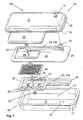
- Fig. 1
- in dreidimensionaler Explosionsansicht eine erfindungsgemäße Abgasanlage mit einem Katalysatorelement und einem gradlinigen Abgaskanal sowie einem Isolationselement,
- Fig. 2
- in dreidimensionaler Explosionsansicht eine ähnliche erfindungsgemäße Abgasanlage - wie in Fig. 1 - mit zusätzlichen Lüftungsdurchbrüchen in der Vorderschale und einem Injektor, und
- Fig. 3
- in dreidimensionaler Explosionsansicht eine weitere erfindungsgemäße Abgasanlage mit zwei Katalysatorelementen und einem mäanderförmigen Abgaskanal.
- Fig. 1
- in a three-dimensional exploded view of an exhaust system according to the invention with a catalyst element and a straight-line exhaust duct and an insulation element,
- Fig. 2
- in a three-dimensional exploded view of a similar exhaust system according to the invention - as in Fig. 1 - with additional ventilation openings in the front shell and an injector, and
- Fig. 3
- in a three-dimensional exploded view of another exhaust system according to the invention with two catalyst elements and a meandering exhaust duct.
In Figur 1 ist eine erste Variante der erfindungsgemäßen Abgasanlage 100 dargestellt. Dabei ist das Außengehäuse 10 der Abgasanlage 100 im Wesentlichen quaderförmig. Dieses besteht im vorliegenden Fall aus einer Vorderschale 11 und einer Hinterschale 12, wobei die Erfindung nicht auf ein zweiteiliges Gehäuse 10 begrenzt ist. In der Hinterschale 12 ist ein Abgaseinlass 16 für das eintretende Abgas aus dem Verbrennungsmotor vorgesehen. Da die Öffnungsfläche der Hinterschale 12 und der Vorderschale 11 durch die vorhandene Katalysatorkammer 20 geschlossen ist, entsteht in der Vorderschale 11 ein erster Bereich 18 und in der Hinterschale 12 ein zweiter Bereich 19, wobei die beiden Bereiche 18, 19 gasdicht voneinander getrennt sind. Somit muss das eingetretene Abgas aus dem zweiten Bereich 19 durch die fünf kreisförmigen Eintrittsöffnungen 24 in die Katalysatorkammer 20 eintreten. Die Eintrittsöffnungen 24 sind zu diesem Zweck in der zweiten Kammerhälfte 22 vorgesehen. Nachdem nun das Abgas in die Katalysatorkammer 20 gelangt ist, wird es durch ein Katalysatorelement 33 geführt. Die eigentliche Katalysatorkammer 20 ist quaderförmig ausgestaltet, damit das rechteckige Katalysatorelement 33 platzsparend angeordnet werden kann. Die quaderförmigen Aussparungen der Katalysatorkammer 20 sind durch einen Umformprozess in die beiden Kammerhälften 21 und 22 eingeformt worden. Nachdem das Abgas in dem Katalysatorelement 33 konvertiert wurde, kann es nunmehr in den Abgaskanal 23 gelangen. Dieser ist gradlinig in der ersten und zweiten Kammerhälfte 21, 22, wie die eigentliche Katalysatorkammer auch, eingearbeitet. Der Abgaskanal 23 erstreckt sich dabei über die gesamte Breite bzw. Länge des Katalysatorelementes 33. Somit beginnt eine katalysatorseitige Öffnung 27 des Abgaskanals 23 in etwa linksbündig mit dem Katalysatorelement 33.FIG. 1 shows a first variant of the
Um das Katalysatorelement 33 auf einfache Art und Weise in der Katalysatorkammer 20 ortsfest zu positionieren, sind zwei Distanzscheiben 36 vorgesehen, die zwischen der ersten Kammerhälfte 21 und dem Katalysatorelement 33 sowie zwischen dem Katalysatorelement 33 und der zweiten Kammerhälfte 22 vorgesehen sind. Die beiden Kammerhälften 21, 22 der Katalysatorkammer 20 werden durch das Verbindungselement 32, welches durch die beiden Distanzscheiben 36 geführt wird, fest- bzw. zusammengehalten. Das reversibel lösbare Verbindungselement 32 ist im vorliegenden Fall zweitteilig ausgestaltet und besteht beispielsweise aus einer Schraube und einer Mutter.In order to position the
Das konvertierte Abgas gelangt aus dem Abgaskanal 23 durch die Austrittsöffnung 25. Diese kann innerhalb des Außengehäuses 10 unterhalb der Vorderschale 11 enden. Ebenfalls ist es denkbar, dass die Austrittsöffnung 25 auch durch einen Abgasauslass 13 in der Vorderschale 11 durchgeführt wird, so dass das Abgas direkt ins Freie gelangt. Damit die Vorderschale 11 nicht unnötig erwärmt wird, isf ein zusätzliches Isolationselement 37 zwischen der Katalysatorkammer 20 bzw. der ersten Kammerhälfte 21 und der Vorderschale 11 vorgesehen. Dieses Isolationselement 37 kann beispielsweise aus einem Kissen aus Glasfasern bestehen.The converted exhaust gas passes from the
Die Figur 2 offenbart eine ähnliche Ausführungsform zur erfindungsgemäßen Abgasanlage 100 aus Figur 1. Dabei sind die Hinterschale 12 und die Katalysatorkammer 20 baugleich ausgestaltet. Nur die Austrittsöffnung 25 des Abgaskanals 23 und die Vorderschale 11 weisen bauliche Veränderungen im Vergleich zur Abgasanlage 100 aus Figur 1 auf. In der Figur 2 ist die Austrittsöffnung 25 offen aufgebaut, in dem ein Ringspalt vorgesehen ist, durch den Gase aus dem ersten Bereich 18 mit dem austretenden Abgasstrom mitgerissen werden. Zusätzlich wird beispielsweise ein Injektor 26 bzw. eine Düse 26, insbesondere Venturidüse beim Abgasauslass 13 verwendet, wodurch eine Kühlströmung im ersten Bereich 18 unter der Vorderschale 11 erzeugt wird. Hierzu sind in der Vorderschale 11 zusätzliche Lüftungsdurchbrüche 14 vorgesehen, durch die Frischluft in Abgasanlage 100 eindringen kann. Diese Frischluft wird durch den erzeugten Sog beim Austreten des Abgases unter die Vorderschale 11 gezogen. Durch diese Zwangskonvektion findet eine Kühlung der Vorderschale 11 statt. Gleichzeitig werden die heißen, konvertierten Abgase mit der angesaugten Frischluft beim Austreten aus dem Injektor 26 vermischt, wodurch ebenfalls eine Abkühlung des Abgases stattfindet. In der Ausführungsvariante der Abgasanlage 100 aus Figur 2 kann die kleinere Austrittsöffnung 25 bis in den Injektor 26 bzw. die Düse 26 ragen.FIG. 2 discloses a similar embodiment of the
Bei der Figur 3 ist zwar das Außengehäuse 10 baugleich zur Abgasanlage 100 aus der Figur 1 aufgebaut, allerdings wird eine andersartig ausgestaltete Katalysatorkammer 20 verwendet. Darüber hinaus kommen zwei Katalysatorelemente 33 und 34 zum Einsatz, die innerhalb der Katalysatorkammer 20 angeordnet sind. Um einen gewissen Mindestabstand zwischen den lochblechartigen Katalysatorelementen 33, 34 zu erzeugen, wird ein Distanzrahmen 35 eingesetzt. Dieser Distanzrahmen 35 besteht im Wesentlichen aus einem rechtwinkligen Blech, wobei in den Eckbereichen zusätzliche Distanzstücke vorgesehen sind, um den Abstand zwischen den Katalysatorelementen 33, 34 zu vergrößern. Der Distanzrahmen 35 ist mittig ausgestanzt, so dass das Abgas ohne Strömungswiderstand von dem ersten Katalysatorelement 33 zum zweiten Katalysatorelement 34 gelangen kann. Zusätzlich können Distanzscheiben 36 zwischen den Katalysatorelementen und den Kammerhälften 21, 22 eingesetzt werden. In der vorliegenden Ausführungsvariante sind insgesamt sechs großflächige Eintrittsöffnungen 24 in der ersten Kammerhälfte 21 vorgesehen, wodurch das bisher noch unkonvertierte Abgas in die Katalysatorkammer 20 eintritt. Damit die Katalysatorelemente 33, 34 nicht direkt an den Kammerhälften 21, 22 großflächig zum Anliegen kommen, sind zusätzliche Distanzstücke 31 in die Kammerhälften 21, 22 eingeformt. Diese Einformung kann zum Beispiel durch Stanzen oder Pressen bzw. Tiefziehen geschehen. Der an die Katalysatorkammer 20 anschließende Abgaskanal 23 ist mäanderförmig ausgestaltet. Dieser Abgaskanal 23 ist in die erste Kammerhälfte 21 und die zweite Kammerhälfte 22 eingeformt. Ausreichend könnte es auch sein, wenn der Abgaskanal 23 nur in eine Kammerhälfte 21 oder 22 eingeformt wäre.In the figure 3, although the
Um einerseits den ersten Bereich 18 vom zweiten Bereich 19 des Innenraumes der Abgasanlage 100 zu trennen, ist die erste Kammerhälfte 21 großflächig ausgestaltet, so dass hierdurch der komplette Querschnitt des Außengehäuses 10 verdeckt ist. Gleichzeitig dienen die Flächen links- und rechtsseitig vom Abgaskanal 23 als Kühlflächen 28, wodurch zusätzliche Wärme des Abgaskanals 23 abgeleitet werden kann. Um möglichst Material einzusparen, kann bei der zweiten Kammerhälfte 22 auf diese Kühlflächen 28 verzicht werden. Selbstverständlich können die Kühlflächen 28 auch nur an der zweiten Kammerhälfte 22 vorgesehen sein. Außerdem bleibt das Außengehäuse durch den allseitigen Abstand zum Kanal bzw. zur Kammer auf einem niedrigen Temperatumiveau.On the one hand to separate the
Um die beiden Kammerhälften 21, 22 gasdicht zu verschließen, werden die beiden Kammerhälften 21, 22 durch ein Verbindungselement 32 festgehalten. Durch die Einpunktfixierung neigt das Katalysatorelement nicht zum Beulen, wenn es sich durch Erwärmung ausdehnt. Dieses Verbindungselement 32 besteht wieder aus einer Schraube und einer Mutter. Allerdings kann auch eine Nietverbindung oder dergleichen eingesetzt werden. Darüber hinaus können die beiden Kammerhälften 21, 22 auch nur in ihren Randbereichen 29, 30 zusammengehalten werden. Dieses kann beispielsweise durch das Einklemmen der Kammerhälften zwischen der Vorderschale 11 und der Hinterschale 12 geschehen. Auch können die beiden Kammerhälften 21, 22 verschweißt oder verlötet werden.To close the two
Wie bereit beschrieben, ist der Abgaskanal 23 in der Figur 3 mäanderförmig ausgestaltet und gleicht der Ziffer "7". Dabei ist die katalysatorseitige Öffnung 27 nicht über die gesamte Breite der Katalysatorelemente 33, 34 angeordnet, sondern überlappt nur einen geringen Teil. Das konvertierte Abgas muss durch diese Öffnung 27 in den Abgaskanal 23 gelangen, um dann durch die verschiedenen Bögen bzw. Knicke 23c im Abgaskanal 23 geleitet zu werden. Durch diese Knicke und Bögen 23c lässt sich die Länge des Abgaskanals 23 verlängern. Hierdurch kann eine Flammenbildung außerhalb der Abgasanlage 100 vermieden werden.As already described, the
Abschließend ist zu erwähnen, dass die zuvor beschriebenen technischen Merkmale einzeln oder in Kombination bei der erfindungsgemäßen Abgasanlage 100 eingesetzt werden können, sofern sie sich nicht gegenseitig ausschließen. Die Abgasanlage 100 kann auch als Anfangs-, Mittel oder Endlage für eine teilweise bestehende Abgasanlage verwendet werden.Finally, it should be mentioned that the technical features described above can be used individually or in combination in the
- 100100
- Abgasanlageexhaust system
- 1010
- Außengehäuseouter casing
- 1111
- Vorderschalefront shell
- 1212
- Hinterschalebackshell
- 1313
- Abgasauslass in 11Exhaust outlet in 11
- 1414
- Lüftungsdurchbrüche in 11Ventilation breakthroughs in 11
- 1515
- Randbereich von 11Border area of 11
- 1616
- Abgaseinlass in 12Exhaust inlet in 12
- 1717
- Randbereich von 12Border area of 12
- 1818
- ersten Bereichfirst area
- 1919
- zweiter Bereichsecond area
- 2020
- Katalysatorkammercatalyst chamber
- 2121
- erste Kammerhälftefirst chamber half
- 2222
- zweite Kammerhälftesecond chamber half
- 2323
- Abgaskanalexhaust duct
- 23a23a
- unterer Teil des Abgaskanalslower part of the exhaust duct
- 23b23b
- oberer Teil des Abgaskanalsupper part of the exhaust duct
- 23c23c
- Bogen bzw. Knick im AbgaskanalBow or kink in the exhaust duct
- 2424
- Eintrittsöffnung von 20Entrance opening of 20
- 2525
- Austrittsöffnung von 23Outlet opening of 23
- 2626
- Injektor bzw. Düse, insbesondere VenturidüseInjector or nozzle, in particular Venturi nozzle
- 2727
- katalysatorseitige Öffnung von 23catalyst side opening of 23
- 2828
- Kühlflächecooling surface
- 2929
- Randbereich von 21Border area of 21
- 3030
- Randbereich von 22Border area of 22
- 3131
- Distanzstückspacer
- 3232
- Verbindungselement (z. B. Schraube und Mutter)Connecting element (eg screw and nut)
- 3333
- Katalysatorelement a)Catalyst element a)
- 3434
- Katalysatorelement b)Catalyst element b)
- 3535
- Distanzrahmen (mit Distanzstücken)Spacer frame (with spacers)
- 3636
- Distanzscheibespacer
- 3737
- Isolationselementinsulation element
Claims (18)
mit einer Katalysatorkammer (20), in der zumindest ein Katalysatorelement (33, 34) angeordnet ist, und
mit einem Abgaskanal (23), aus dem Abgas aus der Katalysatorkammer (20) geleitet wird, dadurch gekennzeichnet, dass die Katalysatorkammer (20) zusätzlich den Abgaskanal (23) bildet, wobei die Katalysatorkammer (20) wenigstens zwei Kammerhälften (21, 22) aufweist und der Abgaskanal (23) in zumindest einer Kammerhälfte (21, 22) materialeinheitlich und einteilig vorgesehen ist.Exhaust system (100) for an internal combustion engine with an outer housing (10) which contains at least one rear shell (12) and one front shell (11), and
with a catalyst chamber (20), in which at least one catalyst element (33, 34) is arranged, and
with an exhaust gas duct (23) from which exhaust gas is passed from the catalyst chamber (20), characterized in that the catalyst chamber (20) additionally forms the exhaust gas duct (23), the catalyst chamber (20) having at least two chamber halves (21, 22) and the exhaust passage (23) in at least one chamber half (21, 22) of the same material and is provided in one piece.
dass in einer anderen Kammerhälfte (21, 22), welche benachbart zur Vorderschale (11) angeordnet ist, wenigstens eine Austrittsöffnung (25), die im Bereich des Abgasauslasses (13) der Vorderschale (11) liegt, vorhanden ist, wodurch die Abgase aus der Katalysatorkammer (20) direkt oder indirekt ins Freie gelangen.Exhaust system according to one of the preceding claims, characterized in that in a chamber half (21, 22), which is arranged adjacent to the rear shell (12) with an exhaust gas inlet (16), at least one inlet opening (24) is provided, through which the exhaust gas in the catalyst chamber (20) passes, and
that in another chamber half (21, 22), which is arranged adjacent to the front shell (11), at least one outlet opening (25) in the region of the exhaust outlet (13) of the front shell (11) is present, whereby the exhaust gases from the catalyst chamber (20) get directly or indirectly into the open.
Applications Claiming Priority (1)
| Application Number | Priority Date | Filing Date | Title |
|---|---|---|---|
| DE202005013804U DE202005013804U1 (en) | 2005-08-31 | 2005-08-31 | catalyst chamber |
Publications (3)
| Publication Number | Publication Date |
|---|---|
| EP1760285A2 true EP1760285A2 (en) | 2007-03-07 |
| EP1760285A3 EP1760285A3 (en) | 2007-03-14 |
| EP1760285B1 EP1760285B1 (en) | 2010-05-12 |
Family
ID=37398678
Family Applications (1)
| Application Number | Title | Priority Date | Filing Date |
|---|---|---|---|
| EP06016100A Not-in-force EP1760285B1 (en) | 2005-08-31 | 2006-08-02 | Catalyst chamber |
Country Status (6)
| Country | Link |
|---|---|
| US (1) | US7617675B2 (en) |
| EP (1) | EP1760285B1 (en) |
| JP (1) | JP4928872B2 (en) |
| CN (2) | CN1924314A (en) |
| AT (1) | ATE467752T1 (en) |
| DE (2) | DE202005013804U1 (en) |
Families Citing this family (1)
| Publication number | Priority date | Publication date | Assignee | Title |
|---|---|---|---|---|
| IT1392528B1 (en) * | 2008-12-30 | 2012-03-09 | Emak Spa | DEVICE FOR EVACUATING GAS EXHAUST FROM AN INTERNAL COMBUSTION ENGINE FOR PORTABLE WORK TOOLS |
Citations (5)
| Publication number | Priority date | Publication date | Assignee | Title |
|---|---|---|---|---|
| DE3013691A1 (en) * | 1979-04-25 | 1980-11-06 | Gen Motors Corp | CATALYTIC CONVERTER FOR ENGINE EXHAUST GASES |
| US4265332A (en) * | 1979-06-21 | 1981-05-05 | Fmc Corporation | Heat extracting muffler system |
| US4741411A (en) * | 1987-01-14 | 1988-05-03 | Deere & Company | Muffler system |
| DE3829668A1 (en) * | 1987-12-08 | 1989-06-22 | Stihl Maschf Andreas | EXHAUST SILENCER FOR TWO-STROKE ENGINES |
| US5218817A (en) * | 1991-04-26 | 1993-06-15 | Honda Giken Kogyo Kabushiki Kaisha | Method and apparatus of purifying exhaust gas from internal combustion engine |
Family Cites Families (14)
| Publication number | Priority date | Publication date | Assignee | Title |
|---|---|---|---|---|
| JPS601685B2 (en) * | 1977-03-17 | 1985-01-17 | キヤノン株式会社 | magnetic recording method |
| US4235843A (en) * | 1978-08-14 | 1980-11-25 | Toyo Kogyo Co., Ltd. | Catalytic converter |
| FR2624202A1 (en) * | 1987-12-08 | 1989-06-09 | Stihl Andreas | QUIET FOR TWO-STROKE ENGINES |
| US4894987A (en) * | 1988-08-19 | 1990-01-23 | Ap Parts Manufacturing Company | Stamp formed muffler and catalytic converter assembly |
| US5736690A (en) * | 1994-07-18 | 1998-04-07 | Aktiebolaget Electrolux | Muffler with catalytic converter |
| SE9600204L (en) * | 1996-01-17 | 1997-05-12 | Electrolux Ab | Catalytic silencer for smaller combustion engine for eg portable work tools |
| JPH09228836A (en) * | 1996-02-23 | 1997-09-02 | Kubota Corp | Muffler cooling device |
| SE9703582L (en) | 1997-10-01 | 1999-04-02 | Electrolux Ab | Catalytic converter muffler |
| DE10042145A1 (en) * | 2000-08-26 | 2002-03-07 | Stihl Maschf Andreas | Exhaust silencer for an internal combustion engine |
| DE10139700B4 (en) * | 2000-10-11 | 2013-01-03 | Andreas Stihl Ag & Co. | Internal combustion engine as a drive motor in a portable, hand-held implement |
| DE10239132B4 (en) * | 2002-08-27 | 2012-11-15 | Andreas Stihl Ag & Co | exhaust silencer |
| JP4381868B2 (en) * | 2004-04-07 | 2009-12-09 | 本田技研工業株式会社 | Exhaust muffler with engine exhaust purification function |
| JP2005325756A (en) * | 2004-05-13 | 2005-11-24 | Orion Mach Co Ltd | Exhaust emission control device |
| JP3955293B2 (en) * | 2004-08-06 | 2007-08-08 | 株式会社共立 | Muffler with catalyst for internal combustion engine |
-
2005
- 2005-08-31 DE DE202005013804U patent/DE202005013804U1/en not_active Expired - Lifetime
-
2006
- 2006-08-02 EP EP06016100A patent/EP1760285B1/en not_active Not-in-force
- 2006-08-02 DE DE502006006925T patent/DE502006006925D1/en active Active
- 2006-08-02 AT AT06016100T patent/ATE467752T1/en active
- 2006-08-21 US US11/466,020 patent/US7617675B2/en not_active Expired - Fee Related
- 2006-08-30 CN CNA2006101151875A patent/CN1924314A/en active Pending
- 2006-08-30 CN CN201010126504A patent/CN101798945A/en active Pending
- 2006-08-30 JP JP2006233290A patent/JP4928872B2/en not_active Expired - Fee Related
Patent Citations (5)
| Publication number | Priority date | Publication date | Assignee | Title |
|---|---|---|---|---|
| DE3013691A1 (en) * | 1979-04-25 | 1980-11-06 | Gen Motors Corp | CATALYTIC CONVERTER FOR ENGINE EXHAUST GASES |
| US4265332A (en) * | 1979-06-21 | 1981-05-05 | Fmc Corporation | Heat extracting muffler system |
| US4741411A (en) * | 1987-01-14 | 1988-05-03 | Deere & Company | Muffler system |
| DE3829668A1 (en) * | 1987-12-08 | 1989-06-22 | Stihl Maschf Andreas | EXHAUST SILENCER FOR TWO-STROKE ENGINES |
| US5218817A (en) * | 1991-04-26 | 1993-06-15 | Honda Giken Kogyo Kabushiki Kaisha | Method and apparatus of purifying exhaust gas from internal combustion engine |
Also Published As
| Publication number | Publication date |
|---|---|
| CN101798945A (en) | 2010-08-11 |
| CN1924314A (en) | 2007-03-07 |
| US20080110160A1 (en) | 2008-05-15 |
| EP1760285A3 (en) | 2007-03-14 |
| JP4928872B2 (en) | 2012-05-09 |
| EP1760285B1 (en) | 2010-05-12 |
| DE202005013804U1 (en) | 2007-01-11 |
| JP2007064223A (en) | 2007-03-15 |
| DE502006006925D1 (en) | 2010-06-24 |
| ATE467752T1 (en) | 2010-05-15 |
| US7617675B2 (en) | 2009-11-17 |
Similar Documents
| Publication | Publication Date | Title |
|---|---|---|
| DE2643240C2 (en) | ||
| DE3335822A1 (en) | METHOD AND DEVICE FOR NOISE REDUCTION ON MUFFLERS | |
| DE19900310B4 (en) | Catalytic converter for a muffler of a small motor | |
| DE10060522B4 (en) | Exhaust silencer for a fuel-operated heater | |
| EP2027372A1 (en) | Off-line filter with improved filter efficiency | |
| AT396170B (en) | EXHAUST SYSTEM FOR TWO-STROKE COMBUSTION ENGINES | |
| DE4407088A1 (en) | External catalyst for small internal combustion engines | |
| DE3007866C2 (en) | ||
| EP0542124A1 (en) | Silencer | |
| DE60018201T2 (en) | DEVICE FOR THE SELECTIVE COOLING OF EXHAUST GASES OF A MOTOR VEHICLE ENGINE | |
| DE19755126A1 (en) | Catalytic converter arrangement for exhaust gas system of motor vehicle IC engine | |
| EP1760285B1 (en) | Catalyst chamber | |
| EP1559882B1 (en) | Exhaust purification device and process for manufacturing an exhaust purification device | |
| DE202005007861U1 (en) | Mäanderkatalysator | |
| DE10144015A1 (en) | Exhaust system for multi-cylinder internal combustion engines | |
| DE102019217853A1 (en) | EGR COOLER | |
| DE3015444A1 (en) | EXHAUST SILENCER | |
| EP1486649B1 (en) | Catalyst and process for its production | |
| DE102008060787A1 (en) | Self-supporting holder for catalyst carrier body | |
| EP1830044B1 (en) | Exhaust system | |
| DE102005044442B4 (en) | exhaust silencer | |
| DE10359073A1 (en) | Exhaust manifold for internal combustion engine, has feather seal arranged between gas conducting body and flange so that temperature conditional expansion takes place relative to flange, where body moves relative to flange with expansion | |
| DE10212050B4 (en) | silencer | |
| DE10259034A1 (en) | The exhaust purification device | |
| DE102021115392A1 (en) | Silencer for an exhaust system of an internal combustion engine |
Legal Events
| Date | Code | Title | Description |
|---|---|---|---|
| PUAI | Public reference made under article 153(3) epc to a published international application that has entered the european phase |
Free format text: ORIGINAL CODE: 0009012 |
|
| PUAL | Search report despatched |
Free format text: ORIGINAL CODE: 0009013 |
|
| AK | Designated contracting states |
Kind code of ref document: A2 Designated state(s): AT BE BG CH CY CZ DE DK EE ES FI FR GB GR HU IE IS IT LI LT LU LV MC NL PL PT RO SE SI SK TR |
|
| AX | Request for extension of the european patent |
Extension state: AL BA HR MK YU |
|
| AK | Designated contracting states |
Kind code of ref document: A3 Designated state(s): AT BE BG CH CY CZ DE DK EE ES FI FR GB GR HU IE IS IT LI LT LU LV MC NL PL PT RO SE SI SK TR |
|
| AX | Request for extension of the european patent |
Extension state: AL BA HR MK YU |
|
| 17P | Request for examination filed |
Effective date: 20070504 |
|
| 17Q | First examination report despatched |
Effective date: 20070620 |
|
| AKX | Designation fees paid |
Designated state(s): AT BE BG CH CY CZ DE DK EE ES FI FR GB GR HU IE IS IT LI LT LU LV MC NL PL PT RO SE SI SK TR |
|
| GRAP | Despatch of communication of intention to grant a patent |
Free format text: ORIGINAL CODE: EPIDOSNIGR1 |
|
| GRAS | Grant fee paid |
Free format text: ORIGINAL CODE: EPIDOSNIGR3 |
|
| GRAA | (expected) grant |
Free format text: ORIGINAL CODE: 0009210 |
|
| AK | Designated contracting states |
Kind code of ref document: B1 Designated state(s): AT BE BG CH CY CZ DE DK EE ES FI FR GB GR HU IE IS IT LI LT LU LV MC NL PL PT RO SE SI SK TR |
|
| REG | Reference to a national code |
Ref country code: GB Ref legal event code: FG4D Free format text: NOT ENGLISH |
|
| REG | Reference to a national code |
Ref country code: CH Ref legal event code: EP |
|
| REG | Reference to a national code |
Ref country code: IE Ref legal event code: FG4D Free format text: LANGUAGE OF EP DOCUMENT: GERMAN |
|
| REF | Corresponds to: |
Ref document number: 502006006925 Country of ref document: DE Date of ref document: 20100624 Kind code of ref document: P |
|
| REG | Reference to a national code |
Ref country code: NL Ref legal event code: VDEP Effective date: 20100512 |
|
| LTIE | Lt: invalidation of european patent or patent extension |
Effective date: 20100512 |
|
| PG25 | Lapsed in a contracting state [announced via postgrant information from national office to epo] |
Ref country code: LT Free format text: LAPSE BECAUSE OF FAILURE TO SUBMIT A TRANSLATION OF THE DESCRIPTION OR TO PAY THE FEE WITHIN THE PRESCRIBED TIME-LIMIT Effective date: 20100512 Ref country code: ES Free format text: LAPSE BECAUSE OF FAILURE TO SUBMIT A TRANSLATION OF THE DESCRIPTION OR TO PAY THE FEE WITHIN THE PRESCRIBED TIME-LIMIT Effective date: 20100823 Ref country code: SE Free format text: LAPSE BECAUSE OF FAILURE TO SUBMIT A TRANSLATION OF THE DESCRIPTION OR TO PAY THE FEE WITHIN THE PRESCRIBED TIME-LIMIT Effective date: 20100512 Ref country code: NL Free format text: LAPSE BECAUSE OF FAILURE TO SUBMIT A TRANSLATION OF THE DESCRIPTION OR TO PAY THE FEE WITHIN THE PRESCRIBED TIME-LIMIT Effective date: 20100512 |
|
| PG25 | Lapsed in a contracting state [announced via postgrant information from national office to epo] |
Ref country code: SI Free format text: LAPSE BECAUSE OF FAILURE TO SUBMIT A TRANSLATION OF THE DESCRIPTION OR TO PAY THE FEE WITHIN THE PRESCRIBED TIME-LIMIT Effective date: 20100512 Ref country code: FI Free format text: LAPSE BECAUSE OF FAILURE TO SUBMIT A TRANSLATION OF THE DESCRIPTION OR TO PAY THE FEE WITHIN THE PRESCRIBED TIME-LIMIT Effective date: 20100512 Ref country code: IS Free format text: LAPSE BECAUSE OF FAILURE TO SUBMIT A TRANSLATION OF THE DESCRIPTION OR TO PAY THE FEE WITHIN THE PRESCRIBED TIME-LIMIT Effective date: 20100912 Ref country code: LV Free format text: LAPSE BECAUSE OF FAILURE TO SUBMIT A TRANSLATION OF THE DESCRIPTION OR TO PAY THE FEE WITHIN THE PRESCRIBED TIME-LIMIT Effective date: 20100512 |
|
| REG | Reference to a national code |
Ref country code: IE Ref legal event code: FD4D |
|
| PG25 | Lapsed in a contracting state [announced via postgrant information from national office to epo] |
Ref country code: PL Free format text: LAPSE BECAUSE OF FAILURE TO SUBMIT A TRANSLATION OF THE DESCRIPTION OR TO PAY THE FEE WITHIN THE PRESCRIBED TIME-LIMIT Effective date: 20100512 Ref country code: GR Free format text: LAPSE BECAUSE OF FAILURE TO SUBMIT A TRANSLATION OF THE DESCRIPTION OR TO PAY THE FEE WITHIN THE PRESCRIBED TIME-LIMIT Effective date: 20100813 Ref country code: CY Free format text: LAPSE BECAUSE OF FAILURE TO SUBMIT A TRANSLATION OF THE DESCRIPTION OR TO PAY THE FEE WITHIN THE PRESCRIBED TIME-LIMIT Effective date: 20100512 |
|
| PG25 | Lapsed in a contracting state [announced via postgrant information from national office to epo] |
Ref country code: EE Free format text: LAPSE BECAUSE OF FAILURE TO SUBMIT A TRANSLATION OF THE DESCRIPTION OR TO PAY THE FEE WITHIN THE PRESCRIBED TIME-LIMIT Effective date: 20100512 Ref country code: PT Free format text: LAPSE BECAUSE OF FAILURE TO SUBMIT A TRANSLATION OF THE DESCRIPTION OR TO PAY THE FEE WITHIN THE PRESCRIBED TIME-LIMIT Effective date: 20100913 Ref country code: IE Free format text: LAPSE BECAUSE OF FAILURE TO SUBMIT A TRANSLATION OF THE DESCRIPTION OR TO PAY THE FEE WITHIN THE PRESCRIBED TIME-LIMIT Effective date: 20100512 Ref country code: DK Free format text: LAPSE BECAUSE OF FAILURE TO SUBMIT A TRANSLATION OF THE DESCRIPTION OR TO PAY THE FEE WITHIN THE PRESCRIBED TIME-LIMIT Effective date: 20100512 |
|
| BERE | Be: lapsed |
Owner name: DOLMAR G.M.B.H. Effective date: 20100831 |
|
| PG25 | Lapsed in a contracting state [announced via postgrant information from national office to epo] |
Ref country code: RO Free format text: LAPSE BECAUSE OF FAILURE TO SUBMIT A TRANSLATION OF THE DESCRIPTION OR TO PAY THE FEE WITHIN THE PRESCRIBED TIME-LIMIT Effective date: 20100512 Ref country code: SK Free format text: LAPSE BECAUSE OF FAILURE TO SUBMIT A TRANSLATION OF THE DESCRIPTION OR TO PAY THE FEE WITHIN THE PRESCRIBED TIME-LIMIT Effective date: 20100512 Ref country code: CZ Free format text: LAPSE BECAUSE OF FAILURE TO SUBMIT A TRANSLATION OF THE DESCRIPTION OR TO PAY THE FEE WITHIN THE PRESCRIBED TIME-LIMIT Effective date: 20100512 |
|
| PLBE | No opposition filed within time limit |
Free format text: ORIGINAL CODE: 0009261 |
|
| STAA | Information on the status of an ep patent application or granted ep patent |
Free format text: STATUS: NO OPPOSITION FILED WITHIN TIME LIMIT |
|
| PG25 | Lapsed in a contracting state [announced via postgrant information from national office to epo] |
Ref country code: IT Free format text: LAPSE BECAUSE OF FAILURE TO SUBMIT A TRANSLATION OF THE DESCRIPTION OR TO PAY THE FEE WITHIN THE PRESCRIBED TIME-LIMIT Effective date: 20100512 Ref country code: MC Free format text: LAPSE BECAUSE OF NON-PAYMENT OF DUE FEES Effective date: 20100831 |
|
| REG | Reference to a national code |
Ref country code: CH Ref legal event code: PL |
|
| 26N | No opposition filed |
Effective date: 20110215 |
|
| GBPC | Gb: european patent ceased through non-payment of renewal fee |
Effective date: 20100812 |
|
| PG25 | Lapsed in a contracting state [announced via postgrant information from national office to epo] |
Ref country code: CH Free format text: LAPSE BECAUSE OF NON-PAYMENT OF DUE FEES Effective date: 20100831 Ref country code: LI Free format text: LAPSE BECAUSE OF NON-PAYMENT OF DUE FEES Effective date: 20100831 |
|
| REG | Reference to a national code |
Ref country code: FR Ref legal event code: ST Effective date: 20110502 |
|
| REG | Reference to a national code |
Ref country code: DE Ref legal event code: R097 Ref document number: 502006006925 Country of ref document: DE Effective date: 20110214 |
|
| PG25 | Lapsed in a contracting state [announced via postgrant information from national office to epo] |
Ref country code: BE Free format text: LAPSE BECAUSE OF NON-PAYMENT OF DUE FEES Effective date: 20100831 Ref country code: FR Free format text: LAPSE BECAUSE OF NON-PAYMENT OF DUE FEES Effective date: 20100831 |
|
| PG25 | Lapsed in a contracting state [announced via postgrant information from national office to epo] |
Ref country code: GB Free format text: LAPSE BECAUSE OF NON-PAYMENT OF DUE FEES Effective date: 20100812 |
|
| PG25 | Lapsed in a contracting state [announced via postgrant information from national office to epo] |
Ref country code: HU Free format text: LAPSE BECAUSE OF FAILURE TO SUBMIT A TRANSLATION OF THE DESCRIPTION OR TO PAY THE FEE WITHIN THE PRESCRIBED TIME-LIMIT Effective date: 20101113 Ref country code: LU Free format text: LAPSE BECAUSE OF NON-PAYMENT OF DUE FEES Effective date: 20100802 Ref country code: BG Free format text: LAPSE BECAUSE OF FAILURE TO SUBMIT A TRANSLATION OF THE DESCRIPTION OR TO PAY THE FEE WITHIN THE PRESCRIBED TIME-LIMIT Effective date: 20100512 |
|
| PG25 | Lapsed in a contracting state [announced via postgrant information from national office to epo] |
Ref country code: TR Free format text: LAPSE BECAUSE OF FAILURE TO SUBMIT A TRANSLATION OF THE DESCRIPTION OR TO PAY THE FEE WITHIN THE PRESCRIBED TIME-LIMIT Effective date: 20100512 |
|
| REG | Reference to a national code |
Ref country code: AT Ref legal event code: MM01 Ref document number: 467752 Country of ref document: AT Kind code of ref document: T Effective date: 20110802 |
|
| PG25 | Lapsed in a contracting state [announced via postgrant information from national office to epo] |
Ref country code: AT Free format text: LAPSE BECAUSE OF NON-PAYMENT OF DUE FEES Effective date: 20110802 |
|
| PG25 | Lapsed in a contracting state [announced via postgrant information from national office to epo] |
Ref country code: BG Free format text: LAPSE BECAUSE OF FAILURE TO SUBMIT A TRANSLATION OF THE DESCRIPTION OR TO PAY THE FEE WITHIN THE PRESCRIBED TIME-LIMIT Effective date: 20100812 |
|
| PGFP | Annual fee paid to national office [announced via postgrant information from national office to epo] |
Ref country code: DE Payment date: 20170921 Year of fee payment: 12 |
|
| REG | Reference to a national code |
Ref country code: DE Ref legal event code: R119 Ref document number: 502006006925 Country of ref document: DE |
|
| PG25 | Lapsed in a contracting state [announced via postgrant information from national office to epo] |
Ref country code: DE Free format text: LAPSE BECAUSE OF NON-PAYMENT OF DUE FEES Effective date: 20190301 |