EP1760834A2 - Electrical terminal assembly - Google Patents
Electrical terminal assembly Download PDFInfo
- Publication number
- EP1760834A2 EP1760834A2 EP06016756A EP06016756A EP1760834A2 EP 1760834 A2 EP1760834 A2 EP 1760834A2 EP 06016756 A EP06016756 A EP 06016756A EP 06016756 A EP06016756 A EP 06016756A EP 1760834 A2 EP1760834 A2 EP 1760834A2
- Authority
- EP
- European Patent Office
- Prior art keywords
- contact
- electrical connection
- side cable
- arrangement according
- connection arrangement
- Prior art date
- Legal status (The legal status is an assumption and is not a legal conclusion. Google has not performed a legal analysis and makes no representation as to the accuracy of the status listed.)
- Granted
Links
- 239000012777 electrically insulating material Substances 0.000 claims description 2
- 241000196324 Embryophyta Species 0.000 description 5
- 238000000034 method Methods 0.000 description 4
- 238000003780 insertion Methods 0.000 description 3
- 230000037431 insertion Effects 0.000 description 3
- 238000004804 winding Methods 0.000 description 3
- 239000004020 conductor Substances 0.000 description 2
- 238000010276 construction Methods 0.000 description 2
- 230000006378 damage Effects 0.000 description 2
- 238000009413 insulation Methods 0.000 description 2
- 241000233805 Phoenix Species 0.000 description 1
- 208000027418 Wounds and injury Diseases 0.000 description 1
- 239000003990 capacitor Substances 0.000 description 1
- 238000006073 displacement reaction Methods 0.000 description 1
- 208000014674 injury Diseases 0.000 description 1
- 238000009434 installation Methods 0.000 description 1
- 239000000463 material Substances 0.000 description 1
- 238000003825 pressing Methods 0.000 description 1
Images

Classifications
-
- H—ELECTRICITY
- H01—ELECTRIC ELEMENTS
- H01R—ELECTRICALLY-CONDUCTIVE CONNECTIONS; STRUCTURAL ASSOCIATIONS OF A PLURALITY OF MUTUALLY-INSULATED ELECTRICAL CONNECTING ELEMENTS; COUPLING DEVICES; CURRENT COLLECTORS
- H01R4/00—Electrically-conductive connections between two or more conductive members in direct contact, i.e. touching one another; Means for effecting or maintaining such contact; Electrically-conductive connections having two or more spaced connecting locations for conductors and using contact members penetrating insulation
- H01R4/24—Connections using contact members penetrating or cutting insulation or cable strands
- H01R4/2416—Connections using contact members penetrating or cutting insulation or cable strands the contact members having insulation-cutting edges, e.g. of tuning fork type
- H01R4/242—Connections using contact members penetrating or cutting insulation or cable strands the contact members having insulation-cutting edges, e.g. of tuning fork type the contact members being plates having a single slot
- H01R4/2425—Flat plates, e.g. multi-layered flat plates
- H01R4/2429—Flat plates, e.g. multi-layered flat plates mounted in an insulating base
- H01R4/2433—Flat plates, e.g. multi-layered flat plates mounted in an insulating base one part of the base being movable to push the cable into the slot
-
- H—ELECTRICITY
- H01—ELECTRIC ELEMENTS
- H01R—ELECTRICALLY-CONDUCTIVE CONNECTIONS; STRUCTURAL ASSOCIATIONS OF A PLURALITY OF MUTUALLY-INSULATED ELECTRICAL CONNECTING ELEMENTS; COUPLING DEVICES; CURRENT COLLECTORS
- H01R4/00—Electrically-conductive connections between two or more conductive members in direct contact, i.e. touching one another; Means for effecting or maintaining such contact; Electrically-conductive connections having two or more spaced connecting locations for conductors and using contact members penetrating insulation
- H01R4/28—Clamped connections, spring connections
- H01R4/48—Clamped connections, spring connections utilising a spring, clip, or other resilient member
- H01R4/4809—Clamped connections, spring connections utilising a spring, clip, or other resilient member using a leaf spring to bias the conductor toward the busbar
- H01R4/4828—Spring-activating arrangements mounted on or integrally formed with the spring housing
- H01R4/48365—Spring-activating arrangements mounted on or integrally formed with the spring housing with integral release means
-
- H—ELECTRICITY
- H01—ELECTRIC ELEMENTS
- H01R—ELECTRICALLY-CONDUCTIVE CONNECTIONS; STRUCTURAL ASSOCIATIONS OF A PLURALITY OF MUTUALLY-INSULATED ELECTRICAL CONNECTING ELEMENTS; COUPLING DEVICES; CURRENT COLLECTORS
- H01R2201/00—Connectors or connections adapted for particular applications
- H01R2201/22—Connectors or connections adapted for particular applications for transformers or coils
Definitions
- the invention relates to an electrical connection arrangement for the electrical connection of an electrical device, in particular an electric motor, with a lower part for receiving at least one device-side cable, with an upper part for receiving at least one connection-side cable and with a contact body for electrical connection of the device-side cable to the connection side Cable, wherein the lower part and the upper part consist essentially of electrically insulating material.
- Terminal blocks for example, are known from plant construction and are usually provided in a control cabinet for top hat rail mounting and consist of a lower part and an upper part ( Phoenix Contact Product Catalog "COMBICON - PCB Connection", 2000/01, pages 198-212 ).
- a device-side cable which has been freed from its end insulation, inserted into the lower part and there electrically connected to a arranged in the lower part of the contact body by a clamping or screw connection.
- Connection-side, stripped cable are then attached to or in a contact body, which is arranged in the upper part designed as a plug strip.
- connection arrangement which, however, is tailored to the specific use for connecting a connection cable to the stator winding ends of an external rotor motor.
- the lower part of this connection arrangement is provided for mounting on the motor housing, wherein the device-side cable - so the motor-side coil ends - are electrically connected to arranged in the lower part Kunststoffkörpem, which formed as cutting contacts are; the necessity of a preliminary stripping of the device-side cable ends does not exist.
- the distributed contact bodies each extend as far as a plug receptacle formed in the lower part into which the upper part designed as a plug strip can be inserted.
- Corresponding contact bodies which are in turn electrically connectable to the connection-side cables are arranged in the upper part.
- About jumpers that can be inserted into the upper part, arranged in the upper part contact body can be electrically connected to each other, which is used in particular to the desired interconnection of the motor windings to a star or triangular arrangement.
- the invention is therefore based on the object to provide an electrical connection arrangement with improved and simplified connection properties available.
- the electrical connection arrangement according to the invention in which this object is achieved, is initially and essentially characterized in that in the lower part at least one fastening means for fixing at least one device-side cable is formed, that the contact body is arranged in the upper part, that the contact body a first Having contact means and a second contact means, and that the contact body in the joining position of the lower part with the upper part with the first contact means contacted the device-side cable and the connection side cable is contactable with the second contact means.
- the electrical connection arrangement according to the invention is advantageous in several respects.
- the fact that the contact body is arranged in the upper part of the terminal assembly eliminates a contact point with respect to the known from the prior art terminal arrangements, namely the contact point between the arranged in the lower part and the upper part in the contact body.
- the contacting process of the device-side cable is much easier and safer, since the contact between the contact body and device-side cable is made only in the joining position of the lower part and the upper part. There is thus neither the risk of mechanical damage to the first contact means producing the connection nor the risk of an electric shock by touching the possibly under tension first contact means.
- connection arrangement according to the invention can be further improved in terms of their usability by the first contact means of the contact body is formed as a cutting contact. This has the advantage that the device-side cable can be processed completely isolated and after contacting by the cutting contacts a safe and vibration-proof electrical connection is made.
- the second contact means for contacting the connection-side cable is designed as a spring clamp or as a screw terminal.
- the contact body is further formed so that it can receive a leg of a jumper contacting, so that at least two contact bodies are electrically connected to each other.
- the usability of the terminal arrangement according to the invention for connecting an electric motor is ensured in order to enable the previously mentioned interconnection of different windings of electric polyphase motors.
- the fastening means is formed in the lower part in the form of a clamp which allows the clamping of a device-side cable without the aid of tools. This simplifies the connection process in hard to reach places, especially where you can not work both ways, for example, a hand must be used to secure the position.
- each upper part segment has at least one contact body and is separately connectable to the lower part.
- the individual shells can then be connected together as a terminal block.
- the upper part with the lower part or each upper segment with the lower part in the joining position can be locked, in particular by the upper part or the upper part segment associated latching elements engageable in the joining position with corresponding RastelementausEnglishept in the lower part of the terminal arrangement are.
- the locking element and the Rastelementausappelung are configured so that they act as a guide during assembly of the lower part and the upper part or the lower part and the upper part segment as well as an exact positioning of the first contact means relative to the fixing means of the lower part fixed device-side cable and thus ensuring a secure contact.
- the electrical arrangement according to the invention will be described with reference to several preferred embodiments for connecting an electric motor.
- the invention could just as well be based on other uses be described for connecting other electrical equipment; the electrical connection arrangement according to the invention is completely independent of the specific application and the function of the electrical device which is contacted with the electrical connection arrangement.
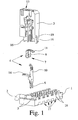
- Fig. 1 shows an exploded view of a preferred embodiment, the essential components of the terminal assembly according to the invention, comprising a lower part 1, which serves to receive a device-side cable 2, an upper part 3 for receiving a - not shown here - connection side cable and a contact body 4, by an electrical connection between the device-side cable 2 and the connection-side cable is made.
- fastening means 5 are further formed, with which the device-side cable 2 can be fixed to or in the lower part 1. The attachment of the device-side cable 2 in the lower part 1 by means of the fastening means 5 takes place without electrical contact of the device-side cable. 2
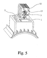
- the contact body 4 is assigned to the upper part 3 and fixed functionally in the upper part 3 in its installation position, which is shown in FIGS. 3, 5, 7 and 9.
- the contact body 4 is arranged in the upper part 3, that the contact body 4 contacted with a first contact means 6 attached in the lower part 1 device side cable 2 in the joining position of the lower part 1 with the upper part 3.
- the joining position of the lower part 1 and the upper part 3 is again shown in FIGS. 3, 5, 7 and 9.
- the contact body 4 has a second contact means 7, 8, via which the connection-side cable to the contact body 4 is electrically connectable and mechanically sufficiently fastened to the contact body 4, so that the electrical connection is ensured even under certain Auszug theory on the connection side cable.
- the first contact means 6 is designed as a cutting contact.
- the particular advantage of using a trained as a cutting contact first contact means 6 is just in connection with the terminal arrangement according to the invention is that the device-side cable 2 must not be exposed for contacting, so that the handling of the device-side cable 2 in its attachment to the Lower part 1 of the connection arrangement with the fastening means 5 is safely possible.
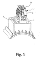
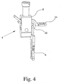
- the second contact means 7, 8 of the contact body 4 can in principle be configured in any desired manner. Illustrated are in FIGS. 1 and 5 to 10 each embodiment using spring clamps 7 and in Figs. 3 and 4 an embodiment using a screw 8 as a second contact means.
- the electrical connection arrangement according to the invention is not limited to these variants, but other connection techniques can be used.
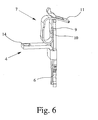
- the spring terminals 7 are configured in a known manner as a loop-shaped tension springs, with a plant leg 9 for contact with a busbar 10 and with a spring leg 11, the free end is angled in the direction of plant leg 9, wherein the free end of the abutment leg 9 passes through an opening in the spring leg 11 movable.
- Figures 1, 5, 6, 9 and 10 show embodiments in which the spring leg 11 of the spring-loaded terminals 7 faces the insertion direction of the connection-side cable.
- the spring terminal is shown in each case in its deflected, open position, which can be caused by external force, for example by pressing the spring terminal 7 with an operating tool. The operating tool is thereby brought in the usual way via an actuating opening in the upper part 3 of the terminal assembly to the spring terminal 7.
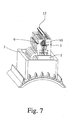
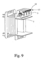
- the loop-shaped bent spring terminal 7 is arranged with its spring leg 11 facing away from the insertion direction of the connection-side cable in the upper part 3 of the connection arrangement.
- the operating principle is comparable to that of the previously described spring-loaded terminals 7, but the design of the spring-loaded terminal 7 according to FIGS. 7 and 8 permits a more compact design of the upper part 3 than is possible in the previously described embodiments.
- the spring clamp is designed as a U-shaped pawl spring in which the festzuklemmende conductor is pressed by the free end of a spring leg against a busbar and locks the conductor in the extension direction.
- the contact body 4 is not stretched substantially rectilinear as in the other illustrated embodiments, but the plant leg 9 of the spring terminal 7 and the busbar 10 are arranged opposite to the first contact means 6 substantially at right angles angled an overall flatter construction - measured from the bottom 1 of the terminal assembly is achieved.
- the contact body 4 is always formed so that it can receive a leg of a jumper 12.
- the contact body 4 in the embodiments of FIGS. 1 6 and 10 are each formed so that a contact leg 14 is formed on it, which serves an opening for receiving a preferably elastically or conically shaped leg of a jumper 12.
- the contact leg 14 is not formed on the contact body 4, but inserted into the screw 8 of the contact body 4, wherein a secure contact between the screw 8, the busbar 10 and the contact leg 14 by tightening the Screw terminal 8 is produced.
- a recess 13 is formed in the upper part 3 of the terminal assembly for receiving the jumper 12 is. On the one hand, this reduces or eliminates the risk of unwanted electrical contact with the conductive parts of the jumper 12 and, on the other hand, minimizes the risk of accidental removal of the jumper 12 from the upper part 3 of the terminal arrangement.
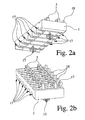
- Figures 2a and 2b illustrate the lower part 1 of the terminal assembly separately.
- the fixing of the device-side cable 2 serving fastening means 5 in the lower part 1 is here each formed as a pair of brackets.
- the fastening means 5 is formed in the lower part 1 and insofar consists of the same isolierrichen material as the entire lower part 1.
- a particularly good attachment of the device-side cable 2 by the fastener 5 is achieved when the lower part 1 in the region of Cable receptacle is formed trough-like, so that the device-side cable 2 not only flat on the lower part 1 rests, but at least partially surrounded by the lower part 1.
- the fastening means 5 designed as a clamp are so elastic that the device-side cable 2 to be fixed by them can be pressed into the fastening means 5 without tools.
- All illustrated embodiments of the terminal arrangement according to the invention show a modular shell 3, which consists of several shell segments, which are like a disk next to each other.
- each upper part segment has a contact body 4.
- the individual upper part segments can be fastened together, for example by a fixing rod, not shown, which is guided by corresponding holes in the upper part segments of the upper part.
- the fixation is produced by corresponding wedges and grooves or by corresponding latching pins and latching recesses which are provided on the sides of each upper part segment and can be connected to one another via the adjacent upper part segments to form a block.
- the lower part 1 of the connection arrangement furthermore has further fastening means 15 with the aid of which the lower part 1 is attached to a Mounting surface is fastened.
- the further fastening means 15 is configured as a latching bolt, which can be inserted into a mounting wall in a fixed manner.
- the further fastening means 15 in at least one screw receptacle - through hole - or a DIN rail receptacle for securing the electrical connection assembly to a DIN rail.
- the illustrated and described embodiments of the electrical connection arrangement all have the advantage of a particularly simple and safe electrical connection of electrical equipment, due to the arrangement of the contact body 4 in the upper part 3 of the terminal assembly and the achievable thereby contacting the contact body 4 with the device-side cable. 2 when assembling the lower part 1 and the upper part. 3
- connection arrangement according to FIG. 1 is furthermore designed so that the lower part 1 and the upper part 3 have corresponding guide means 18, 19 which force a selective joining movement of the upper part 3 relative to the lower part 1 during assembly, so that a secure contacting of the in the Lower part 1 fixed device-side cable 2 is ensured by designed as a cutting contact contact means 6 of the contact body 4.
- the guide means 18, 19 may also be formed as a guide pin and guide pin receptacle.
- the latching connection 16, 17 at the same time assume the function of the guide means 18, 19.
- the lower part 1 of the terminal arrangement is designed in the illustrated embodiments so that it can accommodate a total of six upper segments, whereby in particular the connection of three-phase motors is advantageously possible.
Abstract
Description
Die Erfindung betrifft eine elektrische Anschlußanordnung zum elektrischen Anschluß eines elektrischen Geräts, insbesondere eines elektrischen Motors, mit einem Unterteil zur Aufnahme wenigstens eines geräteseitigen Kabels, mit einem Oberteil zur Aufnahme wenigstens eines anschlußseitigen Kabels und mit einem Kontaktkörper zur elektrischen Verbindung des geräteseitigen Kabels mit dem anschlußseitigen Kabel, wobei das Unterteil und das Oberteil im wesentlichen aus elektrisch isolierendem Material bestehen.The invention relates to an electrical connection arrangement for the electrical connection of an electrical device, in particular an electric motor, with a lower part for receiving at least one device-side cable, with an upper part for receiving at least one connection-side cable and with a contact body for electrical connection of the device-side cable to the connection side Cable, wherein the lower part and the upper part consist essentially of electrically insulating material.
Elektrische Anschlußanordnungen der in Rede stehenden Art sind bekannt und werden zu ganz unterschiedlichen Kontaktierungs- und Anschlußzwecken eingesetzt. Aus dem Anlagenbau sind beispielsweise Reihenklemmen bekannt, die üblicherweise in einem Schaltschrank zur Hutschienen-Montage vorgesehen sind und aus einem Unterteil und einem Oberteil bestehen (
Aus der
Auch wenn der elektrische Anschluß eines Geräts mit der vorstehend beschriebenen Anschlußanordnung gegenüber dem erstgenannten Beispiel aus dem Stand der Technik aufgrund des Einsatzes von Schneidkontakten vereinfacht worden ist, ist der Anschlußvorgang trotzdem noch vergleichsweise aufwendig. Insbesondere beim Kontaktieren der geräteseitigen Kabel mit den Schneidkontakten besteht die Gefahr der mechanischen und elektrischen Verletzung, da nach Kontaktierung des geräteseitigen Kabels ein geräteseitig vorhandenes Potential - beispielsweise von einem Pufferkondensator - an den Schneidklemmen anliegt.Although the electrical connection of a device has been simplified with the above-described terminal arrangement compared to the first-mentioned example of the prior art due to the use of cutting contacts, the connection process is still relatively expensive. In particular, when contacting the device-side cable with the cutting contacts there is a risk of mechanical and electrical injury, since after contacting the device-side cable a device-side potential present - for example, from a buffer capacitor - is applied to the insulation displacement terminals.
Der Erfindung liegt daher die Aufgabe zugrunde, eine elektrische Anschlußanordnung mit verbesserten und vereinfachten Anschlußeigenschaften zur Verfügung zu stellen.The invention is therefore based on the object to provide an electrical connection arrangement with improved and simplified connection properties available.
Die erfindungsgemäße elektrische Anschlußanordnung, bei der diese Aufgabe gelöst ist, ist zunächst und im wesentlichen dadurch gekennzeichnet, daß in dem Unterteil wenigstens ein Befestigungsmittel zur Befestigung wenigstens eines geräteseitigen Kabels ausgebildet ist, daß der Kontaktkörper in dem Oberteil angeordnet ist, daß der Kontaktkörper ein erstes Kontaktmittel und ein zweites Kontaktmittel aufweist, und daß der Kontaktkörper in der Fügeposition des Unterteils mit dem Oberteil mit dem ersten Kontaktmittel das geräteseitige Kabel kontaktiert und mit dem zweiten Kontaktmittel das anschlußseitige Kabel kontaktierbar ist.The electrical connection arrangement according to the invention, in which this object is achieved, is initially and essentially characterized in that in the lower part at least one fastening means for fixing at least one device-side cable is formed, that the contact body is arranged in the upper part, that the contact body a first Having contact means and a second contact means, and that the contact body in the joining position of the lower part with the upper part with the first contact means contacted the device-side cable and the connection side cable is contactable with the second contact means.
Die erfindungsgemäße elektrische Anschlußanordnung ist in mehrfacher Hinsicht vorteilhaft. Dadurch, daß der Kontaktkörper im Oberteil der Anschlußanordnung angeordnet ist, entfällt eine Kontaktstelle gegenüber den aus dem Stand der Technik bekannten Anschlußanordnungen, nämlich die Kontaktstelle zwischen dem im Unterteil und dem im Oberteil angeordneten Kontaktkörper. Ferner wird der Kontaktierungsvorgang des geräteseitigen Kabels erheblich einfacher und sicherer, da der Kontakt zwischen Kontaktkörper und geräteseitigem Kabel erst in der Fügeposition des Unterteils und des Oberteils hergestellt wird. Damit besteht weder die Gefahr einer mechanischen Verletzung an dem die Verbindung herstellenden ersten Kontaktmittel noch die Gefahr eines elektrischen Schlages durch Berühren des möglicherweise unter Spannung stehenden ersten Kontaktmittels.The electrical connection arrangement according to the invention is advantageous in several respects. The fact that the contact body is arranged in the upper part of the terminal assembly, eliminates a contact point with respect to the known from the prior art terminal arrangements, namely the contact point between the arranged in the lower part and the upper part in the contact body. Furthermore, the contacting process of the device-side cable is much easier and safer, since the contact between the contact body and device-side cable is made only in the joining position of the lower part and the upper part. There is thus neither the risk of mechanical damage to the first contact means producing the connection nor the risk of an electric shock by touching the possibly under tension first contact means.
Die erfindungsgemäße Anschlußanordnung läßt sich hinsichtlich ihrer Verwendbarkeit noch weiter verbessern, indem das erste Kontaktmittel des Kontaktkörpers als Schneidkontakt ausgebildet wird. Dies hat den Vorteil, daß die geräteseitigen Kabel vollständig isoliert verarbeitet werden können und nach Kontaktierung durch die Schneidkontakte eine sichere und rüttelfeste elektrische Verbindung hergestellt ist.The connection arrangement according to the invention can be further improved in terms of their usability by the first contact means of the contact body is formed as a cutting contact. This has the advantage that the device-side cable can be processed completely isolated and after contacting by the cutting contacts a safe and vibration-proof electrical connection is made.
Nach weiteren vorteilhaften Ausgestaltungen der Erfindung ist das zweite Kontaktmittel zur Kontaktierung des anschlußseitigen Kabels als Federklemme oder als Schraubklemme ausgeführt. Hierdurch ist die elektrischen und mechanischen Verbindung des anschlußseitigen Kabels mit dem Kontaktkörper nahezu beliebig oft und leicht wieder lösbaren, wobei dennoch eine sichere elektrische Verbindung gewährleistet ist.According to further advantageous embodiments of the invention, the second contact means for contacting the connection-side cable is designed as a spring clamp or as a screw terminal. As a result, the electrical and mechanical connection of the connection-side cable with the contact body is almost as often and easily detachable again, yet a secure electrical connection is ensured.
Vorzugsweise ist der Kontaktkörper ferner so ausgebildet, daß er einen Schenkel einer Steckbrücke kontaktierend aufnehmen kann, so daß wenigstens zwei Kontaktkörper elektrisch miteinander verbindbar sind. Dadurch wird insbesondere auch die Verwendbarkeit der erfindungsgemäßen Anschlußanordnung zum Anschluß eines elektrischen Motors sichergestellt, um die schon zuvor genannte Verschaltung verschiedener Wicklungen elektrischer Mehrphasenmotoren zu ermöglichen.Preferably, the contact body is further formed so that it can receive a leg of a jumper contacting, so that at least two contact bodies are electrically connected to each other. As a result, in particular the usability of the terminal arrangement according to the invention for connecting an electric motor is ensured in order to enable the previously mentioned interconnection of different windings of electric polyphase motors.
Besonders vorteilhaft ist in diesem Zusammenhang, wenn zur Aufnahme einer Steckbrücke in dem Unterteil oder dem Oberteil der Anschlußanordnung eine Ausnehmung ausgebildet ist, insbesondere derart, daß eine Berührung elektrisch leitender Teile der Steckbrücke oder eine mechanische Beeinflussung der Steckbrücke in ihrer Montageposition nicht ohne weiteres möglich ist.It is particularly advantageous in this context, if a recess is formed for receiving a jumper in the lower part or the upper part of the terminal assembly, in particular such that a contact electrically conductive parts of the jumper or a mechanical influence of the jumper in its mounting position is not readily possible ,
Bei einer weiteren Ausgestaltung der erfindungsgemäßen Anschlußanordnung hat es sich als vorteilhaft erwiesen, wenn das Befestigungsmittel in dem Unterteil in Form einer Klammer ausgebildet ist, die das Einklemmen eines geräteseitigen Kabels ohne Zuhilfenahme von Werkzeug ermöglicht. Dies vereinfacht den Anschlußvorgang an schwer zugänglichen Stellen, vor allem dort, wo nicht beidhändig gearbeitet werden kann, beispielsweise eine Hand zur Lagesicherung verwendet werden muß.In a further embodiment of the terminal arrangement according to the invention, it has proved to be advantageous if the fastening means is formed in the lower part in the form of a clamp which allows the clamping of a device-side cable without the aid of tools. This simplifies the connection process in hard to reach places, especially where you can not work both ways, for example, a hand must be used to secure the position.
Bei einer weiteren vorteilhaften Ausgestaltung der Erfindung besteht das Oberteil aus mehreren Oberteilsegmenten, wobei jedes Oberteilsegment wenigstens einen Kontaktkörper aufweist und separat mit dem Unterteil verbindbar ist. Die einzelnen Oberteile können dann als Anschlußblock miteinander verbunden werden.In a further advantageous embodiment of the invention, the upper part of a plurality of upper part segments, wherein each upper part segment has at least one contact body and is separately connectable to the lower part. The individual shells can then be connected together as a terminal block.
In einer weiteren vorteilhaften Ausgestaltung der elektrischen Anschlußanordnung ist das Oberteil mit dem Unterteil bzw. jedes Oberteilsegment mit dem Unterteil in der Fügeposition verriegelbar, insbesondere durch dem Oberteil bzw. dem Oberteilsegment zugeordnete Rastelemente, die in Fügeposition mit korrespondierenden Rastelementausnehmungen im Unterteil der Anschlußanordnung in Eingriff bringbar sind. Besonders bevorzugt sind das Rastelement und die Rastelementausnehmung so ausgestaltet, daß sie beim Zusammenfügen des Unterteils und des Oberteils bzw. des Unterteils und des Oberteilsegments gleichsam wie eine Führung wirken und so eine exakte Positionierung des ersten Kontaktmittels gegenüber dem im Befestigungsmittel des Unterteils fixierten geräteseitigen Kabels und damit eine sichere Kontaktierung gewährleisten.In a further advantageous embodiment of the electrical connection arrangement, the upper part with the lower part or each upper segment with the lower part in the joining position can be locked, in particular by the upper part or the upper part segment associated latching elements engageable in the joining position with corresponding Rastelementausnehmungen in the lower part of the terminal arrangement are. Particularly preferably, the locking element and the Rastelementausnehmung are configured so that they act as a guide during assembly of the lower part and the upper part or the lower part and the upper part segment as well as an exact positioning of the first contact means relative to the fixing means of the lower part fixed device-side cable and thus ensuring a secure contact.
Im einzelnen gibt es nun eine Vielzahl von Möglichkeiten, die erfindungsgemäße elektrische Anschlußanordnung auszugestalten und weiterzubilden. Dazu wird verwiesen einerseits auf die dem Patentanspruch 1 nachgeordneten Patentansprüche, andererseits auf die folgende Beschreibung mehrerer Ausftihrungsbeispiele in Verbindung mit der Zeichnung. In der Zeichnung zeigt
- Fig. 1
- ein bevorzugtes Ausführungsbeispiel einer erfindungsgemäßen Anschlußanordnung in Explosionsdarstellung,
- Fig. 2a, 2b
- Ansichten des Unterteils eines Ausführungsbeispiels der erfindungsgemäßen Anschlußanordnung,
- Fig. 3
- ein weiteres Ausführungsbeispiel der erfindungsgemäßen Anschlußanordnung im Montagezustand,
- Fig. 4
- eine Detaildarstellung eines Kontaktkörpers, wie verwendet im Ausführungsbeispiel gemäß Fig. 3,
- Fig. 5
- ein drittes Ausführungsbeispiel der erfindungsgemäßen Anschlußanordnung im Montagezustand,
- Fig. 6
- eine Detaildarstellung eines Kontaktkörpers, wie verwendet im Ausführungsbeispiel gemäß Fig. 5,
- Fig. 7
- ein viertes Ausführungsbeispiel der erfindungsgemäßen. Anschlußanordnung im Montagezustand,
- Fig. 8
- eine Detaildarstellung eines Kontaktkörpers, wie verwendet im Ausführungsbeispiel gemäß Fig. 7,
- Fig. 9
- ein weiteres Ausführungsbeispiel der Anschlußanordnung im Montagezustand und
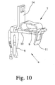
- Fig. 10
- eine Detaildarstellung eines Kontaktkörpers, einer Anschlußanordnung gemäß Fig. 9.
- Fig. 1
- A preferred embodiment of a terminal arrangement according to the invention in an exploded view,
- Fig. 2a, 2b
- Views of the lower part of an embodiment of the connection arrangement according to the invention,
- Fig. 3
- a further embodiment of the connection arrangement according to the invention in the assembled state,
- Fig. 4
- a detailed representation of a contact body, as used in the embodiment of FIG. 3,
- Fig. 5
- A third embodiment of the terminal assembly according to the invention in the assembled state,
- Fig. 6
- a detailed view of a contact body, as used in the embodiment of FIG. 5,
- Fig. 7
- A fourth embodiment of the invention. Connection arrangement in the assembled state,
- Fig. 8
- a detailed representation of a contact body, as used in the embodiment of FIG. 7,
- Fig. 9
- a further embodiment of the terminal assembly in the assembled state and
- Fig. 10
- a detailed view of a contact body, a terminal assembly of FIG. 9.
Im folgenden wird die erfindungsgemäße elektrische Anordnung anhand mehrerer bevorzugter Ausführungsbeispiele zum Anschluß eines Elektromotors beschrieben. Genausogut könnte die Erfindung auch anhand anderer Verwendungen zum Anschluß anderer elektrischer Geräte beschrieben werden; die erfindungsgemäße elektrische Anschlußanordnung ist vollkommen unabhängig von dem speziellen Anwendungsfall und der Funktion des elektrischen Geräts, das mit der elektrischen Anschlußanordnung kontaktiert wird.In the following, the electrical arrangement according to the invention will be described with reference to several preferred embodiments for connecting an electric motor. The invention could just as well be based on other uses be described for connecting other electrical equipment; the electrical connection arrangement according to the invention is completely independent of the specific application and the function of the electrical device which is contacted with the electrical connection arrangement.
Fig. 1 zeigt in Explosionsdarstellung anhand eines bevorzugten Ausführungsbeispiels die wesentlichen Bestandteile der erfindungsgemäßen Anschlußanordnung, aufweisend ein Unterteil 1, das der Aufnahme eines geräteseitigen Kabels 2 dient, ein Oberteil 3 zur Aufnahme eines - hier nicht dargestellten - anschlußseitigen Kabels und einen Kontaktkörper 4, durch den eine elektrische Verbindung zwischen dem geräteseitigen Kabel 2 und dem anschlußseitigen Kabel hergestellt wird. In dem Unterteil 1 sind ferner Befestigungsmittel 5 ausgebildet, mit denen das geräteseitige Kabel 2 an bzw. in dem Unterteil 1 fixiert werden kann. Die Befestigung des geräteseitigen Kabels 2 in dem Unterteil 1 mit Hilfe der Befestigungsmittel 5 erfolgt dabei ohne elektrische Kontaktierung des geräteseitigen Kabels 2.Fig. 1 shows an exploded view of a preferred embodiment, the essential components of the terminal assembly according to the invention, comprising a
Der Kontaktkörper 4 ist dem Oberteil 3 zugeordnet und in dem Oberteil 3 in seiner Einbauposition funktionsgerecht fixiert, was in den Fig. 3, 5, 7 und 9 dargestellt ist. Der Kontaktkörper 4 ist dabei so in dem Oberteil 3 angeordnet, daß der Kontaktkörper 4 mit einem ersten Kontaktmittel 6 das in dem Unterteil 1 befestigte geräteseitige Kabel 2 in der Fügeposition des Unterteils 1 mit dem Oberteil 3 kontaktiert. Die Fügeposition des Unterteils 1 und des Oberteils 3 ist wiederum in den Fig. 3, 5, 7 und 9 dargestellt. Der Kontaktkörper 4 weist ein zweites Kontaktmittel 7, 8 auf, über das das anschlußseitige Kabel mit dem Kontaktkörper 4 elektrisch verbindbar und an dem Kontaktkörper 4 mechanisch ausreichend befestigbar ist, so daß der elektrische Anschluß auch unter Wirkung bestimmter Auszugkräfte auf das anschlußseitige Kabel sichergestellt ist.The
In allen dargestellten Ausführungsbeispielen ist das erste Kontaktmittel 6 als Schneidkontakt ausgestaltet. Der besondere Vorteil der Verwendung eines als Schneidkontakt ausgebildeten ersten Kontaktmittels 6 besteht gerade im Zusammenhang mit der erfindungsgemäßen Anschlußanordnung darin, daß das geräteseitige Kabel 2 zur Kontaktierung nicht freigelegt werden muß, so daß auch die Handhabung des geräteseitigen Kabels 2 bei dessen Befestigung am Unterteil 1 der Anschlußanordnung mit den Befestigungsmitteln 5 gefahrlos möglich ist.In all illustrated embodiments, the first contact means 6 is designed as a cutting contact. The particular advantage of using a trained as a cutting contact first contact means 6 is just in connection with the terminal arrangement according to the invention is that the device-
Das zweite Kontaktmittel 7, 8 des Kontaktkörpers 4 kann grundsätzlich in beliebiger Weise ausgestaltet sein. Dargestellt sind in den Fig. 1 und 5 bis 10 jeweils Ausführungsbeispiele unter Verwendung von Federkraftklemmen 7 und in den Fig. 3 und 4 ein Ausführungsbeispiel unter Verwendung einer Schraubklemme 8 als zweites Kontaktmittel. Die erfindungsgemäße elektrische Anschlußanordnung ist jedoch nicht auf diese Varianten beschränkt, sondern es können auch andere Anschlußtechniken verwendet werden.The second contact means 7, 8 of the
In den Fig. 1 und 5 bis 10 sind die Federkraftklemmen 7 in bekannter Weise als schlaufenförmig gebogenen Zugfedern ausgestaltet, mit einem Anlageschenkel 9 zur Anlage an einer Stromschiene 10 und mit einem Federschenkel 11, dessen freies Ende in Richtung Anlageschenkel 9 abgewinkelt ist, wobei das freie Ende des Anlageschenkels 9 eine Öffnung im Federschenkel 11 beweglich durchdringt. Die Fig. 1, 5, 6, 9 und 10 zeigen Ausführungsbeispiele, bei denen der Federschenkel 11 der Federkraftklemmen 7 der Einsteckrichtung des anschlußseitigen Kabels zugewandt ist. In den Figuren ist die Federkraftklemme jeweils in ihrer ausgelenkten, geöffneten Position dargestellt, die durch äußere Kraftwirkung hervorgerufen werden kann, beispielsweise durch Betätigen der Federkraftklemme 7 mit einem Betätigungswerkzeug. Das Betätigungswerkzeug wird dabei in gewohnter Weise über eine Betätigungsöffnung im Oberteil 3 der Anschlußanordnung an die Federkraftklemme 7 herangeführt.1 and 5 to 10, the
In einem anderen Ausführungsbeispiel gemäß den Fig. 7 und 8 ist die schlaufenförmig gebogene Federkraftklemme 7 mit ihrem Federschenkel 11 von der Einsteckrichtung des anschlußseitigen Kabels abgewandt in dem Oberteil 3 der Anschlußanordnung angeordnet. Das Funktionsprinzip ist vergleichbar dem der zuvor beschriebenen Federkraftklemmen 7, jedoch gestattet die Ausgestaltung der Federkraftklemme 7 gemäß den Fig. 7 und 8 eine kompaktere Bauweise des Oberteils 3 als es bei den zuvor beschriebenen Ausführungsbeispielen möglich ist.In another embodiment according to FIGS. 7 and 8, the loop-shaped
Bei anderen hier nicht dargestellten Ausführungsbeispielen ist die Federkraftklemme als U-förmig gebogene Sperrhaken-Feder ausgestaltet, bei der der festzuklemmende Leiter durch das freie Ende eines Federschenkels gegen eine Stromschiene gedrückt wird und den Leiter in Auszugrichtung sperrt.In other embodiments not shown here, the spring clamp is designed as a U-shaped pawl spring in which the festzuklemmende conductor is pressed by the free end of a spring leg against a busbar and locks the conductor in the extension direction.
Bei dem Ausführungsbeispiel gemäß den Fig. 9 und 10 ist der Kontaktkörper 4 nicht im wesentlichen geradlinig gestreckt wie bei den anderen dargestellten Ausführungsbeispielen, sondern der Anlageschenkel 9 der Federkraftklemme 7 und die Stromschiene 10 sind gegenüber dem ersten Kontaktmittel 6 im wesentlichen rechtwinklig abgewinkelt angeordnet, wodurch eine insgesamt flachere Bauweise - gemessen von der Unterseite 1 der Anschlußanordnung-erzielt wird.In the embodiment shown in FIGS. 9 and 10, the
Bei allen dargestellten Ausführungsbeispielen ist der Kontaktkörper 4 stets so ausgebildet, daß er einen Schenkel einer Steckbrücke 12 aufnehmen kann. Dazu ist der Kontaktkörper 4 in den Ausführungsbeispielen gemäß den Fig. 1 6 und 10 jeweils so ausgebildet, daß an ihn ein Kontaktschenkel 14 angeformt ist, der eine Öffnung zur Aufnahme eines vorzugsweise elastisch oder konisch ausgeformten Schenkels einer Steckbrücke 12 dient. Bei dem Ausführungsbeispiel gemäß den Fig. 3 und 4 ist der Kontaktschenkel 14 nicht an den Kontaktkörper 4 angeformt, sondern in die Schraubklemme 8 des Kontaktkörpers 4 eingeführt, wobei ein sicherer Kontakt zwischen der Schraubklemme 8, der Stromschiene 10 und dem Kontaktschenkel 14 durch Festziehen der Schraubklemme 8 hergestellt wird.In all the illustrated embodiments, the
Besonders vorteilhaft ist in diesem Zusammenhang das Ausführungsbeispiel nach den Fig. 7 und 8. Durch die besondere Orientierung der Federkraftklemme 7 in bezug auf die Einführrichtung des anschlußseitigen Kabels ist es möglich, daß der Schenkel der Steckbrücke 12 zwischen den Anlageschenkel 9 und die Stromschiene 10 eingesteckt werden kann, so daß keine weiteren konstruktiven Maßnahmen notwendig sind, um einen elektrischen Kontakt zwischen dem Kontaktkörper 4 und dem Schenkel der Steckbrücke 12 herzustellen.Due to the particular orientation of the
Wie in den Fig. 1, 3, 5 und 9 dargestellt, ist zur Aufnahme der Steckbrücke 12 eine Ausnehmung 13 in dem Oberteil 3 der Anschlußanordnung ausgebildet ist. Zum einen wird dadurch die Gefahr des ungewollten elektrischen Kontakts mit den leitenden Teilen der Steckbrücke 12 vermindert bzw. ausgeschlossen und zum anderen wird dadurch die Gefahr einer versehentlichen Entfernung der Steckbrücke 12 aus dem Oberteil 3 der Anschlußanordnung minimiert.As shown in FIGS. 1, 3, 5 and 9, a
Die Figuren 2a und 2b stellen das Unterteil 1 der Anschlußanordnung separat dar. Das der Fixierung des geräteseitigen Kabels 2 dienende Befestigungsmittel 5 im Unterteil 1 ist hier jeweils als ein Paar von Klammern ausgebildet. In dem dargestellten Ausführungsbeispiel ist das Befestigungsmittel 5 in dem Unterteil 1 ausgeformt und besteht insofern aus dem gleichen isolierfähigen Material wie das gesamte Unterteil 1. Eine besonders gute Befestigung des geräteseitigen Kabels 2 durch das Befestigungsmittel 5 wird dann erreicht, wenn das Unterteil 1 im Bereich der Kabelaufnahme muldenartig ausgeformt ist, so daß das geräteseitige Kabel 2 nicht nur flach auf dem Unterteil 1 aufliegt, sondern zumindest bereichsweise von dem Unterteil 1 umfangen wird. In den dargestellten Ausführungsbeispielen sind die als Klammer ausgebildeten Befestigungsmittel 5 derart elastisch, daß das von ihnen zu fixierende geräteseitige Kabel 2 werkzeuglos in das Befestigungsmittel 5 eingedrückt werden kann.Figures 2a and 2b illustrate the
Alle dargestellten Ausführungsbeispiele der erfindungsgemäßen Anschlußanordnung zeigen ein modular aufgebautes Oberteil 3, das aus mehreren Oberteilsegmenten besteht, die scheibenartig nebeneinander liegen. In den dargestellten Ausführungsbeispielen weist dabei jedes Oberteilsegment einen Kontaktkörper 4 auf. Die einzelnen Oberteilsegmente sind miteinander befestigbar, beispielsweise durch eine nicht dargestellte Fixierstange, die durch entsprechende Löcher in den Oberteilsegmenten des Oberteils geführt wird. Bei einem anderen Ausführungsbeispiel wird die Fixierung durch korrespondierende Keile und Nuten bzw. durch korrespondierende Rastzapfen und Rastausnehmungen hergestellt, die an den Seiten eines jeden Oberteilsegments vorgesehen sind und über die benachbarte Oberteilsegmente miteinander zu einem Block verbindbar sind.All illustrated embodiments of the terminal arrangement according to the invention show a
Gemäß den Fig. 2a und 2b weist das Unterteil 1 der Anschlußanordnung ferner weitere Befestigungsmittel 15 auf, mit deren Hilfe das Unterteil 1 an einer Montagefläche befestigbar ist. Im dargestellten Ausführungsbeispiel ist das weitere Befestigungsmittel 15 als ein Rastbolzen ausgestaltet, der fixierend in eine Montagewand eingeführt werden kann. Bei anderen - hier nicht dargestellten - Ausführungsbeispielen besteht das weitere Befestigungsmittel 15 in wenigstens einer Schraubenaufnahme - Durchgangsloch - oder einer Hutschienenaufnahme zum Befestigen der elektrischen Anschlußanordnung an einer Hutschiene.According to FIGS. 2 a and 2 b, the
Die dargestellten und beschriebenen Ausführungsbeispiele der elektrischen Anschlußanordnung weisen alle den Vorteil eines besonders einfachen und sicheren elektrischen Anschlusses von elektrischen Geräten auf, bedingt durch die Anordnung des Kontaktkörpers 4 in dem Oberteil 3 der Anschlußanordnung und der dadurch erzielbaren Kontaktierung des Kontaktkörpers 4 mit dem geräteseitigen Kabel 2 beim Zusammenfügen des Unterteils 1 und des Oberteils 3.The illustrated and described embodiments of the electrical connection arrangement all have the advantage of a particularly simple and safe electrical connection of electrical equipment, due to the arrangement of the
Zur Sicherung der mechanischen Verbindung zwischen Unterteil 1 und Oberteil 3 der Anschlußanordnung sind - wie in Fig. 1 zu sehen - das Unterteil 1 und das Oberteil 3 bzw. das Unterteil 1 und die einzelnen Oberteilsegmente miteinander verriegelbar, was in dem Ausführungsbeispiel gemäß Fig. 1 durch Rastelemente 16 am Oberteil 3 und korrespondierende Rastelementaufnahmen 17 im Unterteil 1 realisiert ist. Die über das Rastelement 16 und die korrespondierende Rastelementaufnahme 17 herstellbare Rastverbindung greift - möglichst spielfrei - genau dann ein, wenn das Unterteil 1 und das Oberteil 3 der Anschlußanordnung vollständig in ihre Fügeposition verbracht sind.To secure the mechanical connection between the
Die Anschlußanordnung gemäß Fig. 1 ist darüber hinaus so ausgestaltet, daß das Unterteil 1 und das Oberteil 3 korrespondierende Führungsmittel 18, 19 aufweisen, die eine gezielte Fügebewegung des Oberteils 3 relativ zum Unterteil 1 beim Zusammenfügen erzwingen, so daß eine sichere Kontaktierung des in dem Unterteil 1 fixierten geräteseitigen Kabels 2 durch das als Schneidkontakt ausgebildete Kontaktmittel 6 des Kontaktkörpers 4 gewährleistet ist. Die Führungsmittel 18, 19 können auch als Führungsbolzen und Führungsbolzenaufnahme ausgebildet sein. Alternativ dazu kann auch die Rastverbindung 16, 17 gleichzeitig die Funktion der Führungsmittel 18, 19 übernehmen.The connection arrangement according to FIG. 1 is furthermore designed so that the
Das Unterteil 1 der Anschlußanordnung ist bei den dargestellten Ausführungsbeispielen so ausgestaltet, daß es insgesamt sechs Oberteilsegmente aufnehmen kann, wodurch insbesondere der Anschluß dreiphasiger Motoren vorteilhaft möglich ist.The
Claims (11)
dadurch gekennzeichnet,
daß in dem Unterteil (1) wenigstens ein Befestigungsmittel (5) zur Befestigung wenigstens eines geräteseitigen Kabels (2) ausgebildet ist,
daß der Kontaktkörper (4) in dem Oberteil (3) angeordnet ist und ein erstes Kontaktmittel (6) und ein zweites Kontaktmittel (7, 8) aufweist, und
daß in der Fügeposition des Unterteils (1) mit dem Oberteil (3) der Kontaktkörper (4) mit dem ersten Kontaktmittel (6) das geräteseitige Kabel (2) kontaktiert und mit dem zweiten Kontaktmittel (7, 8) das anschlußseitige Kabel kontaktierbar ist.Electrical connection arrangement for electrical connection of an electrical device, in particular an electric motor, with a lower part (1) for receiving at least one device-side cable (2), with an upper part (3) for receiving at least one connection-side cable and with a contact body (4) electrical connection of the device-side cable (2) with the connection-side cable, wherein the lower part (1) and the upper part (3) consist essentially of electrically insulating material,
characterized,
in that at least one attachment means (5) for fastening at least one device-side cable (2) is formed in the lower part (1),
in that the contact body (4) is arranged in the upper part (3) and has a first contact means (6) and a second contact means (7, 8), and
in that in the joining position of the lower part (1) with the upper part (3) the contact body (4) contacts the device-side cable (2) with the first contact means (6) and the connection-side cable can be contacted with the second contact means (7, 8).
Applications Claiming Priority (1)
| Application Number | Priority Date | Filing Date | Title |
|---|---|---|---|
| DE102005041778A DE102005041778A1 (en) | 2005-09-01 | 2005-09-01 | Electrical connection arrangement |
Publications (3)
| Publication Number | Publication Date |
|---|---|
| EP1760834A2 true EP1760834A2 (en) | 2007-03-07 |
| EP1760834A3 EP1760834A3 (en) | 2010-05-05 |
| EP1760834B1 EP1760834B1 (en) | 2014-12-03 |
Family
ID=37460018
Family Applications (1)
| Application Number | Title | Priority Date | Filing Date |
|---|---|---|---|
| EP06016756.6A Active EP1760834B1 (en) | 2005-09-01 | 2006-08-11 | Electrical terminal assembly |
Country Status (4)
| Country | Link |
|---|---|
| US (1) | US7252534B2 (en) |
| EP (1) | EP1760834B1 (en) |
| CN (1) | CN1941508B (en) |
| DE (1) | DE102005041778A1 (en) |
Cited By (1)
| Publication number | Priority date | Publication date | Assignee | Title |
|---|---|---|---|---|
| FR3020507A1 (en) * | 2014-04-29 | 2015-10-30 | Abb France | REMOVABLE CONNECTOR |
Families Citing this family (21)
| Publication number | Priority date | Publication date | Assignee | Title |
|---|---|---|---|---|
| US7384317B1 (en) * | 2006-12-21 | 2008-06-10 | General Electric Company | Multi-terminal block for electronic devices having superimposed conductor connecting levels |
| DE102007022806B3 (en) * | 2007-05-11 | 2008-11-27 | Wago Verwaltungsgesellschaft Mbh | clamping member |
| DE102007035016A1 (en) * | 2007-07-26 | 2009-01-29 | Abb Ag | Screw terminal and method for its manufacture |
| US7491098B1 (en) * | 2007-10-10 | 2009-02-17 | General Electric Company | Screwless terminal for electrical leads |
| DE102008025432A1 (en) * | 2008-02-29 | 2009-09-10 | Phoenix Contact Gmbh & Co. Kg | Clamping connection block i.e. motor terminal block, for electrical connection of three-phase motor, has plug parts that are arranged in housing such that plug parts are electrically connected with contacts of connection plugs |
| DE102008025433B4 (en) * | 2008-02-29 | 2011-01-13 | Phoenix Contact Gmbh & Co. Kg | Clamp terminal block |
| DE102008050322B4 (en) * | 2008-10-04 | 2021-07-15 | Te Connectivity Germany Gmbh | Electric motor connection and electric motor |
| DE102010009805B4 (en) * | 2010-03-01 | 2013-02-14 | Phoenix Contact Gmbh & Co. Kg | jumper |
| US7988486B1 (en) * | 2010-06-09 | 2011-08-02 | K.S. Terminals Inc. | Junction box and conductive terminals therein |
| US8951064B2 (en) | 2010-12-14 | 2015-02-10 | Ideal Industries, Inc. | Terminal structures for wiring devices |
| DE102010063978A1 (en) * | 2010-12-22 | 2012-06-28 | Beckhoff Automation Gmbh | Connection module and connection system |
| US8795006B2 (en) * | 2012-10-16 | 2014-08-05 | Leviton Manufacturing Co., Inc. | Reconfigurable electrical terminal with multiple configurations employing a clamp and a fastener |
| CN103001024A (en) * | 2012-12-04 | 2013-03-27 | 上海友邦电气(集团)股份有限公司 | Cage type spring clamping module for wiring module of low-voltage apparatus |
| JP6557021B2 (en) * | 2015-02-17 | 2019-08-07 | スリーエム イノベイティブ プロパティズ カンパニー | Connector and connector assembly |
| DE102015107853B4 (en) * | 2015-05-19 | 2020-08-13 | Wago Verwaltungsgesellschaft Mbh | Conductor connection terminal |
| DE102016107482A1 (en) * | 2016-04-22 | 2017-10-26 | Phoenix Contact Gmbh & Co. Kg | plug contact |
| DE102016111627A1 (en) | 2016-06-24 | 2017-12-28 | Wago Verwaltungsgesellschaft Mbh | Conductor terminal |
| DE102016224526A1 (en) * | 2016-12-08 | 2018-06-14 | Brose Fahrzeugteile GmbH & Co. Kommanditgesellschaft, Würzburg | Stator of an electric machine, electric machine and laying and contact device for an electric machine |
| BE1025936B1 (en) * | 2018-01-22 | 2019-08-21 | Phoenix Contact Gmbh & Co Kg | Modular system for manufacturing an electrical device |
| DE102018120749A1 (en) * | 2018-07-24 | 2020-01-30 | Tdk Electronics Ag | CONNECTION FOR AN ELECTRONIC POWER COMPONENT AND ELECTRONIC POWER COMPONENT |
| CN109286091B (en) * | 2018-08-23 | 2021-01-08 | 广州市昊志机电股份有限公司 | Wiring device for linear motor, linear motor and linear motor system |
Citations (3)
| Publication number | Priority date | Publication date | Assignee | Title |
|---|---|---|---|---|
| US4262985A (en) | 1979-03-26 | 1981-04-21 | Bell Telephone Laboratories, Incorporated | Connector for plural conductors |
| DE10201495A1 (en) | 2002-01-17 | 2003-08-14 | Wieland Electric Gmbh | Electrical connection terminal for ribbon cable, has contact element fixed to lid part which is hinged to base, e.g. for insulation-displacement connection |
| DE10232281A1 (en) | 2002-07-16 | 2004-02-12 | Phoenix Contact Gmbh & Co. Kg | Electrical connection arrangement for connecting cable to external rotor motor's stator winding ends has plug strip contacts, conducting pieces, connecting elements in form of lead frame |
Family Cites Families (17)
| Publication number | Priority date | Publication date | Assignee | Title |
|---|---|---|---|---|
| US4118095A (en) * | 1977-07-06 | 1978-10-03 | Bell Telephone Laboratories, Incorporated | Wire connecting block |
| FR2407578A1 (en) * | 1977-10-26 | 1979-05-25 | Alsthom Cgee | AXIAL CONNECTION TERMINAL |
| FR2600831B1 (en) * | 1986-06-26 | 1988-09-16 | Mars Actel | CONNECTOR, ESPECIALLY FOR TELEPHONE PAIRS |
| US5147218A (en) * | 1991-04-12 | 1992-09-15 | Minnesota Mining And Manufacturing Company | Pluggable modular splicing connector and bridging adapter |
| US5281163A (en) * | 1991-09-23 | 1994-01-25 | Minnesota Mining And Manufacturing Company | Cross connect system for telecommunications systems |
| US5364288A (en) * | 1992-07-24 | 1994-11-15 | North American Philips Corporation | Electrical connecting device |
| US5498172A (en) * | 1993-07-30 | 1996-03-12 | Sunx Kabushiki Kaisha | Electrical connector for interconnecting parallel multiconductor cables |
| US5722850A (en) * | 1995-11-27 | 1998-03-03 | Molex Incorporated | Telecommunications connectors |
| DE29917852U1 (en) | 1998-10-14 | 2000-03-02 | Hoogovens Aluminium Bausysteme | Holding element for plate-like components |
| FR2789525B1 (en) | 1999-02-05 | 2001-03-16 | Schneider Electric Sa | ELECTRIC SWITCHING APPARATUS AND QUICK ASSEMBLY ASSEMBLY |
| DE29910867U1 (en) * | 1999-06-28 | 1999-09-30 | Stocko Contact Gmbh & Co Kg | Electrical cable connector with short-circuit bridging |
| DE29917825U1 (en) * | 1999-10-09 | 2001-02-22 | Weidmueller Interface | Connection element with cross connection |
| DE10021027B4 (en) * | 2000-05-02 | 2009-12-17 | Wago Verwaltungsgesellschaft Mbh | Electrical terminal |
| AU2002356986A1 (en) * | 2001-11-21 | 2003-06-10 | Woodhead Industries, Inc. | Molded electrical connector |
| DE10163809B4 (en) * | 2001-12-22 | 2006-01-26 | Wieland Electric Gmbh | terminal |
| CN2613898Y (en) * | 2003-01-17 | 2004-04-28 | 叶圣兴 | Connector terminal |
| DE20315898U1 (en) * | 2003-10-16 | 2005-02-24 | Weidmüller Interface GmbH & Co. KG | Terminal for mounting on a carrier element |
-
2005
- 2005-09-01 DE DE102005041778A patent/DE102005041778A1/en not_active Ceased
-
2006
- 2006-08-11 EP EP06016756.6A patent/EP1760834B1/en active Active
- 2006-08-31 US US11/468,885 patent/US7252534B2/en not_active Expired - Fee Related
- 2006-09-01 CN CN200610126733.5A patent/CN1941508B/en not_active Expired - Fee Related
Patent Citations (3)
| Publication number | Priority date | Publication date | Assignee | Title |
|---|---|---|---|---|
| US4262985A (en) | 1979-03-26 | 1981-04-21 | Bell Telephone Laboratories, Incorporated | Connector for plural conductors |
| DE10201495A1 (en) | 2002-01-17 | 2003-08-14 | Wieland Electric Gmbh | Electrical connection terminal for ribbon cable, has contact element fixed to lid part which is hinged to base, e.g. for insulation-displacement connection |
| DE10232281A1 (en) | 2002-07-16 | 2004-02-12 | Phoenix Contact Gmbh & Co. Kg | Electrical connection arrangement for connecting cable to external rotor motor's stator winding ends has plug strip contacts, conducting pieces, connecting elements in form of lead frame |
Non-Patent Citations (1)
| Title |
|---|
| "COMBICON - Leiterplattenanschluß", PHOENIX CONTACT PRODUKTKATALOG, January 2001 (2001-01-01), pages 198 - 212 |
Cited By (1)
| Publication number | Priority date | Publication date | Assignee | Title |
|---|---|---|---|---|
| FR3020507A1 (en) * | 2014-04-29 | 2015-10-30 | Abb France | REMOVABLE CONNECTOR |
Also Published As
| Publication number | Publication date |
|---|---|
| US7252534B2 (en) | 2007-08-07 |
| CN1941508A (en) | 2007-04-04 |
| DE102005041778A1 (en) | 2007-03-08 |
| EP1760834A3 (en) | 2010-05-05 |
| US20070049104A1 (en) | 2007-03-01 |
| CN1941508B (en) | 2014-05-07 |
| EP1760834B1 (en) | 2014-12-03 |
Similar Documents
| Publication | Publication Date | Title |
|---|---|---|
| EP1760834B1 (en) | Electrical terminal assembly | |
| EP1811604B1 (en) | Electrical terminal block | |
| EP2724420B1 (en) | Electric terminal | |
| DE102008024366B4 (en) | Through terminal | |
| DE102005050399B3 (en) | Connecting terminal e.g. print terminal, for use in printed circuit board, has spring force unit with leg spring punched out and molded from material strip for clamping electrical conductor and fastened in openings | |
| EP1507315B1 (en) | Bridge plug for electrical terminal blocks and the terminal block itself | |
| EP1515397A1 (en) | Connector clamp for a direct plug in connection of electrical conductors | |
| DE19626390C2 (en) | Electrical terminal with busbar connection | |
| DE102007016333A1 (en) | Electrical modular device e.g. circuit breaker, has connection piece, cam formed at operation rotor and compression spring, which forces its one end against pressure pad and another end against clamping frame | |
| DE4102784C2 (en) | Connector | |
| DE10134417C1 (en) | Electrical connector has clamping arms of both draw springs that overlap and openings in clamp arms also at least partly overlap | |
| DE102008025433B4 (en) | Clamp terminal block | |
| DE202005007221U1 (en) | Securing insert for plug connector for electric conductors, or data cables, with contact insert numerous contacts and assembly frame of electrically conductive material, at least partly, for connection of contact insert equipment housing | |
| DE102004040859B4 (en) | Electrical terminal block and test plug for use with an electrical terminal | |
| DE102008025432A1 (en) | Clamping connection block i.e. motor terminal block, for electrical connection of three-phase motor, has plug parts that are arranged in housing such that plug parts are electrically connected with contacts of connection plugs | |
| EP3405998B1 (en) | Sprung busbar tapping clip and manufacturing process for a sprung busbar tapping clip | |
| DE3934981C2 (en) | ||
| DE102018214104A1 (en) | Electric machine and assembly process | |
| DE102006008971B4 (en) | Function plug and assembly consisting of two electrical terminal blocks and a functional plug | |
| EP1990879B1 (en) | Single mounting carrier for mounting an overload relay | |
| DE102018107604A1 (en) | Overvoltage protection device with at least one overvoltage protection device, consisting of a base part and a plug-in part that can be connected to the base part | |
| DE102017110645A1 (en) | Connecting device for connecting at least one electrical conductor to a bolt clamp | |
| DE10338787A1 (en) | Cross connector for terminal blocks | |
| DE4400470A1 (en) | Cross connector connecting PE clamp with N clamp | |
| DE102021117232A1 (en) | Terminal connection block with connection elements |
Legal Events
| Date | Code | Title | Description |
|---|---|---|---|
| PUAI | Public reference made under article 153(3) epc to a published international application that has entered the european phase |
Free format text: ORIGINAL CODE: 0009012 |
|
| AK | Designated contracting states |
Kind code of ref document: A2 Designated state(s): AT BE BG CH CY CZ DE DK EE ES FI FR GB GR HU IE IS IT LI LT LU LV MC NL PL PT RO SE SI SK TR |
|
| AX | Request for extension of the european patent |
Extension state: AL BA HR MK YU |
|
| PUAL | Search report despatched |
Free format text: ORIGINAL CODE: 0009013 |
|
| AK | Designated contracting states |
Kind code of ref document: A3 Designated state(s): AT BE BG CH CY CZ DE DK EE ES FI FR GB GR HU IE IS IT LI LT LU LV MC NL PL PT RO SE SI SK TR |
|
| AX | Request for extension of the european patent |
Extension state: AL BA HR MK RS |
|
| 17P | Request for examination filed |
Effective date: 20101105 |
|
| AKX | Designation fees paid |
Designated state(s): DE ES FR GB IT |
|
| 17Q | First examination report despatched |
Effective date: 20101216 |
|
| GRAP | Despatch of communication of intention to grant a patent |
Free format text: ORIGINAL CODE: EPIDOSNIGR1 |
|
| INTG | Intention to grant announced |
Effective date: 20140612 |
|
| GRAS | Grant fee paid |
Free format text: ORIGINAL CODE: EPIDOSNIGR3 |
|
| GRAA | (expected) grant |
Free format text: ORIGINAL CODE: 0009210 |
|
| AK | Designated contracting states |
Kind code of ref document: B1 Designated state(s): DE ES FR GB IT |
|
| REG | Reference to a national code |
Ref country code: GB Ref legal event code: FG4D Free format text: NOT ENGLISH |
|
| REG | Reference to a national code |
Ref country code: DE Ref legal event code: R096 Ref document number: 502006014095 Country of ref document: DE Effective date: 20150115 |
|
| PG25 | Lapsed in a contracting state [announced via postgrant information from national office to epo] |
Ref country code: ES Free format text: LAPSE BECAUSE OF FAILURE TO SUBMIT A TRANSLATION OF THE DESCRIPTION OR TO PAY THE FEE WITHIN THE PRESCRIBED TIME-LIMIT Effective date: 20141203 |
|
| REG | Reference to a national code |
Ref country code: FR Ref legal event code: PLFP Year of fee payment: 10 |
|
| REG | Reference to a national code |
Ref country code: DE Ref legal event code: R097 Ref document number: 502006014095 Country of ref document: DE |
|
| PLBE | No opposition filed within time limit |
Free format text: ORIGINAL CODE: 0009261 |
|
| STAA | Information on the status of an ep patent application or granted ep patent |
Free format text: STATUS: NO OPPOSITION FILED WITHIN TIME LIMIT |
|
| 26N | No opposition filed |
Effective date: 20150904 |
|
| GBPC | Gb: european patent ceased through non-payment of renewal fee |
Effective date: 20150811 |
|
| PG25 | Lapsed in a contracting state [announced via postgrant information from national office to epo] |
Ref country code: GB Free format text: LAPSE BECAUSE OF NON-PAYMENT OF DUE FEES Effective date: 20150811 |
|
| REG | Reference to a national code |
Ref country code: FR Ref legal event code: PLFP Year of fee payment: 11 |
|
| PGFP | Annual fee paid to national office [announced via postgrant information from national office to epo] |
Ref country code: FR Payment date: 20160825 Year of fee payment: 11 |
|
| REG | Reference to a national code |
Ref country code: FR Ref legal event code: ST Effective date: 20180430 |
|
| PG25 | Lapsed in a contracting state [announced via postgrant information from national office to epo] |
Ref country code: FR Free format text: LAPSE BECAUSE OF NON-PAYMENT OF DUE FEES Effective date: 20170831 |
|
| PGFP | Annual fee paid to national office [announced via postgrant information from national office to epo] |
Ref country code: IT Payment date: 20180823 Year of fee payment: 13 |
|
| PG25 | Lapsed in a contracting state [announced via postgrant information from national office to epo] |
Ref country code: IT Free format text: LAPSE BECAUSE OF NON-PAYMENT OF DUE FEES Effective date: 20190811 |
|
| P01 | Opt-out of the competence of the unified patent court (upc) registered |
Effective date: 20230424 |
|
| REG | Reference to a national code |
Ref country code: DE Ref legal event code: R084 Ref document number: 502006014095 Country of ref document: DE |
|
| PGFP | Annual fee paid to national office [announced via postgrant information from national office to epo] |
Ref country code: DE Payment date: 20231027 Year of fee payment: 18 |