EP1762477A2 - Airbag apparatus and motorcycle with airbag apparatus - Google Patents
Airbag apparatus and motorcycle with airbag apparatus Download PDFInfo
- Publication number
- EP1762477A2 EP1762477A2 EP06018337A EP06018337A EP1762477A2 EP 1762477 A2 EP1762477 A2 EP 1762477A2 EP 06018337 A EP06018337 A EP 06018337A EP 06018337 A EP06018337 A EP 06018337A EP 1762477 A2 EP1762477 A2 EP 1762477A2
- Authority
- EP
- European Patent Office
- Prior art keywords
- airbag
- rider
- motorcycle
- occupant
- region
- Prior art date
- Legal status (The legal status is an assumption and is not a legal conclusion. Google has not performed a legal analysis and makes no representation as to the accuracy of the status listed.)
- Granted
Links
Images


Classifications
-
- B—PERFORMING OPERATIONS; TRANSPORTING
- B60—VEHICLES IN GENERAL
- B60R—VEHICLES, VEHICLE FITTINGS, OR VEHICLE PARTS, NOT OTHERWISE PROVIDED FOR
- B60R21/00—Arrangements or fittings on vehicles for protecting or preventing injuries to occupants or pedestrians in case of accidents or other traffic risks
- B60R21/02—Occupant safety arrangements or fittings, e.g. crash pads
- B60R21/16—Inflatable occupant restraints or confinements designed to inflate upon impact or impending impact, e.g. air bags
- B60R21/23—Inflatable members
- B60R21/231—Inflatable members characterised by their shape, construction or spatial configuration
-
- B—PERFORMING OPERATIONS; TRANSPORTING
- B62—LAND VEHICLES FOR TRAVELLING OTHERWISE THAN ON RAILS
- B62J—CYCLE SADDLES OR SEATS; AUXILIARY DEVICES OR ACCESSORIES SPECIALLY ADAPTED TO CYCLES AND NOT OTHERWISE PROVIDED FOR, e.g. ARTICLE CARRIERS OR CYCLE PROTECTORS
- B62J27/00—Safety equipment
- B62J27/20—Airbags specially adapted for motorcycles or the like
-
- B—PERFORMING OPERATIONS; TRANSPORTING
- B60—VEHICLES IN GENERAL
- B60R—VEHICLES, VEHICLE FITTINGS, OR VEHICLE PARTS, NOT OTHERWISE PROVIDED FOR
- B60R21/00—Arrangements or fittings on vehicles for protecting or preventing injuries to occupants or pedestrians in case of accidents or other traffic risks
- B60R2021/0065—Type of vehicles
- B60R2021/0088—Cycles, e.g. motorcycles
-
- B—PERFORMING OPERATIONS; TRANSPORTING
- B60—VEHICLES IN GENERAL
- B60R—VEHICLES, VEHICLE FITTINGS, OR VEHICLE PARTS, NOT OTHERWISE PROVIDED FOR
- B60R21/00—Arrangements or fittings on vehicles for protecting or preventing injuries to occupants or pedestrians in case of accidents or other traffic risks
- B60R21/02—Occupant safety arrangements or fittings, e.g. crash pads
- B60R21/16—Inflatable occupant restraints or confinements designed to inflate upon impact or impending impact, e.g. air bags
- B60R21/23—Inflatable members
- B60R21/237—Inflatable members characterised by the way they are folded
Definitions
- the present invention relates to a technique of constructing an airbag apparatus to be mounted to a motorcycle.
- the present invention is made in view of the above problem. Accordingly, it is an object of the invention to provide a technique of increasing occupant restraining performance of an airbag apparatus to be mounted to a motorcycle in a vehicle accident while reducing the size of an airbag.
- a motorcycle a typical example of vehicles, includes various saddle-type vehicles that an occupant straddles, such as touring motorcycles having a fuel tank in front of an occupant seat and motor scooters having a space between an occupant seat and a handlebar-supporting head pipe.
- the "motorcycle” includes vehicles that occupants straddle and having three or more running wheels (e.g., three-wheel motorbikes for use in home delivery service and three- or four-wheel buggies for bad roads) and vehicles that occupants ride on and running by sledges or caterpillars, such as snow mobiles.
- the airbag apparatus includes at least an airbag.
- the airbag deploys to restrain an occupant when expansion gas is fed into the interior by an expansion gas feeding device such as an inflator during a frontal collision of a vehicle.
- the airbag of the invention includes at least a first airbag portion, a second airbag portion, and an interference preventing portion.
- the invention may be such that the first airbag portion and the second airbag portion are combined into a single airbag, or alternatively, the first airbag portion and the second airbag portion are formed into separate airbags.
- the first airbag portion of the airbag is constructed so as to deploy locally into the region of an occupant restraining region which corresponds to the lumbar part of the occupant.
- the first airbag portion deploys above the knees (legs) of a rider to restrain the lumbar part of the rider and to retain the thighs of the rider from above during the deployment. Since the lumbar part of the rider substantially agrees with the center of gravity of the rider, the restraint of at least the lumbar part, that is one of regions effective in retraining the rider, can surely prevent the upward movement of the rider during a collision and also during pitching or the like.
- the lower surface of the first airbag portion interferes with the regions corresponding to the thighs of the rider. This arrangement surely prevents the upward movement of the rider during a frontal collision of the vehicle with the first airbag portion that comes into contact with the upper surface of the thighs of the rider.
- the second airbag portion of the airbag is constructed so as to deploy locally into the region of the occupant restraining region which corresponds to the chest of the rider.
- the second airbag portion has the function of restraining the chest of the rider during the deployment.
- the restraint of at least the chest that is one of the regions effective in retraining the rider, can surely prevent the forward movement of the rider during a frontal collision.
- the first airbag portion and the second airbag portion of the deployed airbag are the local portions in the vertical direction of the vehicle body (the direction of the height of the occupant) in the occupant restraining region.
- the airbag of the invention does not deploy across the occupant restraining region in a frontal collision, but deploys convergently into a desired local vertical region of the vehicle body.
- the interference preventing portion of the airbag is constructed as a portion preventing the interference of the first airbag portion and the second piston portion with the arms of the rider.
- the arrangement for "preventing the interference with the arms by the interference preventing portion” includes a structure in which the interference preventing portion does not come into contact with the arms of the rider at all and a structure in which the interference preventing portion comes into contact with the arms of the rider with relatively small force (so as not to push up the arms strongly).
- the interference preventing portion of the present invention may have only to prevent the arms of the rider from being pushed up strongly by the deployed airbag. This arrangement can prevent the original purpose of the airbag from being obstructed by the interference with rider's arms.
- the interference preventing portion can be provided by devising the shape of the cutting of an airbag ground fabric, or alternatively, by stitching a tether or the like that interconnects the inner walls to the airbag.
- the time (timing) the prevention of the interference is achieved by the interference preventing portion may be directly after the occurrence of the frontal collision, or alternatively, during the succeeding action.
- This arrangement in which the interference between the airbag and the arms is prevented directly after the occurrence of the frontal collision can prevent the original restraining performance of the airbag from being obstructed by the interference with the arms of the rider.
- the original restraining performance is to restrain a rider who is moving ahead of the vehicle (also into a upper front region) by the first airbag portion and the second airbag portion in a frontal collision.
- the arrangement in which the interference between the airbag and the arms is continuously prevented during the succeeding action directly after the occurrence of the frontal collision can maintain the original restraining performance by the first airbag portion and the second airbag portion during a series of the forward movement (also the movement into an upper front region) of the rider.
- the airbag apparatus With the arrangement of the airbag apparatus according to the invention, there is no need to deploy the airbag widely across the occupant restraining region in front of the occupant. Accordingly, the airbag and the airbag apparatus that houses the airbag can be reduced in size. Also, since the interference between the first airbag portion and the second airbag portion and the arms of the occupant can be prevented by the interference preventing portion, occupant restraining performance during a vehicle accident can be increased with a compact airbag and airbag apparatus.
- the airbag apparatus may be such that the airbag of the invention is a single airbag in which the first airbag portion and the second airbag portion are integrated, and the interference preventing portion is formed between the first airbag portion and the second airbag portion.
- the boundary between the first airbag portion and the second airbag portion is recessed toward the center of the airbag so as to minimize the interference with the regions corresponding to the arms of the occupant.
- an occupant restraining performance can be increased with a compact airbag and airbag apparatus, and the structure of the airbag can be simplified.
- the invention provides a motorcycle in which occupant restraining performance in a vehicle accident can be increased with a compact airbag and airbag apparatus.
- the airbag apparatus to be mounted to a motorcycle according to present invention is arranged in such a manner that only important regions of the body of an occupant are locally (convergently) restrained by the airbag and the interference between the airbag and the arms during the deployment of the airbag is prevented. This arrangement enables the occupant restraining performance in a vehicle accident to be increased while reducing the size of the airbag.
- a preferred range for the extension of the airbag in a direction of the height of the motorcycle rider is 500-600 mm above the seat surface, while the second airbag portion preferably extends 600-900 mm in a lateral direction of the motorcycle (depending on the riding posture of the motorcycle rider, which in turn varies depending on the motorcycle type such as touring type, scooter type etc).
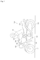
- Fig. 1 is a side view of the motorcycle 100 according to an embodiment of the invention, showing a state in which the airbag apparatus 120 is mounted to the motorcycle 100.
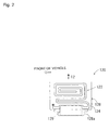
- Fig. 2 shows the structure of the airbag apparatus 120 in Fig. 1.
- the motorcycle 100 of the embodiment is an example of "a vehicle” or "a motorcycle” of the invention.
- the motorcycle 100 is what is called a touring motorcycle and mainly comprises a body frame 101 including an engine and a main frame; a seat 103 that a rider R can straddle; handlebars 104; a front wheel 111; and a rear wheel 112.
- a region above the body frame 101 of the motorcycle 100 and in front of the rider R is specified as an occupant restraining region 130 in the event of a frontal collision of the motorcycle 100.
- the "frontal collision” in the embodiment broadly includes that the motorcycle 100 collides with a front object (not shown for convenience sake).
- the "occupant restraining region 130" of the embodiment corresponds to "an occupant retraining region” of the invention, which is defined as a space extending in the direction of the forward movement of the rider R and for restraining the rider R who is flung ahead of the motorcycle 100 by a kinetic energy during a frontal collision.
- the airbag apparatus 120 is disposed at the rear of a fuel tank 105 behind the front portion 102. Particularly, the airbag apparatus 120 of the embodiment is disposed so as to face the occupant restraining region 130 for the rider R.
- the airbag apparatus 120 of the embodiment corresponds to "an airbag apparatus" of the invention.
- the airbag apparatus 120 of Fig. 1 mainly includes a retainer 128 serving as an airbag housing; an airbag 122 housed in the retainer 128 in a predetermined folded condition; and an inflator 129 housed in an inflator housing 128a of the retainer 128 and feeding expansion gas into the airbag 122 so that the airbag 122 deploys from the retainer 128.
- the airbag 122 corresponds to "an airbag" of the invention.
- the direction of the expansion (deployment) of the airbag 122 is indicated by an arrow 12.
- Fig. 3 is a diagram showing a state in which the airbag 122 starts to deploy, as viewed from the side of the vehicle.
- Fig. 4 is a diagram showing a state in which the airbag 122 has completed the inflation, as viewed from the side of the vehicle.
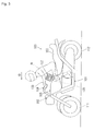
- Fig. 5 is a diagram showing a state in which the inflated airbag 122 restrains the rider R, as viewed from the side of the vehicle.
- Fig. 6 is a diagram showing a state in which the inflated airbag 122 restrains the rider R, as viewed from the front of the vehicle.
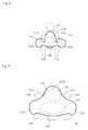
- Fig. 7 is an enlarged view of the airbag 122 in Fig. 6.
- Fig. 8 is a diagram showing a state in which the inflated airbag 122 restrains the rider R, as viewed from the back of the vehicle.
- Fig. 9 is a diagram showing a state in which the rider is restrained during pitching, as viewed from the side of the vehicle.
- the inflator 129 is activated to start the inflation (deployment) of the airbag 122 in a predetermined direction from the airbag apparatus 120. Since expansion gas is continuously fed into the airbag 122, the airbag 122 is expanded in sequence from the retainer 128.
- the airbag 122 is completely deployed.
- the expanded airbag 122 locally fills the vertical region (along the height of the occupant) of the occupant restraining region 130.
- the airbag 122 of the embodiment is not widely deployed across the occupant restraining region 130 but is deployed convergently to a desired local portion of the regions of the occupant's body.
- the inflated airbag 122 effectively restrains the rider R, who is moved into a forward-bent posture, from the front, side, and above, because the airbag 122 is disposed in the direction of the movement of the rider R, as shown in Fig. 5.
- the airbag 122 of the embodiment is constructed as a single airbag in which at least a first airbag portion 122a, a second airbag portion 122b, and an interference preventing portion 122c are combined into one.
- the airbag 122 is constructed so as to come into the shape shown in Fig. 7 when deployed, as viewed from the front of the vehicle.
- the construction may be achieved by devising the shape of the cutting of an airbag ground fabric, or alternatively, by stitching a tether or the like that connects the inner walls together into the airbag 122.
- the first airbag portion 122a of the airbag 122 is constructed as a portion which deploys locally around the lumbar part of the rider R (a region 132 in Fig. 7) in the occupant restraining region 130 in front of the rider R.
- the first airbag portion 122a corresponds to "a first airbag portion" of the invention.
- the first airbag portion 122a has the function of deploying above the knees (legs) of the rider R to restrain the lumbar part of the rider R during the deployment and to retain the thighs of the rider R from above.
- the restraint of at least the lumbar part that is one of regions effective in retraining the rider R, can ensure the prevention of the upward movement of the rider R during a collision and also during pitching or the like.
- two portions on the lower surface of the first airbag portion 122a interfere with the regions corresponding to the thighs of the rider R (regions 138 and 138 in Fig. 7). This arrangement can ensure the prevention of the upward movement of the rider R during the frontal collision of the vehicle.
- the second airbag portion 122b of the airbag 122 is constructed as a portion which deploys locally around the chest of the rider R (a region 134 in Fig. 7) in the occupant restraining region 130 in front of the rider R.
- the second airbag portion 122b corresponds to "a second airbag portion" of the invention.
- the second airbag portion 122b has the function of restraining the chest of the rider R during the deployment.
- the restraint of at least the chest that is one of the regions effective in retraining the rider R, can ensure the prevention of the forward movement of the rider R during a frontal collision.
- the interference preventing portion 122c of the airbag 122 has the function of preventing interference with the arms of the rider R at the boundary between the first airbag portion 122a and the second airbag portion 122b.
- the interference preventing portion 122c has a structure in which two portions at the boundary between the first airbag portion 122a and the second airbag portion 122b are recessed toward the center of the airbag 122 so as to minimize the interference with the regions corresponding to the arms of the rider R (regions 136 and 136 in Fig. 7).
- the interference preventing portion 122c corresponds to "an interference preventing portion" of the invention.
- the function of preventing interference with the arms by the interference preventing portion 122c includes a structure in which the interference preventing portion 122c does not come into contact with the arms of the rider R at all and a structure in which the interference preventing portion 122c comes into contact with the arms of the rider R with relatively small force (so as not to push up the arms strongly).
- the interference preventing portion 122c has only to prevent the arms of the rider R from being pushed up strongly by the deployed airbag 122 in the embodiment.
- the interference of the first airbag portion 122a and the second airbag portion 122b with the arms of the rider R can be prevented by the interference preventing portion 122c directly after the occurrence of a frontal collision of the vehicle. Due to this arrangement of the interference preventing portion 122c, the original purpose of the airbag 122, that is the restraint of the rider R who is moving ahead of the vehicle (also in an upper front direction) by the first airbag portion 122a and the second airbag portion 122b in a frontal collision, can be prevented from being obstructed by the interference with the arms of the rider R.
- the motorcycle 100 may pitch by the energy of the motorcycle 100 in a frontal collision.
- the rider R can be kept under restraint by the inflated airbag 122, as shown in Fig. 9.
- the first airbag portion 122a of the airbag 122 retains from above the thighs of the rider R who is moving upward in the direction of an arrow 14. Accordingly, the thighs are caught by the inflated airbag 122.
- the airbag 122 effectively and surely restrains the rider R from above when the vehicle pitches.
- the interference of the first airbag portion 122a and the second airbag portion 122b with the arms of the rider R can be continuously prevented by the interference preventing portion 122c directly after the occurrence of the frontal collision and the succeeding pitching.
- the arrangement of the interference preventing portion 122c can also maintain the original purpose of the airbag 122, that is the restraint of the rider R by the first airbag portion 122a and the second airbag portion 122b during a series of forward movements (including a movement in an upper front direction) of the rider R directly after the vehicle collision.
- the embodiment can increase the occupant retaining performance during an accident not by widely deploying the airbag 122 across the occupant restraining region 130 in front of the rider R but by devising the shape and arrangement of the airbag 122 of the airbag apparatus 120.
- the embodiment is based on a strategical technical principle that only important regions of the body of the rider R are locally (intensively) restrained by the airbag 122.
- the embodiment is constructed so as to minimize the interference between the airbag 122 and the arms of the rider R during deployment.
- the airbag 122 and the airbag apparatus 120 can be reduced in size, and in addition, high occupant restraining performance can be maintained even with the compact airbag 122 in the same way as the case in which an airbag is widely deployed across the occupant restraining region 130.
- the airbag 122 of the embodiment is adapted such that the first airbag portion 122a restrains at least the lumbar part that is one of the important regions effective in restraining the rider; the second airbag portion 122b restrains at least the chest that is one of the important regions effective in restraining the rider; and the interference preventing portion 122c prevents the arms of the rider R from being pushed up strongly in the frontal collision.
- This arrangement enables the rider R to be restrained directly after the occurrence of the frontal collision to the succeeding pitching, thus increasing the retaining performance for the rider R.
- the airbag 122 is deployed locally.
- This arrangement is effective in reducing the size of the airbag 122, the retainer 128 for housing the airbag 122 and so on in comparison with a structure in which an airbag is widely deployed across the occupant restraining region 130.
- the airbag 122 for example, may be locally deployed in a region corresponding to the shoulders of the rider R.
- This arrangement has a limitation in reducing the size of the airbag because the airbag must be deployed widely.
- the embodiment has a structure in which the airbag 122 is deployed toward a region close to the mounted position of the airbag apparatus 120. This arrangement can reduce the size of the airbag 122, the retainer 128 and so on, while maintaining the occupant restraining performance.
- the invention may be constructed in such a manner that the airbag 122 rounds to the back of the lumbar part of the rider R to restrain the rider.
- the invention may be applied to other types of motorcycle such as motor scooters having a space between the handlebars and the seat and to vehicles other than the motorcycle 100.
- the position of the airbag apparatus 120 may be varied as appropriate provided that the airbag 122 deploys into a desired region in a vehicle collision.
- the airbag apparatus 120 may be disposed more to the front than that shown in Fig. 1.
- Motor scooters may have the airbag apparatus 120 (the retainer 128) under the seat or at the front of the vehicle body.
- the invention may have separate airbags having the function of the first airbag portion 122a and the function of the second airbag portion 122b, respectively.
- the invention may adopt a structure in which the single airbag 122 is combined with another airbag.
Abstract
Description
- The present invention relates to a technique of constructing an airbag apparatus to be mounted to a motorcycle.
- There have been various known techniques of restraining occupants of motorcycles with airbag apparatuses. One of the known techniques is such that, when a motorcycle collides head-on, an airbag housed in a casing mounted to the body frame is inflated by expansion gas to restrain an occupant (e.g., refer to
Japanese Unexamined Patent Application Publication No. 2002-137777 - The present invention is made in view of the above problem. Accordingly, it is an object of the invention to provide a technique of increasing occupant restraining performance of an airbag apparatus to be mounted to a motorcycle in a vehicle accident while reducing the size of an airbag.
- According to the invention, this object is achieved by an airbag apparatus as defined in claim 1 and a motorcycle as defined in claim 7. The dependent claims define preferred and advantageous embodiments of the invention.
- Typically, the invention can be applied in constructing airbag apparatuses to be mounted to various motorcycles. In this specification, a motorcycle, a typical example of vehicles, includes various saddle-type vehicles that an occupant straddles, such as touring motorcycles having a fuel tank in front of an occupant seat and motor scooters having a space between an occupant seat and a handlebar-supporting head pipe. In addition to the motorcycles, the "motorcycle" includes vehicles that occupants straddle and having three or more running wheels (e.g., three-wheel motorbikes for use in home delivery service and three- or four-wheel buggies for bad roads) and vehicles that occupants ride on and running by sledges or caterpillars, such as snow mobiles.
- According to the invention, the airbag apparatus includes at least an airbag. The airbag deploys to restrain an occupant when expansion gas is fed into the interior by an expansion gas feeding device such as an inflator during a frontal collision of a vehicle. Particularly, the airbag of the invention includes at least a first airbag portion, a second airbag portion, and an interference preventing portion. The invention may be such that the first airbag portion and the second airbag portion are combined into a single airbag, or alternatively, the first airbag portion and the second airbag portion are formed into separate airbags.
- The first airbag portion of the airbag is constructed so as to deploy locally into the region of an occupant restraining region which corresponds to the lumbar part of the occupant. The first airbag portion deploys above the knees (legs) of a rider to restrain the lumbar part of the rider and to retain the thighs of the rider from above during the deployment. Since the lumbar part of the rider substantially agrees with the center of gravity of the rider, the restraint of at least the lumbar part, that is one of regions effective in retraining the rider, can surely prevent the upward movement of the rider during a collision and also during pitching or the like. For the retaining of the thighs of the rider, the lower surface of the first airbag portion interferes with the regions corresponding to the thighs of the rider. This arrangement surely prevents the upward movement of the rider during a frontal collision of the vehicle with the first airbag portion that comes into contact with the upper surface of the thighs of the rider.
- The second airbag portion of the airbag is constructed so as to deploy locally into the region of the occupant restraining region which corresponds to the chest of the rider. The second airbag portion has the function of restraining the chest of the rider during the deployment. Thus, the restraint of at least the chest, that is one of the regions effective in retraining the rider, can surely prevent the forward movement of the rider during a frontal collision. In the present invention, the first airbag portion and the second airbag portion of the deployed airbag are the local portions in the vertical direction of the vehicle body (the direction of the height of the occupant) in the occupant restraining region. Thus the airbag of the invention does not deploy across the occupant restraining region in a frontal collision, but deploys convergently into a desired local vertical region of the vehicle body.
- The interference preventing portion of the airbag is constructed as a portion preventing the interference of the first airbag portion and the second piston portion with the arms of the rider. Here the arrangement for "preventing the interference with the arms by the interference preventing portion" includes a structure in which the interference preventing portion does not come into contact with the arms of the rider at all and a structure in which the interference preventing portion comes into contact with the arms of the rider with relatively small force (so as not to push up the arms strongly). In a word, the interference preventing portion of the present invention may have only to prevent the arms of the rider from being pushed up strongly by the deployed airbag. This arrangement can prevent the original purpose of the airbag from being obstructed by the interference with rider's arms.
- The interference preventing portion can be provided by devising the shape of the cutting of an airbag ground fabric, or alternatively, by stitching a tether or the like that interconnects the inner walls to the airbag.
- In the invention, the time (timing) the prevention of the interference is achieved by the interference preventing portion may be directly after the occurrence of the frontal collision, or alternatively, during the succeeding action. This arrangement in which the interference between the airbag and the arms is prevented directly after the occurrence of the frontal collision can prevent the original restraining performance of the airbag from being obstructed by the interference with the arms of the rider. The original restraining performance is to restrain a rider who is moving ahead of the vehicle (also into a upper front region) by the first airbag portion and the second airbag portion in a frontal collision. Also, the arrangement in which the interference between the airbag and the arms is continuously prevented during the succeeding action directly after the occurrence of the frontal collision can maintain the original restraining performance by the first airbag portion and the second airbag portion during a series of the forward movement (also the movement into an upper front region) of the rider.
- With the arrangement of the airbag apparatus according to the invention, there is no need to deploy the airbag widely across the occupant restraining region in front of the occupant. Accordingly, the airbag and the airbag apparatus that houses the airbag can be reduced in size. Also, since the interference between the first airbag portion and the second airbag portion and the arms of the occupant can be prevented by the interference preventing portion, occupant restraining performance during a vehicle accident can be increased with a compact airbag and airbag apparatus.
- The airbag apparatus may be such that the airbag of the invention is a single airbag in which the first airbag portion and the second airbag portion are integrated, and the interference preventing portion is formed between the first airbag portion and the second airbag portion. Typically, the boundary between the first airbag portion and the second airbag portion is recessed toward the center of the airbag so as to minimize the interference with the regions corresponding to the arms of the occupant.
- Accordingly, an occupant restraining performance can be increased with a compact airbag and airbag apparatus, and the structure of the airbag can be simplified.
- In addition, a motorcycle with an airbag apparatus described above is provided according to the invention.
- Accordingly, the invention provides a motorcycle in which occupant restraining performance in a vehicle accident can be increased with a compact airbag and airbag apparatus.
- The airbag apparatus to be mounted to a motorcycle according to present invention is arranged in such a manner that only important regions of the body of an occupant are locally (convergently) restrained by the airbag and the interference between the airbag and the arms during the deployment of the airbag is prevented. This arrangement enables the occupant restraining performance in a vehicle accident to be increased while reducing the size of the airbag.
- In this regard, a preferred range for the extension of the airbag in a direction of the height of the motorcycle rider is 500-600 mm above the seat surface, while the second airbag portion preferably extends 600-900 mm in a lateral direction of the motorcycle (depending on the riding posture of the motorcycle rider, which in turn varies depending on the motorcycle type such as touring type, scooter type etc).
-
- Fig. 1 is a side view of a motorcycle according to an embodiment of the invention, showing a state in which an airbag apparatus is mounted to the motorcycle.
- Fig. 2 shows the structure of the airbag apparatus in Fig. 1.
- Fig. 3 is a diagram showing a state in which an airbag starts to inflate, as viewed from the side of the vehicle.
- Fig. 4 is a diagram showing a state in which the airbag has completed the inflation, as viewed from the side of the vehicle.
- Fig. 5 is a diagram showing a state in which the inflated airbag restrains a rider, as viewed from the side of the vehicle.
- Fig. 6 is a diagram showing a state in which the inflated airbag restrains the rider, as viewed from the front of the vehicle.
- Fig. 7 is an enlarged view of the airbag shown in Fig. 6.
- Fig. 8 is a diagram showing a state in which the inflated airbag restrains the rider, as viewed from the back of the vehicle.
- Fig. 9 is a diagram showing a state in which the rider is restrained during pitching, as viewed from the side of the vehicle.
- An embodiment of the present invention will be described specifically with reference to the drawings. Referring first to Figs. 1 and 2, the entire structure of a
motorcycle 100 and the structure of anairbag apparatus 120 will be described. Fig. 1 is a side view of themotorcycle 100 according to an embodiment of the invention, showing a state in which theairbag apparatus 120 is mounted to themotorcycle 100. Fig. 2 shows the structure of theairbag apparatus 120 in Fig. 1. Themotorcycle 100 of the embodiment is an example of "a vehicle" or "a motorcycle" of the invention. - Referring to Fig. 1, the
motorcycle 100 is what is called a touring motorcycle and mainly comprises abody frame 101 including an engine and a main frame; aseat 103 that a rider R can straddle;handlebars 104; afront wheel 111; and arear wheel 112. - A region above the
body frame 101 of themotorcycle 100 and in front of the rider R is specified as anoccupant restraining region 130 in the event of a frontal collision of themotorcycle 100. The "frontal collision" in the embodiment broadly includes that themotorcycle 100 collides with a front object (not shown for convenience sake). The "occupant restraining region 130" of the embodiment corresponds to "an occupant retraining region" of the invention, which is defined as a space extending in the direction of the forward movement of the rider R and for restraining the rider R who is flung ahead of themotorcycle 100 by a kinetic energy during a frontal collision. - A
front portion 102 of thebody frame 101, at the front of the vehicle, includes a headlight, various meters, switches, and the like. Theairbag apparatus 120 is disposed at the rear of afuel tank 105 behind thefront portion 102. Particularly, theairbag apparatus 120 of the embodiment is disposed so as to face theoccupant restraining region 130 for the rider R. Theairbag apparatus 120 of the embodiment corresponds to "an airbag apparatus" of the invention. - Referring to Fig. 2, the
airbag apparatus 120 of Fig. 1 mainly includes aretainer 128 serving as an airbag housing; anairbag 122 housed in theretainer 128 in a predetermined folded condition; and an inflator 129 housed in aninflator housing 128a of theretainer 128 and feeding expansion gas into theairbag 122 so that theairbag 122 deploys from theretainer 128. Theairbag 122 corresponds to "an airbag" of the invention. In Fig. 2, the direction of the expansion (deployment) of theairbag 122 is indicated by anarrow 12. - The operation of the
airbag apparatus 120 with this arrangement will be described with reference to Figs. 3 to 9. Fig. 3 is a diagram showing a state in which theairbag 122 starts to deploy, as viewed from the side of the vehicle. Fig. 4 is a diagram showing a state in which theairbag 122 has completed the inflation, as viewed from the side of the vehicle. Fig. 5 is a diagram showing a state in which theinflated airbag 122 restrains the rider R, as viewed from the side of the vehicle. Fig. 6 is a diagram showing a state in which theinflated airbag 122 restrains the rider R, as viewed from the front of the vehicle. Fig. 7 is an enlarged view of theairbag 122 in Fig. 6. Fig. 8 is a diagram showing a state in which theinflated airbag 122 restrains the rider R, as viewed from the back of the vehicle. Fig. 9 is a diagram showing a state in which the rider is restrained during pitching, as viewed from the side of the vehicle. - Referring to Fig. 3, when the
motorcycle 100 comes into a collision in the traveling direction, the rider R is moving (being flung) ahead of the motorcycle 100 (e.g., in the direction of anarrow 10 in Fig. 3). In the embodiment, upon detection of the frontal collision, theinflator 129 is activated to start the inflation (deployment) of theairbag 122 in a predetermined direction from theairbag apparatus 120. Since expansion gas is continuously fed into theairbag 122, theairbag 122 is expanded in sequence from theretainer 128. - Thus, as shown in Fig. 4, the
airbag 122 is completely deployed. In this state, the expandedairbag 122 locally fills the vertical region (along the height of the occupant) of theoccupant restraining region 130. As will be described later, theairbag 122 of the embodiment is not widely deployed across theoccupant restraining region 130 but is deployed convergently to a desired local portion of the regions of the occupant's body. - When the
motorcycle 100 collides head-on, and the rider R is moving forward by the kinetic energy of the collision, theinflated airbag 122 effectively restrains the rider R, who is moved into a forward-bent posture, from the front, side, and above, because theairbag 122 is disposed in the direction of the movement of the rider R, as shown in Fig. 5. - The specific operation of the
airbag 122 will be described with reference to Figs. 6 to 8. - As shown in Figs. 6 to 8, the
airbag 122 of the embodiment is constructed as a single airbag in which at least afirst airbag portion 122a, asecond airbag portion 122b, and aninterference preventing portion 122c are combined into one. Particularly, theairbag 122 is constructed so as to come into the shape shown in Fig. 7 when deployed, as viewed from the front of the vehicle. The construction may be achieved by devising the shape of the cutting of an airbag ground fabric, or alternatively, by stitching a tether or the like that connects the inner walls together into theairbag 122. - As shown in Fig. 7, the
first airbag portion 122a of theairbag 122 is constructed as a portion which deploys locally around the lumbar part of the rider R (aregion 132 in Fig. 7) in theoccupant restraining region 130 in front of the rider R. Thefirst airbag portion 122a corresponds to "a first airbag portion" of the invention. Thefirst airbag portion 122a has the function of deploying above the knees (legs) of the rider R to restrain the lumbar part of the rider R during the deployment and to retain the thighs of the rider R from above. Since the lumbar part of the rider R substantially agrees with the center of gravity of the rider R, the restraint of at least the lumbar part, that is one of regions effective in retraining the rider R, can ensure the prevention of the upward movement of the rider R during a collision and also during pitching or the like. For the retaining of the thighs of the rider R, two portions on the lower surface of thefirst airbag portion 122a interfere with the regions corresponding to the thighs of the rider R (regions - The
second airbag portion 122b of theairbag 122 is constructed as a portion which deploys locally around the chest of the rider R (aregion 134 in Fig. 7) in theoccupant restraining region 130 in front of the rider R. Thesecond airbag portion 122b corresponds to "a second airbag portion" of the invention. Thesecond airbag portion 122b has the function of restraining the chest of the rider R during the deployment. Thus, the restraint of at least the chest, that is one of the regions effective in retraining the rider R, can ensure the prevention of the forward movement of the rider R during a frontal collision. - The
interference preventing portion 122c of theairbag 122 has the function of preventing interference with the arms of the rider R at the boundary between thefirst airbag portion 122a and thesecond airbag portion 122b. Specifically, theinterference preventing portion 122c has a structure in which two portions at the boundary between thefirst airbag portion 122a and thesecond airbag portion 122b are recessed toward the center of theairbag 122 so as to minimize the interference with the regions corresponding to the arms of the rider R (regions interference preventing portion 122c corresponds to "an interference preventing portion" of the invention. Here the function of preventing interference with the arms by theinterference preventing portion 122c includes a structure in which theinterference preventing portion 122c does not come into contact with the arms of the rider R at all and a structure in which theinterference preventing portion 122c comes into contact with the arms of the rider R with relatively small force (so as not to push up the arms strongly). In a word, theinterference preventing portion 122c has only to prevent the arms of the rider R from being pushed up strongly by the deployedairbag 122 in the embodiment. - According to the embodiment, the interference of the
first airbag portion 122a and thesecond airbag portion 122b with the arms of the rider R can be prevented by theinterference preventing portion 122c directly after the occurrence of a frontal collision of the vehicle. Due to this arrangement of theinterference preventing portion 122c, the original purpose of theairbag 122, that is the restraint of the rider R who is moving ahead of the vehicle (also in an upper front direction) by thefirst airbag portion 122a and thesecond airbag portion 122b in a frontal collision, can be prevented from being obstructed by the interference with the arms of the rider R. - The
motorcycle 100 may pitch by the energy of themotorcycle 100 in a frontal collision. In this case, the rider R can be kept under restraint by theinflated airbag 122, as shown in Fig. 9. Particularly, thefirst airbag portion 122a of theairbag 122 retains from above the thighs of the rider R who is moving upward in the direction of an arrow 14. Accordingly, the thighs are caught by theinflated airbag 122. Thus theairbag 122 effectively and surely restrains the rider R from above when the vehicle pitches. - According to the embodiment, the interference of the
first airbag portion 122a and thesecond airbag portion 122b with the arms of the rider R can be continuously prevented by theinterference preventing portion 122c directly after the occurrence of the frontal collision and the succeeding pitching. The arrangement of theinterference preventing portion 122c can also maintain the original purpose of theairbag 122, that is the restraint of the rider R by thefirst airbag portion 122a and thesecond airbag portion 122b during a series of forward movements (including a movement in an upper front direction) of the rider R directly after the vehicle collision. - As described above, the embodiment can increase the occupant retaining performance during an accident not by widely deploying the
airbag 122 across theoccupant restraining region 130 in front of the rider R but by devising the shape and arrangement of theairbag 122 of theairbag apparatus 120. In other words, the embodiment is based on a strategical technical principle that only important regions of the body of the rider R are locally (intensively) restrained by theairbag 122. Also, the embodiment is constructed so as to minimize the interference between theairbag 122 and the arms of the rider R during deployment. With this arrangement, theairbag 122 and theairbag apparatus 120 can be reduced in size, and in addition, high occupant restraining performance can be maintained even with thecompact airbag 122 in the same way as the case in which an airbag is widely deployed across theoccupant restraining region 130. - Particularly, the
airbag 122 of the embodiment is adapted such that thefirst airbag portion 122a restrains at least the lumbar part that is one of the important regions effective in restraining the rider; thesecond airbag portion 122b restrains at least the chest that is one of the important regions effective in restraining the rider; and theinterference preventing portion 122c prevents the arms of the rider R from being pushed up strongly in the frontal collision. This arrangement enables the rider R to be restrained directly after the occurrence of the frontal collision to the succeeding pitching, thus increasing the retaining performance for the rider R. - According to the embodiment, the
airbag 122 is deployed locally. This arrangement is effective in reducing the size of theairbag 122, theretainer 128 for housing theairbag 122 and so on in comparison with a structure in which an airbag is widely deployed across theoccupant restraining region 130. Theairbag 122, for example, may be locally deployed in a region corresponding to the shoulders of the rider R. This arrangement, however, has a limitation in reducing the size of the airbag because the airbag must be deployed widely. In contrast, the embodiment has a structure in which theairbag 122 is deployed toward a region close to the mounted position of theairbag apparatus 120. This arrangement can reduce the size of theairbag 122, theretainer 128 and so on, while maintaining the occupant restraining performance. - It is to be understood that the invention is not limited to the above-described embodiment but various applications and modifications may be made. For example, the following applications are possible.
- While the embodiment is such that the deployed
airbag 122 restrains the vicinity of the lumbar part, chest, and legs of the rider R from the front, side, and above, the invention may be constructed in such a manner that theairbag 122 rounds to the back of the lumbar part of the rider R to restrain the rider. - While the embodiment has been described with reference to the
touring motorcycle 100 of what is called a touring type, the invention may be applied to other types of motorcycle such as motor scooters having a space between the handlebars and the seat and to vehicles other than themotorcycle 100. - While the embodiment has been described about the case in which the airbag apparatus 120 (the retainer 128) is disposed at the rear of the
fuel tank 105, the position of the airbag apparatus 120 (the retainer 128) may be varied as appropriate provided that theairbag 122 deploys into a desired region in a vehicle collision. For example, theairbag apparatus 120 may be disposed more to the front than that shown in Fig. 1. Motor scooters may have the airbag apparatus 120 (the retainer 128) under the seat or at the front of the vehicle body. - While the embodiment has been described about the case in which the
single airbag 122 in which thefirst airbag portion 122a and thesecond airbag portion 122b are combined is used, the invention may have separate airbags having the function of thefirst airbag portion 122a and the function of thesecond airbag portion 122b, respectively. Alternatively, the invention may adopt a structure in which thesingle airbag 122 is combined with another airbag.
Claims (9)
- An airbag apparatus to be mounted to a motorcycle (100), the airbag apparatus (120) comprising:an airbag (122) that restrains an occupant (R) by deploying into an occupant restraining region (130) in front of the occupant (R) in a frontal collision of the motorcycle (100), whereinthe airbag (122) includes a first airbag portion (122a) that deploys into a region (132) of the occupant restraining region (130) around the lumbar part of the occupant (R); a second airbag portion (122b) that deploys into a region (134) of the occupant restraining region (130) around the chest of the occupant (R); and an interference preventing portion (122c) that prevents interference of the first airbag portion (122a) and the second airbag portion (122b) with the arms of the occupant (R).
- The airbag apparatus according to Claim 1, wherein the first airbag portion (122a) deploys above thighs of the occupant (R) in order to retain the thighs of the occupant (R) from moving above.
- The airbag apparatus according to Claim 1 or Claim 2, wherein the first airbag portion (122a) and the second airbag portion (122b) are arranged in a direction of a height of the occupant (R) in the occupant restraining region (130) such that the airbag (122) does not deploy across the occupant restraining region (130).
- The airbag apparatus according to any one of Claims 1-3, wherein the interference preventing portion (122c) is provided by connecting a tether that interconnects inner walls of the airbag (122).
- The airbag apparatus according to any one of Claims 1-4, wherein the interference preventing portion (122c) has a structure in which two portions at a boundary between the first airbag portion (122a) and the second airbag portion (122b) are recessed toward a center of the airbag (122).
- The airbag apparatus according to any one of Claims 1-5, wherein
the airbag (122) is constructed as a single airbag in which the first airbag portion (122a) and the second airbag portion (122b) are integrated, and the interference preventing portion (122c) is formed between the first airbag portion (122a) and the second airbag portion (122b). - A motorcycle with an airbag apparatus (120) in which an airbag (122) deploys in a frontal collision, wherein
the motorcycle (100) has the airbag apparatus (120) according to any one of Claims 1-6. - The motorcycle according to Claim 7,
wherein the airbag (122) is designed such that an extension of the airbag (122) in a direction of the height of a motorcycle rider is 500 mm - 600 mm above a seat surface of the motorcycle. - The motorcycle according to Claim 7 or Claim 8,
wherein the airbag (122) is designed such that an extension of the second airbag portion (122b) in a lateral direction of the motorcycle is 600 mm - 900 mm.
Applications Claiming Priority (1)
| Application Number | Priority Date | Filing Date | Title |
|---|---|---|---|
| JP2005259974A JP2007069779A (en) | 2005-09-07 | 2005-09-07 | Air bag device and motorcycle with air bag device |
Publications (3)
| Publication Number | Publication Date |
|---|---|
| EP1762477A2 true EP1762477A2 (en) | 2007-03-14 |
| EP1762477A3 EP1762477A3 (en) | 2007-04-18 |
| EP1762477B1 EP1762477B1 (en) | 2010-03-31 |
Family
ID=37460046
Family Applications (1)
| Application Number | Title | Priority Date | Filing Date |
|---|---|---|---|
| EP06018337A Expired - Fee Related EP1762477B1 (en) | 2005-09-07 | 2006-09-01 | Airbag apparatus and motorcycle with airbag apparatus |
Country Status (5)
| Country | Link |
|---|---|
| US (1) | US7562900B2 (en) |
| EP (1) | EP1762477B1 (en) |
| JP (1) | JP2007069779A (en) |
| CN (1) | CN1927646A (en) |
| DE (1) | DE602006013242D1 (en) |
Families Citing this family (7)
| Publication number | Priority date | Publication date | Assignee | Title |
|---|---|---|---|---|
| CN101801734B (en) * | 2007-09-16 | 2014-05-28 | 丰田自动车东日本株式会社 | Airbag |
| JP2009196410A (en) * | 2008-02-19 | 2009-09-03 | Honda Motor Co Ltd | Motorcycle |
| JP5223115B2 (en) * | 2009-01-29 | 2013-06-26 | 豊田合成株式会社 | Airbag device for motorcycle |
| WO2021199333A1 (en) * | 2020-03-31 | 2021-10-07 | 本田技研工業株式会社 | Straddle-type vehicle |
| WO2021199361A1 (en) * | 2020-03-31 | 2021-10-07 | 本田技研工業株式会社 | Saddle-ride type vehicle |
| EP4129808A4 (en) * | 2020-03-31 | 2023-04-26 | Honda Motor Co., Ltd. | Saddle-ride type vehicle |
| DE102021112849A1 (en) * | 2021-05-18 | 2022-11-24 | Autoliv Development Ab | AIRBAG ARRANGEMENT FOR A DRIVER-OPERATABLE VEHICLE |
Citations (1)
| Publication number | Priority date | Publication date | Assignee | Title |
|---|---|---|---|---|
| JPH1071911A (en) | 1996-08-30 | 1998-03-17 | Honda Motor Co Ltd | Vehicular air bag device |
Family Cites Families (15)
| Publication number | Priority date | Publication date | Assignee | Title |
|---|---|---|---|---|
| US3642303A (en) * | 1970-02-13 | 1972-02-15 | Gen Motors Corp | Vehicle occupant restraint system |
| JP3316315B2 (en) * | 1994-09-06 | 2002-08-19 | タカタ株式会社 | Airbag device for passenger seat |
| JP3685872B2 (en) * | 1996-06-11 | 2005-08-24 | 本田技研工業株式会社 | Pressure adjusting device for air bag in motorcycle |
| JP3592447B2 (en) * | 1996-07-25 | 2004-11-24 | 本田技研工業株式会社 | Airbag device for motorcycles |
| JP4465855B2 (en) | 2000-11-01 | 2010-05-26 | 豊田合成株式会社 | Saddle-type vehicle airbag device |
| JP3807258B2 (en) * | 2001-06-27 | 2006-08-09 | 豊田合成株式会社 | Saddle-type vehicle airbag device |
| US6786505B2 (en) * | 2001-08-17 | 2004-09-07 | Takata Corporation | Airbag device |
| JP4310115B2 (en) * | 2002-03-06 | 2009-08-05 | 本田技研工業株式会社 | Scooter type motorcycle with airbag device |
| JP4226259B2 (en) * | 2002-04-05 | 2009-02-18 | 本田技研工業株式会社 | Airbag device for small vehicles |
| JP4084592B2 (en) * | 2002-04-18 | 2008-04-30 | 本田技研工業株式会社 | Airbag device in scooter type vehicle |
| JP4119155B2 (en) * | 2002-04-22 | 2008-07-16 | 本田技研工業株式会社 | Airbag device for small vehicle |
| DE10223830A1 (en) * | 2002-05-28 | 2004-01-08 | Takata Corp. | Multi-part gas bag blank for an airbag of an occupant protection device for motor vehicles and method for producing an airbag from the airbag blank |
| JP2004314811A (en) * | 2003-04-16 | 2004-11-11 | Takata Corp | Airbag device, and motorcycle with the airbag device |
| JP4388313B2 (en) * | 2003-06-19 | 2009-12-24 | タカタ株式会社 | Airbag device, motorcycle with airbag device |
| DE602005010341D1 (en) * | 2004-08-09 | 2008-11-27 | Nissan Motor | Vehicle occupant restraint system and method |
-
2005
- 2005-09-07 JP JP2005259974A patent/JP2007069779A/en active Pending
-
2006
- 2006-09-01 EP EP06018337A patent/EP1762477B1/en not_active Expired - Fee Related
- 2006-09-01 DE DE602006013242T patent/DE602006013242D1/en active Active
- 2006-09-07 CN CNA2006101517862A patent/CN1927646A/en active Pending
- 2006-09-07 US US11/470,692 patent/US7562900B2/en not_active Expired - Fee Related
Patent Citations (1)
| Publication number | Priority date | Publication date | Assignee | Title |
|---|---|---|---|---|
| JPH1071911A (en) | 1996-08-30 | 1998-03-17 | Honda Motor Co Ltd | Vehicular air bag device |
Also Published As
| Publication number | Publication date |
|---|---|
| DE602006013242D1 (en) | 2010-05-12 |
| CN1927646A (en) | 2007-03-14 |
| EP1762477A3 (en) | 2007-04-18 |
| JP2007069779A (en) | 2007-03-22 |
| EP1762477B1 (en) | 2010-03-31 |
| US7562900B2 (en) | 2009-07-21 |
| US20070052213A1 (en) | 2007-03-08 |
Similar Documents
| Publication | Publication Date | Title |
|---|---|---|
| JP4636935B2 (en) | Airbag device, saddle riding type vehicle with airbag device | |
| US7044499B2 (en) | Air bag apparatus for motorcycle, method of manufacturing air bag apparatus for motorcycle, and motorcycle with air bag apparatus | |
| EP1762477B1 (en) | Airbag apparatus and motorcycle with airbag apparatus | |
| US7588264B2 (en) | Airbag system and motorcycle with airbag system | |
| JP6357677B2 (en) | Airbag device for saddle riding type vehicle | |
| US7331600B2 (en) | Airbag apparatus, motorcycle with airbag apparatus, and method of manufacturing airbag apparatus | |
| JP2003327183A (en) | Air bag device for motorcycle, manufacturing method of air bag device for motorcycle and motorcycle with air bag device | |
| EP1813519B1 (en) | Motorcycle with airbag system | |
| US7686328B2 (en) | Motorcycle airbag system and motorcycle | |
| JP2008222163A (en) | Airbag device for motorcycle | |
| JP4181843B2 (en) | Airbag device, motorcycle with airbag device, and method of manufacturing airbag device | |
| JP4606243B2 (en) | Airbag device, motorcycle with airbag device | |
| JP4671754B2 (en) | Airbag device, motorcycle with airbag device | |
| KR20220123119A (en) | Airbag device for motorcycles | |
| JP4051155B2 (en) | Airbag device for automobile | |
| JP2023085131A (en) | Air bag device for autobicycle |
Legal Events
| Date | Code | Title | Description |
|---|---|---|---|
| PUAI | Public reference made under article 153(3) epc to a published international application that has entered the european phase |
Free format text: ORIGINAL CODE: 0009012 |
|
| AK | Designated contracting states |
Kind code of ref document: A2 Designated state(s): AT BE BG CH CY CZ DE DK EE ES FI FR GB GR HU IE IS IT LI LT LU LV MC NL PL PT RO SE SI SK TR |
|
| AX | Request for extension of the european patent |
Extension state: AL BA HR MK YU |
|
| PUAL | Search report despatched |
Free format text: ORIGINAL CODE: 0009013 |
|
| AK | Designated contracting states |
Kind code of ref document: A3 Designated state(s): AT BE BG CH CY CZ DE DK EE ES FI FR GB GR HU IE IS IT LI LT LU LV MC NL PL PT RO SE SI SK TR |
|
| AX | Request for extension of the european patent |
Extension state: AL BA HR MK YU |
|
| RIC1 | Information provided on ipc code assigned before grant |
Ipc: B62J 27/00 20060101AFI20061207BHEP Ipc: B60R 21/231 20060101ALI20070312BHEP |
|
| 17P | Request for examination filed |
Effective date: 20070921 |
|
| 17Q | First examination report despatched |
Effective date: 20071025 |
|
| AKX | Designation fees paid |
Designated state(s): DE FR GB SE |
|
| GRAP | Despatch of communication of intention to grant a patent |
Free format text: ORIGINAL CODE: EPIDOSNIGR1 |
|
| GRAS | Grant fee paid |
Free format text: ORIGINAL CODE: EPIDOSNIGR3 |
|
| GRAA | (expected) grant |
Free format text: ORIGINAL CODE: 0009210 |
|
| AK | Designated contracting states |
Kind code of ref document: B1 Designated state(s): DE FR GB SE |
|
| REG | Reference to a national code |
Ref country code: GB Ref legal event code: FG4D |
|
| REF | Corresponds to: |
Ref document number: 602006013242 Country of ref document: DE Date of ref document: 20100512 Kind code of ref document: P |
|
| PG25 | Lapsed in a contracting state [announced via postgrant information from national office to epo] |
Ref country code: SE Free format text: LAPSE BECAUSE OF FAILURE TO SUBMIT A TRANSLATION OF THE DESCRIPTION OR TO PAY THE FEE WITHIN THE PRESCRIBED TIME-LIMIT Effective date: 20100331 |
|
| PLBE | No opposition filed within time limit |
Free format text: ORIGINAL CODE: 0009261 |
|
| STAA | Information on the status of an ep patent application or granted ep patent |
Free format text: STATUS: NO OPPOSITION FILED WITHIN TIME LIMIT |
|
| 26N | No opposition filed |
Effective date: 20110104 |
|
| REG | Reference to a national code |
Ref country code: FR Ref legal event code: ST Effective date: 20110531 |
|
| PG25 | Lapsed in a contracting state [announced via postgrant information from national office to epo] |
Ref country code: FR Free format text: LAPSE BECAUSE OF NON-PAYMENT OF DUE FEES Effective date: 20100930 |
|
| PGFP | Annual fee paid to national office [announced via postgrant information from national office to epo] |
Ref country code: DE Payment date: 20130829 Year of fee payment: 8 |
|
| PGFP | Annual fee paid to national office [announced via postgrant information from national office to epo] |
Ref country code: GB Payment date: 20130828 Year of fee payment: 8 |
|
| REG | Reference to a national code |
Ref country code: DE Ref legal event code: R119 Ref document number: 602006013242 Country of ref document: DE |
|
| GBPC | Gb: european patent ceased through non-payment of renewal fee |
Effective date: 20140901 |
|
| REG | Reference to a national code |
Ref country code: DE Ref legal event code: R119 Ref document number: 602006013242 Country of ref document: DE Effective date: 20150401 |
|
| PG25 | Lapsed in a contracting state [announced via postgrant information from national office to epo] |
Ref country code: DE Free format text: LAPSE BECAUSE OF NON-PAYMENT OF DUE FEES Effective date: 20150401 Ref country code: GB Free format text: LAPSE BECAUSE OF NON-PAYMENT OF DUE FEES Effective date: 20140901 |