EP1764034A2 - Implantable self-calibrating optical sensors - Google Patents
Implantable self-calibrating optical sensors Download PDFInfo
- Publication number
- EP1764034A2 EP1764034A2 EP06254869A EP06254869A EP1764034A2 EP 1764034 A2 EP1764034 A2 EP 1764034A2 EP 06254869 A EP06254869 A EP 06254869A EP 06254869 A EP06254869 A EP 06254869A EP 1764034 A2 EP1764034 A2 EP 1764034A2
- Authority
- EP
- European Patent Office
- Prior art keywords
- light
- light source
- intensity
- signal
- transmitted
- Prior art date
- Legal status (The legal status is an assumption and is not a legal conclusion. Google has not performed a legal analysis and makes no representation as to the accuracy of the status listed.)
- Granted
Links
- 230000003287 optical effect Effects 0.000 title description 9
- 238000005259 measurement Methods 0.000 claims abstract description 62
- QVGXLLKOCUKJST-UHFFFAOYSA-N atomic oxygen Chemical compound [O] QVGXLLKOCUKJST-UHFFFAOYSA-N 0.000 claims description 33
- 229910052760 oxygen Inorganic materials 0.000 claims description 33
- 239000001301 oxygen Substances 0.000 claims description 33
- 210000004369 blood Anatomy 0.000 claims description 28
- 239000008280 blood Substances 0.000 claims description 28
- 238000005534 hematocrit Methods 0.000 claims description 23
- 238000000034 method Methods 0.000 claims description 15
- 230000001225 therapeutic effect Effects 0.000 claims description 9
- 230000032683 aging Effects 0.000 claims description 5
- 230000003321 amplification Effects 0.000 claims 2
- 238000003199 nucleic acid amplification method Methods 0.000 claims 2
- 230000000638 stimulation Effects 0.000 description 38
- 230000002861 ventricular Effects 0.000 description 34
- 230000001746 atrial effect Effects 0.000 description 30
- 230000000747 cardiac effect Effects 0.000 description 21
- 238000002560 therapeutic procedure Methods 0.000 description 17
- 238000001514 detection method Methods 0.000 description 13
- 210000003748 coronary sinus Anatomy 0.000 description 12
- 238000012545 processing Methods 0.000 description 11
- 108010054147 Hemoglobins Proteins 0.000 description 8
- 102000001554 Hemoglobins Human genes 0.000 description 8
- 210000003743 erythrocyte Anatomy 0.000 description 8
- 206010003119 arrhythmia Diseases 0.000 description 7
- 230000006793 arrhythmia Effects 0.000 description 7
- 239000000758 substrate Substances 0.000 description 7
- 239000000463 material Substances 0.000 description 6
- 238000002496 oximetry Methods 0.000 description 6
- 230000008569 process Effects 0.000 description 6
- 230000004044 response Effects 0.000 description 6
- 230000035939 shock Effects 0.000 description 6
- 210000003462 vein Anatomy 0.000 description 6
- 238000004891 communication Methods 0.000 description 5
- 230000003288 anthiarrhythmic effect Effects 0.000 description 4
- 238000013194 cardioversion Methods 0.000 description 4
- 230000000694 effects Effects 0.000 description 4
- 230000006870 function Effects 0.000 description 4
- 238000012544 monitoring process Methods 0.000 description 4
- 238000005457 optimization Methods 0.000 description 4
- 238000002106 pulse oximetry Methods 0.000 description 4
- 230000009467 reduction Effects 0.000 description 4
- 238000002633 shock therapy Methods 0.000 description 4
- 210000001519 tissue Anatomy 0.000 description 4
- 208000001871 Tachycardia Diseases 0.000 description 3
- 238000013459 approach Methods 0.000 description 3
- 230000009286 beneficial effect Effects 0.000 description 3
- 230000005540 biological transmission Effects 0.000 description 3
- 201000010099 disease Diseases 0.000 description 3
- 208000037265 diseases, disorders, signs and symptoms Diseases 0.000 description 3
- 239000000835 fiber Substances 0.000 description 3
- 108010064719 Oxyhemoglobins Proteins 0.000 description 2
- 238000010521 absorption reaction Methods 0.000 description 2
- 230000002411 adverse Effects 0.000 description 2
- 230000000903 blocking effect Effects 0.000 description 2
- 230000017531 blood circulation Effects 0.000 description 2
- 208000006218 bradycardia Diseases 0.000 description 2
- 230000036471 bradycardia Effects 0.000 description 2
- 206010061592 cardiac fibrillation Diseases 0.000 description 2
- 230000015556 catabolic process Effects 0.000 description 2
- 239000011248 coating agent Substances 0.000 description 2
- 238000000576 coating method Methods 0.000 description 2
- 238000006731 degradation reaction Methods 0.000 description 2
- 238000010586 diagram Methods 0.000 description 2
- 230000000763 evoking effect Effects 0.000 description 2
- 230000002600 fibrillogenic effect Effects 0.000 description 2
- 239000011521 glass Substances 0.000 description 2
- 239000007943 implant Substances 0.000 description 2
- 210000005240 left ventricle Anatomy 0.000 description 2
- 230000000670 limiting effect Effects 0.000 description 2
- 230000028161 membrane depolarization Effects 0.000 description 2
- 230000002093 peripheral effect Effects 0.000 description 2
- 238000013186 photoplethysmography Methods 0.000 description 2
- 239000004033 plastic Substances 0.000 description 2
- 229920003023 plastic Polymers 0.000 description 2
- 230000002829 reductive effect Effects 0.000 description 2
- 210000005247 right atrial appendage Anatomy 0.000 description 2
- 210000005241 right ventricle Anatomy 0.000 description 2
- 229910052594 sapphire Inorganic materials 0.000 description 2
- 239000010980 sapphire Substances 0.000 description 2
- 230000001360 synchronised effect Effects 0.000 description 2
- 238000012360 testing method Methods 0.000 description 2
- 210000000115 thoracic cavity Anatomy 0.000 description 2
- 208000033988 Device pacing issue Diseases 0.000 description 1
- 239000004593 Epoxy Substances 0.000 description 1
- 229910001200 Ferrotitanium Inorganic materials 0.000 description 1
- WHXSMMKQMYFTQS-UHFFFAOYSA-N Lithium Chemical compound [Li] WHXSMMKQMYFTQS-UHFFFAOYSA-N 0.000 description 1
- 206010030113 Oedema Diseases 0.000 description 1
- 206010037423 Pulmonary oedema Diseases 0.000 description 1
- RTAQQCXQSZGOHL-UHFFFAOYSA-N Titanium Chemical compound [Ti] RTAQQCXQSZGOHL-UHFFFAOYSA-N 0.000 description 1
- 230000001154 acute effect Effects 0.000 description 1
- 238000004458 analytical method Methods 0.000 description 1
- 230000000712 assembly Effects 0.000 description 1
- 238000000429 assembly Methods 0.000 description 1
- 210000004204 blood vessel Anatomy 0.000 description 1
- 238000004364 calculation method Methods 0.000 description 1
- 239000003990 capacitor Substances 0.000 description 1
- 239000004568 cement Substances 0.000 description 1
- 239000000919 ceramic Substances 0.000 description 1
- 230000001684 chronic effect Effects 0.000 description 1
- 239000004020 conductor Substances 0.000 description 1
- 238000007405 data analysis Methods 0.000 description 1
- 230000003247 decreasing effect Effects 0.000 description 1
- 238000013461 design Methods 0.000 description 1
- 210000000624 ear auricle Anatomy 0.000 description 1
- 230000005684 electric field Effects 0.000 description 1
- 239000003822 epoxy resin Substances 0.000 description 1
- 238000001914 filtration Methods 0.000 description 1
- 230000002431 foraging effect Effects 0.000 description 1
- 239000010437 gem Substances 0.000 description 1
- 229910001751 gemstone Inorganic materials 0.000 description 1
- 230000003760 hair shine Effects 0.000 description 1
- 210000005003 heart tissue Anatomy 0.000 description 1
- 210000003709 heart valve Anatomy 0.000 description 1
- 238000003780 insertion Methods 0.000 description 1
- 230000037431 insertion Effects 0.000 description 1
- 230000002452 interceptive effect Effects 0.000 description 1
- 210000005246 left atrium Anatomy 0.000 description 1
- 229910052744 lithium Inorganic materials 0.000 description 1
- 239000003550 marker Substances 0.000 description 1
- 229910052751 metal Inorganic materials 0.000 description 1
- 239000002184 metal Substances 0.000 description 1
- 210000004165 myocardium Anatomy 0.000 description 1
- 239000012811 non-conductive material Substances 0.000 description 1
- 239000013307 optical fiber Substances 0.000 description 1
- 230000001575 pathological effect Effects 0.000 description 1
- 230000010287 polarization Effects 0.000 description 1
- 229920000647 polyepoxide Polymers 0.000 description 1
- 208000005333 pulmonary edema Diseases 0.000 description 1
- 230000005855 radiation Effects 0.000 description 1
- 230000036279 refractory period Effects 0.000 description 1
- 230000000246 remedial effect Effects 0.000 description 1
- 230000029058 respiratory gaseous exchange Effects 0.000 description 1
- 230000033764 rhythmic process Effects 0.000 description 1
- 230000035945 sensitivity Effects 0.000 description 1
- RAVDHKVWJUPFPT-UHFFFAOYSA-N silver;oxido(dioxo)vanadium Chemical compound [Ag+].[O-][V](=O)=O RAVDHKVWJUPFPT-UHFFFAOYSA-N 0.000 description 1
- 229910001220 stainless steel Inorganic materials 0.000 description 1
- 239000010935 stainless steel Substances 0.000 description 1
- 230000006794 tachycardia Effects 0.000 description 1
- 230000002123 temporal effect Effects 0.000 description 1
- 239000010936 titanium Substances 0.000 description 1
- 238000012546 transfer Methods 0.000 description 1
- 210000005166 vasculature Anatomy 0.000 description 1
- 210000002620 vena cava superior Anatomy 0.000 description 1
- 238000009423 ventilation Methods 0.000 description 1
- 208000003663 ventricular fibrillation Diseases 0.000 description 1
- 206010047302 ventricular tachycardia Diseases 0.000 description 1
Images


Classifications
-
- A—HUMAN NECESSITIES
- A61—MEDICAL OR VETERINARY SCIENCE; HYGIENE
- A61B—DIAGNOSIS; SURGERY; IDENTIFICATION
- A61B5/00—Measuring for diagnostic purposes; Identification of persons
- A61B5/145—Measuring characteristics of blood in vivo, e.g. gas concentration, pH value; Measuring characteristics of body fluids or tissues, e.g. interstitial fluid, cerebral tissue
- A61B5/14542—Measuring characteristics of blood in vivo, e.g. gas concentration, pH value; Measuring characteristics of body fluids or tissues, e.g. interstitial fluid, cerebral tissue for measuring blood gases
-
- A—HUMAN NECESSITIES
- A61—MEDICAL OR VETERINARY SCIENCE; HYGIENE
- A61B—DIAGNOSIS; SURGERY; IDENTIFICATION
- A61B5/00—Measuring for diagnostic purposes; Identification of persons
- A61B5/145—Measuring characteristics of blood in vivo, e.g. gas concentration, pH value; Measuring characteristics of body fluids or tissues, e.g. interstitial fluid, cerebral tissue
- A61B5/14535—Measuring characteristics of blood in vivo, e.g. gas concentration, pH value; Measuring characteristics of body fluids or tissues, e.g. interstitial fluid, cerebral tissue for measuring haematocrit
-
- A—HUMAN NECESSITIES
- A61—MEDICAL OR VETERINARY SCIENCE; HYGIENE
- A61B—DIAGNOSIS; SURGERY; IDENTIFICATION
- A61B5/00—Measuring for diagnostic purposes; Identification of persons
- A61B5/145—Measuring characteristics of blood in vivo, e.g. gas concentration, pH value; Measuring characteristics of body fluids or tissues, e.g. interstitial fluid, cerebral tissue
- A61B5/1455—Measuring characteristics of blood in vivo, e.g. gas concentration, pH value; Measuring characteristics of body fluids or tissues, e.g. interstitial fluid, cerebral tissue using optical sensors, e.g. spectral photometrical oximeters
- A61B5/1459—Measuring characteristics of blood in vivo, e.g. gas concentration, pH value; Measuring characteristics of body fluids or tissues, e.g. interstitial fluid, cerebral tissue using optical sensors, e.g. spectral photometrical oximeters invasive, e.g. introduced into the body by a catheter
-
- A—HUMAN NECESSITIES
- A61—MEDICAL OR VETERINARY SCIENCE; HYGIENE
- A61B—DIAGNOSIS; SURGERY; IDENTIFICATION
- A61B5/00—Measuring for diagnostic purposes; Identification of persons
- A61B5/145—Measuring characteristics of blood in vivo, e.g. gas concentration, pH value; Measuring characteristics of body fluids or tissues, e.g. interstitial fluid, cerebral tissue
- A61B5/1495—Calibrating or testing of in-vivo probes
Definitions
- Embodiments of the present invention relate to implantable self-calibrating optical sensors that are used, e.g., for obtaining measures of blood oxygen saturation and/or hematocrit.
- Blood oxygen saturation is the relative amount of oxygenated hemoglobin in all of the hemoglobin present in the blood stream.
- This hemoglobin is packaged in biconcave discs of approximately 10 micrometers diameter which commonly occur with a density of approximately five million red blood cells per cubic millimeter.
- radiant energy e.g., light
- the red blood cells both scatter and transmit the incident radiant energy.
- the differential absorption by oxygenated and non-oxygenated hemoglobin of the radiant energy reflected by and transmitted through the red blood cells furnishes the basis for the oxygen saturation measurements.
- pulse oximeters use light of two or more different centered wavelengths (e.g., produced by two or more light sources) to obtain measures of blood oxygen saturation by measuring the absorption and/or scattering of oxyhemoglobin and reduced hemoglobin.
- the measured scattering data allows for the calculation of the relative concentrations of reduced hemoglobin and oxyhemoglobin, and therefore blood oxygen saturation levels, since the scattering relationships are known.
- multi-wavelength pulse oximeters are non-implantable devices that are clipped onto a patient's finger or ear lobe. However, it is believed that it would be beneficial to chronically implant pulse oximeters so that measures of oxygen saturation and hematocrit (the density of red blood cells) can be used as feedback for pacing optimization, disease monitoring, and the like.
- Some multi-wavelength implantable oximeter catheters are known, as can be appreciated from U.S. Patent Nos. 3,847,483 and 4,114,604 .
- light from two or more light sources e.g., from 670, 700 and 805 nm wavelength LEDs
- fiber optic guides are used to combine the light of multiple wavelengths into the single beam. This, however, requires significant physical space.
- the light sources and fiber optic guides are located in a housing that is a distance from the measurement site, and optical fibers that are within a catheter are used to deliver the combined light beam to the measurement site at the distal end of the catheter.
- the light sources that are used to produce the light useful for obtaining measures of blood oxygen saturation, etc. may produce light of less intensity, as such light sources age. If not compensated for, this will affect the intensity of the scattered light detected by a photo detector, which will in turn adversely effect determinations of blood oxygen saturation, etc. Accordingly, there is also a need to compensate for changes in the intensity of the light produced by such light sources.
- Embodiments of the present invention are directed to implantable systems, and methods for use therewith, that compensate for changes in the intensity of light transmitted by one or more light sources of the implantable systems. Such changes in intensity can be due, e.g., to aging of the light sources.
- the light sources can be, e.g., light emitting diodes (LEDs), but are not limited thereto.
- the implantable system includes an implantable housing including a window through which light can pass.
- window is intended to collectively encompass all portions of the housing through which light of interest can enter and exit the housing, even if such portions are separated from one another (e.g., by opaque portions).
- Included within the housing is at least one light source, a measurement light detector and a calibration light detector.
- Each light source transmits light of a corresponding wavelength.
- the intensity of the light transmitted by each light source is controlled by a corresponding drive signal that drives the light source. A portion of the light of each wavelength exits the housing through the window.
- the measurement light detector detects light of each wavelength scattered back into the housing through the window, and produces a measurement signal that is indicative of the intensity of the light of each wavelength detected by the measurement light detector.
- the calibration light detector detects a portion of the light of each wavelength that has not exited the housing, to produce a calibration signal that is indicative of the intensity of the light of the wavelength detected by the calibration light detector, which is indicative of the intensity of the light transmitted by each light source.
- a controller adjusts each drive signal, based on the calibration signal, to keep the intensity of the light transmitted by each light source substantially constant.
- a controller adjusts the measurement signal, based on the calibration signal, to compensate for changes in the intensity of the light transmitted by each light source.
- a processor that uses the measurement signal for a diagnostic and/or therapeutic purpose detects changes in the intensity of the light transmitted by each light source based on the calibration signal, and takes into account the changes in intensity when using the measurement signal for a diagnostic and/or therapeutic purpose. For example, the processor can take such changes in intensity into account by making appropriate adjustments to algorithms that are used to determine levels of blood oxygen saturation and/or levels hematocrit based on the measurement signal.
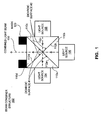
- FIG. 1 illustrates an apparatus for combining light of three different wavelengths from three physically separate light sources, according to an embodiment of the present invention
- FIG. 2 illustrates an apparatus for combining light of two different wavelengths from two physically separate light sources, according to an embodiment of the present invention
- FIG. 3 illustrates an apparatus for combining light of two different wavelengths from two physically separate light sources, according to another embodiment of the present invention
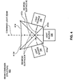
- FIG. 4 illustrates an apparatus for combining light of three different wavelengths from three physically separate light sources, according to still another embodiment of the present invention
- FIG. 5 illustrates an apparatus similar to the one shown in FIG. 1, but with the addition of combiner lenses between the light sources and prisms;
- FIG. 6 illustrates an apparatus for combining light of three different wavelengths from three physically separate light sources, according to a further embodiment of the present invention
- FIG. 7 illustrates how panels can be used in place of prisms
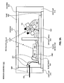
- FIG. 8A illustrates an implantable oximetry sensor, according to an embodiment of the present invention
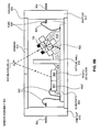
- FIG. 8B illustrates an implantable oximetry sensor, according to another embodiment of the present invention.
- FIG. 9 illustrates an implantable lead that includes the sensor of FIG. 8A, in accordance with an embodiment of the present invention
- FIG. 10 illustrates a rough cross-section of the lead shown in FIG. 9
- FIGS. 11A and 11B illustrate implantable self-calibrating sensors, according to embodiments of the present invention
- FIG. 12A illustrates an exemplary implantable stimulation device in electrical communication with a patient's heart by way of three leads, which are suitable for delivering multi-chamber stimulation and shock therapy;
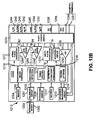
- FIG. 12B is a simplified block diagram of the multi-chamber implantable stimulation device of FIG. 12A.
- FIG. 1 shows a first embodiment of the present invention that combines light of three different wavelengths from three physically separate miniature light sources using dichroic surfaces.
- dichroic surfaces are likely dichroic mirrors, but can be dichroic filters, or combinations thereof.
- Dichroic surfaces have the property of reflecting light of specific wavelengths and passing light of other wavelengths.
- a beam combiner structure 102 in accordance with an embodiment of the present invention, includes three physically separate light sources 104, 106 and 108, each of which produces radiation of a different wavelength (e.g., 670, 700 and 805 nm).
- the light sources are preferably light emitting diodes (LEDs), but can be other less preferable sources such as, but not limited to, laser diodes and incandescent lamps.
- the light sources are shown as being mounted to a structure (a cube in this example) which is made up of four triangular prisms 110a, 110b, 110c and 110d that are bonded together, e.g., using an optical cement or some other clear epoxy resin.
- Appropriate sides of the prisms are coated to thereby form a pair of dichroic surfaces, labeled dichroic surface #1 and dichroic surface #2.
- dichroic surface #1 and dichroic surface #2 there are multiple ways this can be accomplished. However, it is believed that the most cost effective way is to have only one side of each prism 110a, 110b, 110c and 110d have a dichroic coating.
- side 112a of prism 110a and side 112c of prism 110c can be coated to form dichroic surface #1
- side 112b of prism 110b and side 112d of prism 110d can be coated to form dichroic surface #2.
- the prisms are likely made of glass, other suitable materials may be used, such as, but not limited to, plastics.
- the dichroic surface #1 will reflect the wavelength ( ⁇ 1 ) generated by the light source 104, and pass the wavelengths ( ⁇ 2 and ⁇ 3 ) generated by light sources 106 and 108.
- the dichroic surface #2 will reflect the wavelength ( ⁇ 3 ) generated by the light source 108, and pass the wavelengths ( ⁇ 1 and ⁇ 2 ) generated by light sources 104 and 106.
- the wavelength generated by light source 104 is 670nm
- the wavelength generated by light source 106 is 700nm
- the wavelength generated by light source 108 is 805nm (e.g., ⁇ 1 , ⁇ 2 and ⁇ 3 are, respectively, 670nm, 700nm and 805nm).
- the present invention can be implemented if dichroic surface #1 reflects light below 685nm and passes light above 685nm, and dichroic surface #2 reflects light above 750nm and passes light below 750 nm.
- the dichroic surface #1 and the dichroic surface #2 and the light sources 104 and 108 are positioned (including angled) relative to on another such that light transmitted by the light source 104 is reflected by the dichroic surface # 1 to travel in generally a same direction as light transmitted by the light source 108 that is reflected by the dichroic surface #2, as can be appreciated from the dashed lines shown.
- the light source 106 is positioned such that its light, which passes through the dichroic surfaces #1 and #2, travels in generally the same direction as the just mentioned reflected light, as can also be appreciated from the dashed lines shown.
- the light sources 104, 106 and 108 are serially energized, in a non-overlapping temporal relationship.
- the light of wavelengths ⁇ 1 , ⁇ 2 and ⁇ 3 are combined into a single combined beam 130 that is transmitted toward patient tissue that includes red blood cells.
- the light of different wavelengths ( ⁇ 1 , ⁇ 2 , and ⁇ 3 ) are combined into the single beam so that the light of each wavelength shines equally on nearby red blood cells, to thereby increase the likelihood that the computed oxygen saturation is accurate with varying blood flow rate, pH, hematocrit and hemoglobin.
- a mask 120 may be used to reduce internal reflections.
- the interleaved light stream is received by a light detector (discussed below in more detail with reference to FIG. 8), which preferably produces a separate signal for each of the wavelengths.
- a light detector discussed below in more detail with reference to FIG. 8
- time multiplexing is used to produce a signal path for each of the different wavelengths ( ⁇ 1 , ⁇ 2 and ⁇ 3 ) of received light.
- Each signal path will typically include one or more filters and an A/D converter to sample the received light signals.
- the received light signals can be analyzed so that oxygen saturation levels can be determined in any well known manner, or in any manner devised in the future.
- one of the light sources 104, 106 and 108 can be eliminated. If light source 106 is eliminated, then two dichroic surfaces are still needed, as can be appreciated from FIG. 3. However, if light source 104 (or light source 108) is eliminated, then only a single dichroic surface is necessary, as shown in FIG. 2.
- the single dichroic surface reflects the wavelength generated by the light source 104 and passes the wavelength generated by the light source 106. Since only one dichroic surface is used, the assembly of prisms can be simplified. More specifically, the structure (also a cube in this example) can be made up of only two triangular prisms 210a and 210b.
- FIGS. 1, 2 and 3 the overall structures, formed from multiple prisms, were shown as being cubic. While embodiments of the present invention encompass such cubic structures, they should not be limited thereto. For example, other shapes, such as the ones shown in FIGS. 4 and 6, can be used. As can be seen from FIG. 4, the prisms 410a, 410b, 410c and 410d that make up the structure form a shape that resembles a trapezoid. Also shown in FIG. 4 is that not all outer sides of the structure need be flat. More specifically, in this example, the outer side 414 of prism 410d, through which the combined light beam travels, is shown as being concave, to increase the exit angle. Also shown in FIG. 4 is that not all of the prisms need be of the same size and shape.
- combiner lenses 522 can added for reducing the emitted light angle before the light is combined by the dichroic surfaces.
- Such lenses 522 can be added in any of the embodiments described herein.
- FIG. 6 illustrates a variant of the present invention that has a simpler but likely somewhat larger overall size than the structure shown in FIG. 1.
- only three prisms 610a, 610b and 610c are used to form a three-dimensional rectangular structure.
- the beam combining structure 602 functions in a similar manner as the other structures discussed above. That is, dichroic surface #1 reflects the wavelength of light generated by the light source 104, and passes the wavelengths of light generated by the light sources 106 and 108.
- the dichroic surface #2 reflects the wavelength of light generated by the light source 108 and passes the wavelength of light generated by the light source 106. Because the light generated by the light source 104 is not incident upon the dichroic surface #2, it is not required that the dichroic surface #2 pass the wavelength generated by the light source 104, but it is allowed.
- the dichroic surfaces were described as being formed on sides of prisms.
- the use of such structures is beneficial because the prisms can be bonded together to form a sturdy structure to which the light sources can be securely attached, as shown in the FIGS.
- panels 714 are attached on at least one edge to a substrate 724, and dichroic surface(s) are formed on sides of the panels 714. While the panels 714 are likely made of glass, other suitable materials such as plastics may be used. (For FIG. 7, picture the substrate 724 being in the same plane as the page, and panels 714 extending perpendicularly out of the page.)
- the light sources 104, 106 and 108 are secured to the same substrate 724 to which the panels 714 are secured. As was discussed above with reference to FIGS.
- one of the light sources can be eliminated if two-wavelength pulse oximetry is to be used. Further, as was explained with reference to FIG. 2, if the light source to be eliminated is light source 104 or 108, then only one dichroic surface is required, which can be implemented using a single panel 714. In a similar manner as was described above with reference to FIGS. 4 and 6, the light sources and dichroic surfaces can be repositioned, so long as the arrangement results in the light of various wavelengths generally being combined into a single beam. Further, as was described with reference to FIG. 5, combiner lenses 522 can be added to the configuration shown in FIG. 7.
- critical angle reflectors could be used instead of dichroic surfaces to accomplish combining of light from the two or more separate light sources.
- the critical angle is the largest angle off a surface at which light will be totally reflected from the surface.
- Sides of prisms or panels can positioned relative to light sources such that light of two or more wavelengths, from two or more separate light sources, can be combined into a single beam in much that same way as was described above with the use of dichroic surfaces.
- the beam combiner assemblies discussed above can be built into a sensor assembly 802, such as those shown in FIGS. 8A and 8B.
- the sensor 802 in turn, can be built into an implantable lead 902, such as that shown in FIG. 9.
- the sensor assembly 802 includes a sensor enclosure or housing 804 within which are one of the beam combiner structures discussed above, a photo detector 806 and an optional application specific integrated circuit (ASIC) 807.
- the beam combiner 102 is shown.
- the housing 804 includes a tube 808 and a pair of end caps 810 and 812 that can be used to hermetically seal the components within the housing 802.
- the tube 808 can be made of an opaque material, such as metal (e.g., titanium or stainless steel) or ceramic, so long as it includes a window 814 that passes light of all the wavelengths of interest in the combined light beam (e.g., 130).
- the entire tube 808 can be made of a material that passes light of all the wavelengths of interest in the combined beam, and thus, in this embodiment the entire tube can be considered a window.
- the window 814 can for example be made of synthetic sapphire or some other appropriate material that passes light of all the wavelengths of interest.
- the entire tube 808 can be made from synthetic sapphire or some other appropriate material that passes light of all the wavelengths of interest. Exemplary synthetic sapphires are marketed by Imetra, Inc. (Elmsford, New York) and Swiss Jewel (Philadelphia, Pennsylvania).
- the beam combiner structure e.g., 102
- the window 814 and the photo detector 806 should be positioned such that the combined light beam produced by the beam combiner exits the housing 804 through the window 814 and such that the light backscattered from blood (outside the window) will be scattered back toward the photo detector 806.
- the optional ASIC 807 which can include filters, analog-to-digital circuitry, multiplexing circuitry, and the like, controls the light sources and processes the photo detector signals produced by the photo detector 806 in any manner well known in the art.
- the ASIC 807 preferably provides digital signals indicative of the photo detector signals to an implantable device, such as an implantable monitor, pacemaker, or ICD. If the ASIC 807 or equivalent circuitry is not included within the sensor, analog signals can be delivered between the sensor 802 and the implantable device. However, it is preferred that digital signals are sent to and from the sensor 802 because digital signals are less susceptible to noise and other degradation.
- An opaque optical wall 816 is positioned between the beam combiner structure 102 and the photo detector 806, so that light is not internally reflected from the beam combiner 102 to the photo detector 806.
- the beam combiner 102, optical wall 816, photo detector 806 and ASIC 807 can be attached to a substrate 820, e.g., by an epoxy 818.
- the substrate can be, e.g., a printed circuit board (PCB).
- Bond wires 822 can be used to attach the various components to the substrate 820, as well as to attach the substrate 820 to terminals 824 which extend through an insulated feedthrough 826 in the end cap 810.
- the housing 804, the feedthrough 826 and the endcaps 810 and 812 preferably provide hermeticity.
- the endcaps 810' and 812' are made of a conductive material, and the tube 808 is made of a nonconductive material (so that the endcaps are electrically isolated from one another).
- the feedthrough 826 shown in FIG. 8A because the terminals 824 can be connected directly to the conductive endcaps 810' and 812'. Nevertheless, a feedthrough may be used in the embodiment of FIG. 8B if desired.
- the sensor module 802 is built into an implantable lead 902. Accordingly, in this embodiment, the housing 804 of the sensor module 802 is sized to fit within the implantable lead 902. More specifically, the size of the beam combiner is preferably about 2 millimeters (mm) or less, and the size (shown as "d” in FIG. 10) of the sensor module 802 is about 4 mm or less, and preferably about 3 mm.
- the length of the sensor module 802, which extends axially in the lead 902 can be somewhat larger, because the length of the lead 902 is relatively large as compared to the diameter of the lead.
- the lead 902 may be transparent, or include its own window, opening, or the like.
- the lead 902 is shown as including tines 912 for attaching the lead in its desired position, but may include any other type of fixation means, or none at all.
- the lead 902 may also include a lumen 916 for a stylet, which can be used for guiding the lead to its desired position.
- wires 914 that provide power and possibly control signals to the sensor 802 from an implantable device, and provide pulse oxymetry signals from the sensor 802 to the implantable device.
- wire 914 there are only two wires 914, but there may be more. If the sensor 802 of FIG. 8B is used, then one wire 914 is attached to the terminal 824 that extends from the endcap 810', while another wire 914 is attached to the terminal 824 that extends from the other endcap 812'.
- the lead 902 can be, e.g., an implantable right atrial lead for implant in a patient's right atrial appendage, a right ventricular lead for transvenous insertion into the heart, a coronary sinus lead for placement in the coronary sinus region, or some other lead.
- the lead 902 can be implanted in or near a patient's heart, but this is not necessary.
- the exemplary lead 902 shown in FIG. 9 is a right ventricular lead that includes a ring electrode 908 and a tip electrode 910 that are connected to an implantable device by way of wires 904 and 906.
- the sensor can be within a catheter intended for placement in a blood vessel or other blood confining space.
- FIG. 10 is a rough cross-sectional view along the dashed line shown in FIG. 9, in accordance with an embodiment of the present invention the tube portion 808 of the sensor housing 804 is generally "D" shaped, so that it can be readily included with the implantable lead 902, while still allowing the lumen 916 (for a stylet) and wires 904 and 906 to fit within the same inner-space of the lead 902.
- Alternative shapes are also within the scope of the present invention. If the sensor 802 of FIG. 8B is used, then one of the wires 914 would also be seen in the cross-section of FIG. 10.
- the ASIC 807 controls the light sources the processes signals produced by the photo detector 806 in a manner well known in the art, it delivers signals indicative of the intensity of the detected light to an implantable device, an example of which is discussed below with reference to FIGS. 12A and 12B.
- the implantable device further processes the signal, e.g., for diagnostic and/or therapeutic use.
- the ASIC 807 has all electronics to provide a two-wire 914 digital interface to the implantable device, as shown in FIG. 9. Further, one of the two sensor wires 914 may be combined with one of the pacing electrode wires 904 or 906 so that only three total wires are needed.
- the lead 902 within which the sensor 802 is contained is attached to an implantable device. It is also possible that the sensor 802 is within a self contained hermetically sealed housing that communicates wirelessly with the implantable device.
- the implantable device can be, e.g., a monitor, pacemaker, or ICD.
- an exemplary implantable device 1210 that can be used to perform pacing, detect an arrhythmia, perform anti-arrhythmia therapy, detect specific cardiac events, etc., is described with reference to FIGS. 12A and 12B.
- the components are hermitically sealed within the sensor 802.
- the only elements running to and from the sensor 802 are wires 914 for providing power and possibly control signals to the sensor 802, and receiving pulse oxymetry signals from the sensor 802.
- the oxymetry sensor module 802 is located within the housing of an implantable device that includes a window through which light can be transmitted and received. In still another embodiment, the oxymetry sensor module 802 is in its own hermetically sealed housing that is attached directly to an implantable cardiac device. Additional details of how this can be accomplished are provided in commonly assigned U.S. Patent Application No. 10/913,942 , entitled "Autonomous Sensor Modules for Patient Monitoring”.
- the ASIC 807 controls the light sources and processes signals produced by the photo detector 806, as well as delivers signals indicative of the intensity of the detected light to an implantable device, an example of which is discussed below with reference to FIGS. 12A and 12B.
- the implantable device further processes the signal, e.g., for diagnostic and/or therapeutic use.
- the implantable device can include a microcontroller that determines levels of blood oxygen saturation and/or hematocrit based on the signals it receives from the photo detector 806.
- measures of oxygen saturation can be used, e.g., for pacing optimization, disease monitoring, and the like. Additionally or alternatively, the measures of oxygen saturation can be stored in memory for later transmission to an external device.
- the ASIC 807 can include filters, analog-to-digital circuitry, multiplexing circuitry, and the like, to control the light sources and process the photo detector signals produced by the photo detector 806.
- the ASIC 807 preferably provides digital signals indicative of the photo detector signals to an implantable device, such as an implantable monitor, pacemaker, or ICD. If the ASIC 807 or equivalent circuitry is not included within the sensor, analog signals can be delivered between the sensor 802 and the implantable device. However, it is preferred that digital signals are sent to and from the sensor 802 because digital signals are less susceptible to noise and other degradation.
- the sensor module 802 is located within the housing of an implantable device that includes a window through which light can be transmitted and received, or that the sensor module 802 is in its own hermetically sealed housing that is attached directly to an implantable cardiac device.
- Each light source (e.g., LED) transmits light in response to being driven by a drive signal, which is typically a current signal, but can be a voltage signal.
- a drive signal typically a current signal, but can be a voltage signal.
- the light sources age they become less efficient in that for a same drive signal they will transmit light of less intensity. If not compensated for, this will affect the intensity of the light detected by the photo detector 806, which will in turn adversely effect determinations of blood oxygen saturation, etc.
- a calibration photo detector 1106 is added, the output of which is used to compensate for aging or other changes to the light source(s), as will now be described with reference to FIG. 11A.
- FIG. 11A shows additional details of the ASIC 807, in accordance with specific embodiments of the present invention.
- the circuitry shown in FIG. 11A need not be implemented within the ASIC 807.
- the photo detector 806 that detects light scattered back into the housing 804 through the window 814 will often be referred to hereafter as the measurement photo detector 806, and the added photo detector 1106 that is used to compensate for changes in the light sources (e.g., due to aging) will be referred to as the calibration photo detector 1106.
- the measurement photo detector 806 the photo detector 806 that detects light scattered back into the housing 804 through the window 814
- the calibration photo detector 1106 the added photo detector 1106 that is used to compensate for changes in the light sources (e.g., due to aging)
- the beam combiner structure 102 will often be referred to simply as light source(s) 102, because the embodiments that relate to compensation can be used with a single light source, or with a device that does not necessarily use the specific beam combiners described above. Nevertheless, the embodiments described with reference to FIG. 11A would be very useful with the beam combiners described above.
- each light source transmits light having an intensity that is controlled by a corresponding drive signal 1112/1116.
- Such drive signal is controlled by a controller 1160, which likely outputs a digital drive control signal 1112 which is converted to an analog drive signal 1116 by a digital-to-analog converter (D/A) 1114.
- the controller 1160 in this embodiment, and other embodiments, can be a microcontroller, a processor, a state machine, random logic, or the like.
- the light output by the light source(s) is projected over a wide range of angles (e.g., from 120 degrees to 180 degrees). Accordingly, a portion of this light exits the housing 804 through the window 814, while other portions of the light are internally reflected.
- the opaque optical wall 816 is positioned between the light source(s) 102 and the measurement photo detector 806, to prevent the measurement photo detector 806 from detecting internally reflected light.
- the measurement photo detector 806 may detect a small amount of internally reflected light, which is allowed).
- the calibration photo detector 1106 is placed on the same side of the wall 816 as the light sources 102, and positioned relative to the window 814 such that the calibration photo detector 1106 detects internally reflected light from the light source(s) 102 without detecting light that is scattered back into the housing 804 through the window 814. (It is noted, that due to imperfections, the calibration photo detector 806 may detect a small amount of scattered light, which is allowed).
- the region of the window above the calibration photo detector 1106 can have a blocking or a reflecting coating such that the calibration photo detector 1106 generally only detects internally reflected light from the light source(s) 102. It is also possible that the calibration photo detector 1106 is arranged such that it detects light transmitted directly from the light source(s) 102, i.e., the light need not be internally reflected.
- the window 814 in FIG. 11A and the previously described FIGS. has been generally shown as a single portion through which light of interest can enter and exit the housing 804. However, it is noted that such window 814 can be made up of more than one distinct portion through which light of interest can enter and exit the housing 804.
- window 814 is intended to collectively encompass all portions of the housing through which light can enter and exit the housing, even if such portions are separated from one another (e.g., by opaque portions).
- the measurement photo detector 1106 detects light scattered back into the housing 804 through the window 814, and produces a measurement signal 1122 that is indicative of the intensity of the light detected by the measurement light detector 1106.
- the measurement signal 1112 is preferably filtered and amplified by an analog signal processing block 1124 (e.g., which includes a filter and amplifier), and digitized by an analog-to-digital (A/D) converter 1128, so that a digitized version 1130 of the signal is provided to the controller 1160.
- an analog signal processing block 1124 e.g., which includes a filter and amplifier
- A/D analog-to-digital
- the calibration light detector 1106 detects a portion of the light transmitted by the light source(s) that has not exited the housing 804 (e.g., the light is internally reflected and/or received directly from the light source(s)), and produces a calibration signal 1132 that is indicative of the intensity of such detected light.
- the calibration signal 1132 is preferably filtered and amplified by an analog signal processing block 1134 (e.g., which includes a filter and/or amplifier) and digitized by an analog-to-digital (A/D) converter 1140, so that a digitized version 1140 of the signal is provided to the controller 1160.
- an analog signal processing block 1134 e.g., which includes a filter and/or amplifier
- A/D analog-to-digital
- FIG. 11A a separate D/A converter 1114 and drive signal 1112 are shown for each light source.
- the controller can output a time multiplexed drive signal 1112 that is provided to a single D/A converter 1114, and a demultiplexer can be provided at the output of the D/A converter 1114.
- a demultiplexer will provide the analog version of the drive signal to the appropriate light source.
- the measurement photo detector 806 is shown as having its own analog signal processing block 1124 and A/D converter 1128, and the calibration photo detector 1106 has its own analog signal processing block 1134 and A/D converter 1138.
- a multiplexer is provided at the outputs of the detectors 806 and 1106 so that a single analog signal processing block and A/D converter can be used.
- a multiplexer can be provided between a single analog signal processing block and the detectors 806 and 1106.
- Such embodiments would reduce the circuitry, e.g., of the ASIC 807.
- the calibration signal 1132 or the filtered, amplified and digitized version thereof (i.e., 1140), is used to compensate for changes to the lights source(s) 102, e.g., due to aging, as will be described below.
- the controller 1160 adjusts the drive signal 1112, based on the intensity of the light detected by the calibration photo detector 1106, in order to keep the intensity of light transmitted by a light source substantially constant. More specifically, the controller 1160 adjusts the drive signal 1112, based on the calibration output signal 1132, or the filtered, amplified and digitized version thereof (i.e., 1140), to keep the intensity of the light transmitted by each light source substantially constant.
- the intensity of light transmitted by a light source is kept substantially constant by adjusting the drive signal 1112 in an effort to keep the portion of the calibration signal 1132 corresponding to that light source at a specified level.
- adjustments are made to the measurement signal 1122 to compensate for changes in the intensity of the light source(s) 102.
- the controller 1160 detects changes (likely reductions) in the intensity of the light source(s) 102 by detecting changes in the calibration signal 1132, or the filtered, amplified and digitized version thereof (i.e., 1140), in a similar manner as was discussed above. Then, based on the changes in the calibration output signal 1132, or the filtered, amplified and digitized version thereof (i.e., 1140), the controller 1160 adjusts the measurement signal 1122.
- a processor algorithmically compensates for changes to the intensity of the lights source(s) 102. More generally, a processor that uses the measurement signal 1122 (for a diagnostic and/or therapeutic purpose), detects changes in the intensity of the light transmitted by each light source based on the calibration signal, and the processor takes into account such changes in intensity when using the measurement signal for its diagnostic and/or therapeutic purpose. For example, if the controller detects a 5% reduction in the intensity of light of a specific wavelength (i.e., light from a specific light source) based on the calibration signal 1132, the processor can take such reduction into account when determining levels of blood oxygen saturation and/or levels of hematocrit.
- a specific wavelength i.e., light from a specific light source
- the processor can adjust where to look in the look-up table based on changes in the calibration signal.
- the processor uses an algorithm to determine levels of blood oxygen saturation, based on the intensity of detected scattered light, the processor can make adjustments to the algorithm based on changes in the calibration signal.
- hematocrit refers to the percentage of packed red blood cells in a volume of whole blood.
- Various techniques are known for determining hematocrit based on scattered light. For example, light of about 500 nm and light of about 800 nm can be directed at a blood sample, and an algorithm can be used to calculate hematocrit based on the intensities of detected scattered light.
- a pair of spatially separated photo detectors can be used to detect reflected infra red (IR) light, e.g., of 805 nm.
- the intensity of the IR light detected by the photo detector that is nearer to the IR light source is referred to as IRnear, and the intensity of the IR light detected by the photo detector farther from the IR light source is referred to as IRfar.
- IRnear The intensity of the IR light detected by the photo detector that is nearer to the IR light source
- IRfar the intensity of the IR light detected by the photo detector farther from the IR light source.
- a second measurement photo detector 806 (shown in dashed line) can be added, with the second measurement photo detector being further from (or closer to) the light source(s) 102 than the other measurement photo detector 806.
- This second measurement photo detector can have its own corresponding analog signal processing block and A/D converter, or such circuitry can be shared (e.g., multiplexed) with the other measurement photo detector.
- the above described embodiments of the present invention can be used to compensate for changes in the intensity of the IR light source, e.g., due to aging.
- the second measurement photo detector is placed within the housing 804 as shown in FIGS.
- such second measurement photo detector can be located farther from the optical wall 816 than the photo detector 806 shown, as can be appreciated from FIG. 11A.
- two light sources e.g., two 805 nm LEDs
- two 805 nm LEDs can be spatially separated and time multiplexed, with one light source being closer to the measurement photo detector 806 than the other.
- FIG. 11 B shows an exemplary layout of elements that can be inserted into a sealed tube 808 (not shown in FIG. 11 B), as described above in the discussion of FIG. 8A.
- Using a pair of spatially separated 805nm light sources is advantageous, as compared to using a pair of spatially separated measurement light detectors, because light sources (such as LEDs) are typically significantly smaller than photo detectors, thus resulting in space savings.
- the calibration photo detector 806 will detect internally reflected light from the near and far light sources 202, and the measurement photo detector 806 will detect scattered light from the near and far light sources 202.
- the exemplary implantable stimulation device 1210 is shown as being in electrical communication with a patient's heart 1212 by way of three leads, 1220, 1224 and 1230, suitable for delivering multi-chamber stimulation and shock therapy.
- the sensor module 802 of the present invention can be placed within any of these leads, as was described above.
- a further dedicated lead or catheter can be provided for the purpose of containing the sensor 802 and placing the sensor 802 at a desired measurement site.
- the stimulation device 1210 is coupled to an implantable right atrial lead 1220 having at least an atrial tip electrode 1222, which typically is implanted in the patient's right atrial appendage.
- the stimulation device 1210 is coupled to a "coronary sinus" lead 1224 designed for placement in the "coronary sinus region" via the coronary sinus for positioning a distal electrode adjacent to the left ventricle and/or additional electrode(s) adjacent to the left atrium.
- coronary sinus region refers to the vasculature of the left ventricle, including any portion of the coronary sinus, great cardiac vein, left marginal vein, left posterior ventricular vein, middle cardiac vein, and/or small cardiac vein or any other cardiac vein accessible by the coronary sinus.
- the exemplary coronary sinus lead 1224 is designed to receive atrial and ventricular cardiac signals and to deliver left ventricular pacing therapy using at least a left ventricular tip electrode 1226, left atrial pacing therapy using at least a left atrial ring electrode 1227, and shocking therapy using at least a left atrial coil electrode 1228.
- the stimulation device 1210 is also shown in electrical communication with the patient's heart 1212 by way of an implantable right ventricular lead 1230 having, in this embodiment, a right ventricular tip electrode 1232, a right ventricular ring electrode 1234, a right ventricular (RV) coil electrode 1236, and an SVC coil electrode 1238.
- the right ventricular lead 1230 is transvenously inserted into the heart 1212 so as to place the right ventricular tip electrode 1232 in the right ventricular apex so that the RV coil electrode 1236 will be positioned in the right ventricle and the SVC coil electrode 1238 will be positioned in the superior vena cava.
- the right ventricular lead 1230 is capable of receiving cardiac signals and delivering stimulation in the form of pacing and shock therapy to the right ventricle.
- FIG. 12B a simplified block diagram is shown of the multi-chamber implantable stimulation device 1210, which is capable of treating both fast and slow arrhythmias with stimulation therapy, including cardioversion, defibrillation, and pacing stimulation. While a particular multi-chamber device is shown, this is for illustration purposes only, and one of skill in the art could readily duplicate, eliminate or disable the appropriate circuitry in any desired combination to provide a device capable of treating the appropriate chamber(s) with cardioversion, defibrillation and pacing stimulation.
- the housing 1240 for the stimulation device 1210 is often referred to as the "can", “case” or “case electrode” and may be programmably selected to act as the return electrode for all "unipolar" modes.
- the housing 1240 may further be used as a return electrode alone or in combination with one or more of the coil electrodes, 1228, 1236 and 1238, for shocking purposes.
- the housing 1240 further includes a connector (not shown) having a plurality of terminals, 1242, 1244, 1246, 1248, 1252, 1254, 1256, and 1258 (shown schematically and, for convenience, the names of the electrodes to which they are connected are shown next to the terminals).
- the connector includes at least a right atrial tip terminal (AR TIP) 1242 adapted for connection to the atrial tip electrode 1222.
- AR TIP right atrial tip terminal
- the connector includes at least a left ventricular tip terminal (VL TIP) 1244, a left atrial ring terminal (AL RING) 1246, and a left atrial shocking terminal (AL COIL) 1248, which are adapted for connection to the left ventricular tip electrode 1226, the left atrial ring electrode 1227, and the left atrial coil electrode 1228, respectively.
- VL TIP left ventricular tip terminal
- a RING left atrial ring terminal
- AL COIL left atrial shocking terminal
- the connector further includes a right ventricular tip terminal (VR TIP) 1252, a right ventricular ring terminal (VR RING) 1254, a right ventricular shocking terminal (RV COIL) 1256, and an SVC shocking terminal (SVC COIL) 1258, which are adapted for connection to the right ventricular tip electrode 1232, right ventricular ring electrode 1234, the RV coil electrode 1236, and the SVC coil electrode 1238, respectively.
- VR TIP right ventricular tip terminal
- VR RING right ventricular ring terminal
- RV COIL right ventricular shocking terminal
- SVC COIL SVC shocking terminal
- the connector is also shown as including terminals 1259 and 1261 (OXYMETRY TERMINALS), which are configured for connection to the wires 914 that are connected to the sensor module 802, to support the delivery of control signals to the sensor module 802, and to collect oxymetry data from the sensor module 802.
- terminals 1259 and 1261 OXYMETRY TERMINALS
- a programmable microcontroller 1260 which controls the various modes of stimulation therapy, including pacing optimization and anti-arrhythmia therapy.
- the microcontroller 1260 can also determine measures of blood oxygen saturation and/or hematocrit based on the signals it receives from an oximetry sensor of the present invention. Such measures of oxygen saturation and/or hematocrit can be used, e.g., for pacing optimization, disease monitoring, and the like. Additionally or alternatively, the measures of oxygen saturation and/or hematocrit can be stored in memory 1294 for later transmission to an external device 1202 using the telemetry circuit 1201.
- the oxymetry sensor module 802 provides analog signals to the implantable device, then the terminals 1259 and 1261, through switch 1274, can provide such signals to an analog-to-digital (A/D) converter 1290 that converts the signals to a digital format understood by the microcontroller 1260. It is also possible that a dedicated A/D converter be provided within the implantable device 1210 for the purpose of digitizing signals received from the oximetry sensor. If the oxymetry sensor 802 provides digital signals to the implantable device 1210, then such signals may be provided directly to the microcontroller 1210, assuming it is the microcontroller 1260 that performs the processing that determines measures of blood oxygen saturation and/or hematocrit based on the signals. It is also possible that the implantable device 1210 include circuitry, external to the microcontroller 1260, which is dedicated to determining measures of blood oxygen saturation and/or hematocrit.
- the microcontroller 1260 typically includes a microprocessor, or equivalent control circuitry, designed specifically for controlling the delivery of stimulation therapy and can further include RAM or ROM memory, logic and timing circuitry, state machine circuitry, and I/O circuitry.
- the microcontroller 1260 includes the ability to analyze signals (data) as controlled by a program code stored in a designated block of memory.
- the details of the design of the microcontroller 1260 are not critical to the present invention. Rather, any suitable microcontroller 1260 can be used to carry out the functions described herein.
- the use of microprocessor-based control circuits for performing timing, control and data analysis functions are well known in the art.
- U.S. Pat. No. 4,788,980 Mann et. al.
- an atrial pulse generator 1270 and a ventricular pulse generator 1272 generate pacing stimulation pulses for delivery by the right atrial lead 1220, the right ventricular lead 1230, and/or the coronary sinus lead 1224 via an electrode configuration switch 1274.
- the atrial and ventricular pulse generators, 1270 and 1272 may include dedicated, independent pulse generators, multiplexed pulse generators, or shared pulse generators.
- the pulse generators, 1270 and 1272 are controlled by the microcontroller 1260 via appropriate control signals, 1276 and 1278, respectively, to trigger or inhibit the stimulation pulses.
- the microcontroller 1260 further includes timing control circuitry 1279 which is used to control pacing parameters (e.g., the timing of stimulation pulses) as well as to keep track of the timing of refractory periods, PVARP intervals, noise detection windows, evoked response windows, alert intervals, marker channel timing, etc., which is well known in the art.
- pacing parameters include, but are not limited to, atrio-ventricular delay, interventricular delay and interatrial delay.
- the switch bank 1274 includes a plurality of switches for connecting the desired electrodes to the appropriate I/O circuits, thereby providing complete electrode programmability. Accordingly, the switch 1274, in response to a control signal 1280 from the microcontroller 1260, determines the polarity of the stimulation pulses (e.g., unipolar, bipolar, combipolar, etc.) by selectively closing the appropriate combination of switches (not shown) as is known in the art.
- the switch 1274 can also be used to connect wires from an oximetry sensor 802 to appropriate I/O circuits.
- Atrial sensing circuits 1282 and ventricular sensing circuits 1284 may also be selectively coupled to the right atrial lead 1220, coronary sinus lead 1224, and the right ventricular lead 1230, through the switch 1274 for detecting the presence of cardiac activity in each of the four chambers of the heart.
- the atrial (ATR. SENSE) and ventricular (VTR. SENSE) sensing circuits, 1282 and 1284 may include dedicated sense amplifiers, multiplexed amplifiers, or shared amplifiers.
- the switch 1274 determines the "sensing polarity" of the cardiac signal by selectively closing the appropriate switches, as is also known in the art. In this way, the clinician may program the sensing polarity independent of the stimulation polarity.
- Each sensing circuit, 1282 and 1284 preferably employs one or more low power, precision amplifiers with programmable gain and/or automatic gain control, bandpass filtering, and a threshold detection circuit, as known in the art, to selectively sense the cardiac signal of interest.
- the automatic gain control enables the device 1210 to deal effectively with the difficult problem of sensing the low amplitude signal characteristics of atrial or ventricular signals.
- the outputs of the atrial and ventricular sensing circuits, 1282 and 1284 are connected to the microcontroller 1260 which, in turn, are able to trigger or inhibit the atrial and ventricular pulse generators, 1270 and 1272, respectively, in a demand fashion in response to the absence or presence of cardiac activity, in the appropriate chambers of the heart.
- the sensing circuits, 1282 and 1284 receive control signals over signal lines, 1286 and 1288, from the microcontroller 1260 for purposes of measuring cardiac performance at appropriate times, and for controlling the gain, threshold, polarization charge removal circuitry (not shown), and timing of any blocking circuitry (not shown) coupled to the inputs of the sensing circuits, 1282 and 1286.
- the device 1210 utilizes the atrial and ventricular sensing circuits, 1282 and 1284, to sense cardiac signals to determine whether a rhythm is physiologic or pathologic.
- the timing intervals between sensed events e.g., P-waves, R-waves, and depolarization signals associated with fibrillation which are sometimes referred to as "F-waves" or "Fib-waves"
- F-waves fibrillation which are sometimes referred to as "F-waves” or "Fib-waves
- F-waves fibrillation which are sometimes referred to as "F-waves" or "Fib-waves”
- a predefined rate zone limit i.e., bradycardia, normal, low rate VT, high rate VT, and fibrillation rate zones
- various other characteristics e.g., sudden onset, stability, physiologic sensors, and morphology, etc.
- Cardiac signals are also applied to the inputs of an analog-to-digital (A/D) data acquisition system 1290.
- the data acquisition system 1290 is configured to acquire intracardiac electrogram signals, convert the raw analog data into a digital signal, and store the digital signals for later processing and/or telemetric transmission to an external device 1202.
- the data acquisition system 1290 is coupled to the right atrial lead 1220, the coronary sinus lead 1224, and the right ventricular lead 1230 through the switch 1274 to sample cardiac signals across any pair of desired electrodes.
- the data acquisition system 1290 can be coupled to the microcontroller 1260, or other detection circuitry, for detecting an evoked response from the heart 1212 in response to an applied stimulus, thereby aiding in the detection of "capture". Capture occurs when an electrical stimulus applied to the heart is of sufficient energy to depolarize the cardiac tissue, thereby causing the heart muscle to contract.
- the microcontroller 1260 detects a depolarization signal during a window following a stimulation pulse, the presence of which indicates that capture has occurred.
- the microcontroller 1260 enables capture detection by triggering the ventricular pulse generator 1272 to generate a stimulation pulse, starting a capture detection window using the timing control circuitry 1279 within the microcontroller 1260, and enabling the data acquisition system 1290 via control signal 1292 to sample the cardiac signal that falls in the capture detection window and, based on the amplitude, determines if capture has occurred.
- capture detection circuitry and algorithms are well known. See for example, U.S. Pat. No. 4,729,376 (Decote, Jr. ); U.S. Pat. No. 4,708,142 (Decote, Jr. ); U.S. Pat. No. 4,686,988 (Sholder ); U.S. Pat. No. 4,969,467 (Callaghan et. al. ); and U.S. Pat. No. 5,350,410 (Kleks et. al. ).
- the type of capture detection system used is not critical to the present invention.
- the microcontroller 1260 is further coupled to a memory 1294 by a suitable data/address bus 1296, wherein the programmable operating parameters used by the microcontroller 1260 are stored and modified, as required, in order to customize the operation of the stimulation device 1210 to suit the needs of a particular patient.
- Such operating parameters define, for example, pacing pulse amplitude, pulse duration, electrode polarity, rate, sensitivity, automatic features, arrhythmia detection criteria, and the amplitude, waveshape and vector of each shocking pulse to be delivered to the patient's heart 1212 within each respective tier of therapy.
- Data acquired by the data acquisition system 1290 can be used for subsequent analysis to guide the programming of the device and/or to monitor oxygen saturation and/or hematocrit, appropriately adjust pacing interval parameters, select optimum pacing intervals, and/or select appropriate anti-arrhythmia therapy.
- the operating parameters of the implantable device 1210 may be non-invasively programmed into the memory 1294 through a telemetry circuit 1201 in telemetric communication with the external device 1202, such as a programmer, transtelephonic transceiver, or a diagnostic system analyzer.
- the telemetry circuit 1201 is activated by the microcontroller by a control signal 1206.
- the telemetry circuit 1201 advantageously allows intracardiac electrograms, oxygen saturation information, hematocrit information and status information relating to the operation of the device 1210 (as contained in the microcontroller 1260 or memory 1294) to be sent to an external device 1202 through an established communication link 1204.
- the stimulation device 1210 can further include one or more physiologic sensors 1208, which can be located within the stimulation device housing 1240 as shown, or can be located external to the housing.
- the stimulation device 1210 additionally includes a battery 1212 which provides operating power to all of the circuits shown in FIG. 12B.
- the battery 1212 For the stimulation device 1210, which employs shocking therapy, the battery 1212 must be capable of operating at low current drains for long periods of time, and then be capable of providing high-current pulses (for capacitor charging) when the patient requires a shock pulse.
- the battery 1212 should also have a predictable discharge characteristic so that elective replacement time can be detected. Accordingly, the device 1210 preferably employs lithium/silver vanadium oxide batteries, but is not limited thereto.
- the stimulation device 1210 can further include a magnet detection circuitry (not shown), coupled to the microcontroller 1260. It is the purpose of the magnet detection circuitry to detect when a magnet is placed over the stimulation device 1210, which magnet may be used by a clinician to perform various test functions of the stimulation device 1210 and/or to signal the microcontroller 1260 that the external programmer 1202 is in place to receive or transmit data to the microcontroller 1260 through the telemetry circuits 1201.
- a magnet detection circuitry to detect when a magnet is placed over the stimulation device 1210, which magnet may be used by a clinician to perform various test functions of the stimulation device 1210 and/or to signal the microcontroller 1260 that the external programmer 1202 is in place to receive or transmit data to the microcontroller 1260 through the telemetry circuits 1201.
- the device 1210 is shown as having an impedance measuring circuit 1213 which is enabled by the microcontroller 1260 via a control signal 1214.
- the known uses for an impedance measuring circuit 1213 include, but are not limited to, lead impedance surveillance during the acute and chronic phases for proper lead positioning or dislodgement; detecting operable electrodes and automatically switching to an operable pair if dislodgement occurs; measuring respiration or minute ventilation; measuring thoracic impedance for determining shock thresholds; measuring thoracic impedance for detecting and assessing the severity of pulmonary edema; detecting when the device has been implanted; measuring stroke volume; and detecting the opening of heart valves, etc.
- the impedance measuring circuit 1213 is advantageously coupled to the switch 1274 so that any desired electrode may be used.
- extra electrodes can be added to the device housing, thereby limiting the test electric field to the peripheral tissue.
- the stimulation device 1210 In the case where the stimulation device 1210 is also intended to operate as an implantable cardioverter/defibrillator (ICD) device, it must detect the occurrence of an arrhythmia, and automatically apply an appropriate electrical shock therapy to the heart aimed at terminating the detected arrhythmia. To this end, the microcontroller 1260 further controls a shocking circuit 1216 by way of a control signal 1218.
- the shocking circuit 1216 generates shocking pulses of low (up to 0.5 Joules), moderate (0.5-10 Joules), or high energy (12 to 40 Joules), as controlled by the microcontroller 1260.
- Such shocking pulses are applied to the patient's heart 1212 through at least two shocking electrodes, and as shown in this embodiment, selected from the left atrial coil electrode 1228, the RV coil electrode 1236, and/or the SVC coil electrode 1238.
- the housing 1240 may act as an active electrode in combination with the RV electrode 1236, or as part of a split electrical vector using the SVC coil electrode 1238 or the left atrial coil electrode 1228 (i.e., using the RV electrode as a common electrode).
- Cardioversion shocks are generally considered to be of low to moderate energy level (so as to minimize pain felt by the patient), and/or synchronized with an R-wave and/or pertaining to the treatment of tachycardia.
- Defibrillation shocks are generally of moderate to high energy level (i.e., corresponding to thresholds in the range of 5-40 Joules), delivered asynchronously (since R-waves may be too disorganized to be recognize), and pertaining exclusively to the treatment of ventricular fibrillation.
- the microcontroller 1260 is capable of controlling the synchronous or asynchronous delivery of the shocking pulses.
- anti-tachycardia pacing in which low-voltage pacing pulses are applied to pace-terminate the arrhythmia. This approach is particularly effective in low rate ventricular tachycardias.
Abstract
Description
- Embodiments of the present invention relate to implantable self-calibrating optical sensors that are used, e.g., for obtaining measures of blood oxygen saturation and/or hematocrit.
- Blood oxygen saturation is the relative amount of oxygenated hemoglobin in all of the hemoglobin present in the blood stream. This hemoglobin is packaged in biconcave discs of approximately 10 micrometers diameter which commonly occur with a density of approximately five million red blood cells per cubic millimeter. When radiant energy (e.g., light) is incident upon red blood cells, the red blood cells both scatter and transmit the incident radiant energy. The differential absorption by oxygenated and non-oxygenated hemoglobin of the radiant energy reflected by and transmitted through the red blood cells furnishes the basis for the oxygen saturation measurements.
- More specifically, pulse oximeters use light of two or more different centered wavelengths (e.g., produced by two or more light sources) to obtain measures of blood oxygen saturation by measuring the absorption and/or scattering of oxyhemoglobin and reduced hemoglobin. The measured scattering data allows for the calculation of the relative concentrations of reduced hemoglobin and oxyhemoglobin, and therefore blood oxygen saturation levels, since the scattering relationships are known.
- Most multi-wavelength pulse oximeters are non-implantable devices that are clipped onto a patient's finger or ear lobe. However, it is believed that it would be beneficial to chronically implant pulse oximeters so that measures of oxygen saturation and hematocrit (the density of red blood cells) can be used as feedback for pacing optimization, disease monitoring, and the like.
- Some multi-wavelength implantable oximeter catheters are known, as can be appreciated from
U.S. Patent Nos. 3,847,483 and4,114,604 . For multi-wavelength oximeters to work properly, light from two or more light sources (e.g., from 670, 700 and 805 nm wavelength LEDs) should be combined into a single beam, to assure that the computed oxygen saturation is accurate with varying blood flow rate, pH, hematocrit and hemoglobin. In the devices of the '483 and '604 patents, fiber optic guides are used to combine the light of multiple wavelengths into the single beam. This, however, requires significant physical space. Thus, in the devices of the '482 and '604 patents, the light sources and fiber optic guides are located in a housing that is a distance from the measurement site, and optical fibers that are within a catheter are used to deliver the combined light beam to the measurement site at the distal end of the catheter. - It would be beneficial if an implantable optical combiner requiring less physical space can be provided, thereby enabling the optical combiner to be located at the measurement site.
- The light sources that are used to produce the light useful for obtaining measures of blood oxygen saturation, etc., may produce light of less intensity, as such light sources age. If not compensated for, this will affect the intensity of the scattered light detected by a photo detector, which will in turn adversely effect determinations of blood oxygen saturation, etc. Accordingly, there is also a need to compensate for changes in the intensity of the light produced by such light sources.
- Embodiments of the present invention are directed to implantable systems, and methods for use therewith, that compensate for changes in the intensity of light transmitted by one or more light sources of the implantable systems. Such changes in intensity can be due, e.g., to aging of the light sources. The light sources can be, e.g., light emitting diodes (LEDs), but are not limited thereto.
- In accordance with specific embodiments of the present invention, the implantable system includes an implantable housing including a window through which light can pass. The term window, as used herein, is intended to collectively encompass all portions of the housing through which light of interest can enter and exit the housing, even if such portions are separated from one another (e.g., by opaque portions). Included within the housing is at least one light source, a measurement light detector and a calibration light detector. Each light source transmits light of a corresponding wavelength. The intensity of the light transmitted by each light source is controlled by a corresponding drive signal that drives the light source. A portion of the light of each wavelength exits the housing through the window. The measurement light detector detects light of each wavelength scattered back into the housing through the window, and produces a measurement signal that is indicative of the intensity of the light of each wavelength detected by the measurement light detector. The calibration light detector detects a portion of the light of each wavelength that has not exited the housing, to produce a calibration signal that is indicative of the intensity of the light of the wavelength detected by the calibration light detector, which is indicative of the intensity of the light transmitted by each light source.
- In accordance with specific embodiments, a controller adjusts each drive signal, based on the calibration signal, to keep the intensity of the light transmitted by each light source substantially constant. In accordance with other embodiments of the present invention, a controller adjusts the measurement signal, based on the calibration signal, to compensate for changes in the intensity of the light transmitted by each light source. In still other embodiments, rather than adjusting signals, a processor (that uses the measurement signal for a diagnostic and/or therapeutic purpose) detects changes in the intensity of the light transmitted by each light source based on the calibration signal, and takes into account the changes in intensity when using the measurement signal for a diagnostic and/or therapeutic purpose. For example, the processor can take such changes in intensity into account by making appropriate adjustments to algorithms that are used to determine levels of blood oxygen saturation and/or levels hematocrit based on the measurement signal.
- This invention may be carried into practice in various ways and some embodiments will now be described by way of example with reference to the accompanying drawings, in which:
- FIG. 1 illustrates an apparatus for combining light of three different wavelengths from three physically separate light sources, according to an embodiment of the present invention;
- FIG. 2 illustrates an apparatus for combining light of two different wavelengths from two physically separate light sources, according to an embodiment of the present invention;
- FIG. 3 illustrates an apparatus for combining light of two different wavelengths from two physically separate light sources, according to another embodiment of the present invention;
- FIG. 4 illustrates an apparatus for combining light of three different wavelengths from three physically separate light sources, according to still another embodiment of the present invention;
- FIG. 5 illustrates an apparatus similar to the one shown in FIG. 1, but with the addition of combiner lenses between the light sources and prisms;
- FIG. 6 illustrates an apparatus for combining light of three different wavelengths from three physically separate light sources, according to a further embodiment of the present invention;
- FIG. 7 illustrates how panels can be used in place of prisms;
- FIG. 8A illustrates an implantable oximetry sensor, according to an embodiment of the present invention;
- FIG. 8B illustrates an implantable oximetry sensor, according to another embodiment of the present invention;
- FIG. 9 illustrates an implantable lead that includes the sensor of FIG. 8A, in accordance with an embodiment of the present invention;
- FIG. 10 illustrates a rough cross-section of the lead shown in FIG. 9;
- FIGS. 11A and 11B illustrate implantable self-calibrating sensors, according to embodiments of the present invention;
- FIG. 12A illustrates an exemplary implantable stimulation device in electrical communication with a patient's heart by way of three leads, which are suitable for delivering multi-chamber stimulation and shock therapy; and
- FIG. 12B is a simplified block diagram of the multi-chamber implantable stimulation device of FIG. 12A.
- In the description of the invention that follows, the left-most digit(s) of a reference number identifies the drawing in which the reference number first appears.
- FIG. 1 shows a first embodiment of the present invention that combines light of three different wavelengths from three physically separate miniature light sources using dichroic surfaces. Such dichroic surfaces are likely dichroic mirrors, but can be dichroic filters, or combinations thereof. Dichroic surfaces have the property of reflecting light of specific wavelengths and passing light of other wavelengths.
- Referring to FIG. 1, a beam combiner
structure 102, in accordance with an embodiment of the present invention, includes three physicallyseparate light sources triangular prisms dichroic surface # 1 anddichroic surface # 2. There are multiple ways this can be accomplished. However, it is believed that the most cost effective way is to have only one side of eachprism side 112a ofprism 110a andside 112c ofprism 110c can be coated to formdichroic surface # 1, andside 112b ofprism 110b andside 112d ofprism 110d can be coated to formdichroic surface # 2. While the prisms are likely made of glass, other suitable materials may be used, such as, but not limited to, plastics. - In accordance with an embodiment of the present invention, the
dichroic surface # 1 will reflect the wavelength (λ1) generated by thelight source 104, and pass the wavelengths (λ2 and λ3) generated bylight sources dichroic surface # 2 will reflect the wavelength (λ3) generated by thelight source 108, and pass the wavelengths (λ1 and λ2) generated bylight sources light source 104 is 670nm, the wavelength generated bylight source 106 is 700nm, and the wavelength generated bylight source 108 is 805nm (e.g., λ1, λ2 and λ3 are, respectively, 670nm, 700nm and 805nm). Continuing with this example, the present invention can be implemented ifdichroic surface # 1 reflects light below 685nm and passes light above 685nm, anddichroic surface # 2 reflects light above 750nm and passes light below 750 nm. - Still referring to FIG. 1, the
dichroic surface # 1 and thedichroic surface # 2 and thelight sources light source 104 is reflected by thedichroic surface # 1 to travel in generally a same direction as light transmitted by thelight source 108 that is reflected by thedichroic surface # 2, as can be appreciated from the dashed lines shown. Additionally, thelight source 106 is positioned such that its light, which passes through thedichroic surfaces # 1 and #2, travels in generally the same direction as the just mentioned reflected light, as can also be appreciated from the dashed lines shown. - In practice, the
light sources beam 130 that is transmitted toward patient tissue that includes red blood cells. The light of different wavelengths (λ1, λ2, and λ3) are combined into the single beam so that the light of each wavelength shines equally on nearby red blood cells, to thereby increase the likelihood that the computed oxygen saturation is accurate with varying blood flow rate, pH, hematocrit and hemoglobin. Amask 120 may be used to reduce internal reflections. - When transmitted toward patient tissue, some of the light energy is scattered by blood. The different wavelengths are differently scattered, depending on the oxygen saturation level of the blood. After being scattered by blood, the interleaved light stream is received by a light detector (discussed below in more detail with reference to FIG. 8), which preferably produces a separate signal for each of the wavelengths. At a high level, time multiplexing is used to produce a signal path for each of the different wavelengths (λ1, λ2 and λ3) of received light. Each signal path will typically include one or more filters and an A/D converter to sample the received light signals. Using electronic circuitry, firmware and/or software, the received light signals can be analyzed so that oxygen saturation levels can be determined in any well known manner, or in any manner devised in the future.
- While three-wavelength pulse oximetry provides more accuracy than two-wavelength pulse oximetry, the accuracy obtained using two-wavelength pulse oximetry is satisfactory for many applications. Accordingly, in accordance with embodiments of the present invention, one of the
light sources light source 106 is eliminated, then two dichroic surfaces are still needed, as can be appreciated from FIG. 3. However, if light source 104 (or light source 108) is eliminated, then only a single dichroic surface is necessary, as shown in FIG. 2. - Referring to FIG. 2, the single dichroic surface reflects the wavelength generated by the
light source 104 and passes the wavelength generated by thelight source 106. Since only one dichroic surface is used, the assembly of prisms can be simplified. More specifically, the structure (also a cube in this example) can be made up of only twotriangular prisms - In FIGS. 1, 2 and 3, the overall structures, formed from multiple prisms, were shown as being cubic. While embodiments of the present invention encompass such cubic structures, they should not be limited thereto. For example, other shapes, such as the ones shown in FIGS. 4 and 6, can be used. As can be seen from FIG. 4, the
prisms outer side 414 ofprism 410d, through which the combined light beam travels, is shown as being concave, to increase the exit angle. Also shown in FIG. 4 is that not all of the prisms need be of the same size and shape. - Referring now to FIG. 5, in accordance with an embodiment of the present invention,
combiner lenses 522 can added for reducing the emitted light angle before the light is combined by the dichroic surfaces.Such lenses 522 can be added in any of the embodiments described herein. - FIG. 6 illustrates a variant of the present invention that has a simpler but likely somewhat larger overall size than the structure shown in FIG. 1. In this embodiment, only three
prisms beam combining structure 602 functions in a similar manner as the other structures discussed above. That is,dichroic surface # 1 reflects the wavelength of light generated by thelight source 104, and passes the wavelengths of light generated by thelight sources dichroic surface # 2 reflects the wavelength of light generated by thelight source 108 and passes the wavelength of light generated by thelight source 106. Because the light generated by thelight source 104 is not incident upon thedichroic surface # 2, it is not required that thedichroic surface # 2 pass the wavelength generated by thelight source 104, but it is allowed. - In the above discussed FIGS. 1 through 6, the dichroic surfaces were described as being formed on sides of prisms. The use of such structures is beneficial because the prisms can be bonded together to form a sturdy structure to which the light sources can be securely attached, as shown in the FIGS. However, in alternative embodiments, explained below with reference 7, this need not be the case.
- Referring to FIG. 7, rather than using prisms,
panels 714 are attached on at least one edge to asubstrate 724, and dichroic surface(s) are formed on sides of thepanels 714. While thepanels 714 are likely made of glass, other suitable materials such as plastics may be used. (For FIG. 7, picture thesubstrate 724 being in the same plane as the page, andpanels 714 extending perpendicularly out of the page.) In this embodiment, rather than securing thelight sources light sources same substrate 724 to which thepanels 714 are secured. As was discussed above with reference to FIGS. 2 and 3, one of the light sources can be eliminated if two-wavelength pulse oximetry is to be used. Further, as was explained with reference to FIG. 2, if the light source to be eliminated islight source single panel 714. In a similar manner as was described above with reference to FIGS. 4 and 6, the light sources and dichroic surfaces can be repositioned, so long as the arrangement results in the light of various wavelengths generally being combined into a single beam. Further, as was described with reference to FIG. 5,combiner lenses 522 can be added to the configuration shown in FIG. 7. - While the above described embodiments included either two or three separate light sources, one of ordinary skill in the art would understand, based on the above description, that light from more than three light sources can be combined in a similar manner. Accordingly, it is within the spirit and scope of the present invention that more than three light sources and more than two dichroic surfaces can be used. Such embodiments can be used for multi-wavelength oximetry that uses more than three wavelengths.
- In accordance with other embodiments of the present invention, critical angle reflectors could be used instead of dichroic surfaces to accomplish combining of light from the two or more separate light sources. The critical angle is the largest angle off a surface at which light will be totally reflected from the surface. Sides of prisms or panels can positioned relative to light sources such that light of two or more wavelengths, from two or more separate light sources, can be combined into a single beam in much that same way as was described above with the use of dichroic surfaces.
- In accordance with embodiments of the present invention, the beam combiner assemblies discussed above can be built into a
sensor assembly 802, such as those shown in FIGS. 8A and 8B. Thesensor 802, in turn, can be built into animplantable lead 902, such as that shown in FIG. 9. - Referring to FIG. 8A, in accordance with an embodiment of the present invention the
sensor assembly 802 includes a sensor enclosure orhousing 804 within which are one of the beam combiner structures discussed above, aphoto detector 806 and an optional application specific integrated circuit (ASIC) 807. In FIG. 8A, thebeam combiner 102 is shown. However, any of theother beam combiners housing 804 includes atube 808 and a pair ofend caps housing 802. Thetube 808 can be made of an opaque material, such as metal (e.g., titanium or stainless steel) or ceramic, so long as it includes awindow 814 that passes light of all the wavelengths of interest in the combined light beam (e.g., 130). In an alternative embodiment, theentire tube 808 can be made of a material that passes light of all the wavelengths of interest in the combined beam, and thus, in this embodiment the entire tube can be considered a window. Thewindow 814 can for example be made of synthetic sapphire or some other appropriate material that passes light of all the wavelengths of interest. Alternatively, theentire tube 808 can be made from synthetic sapphire or some other appropriate material that passes light of all the wavelengths of interest. Exemplary synthetic sapphires are marketed by Imetra, Inc. (Elmsford, New York) and Swiss Jewel (Philadelphia, Pennsylvania). - The beam combiner structure (e.g., 102), the
window 814 and thephoto detector 806 should be positioned such that the combined light beam produced by the beam combiner exits thehousing 804 through thewindow 814 and such that the light backscattered from blood (outside the window) will be scattered back toward thephoto detector 806. Theoptional ASIC 807, which can include filters, analog-to-digital circuitry, multiplexing circuitry, and the like, controls the light sources and processes the photo detector signals produced by thephoto detector 806 in any manner well known in the art. TheASIC 807 preferably provides digital signals indicative of the photo detector signals to an implantable device, such as an implantable monitor, pacemaker, or ICD. If theASIC 807 or equivalent circuitry is not included within the sensor, analog signals can be delivered between thesensor 802 and the implantable device. However, it is preferred that digital signals are sent to and from thesensor 802 because digital signals are less susceptible to noise and other degradation. - An opaque
optical wall 816 is positioned between thebeam combiner structure 102 and thephoto detector 806, so that light is not internally reflected from thebeam combiner 102 to thephoto detector 806. Thebeam combiner 102,optical wall 816,photo detector 806 andASIC 807 can be attached to asubstrate 820, e.g., by anepoxy 818. The substrate can be, e.g., a printed circuit board (PCB).Bond wires 822 can be used to attach the various components to thesubstrate 820, as well as to attach thesubstrate 820 toterminals 824 which extend through aninsulated feedthrough 826 in theend cap 810. Thehousing 804, thefeedthrough 826 and theendcaps tube 808 is made of a nonconductive material (so that the endcaps are electrically isolated from one another). In such an embodiment, there is no need for thefeedthrough 826 shown in FIG. 8A because theterminals 824 can be connected directly to the conductive endcaps 810' and 812'. Nevertheless, a feedthrough may be used in the embodiment of FIG. 8B if desired. - Referring now to FIG. 9, in accordance with specific embodiments of the present invention, the
sensor module 802 is built into animplantable lead 902. Accordingly, in this embodiment, thehousing 804 of thesensor module 802 is sized to fit within theimplantable lead 902. More specifically, the size of the beam combiner is preferably about 2 millimeters (mm) or less, and the size (shown as "d" in FIG. 10) of thesensor module 802 is about 4 mm or less, and preferably about 3 mm. The length of thesensor module 802, which extends axially in thelead 902 can be somewhat larger, because the length of thelead 902 is relatively large as compared to the diameter of the lead. - Further, the portion of the
lead 902 that is adjacent to the window of the 814 of the sensor module, where light is to exit and enter, should allow the light to pass in and out of thesensor 802. Thus, thelead 902 may be transparent, or include its own window, opening, or the like. Thelead 902 is shown as includingtines 912 for attaching the lead in its desired position, but may include any other type of fixation means, or none at all. Additionally, thelead 902 may also include alumen 916 for a stylet, which can be used for guiding the lead to its desired position. Also shown in FIG. 9 arewires 914 that provide power and possibly control signals to thesensor 802 from an implantable device, and provide pulse oxymetry signals from thesensor 802 to the implantable device. As discussed below, preferably there are only twowires 914, but there may be more. If thesensor 802 of FIG. 8B is used, then onewire 914 is attached to the terminal 824 that extends from the endcap 810', while anotherwire 914 is attached to the terminal 824 that extends from the other endcap 812'. - The
lead 902 can be, e.g., an implantable right atrial lead for implant in a patient's right atrial appendage, a right ventricular lead for transvenous insertion into the heart, a coronary sinus lead for placement in the coronary sinus region, or some other lead. Thelead 902 can be implanted in or near a patient's heart, but this is not necessary. Theexemplary lead 902 shown in FIG. 9 is a right ventricular lead that includes aring electrode 908 and atip electrode 910 that are connected to an implantable device by way ofwires - Referring now to FIG. 10, which is a rough cross-sectional view along the dashed line shown in FIG. 9, in accordance with an embodiment of the present invention the
tube portion 808 of thesensor housing 804 is generally "D" shaped, so that it can be readily included with theimplantable lead 902, while still allowing the lumen 916 (for a stylet) andwires lead 902. Alternative shapes are also within the scope of the present invention. If thesensor 802 of FIG. 8B is used, then one of thewires 914 would also be seen in the cross-section of FIG. 10. - After the
ASIC 807 controls the light sources the processes signals produced by thephoto detector 806 in a manner well known in the art, it delivers signals indicative of the intensity of the detected light to an implantable device, an example of which is discussed below with reference to FIGS. 12A and 12B. The implantable device further processes the signal, e.g., for diagnostic and/or therapeutic use. Preferably, theASIC 807 has all electronics to provide a two-wire 914 digital interface to the implantable device, as shown in FIG. 9. Further, one of the twosensor wires 914 may be combined with one of thepacing electrode wires sensor 802 using the same twowires pacing electrodes lead 902 to the implantable device. - The
lead 902 within which thesensor 802 is contained is attached to an implantable device. It is also possible that thesensor 802 is within a self contained hermetically sealed housing that communicates wirelessly with the implantable device. As mentioned above, the implantable device can be, e.g., a monitor, pacemaker, or ICD. For completeness, an exemplaryimplantable device 1210, that can be used to perform pacing, detect an arrhythmia, perform anti-arrhythmia therapy, detect specific cardiac events, etc., is described with reference to FIGS. 12A and 12B. - In accordance with embodiments of the present invention, the components are hermitically sealed within the
sensor 802. Preferably the only elements running to and from thesensor 802 arewires 914 for providing power and possibly control signals to thesensor 802, and receiving pulse oxymetry signals from thesensor 802. - In accordance with other embodiments of the present invention, the
oxymetry sensor module 802 is located within the housing of an implantable device that includes a window through which light can be transmitted and received. In still another embodiment, theoxymetry sensor module 802 is in its own hermetically sealed housing that is attached directly to an implantable cardiac device. Additional details of how this can be accomplished are provided in commonly assignedU.S. Patent Application No. 10/913,942 , entitled "Autonomous Sensor Modules for Patient Monitoring". - As mentioned above, the ASIC 807 (and/or other circuitry) controls the light sources and processes signals produced by the
photo detector 806, as well as delivers signals indicative of the intensity of the detected light to an implantable device, an example of which is discussed below with reference to FIGS. 12A and 12B. The implantable device further processes the signal, e.g., for diagnostic and/or therapeutic use. For example, the implantable device can include a microcontroller that determines levels of blood oxygen saturation and/or hematocrit based on the signals it receives from thephoto detector 806. Such measures of oxygen saturation can be used, e.g., for pacing optimization, disease monitoring, and the like. Additionally or alternatively, the measures of oxygen saturation can be stored in memory for later transmission to an external device. - As also mentioned above, the ASIC 807 (and/or other circuitry) can include filters, analog-to-digital circuitry, multiplexing circuitry, and the like, to control the light sources and process the photo detector signals produced by the
photo detector 806. TheASIC 807 preferably provides digital signals indicative of the photo detector signals to an implantable device, such as an implantable monitor, pacemaker, or ICD. If theASIC 807 or equivalent circuitry is not included within the sensor, analog signals can be delivered between thesensor 802 and the implantable device. However, it is preferred that digital signals are sent to and from thesensor 802 because digital signals are less susceptible to noise and other degradation. It is also possible, as mentioned above, that thesensor module 802 is located within the housing of an implantable device that includes a window through which light can be transmitted and received, or that thesensor module 802 is in its own hermetically sealed housing that is attached directly to an implantable cardiac device. - Each light source (e.g., LED) transmits light in response to being driven by a drive signal, which is typically a current signal, but can be a voltage signal. As the light sources age they become less efficient in that for a same drive signal they will transmit light of less intensity. If not compensated for, this will affect the intensity of the light detected by the
photo detector 806, which will in turn adversely effect determinations of blood oxygen saturation, etc. In accordance with specific embodiments of the present invention, to overcome this problem, acalibration photo detector 1106 is added, the output of which is used to compensate for aging or other changes to the light source(s), as will now be described with reference to FIG. 11A. - FIG. 11A shows additional details of the
ASIC 807, in accordance with specific embodiments of the present invention. However, it should be noted that the circuitry shown in FIG. 11A need not be implemented within theASIC 807. For clarity, thephoto detector 806 that detects light scattered back into thehousing 804 through thewindow 814 will often be referred to hereafter as themeasurement photo detector 806, and the addedphoto detector 1106 that is used to compensate for changes in the light sources (e.g., due to aging) will be referred to as thecalibration photo detector 1106. Additionally, when discussing FIG. 11A, thebeam combiner structure 102 will often be referred to simply as light source(s) 102, because the embodiments that relate to compensation can be used with a single light source, or with a device that does not necessarily use the specific beam combiners described above. Nevertheless, the embodiments described with reference to FIG. 11A would be very useful with the beam combiners described above. - Referring to FIG. 11A, each light source transmits light having an intensity that is controlled by a
corresponding drive signal 1112/1116. Such drive signal is controlled by acontroller 1160, which likely outputs a digitaldrive control signal 1112 which is converted to ananalog drive signal 1116 by a digital-to-analog converter (D/A) 1114. Thecontroller 1160 in this embodiment, and other embodiments, can be a microcontroller, a processor, a state machine, random logic, or the like. The light output by the light source(s) is projected over a wide range of angles (e.g., from 120 degrees to 180 degrees). Accordingly, a portion of this light exits thehousing 804 through thewindow 814, while other portions of the light are internally reflected. - As explained above, the opaque
optical wall 816 is positioned between the light source(s) 102 and themeasurement photo detector 806, to prevent themeasurement photo detector 806 from detecting internally reflected light. (It is noted, that due to imperfections, themeasurement photo detector 806 may detect a small amount of internally reflected light, which is allowed). In contrast, thecalibration photo detector 1106 is placed on the same side of thewall 816 as thelight sources 102, and positioned relative to thewindow 814 such that thecalibration photo detector 1106 detects internally reflected light from the light source(s) 102 without detecting light that is scattered back into thehousing 804 through thewindow 814. (It is noted, that due to imperfections, thecalibration photo detector 806 may detect a small amount of scattered light, which is allowed). Alternatively, the region of the window above thecalibration photo detector 1106 can have a blocking or a reflecting coating such that thecalibration photo detector 1106 generally only detects internally reflected light from the light source(s) 102. It is also possible that thecalibration photo detector 1106 is arranged such that it detects light transmitted directly from the light source(s) 102, i.e., the light need not be internally reflected. For simplicity, thewindow 814 in FIG. 11A and the previously described FIGS. has been generally shown as a single portion through which light of interest can enter and exit thehousing 804. However, it is noted thatsuch window 814 can be made up of more than one distinct portion through which light of interest can enter and exit thehousing 804. For example, light may exit thehousing 804 through a first portion of thewindow 814, while scattered light enters thehousing 804 through a second portion of thewindow 814, where the first and second portions of the window are not contiguous. In other words, theterm window 814, as used herein, is intended to collectively encompass all portions of the housing through which light can enter and exit the housing, even if such portions are separated from one another (e.g., by opaque portions). - In the above arrangement of FIG. 11A, the
measurement photo detector 1106 detects light scattered back into thehousing 804 through thewindow 814, and produces ameasurement signal 1122 that is indicative of the intensity of the light detected by themeasurement light detector 1106. Themeasurement signal 1112 is preferably filtered and amplified by an analog signal processing block 1124 (e.g., which includes a filter and amplifier), and digitized by an analog-to-digital (A/D)converter 1128, so that adigitized version 1130 of the signal is provided to thecontroller 1160. - The
calibration light detector 1106, on the other hand, detects a portion of the light transmitted by the light source(s) that has not exited the housing 804 (e.g., the light is internally reflected and/or received directly from the light source(s)), and produces acalibration signal 1132 that is indicative of the intensity of such detected light. Thecalibration signal 1132 is preferably filtered and amplified by an analog signal processing block 1134 (e.g., which includes a filter and/or amplifier) and digitized by an analog-to-digital (A/D)converter 1140, so that adigitized version 1140 of the signal is provided to thecontroller 1160. - In FIG. 11A, a separate D/
A converter 1114 and drivesignal 1112 are shown for each light source. In an alternative embodiment, the controller can output a time multiplexeddrive signal 1112 that is provided to a single D/A converter 1114, and a demultiplexer can be provided at the output of the D/A converter 1114. Such a demultiplexer will provide the analog version of the drive signal to the appropriate light source. Similarly, in FIG. 11A themeasurement photo detector 806 is shown as having its own analogsignal processing block 1124 and A/D converter 1128, and thecalibration photo detector 1106 has its own analogsignal processing block 1134 and A/D converter 1138. In an alternative embodiment, a multiplexer is provided at the outputs of thedetectors detectors ASIC 807. - The
calibration signal 1132, or the filtered, amplified and digitized version thereof (i.e., 1140), is used to compensate for changes to the lights source(s) 102, e.g., due to aging, as will be described below. For example, in specific embodiments, thecontroller 1160, adjusts thedrive signal 1112, based on the intensity of the light detected by thecalibration photo detector 1106, in order to keep the intensity of light transmitted by a light source substantially constant. More specifically, thecontroller 1160 adjusts thedrive signal 1112, based on thecalibration output signal 1132, or the filtered, amplified and digitized version thereof (i.e., 1140), to keep the intensity of the light transmitted by each light source substantially constant. Where there are two or more light sources, this does not necessarily mean that all the light sources will be kept at a same substantially constant intensity. Rather, this means that the intensity of each individual light source is kept substantially constant, but that the intensity of one light source can be different than the intensity of another light source. In a specific embodiment, the intensity of light transmitted by a light source is kept substantially constant by adjusting thedrive signal 1112 in an effort to keep the portion of thecalibration signal 1132 corresponding to that light source at a specified level. - In alternative embodiments, rather than adjusting the drive signals 1112 to compensate for changes to the lights source(s) 102, adjustments are made to the
measurement signal 1122 to compensate for changes in the intensity of the light source(s) 102. This can be accomplished as follows. Thecontroller 1160 detects changes (likely reductions) in the intensity of the light source(s) 102 by detecting changes in thecalibration signal 1132, or the filtered, amplified and digitized version thereof (i.e., 1140), in a similar manner as was discussed above. Then, based on the changes in thecalibration output signal 1132, or the filtered, amplified and digitized version thereof (i.e., 1140), thecontroller 1160 adjusts themeasurement signal 1122. This can be accomplished, e.g., by using again adjustment signal 1125 to adjust the gain of an amplifier within the analogsignal processing block 1124. For example, if the controller detects a 5% reduction in the intensity of light of a specific wavelength (i.e., light from a specific light source) based on thecalibration signal 1132, the controller can increase the gain in an amplifier of the analogsignal processing block 1124 by 5%. - In still other embodiments, rather than adjusting actual signals (e.g., a drive signal or measurement signal), a processor algorithmically compensates for changes to the intensity of the lights source(s) 102. More generally, a processor that uses the measurement signal 1122 (for a diagnostic and/or therapeutic purpose), detects changes in the intensity of the light transmitted by each light source based on the calibration signal, and the processor takes into account such changes in intensity when using the measurement signal for its diagnostic and/or therapeutic purpose. For example, if the controller detects a 5% reduction in the intensity of light of a specific wavelength (i.e., light from a specific light source) based on the
calibration signal 1132, the processor can take such reduction into account when determining levels of blood oxygen saturation and/or levels of hematocrit. For example, if the processor uses a multi-dimensional lookup table to determine levels of blood oxygen saturation, based on the intensity of detected scattered light, the processor can adjust where to look in the look-up table based on changes in the calibration signal. For another example, if the processor uses an algorithm to determine levels of blood oxygen saturation, based on the intensity of detected scattered light, the processor can make adjustments to the algorithm based on changes in the calibration signal. These are just a few examples of how a processor can take into account changes in the intensity of the calibration signal when using the measurement signal for a diagnostic and/or therapeutic purpose. In specific embodiments, the processor that uses the measurement signal for its diagnostic and/or therapeutic purpose is in a separate implantable housing that is connected to thehousing 804 by one or more lead. For example, the processor can be within a housing of a stimulation device (e.g.,device 1210 of FIG. 12A). - As mentioned above, in additional to using the above described sensors to measure levels of blood oxygen saturation, such sensors can also be used to measure levels of hematocrit, which refers to the percentage of packed red blood cells in a volume of whole blood. Various techniques are known for determining hematocrit based on scattered light. For example, light of about 500 nm and light of about 800 nm can be directed at a blood sample, and an algorithm can be used to calculate hematocrit based on the intensities of detected scattered light. In another technique, a pair of spatially separated photo detectors can be used to detect reflected infra red (IR) light, e.g., of 805 nm. The intensity of the IR light detected by the photo detector that is nearer to the IR light source is referred to as IRnear, and the intensity of the IR light detected by the photo detector farther from the IR light source is referred to as IRfar. As described in article by Bornzin et al., entitled "Measuring Oxygen Saturation and Hematocrit Using a Fiberoptic Catheter", IEEEl9th Annual Conf. of the Eng. & Biol. Soc. (1997), the ratio: R = IRnear / IRfar is directly related to the level of hematocrit, but independent of oxygen saturation because 805 nm is an isobestic wavelength. To implement this technique using the sensor configuration shown in FIG. 11A, a second measurement photo detector 806 (shown in dashed line) can be added, with the second measurement photo detector being further from (or closer to) the light source(s) 102 than the other
measurement photo detector 806. This second measurement photo detector can have its own corresponding analog signal processing block and A/D converter, or such circuitry can be shared (e.g., multiplexed) with the other measurement photo detector. The above described embodiments of the present invention can be used to compensate for changes in the intensity of the IR light source, e.g., due to aging. In specific embodiments of the present invention, the second measurement photo detector is placed within thehousing 804 as shown in FIGS. 8A, 8B, 9 and 10, thereby enabling levels of hematocrit to be measured without the need for relatively large fiber optic guides, use of which was taught in the above mentioned Bornzin et al. article. For example, referring back to FIGS. 8A, 8B, 9 and 10, such second measurement photo detector can be located farther from theoptical wall 816 than thephoto detector 806 shown, as can be appreciated from FIG. 11A. - In an alternative embodiment, rather than having two spatially separated measurement photo detectors, two light sources (e.g., two 805 nm LEDs) can be spatially separated and time multiplexed, with one light source being closer to the
measurement photo detector 806 than the other. In this alternative embodiment, the same ratio R = IRnear / IRfar can be determined, with the IRnear corresponding to scattered light originating from the LED that is closer to themeasurement photo detector 806, and the IRfar corresponding to scattered light originated from the LED farther from themeasurement photo detector 806. An example of this is shown in FIG. 11 B, which shows an exemplary layout of elements that can be inserted into a sealed tube 808 (not shown in FIG. 11 B), as described above in the discussion of FIG. 8A. Using a pair of spatially separated 805nm light sources is advantageous, as compared to using a pair of spatially separated measurement light detectors, because light sources (such as LEDs) are typically significantly smaller than photo detectors, thus resulting in space savings. As with the previously described embodiments, thecalibration photo detector 806 will detect internally reflected light from the near and farlight sources 202, and themeasurement photo detector 806 will detect scattered light from the near and farlight sources 202. - Combinations of the above described embodiments that compensated for changes in light intensity are also within the scope of the present invention. For example, it may be that the
drive signal 1112 is only increased when the intensity of a light source has decreased by a specific level, and that up to that point a processor performs any necessary compensation algorithmically. This is just one example of how the above described embodiments can be combined, which is not meant to be limiting. It is also noted that the above described embodiments that compensate for changes in the intensity of light produced by one or more implanted light source can also be used with implantable photo plethysmography (PPG) devices, such as, but not limited to those described in the following commonly assigned patents and application:U.S. Patent No. 6,491,639 (Turcott);U.S. Patent No. 6,561,984 (Turcott);U.S. Patent No. 6,731,967 (Turcott);U.S. No. 6,942,622 (Turcott); andU.S. Patent Application No. 10/764,419 (Turcott), filed January 23, 2004. - Referring to FIG. 12A, the exemplary
implantable stimulation device 1210 is shown as being in electrical communication with a patient'sheart 1212 by way of three leads, 1220, 1224 and 1230, suitable for delivering multi-chamber stimulation and shock therapy. Thesensor module 802 of the present invention can be placed within any of these leads, as was described above. Alternatively, a further dedicated lead or catheter can be provided for the purpose of containing thesensor 802 and placing thesensor 802 at a desired measurement site. - To sense atrial cardiac signals and to provide right atrial chamber stimulation therapy, the
stimulation device 1210 is coupled to an implantable rightatrial lead 1220 having at least anatrial tip electrode 1222, which typically is implanted in the patient's right atrial appendage. - To sense left atrial and ventricular cardiac signals and to provide left-chamber pacing therapy, the
stimulation device 1210 is coupled to a "coronary sinus"lead 1224 designed for placement in the "coronary sinus region" via the coronary sinus for positioning a distal electrode adjacent to the left ventricle and/or additional electrode(s) adjacent to the left atrium. As used herein, the phrase "coronary sinus region" refers to the vasculature of the left ventricle, including any portion of the coronary sinus, great cardiac vein, left marginal vein, left posterior ventricular vein, middle cardiac vein, and/or small cardiac vein or any other cardiac vein accessible by the coronary sinus. - The exemplary
coronary sinus lead 1224 is designed to receive atrial and ventricular cardiac signals and to deliver left ventricular pacing therapy using at least a leftventricular tip electrode 1226, left atrial pacing therapy using at least a leftatrial ring electrode 1227, and shocking therapy using at least a leftatrial coil electrode 1228. - The
stimulation device 1210 is also shown in electrical communication with the patient'sheart 1212 by way of an implantableright ventricular lead 1230 having, in this embodiment, a rightventricular tip electrode 1232, a rightventricular ring electrode 1234, a right ventricular (RV)coil electrode 1236, and anSVC coil electrode 1238. Typically, theright ventricular lead 1230 is transvenously inserted into theheart 1212 so as to place the rightventricular tip electrode 1232 in the right ventricular apex so that theRV coil electrode 1236 will be positioned in the right ventricle and theSVC coil electrode 1238 will be positioned in the superior vena cava. Accordingly, theright ventricular lead 1230 is capable of receiving cardiac signals and delivering stimulation in the form of pacing and shock therapy to the right ventricle. - As illustrated in FIG. 12B, a simplified block diagram is shown of the multi-chamber
implantable stimulation device 1210, which is capable of treating both fast and slow arrhythmias with stimulation therapy, including cardioversion, defibrillation, and pacing stimulation. While a particular multi-chamber device is shown, this is for illustration purposes only, and one of skill in the art could readily duplicate, eliminate or disable the appropriate circuitry in any desired combination to provide a device capable of treating the appropriate chamber(s) with cardioversion, defibrillation and pacing stimulation. - The
housing 1240 for thestimulation device 1210, shown schematically in FIG. 12B, is often referred to as the "can", "case" or "case electrode" and may be programmably selected to act as the return electrode for all "unipolar" modes. Thehousing 1240 may further be used as a return electrode alone or in combination with one or more of the coil electrodes, 1228, 1236 and 1238, for shocking purposes. Thehousing 1240 further includes a connector (not shown) having a plurality of terminals, 1242, 1244, 1246, 1248, 1252, 1254, 1256, and 1258 (shown schematically and, for convenience, the names of the electrodes to which they are connected are shown next to the terminals). - As such, to achieve right atrial sensing and pacing, the connector includes at least a right atrial tip terminal (AR TIP) 1242 adapted for connection to the
atrial tip electrode 1222. - To achieve left chamber sensing, pacing and shocking, the connector includes at least a left ventricular tip terminal (VL TIP) 1244, a left atrial ring terminal (AL RING) 1246, and a left atrial shocking terminal (AL COIL) 1248, which are adapted for connection to the left
ventricular tip electrode 1226, the leftatrial ring electrode 1227, and the leftatrial coil electrode 1228, respectively. - To support right chamber sensing, pacing and shocking, the connector further includes a right ventricular tip terminal (VR TIP) 1252, a right ventricular ring terminal (VR RING) 1254, a right ventricular shocking terminal (RV COIL) 1256, and an SVC shocking terminal (SVC COIL) 1258, which are adapted for connection to the right
ventricular tip electrode 1232, rightventricular ring electrode 1234, theRV coil electrode 1236, and theSVC coil electrode 1238, respectively. - The connector is also shown as including
terminals 1259 and 1261 (OXYMETRY TERMINALS), which are configured for connection to thewires 914 that are connected to thesensor module 802, to support the delivery of control signals to thesensor module 802, and to collect oxymetry data from thesensor module 802. - At the core of the
stimulation device 1210 is aprogrammable microcontroller 1260 which controls the various modes of stimulation therapy, including pacing optimization and anti-arrhythmia therapy. Themicrocontroller 1260 can also determine measures of blood oxygen saturation and/or hematocrit based on the signals it receives from an oximetry sensor of the present invention. Such measures of oxygen saturation and/or hematocrit can be used, e.g., for pacing optimization, disease monitoring, and the like. Additionally or alternatively, the measures of oxygen saturation and/or hematocrit can be stored inmemory 1294 for later transmission to anexternal device 1202 using thetelemetry circuit 1201. - If the
oxymetry sensor module 802 provides analog signals to the implantable device, then theterminals switch 1274, can provide such signals to an analog-to-digital (A/D)converter 1290 that converts the signals to a digital format understood by themicrocontroller 1260. It is also possible that a dedicated A/D converter be provided within theimplantable device 1210 for the purpose of digitizing signals received from the oximetry sensor. If theoxymetry sensor 802 provides digital signals to theimplantable device 1210, then such signals may be provided directly to themicrocontroller 1210, assuming it is themicrocontroller 1260 that performs the processing that determines measures of blood oxygen saturation and/or hematocrit based on the signals. It is also possible that theimplantable device 1210 include circuitry, external to themicrocontroller 1260, which is dedicated to determining measures of blood oxygen saturation and/or hematocrit. - As is well known in the art, the
microcontroller 1260 typically includes a microprocessor, or equivalent control circuitry, designed specifically for controlling the delivery of stimulation therapy and can further include RAM or ROM memory, logic and timing circuitry, state machine circuitry, and I/O circuitry. Typically, themicrocontroller 1260 includes the ability to analyze signals (data) as controlled by a program code stored in a designated block of memory. The details of the design of themicrocontroller 1260 are not critical to the present invention. Rather, anysuitable microcontroller 1260 can be used to carry out the functions described herein. The use of microprocessor-based control circuits for performing timing, control and data analysis functions are well known in the art. - Representative types of control circuitry that may be used with the invention include the microprocessor-based control system of
U.S. Pat. No. 4,940,052 (Mann et. al. ) and the state-machines ofU.S. Pat. No. 4,712,555 (Thornander et al. ) andU.S. Pat. No. 4,944,298 (Sholder ). For a more detailed description of the various timing intervals used within the stimulation device and their inter-relationship, seeU.S. Pat. No. 4,788,980 (Mann et. al. ). - As shown in FIG. 12B, an
atrial pulse generator 1270 and aventricular pulse generator 1272 generate pacing stimulation pulses for delivery by the rightatrial lead 1220, theright ventricular lead 1230, and/or thecoronary sinus lead 1224 via anelectrode configuration switch 1274. It is understood that in order to provide stimulation therapy in each of the four chambers of the heart, the atrial and ventricular pulse generators, 1270 and 1272, may include dedicated, independent pulse generators, multiplexed pulse generators, or shared pulse generators. The pulse generators, 1270 and 1272, are controlled by themicrocontroller 1260 via appropriate control signals, 1276 and 1278, respectively, to trigger or inhibit the stimulation pulses. - The
microcontroller 1260 further includestiming control circuitry 1279 which is used to control pacing parameters (e.g., the timing of stimulation pulses) as well as to keep track of the timing of refractory periods, PVARP intervals, noise detection windows, evoked response windows, alert intervals, marker channel timing, etc., which is well known in the art. Examples of pacing parameters include, but are not limited to, atrio-ventricular delay, interventricular delay and interatrial delay. - The
switch bank 1274 includes a plurality of switches for connecting the desired electrodes to the appropriate I/O circuits, thereby providing complete electrode programmability. Accordingly, theswitch 1274, in response to acontrol signal 1280 from themicrocontroller 1260, determines the polarity of the stimulation pulses (e.g., unipolar, bipolar, combipolar, etc.) by selectively closing the appropriate combination of switches (not shown) as is known in the art. Theswitch 1274 can also be used to connect wires from anoximetry sensor 802 to appropriate I/O circuits. -
Atrial sensing circuits 1282 and ventricular sensing circuits 1284 may also be selectively coupled to the rightatrial lead 1220,coronary sinus lead 1224, and theright ventricular lead 1230, through theswitch 1274 for detecting the presence of cardiac activity in each of the four chambers of the heart. Accordingly, the atrial (ATR. SENSE) and ventricular (VTR. SENSE) sensing circuits, 1282 and 1284, may include dedicated sense amplifiers, multiplexed amplifiers, or shared amplifiers. Theswitch 1274 determines the "sensing polarity" of the cardiac signal by selectively closing the appropriate switches, as is also known in the art. In this way, the clinician may program the sensing polarity independent of the stimulation polarity. - Each sensing circuit, 1282 and 1284, preferably employs one or more low power, precision amplifiers with programmable gain and/or automatic gain control, bandpass filtering, and a threshold detection circuit, as known in the art, to selectively sense the cardiac signal of interest. The automatic gain control enables the
device 1210 to deal effectively with the difficult problem of sensing the low amplitude signal characteristics of atrial or ventricular signals. - The outputs of the atrial and ventricular sensing circuits, 1282 and 1284, are connected to the
microcontroller 1260 which, in turn, are able to trigger or inhibit the atrial and ventricular pulse generators, 1270 and 1272, respectively, in a demand fashion in response to the absence or presence of cardiac activity, in the appropriate chambers of the heart. The sensing circuits, 1282 and 1284, in turn, receive control signals over signal lines, 1286 and 1288, from themicrocontroller 1260 for purposes of measuring cardiac performance at appropriate times, and for controlling the gain, threshold, polarization charge removal circuitry (not shown), and timing of any blocking circuitry (not shown) coupled to the inputs of the sensing circuits, 1282 and 1286. - For arrhythmia detection, the
device 1210 utilizes the atrial and ventricular sensing circuits, 1282 and 1284, to sense cardiac signals to determine whether a rhythm is physiologic or pathologic. The timing intervals between sensed events (e.g., P-waves, R-waves, and depolarization signals associated with fibrillation which are sometimes referred to as "F-waves" or "Fib-waves") are then classified by themicrocontroller 1260 by comparing them to a predefined rate zone limit (i.e., bradycardia, normal, low rate VT, high rate VT, and fibrillation rate zones) and various other characteristics (e.g., sudden onset, stability, physiologic sensors, and morphology, etc.) in order to assist with determining the type of remedial therapy that is needed (e.g., bradycardia pacing, anti-tachycardia pacing, cardioversion shocks or defibrillation shocks, collectively referred to as "tiered therapy"). - Cardiac signals are also applied to the inputs of an analog-to-digital (A/D)
data acquisition system 1290. Thedata acquisition system 1290 is configured to acquire intracardiac electrogram signals, convert the raw analog data into a digital signal, and store the digital signals for later processing and/or telemetric transmission to anexternal device 1202. Thedata acquisition system 1290 is coupled to the rightatrial lead 1220, thecoronary sinus lead 1224, and theright ventricular lead 1230 through theswitch 1274 to sample cardiac signals across any pair of desired electrodes. - Advantageously, the
data acquisition system 1290 can be coupled to themicrocontroller 1260, or other detection circuitry, for detecting an evoked response from theheart 1212 in response to an applied stimulus, thereby aiding in the detection of "capture". Capture occurs when an electrical stimulus applied to the heart is of sufficient energy to depolarize the cardiac tissue, thereby causing the heart muscle to contract. Themicrocontroller 1260 detects a depolarization signal during a window following a stimulation pulse, the presence of which indicates that capture has occurred. Themicrocontroller 1260 enables capture detection by triggering theventricular pulse generator 1272 to generate a stimulation pulse, starting a capture detection window using thetiming control circuitry 1279 within themicrocontroller 1260, and enabling thedata acquisition system 1290 viacontrol signal 1292 to sample the cardiac signal that falls in the capture detection window and, based on the amplitude, determines if capture has occurred. - The implementation of capture detection circuitry and algorithms are well known. See for example,
U.S. Pat. No. 4,729,376 (Decote, Jr. );U.S. Pat. No. 4,708,142 (Decote, Jr. );U.S. Pat. No. 4,686,988 (Sholder );U.S. Pat. No. 4,969,467 (Callaghan et. al. ); andU.S. Pat. No. 5,350,410 (Kleks et. al. ). The type of capture detection system used is not critical to the present invention. - The
microcontroller 1260 is further coupled to amemory 1294 by a suitable data/address bus 1296, wherein the programmable operating parameters used by themicrocontroller 1260 are stored and modified, as required, in order to customize the operation of thestimulation device 1210 to suit the needs of a particular patient. Such operating parameters define, for example, pacing pulse amplitude, pulse duration, electrode polarity, rate, sensitivity, automatic features, arrhythmia detection criteria, and the amplitude, waveshape and vector of each shocking pulse to be delivered to the patient'sheart 1212 within each respective tier of therapy. - Data acquired by the data acquisition system 1290 (and optionally stored) can be used for subsequent analysis to guide the programming of the device and/or to monitor oxygen saturation and/or hematocrit, appropriately adjust pacing interval parameters, select optimum pacing intervals, and/or select appropriate anti-arrhythmia therapy.
- Advantageously, the operating parameters of the
implantable device 1210 may be non-invasively programmed into thememory 1294 through atelemetry circuit 1201 in telemetric communication with theexternal device 1202, such as a programmer, transtelephonic transceiver, or a diagnostic system analyzer. Thetelemetry circuit 1201 is activated by the microcontroller by acontrol signal 1206. Thetelemetry circuit 1201 advantageously allows intracardiac electrograms, oxygen saturation information, hematocrit information and status information relating to the operation of the device 1210 (as contained in themicrocontroller 1260 or memory 1294) to be sent to anexternal device 1202 through an establishedcommunication link 1204. - For examples of such devices, see
U.S. Pat. No. 4,809,697 , entitled "Interactive Programming and Diagnostic System for use with Implantable Pacemaker" (Causey, III et al.);U.S. Pat. No. 4,944,299 , entitled "High Speed Digital Telemetry System for Implantable Device" (Silvian); andU.S. Pat. No. 6,275,734 entitled "Efficient Generation of Sensing Signals in an Implantable Medical Device such as a Pacemaker or ICD" (note: this relates to transfer of EGM data) (McClure et al.). - The
stimulation device 1210 can further include one or morephysiologic sensors 1208, which can be located within thestimulation device housing 1240 as shown, or can be located external to the housing. - The
stimulation device 1210 additionally includes abattery 1212 which provides operating power to all of the circuits shown in FIG. 12B. For thestimulation device 1210, which employs shocking therapy, thebattery 1212 must be capable of operating at low current drains for long periods of time, and then be capable of providing high-current pulses (for capacitor charging) when the patient requires a shock pulse. Thebattery 1212 should also have a predictable discharge characteristic so that elective replacement time can be detected. Accordingly, thedevice 1210 preferably employs lithium/silver vanadium oxide batteries, but is not limited thereto. - The
stimulation device 1210 can further include a magnet detection circuitry (not shown), coupled to themicrocontroller 1260. It is the purpose of the magnet detection circuitry to detect when a magnet is placed over thestimulation device 1210, which magnet may be used by a clinician to perform various test functions of thestimulation device 1210 and/or to signal themicrocontroller 1260 that theexternal programmer 1202 is in place to receive or transmit data to themicrocontroller 1260 through thetelemetry circuits 1201. - As further shown in Fig. 12B, the
device 1210 is shown as having animpedance measuring circuit 1213 which is enabled by themicrocontroller 1260 via acontrol signal 1214. The known uses for animpedance measuring circuit 1213 include, but are not limited to, lead impedance surveillance during the acute and chronic phases for proper lead positioning or dislodgement; detecting operable electrodes and automatically switching to an operable pair if dislodgement occurs; measuring respiration or minute ventilation; measuring thoracic impedance for determining shock thresholds; measuring thoracic impedance for detecting and assessing the severity of pulmonary edema; detecting when the device has been implanted; measuring stroke volume; and detecting the opening of heart valves, etc. Theimpedance measuring circuit 1213 is advantageously coupled to theswitch 1274 so that any desired electrode may be used. In addition, to facilitate the measurement of peripheral tissue edema, extra electrodes can be added to the device housing, thereby limiting the test electric field to the peripheral tissue. - In the case where the
stimulation device 1210 is also intended to operate as an implantable cardioverter/defibrillator (ICD) device, it must detect the occurrence of an arrhythmia, and automatically apply an appropriate electrical shock therapy to the heart aimed at terminating the detected arrhythmia. To this end, themicrocontroller 1260 further controls ashocking circuit 1216 by way of acontrol signal 1218. Theshocking circuit 1216 generates shocking pulses of low (up to 0.5 Joules), moderate (0.5-10 Joules), or high energy (12 to 40 Joules), as controlled by themicrocontroller 1260. Such shocking pulses are applied to the patient'sheart 1212 through at least two shocking electrodes, and as shown in this embodiment, selected from the leftatrial coil electrode 1228, theRV coil electrode 1236, and/or theSVC coil electrode 1238. As noted above, thehousing 1240 may act as an active electrode in combination with theRV electrode 1236, or as part of a split electrical vector using theSVC coil electrode 1238 or the left atrial coil electrode 1228 (i.e., using the RV electrode as a common electrode). - Cardioversion shocks are generally considered to be of low to moderate energy level (so as to minimize pain felt by the patient), and/or synchronized with an R-wave and/or pertaining to the treatment of tachycardia. Defibrillation shocks are generally of moderate to high energy level (i.e., corresponding to thresholds in the range of 5-40 Joules), delivered asynchronously (since R-waves may be too disorganized to be recognize), and pertaining exclusively to the treatment of ventricular fibrillation. Accordingly, the
microcontroller 1260 is capable of controlling the synchronous or asynchronous delivery of the shocking pulses. Another approach to electrical anti-arrhythmia therapy is anti-tachycardia pacing, in which low-voltage pacing pulses are applied to pace-terminate the arrhythmia. This approach is particularly effective in low rate ventricular tachycardias.
Claims (17)
- An implantable system, comprising: an implantable housing (804) comprising a window (814) through which light can pass; at least one light source (104,106,108), within the housing (804), each of which transmits light of a corresponding wavelength, wherein a portion of the light of each wavelength exits the housing (804) through the window (814); a measurement light detector (806), within the housing (804), arranged to detect light of each wavelength scattered back into the housing (804) through the window (814), and to produce a measurement signal (1122) that is indicative of the intensity of the light of each wavelength detected by the measurement light detector (806); a calibration light detector (1106), within the housing (804), arranged to detect a portion of the light of each wavelength that has not exited the housing (804), and to produce a calibration signal (1132) that is indicative of the intensity of the light of each wavelength detected by the calibration light detector (1106), which is indicative of the intensity of the light transmitted by each light source (104,106,108).
- A system as claimed in Claim 1, characterised in that the intensity of the light transmitted by each light source (104,106,108) is controlled by a corresponding drive signal (112) that drives the light source (104,106,108) circuitry (1160) operative to detect changes in the intensity of the light transmitted by each light source (104,106,108) based on the calibration signal (1132).
- A system as claimed in Claim 1 or Claim 2, characterised in that the at least one light source comprises a single light source (104).
- A system as claimed in Claim 1 or Claim 2, characterised in that the at least one light source comprises a first light source (104) that transmits light of a first wavelength and a second light source (106) that transmits light of a second wavelength.
- A system as claimed in Claim 1 or Claim 2, characterised in that the at least one light source comprises a first, a second and a third light source (104,106,108), that transmit, respectively, light of a first wavelength, light of a second wavelength, and light of a third wavelength.
- A system as claimed in Claim 1 or Claim 2, characterised in that the at least one light source comprises first and second spatially separated light sources that transmit light of about 805nm, wherein the first light source is located closer to the measurement light detector than the second light source.
- A system as claimed in any preceding Claim, characterised in that the circuitry (1160) comprises a processor, state machine or random logic.
- A system as claimed in any preceding Claim, characterised in that the measurement signal (1122) is used to determine levels of blood oxygen saturation and/or levels of hematocrit.
- A system as claimed in any preceding Claim, characterised by: an opaque wall (8161) that separates the light source (104,106,108) from the measurement light detector (806) to prevent the measurement light detector (806) from detecting internally reflected light or light transmitted directly from the light source, and in which the opaque wall (806) does not prevent the calibration light detector (1106) from detecting internally reflected light or light transmitted directly from the light source (104,106,108).
- A system, as claimed in any preceding Claim, characterised by comprising: a controller (1160) to adjust the measurement signal (1122), based on the calibration signal (1132), to compensate for changes in the intensity of the light transmitted by each light source (104,106,108).
- A system as claimed in Claim 10, characterised in that the controller (1160) adjusts amplification of the measurement signal (1122) to compensate for changes in the intensity of each light source due to aging of the light source.
- A system as claimed in Claim 10 or Claim 11, characterised in that the controller adjusts amplification by adjusting the gain of an amplifier that amplifies the measurement signal.
- A method for compensating for changes in the intensity of light transmitted by a light source (104,106,108) in an implantable system, comprising the steps: driving a light source (104,106,108) with a drive signal (1116) to transmit light having an intensity that is controlled by the drive signal (1116); detecting light scattered by blood, and producing a measurement signal (1122) indicative of the intensity of the light detected by the measurement light detector (806); detecting a portion of the transmitted light that has not exited a housing (804) within which the light source (104,106,108) is contained, and producing a calibration signal (1132) that is indicative of the intensity of the light transmitted by the light source (104,106,108); and compensating for changes in the intensity of the transmitted light, based on the calibration signal (1132).
- A method as claimed 13, characterised in that the compensating step includes adjusting the drive signal (1116), based on the calibration signal (1132), to keep the intensity of the light transmitted by the light source substantially constant.
- A method as claimed in Claim 13 or Claim 14, characterised in that the compensating step includes detecting changes in the intensity of the light transmitted by the light source (104,106,108) based on the calibration signal (1132) and taking into account the detected changes in the intensity of the transmitted light when using the measurement signal for a diagnostic and/or therapeutic purpose.
- A method as claimed in any of Claims 13 to 15, characterised by the further step of using the measurement signal (1122) to determine levels of blood oxygen saturation and/or levels of hematocrit, wherein the detected changes in the intensity of the transmitted light are taken into account when using the measurement signal (1122) to determine levels of blood oxygen saturation and/or levels of hematocrit.
- A method as claimed in any of Claims 13 to 16, characterised in that the compensating step includes adjusting the measurement signal (1132), based on the calibration signal, to compensate for changes in the intensity of the light transmitted by the light source (104,106,108).
Applications Claiming Priority (2)
| Application Number | Priority Date | Filing Date | Title |
|---|---|---|---|
| US11/231,555 US7660616B1 (en) | 2005-09-20 | 2005-09-20 | Implantable multi-wavelength oximeter sensor |
| US11/282,198 US7840246B1 (en) | 2005-09-20 | 2005-11-17 | Implantable self-calibrating optical sensors |
Publications (3)
| Publication Number | Publication Date |
|---|---|
| EP1764034A2 true EP1764034A2 (en) | 2007-03-21 |
| EP1764034A3 EP1764034A3 (en) | 2007-06-20 |
| EP1764034B1 EP1764034B1 (en) | 2013-05-01 |
Family
ID=37560767
Family Applications (1)
| Application Number | Title | Priority Date | Filing Date |
|---|---|---|---|
| EP06254869.8A Active EP1764034B1 (en) | 2005-09-20 | 2006-09-20 | Implantable self-calibrating optical sensors |
Country Status (2)
| Country | Link |
|---|---|
| US (1) | US7840246B1 (en) |
| EP (1) | EP1764034B1 (en) |
Cited By (17)
| Publication number | Priority date | Publication date | Assignee | Title |
|---|---|---|---|---|
| EP2032025A1 (en) * | 2006-02-28 | 2009-03-11 | St. Jude Medical AB | Medical device and method for monitoring hematocrit and svo2 |
| WO2010053794A1 (en) * | 2008-10-29 | 2010-05-14 | Medtronic, Inc. | Closed loop parameter adjustment for sensor modules of an implantable medical device |
| WO2010085526A1 (en) * | 2009-01-22 | 2010-07-29 | Medtronic, Inc. | Co-location of emitters and detectors and method of operation |
| WO2010144648A1 (en) * | 2009-06-10 | 2010-12-16 | Medtronic, Inc. | Shock reduction using absolute calibrated tissue oxygen saturation and total hemoglobin volume fraction |
| WO2010144667A1 (en) * | 2009-06-10 | 2010-12-16 | Medtronic, Inc. | Tissue oxygenation monitoring in heart failure |
| WO2011042851A1 (en) * | 2009-10-06 | 2011-04-14 | Koninklijke Philips Electronics N.V. | Method and system for carrying out photoplethysmography |
| US8038626B2 (en) | 2007-02-28 | 2011-10-18 | Medtronic, Inc. | Implantable tissue perfusion sensing system and method |
| US8346332B2 (en) | 2009-06-10 | 2013-01-01 | Medtronic, Inc. | Absolute calibrated tissue oxygen saturation and total hemoglobin volume fraction |
| US8352008B2 (en) | 2009-06-10 | 2013-01-08 | Medtronic, Inc. | Active noise cancellation in an optical sensor signal |
| US8634890B2 (en) | 2009-06-10 | 2014-01-21 | Medtronic, Inc. | Device and method for monitoring of absolute oxygen saturation and tissue hemoglobin concentration |
| US8634591B2 (en) | 2009-08-20 | 2014-01-21 | Koninklijke Philips N.V. | Method and system for image analysis |
| US8639332B2 (en) | 2009-09-11 | 2014-01-28 | Medtronic, Inc. | Method and apparatus for post-shock evaluation using tissue oxygenation measurements |
| CN103876747A (en) * | 2014-01-10 | 2014-06-25 | 中国计量科学研究院 | Calibration device for oxyhemoglobin saturation analog meter |
| US8805019B2 (en) | 2009-03-06 | 2014-08-12 | Koninklijke Philips N.V. | Processing images of at least one living being |
| US8818041B2 (en) | 2009-03-06 | 2014-08-26 | Koninklijke Philips N.V. | Method of controlling a function of a device and system for detecting the presence of a living being |
| US9025826B2 (en) | 2009-10-06 | 2015-05-05 | Koninklijkle Philips N.V. | Formation of a time-varying signal representative of at least variations in a value based on pixel values |
| US9631610B2 (en) | 2008-12-04 | 2017-04-25 | Deep Science, Llc | System for powering devices from intraluminal pressure changes |
Families Citing this family (12)
| Publication number | Priority date | Publication date | Assignee | Title |
|---|---|---|---|---|
| CN102150439B (en) * | 2008-09-12 | 2015-04-22 | 楼氏电子亚洲有限公司 | Transducer system and method therefor |
| US9526418B2 (en) | 2008-12-04 | 2016-12-27 | Deep Science, Llc | Device for storage of intraluminally generated power |
| US9353733B2 (en) | 2008-12-04 | 2016-05-31 | Deep Science, Llc | Device and system for generation of power from intraluminal pressure changes |
| US8649865B2 (en) | 2009-12-10 | 2014-02-11 | Pacesetter, Inc. | Method and system for hemodynamic optimization using plethysmography |
| US8478403B2 (en) | 2011-02-23 | 2013-07-02 | Pacesetter, Inc. | Implantable systems and methods for use therewith for monitoring and modifying arterial blood pressure without requiring an intravascular pressure transducer |
| US10113903B1 (en) * | 2014-09-02 | 2018-10-30 | Amazon Technologies, Inc. | Ambient light sensor calibration |
| US9759651B2 (en) | 2014-12-23 | 2017-09-12 | Magellan Diagnostics, Inc. | Combination optical hemoglobin and electrochemical lead assay |
| US10765375B2 (en) | 2015-11-20 | 2020-09-08 | Covidien Lp | Physiological monitoring methods and systems utilizing filter scaling |
| US10898633B2 (en) | 2016-09-22 | 2021-01-26 | Michigan Critical Care Consultants, Inc. | Devices and methods for extracorporeal conditioning of blood |
| JP2021526394A (en) * | 2018-06-14 | 2021-10-07 | メドトロニック,インコーポレイテッド | Delivery of cardiac pacing therapy for cardiac remodeling |
| US11751938B2 (en) | 2019-03-22 | 2023-09-12 | Boston Scientific Scimed, Inc. | Ablation catheter with blood perfusion sensor |
| CN112858196A (en) * | 2020-10-20 | 2021-05-28 | 重庆大学 | Method for measuring three-wavelength venous blood oxygen concentration |
Citations (14)
| Publication number | Priority date | Publication date | Assignee | Title |
|---|---|---|---|---|
| US3847483A (en) | 1972-02-01 | 1974-11-12 | R Shaw | Optical oximeter apparatus and method |
| US4114604A (en) | 1976-10-18 | 1978-09-19 | Shaw Robert F | Catheter oximeter apparatus and method |
| US4686988A (en) | 1984-10-19 | 1987-08-18 | Sholder Jason A | Pacemaker system and method for measuring and monitoring cardiac activity and for determining and maintaining capture |
| US4708142A (en) | 1985-05-28 | 1987-11-24 | Cordis Corporation | Automatic cardiac capture threshold determination system and method |
| US4729376A (en) | 1985-05-28 | 1988-03-08 | Cordis Corporation | Cardiac pacer and method providing means for periodically determining capture threshold and adjusting pulse output level accordingly |
| US4940052A (en) | 1989-01-25 | 1990-07-10 | Siemens-Pacesetter, Inc. | Microprocessor controlled rate-responsive pacemaker having automatic rate response threshold adjustment |
| US4944298A (en) | 1989-05-23 | 1990-07-31 | Siemens-Pacesetter, Inc. | Atrial rate based programmable pacemaker with automatic mode switching means |
| US4969467A (en) | 1988-03-25 | 1990-11-13 | Telectronics N.V. | Pacemaker with improved automatic output regulation |
| US5350410A (en) | 1992-11-23 | 1994-09-27 | Siemens Pacesetter, Inc. | Autocapture system for implantable pulse generator |
| WO2000025860A1 (en) | 1998-10-30 | 2000-05-11 | Medtronic, Inc. | Tissue overgrowth detector for implantable medical device |
| US6491639B1 (en) | 1999-11-10 | 2002-12-10 | Pacesetter, Inc. | Extravascular hemodynamic sensor |
| US6561984B1 (en) | 2001-10-16 | 2003-05-13 | Pacesetter, Inc. | Assessing heart failure status using morphology of a signal representative of arterial pulse pressure |
| US6731967B1 (en) | 2001-07-16 | 2004-05-04 | Pacesetter, Inc. | Methods and devices for vascular plethysmography via modulation of source intensity |
| US6942622B1 (en) | 1999-11-10 | 2005-09-13 | Pacesetter, Inc. | Method for monitoring autonomic tone |
Family Cites Families (18)
| Publication number | Priority date | Publication date | Assignee | Title |
|---|---|---|---|---|
| US4788980A (en) | 1986-07-18 | 1988-12-06 | Siemens-Pacesetter, Inc. | Pacemaker having PVC response and PMT terminating features |
| US4815469A (en) * | 1987-10-08 | 1989-03-28 | Siemens-Pacesetter, Inc. | Implantable blood oxygen sensor and method of use |
| US4809697A (en) | 1987-10-14 | 1989-03-07 | Siemens-Pacesetter, Inc. | Interactive programming and diagnostic system for use with implantable pacemaker |
| US4944299A (en) | 1989-08-08 | 1990-07-31 | Siemens-Pacesetter, Inc. | High speed digital telemetry system for implantable device |
| US5553615A (en) | 1994-01-31 | 1996-09-10 | Minnesota Mining And Manufacturing Company | Method and apparatus for noninvasive prediction of hematocrit |
| US5608207A (en) * | 1995-05-23 | 1997-03-04 | Honeywell Inc. | Sensor with automatic gain control |
| US6070093A (en) | 1997-12-02 | 2000-05-30 | Abbott Laboratories | Multiplex sensor and method of use |
| US6289229B1 (en) | 1998-01-20 | 2001-09-11 | Scimed Life Systems, Inc. | Readable probe array for in vivo use |
| US6526298B1 (en) * | 1998-05-18 | 2003-02-25 | Abbott Laboratories | Method for the non-invasive determination of analytes in a selected volume of tissue |
| US6662031B1 (en) * | 1998-05-18 | 2003-12-09 | Abbott Laboratoies | Method and device for the noninvasive determination of hemoglobin and hematocrit |
| US6662030B2 (en) | 1998-05-18 | 2003-12-09 | Abbott Laboratories | Non-invasive sensor having controllable temperature feature |
| US6330464B1 (en) * | 1998-08-26 | 2001-12-11 | Sensors For Medicine & Science | Optical-based sensing devices |
| US6275734B1 (en) | 1998-12-30 | 2001-08-14 | Pacesetter, Inc. | Efficient generation of sensing signals in an implantable medical device such as a pacemaker or ICD |
| US7142901B2 (en) * | 2002-09-25 | 2006-11-28 | Masimo Corporation | Parameter compensated physiological monitor |
| US7460896B2 (en) | 2003-07-29 | 2008-12-02 | Given Imaging Ltd. | In vivo device and method for collecting oximetry data |
| US7146203B2 (en) * | 2003-12-18 | 2006-12-05 | Elliot Botvinick | Implantable biosensor and methods of use thereof |
| US7230222B2 (en) * | 2005-08-15 | 2007-06-12 | Avago Technologies Ecbu Ip (Singapore) Pte. Ltd. | Calibrated LED light module |
| US7512431B2 (en) | 2005-09-13 | 2009-03-31 | Medtronic, Inc. | Normalization method for a chronically implanted optical sensor |
-
2005
- 2005-11-17 US US11/282,198 patent/US7840246B1/en not_active Expired - Fee Related
-
2006
- 2006-09-20 EP EP06254869.8A patent/EP1764034B1/en active Active
Patent Citations (15)
| Publication number | Priority date | Publication date | Assignee | Title |
|---|---|---|---|---|
| US3847483A (en) | 1972-02-01 | 1974-11-12 | R Shaw | Optical oximeter apparatus and method |
| US4114604A (en) | 1976-10-18 | 1978-09-19 | Shaw Robert F | Catheter oximeter apparatus and method |
| US4686988A (en) | 1984-10-19 | 1987-08-18 | Sholder Jason A | Pacemaker system and method for measuring and monitoring cardiac activity and for determining and maintaining capture |
| US4712555A (en) | 1984-10-19 | 1987-12-15 | Siemens-Elema Ab | Physiologically responsive pacemaker and method of adjusting the pacing interval thereof |
| US4708142A (en) | 1985-05-28 | 1987-11-24 | Cordis Corporation | Automatic cardiac capture threshold determination system and method |
| US4729376A (en) | 1985-05-28 | 1988-03-08 | Cordis Corporation | Cardiac pacer and method providing means for periodically determining capture threshold and adjusting pulse output level accordingly |
| US4969467A (en) | 1988-03-25 | 1990-11-13 | Telectronics N.V. | Pacemaker with improved automatic output regulation |
| US4940052A (en) | 1989-01-25 | 1990-07-10 | Siemens-Pacesetter, Inc. | Microprocessor controlled rate-responsive pacemaker having automatic rate response threshold adjustment |
| US4944298A (en) | 1989-05-23 | 1990-07-31 | Siemens-Pacesetter, Inc. | Atrial rate based programmable pacemaker with automatic mode switching means |
| US5350410A (en) | 1992-11-23 | 1994-09-27 | Siemens Pacesetter, Inc. | Autocapture system for implantable pulse generator |
| WO2000025860A1 (en) | 1998-10-30 | 2000-05-11 | Medtronic, Inc. | Tissue overgrowth detector for implantable medical device |
| US6491639B1 (en) | 1999-11-10 | 2002-12-10 | Pacesetter, Inc. | Extravascular hemodynamic sensor |
| US6942622B1 (en) | 1999-11-10 | 2005-09-13 | Pacesetter, Inc. | Method for monitoring autonomic tone |
| US6731967B1 (en) | 2001-07-16 | 2004-05-04 | Pacesetter, Inc. | Methods and devices for vascular plethysmography via modulation of source intensity |
| US6561984B1 (en) | 2001-10-16 | 2003-05-13 | Pacesetter, Inc. | Assessing heart failure status using morphology of a signal representative of arterial pulse pressure |
Non-Patent Citations (1)
| Title |
|---|
| BORNZIN ET AL.: "Measuring Oxygen Saturation and Hematocrit Using a Fiberoptic Catheter", IEEE/9TH ANNUAL CONF. OF THE ENG. & BIOL. SOC., 1997 |
Cited By (38)
| Publication number | Priority date | Publication date | Assignee | Title |
|---|---|---|---|---|
| EP2032025A1 (en) * | 2006-02-28 | 2009-03-11 | St. Jude Medical AB | Medical device and method for monitoring hematocrit and svo2 |
| EP2032025A4 (en) * | 2006-02-28 | 2011-10-26 | St Jude Medical | Medical device and method for monitoring hematocrit and svo2 |
| US8170650B2 (en) | 2007-02-28 | 2012-05-01 | Medtronic, Inc. | Implantable tissue perfusion sensing system and method |
| US8165662B2 (en) | 2007-02-28 | 2012-04-24 | Medtronic, Inc. | Implantable tissue perfusion sensing system and method |
| US8090432B2 (en) | 2007-02-28 | 2012-01-03 | Medtronic, Inc. | Implantable tissue perfusion sensing system and method |
| US9636059B2 (en) | 2007-02-28 | 2017-05-02 | Medtronic, Inc. | Implantable tissue perfusion sensing system and method |
| US8038626B2 (en) | 2007-02-28 | 2011-10-18 | Medtronic, Inc. | Implantable tissue perfusion sensing system and method |
| WO2010053792A3 (en) * | 2008-10-29 | 2010-08-12 | Medtronic, Inc. | Timing coordination of implantable medical sensor modules |
| US9968788B2 (en) | 2008-10-29 | 2018-05-15 | Medtronic, Inc. | Timing coordination of implantable medical sensor modules |
| WO2010053794A1 (en) * | 2008-10-29 | 2010-05-14 | Medtronic, Inc. | Closed loop parameter adjustment for sensor modules of an implantable medical device |
| US9631610B2 (en) | 2008-12-04 | 2017-04-25 | Deep Science, Llc | System for powering devices from intraluminal pressure changes |
| US8275435B2 (en) | 2009-01-22 | 2012-09-25 | Medtronic, Inc. | Co-location of emitters and detectors and method of operation |
| WO2010085526A1 (en) * | 2009-01-22 | 2010-07-29 | Medtronic, Inc. | Co-location of emitters and detectors and method of operation |
| US8805019B2 (en) | 2009-03-06 | 2014-08-12 | Koninklijke Philips N.V. | Processing images of at least one living being |
| US8818041B2 (en) | 2009-03-06 | 2014-08-26 | Koninklijke Philips N.V. | Method of controlling a function of a device and system for detecting the presence of a living being |
| US8352008B2 (en) | 2009-06-10 | 2013-01-08 | Medtronic, Inc. | Active noise cancellation in an optical sensor signal |
| WO2010144652A1 (en) * | 2009-06-10 | 2010-12-16 | Medtronic, Inc. | Tissue oxygenation monitoring in heart failure |
| US8346332B2 (en) | 2009-06-10 | 2013-01-01 | Medtronic, Inc. | Absolute calibrated tissue oxygen saturation and total hemoglobin volume fraction |
| US10179242B2 (en) | 2009-06-10 | 2019-01-15 | Medtronic, Inc. | Tissue oxygenation monitoring in heart failure |
| US8391979B2 (en) | 2009-06-10 | 2013-03-05 | Medtronic, Inc. | Shock reduction using absolute calibrated tissue oxygen saturation and total hemoglobin volume fraction |
| US8463346B2 (en) | 2009-06-10 | 2013-06-11 | Medtronic, Inc. | Absolute calibrated tissue oxygen saturation and total hemoglobin volume fraction |
| US8515537B2 (en) | 2009-06-10 | 2013-08-20 | Medtronic, Inc. | Tissue oxygenation monitoring in heart failure |
| US8634890B2 (en) | 2009-06-10 | 2014-01-21 | Medtronic, Inc. | Device and method for monitoring of absolute oxygen saturation and tissue hemoglobin concentration |
| WO2010144648A1 (en) * | 2009-06-10 | 2010-12-16 | Medtronic, Inc. | Shock reduction using absolute calibrated tissue oxygen saturation and total hemoglobin volume fraction |
| WO2010144667A1 (en) * | 2009-06-10 | 2010-12-16 | Medtronic, Inc. | Tissue oxygenation monitoring in heart failure |
| WO2010144668A1 (en) * | 2009-06-10 | 2010-12-16 | Medtronic, Inc. | Tissue oxygenation monitoring in heart failure |
| WO2010144649A1 (en) * | 2009-06-10 | 2010-12-16 | Medtronic, Inc. | Shock reduction using absolute calibrated tissue oxygen saturation and total hemoglobin volume fraction |
| US8634591B2 (en) | 2009-08-20 | 2014-01-21 | Koninklijke Philips N.V. | Method and system for image analysis |
| US8918171B2 (en) | 2009-09-11 | 2014-12-23 | Medtronic, Inc. | Method and apparatus for post-shock evaluation using tissue oxygenation measurements |
| US8639332B2 (en) | 2009-09-11 | 2014-01-28 | Medtronic, Inc. | Method and apparatus for post-shock evaluation using tissue oxygenation measurements |
| CN102647941A (en) * | 2009-10-06 | 2012-08-22 | 皇家飞利浦电子股份有限公司 | Method and system for carrying out photoplethysmography |
| US9025826B2 (en) | 2009-10-06 | 2015-05-05 | Koninklijkle Philips N.V. | Formation of a time-varying signal representative of at least variations in a value based on pixel values |
| RU2550427C2 (en) * | 2009-10-06 | 2015-05-10 | Конинклейке Филипс Электроникс Н.В. | Method and system for performing photoplethysmography |
| CN102647941B (en) * | 2009-10-06 | 2015-11-25 | 皇家飞利浦电子股份有限公司 | For performing the method and system of long-range photoplethaysmography |
| WO2011042851A1 (en) * | 2009-10-06 | 2011-04-14 | Koninklijke Philips Electronics N.V. | Method and system for carrying out photoplethysmography |
| US10271746B2 (en) | 2009-10-06 | 2019-04-30 | Koninklijke Philips N.V. | Method and system for carrying out photoplethysmography |
| CN103876747B (en) * | 2014-01-10 | 2015-11-18 | 中国计量科学研究院 | Blood oxygen saturation analog meter calibrating installation |
| CN103876747A (en) * | 2014-01-10 | 2014-06-25 | 中国计量科学研究院 | Calibration device for oxyhemoglobin saturation analog meter |
Also Published As
| Publication number | Publication date |
|---|---|
| EP1764034A3 (en) | 2007-06-20 |
| EP1764034B1 (en) | 2013-05-01 |
| US7840246B1 (en) | 2010-11-23 |
Similar Documents
| Publication | Publication Date | Title |
|---|---|---|
| EP1764034B1 (en) | Implantable self-calibrating optical sensors | |
| US7660616B1 (en) | Implantable multi-wavelength oximeter sensor | |
| US7630078B1 (en) | Calibrating implantable optical sensors | |
| US8175668B1 (en) | Implantable multi-wavelength venous oxygen saturation and hematocrit sensor and method | |
| US8320981B1 (en) | Enhanced optical sensor module | |
| US8165676B2 (en) | Optical sensor and method for detecting a patient condition | |
| US8617080B2 (en) | Reducing data acquisition, power and processing for hemodynamic signal sampling | |
| US7324848B1 (en) | Reducing data acquisition, power and processing for photoplethysmography and other applications | |
| EP2030564B1 (en) | Implantable systemic blood pressure measurement systems and methods | |
| US7194306B1 (en) | Cardiac optimization through low-frequency analysis of hemodynamic variables | |
| US9636059B2 (en) | Implantable tissue perfusion sensing system and method | |
| EP1124609B1 (en) | Multiple lens oxygen sensor for medical electrical lead | |
| US8571642B2 (en) | Pre-ejection interval (PEI) monitoring devices, systems and methods | |
| US9162065B2 (en) | Systems and methods for estimating central arterial blood pressure of a patient | |
| US7725187B1 (en) | Motion detection for sensors sensitive to motion induced noise | |
| US8672855B2 (en) | Methods and systems that monitor for an impending myocardial infarction | |
| US20100312128A1 (en) | Systems and methods for monitoring blood partitioning and organ function | |
| US20120065527A1 (en) | Methods and Systems for Monitoring Aterial Stiffness | |
| US20110125208A1 (en) | Methods and systems to monitor cardiac contractility | |
| US7920919B1 (en) | Morphology based motion detection for sensors sensitive to motion induced noise | |
| US8914108B2 (en) | Method for hemodynamic optimization using plethysmography | |
| US8170664B1 (en) | Monitoring heart disease using implantable sensors and slopes determined therefrom | |
| US8099146B1 (en) | System and method for calibrating a blood oxygen saturation sensor for use with an implantable medical device | |
| US20160000372A1 (en) | Monitoring heart disease using implantable sensors | |
| US7920913B1 (en) | Systems and methods for increasing implantable sensor accuracy |
Legal Events
| Date | Code | Title | Description |
|---|---|---|---|
| PUAI | Public reference made under article 153(3) epc to a published international application that has entered the european phase |
Free format text: ORIGINAL CODE: 0009012 |
|
| AK | Designated contracting states |
Kind code of ref document: A2 Designated state(s): AT BE BG CH CY CZ DE DK EE ES FI FR GB GR HU IE IS IT LI LT LU LV MC NL PL PT RO SE SI SK TR |
|
| AX | Request for extension of the european patent |
Extension state: AL BA HR MK YU |
|
| PUAL | Search report despatched |
Free format text: ORIGINAL CODE: 0009013 |
|
| AK | Designated contracting states |
Kind code of ref document: A3 Designated state(s): AT BE BG CH CY CZ DE DK EE ES FI FR GB GR HU IE IS IT LI LT LU LV MC NL PL PT RO SE SI SK TR |
|
| AX | Request for extension of the european patent |
Extension state: AL BA HR MK YU |
|
| 17P | Request for examination filed |
Effective date: 20071114 |
|
| 17Q | First examination report despatched |
Effective date: 20071221 |
|
| AKX | Designation fees paid |
Designated state(s): CH DE FR IT LI |
|
| REG | Reference to a national code |
Ref country code: DE Ref legal event code: R079 Ref document number: 602006036008 Country of ref document: DE Free format text: PREVIOUS MAIN CLASS: A61B0005000000 Ipc: A61B0005149500 |
|
| GRAP | Despatch of communication of intention to grant a patent |
Free format text: ORIGINAL CODE: EPIDOSNIGR1 |
|
| RIC1 | Information provided on ipc code assigned before grant |
Ipc: A61B 5/1495 20060101AFI20121119BHEP Ipc: A61B 5/1459 20060101ALI20121119BHEP |
|
| GRAS | Grant fee paid |
Free format text: ORIGINAL CODE: EPIDOSNIGR3 |
|
| GRAA | (expected) grant |
Free format text: ORIGINAL CODE: 0009210 |
|
| AK | Designated contracting states |
Kind code of ref document: B1 Designated state(s): CH DE FR IT LI |
|
| REG | Reference to a national code |
Ref country code: CH Ref legal event code: NV Representative=s name: KIRKER AND CIE S.A., CH Ref country code: CH Ref legal event code: EP |
|
| REG | Reference to a national code |
Ref country code: DE Ref legal event code: R096 Ref document number: 602006036008 Country of ref document: DE Effective date: 20130627 |
|
| PGFP | Annual fee paid to national office [announced via postgrant information from national office to epo] |
Ref country code: FR Payment date: 20130919 Year of fee payment: 8 |
|
| PGFP | Annual fee paid to national office [announced via postgrant information from national office to epo] |
Ref country code: IT Payment date: 20130923 Year of fee payment: 8 |
|
| PLBE | No opposition filed within time limit |
Free format text: ORIGINAL CODE: 0009261 |
|
| STAA | Information on the status of an ep patent application or granted ep patent |
Free format text: STATUS: NO OPPOSITION FILED WITHIN TIME LIMIT |
|
| 26N | No opposition filed |
Effective date: 20140204 |
|
| REG | Reference to a national code |
Ref country code: DE Ref legal event code: R097 Ref document number: 602006036008 Country of ref document: DE Effective date: 20140204 |
|
| PGFP | Annual fee paid to national office [announced via postgrant information from national office to epo] |
Ref country code: CH Payment date: 20140929 Year of fee payment: 9 |
|
| REG | Reference to a national code |
Ref country code: FR Ref legal event code: ST Effective date: 20150529 |
|
| PG25 | Lapsed in a contracting state [announced via postgrant information from national office to epo] |
Ref country code: IT Free format text: LAPSE BECAUSE OF NON-PAYMENT OF DUE FEES Effective date: 20140920 Ref country code: FR Free format text: LAPSE BECAUSE OF NON-PAYMENT OF DUE FEES Effective date: 20140930 |
|
| REG | Reference to a national code |
Ref country code: CH Ref legal event code: PL |
|
| PG25 | Lapsed in a contracting state [announced via postgrant information from national office to epo] |
Ref country code: LI Free format text: LAPSE BECAUSE OF NON-PAYMENT OF DUE FEES Effective date: 20150930 Ref country code: CH Free format text: LAPSE BECAUSE OF NON-PAYMENT OF DUE FEES Effective date: 20150930 |
|
| P01 | Opt-out of the competence of the unified patent court (upc) registered |
Effective date: 20230616 |
|
| PGFP | Annual fee paid to national office [announced via postgrant information from national office to epo] |
Ref country code: DE Payment date: 20230808 Year of fee payment: 18 |