EP1764037A1 - Device for extracting body liquids for the purpose of analysis - Google Patents
Device for extracting body liquids for the purpose of analysis Download PDFInfo
- Publication number
- EP1764037A1 EP1764037A1 EP05020062A EP05020062A EP1764037A1 EP 1764037 A1 EP1764037 A1 EP 1764037A1 EP 05020062 A EP05020062 A EP 05020062A EP 05020062 A EP05020062 A EP 05020062A EP 1764037 A1 EP1764037 A1 EP 1764037A1
- Authority
- EP
- European Patent Office
- Prior art keywords
- movement
- lancing
- drive
- piercing
- wire
- Prior art date
- Legal status (The legal status is an assumption and is not a legal conclusion. Google has not performed a legal analysis and makes no representation as to the accuracy of the status listed.)
- Withdrawn
Links
Images


Classifications
-
- A—HUMAN NECESSITIES
- A61—MEDICAL OR VETERINARY SCIENCE; HYGIENE
- A61B—DIAGNOSIS; SURGERY; IDENTIFICATION
- A61B5/00—Measuring for diagnostic purposes; Identification of persons
- A61B5/15—Devices for taking samples of blood
- A61B5/151—Devices specially adapted for taking samples of capillary blood, e.g. by lancets, needles or blades
- A61B5/15186—Devices loaded with a single lancet, i.e. a single lancet with or without a casing is loaded into a reusable drive device and then discarded after use; drive devices reloadable for multiple use
- A61B5/15188—Constructional features of reusable driving devices
- A61B5/15192—Constructional features of reusable driving devices comprising driving means, e.g. a spring, for retracting the lancet unit into the driving device housing
- A61B5/15194—Constructional features of reusable driving devices comprising driving means, e.g. a spring, for retracting the lancet unit into the driving device housing fully automatically retracted, i.e. the retraction does not require a deliberate action by the user, e.g. by terminating the contact with the patient's skin
-
- A—HUMAN NECESSITIES
- A61—MEDICAL OR VETERINARY SCIENCE; HYGIENE
- A61B—DIAGNOSIS; SURGERY; IDENTIFICATION
- A61B5/00—Measuring for diagnostic purposes; Identification of persons
- A61B5/15—Devices for taking samples of blood
- A61B5/150007—Details
- A61B5/150015—Source of blood
- A61B5/150022—Source of blood for capillary blood or interstitial fluid
-
- A—HUMAN NECESSITIES
- A61—MEDICAL OR VETERINARY SCIENCE; HYGIENE
- A61B—DIAGNOSIS; SURGERY; IDENTIFICATION
- A61B5/00—Measuring for diagnostic purposes; Identification of persons
- A61B5/15—Devices for taking samples of blood
- A61B5/150007—Details
- A61B5/150175—Adjustment of penetration depth
-
- A—HUMAN NECESSITIES
- A61—MEDICAL OR VETERINARY SCIENCE; HYGIENE
- A61B—DIAGNOSIS; SURGERY; IDENTIFICATION
- A61B5/00—Measuring for diagnostic purposes; Identification of persons
- A61B5/15—Devices for taking samples of blood
- A61B5/150007—Details
- A61B5/150374—Details of piercing elements or protective means for preventing accidental injuries by such piercing elements
- A61B5/150381—Design of piercing elements
- A61B5/150412—Pointed piercing elements, e.g. needles, lancets for piercing the skin
-
- A—HUMAN NECESSITIES
- A61—MEDICAL OR VETERINARY SCIENCE; HYGIENE
- A61B—DIAGNOSIS; SURGERY; IDENTIFICATION
- A61B5/00—Measuring for diagnostic purposes; Identification of persons
- A61B5/15—Devices for taking samples of blood
- A61B5/150007—Details
- A61B5/150374—Details of piercing elements or protective means for preventing accidental injuries by such piercing elements
- A61B5/150381—Design of piercing elements
- A61B5/150503—Single-ended needles
-
- A—HUMAN NECESSITIES
- A61—MEDICAL OR VETERINARY SCIENCE; HYGIENE
- A61B—DIAGNOSIS; SURGERY; IDENTIFICATION
- A61B5/00—Measuring for diagnostic purposes; Identification of persons
- A61B5/15—Devices for taking samples of blood
- A61B5/151—Devices specially adapted for taking samples of capillary blood, e.g. by lancets, needles or blades
- A61B5/15101—Details
- A61B5/15103—Piercing procedure
- A61B5/15107—Piercing being assisted by a triggering mechanism
- A61B5/15113—Manually triggered, i.e. the triggering requires a deliberate action by the user such as pressing a drive button
-
- A—HUMAN NECESSITIES
- A61—MEDICAL OR VETERINARY SCIENCE; HYGIENE
- A61B—DIAGNOSIS; SURGERY; IDENTIFICATION
- A61B5/00—Measuring for diagnostic purposes; Identification of persons
- A61B5/15—Devices for taking samples of blood
- A61B5/151—Devices specially adapted for taking samples of capillary blood, e.g. by lancets, needles or blades
- A61B5/15101—Details
- A61B5/15115—Driving means for propelling the piercing element to pierce the skin, e.g. comprising mechanisms based on shape memory alloys, magnetism, solenoids, piezoelectric effect, biased elements, resilient elements, vacuum or compressed fluids
- A61B5/15119—Driving means for propelling the piercing element to pierce the skin, e.g. comprising mechanisms based on shape memory alloys, magnetism, solenoids, piezoelectric effect, biased elements, resilient elements, vacuum or compressed fluids comprising shape memory alloys
-
- A—HUMAN NECESSITIES
- A61—MEDICAL OR VETERINARY SCIENCE; HYGIENE
- A61B—DIAGNOSIS; SURGERY; IDENTIFICATION
- A61B5/00—Measuring for diagnostic purposes; Identification of persons
- A61B5/15—Devices for taking samples of blood
- A61B5/151—Devices specially adapted for taking samples of capillary blood, e.g. by lancets, needles or blades
- A61B5/15101—Details
- A61B5/15126—Means for controlling the lancing movement, e.g. 2D- or 3D-shaped elements, tooth-shaped elements or sliding guides
- A61B5/15128—Means for controlling the lancing movement, e.g. 2D- or 3D-shaped elements, tooth-shaped elements or sliding guides comprising 2D- or 3D-shaped elements, e.g. cams, curved guide rails or threads
-
- A—HUMAN NECESSITIES
- A61—MEDICAL OR VETERINARY SCIENCE; HYGIENE
- A61B—DIAGNOSIS; SURGERY; IDENTIFICATION
- A61B5/00—Measuring for diagnostic purposes; Identification of persons
- A61B5/15—Devices for taking samples of blood
- A61B5/151—Devices specially adapted for taking samples of capillary blood, e.g. by lancets, needles or blades
- A61B5/15186—Devices loaded with a single lancet, i.e. a single lancet with or without a casing is loaded into a reusable drive device and then discarded after use; drive devices reloadable for multiple use
- A61B5/15188—Constructional features of reusable driving devices
- A61B5/1519—Constructional features of reusable driving devices comprising driving means, e.g. a spring, for propelling the piercing unit
Definitions
- the invention relates to a device for obtaining body fluid for analysis purposes with a pierceable into a body part lancing element and a drive for a forward and backward lancing movement of the lancing element.
- Such removal systems for small amounts of body fluid are used primarily by diabetics for daily repeated blood sugar self-monitoring in the context of insulin treatment.
- For the extraction of capillary blood it is necessary to create a skin opening through a puncture, the puncture pain and scarring should be reduced as much as possible and at the same time a hygienic procedure should be guaranteed. So that the required steps can be made easily and quickly by laypersons, it is desirable to realize a largely automatic measurement procedure in a compact hand-held device.
- the conventional lancing devices provide spring-driven lancing drives, which are characterized by a fast removal rate of stored energy.
- complex motion control is involved necessary to ensure a high level of process safety, especially for small quantities removed.
- the object of the invention is to avoid the disadvantages which have arisen in the prior art and to enable optimized extraction of body fluid with simple means.
- the invention is based on the idea to provide a highly dynamic drive with high energy density for a controlled reciprocation. Accordingly, the invention proposes that the drive has at least one actuator wire based on shape memory alloys for controlling the piercing movement via a change in the wire length.
- Such so-called SMA actuators are characterized by miniaturization and direct generation of linear movements. While with conventional stacked SMA actuators a forward and subsequent return movement of a lancing unit can not be realized in practice, it has surprisingly been found that the energy extraction speeds and movement amplitudes of SMA wire actuators are sufficient to realize a highly dynamic movement for a lancing and collecting function. By simple thermal influence, a linear lancing movement can be generated, wherein the small amount of heat required to heat the thin wire material, allows a fast movement.
- an advantageous embodiment provides that the actuator wire forms a feed means for the forward movement of the lancing element by heat-activated contraction. It can be realized just by the wire design, the short periods of time and sufficient Einstechtiefen.
- Embodiments in which the drive has a motion converter arranged between the actuator wire and the piercing element for converting a change in length of the actuator wire into the piercing movement are particularly preferred. In this way, complex motion profiles can be represented, as they are advantageous for a combined piercing and collecting function.
- the drive comprises a heating unit for heating the actuator wire to a heating temperature causing the contraction of the shape memory alloy.
- a heating unit for heating the actuator wire to a heating temperature causing the contraction of the shape memory alloy.
- the actuator wire can be heated preferably by displaceable electrical contact points over a variable length.
- One type of hybrid drive can be realized by means of a restoring means which can be prestressed during the forward movement of the piercing element, in particular a return spring for the return movement of the piercing element.
- a particularly preferred embodiment provides that the or an actuator wire as a braking means brakes the return movement of the lancing element.
- the blood intake can be favorably influenced by slow retraction of the lancing element.
- a further advantageous variant provides two alternately contractible actuator wires for the alternating control of the lancing movements in successive cycles.
- a wire material is not mandatory for such an embodiment, so that an aspect of the invention is also the fact that the drive has two alternately contractible actuators based on shape memory alloys for alternating control of lancing in successive cycles.
- a further improvement provides that an actuator wire drives the forward movement of the piercing element under contraction and the other actuator wire brakes the backward movement under expansion.
- the actuator wire acting as a brake means it is possible for the actuator wire acting as a brake means to be shortened in a targeted manner by preheating to a microstructure transformation temperature of the shape memory alloy and to be correspondingly extendable while cooling.
- the actuator wire acting as the brake means is preheated in sections.
- the actuator wire acts as a braking means by tension-induced phase transformation of the shape memory alloy.
- the drive comprises a toggle lever mechanism which can be stretched in the axis of the lancing movement.
- a movement cycle can be realized in that the toggle mechanism can be brought by the Aktuatordraht in an extended position and by a biased in the extended position return element in a bending position.
- the bearing point of a pivot bearing remote from the lancing element of the toggle mechanism in the lancing axis be adjustable.
- a slowing down of the return movement of the piercing element can also be realized by a damping element designed in particular as a piston-cylinder unit.
- the diameter of the actuator wire is less than 1 mm, preferably less than 0.5 mm.
- the shape memory alloy formed in particular as a nickel-titanium alloy has a transformation temperature of more than 100 ° C.
- the actuator wire has a plurality of wire sections guided over deflection means and running side by side.
- the actuator wire consists of a plurality of mutually parallel individual wires.
- the forward movement of the lancing element to create a skin puncture is at least an order of magnitude faster than the return movement for collecting body fluid.
- a further aspect of the invention comprises a body fluid sampling device in which the drive has an EAP actuator formed by electro-active polymers (EAP).
- EAP electro-active polymers
- the EAP actuator has an elastomer element arranged between two electrodes which can be acted upon by high voltage, wherein a deformation of the elastomer element caused by electrostatic attraction of the electrodes can be converted into the lancing movement.
- the lancing devices for obtaining small amounts of blood for blood sugar tests shown in the drawing comprise a lancing element 10 pierceable in a body part (not shown, for example), a drive 12 for a forward and backward lancing movement of lancing element 10 and a receptacle 14 for the drive and the linear guide of the lancing element.
- Fig. 1 shows a test setup for a means of two Aktuatordrumbleten 16, 18 based on shape memory alloys (Shape Memory Alloys, short: SMA) aktuierbaren Drive 12.
- shape memory alloys Shape Memory Alloys, short: SMA
- SMA actuators experience a change in shape when reaching a certain transition temperature, especially a shortening of the wire length, which can be exploited to produce a lancing or collecting movement.
- the drive 12 comprises a toggle lever mechanism 22 which can be stretched in the axis 20 of the lancing movement as a motion converter. This can be brought into the extended position by the alternately contractible actuator wires 16, 18 in successive puncturing cycles, wherein a tensioned return spring 24 in each case again ensures the return to the flexion position.
- a damping cylinder 26 cause additional damping of the return movement.
- the damping cylinder 26 has a valve 28 which controls the direction of damping, so that an undamped fast forward movement and a damped slower return movement of the guided in the cylinder piston rod 30 is achieved.
- the Aktuatordrumblete 16, 18 are clamped at their ends on clamping pieces 32 on the receiving side and thereby electrically contacted via connecting sockets 34.
- a center piece of the actuator wires 16, 18 is guided via a deflection pin 36 at each of a leg end of a T-arm 38 of the toggle mechanism 22, so that a large wire length is achieved by two adjacent wire sections.
- the wire diameter can be less than 0.5 mm are selected.
- a nickel-titanium alloy in particular nickel-titanium-hafnium or nickel-titanium-zirconium with a transformation temperature of more than 100 ° C can be used as wire material.
- the toggle mechanism has two parallel toggle mechanisms 22, which are pivotally connected via a distal pivot bearing 40 to a collar 42 of the rod 30 and are supported fixed by a proximal abutment 44 at the piercing, wherein the knee lever 46, 48 connecting the knee joint 50 oscillates freely ,
- the piercing depth of the lancing element 10 can be adjusted by means of an adjusting device 52, which determines the position of the abutment 44 bearing cylinder 26 in the direction of the piercing axis 20.
- the actuator wires 16, 18 are provided for a mutual drive, wherein in the position shown in Fig. 1, the wire 16 by heat-activated contraction forms an advancing means for the forward movement of the lancing element 10, while the other wire 18 under expansion the return movement the piercing element 10 brakes or dampens.
- the braking wire 18 may have a over the deflection point 36 standing-over loop 54, so that the braking intervention is delayed after a certain return stroke.
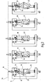
- FIG. 2 The sequence of the piercing movement is illustrated in FIG. 2 in various positions.
- the upper wire 16 is stretched and the lower wire 18 relaxed.
- the lancing element 10 is located with its tip in the zero position 56 of the piercing stroke. Then, the wire 16 is heated by a rush current. Upon reaching the forming temperature, the wire 16 contracts and the lancing element 10 moves forward ( Figure 2b).
- the maximum feed position is achieved in the extended position of the toggle mechanism 22 (FIG. 2 c), in which also the restoring spring 24 is maximally tensioned. Then, the wire 16 does not shorten much further, and the toggle mechanism oscillates under the force of the return spring 24 in the opposite buckling position Fig.
- the further return movement of the lancing element 10 is delayed so as to ensure a sufficient collection time for blood uptake via an integrated in the lancing element, not specifically shown collection channel.
- a quick pain-free puncture can be combined with a collection period of at least one order of magnitude slower in one motion sequence, until finally the end position FIG. 2e is reached.
- the wire 16 can cool slowly while the wire 18 is stretched for the next puncture cycle, without any user intervention would be required.
- FIG. 3 again illustrates the sequence of the puncturing movement in a path-time diagram.
- the fast puncture phase runs until a time t1 in which the maximum puncture depth is reached.
- t1 may be a few milliseconds and the piercing depth a few millimeters.
- an initial rapid return movement takes place up to the time t2, from which the body fluid is slowly absorbed in a suitable retracted collecting depth.
- This collection phase can be in the range of seconds, so that only by capillary action a sufficient amount of liquid is obtained.
- the drive has an electric heating unit 60, which may be designed in accordance with the circuit example FIG. 4.
- the capacitor 64 is charged in series with the resistor 66 and the diode 68 from the voltage source 70, specifically a battery.
- the capacitor 64 can then be discharged via the wire 16, wherein the generated current surge due to the low heat capacity of the thin wire, the heating in a very short period of time is possible. Subsequently, the capacitor 64 is recharged in the zero position, so that in the lower Switch position now the other wire 18 can be activated.
- the second SMA wire 16, 18 used in each case as a braking means can be preheated to a certain preload length.
- the driven by the return spring 24 return movement is then decelerated prematurely and delayed by cooling the wire in question. This can be achieved by controlled heating of the shape memory alloy in the microstructure temperature band or by part heating only a portion of the wire length.
- a typical hysteresis cycle for the temperature-dependent transformation of a shape memory alloy is shown in FIG.
- a phase transition takes place in the metallurgical structure from the martensitic to the austenitic form.
- the reverse transition on cooling is characterized by a hysteretic behavior of the structure-temperature relationship according to curve 72.
- a recovery of tension occurs in the austenite phase and concomitantly a contraction into a "remembered" form.
- the wire length can be deliberately shortened by corresponding expansion to brake during braking the return movement of the lancing element.
- the problem here is the influence of the ambient temperature, which can be minimized by suitable heat insulation of the wire or by choosing a material with high transformation temperature.
- SMA materials exhibit a superelastic behavior under deformation. This effect is caused by stress-induced martensite formation (English: “stress-induced martensite formation”). Because the martensite fraction has been formed above its normal temperature, it immediately converts to undeformed austenite as soon as the external stress ceases. This material property can also be used to return the lancing element 10 without great vibrations dampen. For this purpose, the wire material only has to be heated in the area 74 before the mechanical load is applied, so that this damping then starts.
- the martensite phase has quasi-ideal damping in the expansion interval indicated by dashed lines, which is likewise usable for slowing down the return movement of lancing element 10.
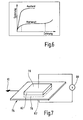
- EAP actuator 76 formed by electro-active polymers (EAP).
- EAP dielectric actuator As an EAP dielectric actuator, this has two opposing surface electrodes 78, which are connected via a suitable voltage source 80 can be acted upon by high voltage.
- the actuator principle is based on a highly dynamic deformation of this elastomeric block 82 when connecting the high voltage to the electrodes 78th These then attract due to electrostatic interaction, whereby the incompressible elastomeric material under transverse deformation of an expansion in the flat configuration 82 'learns.
- elastic electrodes 78 Prerequisite for this are elastic electrodes 78, which is the surface area be able to record.
- the transverse deformation can be used for a linear lancing movement of the lancing element 10.
- a suitable geometry of the elastomer element and the coupling of the lancing element By a suitable geometry of the elastomer element and the coupling of the lancing element, a large stroke in the lancing axis can be achieved.
- Capacitance measurement across the electrodes 78 allows feedback control of the generated motion via a closed loop circuit acting on the high voltage source 80.
Abstract
Description
Die Erfindung betrifft eine Vorrichtung zum Gewinnen von Körperflüssigkeit für Analysezwecke mit einem in ein Körperteil einstechbaren Stechelement und einem Antrieb für eine vorwärts und zurück verlaufende Stechbewegung des Stechelements.The invention relates to a device for obtaining body fluid for analysis purposes with a pierceable into a body part lancing element and a drive for a forward and backward lancing movement of the lancing element.
Solche Entnahmesysteme für kleine Körperflüssigkeitsmengen dienen vor allem Diabetikern zur täglich mehrfach durchgeführten Blutzucker-Selbstkontrolle im Rahmen einer Insulinbehandlung. Für die Gewinnung von Kapillarblut ist es erforderlich, eine Hautöffnung durch einen Einstich zu erzeugen, wobei der Einstichschmerz und die Narbenbildung möglichst weitgehend reduziert werden sollen und zugleich eine hygienische Verfahrensweise gewährleistet sein soll. Damit auch von Laien die erforderlichen Schritte einfach und schnell vorgenommen werden können, ist es wünschenswert, einen weitgehend automatischen Messablauf in einem kompakten Handgerät zu realisieren. Die herkömmlichen Stechapparate sehen federgetriebene Stechantriebe vor, die sich durch eine schnelle Entnahmegeschwindigkeit der gespeicherten Energie auszeichnen. Wenn allerdings die Stechbewegung auch das Sammeln von Blut in so genannten integrierten Systemen umfassen soll, ist eine komplexe Bewegungssteuerung erforderlich, um insbesondere bei kleinen Entnahmemengen eine hohe Verfahrenssicherheit zu gewährleisten.Such removal systems for small amounts of body fluid are used primarily by diabetics for daily repeated blood sugar self-monitoring in the context of insulin treatment. For the extraction of capillary blood, it is necessary to create a skin opening through a puncture, the puncture pain and scarring should be reduced as much as possible and at the same time a hygienic procedure should be guaranteed. So that the required steps can be made easily and quickly by laypersons, it is desirable to realize a largely automatic measurement procedure in a compact hand-held device. The conventional lancing devices provide spring-driven lancing drives, which are characterized by a fast removal rate of stored energy. However, if the lancing movement is also to include the collection of blood in so-called integrated systems, complex motion control is involved necessary to ensure a high level of process safety, especially for small quantities removed.
Ausgehend hiervon liegt der Erfindung die Aufgabe zugrunde, die im Stand der Technik aufgetretenen Nachteile zu vermeiden und mit einfachen Mitteln eine optimierte Gewinnung der Körperflüssigkeit zu ermöglichen.Proceeding from this, the object of the invention is to avoid the disadvantages which have arisen in the prior art and to enable optimized extraction of body fluid with simple means.
Zur Lösung dieser Aufgabe wird die in den unabhängigen Patentansprüchen angegebene Merkmalskombination vorgeschlagen. Vorteilhafte Ausgestaltungen und Weiterbildungen der Erfindung ergeben sich aus den abhängigen Ansprüchen.To solve this problem, the combination of features specified in the independent claims is proposed. Advantageous embodiments and modifications of the invention will become apparent from the dependent claims.
Die Erfindung geht von dem Gedanken aus, einen hochdynamischen Antrieb mit hoher Energiedichte für eine kontrollierte Hin- und Herbewegung bereitzustellen. Dementsprechend wird erfindungsgemäß vorgeschlagen, dass der Antrieb mindestens einen Aktuatordraht auf Basis von Formgedächtnislegierungen zur Steuerung der Stechbewegung über eine Veränderung der Drahtlänge aufweist. Solche so genannten SMA-Aktuatoren zeichnen sich durch Miniaturisierbarkeit und direkte Erzeugung von Linearbewegungen aus. Während mit üblichen stapelförmig gepackten SMA-Aktuatoren eine Hin- sowie anschließende Rückbewegung einer Stecheinheit nicht praxisgerecht realisiert werden kann, hat sich überraschend erwiesen, dass die Energieentnahmegeschwindigkeiten und Bewegungsamplituden von SMA-Drahtaktuatoren hinreichend sind, um eine hochdynamische Bewegung für eine Stech-und Sammelfunktion zu verwirklichen. Durch einfache thermische Beeinflussung kann eine lineare Stechbewegung erzeugt werden, wobei die geringe Wärmemenge, die zur Aufheizung des dünnen Drahtmaterials erforderlich ist, einen schnellen Bewegungsablauf erlaubt.The invention is based on the idea to provide a highly dynamic drive with high energy density for a controlled reciprocation. Accordingly, the invention proposes that the drive has at least one actuator wire based on shape memory alloys for controlling the piercing movement via a change in the wire length. Such so-called SMA actuators are characterized by miniaturization and direct generation of linear movements. While with conventional stacked SMA actuators a forward and subsequent return movement of a lancing unit can not be realized in practice, it has surprisingly been found that the energy extraction speeds and movement amplitudes of SMA wire actuators are sufficient to realize a highly dynamic movement for a lancing and collecting function. By simple thermal influence, a linear lancing movement can be generated, wherein the small amount of heat required to heat the thin wire material, allows a fast movement.
Eine vorteilhafte Ausführung sieht vor, dass der Aktuatordraht durch wärmeaktivierte Kontraktion ein Vorschubmittel für die Vorwärtsbewegung des Stechelements bildet. Dabei können gerade durch die Drahtausführung die kurzen Zeitspannen und hinreichenden Einstechtiefen realisiert werden.An advantageous embodiment provides that the actuator wire forms a feed means for the forward movement of the lancing element by heat-activated contraction. It can be realized just by the wire design, the short periods of time and sufficient Einstechtiefen.
Besonders bevorzugt sind Ausführungen, bei denen der Antrieb einen zwischen dem Aktuatordraht und dem Stechelement angeordneten Bewegungswandler zum Umsetzen einer Längenveränderung des Aktuatordrahts in die Stechbewegung aufweist. Auf diese Weise lassen sich komplexe Bewegungsprofile darstellen, wie sie für eine kombinierte Stech- und Sammelfunktion vorteilhaft sind.Embodiments in which the drive has a motion converter arranged between the actuator wire and the piercing element for converting a change in length of the actuator wire into the piercing movement are particularly preferred. In this way, complex motion profiles can be represented, as they are advantageous for a combined piercing and collecting function.
Vorteilhafterweise umfasst der Antrieb eine Heizeinheit zum Aufheizen des Aktuatordrahts auf eine die Kontraktion der Formgedächtnislegierung bewirkende Heiztemperatur. Dies lässt sich auf einfache Weise dadurch realisieren, dass an dem Aktuatordraht eine einen elektrischen Stromstoß erzeugende Stromquelle, insbesondere ein Kondensator über einen Auslöseschalter angeschlossen ist. Grundsätzlich sind aber auch andere Heizmethoden denkbar, beispielsweise über Heißluft, Wärmestrahlung und Wärmeleitung.Advantageously, the drive comprises a heating unit for heating the actuator wire to a heating temperature causing the contraction of the shape memory alloy. This can be realized in a simple manner by virtue of the fact that a current source generating an electrical surge, in particular, is connected to the actuator wire a capacitor is connected via a release switch. In principle, however, other heating methods are conceivable, for example via hot air, heat radiation and heat conduction.
Zum Einstellen der Stechtiefe und/oder Sammeltiefe des Stechelements kann es von Vorteil sein, wenn der Aktuatordraht vorzugsweise durch verschiebbare elektrische Kontaktstellen über eine veränderliche Länge aufheizbar ist.For adjusting the piercing depth and / or collecting depth of the lancing element, it may be advantageous if the actuator wire can be heated preferably by displaceable electrical contact points over a variable length.
Eine Art von Hybridantrieb lässt sich durch ein bei der Vorwärtsbewegung des Stechelements vorspannbares Rückstellmittel, insbesondere eine Rückstellfeder zur Rückbewegung des Stechelements realisieren.One type of hybrid drive can be realized by means of a restoring means which can be prestressed during the forward movement of the piercing element, in particular a return spring for the return movement of the piercing element.
Eine besonders bevorzugte Ausführung sieht vor, dass der oder ein Aktuatordraht als Bremsmittel die Rückbewegung des Stechelements bremst. Dadurch lässt sich die Blutaufnahme durch langsames Zurückziehen des Stechelements günstig beeinflussen.A particularly preferred embodiment provides that the or an actuator wire as a braking means brakes the return movement of the lancing element. As a result, the blood intake can be favorably influenced by slow retraction of the lancing element.
Eine weitere vorteilhafte Variante sieht zwei wechselweise kontrahierbare Aktuatordrähte zur alternierenden Steuerung der Stechbewegungen in aufeinander folgenden Zyklen vor.A further advantageous variant provides two alternately contractible actuator wires for the alternating control of the lancing movements in successive cycles.
Grundsätzlich ist für eine solche Ausgestaltung ein Drahtmaterial nicht zwingend, so dass ein Erfindungsaspekt auch darin liegt, dass der Antrieb zwei wechselweise kontrahierbare Aktuatoren auf Basis von Formgedächtnislegierungen zur alternierenden Steuerung der Stechbewegungen in aufeinander folgenden Zyklen aufweist.In principle, a wire material is not mandatory for such an embodiment, so that an aspect of the invention is also the fact that the drive has two alternately contractible actuators based on shape memory alloys for alternating control of lancing in successive cycles.
Eine weitere Verbesserung sieht vor, dass ein Aktuatordraht unter Kontraktion die Vorwärtsbewegung des Stechelements treibt und der andere Aktuatordraht unter Expansion die Rückwärtsbewegung bremst.A further improvement provides that an actuator wire drives the forward movement of the piercing element under contraction and the other actuator wire brakes the backward movement under expansion.
Für eine bremsende bzw. dämpfende Wirkung ist es möglich, dass der als Bremsmittel wirkende Aktuatordraht durch Vorheizen auf eine Gefügeumformungstemperatur der Formgedächtnislegierung gezielt verkürzt und unter Abkühlung entsprechend verlängerbar ist.For a braking or damping effect, it is possible for the actuator wire acting as a brake means to be shortened in a targeted manner by preheating to a microstructure transformation temperature of the shape memory alloy and to be correspondingly extendable while cooling.
Gemäß einer weiteren vorteilhafte Ausgestaltung besteht darin, dass der als Bremsmittel wirkende Aktuatordraht abschnittsweise vorgeheizt ist.According to a further advantageous embodiment, the actuator wire acting as the brake means is preheated in sections.
Denkbar ist es auch, dass der Aktuatordraht durch zugspannungsinduzierte Phasenumwandlung der Formgedächtnislegierung als Bremsmittel wirkt.It is also conceivable that the actuator wire acts as a braking means by tension-induced phase transformation of the shape memory alloy.
Für eine hohe Dynamik auch bei der Rückbewegung ist es von besonderem Vorteil, wenn der Antrieb einen in der Achse der Stechbewegung streckbaren Kniehebelmechanismus umfasst. Dabei kann ein Bewegungszyklus dadurch realisiert werden, dass der Kniehebelmechanismus durch den Aktuatordraht in eine Streckstellung und durch ein in der Streckstellung vorgespanntes Rückstellelement in eine Beugestellung bringbar ist.For a high level of dynamics even in the return movement, it is particularly advantageous if the drive comprises a toggle lever mechanism which can be stretched in the axis of the lancing movement. In this case, a movement cycle can be realized in that the toggle mechanism can be brought by the Aktuatordraht in an extended position and by a biased in the extended position return element in a bending position.
Zur Einstellung der Stechtiefe die Lagerstelle eines von dem Stechelement abgewandten Schwenklagers des Kniehebelmechanismus in der Stechachse verstellbar sein.To adjust the puncturing depth, the bearing point of a pivot bearing remote from the lancing element of the toggle mechanism in the lancing axis be adjustable.
Eine Verlangsamung der Rückbewegung des Stechelements lässt sich auch durch ein insbesondere als Kolben-Zylinder-Einheit ausgebildetes Dämpfungselement realisieren.A slowing down of the return movement of the piercing element can also be realized by a damping element designed in particular as a piston-cylinder unit.
Für ein schnelles Aufheizen ist es vorteilhaft, wenn der Durchmesser des Aktuatordrahts kleiner als 1 mm, vorzugsweise kleiner als 0,5 mm ist.For rapid heating, it is advantageous if the diameter of the actuator wire is less than 1 mm, preferably less than 0.5 mm.
Um den Einfluss einer schwankenden Umgebungstemperatur zu minimieren, ist es günstig, wenn die insbesondere als Nickel-Titan-Legierung ausgebildete Formgedächtnislegierung eine Umformungstemperatur von mehr als 100°C besitzt.In order to minimize the influence of a fluctuating ambient temperature, it is advantageous if the shape memory alloy formed in particular as a nickel-titanium alloy has a transformation temperature of more than 100 ° C.
Zur Erhöhung der wirksamen Drahtlänge in gegebenem Bauraum ist es von Vorteil, wenn der Aktuatordraht mehrere über Umlenkmittel geführte, nebeneinander verlaufende Drahtabschnitte aufweist.To increase the effective wire length in a given installation space, it is advantageous if the actuator wire has a plurality of wire sections guided over deflection means and running side by side.
Für eine Verstärkung der Antriebskraft kann es vorteilhaft sein, wenn der Aktuatordraht aus mehreren parallel zueinander verlaufenden Einzeldrähten besteht.For an increase in the driving force, it may be advantageous if the actuator wire consists of a plurality of mutually parallel individual wires.
Vorteilhafterweise erfolgt die Vorwärtsbewegung des Stechelements zur Erzeugung eines Hauteinstichs mindestens eine Größenordnung schneller als die Rückbewegung zum Sammeln von Körperflüssigkeit.Advantageously, the forward movement of the lancing element to create a skin puncture is at least an order of magnitude faster than the return movement for collecting body fluid.
Ein weiterer Erfindungsaspekt umfasst eine Entnahmevorrichtung für Körperflüssigkeit, bei welcher der Antrieb einen durch elektro-aktive Polymere (EAP) gebildeten EAP-Aktuator aufweist. Auch dadurch lässt sich ein hochdynamischer Bewegungsablauf mit geeignetem Stech-und Sammelprofil in kompakter Bauweise ohne motorische Mittel realisieren.A further aspect of the invention comprises a body fluid sampling device in which the drive has an EAP actuator formed by electro-active polymers (EAP). This also makes it possible to realize a highly dynamic movement sequence with a suitable lancing and collecting profile in a compact design without motor means.
Vorteilhafterweise weist der EAP-Aktuator ein zwischen zwei mit Hochspannung beaufschlagbaren Elektroden angeordnetes Elastomerelement auf, wobei eine durch elektrostatische Anziehung der Elektroden bewirkte Verformung des Elastomerelements in die Stechbewegung umsetzbar ist.Advantageously, the EAP actuator has an elastomer element arranged between two electrodes which can be acted upon by high voltage, wherein a deformation of the elastomer element caused by electrostatic attraction of the electrodes can be converted into the lancing movement.
Im Folgenden wird die Erfindung anhand der in der Zeichnung schematisch dargestellten Ausführungsbeispiele näher erläutert. Es zeigen
- Fig. 1
- eine SMA-getriebene Blutentnahmevorrichtung in einer perspektivischen Darstellung;
- Fig. 2
- verschiedene Positionen bei der Stechbewegung in der Seitenansicht der Vorrichtung nach Fig. 1;
- Fig. 3
- ein Zeitdiagramm der vorwärts und zurück verlaufenden Stechbewegung;
- Fig. 4
- ein Schaltbild einer elektrischen Heizeinheit zur Aktivierung eines Antriebs für die Stech-bewegung;
- Fig. 5
- ein Diagramm eines SMA-Hysteresezyklus;
- Fig. 6
- ein typisches Spannungs/Dehnungsdiagramm für SMA-Materialien; und
- Fig. 7
- eine EAP-getriebene Stech/Sammelvorrichtung in einem schematisch stark vereinfachten Schaubild.
- Fig. 1
- an SMA-driven blood sampling device in a perspective view;
- Fig. 2
- different positions in the piercing movement in the side view of the device according to Fig. 1;
- Fig. 3
- a time chart of the forward and backward lancing movement;
- Fig. 4
- a circuit diagram of an electric heating unit for activating a drive for the piercing movement;
- Fig. 5
- a diagram of an SMA hysteresis cycle;
- Fig. 6
- a typical stress / strain diagram for SMA materials; and
- Fig. 7
- an EAP-driven piercing / collecting device in a schematically simplified diagram.
Die in der Zeichnung dargestellten Stech- bzw. Sammelvorrichtungen zum Gewinnen kleiner Mengen von Blut für Blutzuckertests umfassen ein in ein nicht gezeigtes Körperteil (beispielsweise eine Fingerkuppe) einstechbares Stechelement 10, einen Antrieb 12 für eine vor und zurück verlaufende Stechbewegung des Stechelements 10 und eine Aufnahme 14 für den Antrieb und die Linearführung des Stechelements.The lancing devices for obtaining small amounts of blood for blood sugar tests shown in the drawing comprise a lancing
Fig. 1 zeigt einen Testaufbau für einen mittels zwei Aktuatordrähten 16, 18 auf Basis von Formgedächtnislegierungen (Shape Memory Alloys, kurz: SMA) aktuierbaren Antrieb 12. Solche SMA-Aktuatoren erfahren bei Erreichen einer bestimmten Umwandlungstemperatur eine Formänderung, speziell eine Verkürzung der Drahtlänge, die sich zur Erzeugung einer Stech- bzw. Sammelbewegung ausnutzen lässt. Zu diesem Zweck umfasst der Antrieb 12 einen in der Achse 20 der Stechbewegung streckbaren Kniehebelmechanismus 22 als Bewegungswandler. Dieser ist durch die wechselweise kontrahierbaren Aktuatordrähte 16, 18 in aufeinander folgenden Stechzyklen in die Streckstellung bringbar, wobei eine dabei gespannte Rückstellfeder 24 jeweils wieder für die Rückstellung in die Beugestellung sorgt. Optional kann hier ein Dämpfungszylinder 26 eine zusätzliche Dämpfung der Rückbewegung bewirken. Der Dämpfungszylinder 26 besitzt ein Ventil 28, welches die Dämpfungsrichtung steuert, so dass eine ungedämpfte schnelle Vorwärtsbewegung und eine gedämpfte langsamere Rückbewegung der in dem Zylinder geführten Kolbestange 30 erreicht wird.Fig. 1 shows a test setup for a means of two
Die Aktuatordrähte 16, 18 sind an ihren Enden an Spannstücken 32 aufnahmeseitig eingespannt und dabei über Anschlussbuchsen 34 elektrisch kontaktierbar. Ein Mittelstück der Aktuatordrähte 16, 18 ist über einen Umlenkzapfen 36 an jeweils einem Schenkelende eines T-Auslegers 38 des Kniehebelmechanismus 22 geführt, so dass durch zwei nebeneinander verlaufende Drahtabschnitte eine große Drahtlänge erreicht wird. Um eine rasche elektrische Aufheizung mittels Joule-Effekt zu ermöglichen, kann der Drahtdurchmesser kleiner als 0,5 mm gewählt werden. Zur Verringerung des Einflusses schwankender Umgebungstemperaturen kann eine Nickel-Titan-Legierung, insbesondere Nickel-Titan-Hafnium oder Nickel-Titan-Zirkonium mit einer Umformungstemperatur von mehr als 100°C als Drahtmaterial eingesetzt werden.The
Der Kniehebelmechanismus weist zwei parallele Kniehebeltriebe 22 auf, die über ein distales Schwenklager 40 gelenkig an einen Bund 42 der Stange 30 angeschlossen sind und über ein proximales Widerlager 44 bei der Stechbewegung ortsfest abgestützt sind, wobei das die Kniehebel 46, 48 verbindende Kniegelenk 50 frei schwingt. Die Stechtiefe des Stechelements 10 lässt sich mittels einer Stellvorrichtung 52 einstellen, welche die Position des das Widerlager 44 tragenden Zylinders 26 in Richtung der Stechachse 20 festlegt.The toggle mechanism has two
Wie bereits erwähnt, sind die Aktuatordrähte 16, 18 für einen wechselseitigen Antrieb vorgesehen, wobei in der in Fig. 1 gezeigten Stellung der Draht 16 durch wärmeaktivierte Kontraktion ein Vorschubmittel für die Vorwärtsbewegung des Stechelements 10 bildet, während der andere Draht 18 unter Expansion die Rückbewegung des Stechelements 10 bremst bzw. dämpft. Hierbei kann der bremsende Draht 18 eine über die Umlenkstelle 36 über-stehende Schlaufe 54 aufweisen, so dass der Bremseingriff erst nach einem gewissen Rückhub verzögert erfolgt.As already mentioned, the
Der Ablauf der Stechbewegung ist in Fig. 2 in verschiedenen Positionen veranschaulicht. In der Ausgangsposition Fig. 2a ist der obere Draht 16 gespannt und der untere Draht 18 relaxiert. Das Stechelement 10 befindet sich mit seiner Spitze in der Nullposition 56 des Stechhubs. Sodann wird der Draht 16 durch einen Stromstoss erhitzt. Bei Erreichen der Umformungstemperatur kontrahiert der Draht 16 und das Stechelement 10 bewegt sich vorwärts (Fig. 2b). Die maximale Vorschublage wird in der Streckstellung des Kniehebelmechanismus 22 erreicht (Fig. 2c), in welcher auch die Rückstellfeder 24 maximal gespannt ist. Sodann verkürzt sich der Draht 16 nicht wesentlich weiter, und der Kniehebelmechanismus schwingt unter der Kraft der Rückstellfeder 24 in die gegenüberliegende Knickstellung Fig. 2d, in der mittels des Dämpfers 26 und/oder des hinteren Aktuatordrahts 18 die weitere Rückbewegung des Stechelements 10 verzögert wird, um so eine ausreichende Sammelzeit für die Blutaufnahme über einen in dem Stechelement integrierten, nicht eigens gezeigten Sammelkanal zu gewährleisten. Auf diese Weise kann ein schneller schmerzarmer Einstich mit einer mindestens eine Größenordnung langsameren Sammelperiode in einem Bewegungsablauf kombiniert werden, bis schließlich die Endposition Fig. 2e erreicht wird. Dabei kann der Draht 16 langsam auskühlen, während der Draht 18 für den nächsten Stechzyklus gespannt ist, ohne dass ein Benutzereingriff erforderlich wäre.The sequence of the piercing movement is illustrated in FIG. 2 in various positions. In the starting position Fig. 2a, the
Fig. 3 veranschaulicht nochmals den Ablauf der Stechbewegung in einem Weg-Zeit-Diagramm. Die schnelle Einstichphase verläuft bis zu einer Zeit t1, in der die maximale Stechtiefe erreicht ist. Beispielsweise kann t1 wenige Millisekunden und die Stechtiefe einige Millimeter betragen. Anschließend erfolgt eine anfänglich rasche Rückbewegung bis zum Zeitpunkt t2, ab welchem in einer geeigneten zurückgezogenen Sammeltiefe die Körperflüssigkeit langsam aufgenommen wird. Diese Sammelphase kann im Sekundenbereich liegen, so dass auch allein durch Kapillarwirkung eine ausreichende Flüssigkeitsmenge gewonnen wird.FIG. 3 again illustrates the sequence of the puncturing movement in a path-time diagram. The fast puncture phase runs until a time t1 in which the maximum puncture depth is reached. For example, t1 may be a few milliseconds and the piercing depth a few millimeters. Subsequently, an initial rapid return movement takes place up to the time t2, from which the body fluid is slowly absorbed in a suitable retracted collecting depth. This collection phase can be in the range of seconds, so that only by capillary action a sufficient amount of liquid is obtained.
Damit der Kniehebelmechanismus 22 hin und her schwingen kann, muss abwechselnd der eine, dann der andere Draht 16, 18 aufgeheizt werden. Zu diesem Zweck weist der Antrieb eine elektrische Heizeinheit 60 auf, die gemäß dem Schaltungsbeispiel Fig. 4 ausgelegt sein kann. In der gezeigten Nullstellung des Wechselschalters 62 wird der Kondensator 64 in Serie mit dem Widerstand 66 und der Diode 68 aus der Spannungsquelle 70, speziell einer Batterie aufgeladen. In der oberen Schaltstellung des Schalters 62 kann dann der Kondensator 64 über den Draht 16 entladen werden, wobei durch den erzeugten Stromstoss aufgrund der geringen Wärmekapazität des dünnen Drahts das Aufheizen in sehr kurzer Zeitdauer möglich ist. Anschließend wird in der Nullstellung der Kondensator 64 wieder aufgeladen, so dass in der unteren Schaltstellung nunmehr der andere Draht 18 aktiviert werden kann.So that the
Um die langsame Rückbewegung während der Sammelphase zu steuern, kann der jeweils als Bremsmittel eingesetzte zweite SMA-Draht 16, 18 bis zu einer gewissen Vorspannlänge vorgeheizt werden. Die durch die Rückstellfeder 24 getriebene Rückbewegung wird dann vorzeitig abgebremst und unter Abkühlung des betreffenden Drahtes zeitlich verzögert. Dies kann durch kontrolliertes Erhitzen der Formgedächtnislegierung in das Gefügeumformungs-Temperaturband oder durch Teilerhitzen nur eines Teils der Drahtlänge erreicht werden.In order to control the slow return movement during the collection phase, the
Zur näheren Erläuterung des kontrollierten Erhitzens ist in Fig. 5 ein typischer Hysteresezyklus für die temperaturabhängige Umformung einer Formgedächtnislegierung gezeigt. Beim Aufheizen vollzieht sich entsprechend der Kurve 70 ein Phasenübergang in der metallur-gischen Struktur von der martensitischen in die austenitische Form. Der umgekehrte Übergang beim Abkühlen zeichnet sich entsprechend der Kurve 72 durch ein hysteretisches Verhalten der Struktur-Temperatur-Beziehung aus. Durch die Strukturänderung tritt in der Austenitphase eine Spannungserholung und damit einhergehend eine Kontraktion in eine "erinnerte" Form auf. Daraus folgt, dass innerhalb des Umformungstemperaturintervalls zwischen T1 und T2 die Drahtlänge gezielt verkürzt werden kann, um durch entsprechende Expansion bei der Abkühlung die Rückbewegung des Stechelements zu bremsen. Problematisch ist hierbei der Einfluss der Umgebungstemperatur, der durch geeignete Wärmeisolation des Drahts oder durch Wahl eines Materials mit hoher Umwandlungstemperatur minimiert werden kann.For a more detailed explanation of the controlled heating, a typical hysteresis cycle for the temperature-dependent transformation of a shape memory alloy is shown in FIG. Upon heating, according to the
Um solche Probleme zu umgehen, ist es auch denkbar, den jeweils bremsenden bzw. dämpfenden Aktuatordraht nur segmentweise zu erhitzen. Dies lässt sich durch entsprechende elektrische Abgriffe an dem Draht realisieren, die gegebenenfalls verschiebbar angebracht sein können. Das oder die erhitzten Segmente werden dabei in einer Ein/Aus-Aktuierung betrieben, d.h. deutlich über das Umformungstemperaturintervall hinaus erhitzt. Somit wird der Draht immer um dieselbe Länge kontrahiert, welche dann beim Abkühlen als definierter Bremsweg zur Verfügung steht.To circumvent such problems, it is also conceivable to heat the respective braking or damping actuator wire only in segments. This can be realized by appropriate electrical taps on the wire, which may optionally be slidably mounted. The heated segment (s) are operated in an on / off actuation, i. heated well beyond the forming temperature interval. Thus, the wire is always contracted by the same length, which is then available as a defined braking distance during cooling.
In dem in Fig. 5 gestrichelt umrahmten Bereich 74, der sich an das Umformungstemperaturintervall anschließt, zeigen SMA-Materialien unter Deformation ein superelastisches Verhalten. Dieser Effekt wird durch spannungsinduzierte Martensitbildung (Englisch: "stress-induced martensite formation") verursacht. Weil der Martensitanteil oberhalb seiner normalen Temperatur gebildet wurde, wandelt er sich unmittelbar in undeformierten Austenit um, sobald die äußere Belastung wegfällt. Auch diese Materialeigenschaft kann dazu genutzt werden, die Rückbewegung des Stechelements 10 ohne große Vibrationen abzudämpfen. Das Drahtmaterial muss dafür lediglich vor Einsetzen der mechanischen Belastung in den Bereich 74 erhitzt werden, damit diese Dämpfung dann einsetzt.In the
Eine weitere Dämpfungseigenschaft von SMA-Material tritt in der kühleren Martensit-Phase auf, wenngleich weniger effektiv als die spannungsinduzierte Martensitbildung. Entsprechend Fig. 6 besitzt die Martensit-Phase in dem gestrichelt markierten Dehnungsintervall eine quasi-ideale Dämpfung, die ebenfalls für eine Verlangsamung der Rückbewegung des Stechelements 10 nutzbar ist.Another cushioning property of SMA material occurs in the cooler martensite phase, although less effectively than stress-induced martensite formation. According to FIG. 6, the martensite phase has quasi-ideal damping in the expansion interval indicated by dashed lines, which is likewise usable for slowing down the return movement of lancing
Fig. 7 veranschaulicht die prinzipielle Funktionsweise einer Ausführungsform einer Stech- und Sammelvorrichtung basierend auf einem durch elektro-aktive Polymere (EAP) gebildeten EAP-Aktuator 76. Dieser weist als dielektrischer EAP-Aktuator zwei einander gegenüberliegende Flächenelektroden 78 auf, die über eine geeignete Spannungsquelle 80 mit Hochspannung beaufschlagbar sind. Zwischen den Elektroden 78 befindet sich ein E-lastomerblock 82. Das Aktuatorprinzip beruht auf einer hochdynamischen Verformung dieses Elastormerblocks 82 beim Aufschalten der Hochspannung auf die Elektroden 78. Diese ziehen sich dann aufgrund elektrostatischer Wechselwirkung an, wodurch das inkompressible Elastomermaterial unter Querverformung eine Ausdehnung in die flache Konfiguration 82' erfährt. Voraussetzung dafür sind elastische Elektroden 78, welche die Flächenausdehnung aufnehmen können. Die Querverformung kann für eine lineare Stechbewegung des Stechelements 10 genutzt werden. Durch eine geeignete Geometrie des Elastomerelements und der Kopplung des Stechelements kann dabei ein großer Hub in der Stechachse erreicht werden. Eine Kapazitätsmessung über die Elektroden 78 erlaubt eine Feedback-Regelung der erzeugten Bewegung über einen auf die Hochspannungsquelle 80 einwirkenden geschlossenen Regelkreis.7 illustrates the basic mode of operation of an embodiment of a lancing and collecting device based on an
Claims (25)
Priority Applications (6)
| Application Number | Priority Date | Filing Date | Title |
|---|---|---|---|
| EP05020062A EP1764037A1 (en) | 2005-09-15 | 2005-09-15 | Device for extracting body liquids for the purpose of analysis |
| DE502006008887T DE502006008887D1 (en) | 2005-09-15 | 2006-09-14 | DEVICE FOR OBTAINING BODY FLUID FOR ANALYSIS PURPOSES |
| EP06777190A EP1924200B8 (en) | 2005-09-15 | 2006-09-14 | Device for obtaining bodily fluids for analysis purposes |
| PCT/EP2006/008952 WO2007031310A2 (en) | 2005-09-15 | 2006-09-14 | Device for obtaining bodily fluids for analysis purposes |
| AT06777190T ATE497727T1 (en) | 2005-09-15 | 2006-09-14 | DEVICE FOR OBTAINING BODY FLUID FOR ANALYSIS PURPOSES |
| US12/048,798 US20080269639A1 (en) | 2005-09-15 | 2008-03-14 | Device for obtaining bodily fluids for analysis |
Applications Claiming Priority (1)
| Application Number | Priority Date | Filing Date | Title |
|---|---|---|---|
| EP05020062A EP1764037A1 (en) | 2005-09-15 | 2005-09-15 | Device for extracting body liquids for the purpose of analysis |
Publications (1)
| Publication Number | Publication Date |
|---|---|
| EP1764037A1 true EP1764037A1 (en) | 2007-03-21 |
Family
ID=35953929
Family Applications (2)
| Application Number | Title | Priority Date | Filing Date |
|---|---|---|---|
| EP05020062A Withdrawn EP1764037A1 (en) | 2005-09-15 | 2005-09-15 | Device for extracting body liquids for the purpose of analysis |
| EP06777190A Not-in-force EP1924200B8 (en) | 2005-09-15 | 2006-09-14 | Device for obtaining bodily fluids for analysis purposes |
Family Applications After (1)
| Application Number | Title | Priority Date | Filing Date |
|---|---|---|---|
| EP06777190A Not-in-force EP1924200B8 (en) | 2005-09-15 | 2006-09-14 | Device for obtaining bodily fluids for analysis purposes |
Country Status (5)
| Country | Link |
|---|---|
| US (1) | US20080269639A1 (en) |
| EP (2) | EP1764037A1 (en) |
| AT (1) | ATE497727T1 (en) |
| DE (1) | DE502006008887D1 (en) |
| WO (1) | WO2007031310A2 (en) |
Cited By (6)
| Publication number | Priority date | Publication date | Assignee | Title |
|---|---|---|---|---|
| WO2009067325A1 (en) * | 2007-11-02 | 2009-05-28 | Refocus Group, Inc. | Apparatuses and methods for forming incisions in ocular tissue |
| WO2011127346A1 (en) | 2010-04-09 | 2011-10-13 | Facet Technologies, Llc | Lancing device with tethered depth-control mechanism |
| US8597318B2 (en) | 2011-08-08 | 2013-12-03 | Refocus Group, Inc. | Apparatus and method for forming incisions in ocular tissue |
| WO2015032740A1 (en) * | 2013-09-05 | 2015-03-12 | Sanofi-Aventis Deutschland Gmbh | Drive mechanism for a needle insertion arrangement |
| US10085681B2 (en) | 2012-04-11 | 2018-10-02 | Facet Technologies, Llc | Lancing device with moving pivot depth adjust |
| US10806631B2 (en) | 2017-08-23 | 2020-10-20 | Refocus Group, Inc. | Surgical tool for forming incisions in ocular tissue with tip providing visibility and related apparatus and method |
Families Citing this family (8)
| Publication number | Priority date | Publication date | Assignee | Title |
|---|---|---|---|---|
| US20090099437A1 (en) * | 2007-10-11 | 2009-04-16 | Vadim Yuzhakov | Lancing Depth Adjustment Via Moving Cap |
| US8118824B2 (en) * | 2008-09-16 | 2012-02-21 | Roche Diagnostics Operations, Inc. | Magnetic powered lancing drive |
| ATE542478T1 (en) * | 2008-12-02 | 2012-02-15 | Roche Diagnostics Gmbh | DEVICE FOR OBTAINING A BLOOD SAMPLE |
| EP2311373B1 (en) * | 2009-10-15 | 2012-08-01 | Roche Diagnostics GmbH | Piercing system for removal of a body fluid |
| KR101109197B1 (en) * | 2009-12-17 | 2012-01-30 | 국립암센터 | Apparatus for needle insertion |
| JP2019011804A (en) * | 2017-06-29 | 2019-01-24 | 高砂電気工業株式会社 | Shape memory alloy valve device |
| IT201700109554A1 (en) * | 2017-09-29 | 2019-03-29 | Getters Spa | Air bag module |
| CN110613463B (en) * | 2019-10-29 | 2021-11-30 | 南京市儿童医院 | Blood sampling device for neonates |
Citations (4)
| Publication number | Priority date | Publication date | Assignee | Title |
|---|---|---|---|---|
| US20020113499A1 (en) * | 2001-02-22 | 2002-08-22 | Von Behrens Peter E. | SMA actuator with improved temperature control |
| WO2003088835A2 (en) * | 2002-04-19 | 2003-10-30 | Pelikan Technologies, Inc. | Method and apparatus for penetrating tissue |
| US20040098009A1 (en) * | 2002-04-19 | 2004-05-20 | Pelikan Technologies, Inc. | Method and apparatus for body fluid sampling and analyte sensing |
| US20050023086A1 (en) * | 2003-06-30 | 2005-02-03 | Andrei Szilagyi | Shape memory alloy-actuated and bender-actuated helical spring brakes |
Family Cites Families (4)
| Publication number | Priority date | Publication date | Assignee | Title |
|---|---|---|---|---|
| US7017345B2 (en) * | 2002-05-06 | 2006-03-28 | Alfmeier Prazision Ag Baugruppen And Systemlosungen | High stroke, highly integrated SMA actuators |
| US20040010207A1 (en) * | 2002-07-15 | 2004-01-15 | Flaherty J. Christopher | Self-contained, automatic transcutaneous physiologic sensing system |
| US7572237B2 (en) * | 2002-11-06 | 2009-08-11 | Abbott Diabetes Care Inc. | Automatic biological analyte testing meter with integrated lancing device and methods of use |
| US7213736B2 (en) * | 2003-07-09 | 2007-05-08 | Ethicon Endo-Surgery, Inc. | Surgical stapling instrument incorporating an electroactive polymer actuated firing bar track through an articulation joint |
-
2005
- 2005-09-15 EP EP05020062A patent/EP1764037A1/en not_active Withdrawn
-
2006
- 2006-09-14 WO PCT/EP2006/008952 patent/WO2007031310A2/en active Application Filing
- 2006-09-14 DE DE502006008887T patent/DE502006008887D1/en active Active
- 2006-09-14 EP EP06777190A patent/EP1924200B8/en not_active Not-in-force
- 2006-09-14 AT AT06777190T patent/ATE497727T1/en active
-
2008
- 2008-03-14 US US12/048,798 patent/US20080269639A1/en not_active Abandoned
Patent Citations (5)
| Publication number | Priority date | Publication date | Assignee | Title |
|---|---|---|---|---|
| US20020113499A1 (en) * | 2001-02-22 | 2002-08-22 | Von Behrens Peter E. | SMA actuator with improved temperature control |
| WO2002068820A1 (en) * | 2001-02-22 | 2002-09-06 | Nanomuscle, Inc. | Shape memory alloy actuator with improved temperature control |
| WO2003088835A2 (en) * | 2002-04-19 | 2003-10-30 | Pelikan Technologies, Inc. | Method and apparatus for penetrating tissue |
| US20040098009A1 (en) * | 2002-04-19 | 2004-05-20 | Pelikan Technologies, Inc. | Method and apparatus for body fluid sampling and analyte sensing |
| US20050023086A1 (en) * | 2003-06-30 | 2005-02-03 | Andrei Szilagyi | Shape memory alloy-actuated and bender-actuated helical spring brakes |
Cited By (15)
| Publication number | Priority date | Publication date | Assignee | Title |
|---|---|---|---|---|
| KR101503380B1 (en) * | 2007-11-02 | 2015-03-17 | 리포쿠스 그룹 인코포레이티드 | Apparatuses And Methods For Forming Incisions In Ocular Tissue |
| US8083759B2 (en) | 2007-11-02 | 2011-12-27 | Refocus Ocular, Inc. | Apparatuses and methods for forming incisions in ocular tissue |
| CN101854891B (en) * | 2007-11-02 | 2012-07-04 | 重新聚焦集团公司 | Apparatuses and methods for forming incisions in ocular tissue |
| US8460325B2 (en) | 2007-11-02 | 2013-06-11 | Refocus Ocular, Inc. | Apparatuses and methods for forming incisions in ocular tissue |
| WO2009067325A1 (en) * | 2007-11-02 | 2009-05-28 | Refocus Group, Inc. | Apparatuses and methods for forming incisions in ocular tissue |
| US8764780B2 (en) | 2007-11-02 | 2014-07-01 | Refocus Ocular, Inc. | Apparatuses and methods for forming incisions in ocular tissue |
| US8771300B2 (en) | 2007-11-02 | 2014-07-08 | Refocus Ocular, Inc. | Apparatuses and methods for forming incisions in ocular tissue |
| WO2011127346A1 (en) | 2010-04-09 | 2011-10-13 | Facet Technologies, Llc | Lancing device with tethered depth-control mechanism |
| US8512366B2 (en) | 2010-04-09 | 2013-08-20 | Facet Technologies, Llc | Lancing device with tethered depth-control mechanism |
| US8597318B2 (en) | 2011-08-08 | 2013-12-03 | Refocus Group, Inc. | Apparatus and method for forming incisions in ocular tissue |
| US8945166B2 (en) | 2011-08-08 | 2015-02-03 | Refocus Group, Inc. | Apparatus and method for forming incisions in ocular tissue |
| US10085681B2 (en) | 2012-04-11 | 2018-10-02 | Facet Technologies, Llc | Lancing device with moving pivot depth adjust |
| WO2015032740A1 (en) * | 2013-09-05 | 2015-03-12 | Sanofi-Aventis Deutschland Gmbh | Drive mechanism for a needle insertion arrangement |
| US10188806B2 (en) | 2013-09-05 | 2019-01-29 | Sanofi-Aventis Deutschland Gmbh | Drive mechanism for a needle insertion arrangement |
| US10806631B2 (en) | 2017-08-23 | 2020-10-20 | Refocus Group, Inc. | Surgical tool for forming incisions in ocular tissue with tip providing visibility and related apparatus and method |
Also Published As
| Publication number | Publication date |
|---|---|
| EP1924200A2 (en) | 2008-05-28 |
| WO2007031310A2 (en) | 2007-03-22 |
| US20080269639A1 (en) | 2008-10-30 |
| EP1924200B1 (en) | 2011-02-09 |
| WO2007031310A3 (en) | 2007-06-21 |
| DE502006008887D1 (en) | 2011-03-24 |
| EP1924200B8 (en) | 2011-03-23 |
| ATE497727T1 (en) | 2011-02-15 |
Similar Documents
| Publication | Publication Date | Title |
|---|---|---|
| EP1924200B1 (en) | Device for obtaining bodily fluids for analysis purposes | |
| DE60031687T2 (en) | DRIVE FROM A FORM MEMORY ALLOY AND METHOD FOR CONTROLLING | |
| EP1669028B1 (en) | Lancet device for forming an incision and lancet drive sub-assembly | |
| EP1734864B1 (en) | Method and system for taking body fluid | |
| EP1254632B1 (en) | Blood lancet with pivot mechanism | |
| DE102011112290B4 (en) | Actuator with at least one, thermal transducer material having actuator | |
| DE102009012626B4 (en) | Linear guide with braking device | |
| DE102011102597A1 (en) | Thermally activated active material actuator i.e. shape memory alloy actuator, has heat sink that presents thermal conductivity rate greater than ambient rate and engages with active material element to present shorter cooling period | |
| EP2409164B1 (en) | Apparatus and method for electromechanical positioning | |
| EP1091700A1 (en) | Bone distraction device | |
| EP2594312A1 (en) | Device for punctuation of an organic tissue and drive module | |
| EP3191066A1 (en) | Stimulation device with change of shape using shape-memory element | |
| EP3363492B1 (en) | Needle module for a drive-managed device for repeated puncturing of human or animal skin and hand-held device | |
| DE102008003879A1 (en) | Linear drive for driving movable object, comprises piezoactuator which is controlled by controller and mechanical frictional engagement is formed to transfer drive force between transducer and object to be moved | |
| DE102010015447A1 (en) | Modular actuator has shape memory elements that cause translation or rotary movement and adjustable resetting movement of operation element, when transition temperature exceeds | |
| DE102008037082A1 (en) | Lancing device for a blood sampling | |
| DE102009025444A1 (en) | Lancing device with lancet ejection means | |
| EP2193746B1 (en) | Device to obtain a blood sample | |
| DE102010038700A1 (en) | Actuator with shape memory alloy | |
| DE102019117448B3 (en) | Walking drive arrangement and method for its operation | |
| DE102016005003B4 (en) | Braking device for linear axis guided systems | |
| EP1798624A2 (en) | Device for controlling a heat flow | |
| DE102019117447B3 (en) | Electromechanical braking device and method for its operation | |
| WO2013044946A1 (en) | Actuator for generating positioning movements | |
| DE202012101530U1 (en) | actuator |
Legal Events
| Date | Code | Title | Description |
|---|---|---|---|
| PUAI | Public reference made under article 153(3) epc to a published international application that has entered the european phase |
Free format text: ORIGINAL CODE: 0009012 |
|
| AK | Designated contracting states |
Kind code of ref document: A1 Designated state(s): AT BE BG CH CY CZ DE DK EE ES FI FR GB GR HU IE IS IT LI LT LU LV MC NL PL PT RO SE SI SK TR |
|
| AX | Request for extension of the european patent |
Extension state: AL BA HR MK YU |
|
| AKX | Designation fees paid | ||
| STAA | Information on the status of an ep patent application or granted ep patent |
Free format text: STATUS: THE APPLICATION IS DEEMED TO BE WITHDRAWN |
|
| 18D | Application deemed to be withdrawn |
Effective date: 20070923 |
|
| REG | Reference to a national code |
Ref country code: DE Ref legal event code: 8566 |