EP1768356A2 - Portable terminal foldable forming a triangular prism - Google Patents
Portable terminal foldable forming a triangular prism Download PDFInfo
- Publication number
- EP1768356A2 EP1768356A2 EP06019038A EP06019038A EP1768356A2 EP 1768356 A2 EP1768356 A2 EP 1768356A2 EP 06019038 A EP06019038 A EP 06019038A EP 06019038 A EP06019038 A EP 06019038A EP 1768356 A2 EP1768356 A2 EP 1768356A2
- Authority
- EP
- European Patent Office
- Prior art keywords
- housing
- wireless communication
- communication terminal
- portable wireless
- housings
- Prior art date
- Legal status (The legal status is an assumption and is not a legal conclusion. Google has not performed a legal analysis and makes no representation as to the accuracy of the status listed.)
- Granted
Links
Images


Classifications
-
- H—ELECTRICITY
- H04—ELECTRIC COMMUNICATION TECHNIQUE
- H04B—TRANSMISSION
- H04B1/00—Details of transmission systems, not covered by a single one of groups H04B3/00 - H04B13/00; Details of transmission systems not characterised by the medium used for transmission
- H04B1/38—Transceivers, i.e. devices in which transmitter and receiver form a structural unit and in which at least one part is used for functions of transmitting and receiving
-
- H—ELECTRICITY
- H04—ELECTRIC COMMUNICATION TECHNIQUE
- H04M—TELEPHONIC COMMUNICATION
- H04M1/00—Substation equipment, e.g. for use by subscribers
- H04M1/02—Constructional features of telephone sets
- H04M1/0202—Portable telephone sets, e.g. cordless phones, mobile phones or bar type handsets
- H04M1/0206—Portable telephones comprising a plurality of mechanically joined movable body parts, e.g. hinged housings
- H04M1/0247—Portable telephones comprising a plurality of mechanically joined movable body parts, e.g. hinged housings comprising more than two body parts
-
- H—ELECTRICITY
- H04—ELECTRIC COMMUNICATION TECHNIQUE
- H04M—TELEPHONIC COMMUNICATION
- H04M1/00—Substation equipment, e.g. for use by subscribers
- H04M1/02—Constructional features of telephone sets
- H04M1/0202—Portable telephone sets, e.g. cordless phones, mobile phones or bar type handsets
- H04M1/0206—Portable telephones comprising a plurality of mechanically joined movable body parts, e.g. hinged housings
- H04M1/0208—Portable telephones comprising a plurality of mechanically joined movable body parts, e.g. hinged housings characterized by the relative motions of the body parts
- H04M1/0214—Foldable telephones, i.e. with body parts pivoting to an open position around an axis parallel to the plane they define in closed position
-
- H—ELECTRICITY
- H04—ELECTRIC COMMUNICATION TECHNIQUE
- H04M—TELEPHONIC COMMUNICATION
- H04M1/00—Substation equipment, e.g. for use by subscribers
- H04M1/02—Constructional features of telephone sets
- H04M1/0202—Portable telephone sets, e.g. cordless phones, mobile phones or bar type handsets
- H04M1/0206—Portable telephones comprising a plurality of mechanically joined movable body parts, e.g. hinged housings
- H04M1/0208—Portable telephones comprising a plurality of mechanically joined movable body parts, e.g. hinged housings characterized by the relative motions of the body parts
- H04M1/0235—Slidable or telescopic telephones, i.e. with a relative translation movement of the body parts; Telephones using a combination of translation and other relative motions of the body parts
Definitions
- the present invention relates generally to a portable terminal, and in particular, to a portable terminal for enabling convenient Digital Multimedia Broadcasting (DMB) viewing.
- DMB Digital Multimedia Broadcasting
- a portable terminal refers to a device which provides wireless communications between users or between a user and a service provider through a Base Station (BS) or an access point.
- BS Base Station
- a wide range of service contents are provided to users through portable terminals, such as voice call, Short Message Service (SMS), mobile banking, television viewing, on-line games, and Video On Demand (VOD).
- SMS Short Message Service
- VOD Video On Demand
- the portable terminals may be classified into a bar type, a flip type, and a folder type according to their looks.
- the bar-type portable terminal has communication circuits and an input/output device with a transmitter and a receiver in one housing.
- the flip type is formed by adding a flip cover to the configuration of the bar type.
- the folder type is so configured as to be opened or closed along with the rotation of a pair of housings and as to have an input/output device separately in the housings.
- a sliding-type portable terminals increase portability and use convenience and satisfy various user demands.
- While mobile communication services provided through these portable terminals may have been limited to voice call and SMS message transmission at an early developmental stage, expanded services may include, for example, games, transmission of music and moving pictures, on-line games, and multimedia service.
- DMB service may be commercialized using the portable terminals as DMB receivers. Since existing portable terminals are designed to fulfil the functions of voice call and message transmission, for long-time DMB viewing, an additional cradle for mounting a portable terminal therein may be required or a user may have to handhold his portable terminal to place the display at the eye level.
- the displays of the conventional portable terminals may have a large length relative to a width, thus being unsuitable for viewing broadcasting programs. Because the DMB service, like standard terrestrial television broadcasting, may present pictures at an aspect ratio with a relatively large width with respect to a length, broadcast pictures may not be viewed with full utilization of the screen area of the display of the conventional portable terminal.
- a portable terminal includes first, second and third housings.
- the second housing is rotatably engaged with one portion of the first housing.
- the third housing has one end engaged to linearly move closely beneath the rear surface of the second housing and the other end rotatably engaged with the other portion of the first housing.
- the third housing is folded onto the first housing, interposed between the first housing and the second housing, and when the second housing and the third housing rotate away from the first housing, the first, second and third housings form a triangular prism.
- a portable terminal includes first, second and third housings.
- the second housing has an opening penetrating through both surfaces of the second housing and is rotatably engaged with one portion of the first housing.
- the third housing has a display and is rotatably engaged with the other portion of the first housing.
- the second and third housings are foldable to the first housing, and when the second and third housings are folded to the first housing, the display is partially exposed through the opening.
- a portable terminal 100 includes a first housing 101, a second housing 102, and a third housing 103.
- the second and third housings 102 and 103 are rotatably engaged with the first housing 101.
- the portable terminal may be any wireless communication device including but not limited to a mobile station, PDA and computer.
- the third housing 103 is interposed between the first and second housings 101 and 102.
- the second and third housings 102 and 103 rotate, receding from the first housing 101, the first, second and third housings 101, 102 and 103 form a triangular prism.
- the first housing 101 is comprised of a base housing 101a and a cover housing 101b engaged with the base housing 101a.
- the second housing 102 has a rotation housing 102a and a cover plate 102b engaged with the rotation housing 102a.
- the first housing 101 is provided, at one portion thereof, with a first center hinge arm 111 and the second housing 102 is provided, at one portion thereof, with a pair of first side hinge arms 123 facing each other.
- the first side hinge arms 123 are rotatably engaged with both ends of the first center hinge arm 1111 so that the second housing 102 can rotate over the first housing 101.
- Rotation pins 109 can be used to engage the first side hinge arms 123 with the first center hinge arm 111.
- the rotation pins 109 are rotatably engaged with the first side hinge arms 123, fixed to both ends of the first center hinge arm 111, thereby supporting the rotation of the second housing 102.
- the second housing 102 has a keypad, a transmitter and a receiver on one surface 121 thereof to implement the typical communication functionality of the portable terminal 100.
- a small-size display can further be provided on the surface 121 of the second housing 102 to display basic information, for example, the phone number of the other party, antenna transmission/reception sensitivity, date and time.
- Guide rails 167 are provided on the second housing 102.
- the guide rails 167 are installed on the inner surface of the second housing 102, particularly on the inner surface of the cover plate 102a.
- Guide holes 129 are formed on the rotation housing 102a along the length of the guide rails 167. Therefore, as the guide holes 129 are formed on the rear surface of the second housing 102, the guide rails 167 are exposed outward from the second housing 102.
- the guide rails 167 are extended perpendicularly to the hinge axis of the first center hinge arms 111 and the first side hinge arms 123 of the first and second housings 101 and 102.
- the third housing 103 is provided, on one surface thereof, with a large display 131 and at one end thereof, with a pair of second side arms 133 facing each other. As the third housing 103 rotates, the display 131 is opened or closed by the second housing 102. The third housing 103 is rotatably engaged with the other portion of the first housing 101. To engage the third housing 103 with the first housing 101, the portable terminal 100 has a sliding plate 104. That is, the third housing 103 is engaged on the first housing 101 by means of the sliding plate 104.
- the sliding plate 104 faces the inner surface of the cover housing 101b of the first housing 101 and is slidably received into the first housing 101 by the guidance of ribs formed in the base housing 101 a.
- a slide hole 119 of the cover housung 101b is extended lengthwise at the other portion of the first housing 101, for allowing the sliding plate 104 to advance or recede therethrough within the first housing 101.
- the sliding plate 104 is provided, at one end thereof, with a second center hinge arm 141. Since the second center hinge arm 141 is too large to pass through the slide hole 119, the second center hinge arm 141 is kept exposed from the other portion of the first housing 101, even when the sliding plate 104 is inserted into the first housing 101.
- At least one elastic member 143 is mounted in the first housing 101 to exert an elastic force such that the sliding plate 104 is inserted into the first housing 101.
- One end of the elastic member 143 is supported inside the first housing 101 and the other end thereof is supported by the sliding plate 104.
- the positions at which both ends of the elastic member 143 are supported can be easily set by those skilled in the art.
- the third housing 103 is rotatably engaged with the first housing 101, particularly over the sliding plate 104 by means of a rotation pin 109, as easily understood from the engagement mechanism between the first and second housings 101 and 102.
- a known hinge module 105 may be used in engaging the second or third housing 102 or 103 on the first housing 101.
- the third housing 103 is engaged with the first housing 101 by the hinge module 105.
- an accommodation hole 145 is formed at an end of the second center hinge arm 141.
- the hinge module 105 provides a rotation force in a direction to fold or unfold the third housing 103 to or from the first housing 101 according to the rotation angle between the third housing 103 and the first housing 101.
- This hinge module 105 is disclosed in various forms in U.S. Patent No. 6,292,980 issued to the present applicant on September 25, 2001.
- hinge module 105 is confined to engagement between the third housing 103 and the first housing 101 in the preferred embodiment of the present invention, it is obvious that it can also be used to engage the first housing 101 with the second housing 102.
- the other portion of the third housing 103 is so configured that the third housing 103 linearly advances toward or recedes from the hinge engagement between the first housing 101 and second housings 102, closely beneath the rear surface of the second housing 102. This is possible by engaging sliders 106 installed at the other end of the third housing 103 with the guide rails 167 so as to slide along the guide rails 167.
- the sliders 106 are rotatably engaged in engagement grooves 137 formed at the other end of the third housing 103.
- Each of the sliders 106 is provided with a rotation hole 161 and a support pin 165 is extended through the rotation hole 161 such that the slider 106 is rotatably engaged in the engagement groove 137.
- the sliders 106 are installed at both ends of the other end of the third housing 103 and are provided, on the outer surface thereof, with sliding grooves 163 for surrounding the outer circumferential surface of the guide rails 167.
- the sliders 106 slide along the guide rails 167 on the rear surface of the second housing 102, surrounding the outer circumferential surfaces of the guide rails 167 with the sliding grooves 163.
- the sliders 106 are engaged rotatably with the third housing 103 and slidably with the second housing 102, the other portion of the third housing 103 linearly moves closely beneath the rear surface of the second housing 102.
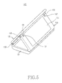
- the second and third housings 102 and 103 As one ends of the second and third housings 102 and 103 are rotatably engaged on the first housing 101 and the other end of the third housing 103 is engaged with the second housing 102 such that it can make a linear movement closely beneath the rear surface of the second housing 102, the second and third housings 102 and 103 each can rotate only to a limited angle in a receding direction from the first housing 101. Consequently, as the second and third housings 102 and 103 rotate, receding from the first housing 101, the portable terminal 100 is posed in the form of a triangular prism as illustrated in FIG. 5.
- the rotation angles of the second and third housings 102 and 103 are determined by the widths of the second and third housings 102 and 103 and the length of the guide holes 129.
- the hinge module 105 installed in the sliding plate 104 exerts a driving force in a direction to fold the third housing 103 toward the first housing 101 or in a direction to retreat the third housing 103 from the first housing 101 according to the rotation angle of the third housing 103, as stated before. If the portable terminal 100 is so configured that the third housing 103 can rotate up to 40 degrees, the hinge module 105 provides a driving force in the direction to fold the third housing 103 toward the first housing 101 in the state where the third housing 103 is rotated from the first housing 101 at or below 20 degrees. If the rotation angle of the third housing 103 exceeds 20 degrees, the hinge module 105 provides a driving force in the direction to retreat the third housing 103 from the first housing 101.
- a rotation angle at which the driving force of the hinge module 105 is changed may vary depending on products.
- FIG. 4 illustrates the portable terminal 100 in which the second and third housings 102 and 103 start to open from the first housing 101.
- the third housing 103 also rotates while the sliders 106 slide along the guide rails 167.
- the hinge module 105 provides its driving force in the direction to fold the third housing 103 toward the first housing 101 until before the third housing 103 rotates to or above a predetermined angle with respect to the first housing 101. Therefore, the driving force of the hinge module 105 imposed on the third housing 103 tends to fold the second housing 102 toward the first housing 101 if the third housing 103 rotates within a predetermined angle range from the first housing 101.
- the driving force of the hinge module 105 is exerted in the direction that makes the second and third housings 102 and 103 unfold from the first housing 101.
- the second and third housings 102 and 103 are rotated until the portable terminal 100 is unfolded in the form of a triangular prism, as illustrated in FIG. 5.
- the use of the hinge module 105 semi-automates the opening of the display 131 on the third housing 103.
- the user can place the first housing 101 on a plane such as a table to conveniently view a broadcasting program such as a DMB program. Since the display 131 is posed with a width larger than a length, the broadcasting program can be viewed with full utilization of the limited area of the display 131.
- FIGs. 6, 7 and 8 sequentially illustrate folding of the second and third housings 102 and 103 toward the first housing 101.
- the user presses the second housing 102 in an advancing direction to the first housing 101 to fold the second and third housings 102 and 103 onto the first housing 101.
- the sliders 106 cannot slide in the guide holes 129. In other words, at the angle A between the second and third housings 102 and 103, the pressure applied on the second housing 102 by the user cannot be transformed to a force to slide the sliders 106.
- the sliding plate 104 slides and the angle A between the second and third housings 102 and 103 becomes smaller.
- the pressure on the second housing 102 is transformed to the force to slide the sliders 106.
- the second housing 102 rotates in a folding direction (3) to the first housing 101 and the sliding plate 104 moves in a receding direction (2) from the first housing 101.
- the third housing 103 also rotates, advancing toward the first housing 101.
- the angle A between the second and third housings 102 and 103 becomes smaller.
- the pressure on the second housing 102 now can be transformed to the force to slide the sliders 106.
- the driving force of the hinge module 105 is exerted in the direction that folds the third housing 103 to the first housing 101.
- An elastic force exerted in an arrowed direction (4) that inserts the sliding plate 104 into the first housing 101 is transformed to a force that moves the sliders 106 toward the hinge engagement between the first and second housings 101 and 102 in an arrowed direction (5).
- the angle A between the second and third housings 102 and 103 becomes much smaller and the driving force of the hinge module 105 and the elastic force on the sliding plate 104 fold the third housing 103 to the first housing 101.
- the closing operation of the display 131 of the third housing 103 is semi-automated by means of the forces of the hinge module 105 and the elastic member 143 of the first housing 101.
- the driving force of the hinge module 105 is exerted in a direction that brings the third housing 103 into close contact with the first housing 101. Therefore, the portable terminal 100 is kept stable in the folded state unless the user rotates the second and third housings 102 and 103.
- FIG. 11 is a perspective view of the portable terminal 100 according to an alternative preferred embodiment of the present invention.
- the difference between the two embodiments of the present invention lies in that the portable terminal 100 is configured to have a display 131 exposed through an opening 211 formed on the second housing 102 in the alternative embodiment.
- the following description is made with the appreciation that the same components as in the first embodiment are denoted by like reference numerals or not denoted and their detailed description is not provided herein.
- the second housing 102 is provided with the opening 211 penetrating through both surfaces thereof.
- the display 131 is exposed through the opening 211.
- the displayed information includes basic communication information and terminal state information, such as date, time, antenna transmission/reception sensitivity, battery status, and an SMS message incoming indication.
- a keypad 215 and a transmitter 213 are provided at one side of the opening 211, and a receiver is provided at the other side of the opening 211.
- the portable terminal 100 takes the form of a bar type in the folded state. The user can enjoy basic communications in the folded state, whereas he can view a broadcasting program conveniently through the display 131 on the third housing 103 when the second and third housings 102 and 103 rotate away from the first housing 101 and thus the housings 101, 102 and 103 form a triangular prism.
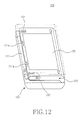
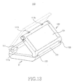
- FIGs. 12 and 13 illustrate the portable terminal 100 according to a further preferred embodiment of the present invention.
- This portable terminal 100 is characterized in that it further includes fixing protrusions 111a and fixing grooves 111b.
- the following description is made with the appreciation that the same components as those in the above two embodiments are denoted by like reference numerals or not denoted and their detailed description is not provided.
- the second housing 102 common to the three embodiments is not shown herein in order to make the fixing protrusions 111a and the fixing grooves 11b more conspicuous.
- the fixing protrusions 111a are formed on the first housing 101, and the fixing grooves 111b are formed at one end of the third housing 103.
- the fixing protrusions 111a are preferably formed on the inner surface of the first center hinge arm 111 of the first housing 101, at which the first center hinge arm 111 faces the end of the third housing 103 only when the third housing 103 is folded on the first housing 101.
- the fixing protrusions 111a are engaged with the fixing grooves 111b, thereby keeping the portable terminal 100 stable in the folded state.
- the user rotates the second housing 102 in a unfolding direction from the first housing 101.
- the sliders 106 slide on the rear surface of the second housing 102, making the third housing 103 unfold from the first housing 101.
- the sliding plate 104 slides such that the fixing protrusions 111a are released from the engagement with the fixing grooves 111b.
- the hinge module 105 rotatably engaged with the sliding plate 104 exerts a driving force such that the third housing 103 rotates farther from the first housing 101.
- the second and third housings rotatably engaged with the first housing form a triangular prism, when they unfold to an open state from the first housing.
- the portable terminal can be placed on a plane like a table. This advantage makes it convenient to view a broadcasting program like a DMB program through the display on the third housing of the portable terminal.
- the portable terminal can be placed in the posture that renders the width of the display to be larger than the length, the broadcasting program can be viewed with full utilization of the limited area of the display.
Abstract
Description
- The present invention relates generally to a portable terminal, and in particular, to a portable terminal for enabling convenient Digital Multimedia Broadcasting (DMB) viewing.
- Typically, a portable terminal refers to a device which provides wireless communications between users or between a user and a service provider through a Base Station (BS) or an access point. A wide range of service contents are provided to users through portable terminals, such as voice call, Short Message Service (SMS), mobile banking, television viewing, on-line games, and Video On Demand (VOD).
- The portable terminals may be classified into a bar type, a flip type, and a folder type according to their looks. The bar-type portable terminal has communication circuits and an input/output device with a transmitter and a receiver in one housing. The flip type is formed by adding a flip cover to the configuration of the bar type. The folder type is so configured as to be opened or closed along with the rotation of a pair of housings and as to have an input/output device separately in the housings. A sliding-type portable terminals increase portability and use convenience and satisfy various user demands.
- While mobile communication services provided through these portable terminals may have been limited to voice call and SMS message transmission at an early developmental stage, expanded services may include, for example, games, transmission of music and moving pictures, on-line games, and multimedia service.
- DMB service may be commercialized using the portable terminals as DMB receivers. Since existing portable terminals are designed to fulfil the functions of voice call and message transmission, for long-time DMB viewing, an additional cradle for mounting a portable terminal therein may be required or a user may have to handhold his portable terminal to place the display at the eye level. In addition, the displays of the conventional portable terminals may have a large length relative to a width, thus being unsuitable for viewing broadcasting programs. Because the DMB service, like standard terrestrial television broadcasting, may present pictures at an aspect ratio with a relatively large width with respect to a length, broadcast pictures may not be viewed with full utilization of the screen area of the display of the conventional portable terminal.
- According to one aspect of the present invention, a portable terminal includes first, second and third housings. The second housing is rotatably engaged with one portion of the first housing. The third housing has one end engaged to linearly move closely beneath the rear surface of the second housing and the other end rotatably engaged with the other portion of the first housing. The third housing is folded onto the first housing, interposed between the first housing and the second housing, and when the second housing and the third housing rotate away from the first housing, the first, second and third housings form a triangular prism.
- According to another aspect of the present invention, a portable terminal includes first, second and third housings. The second housing has an opening penetrating through both surfaces of the second housing and is rotatably engaged with one portion of the first housing. The third housing has a display and is rotatably engaged with the other portion of the first housing. The second and third housings are foldable to the first housing, and when the second and third housings are folded to the first housing, the display is partially exposed through the opening.
- The above and other objects, features and advantages of the present invention will become more apparent from the following detailed description when taken in conjunction with the accompanying drawings in which:
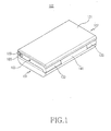
- FIG. 1 is a perspective view of a portable terminal according to a preferred embodiment of the present invention;
- FIG. 2 is an exploded perspective view of the portable terminal illustrated in FIG. 1;
- FIG. 3 is an exploded perspective view of the portable terminal illustrated in FIG. 1, taken from a different direction;
- FIGs. 4 and 5 are perspective views sequentially illustrating rotation of second and third housings in the portable terminal illustrated in FIG. 1;
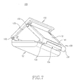
- FIGs. 6 and 7 are perspective views illustrating folding of the second and third housings in the portable terminal illustrated in FIG. 5;
- FIG. 8 is a side view of the portable terminal illustrated in FIG. 6;
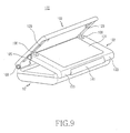
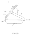
- FIG. 9 is a perspective view illustrating the second and third housings rotated in a folding direction in the portable terminal illustrated in FIG. 6;
- FIG. 10 is a side view of the portable terminal illustrated in FIG. 9;
- FIG. 11 is a perspective view of a portable terminal according to an alternative preferred embodiment of the present invention;
- FIG. 12 is a partial perspective view of a portable terminal according to a further preferred embodiment of the present invention; and
- FIG. 13 is a perspective view illustrating a third housing rotated in a receding direction from a first housing in the portable terminal illustrated in FIG. 12.
- Preferred embodiments of the present invention will be described herein below with reference to the accompanying drawings. In the following description, well-known functions or constructions are not described in detail since they would obscure the invention in unnecessary detail.
- Referring to FIGs. 1, 2 and 3, a
portable terminal 100 according to a preferred embodiment of the present invention includes afirst housing 101, asecond housing 102, and athird housing 103. The second andthird housings first housing 101. The portable terminal may be any wireless communication device including but not limited to a mobile station, PDA and computer. When the second andthird housings first housing 101, thethird housing 103 is interposed between the first andsecond housings third housings first housing 101, the first, second andthird housings - The
first housing 101 is comprised of abase housing 101a and acover housing 101b engaged with thebase housing 101a. Thesecond housing 102 has arotation housing 102a and acover plate 102b engaged with therotation housing 102a. - The
first housing 101 is provided, at one portion thereof, with a firstcenter hinge arm 111 and thesecond housing 102 is provided, at one portion thereof, with a pair of first side hingearms 123 facing each other. The firstside hinge arms 123 are rotatably engaged with both ends of the first center hinge arm 1111 so that thesecond housing 102 can rotate over thefirst housing 101.Rotation pins 109 can be used to engage the firstside hinge arms 123 with the firstcenter hinge arm 111. Therotation pins 109 are rotatably engaged with the firstside hinge arms 123, fixed to both ends of the firstcenter hinge arm 111, thereby supporting the rotation of thesecond housing 102. - While not shown, the
second housing 102 has a keypad, a transmitter and a receiver on onesurface 121 thereof to implement the typical communication functionality of theportable terminal 100. A small-size display can further be provided on thesurface 121 of thesecond housing 102 to display basic information, for example, the phone number of the other party, antenna transmission/reception sensitivity, date and time. -
Guide rails 167 are provided on thesecond housing 102. Theguide rails 167 are installed on the inner surface of thesecond housing 102, particularly on the inner surface of thecover plate 102a.Guide holes 129 are formed on therotation housing 102a along the length of theguide rails 167. Therefore, as theguide holes 129 are formed on the rear surface of thesecond housing 102, theguide rails 167 are exposed outward from thesecond housing 102. Theguide rails 167 are extended perpendicularly to the hinge axis of the first center hingearms 111 and the first side hingearms 123 of the first andsecond housings - The
third housing 103 is provided, on one surface thereof, with alarge display 131 and at one end thereof, with a pair ofsecond side arms 133 facing each other. As thethird housing 103 rotates, thedisplay 131 is opened or closed by thesecond housing 102. Thethird housing 103 is rotatably engaged with the other portion of thefirst housing 101. To engage thethird housing 103 with thefirst housing 101, theportable terminal 100 has asliding plate 104. That is, thethird housing 103 is engaged on thefirst housing 101 by means of thesliding plate 104. - The sliding
plate 104 faces the inner surface of thecover housing 101b of thefirst housing 101 and is slidably received into thefirst housing 101 by the guidance of ribs formed in thebase housing 101 a. Aslide hole 119 of thecover housung 101b is extended lengthwise at the other portion of thefirst housing 101, for allowing the slidingplate 104 to advance or recede therethrough within thefirst housing 101. - The sliding
plate 104 is provided, at one end thereof, with a secondcenter hinge arm 141. Since the secondcenter hinge arm 141 is too large to pass through theslide hole 119, the secondcenter hinge arm 141 is kept exposed from the other portion of thefirst housing 101, even when the slidingplate 104 is inserted into thefirst housing 101. - At least one
elastic member 143 is mounted in thefirst housing 101 to exert an elastic force such that the slidingplate 104 is inserted into thefirst housing 101. One end of theelastic member 143 is supported inside thefirst housing 101 and the other end thereof is supported by the slidingplate 104. The positions at which both ends of theelastic member 143 are supported can be easily set by those skilled in the art. - The
third housing 103 is rotatably engaged with thefirst housing 101, particularly over the slidingplate 104 by means of arotation pin 109, as easily understood from the engagement mechanism between the first andsecond housings hinge module 105 may be used in engaging the second orthird housing first housing 101. In the embodiment of the present invention, thethird housing 103 is engaged with thefirst housing 101 by thehinge module 105. To accommodate thehinge module 105, anaccommodation hole 145 is formed at an end of the secondcenter hinge arm 141. Thehinge module 105 provides a rotation force in a direction to fold or unfold thethird housing 103 to or from thefirst housing 101 according to the rotation angle between thethird housing 103 and thefirst housing 101. Thishinge module 105 is disclosed in various forms inU.S. Patent No. 6,292,980 issued to the present applicant on September 25, 2001. - While the use of the
hinge module 105 is confined to engagement between thethird housing 103 and thefirst housing 101 in the preferred embodiment of the present invention, it is obvious that it can also be used to engage thefirst housing 101 with thesecond housing 102. - Meanwhile, the other portion of the
third housing 103 is so configured that thethird housing 103 linearly advances toward or recedes from the hinge engagement between thefirst housing 101 andsecond housings 102, closely beneath the rear surface of thesecond housing 102. This is possible by engagingsliders 106 installed at the other end of thethird housing 103 with theguide rails 167 so as to slide along the guide rails 167. - The
sliders 106 are rotatably engaged inengagement grooves 137 formed at the other end of thethird housing 103. Each of thesliders 106 is provided with arotation hole 161 and asupport pin 165 is extended through therotation hole 161 such that theslider 106 is rotatably engaged in theengagement groove 137. Thesliders 106 are installed at both ends of the other end of thethird housing 103 and are provided, on the outer surface thereof, with slidinggrooves 163 for surrounding the outer circumferential surface of the guide rails 167. Thus thesliders 106 slide along the guide rails 167 on the rear surface of thesecond housing 102, surrounding the outer circumferential surfaces of theguide rails 167 with the slidinggrooves 163. - Because the
sliders 106 are engaged rotatably with thethird housing 103 and slidably with thesecond housing 102, the other portion of thethird housing 103 linearly moves closely beneath the rear surface of thesecond housing 102. - As one ends of the second and
third housings first housing 101 and the other end of thethird housing 103 is engaged with thesecond housing 102 such that it can make a linear movement closely beneath the rear surface of thesecond housing 102, the second andthird housings first housing 101. Consequently, as the second andthird housings first housing 101, theportable terminal 100 is posed in the form of a triangular prism as illustrated in FIG. 5. The rotation angles of the second andthird housings third housings - The
hinge module 105 installed in the slidingplate 104 exerts a driving force in a direction to fold thethird housing 103 toward thefirst housing 101 or in a direction to retreat thethird housing 103 from thefirst housing 101 according to the rotation angle of thethird housing 103, as stated before. If theportable terminal 100 is so configured that thethird housing 103 can rotate up to 40 degrees, thehinge module 105 provides a driving force in the direction to fold thethird housing 103 toward thefirst housing 101 in the state where thethird housing 103 is rotated from thefirst housing 101 at or below 20 degrees. If the rotation angle of thethird housing 103 exceeds 20 degrees, thehinge module 105 provides a driving force in the direction to retreat thethird housing 103 from thefirst housing 101. A rotation angle at which the driving force of thehinge module 105 is changed may vary depending on products. - FIG. 4 illustrates the
portable terminal 100 in which the second andthird housings first housing 101. When a user rotates thesecond housing 102 in an unfolding direction from thefirst housing 101 in order to open the second andthird housings third housing 103 also rotates while thesliders 106 slide along the guide rails 167. As described earlier, thehinge module 105 provides its driving force in the direction to fold thethird housing 103 toward thefirst housing 101 until before thethird housing 103 rotates to or above a predetermined angle with respect to thefirst housing 101. Therefore, the driving force of thehinge module 105 imposed on thethird housing 103 tends to fold thesecond housing 102 toward thefirst housing 101 if thethird housing 103 rotates within a predetermined angle range from thefirst housing 101. - As the second and
third housings first housing 101 at or above the predetermined angle, the driving force of thehinge module 105 is exerted in the direction that makes the second andthird housings first housing 101. Hence, even though the user does not further rotate the second orthird housing third housings portable terminal 100 is unfolded in the form of a triangular prism, as illustrated in FIG. 5. - Consequently, the use of the
hinge module 105 semi-automates the opening of thedisplay 131 on thethird housing 103. - When the
display 131 is opened, the user can place thefirst housing 101 on a plane such as a table to conveniently view a broadcasting program such as a DMB program. Since thedisplay 131 is posed with a width larger than a length, the broadcasting program can be viewed with full utilization of the limited area of thedisplay 131. - FIGs. 6, 7 and 8 sequentially illustrate folding of the second and
third housings first housing 101. Referring to FIG. 8, in the state where the second andthird housings first housing 101, the user presses thesecond housing 102 in an advancing direction to thefirst housing 101 to fold the second andthird housings first housing 101. - Since the
second housing 102 is almost at the right angle A with thethird housing 103, thesliders 106 cannot slide in the guide holes 129. In other words, at the angle A between the second andthird housings second housing 102 by the user cannot be transformed to a force to slide thesliders 106. - In folding the second and
third housings plate 104 slides and the angle A between the second andthird housings second housing 102 is transformed to the force to slide thesliders 106. - When the user presses the
second housing 102 in an arrowed direction (1), thesecond housing 102 rotates in a folding direction (3) to thefirst housing 101 and the slidingplate 104 moves in a receding direction (2) from thefirst housing 101. As the slidingplate 104 recedes from thefirst housing 101, thethird housing 103 also rotates, advancing toward thefirst housing 101. As the second andthird housings first housing 101, the angle A between the second andthird housings - Referring to FIGs. 9 and 10, as the angle A becomes smaller, the pressure on the
second housing 102 now can be transformed to the force to slide thesliders 106. Simultaneously, as the angle between the first andthird housings hinge module 105 is exerted in the direction that folds thethird housing 103 to thefirst housing 101. An elastic force exerted in an arrowed direction (4) that inserts the slidingplate 104 into thefirst housing 101 is transformed to a force that moves thesliders 106 toward the hinge engagement between the first andsecond housings - As the other portion of the
third housing 103 advances toward the hinge engagement between the first andsecond housings sliders 106, the angle A between the second andthird housings hinge module 105 and the elastic force on the slidingplate 104 fold thethird housing 103 to thefirst housing 101. - Consequently, the closing operation of the
display 131 of thethird housing 103 is semi-automated by means of the forces of thehinge module 105 and theelastic member 143 of thefirst housing 101. - When the second and
third housings first housing 101, the driving force of thehinge module 105 is exerted in a direction that brings thethird housing 103 into close contact with thefirst housing 101. Therefore, theportable terminal 100 is kept stable in the folded state unless the user rotates the second andthird housings - FIG. 11 is a perspective view of the
portable terminal 100 according to an alternative preferred embodiment of the present invention. The difference between the two embodiments of the present invention lies in that theportable terminal 100 is configured to have adisplay 131 exposed through anopening 211 formed on thesecond housing 102 in the alternative embodiment. The following description is made with the appreciation that the same components as in the first embodiment are denoted by like reference numerals or not denoted and their detailed description is not provided herein. - The
second housing 102 is provided with theopening 211 penetrating through both surfaces thereof. When the second andthird housings first housing 101, thedisplay 131 is exposed through theopening 211. Thus, the user can view information displayed on thedisplay 131 even in the folded state. The displayed information includes basic communication information and terminal state information, such as date, time, antenna transmission/reception sensitivity, battery status, and an SMS message incoming indication. - A
keypad 215 and atransmitter 213 are provided at one side of theopening 211, and a receiver is provided at the other side of theopening 211. Hence, theportable terminal 100 takes the form of a bar type in the folded state. The user can enjoy basic communications in the folded state, whereas he can view a broadcasting program conveniently through thedisplay 131 on thethird housing 103 when the second andthird housings first housing 101 and thus thehousings - FIGs. 12 and 13 illustrate the
portable terminal 100 according to a further preferred embodiment of the present invention. Thisportable terminal 100 is characterized in that it further includes fixingprotrusions 111a and fixinggrooves 111b. The following description is made with the appreciation that the same components as those in the above two embodiments are denoted by like reference numerals or not denoted and their detailed description is not provided. Also, thesecond housing 102 common to the three embodiments is not shown herein in order to make the fixingprotrusions 111a and the fixing grooves 11b more conspicuous. - The fixing
protrusions 111a are formed on thefirst housing 101, and the fixinggrooves 111b are formed at one end of thethird housing 103. The fixingprotrusions 111a are preferably formed on the inner surface of the firstcenter hinge arm 111 of thefirst housing 101, at which the firstcenter hinge arm 111 faces the end of thethird housing 103 only when thethird housing 103 is folded on thefirst housing 101. - When the
third housing 103 is folded on thefirst housing 101, the fixingprotrusions 111a are engaged with the fixinggrooves 111b, thereby keeping theportable terminal 100 stable in the folded state. To unfold thethird housing 103, the user rotates thesecond housing 102 in a unfolding direction from thefirst housing 101. At the same time, thesliders 106 slide on the rear surface of thesecond housing 102, making thethird housing 103 unfold from thefirst housing 101. - Along with the rotation of the
third housing 103 from thefirst housing 101 in the unfolding direction, the slidingplate 104 slides such that the fixingprotrusions 111a are released from the engagement with the fixinggrooves 111b. - With full release of the fixing
protrusions 111a from the fixing grooves 11b, thehinge module 105 rotatably engaged with the slidingplate 104 exerts a driving force such that thethird housing 103 rotates farther from thefirst housing 101. - In accordance with the present invention as described above, the second and third housings rotatably engaged with the first housing form a triangular prism, when they unfold to an open state from the first housing. Thus, the portable terminal can be placed on a plane like a table. This advantage makes it convenient to view a broadcasting program like a DMB program through the display on the third housing of the portable terminal. In addition, since the portable terminal can be placed in the posture that renders the width of the display to be larger than the length, the broadcasting program can be viewed with full utilization of the limited area of the display.
- While the invention has been shown and described with reference to certain preferred embodiments thereof, it will be understood by those skilled in the art that various changes in form and details may be made therein without departing from the spirit and scope of the invention as defined by the appended claims.
Claims (22)
- A portable wireless communication wireless communication terminal comprising:a first housing;a second housing rotatably engaged with one portion of the first housing; anda third housing having one end engaged to linearly move closely beneath a rear surface of the second housing and the opposite end rotatably engaged with the other portion of the first housing,wherein when the third housing is folded onto the first housing, the third housing is interposed between the first housing and the second housing, and when the second housing and the third housing rotate away from the first housing, the first, second and third housings form a triangular prism.
- The portable wireless communication terminal of claim 1, wherein when the second housing and the third housing rotate away from the first housing, the third housing supports the rear surface of the second housing.
- The portable wireless communication terminal of claim 1, further comprising:at least one guide rail installed on the second housing; anda slider installed at the one end of the third housing and slidably engaged with the at least one guide rail,wherein when the second housing and the third housing rotate away from the first housing, the slider slides along the at least one guide rail.
- The portable wireless communication terminal of claim 3, further comprising a guide hole formed on the rear surface of the second housing,
wherein the at least one guide rail is provided on an inner surface of the second housing and exposed from the rear surface of the second housing through the guide hole. - The portable wireless communication terminal of claim 1, wherein the third housing comprises:a slider installed to slide on the rear surface of the second housing; andan engagement groove formed at the one end of the third housing and engaged with the slider so that the slider is partially received in the engagement groove and can rotate.
- The portable wireless communication terminal of claim 1, further comprising:a first center hinge arm formed at the one portion of the first housing; anda pair of first side hinge arms formed facing each other at one portion of the second housing,wherein the first side hinge arms are rotatably engaged with both ends of the first center hinge arm.
- The portable wireless communication terminal of claim 6, further comprising:a fixing protrusion formed on the first center hinge arm; anda fixing groove formed on the third housing,wherein when the third housing is folded onto the first housing, the fixing protrusion is engaged in the fixing groove.
- The portable wireless communication terminal of claim 7, wherein the fixing protrusion is formed on an inner surface of the first center hinge arm and the fixing groove is formed at the one end of the third housing.
- The portable wireless communication terminal of claim 1, further comprising a display installed on one surface of the third housing, the display being exposed when the second and third housings rotate away from the first housing.
- The portable wireless communication terminal of claim 1, further comprising a plurality of rotation pins rotatably engaged with the second and third housings, respectively, and fixed onto the first housing, for supporting the rotation of the second and third housings with respect to the first housing.
- The portable wireless communication terminal of claim 1, further comprising a sliding plate installed to be slidable on the first housing,
wherein the third housing is rotatably engaged with the sliding plate. - The portable wireless communication terminal of claim 11, further comprising:a second center hinge arm formed at an end of the sliding plate; anda pair of second side hinge arms facing each other at the opposite end of the third housing,wherein the second side hinge arms are rotatably engaged with both ends of the second center hinge arm.
- The portable wireless communication terminal of claim 11, further comprising a slide hole formed at the other portion of the first housing,
wherein the sliding plate is inserted into or receded from the first housing through the slide hole. - The portable wireless communication terminal of claim 13, wherein when the second and third housings are folded onto the first housing, the sliding plate is retracted into the first housing and the one end of the third housing advances toward the engagement between the first and second housings.
- The portable wireless communication terminal of claim 13, further comprising at least one elastic member having one end supported inside the first housing and the other end supported by the sliding plate, the elastic member being adapted to exert an elastic force in a direction to insert the sliding plate into the first housing.
- A portable wireless communication terminal comprising:a first housing;a second housing having an opening penetrating through opposite surfaces of the second housing and rotatably engaged with one portion of the first housing; anda third housing having a display and rotatably engaged with the other portion of the first housing,wherein the second and third housings are foldable onto the first housing, and when the second and third housings are folded onto the first housing, the display is partially exposed through the opening.
- The portable wireless communication terminal of claim 16, wherein one portion of the third housing is rotatably engaged with the first housing and the opposite portion of the third housing is engaged to linearly move closely beneath a rear surface of the second housing.
- The portable wireless communication terminal of claim 16, further comprising a sliding plate installed to be slidable on the first housing,
wherein the third housing is rotatably engaged with the sliding plate. - The portable wireless communication terminal of claim 18, further comprising:a second center hinge arm formed at an end of the sliding plate; anda pair of second side hinge arms facing each other at the one portion of the third housing,wherein the second side hinge arms are rotatably engaged with both ends of the second center hinge arm.
- The portable wireless communication terminal of claim 19, further comprising a hinge module accommodated in the second center hinge arm, the hinge module being adapted for exerting a driving force in a direction to fold the third housing onto the first housing or in a direction to retreat the third housing from the first housing according to a rotation angle of the third housing.
- The portable wireless communication terminal of claim 16, further comprising:at least one guide rail installed on the second housing; anda slider installed at one end of the third housing and slidably engaged with the at least one guide rail,wherein when the second housing and the third housing rotate away from the first housing, the slider slides along the at least one guide rail.
- The portable wireless communication terminal of claim 21, further comprising a guide hole formed on a rear surface of the second housing, wherein the at least one guide rail is provided on an inner surface of the second housing and exposed from the rear surface of the second housing through the guide hole.
Applications Claiming Priority (1)
| Application Number | Priority Date | Filing Date | Title |
|---|---|---|---|
| KR1020050089867A KR100744295B1 (en) | 2005-09-27 | 2005-09-27 | Portable terminal |
Publications (3)
| Publication Number | Publication Date |
|---|---|
| EP1768356A2 true EP1768356A2 (en) | 2007-03-28 |
| EP1768356A3 EP1768356A3 (en) | 2007-05-23 |
| EP1768356B1 EP1768356B1 (en) | 2012-01-11 |
Family
ID=37579055
Family Applications (1)
| Application Number | Title | Priority Date | Filing Date |
|---|---|---|---|
| EP06019038A Expired - Fee Related EP1768356B1 (en) | 2005-09-27 | 2006-09-12 | Portable terminal foldable forming a triangular prism |
Country Status (4)
| Country | Link |
|---|---|
| US (1) | US7813775B2 (en) |
| EP (1) | EP1768356B1 (en) |
| KR (1) | KR100744295B1 (en) |
| CN (1) | CN100583661C (en) |
Cited By (2)
| Publication number | Priority date | Publication date | Assignee | Title |
|---|---|---|---|---|
| US11340657B2 (en) | 2013-08-02 | 2022-05-24 | Semiconductor Energy Laboratory Co., Ltd. | Display device |
| US11714542B2 (en) | 2013-11-29 | 2023-08-01 | Semiconductor Energy Laboratory Co., Ltd. | Data processing device and driving method thereof for a flexible touchscreen device accepting input on the front, rear and sides |
Families Citing this family (28)
| Publication number | Priority date | Publication date | Assignee | Title |
|---|---|---|---|---|
| US8548927B2 (en) * | 2001-07-10 | 2013-10-01 | Xatra Fund Mx, Llc | Biometric registration for facilitating an RF transaction |
| KR100726468B1 (en) * | 2005-06-27 | 2007-06-11 | (주)케이티에프테크놀로지스 | Hinge Device and Mobile Terminal thereof |
| KR100678200B1 (en) * | 2005-06-30 | 2007-02-02 | 삼성전자주식회사 | Sliding/folding combination type mobile phone |
| TWI281811B (en) * | 2005-07-01 | 2007-05-21 | Wintek Corp | Mobile communication device |
| US8005518B1 (en) * | 2006-12-21 | 2011-08-23 | Adobe Systems Incorporated | Configurable multi-dimensional media device |
| TWI321980B (en) * | 2007-01-22 | 2010-03-11 | Qisda Corp | Foldable mobile electronic device |
| US8082631B2 (en) * | 2007-06-19 | 2011-12-27 | Nokia Corporation | Folding mechanism for compact device |
| TWI339328B (en) * | 2007-10-17 | 2011-03-21 | Inventec Corp | Slide type portable electronic device |
| KR101501771B1 (en) * | 2008-07-11 | 2015-03-12 | 삼성전자주식회사 | Portable type electronic apparatus |
| TWI376928B (en) * | 2010-07-29 | 2012-11-11 | Htc Corp | Handheld electronic device |
| CN102347996B (en) * | 2010-08-03 | 2014-10-01 | 宏达国际电子股份有限公司 | Hand-hold digital apparatus |
| WO2012017270A1 (en) * | 2010-08-05 | 2012-02-09 | Nokia Corporation | An apparatus |
| TWI415553B (en) * | 2011-01-06 | 2013-11-11 | Htc Corp | Handheld electronic device |
| KR101839615B1 (en) * | 2011-04-14 | 2018-03-19 | 삼성전자주식회사 | Portable communication device having flexible display |
| USD766894S1 (en) * | 2013-07-01 | 2016-09-20 | Lg Innotek Co., Ltd. | Router |
| WO2015008680A1 (en) * | 2013-07-19 | 2015-01-22 | Semiconductor Energy Laboratory Co., Ltd. | Data processing device |
| US20160323430A1 (en) * | 2014-02-01 | 2016-11-03 | Patrick J. Fiori | Mounting Device |
| US9395765B2 (en) | 2014-07-31 | 2016-07-19 | Dell Products, Lp | Unibody construction triangular chassis |
| KR101779012B1 (en) * | 2014-08-15 | 2017-09-18 | 주식회사 가난한동지들 | Flexible display apparatus with ability of sliding during a folding and unfolding process |
| USD789925S1 (en) * | 2015-06-26 | 2017-06-20 | Intel Corporation | Electronic device with foldable display panels |
| KR102164704B1 (en) * | 2015-11-13 | 2020-10-12 | 삼성전자주식회사 | Electronic device with metal frame antenna |
| US10564674B2 (en) * | 2016-09-01 | 2020-02-18 | Sharp Kabushiki Kaisha | Information processing device |
| CN107358824B (en) * | 2017-07-24 | 2019-06-11 | 包头轻工职业技术学院 | Solar energy language learning all-in-one machine and its langue leaning system |
| USD902880S1 (en) * | 2019-06-03 | 2020-11-24 | Crestron Electronics, Inc. | All-in-one speakerphone console |
| USD902879S1 (en) * | 2019-06-03 | 2020-11-24 | Crestron Electronics, Inc. | All-in-one speakerphone device |
| USD913260S1 (en) * | 2019-06-18 | 2021-03-16 | Mitel Networks Corporation | Conference unit |
| USD928735S1 (en) * | 2019-08-23 | 2021-08-24 | Lg Electronics Inc. | Speaker |
| CN110410413A (en) * | 2019-08-23 | 2019-11-05 | 东莞市环力智能科技有限公司 | A kind of folding hinge applied to mobile terminal |
Citations (2)
| Publication number | Priority date | Publication date | Assignee | Title |
|---|---|---|---|---|
| US5260998A (en) | 1990-09-07 | 1993-11-09 | Fujitsu Limited | Folding portable telephone set |
| WO2003081880A1 (en) | 2002-03-21 | 2003-10-02 | Nokia Corporation | Mobile electronic device having a pivoted display |
Family Cites Families (8)
| Publication number | Priority date | Publication date | Assignee | Title |
|---|---|---|---|---|
| JP2658928B2 (en) | 1994-11-30 | 1997-09-30 | 日本電気株式会社 | Portable communication device |
| US5926364A (en) * | 1997-05-30 | 1999-07-20 | International Business Machines Corporation | Tri-fold personal computer with touchpad and keyboard |
| MXPA01011556A (en) * | 2000-03-14 | 2002-07-30 | Samsung Electronics Co Ltd | Personal digital assistant telephone combination device. |
| KR100374771B1 (en) * | 2001-05-17 | 2003-03-04 | 삼성전자주식회사 | Portable composite mobile terminal having portable phone and portable information terminal |
| DE60129056T2 (en) * | 2001-12-20 | 2008-02-21 | Nokia Corporation | MOBILEND WITH FOLDABLE FUNCTION COVER |
| JP3849623B2 (en) | 2002-09-05 | 2006-11-22 | 日本電気株式会社 | Mobile communication device |
| KR100640379B1 (en) | 2003-11-01 | 2006-10-30 | 삼성전자주식회사 | Portable terminal and sliding module thereof |
| US20060183435A1 (en) * | 2005-02-14 | 2006-08-17 | Chicony Electronics Co., Ltd. | Keyboard structure |
-
2005
- 2005-09-27 KR KR1020050089867A patent/KR100744295B1/en active IP Right Grant
-
2006
- 2006-02-01 US US11/344,005 patent/US7813775B2/en not_active Expired - Fee Related
- 2006-02-23 CN CN200610057734A patent/CN100583661C/en not_active Expired - Fee Related
- 2006-09-12 EP EP06019038A patent/EP1768356B1/en not_active Expired - Fee Related
Patent Citations (2)
| Publication number | Priority date | Publication date | Assignee | Title |
|---|---|---|---|---|
| US5260998A (en) | 1990-09-07 | 1993-11-09 | Fujitsu Limited | Folding portable telephone set |
| WO2003081880A1 (en) | 2002-03-21 | 2003-10-02 | Nokia Corporation | Mobile electronic device having a pivoted display |
Cited By (3)
| Publication number | Priority date | Publication date | Assignee | Title |
|---|---|---|---|---|
| US11340657B2 (en) | 2013-08-02 | 2022-05-24 | Semiconductor Energy Laboratory Co., Ltd. | Display device |
| US11836007B2 (en) | 2013-08-02 | 2023-12-05 | Semiconductor Energy Laboratory Co., Ltd. | Display device |
| US11714542B2 (en) | 2013-11-29 | 2023-08-01 | Semiconductor Energy Laboratory Co., Ltd. | Data processing device and driving method thereof for a flexible touchscreen device accepting input on the front, rear and sides |
Also Published As
| Publication number | Publication date |
|---|---|
| US7813775B2 (en) | 2010-10-12 |
| US20070072657A1 (en) | 2007-03-29 |
| CN1941644A (en) | 2007-04-04 |
| EP1768356A3 (en) | 2007-05-23 |
| KR20070035238A (en) | 2007-03-30 |
| CN100583661C (en) | 2010-01-20 |
| KR100744295B1 (en) | 2007-07-30 |
| EP1768356B1 (en) | 2012-01-11 |
Similar Documents
| Publication | Publication Date | Title |
|---|---|---|
| EP1768356B1 (en) | Portable terminal foldable forming a triangular prism | |
| EP1773031B1 (en) | Portable communication apparatus with display positionable at an angle | |
| EP1898606B1 (en) | Hinge device having a plurality of axes for a portable terminal and a connection member having the plurality of axes | |
| EP1758343A2 (en) | Hinge device for portable terminal and portable terminal having the same | |
| EP1638295B1 (en) | Portable apparatus with slidable housing parts and a rotatable housing part | |
| US20040137940A1 (en) | Portable wireless terminal device | |
| EP1806909B1 (en) | Portable communication terminal for games and user interfacing device thereof | |
| US20070293286A1 (en) | Sliding module for mobile phone | |
| EP1773030A2 (en) | Foldable portable terminal with a hinge which allows several angle positions of the two housings | |
| US20080076480A1 (en) | Swing-type mobile communication terminal and swing device thereof | |
| EP1684491A2 (en) | Hinge device for mobile terminal | |
| US20070184882A1 (en) | Portable communication terminal for games | |
| KR100630138B1 (en) | Hinge device for portable terminal | |
| US7873396B2 (en) | Portable terminal with hinge stopper | |
| US20050124395A1 (en) | Portable communication apparatus and method thereof | |
| KR20060081448A (en) | Slide opening/closing type mobile phone | |
| EP1848183B1 (en) | Hinge device for portable terminal | |
| KR100899741B1 (en) | Sliding type portable terminal | |
| KR200370668Y1 (en) | Mobile terminal of slide type movable the right and left | |
| KR100630137B1 (en) | Portable terminal wiht rotation restriction device | |
| KR100651538B1 (en) | Portable terminal | |
| KR20090045600A (en) | Portable communication device | |
| KR20090066668A (en) | Hinge apparatus for portable terminal | |
| KR20080107791A (en) | Hinge apparatus for portable terminal | |
| KR20090019170A (en) | Portable communication device |
Legal Events
| Date | Code | Title | Description |
|---|---|---|---|
| PUAI | Public reference made under article 153(3) epc to a published international application that has entered the european phase |
Free format text: ORIGINAL CODE: 0009012 |
|
| 17P | Request for examination filed |
Effective date: 20060912 |
|
| AK | Designated contracting states |
Kind code of ref document: A2 Designated state(s): AT BE BG CH CY CZ DE DK EE ES FI FR GB GR HU IE IS IT LI LT LU LV MC NL PL PT RO SE SI SK TR |
|
| AX | Request for extension of the european patent |
Extension state: AL BA HR MK YU |
|
| PUAL | Search report despatched |
Free format text: ORIGINAL CODE: 0009013 |
|
| AK | Designated contracting states |
Kind code of ref document: A3 Designated state(s): AT BE BG CH CY CZ DE DK EE ES FI FR GB GR HU IE IS IT LI LT LU LV MC NL PL PT RO SE SI SK TR |
|
| AX | Request for extension of the european patent |
Extension state: AL BA HR MK YU |
|
| 17Q | First examination report despatched |
Effective date: 20071219 |
|
| AKX | Designation fees paid |
Designated state(s): DE FR GB |
|
| GRAP | Despatch of communication of intention to grant a patent |
Free format text: ORIGINAL CODE: EPIDOSNIGR1 |
|
| GRAS | Grant fee paid |
Free format text: ORIGINAL CODE: EPIDOSNIGR3 |
|
| GRAA | (expected) grant |
Free format text: ORIGINAL CODE: 0009210 |
|
| AK | Designated contracting states |
Kind code of ref document: B1 Designated state(s): DE FR GB |
|
| REG | Reference to a national code |
Ref country code: GB Ref legal event code: FG4D |
|
| REG | Reference to a national code |
Ref country code: DE Ref legal event code: R096 Ref document number: 602006026932 Country of ref document: DE Effective date: 20120315 |
|
| RAP2 | Party data changed (patent owner data changed or rights of a patent transferred) |
Owner name: SAMSUNG ELECTRONICS CO., LTD. |
|
| PLBE | No opposition filed within time limit |
Free format text: ORIGINAL CODE: 0009261 |
|
| STAA | Information on the status of an ep patent application or granted ep patent |
Free format text: STATUS: NO OPPOSITION FILED WITHIN TIME LIMIT |
|
| 26N | No opposition filed |
Effective date: 20121012 |
|
| REG | Reference to a national code |
Ref country code: DE Ref legal event code: R097 Ref document number: 602006026932 Country of ref document: DE Effective date: 20121012 |
|
| REG | Reference to a national code |
Ref country code: FR Ref legal event code: PLFP Year of fee payment: 11 |
|
| REG | Reference to a national code |
Ref country code: FR Ref legal event code: PLFP Year of fee payment: 12 |
|
| REG | Reference to a national code |
Ref country code: FR Ref legal event code: PLFP Year of fee payment: 13 |
|
| REG | Reference to a national code |
Ref country code: DE Ref legal event code: R119 Ref document number: 602006026932 Country of ref document: DE |
|
| PG25 | Lapsed in a contracting state [announced via postgrant information from national office to epo] |
Ref country code: DE Free format text: LAPSE BECAUSE OF NON-PAYMENT OF DUE FEES Effective date: 20200401 |
|
| PGFP | Annual fee paid to national office [announced via postgrant information from national office to epo] |
Ref country code: FR Payment date: 20200824 Year of fee payment: 15 Ref country code: GB Payment date: 20200824 Year of fee payment: 15 |
|
| GBPC | Gb: european patent ceased through non-payment of renewal fee |
Effective date: 20210912 |
|
| PG25 | Lapsed in a contracting state [announced via postgrant information from national office to epo] |
Ref country code: GB Free format text: LAPSE BECAUSE OF NON-PAYMENT OF DUE FEES Effective date: 20210912 Ref country code: FR Free format text: LAPSE BECAUSE OF NON-PAYMENT OF DUE FEES Effective date: 20210930 |