EP1770644A2 - Method and apparatus for determining tax of a vehicle - Google Patents
Method and apparatus for determining tax of a vehicle Download PDFInfo
- Publication number
- EP1770644A2 EP1770644A2 EP06023640A EP06023640A EP1770644A2 EP 1770644 A2 EP1770644 A2 EP 1770644A2 EP 06023640 A EP06023640 A EP 06023640A EP 06023640 A EP06023640 A EP 06023640A EP 1770644 A2 EP1770644 A2 EP 1770644A2
- Authority
- EP
- European Patent Office
- Prior art keywords
- vehicle
- region
- tax
- information
- taxing
- Prior art date
- Legal status (The legal status is an assumption and is not a legal conclusion. Google has not performed a legal analysis and makes no representation as to the accuracy of the status listed.)
- Withdrawn
Links
Images


Classifications
-
- G—PHYSICS
- G07—CHECKING-DEVICES
- G07B—TICKET-ISSUING APPARATUS; FARE-REGISTERING APPARATUS; FRANKING APPARATUS
- G07B15/00—Arrangements or apparatus for collecting fares, tolls or entrance fees at one or more control points
- G07B15/06—Arrangements for road pricing or congestion charging of vehicles or vehicle users, e.g. automatic toll systems
- G07B15/063—Arrangements for road pricing or congestion charging of vehicles or vehicle users, e.g. automatic toll systems using wireless information transmission between the vehicle and a fixed station
-
- G—PHYSICS
- G01—MEASURING; TESTING
- G01C—MEASURING DISTANCES, LEVELS OR BEARINGS; SURVEYING; NAVIGATION; GYROSCOPIC INSTRUMENTS; PHOTOGRAMMETRY OR VIDEOGRAMMETRY
- G01C21/00—Navigation; Navigational instruments not provided for in groups G01C1/00 - G01C19/00
- G01C21/26—Navigation; Navigational instruments not provided for in groups G01C1/00 - G01C19/00 specially adapted for navigation in a road network
-
- G—PHYSICS
- G01—MEASURING; TESTING
- G01C—MEASURING DISTANCES, LEVELS OR BEARINGS; SURVEYING; NAVIGATION; GYROSCOPIC INSTRUMENTS; PHOTOGRAMMETRY OR VIDEOGRAMMETRY
- G01C22/00—Measuring distance traversed on the ground by vehicles, persons, animals or other moving solid bodies, e.g. using odometers, using pedometers
- G01C22/02—Measuring distance traversed on the ground by vehicles, persons, animals or other moving solid bodies, e.g. using odometers, using pedometers by conversion into electric waveforms and subsequent integration, e.g. using tachometer generator
-
- G—PHYSICS
- G06—COMPUTING; CALCULATING OR COUNTING
- G06Q—INFORMATION AND COMMUNICATION TECHNOLOGY [ICT] SPECIALLY ADAPTED FOR ADMINISTRATIVE, COMMERCIAL, FINANCIAL, MANAGERIAL OR SUPERVISORY PURPOSES; SYSTEMS OR METHODS SPECIALLY ADAPTED FOR ADMINISTRATIVE, COMMERCIAL, FINANCIAL, MANAGERIAL OR SUPERVISORY PURPOSES, NOT OTHERWISE PROVIDED FOR
- G06Q30/00—Commerce
- G06Q30/02—Marketing; Price estimation or determination; Fundraising
- G06Q30/0283—Price estimation or determination
- G06Q30/0284—Time or distance, e.g. usage of parking meters or taximeters
-
- G—PHYSICS
- G06—COMPUTING; CALCULATING OR COUNTING
- G06Q—INFORMATION AND COMMUNICATION TECHNOLOGY [ICT] SPECIALLY ADAPTED FOR ADMINISTRATIVE, COMMERCIAL, FINANCIAL, MANAGERIAL OR SUPERVISORY PURPOSES; SYSTEMS OR METHODS SPECIALLY ADAPTED FOR ADMINISTRATIVE, COMMERCIAL, FINANCIAL, MANAGERIAL OR SUPERVISORY PURPOSES, NOT OTHERWISE PROVIDED FOR
- G06Q30/00—Commerce
- G06Q30/04—Billing or invoicing
-
- G—PHYSICS
- G06—COMPUTING; CALCULATING OR COUNTING
- G06Q—INFORMATION AND COMMUNICATION TECHNOLOGY [ICT] SPECIALLY ADAPTED FOR ADMINISTRATIVE, COMMERCIAL, FINANCIAL, MANAGERIAL OR SUPERVISORY PURPOSES; SYSTEMS OR METHODS SPECIALLY ADAPTED FOR ADMINISTRATIVE, COMMERCIAL, FINANCIAL, MANAGERIAL OR SUPERVISORY PURPOSES, NOT OTHERWISE PROVIDED FOR
- G06Q40/00—Finance; Insurance; Tax strategies; Processing of corporate or income taxes
- G06Q40/12—Accounting
- G06Q40/123—Tax preparation or submission
-
- G—PHYSICS
- G08—SIGNALLING
- G08G—TRAFFIC CONTROL SYSTEMS
- G08G1/00—Traffic control systems for road vehicles
- G08G1/20—Monitoring the location of vehicles belonging to a group, e.g. fleet of vehicles, countable or determined number of vehicles
- G08G1/207—Monitoring the location of vehicles belonging to a group, e.g. fleet of vehicles, countable or determined number of vehicles with respect to certain areas, e.g. forbidden or allowed areas with possible alerting when inside or outside boundaries
Definitions
- This invention relates to determining tax of a vehicle, and more particularly to a system for determining tax of a vehicle using a positioning system.
- Mobile positioning technology has advanced substantially over the past decade. Many cars, trucks, airplanes, boats, and other vehicles are equipped with devices that provide convenient and reliable mobile positioning using either networks of satellite-based and land-based transceivers or an on-board positioning sensor, such as an inertial navigation system or a dead reckoning system.
- tax determinations were based upon manual reporting and charting of vehicle positions, or recreation of the miles traveled in taxing regions after a trip.
- one way to determine tax for a vehicle is to estimate the number of miles traveled by the vehicle based upon a corresponding distance taken along a preferred route on a map. This approach, however, may not be suitable for particular applications that require more accuracy in the determination of tax. Consequently, a need has arisen for an apparatus and method that accurately determines tax of a vehicle.
- operators of commercial vehicles may also require a way of reporting this tax to a remote location. For example, a cellular telephone in a vehicle offers a convenient communications link to report a determined tax.
- One aspect of the present invention provides a system for determining a tax of a vehicle using positioning technology.
- an apparatus on a vehicle for determining a tax for the vehicle includes a positioning device.
- the positioning device determines a plurality of vehicle positions along a route traveled by the vehicle.
- a memory stores geographic information defining a plurality of regions.
- a processor is coupled to the positioning device and the memory. The processor receives vehicle positions from the positioning device and geographic information from the memory. The processor determines the distance traveled by the vehicle in the regions in response to the vehicle positions and the geographic information.
- a method for determining a tax for a vehicle traveling through a plurality of taxing regions includes determining a plurality of vehicle positions. Each vehicle position is associated with a taxing region. The tax in each taxing region is determined in response to the vehicle positions associated with that taxing region.
- Important technical features of the present invention include improving the accuracy of determining the distance traveled or tax for a vehicle passing through regions using a positioning system.
- the present invention provides determination of the tax on the vehicle or transmission of vehicle position information for determination at a remote location.
- Other important technical advantages include reporting tax information to a central location using a wireless communications network, such as the cellular telephone network.
- Another important technical advantage of the present invention includes consolidating tax determinations with the generation of billing information.
- Further technical advantages include determining tax of a vehicle based upon actual miles traveled by the vehicle.
- Yet another important technical feature of the present invention includes taking into consideration any deviation from a predetermined route when determining distance and tax.
- Another important technical advantage of the invention includes reducing the human error associated with determining distance traveled or tax.
- Other technical advantages are readily apparent to one skilled in the art from the following figures, description, and claims.
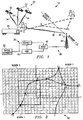
- FIGURE 1 illustrates a system 10 for determining the tax of a vehicle 20 traveling from a point of origin X (located in a taxing region 1) to a destination Y (located in a taxing region 2) across a regional boundary 1-2.
- System 10 includes vehicle 20 equipped with a mobile unit 22, a dispatch 30, and a communications link 40.
- System 10 provides an accurate determination of tax for vehicle 20 traveling along route X-Y for each of taxing regions 1 and 2.
- System 10 may also be used to determine the distance vehicle 20 travels in different regions, without calculating any associated tax. Therefore, all discussions below that relate to determining a tax for vehicle 20 apply equally to determining the distance vehicle 20 travels in any geographic regions for reasons other than tax computation.
- FIGURE 1 shows mobile unit 22 on vehicle 20.
- the present invention contemplates mobile unit 22 being carried by all types of vehicles, including cars, trucks, airplanes, barges, boats, railcars, truck-trailers, or any other moveable object for which it is desirable to determine a tax based upon distance traveled within a taxing region.
- the taxing regions may be countries, regions, districts, states, counties, cities, particular roads or any other region that may charge a tax based on fuel consumption, road usage, or other activity relating to distance traveled or roads traveled along in the region.
- Each taxing region may have its own tax structure.
- the tax rate in region 1 may differ from the tax rate in region 2.
- each region may contain toll and non-toll road designations, which may also impact the determination of tax.
- Mobile unit 22 comprises an odometer 109 (FIGURE 9) operable to measure the distance traveled by vehicle 20.
- Odometer 109 can be the odometer originally included in vehicle 20.
- odometer 109 can be an odometer that is more integral to mobile unit 22 than vehicle 20.
- odometer 109 provides distance information that is used by mobile unit 22 to determine tax for vehicle 20.
- Odometer 109 is an important technical aspect of the present invention because many taxing authorities currently accept odometer readings as an accurate measurement of distance traveled by a vehicle.
- mobile unit 22 may use an approved mileage database, such as those provided by Rand-McNally and others, to determine distance traveled.
- mobile unit 22 determines the position of vehicle 20.
- mobile unit 22 comprises a mobile positioning receiver 80 (FIGURE 9) operable to receive positioning information from positioning system 50.
- Mobile unit 22 receives positioning information over positioning information streams 54 from a plurality of satellites 52.
- Mobile unit 22 determines its position fix using information from positioning information streams 54.
- the positioning information comprises accurate satellite positioning information transmitted by satellites 52 and pseudorange data represented by the time of arrival of positioning information streams 54 at mobile unit 22.
- Positioning system 50 is illustrated as a satellite-based radio navigation system, such as the NAVSTAR global positioning system (GPS).
- GPS global positioning system
- the description uses the NAVSTAR GPS as a representative positioning system 50, but any land-based or satellite-based system may be used.
- positioning system 50 may be a land-based LORAN-C, a space-based GLONASS, or any other appropriate positioning technology.
- positioning system 50 comprises a plurality of satellites 52.
- positioning system 50 comprises a plurality of space-based or land-based transmitters that emit positioning information.
- Satellites 52 maintain accurate and synchronized time and simultaneously transmit positioning information that contains satellite specific and system information required by mobile unit 22 to determine the position fix of vehicle 20.
- the positioning information transmitted by satellites 52 may include high precision clock and ephemeris data for a particular satellite, low precision clock and ephemeris data for every satellite in a constellation ("almanac data"), health and configuration status for all satellites, user text messages, and other parameters describing operation of positioning system 50.
- Positioning system 50 may also comprise additional satellites and one or more positioning receivers.
- the additional satellites may also communicate positioning information to mobile unit 22.
- a positioning receiver 46 may be mounted on a receiver site 44, that is part of communications link 40, to implement differential GPS techniques. Positioning receiver 46 generates correction data that enables mobile unit 22 to more accurately determine the position fix of vehicle 20. Positioning receiver 46 transmits the correction data to mobile unit 22 over any suitable link, such as a vehicle information stream 48.
- mobile unit 22 can generate positioning information itself using an on-board positioning sensor.
- an inertial navigation system on vehicle 20 integrates accelerations imparted to vehicle 20 to determine current position.
- a dead reckoning system computes vehicle location based on compass orientation and distance traveled at that orientation.
- a dead reckoning system on vehicle 20 includes a direction finder, such as a compass, integrated with a distance sensor, such as odometer 109 or a tire rotation counter, to track the location of vehicle 20 and determine its current position.
- mobile unit 22 determines the position fixes of vehicle 20.
- These position fixes may comprise standard geographical coordinates such as latitude and longitude.
- the interval of time between determinations of a position fix may be configurable by either mobile unit 22 or dispatch 30.
- the determinations of a position fix may also be continuous. As discussed below, this interval of time dictates the accuracy of the determinations of distance traveled and tax of vehicle 20 in a taxing region.
- the present invention contemplates that additional processing of information and determining of the distance traveled and tax in a taxing region may be performed on vehicle 20 by mobile unit 22 or at a remote location, such as dispatch 30 or a host 35.
- mobile unit 22 determines the distance traveled and tax of vehicle 20 based upon the position fixes, the distance measured by odometer 109, or other information that may be contained within mobile unit 22. After mobile unit 22 has made these determinations, this information can be transmitted to dispatch 30 or host 35 using communications link 40.
- dispatch 30 or host 35 performs the determination of distance traveled and tax after mobile unit 22 has transmitted vehicle information, including the position fixes and/or the distance measured by odometer 109, to the remote location.
- Mobile unit 22 thus includes a transceiver 94 (FIGURE 9) through which mobile unit 22 transmits vehicle information to a remote location.
- mobile unit 22 initiates transmission of information to dispatch 30 or host 35 based on some configurable condition, such as a predetermined reporting interval, a full memory buffer, a store and forward routine, or a minimum signal strength received from communications link 40.
- Communications link 40 is coupled to mobile unit 22 on vehicle 20 and allows communication between mobile unit 22 and a remote location, such as dispatch 30 or host 35.
- communications link 40 comprises a cellular telephone network. More specifically, communications link 40 comprises at least one receiver site 44 operable to receive vehicle information from mobile unit 22 and a mobile telecommunications switching office (MTSO) 42 coupling receiver site 44 to dispatch 30.
- Mobile unit 22 determines position fixes and distances, and sends these fixes and distances along with other information to receiver site 44 over vehicle information stream 48.
- MTSO 42 coupled to receiver site 44, routes the vehicle information to dispatch 30 or host 35.
- Vehicle information may be encoded using traditional data encoders, such as a modem or a dual-tone multifrequency (DTMF) coder/decoder 110 (FIGURE 9).
- DTMF dual-tone multifrequency
- communications link 40 may be one or a combination of dedicated telephone lines, switched telephone lines, microwave communications links, satellite-based communications links, specialized mobile radio (SMR), enhanced specialized mobile radio (ESMR), a personal communications service (PCS), a citizen's band (CB), a dedicated radio system, such as those used by police and fire fighters, or any other suitable communications link that allows mobile unit 22 to transmit data to or receive data from dispatch 30 or host 35.
- Communications link 40 may also be an SS7 backbone link or similar network for linking land-line or cellular switches in a public switched telephone network (PSTN). Such a link allows components of the PSTN to share information for validation, roaming, billing, call routing, and other functions.
- Communications link 40 may also include intelligence to route information generated at mobile unit 22, dispatch 30, or host 35 to multiple selected sites.
- vehicle information stream 48 may be the control channel, paging channel, part of a seized voice or data channel, or overhead message stream currently implemented in cellular telephone technology.
- the control channel provides paging of incoming calls, hand-off instructions, and other features of the cellular telephone network, but may be modified by one skilled in the art to include transmission of vehicle information.
- Vehicle information stream 48 may also be implemented using any other analog or digital communications link between mobile unit 22 and receiver site 44, whether or not the communications link requires seizing of a voice or data channel, and whether or not a data encoder is used.
- Receiver sites 44 are operable to emit signals to mobile unit 22.
- Mobile unit 22 may then alternatively tune between several signals emitted by receiver sites 44 to determine the strongest signal, usually relating to the nearest receiver site 44.
- Mobile unit 22 establishes communication with that receiver site 44.
- CDPD cellular digital packet data
- CDMA code division multiple access
- TDMA time division multiple access
- Mobile unit 22 may send vehicle information to receiver site 44 in one large packet or in several smaller packets interspersed with other data used for mobile communications.
- the vehicle information may be packaged in existing, but unused, bytes of the overhead message stream or in a dedicated protocol.
- One possible implementation would place vehicle information in the extended protocol described in the EIA/TIA-533 mobile communications standard, which provides for bidirectional communication between mobile unit 22 and receiver site 44.
- dispatch 30 and host 35 can communicate with mobile unit 22.
- Host 35 performs the management and control functions for one or more fleets of trucks. Therefore, system 10 may include many hosts 35 associated with trucking companies, delivery services, or other organizations with vehicles 20 equipped with mobile units 22. Host 35 may receive vehicle information directly from communications link 40. If distance and tax for vehicles 20 have not been determined, host 35 may make these determinations. Alternatively, dispatch 30 may receive and process vehicle information from communications link 40 and then route such information to host 35. Furthermore, host 35 can transmit information to mobile unit 22 either directly using communications link 40 or indirectly through dispatch 30. For example, host 35 may generate destination information for vehicle 20 and transmit this information over a communications link to dispatch 30.
- Such destination information may include one or more destinations, appointment information such as a corresponding appointment time for each destination specified, routing information, information regarding tasks to be performed at each destination specified, average travel time to each destination, rush hour and traffic information, and weather information.
- Dispatch 30 collects destination information from several hosts 35 and transmits this information to vehicles 20. Alternatively, host 35 may transmit destination information to vehicles 20 over communications link 40. In essence, some of the functions performed by dispatch 30 may be distributed among several hosts 35. For clarity, the remainder of this description will focus primarily on the functionality of dispatch 30, but it is understood that host 35 can perform some or all of the functions performed by dispatch 30.
- Dispatch 30 receives the vehicle information generated by mobile unit 22 for vehicle 20 using communications link 40.
- dispatch 30 contains a modem or DTMF coder/decoder 120 (FIGURE 10) that receives vehicle information from MTSO 42.
- Dispatch 30 may comprise an input-output device 126 (FIGURE 10) operable to present visually or audibly the vehicle information at dispatch 30 once the information has been received by dispatch 30.
- input-output device 126 displays vehicle information on a map showing that vehicle 20 is traveling along route X-Y between point of origin X and destination Y.
- Dispatch 30 may perform additional processing of the information received from mobile unit 22 over communications link 40. As discussed above, the present invention contemplates that in some embodiments mobile unit 22 does not perform all the determinations necessary for distance traveled and tax of vehicle 20 in a taxing region. Thus, in some cases, in response to vehicle information, dispatch 30 determines the distance traveled by and associated tax for vehicle 20 in each taxing region through which vehicle 20 travels. As will be explained below in more detail, dispatch 30 may determine distance traveled and tax for vehicle 20 using one of several methods.
- Taxing authority 32 can generate a tax bill for vehicle 20 or actually receive money and generate a receipt for taxes paid. Transfer of money directly to taxing authority 32 can be accomplished by physically printing and mailing a check, or through any suitable electronic funds transfer technology, such as the electronic data interchange (EDI). Automatic payment of taxes to taxing authority 32 streamlines the tax collection process, reduces potential errors and tardiness in tax computation and payment, and decreases the number of personnel required to compute and collect taxes. When vehicle 20 has already paid a portion of the taxes at the time of fueling or at other times, then the total taxes due taxing authority 32 can be reduced by the amount of the prepaid taxes. Prepaid tax information can be generated at vehicle 20 either automatically or by operator intervention.
- EDI electronic data interchange
- Dispatch 30 also generates information that may be sent to vehicle 20 using communications link 40. For example, one function of dispatch 30 may be to generate destination information, as described above, for vehicle 20. Dispatch 30 can also configure the interval of time between position fix determinations by mobile unit 22. Generally, dispatch 30 may transmit to mobile unit 22 any information that facilitates the control or monitoring of vehicle 20.
- vehicle information may be loaded into dispatch 30 using any suitable device, such as a keypad, a direct connection, or any suitable removable storage media.
- vehicle information may be communicated to dispatch 30 using a local wireless link. In some cases, distance traveled and tax in a taxing region do not need to be determined immediately after vehicle 20 has reached its destination. Billing charges may be collected later. In order to avoid unnecessary telecommunications charges associated with using telecommunications link 40, vehicle information may be stored on vehicle 20 and later downloaded to dispatch 30 when vehicle 20 has returned to dispatch 30.
- System 10 supports reporting of vehicle distances logged in predefined regions. When the predefined regions correspond to boundaries of taxing authorities, system 10 also provides a more accurate determination of vehicle taxes than currently available systems. It may provide these determinations near instantaneously or "on the fly.” These determinations may consider the specifics of each trip, such as the route traveled by vehicle 20, actual mileage traveled within a taxing region, actual time and mileage at which vehicle 20 traveled from one taxing region into another, and points through which vehicle 20 passes along a particular route. In some applications, low frequency and low accuracy determinations are sufficient. Other applications, however, require greater accuracy and higher frequency determination in near real time. For example, vehicle 20 may carry packages for delivery to different stops along route X-Y.
- the present invention provides determination of the tax attributable to that delivery when the package is received. Because these determinations may be performed at fixed time intervals, on-demand, or as a result of a predetermined reporting event, billing may accurately be apportioned between deliveries. Furthermore, the present invention allows for adjustments in billing to reflect changes in tax that may be caused by additional distances traveled, such as in the case of road closures.
- System 10 supports the remote sending of vehicle information to dispatch 30 from vehicle 20.
- billing statements are generated at a central location, such as dispatch 30.
- the billing statements may include delivery charges. Delivery charges, in turn, take into account tax charges.
- system 10 provides that tax determinations may be consolidated with the generation of billing information. In this way, total taxes for vehicle 20 can be apportioned to particular deliveries, which results in more accurate billing.
- System 10 permits determination of tax for vehicle 20 based upon actual mileage driven by vehicle 20 in taxing regions. For example, referring to FIGURE 1, at the moment vehicle 20 leaves origin X to travel to destination Y, the tax for vehicle 20 would be based upon the distance traveled in region 1 along route X-Y and the distance traveled in region 2 along route X-Y. Suppose, however, that a severe storm forces vehicle 20 to detour from route X-Y at point D. Vehicle 20 must then travel through point Z in order to reach destination Y. Because the present invention determines tax based upon actual vehicle positions and distances traveled, as will be discussed in more detail below, system 20 would be able to provide an accurate tax determination even if vehicle 20 is forced to deviate from route X-Y.
- System 10 can also adjust the tax computation based on the specific route traveled by vehicle 20.
- a taxing region may contain both toll and non-toll roads. If the toll road is privately maintained and vehicle 20 pays the toll at the time of use, then the total distance traveled in the taxing region for purposes of tax calculation may be reduced by the distance traveled on the toll road.
- taxing authority 32 could easily and inexpensively account for and collect flat tolls or usage fees for roads and bridges traveled by vehicle 20.
- a computed tax may also depend on the route taken, whereas some roads carry a different flat tax or rate from others. System 10 can support this and other computations of tax based on the route of vehicle 20.
- vehicle information and tax for vehicle 20 are automatically determined. Any human error in inputting the vehicle information or determining the tax is substantially reduced or eliminated.
- some previous methods to determine tax use an odometer to measure the distance traveled by the vehicle. These methods, however, require that the operator of a vehicle record the mileage displayed on the odometer when the vehicle travels from one taxing region into another. This mileage is then used as the basis for calculating tax for the vehicle. If the operator forgets to record the mileage shown on the odometer, however, the determination of tax would be inaccurate. Because the present invention is able to determine when vehicle 20 has traveled from one taxing region into another and to automatically record the mileage at that moment, the error associated with previous methods is eliminated. Also, since the operator of vehicle 20 is not distracted from the primary duty of driving vehicle 20, the risk of vehicle 20 being involved in an accident is reduced.
- dispatch 30 allows monitoring of at least one vehicle 20 equipped with mobile unit 22.
- a large company may operate dispatch 30 to monitor a plurality of vehicles 20 equipped with mobile units 22.
- Smaller companies with more limited resources could pool together to either jointly operate dispatch 30 or employ an independent firm to operate dispatch 30. It should be understood that the present invention contemplates any number and arrangement of dispatches 30 to monitor one or more fleets of vehicles 20.
- FIGURES 2-8 disclose three embodiments of the present invention.
- FIGURES 2 and 3 illustrate a region grid 60 that is integral to a first method for determining the tax of vehicle 20.
- FIGURES 4-6 illustrate a vehicle position grid 65 and an associated table 70 that are integral to a second method for determining the tax of vehicle 20.
- FIGURES 7 and 8 illustrate a map showing the operation of a third method for determining the tax of vehicle 20.
- a method for determining a tax for vehicle 20 traveling through a plurality of taxing regions includes determining a plurality of vehicle positions, associating each vehicle position with a taxing region, and determining the tax in each taxing region in response to the vehicle positions associated with the taxing region.
- the present invention contemplates three specific methods for executing the general method.
- mobile unit 22 computes a plurality of position fixes using either positioning system 50 or an on-board positioning sensor. These position fixes are actual locations over which vehicle 20 has traveled. As discussed above, position fixes may be in the form of standard geographical coordinates such as latitude and longitude. Mobile unit 22 may then generate vehicle positions between the position fixes by interpolation. Interpolation is more suited for computations at a remote location, such as dispatch 30, host 35, or taxing authority 32, where the granularity of the location data may be sacrificed to reduce the amount of data transmitted from mobile unit 22. Mobile unit 22 can also perform position fixes at a more frequent, near real-time, interval. This provides an accurate determination of region boundaries without the need for interpolation. The decision to interpolate and the number of interpolated points depends on the frequency of position fixes and the size of the cells in region grid 60.
- mobile unit 22 computes a plurality of position fixes using either positioning system 50 or an on-board positioning sensor. Depending on the frequency of the position fixes and the cell size of grid 65, a number of vehicle positions may be generated by interpolating between position fixes. Mobile unit 22 then relates position fixes to predetermined vehicle positions. Predetermined vehicle positions are defined as significant geographical points, such as cities, towns, boundaries between taxing regions, or intersections of major highways. Predetermined vehicle positions and distance between predetermined vehicle positions may be determined from any mileage database, such as those provided by Rand-McNally, LK, or others.
- Vehicle position grid 65 illustrated in FIGURES 4 and 5 contains individual cells associated with predetermined vehicle positions. Using the predetermined vehicle positions of vehicle position grid 65, mobile unit 22 reconstructs the route traveled by vehicle 20.
- Table 70 illustrated in FIGURE 6, contains taxing information and distances between the predetermined vehicle positions set forth in vehicle position grid 65. Using table 70, mobile unit 22 determines a distance and tax for vehicle 20.
- mobile unit 22 also computes a plurality of position fixes using either positioning system 50 or an on-board positioning sensor. Like the first method, these position fixes constitute actual locations over which vehicle 20 has traveled, and may be in the form of latitude-longitude coordinates. Unlike the two previous methods, this method does not incorporate a grid. Rather, mobile unit 22 utilizes position fixes to determine the current taxing region and odometer 109 to determine distance traveled by vehicle 20 in the taxing region.
- FIGURES 2-8 The first, second, and third methods will be discussed in more detail below in conjunction with a description of FIGURES 2-8.
- the steps may be performed either wholly on vehicle 20 by mobile unit 22 or partly on vehicle 20 and partly at a remote location, such as dispatch 30, host 35, or taxing authority 32.
- a processor 100 (FIGURE 9) that is part of mobile unit 22 makes the determinations.
- dispatch 30 a central controller 122 (FIGURE 10) makes the determinations.
- FIGURES 2-8 assumes that all steps are performed on vehicle 20. It must be understood, however, that one or more steps in any of the three methods may also be performed at a remote location such as dispatch 30.
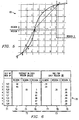
- FIGURE 2 illustrates region grid 60 overlaying a map generated in one embodiment of the invention.
- the map shows three taxing regions defined as region 1, region 2, and region 3.
- the regions may be representative of countries, regions, states, counties, districts, cities, or any other region for which it is desirable to determine a tax based on distance traveled in the region.
- Each taxing region may have a different tax structure and/or rate. For example, region 1 may assess tax at a first rate, whereas region 2 may assess tax at a second rate.
- Several routes throughout the regions are defined in part by points A, B, C, D, E, F, G, and H. These points may represent cities, boundaries between regions, or any other landmark or geographic location that may define a route. For example, points A, B, E, F, G, and H represent cities within a particular region. Points C and D represent points on the border between two regions.
- Region grid 60 disclosed in FIGURE 2 comprises a plurality of cells. Each cell is associated with the taxing region (either region 1, 2 or 3) within which it is located. All cells are approximately equal in size. Preferably, a cell would be located wholly in one region or another. In some cases, however, such as when the boundaries between regions are not straight lines, a cell may be partially located in a plurality of regions. In this latter case, the cell may be associated with the region in which most of the cell is located. Software may be used to fill in the data associated with each cell of region grid 60. This data may include the region associated with the cell, geographical coordinates defining the cell, or routes traveling over the area represented by the cell.
- the area represented by the cells is configurable. That is, the cells may represent one square mile parcels, five square mile parcels, ten square mile parcels, or other predefined areas.
- the cells may be squares, rectangles, circles, polygons, or any other geometric construct that facilitates the definition of a region.
- the area represented by the cells determines the accuracy of the tax determination. For instance, suppose that a cell is partially located in several regions. The cell is associated with a single taxing region. If the area represented by the cell is one square mile, the error generated by associating a single region with the cell would be less than if the area represented by the cell is ten square miles.
- FIGURE 3 illustrates an enlarged portion of region grid 60 disclosed in FIGURE 2.
- FIGURE 3 shows route B-C-D over which vehicle 20 travels.
- mobile unit 22 obtains position fixes for vehicle 20 at points o, p, q, r, s, and t.
- Mobile unit 22 on vehicle 20 establishes a plurality of position fixes o, p, q, r, s, and t using position system 50 or an on-board positioning sensor.
- Processor 100 which is part of mobile unit 22, determines a route traveled by vehicle 20 in response to the position fixes o, p, q, r, s, and t.
- the route of vehicle 20 is represented by lines o-p, p-q, q-r, r-s, and s-t connecting position fixes o, p, q, r, s, and t.
- Processor 100 then divides each line into a plurality of segments.
- the end point of each segment shown as the dots on lines o-p, p-q, q-r, r-s, and s-t, defines a vehicle position along the route of vehicle 20.
- mobile unit 22 can generate several vehicle positions for each position fix provided by positioning system 50 or an on-board positioning sensor.
- each segment may be proportioned to the size of the cells in region grid 60. As discussed above, if frequent position fixes are taken, there may be no need to interpolate between the position fixes to generate additional vehicle positions. With or without interpolation, the spacing between position fixes (or vehicle positions if interpolation is used) should be coincident with the cell size, so that a transition from one cell to an adjacent cell will be detected. It should be understood that any reference to vehicle positions includes interpolated vehicle positions, position fixes, or both.
- Processor 100 references a map overlaid with a plurality of cells, shown generally by grid 60 in FIGURE 2 and in detail in FIGURE 3.
- the map and associated grid may be generated by processor 100, but is normally produced by another computer or person and loaded into mobile unit 22 for use by processor 100.
- Each cell is associated with a taxing region 1, 2, or 3.
- One or more vehicle positions may be contained within a single cell.
- Processor 100 identifies the cell containing the vehicle position. Processor 100 then associates the vehicle position with the taxing region associated with the cell.
- Processor 100 determines the distance traveled in each taxing region in response to the vehicle positions associated with that taxing region.
- Processor 100 can determine distance by reading odometer 109 (FIGURE 9) at each position fix.
- Another way in which processor 100 can determine distance is by summing up the number of segments within a taxing region and multiplying that figure by the distance represented by each segment. For example, if vehicle 20 has traveled 24 segments in a taxing region and each segment represents 10 miles, then processor 100 calculates that vehicle 20 has traveled 240 (24 X 10) miles in the region.
- processor 100 can determine distance for vehicle 20 is by calculating the distance of each segment using standard geometrical formulae and then summing up these distances. For example, if vehicle 20 has traveled segments of 10 miles, 12 miles, and 9 miles in a taxing region, then processor 100 calculates that vehicle 20 has traveled 31 (10 + 12 + 9) miles within that region. A calculation based on straight line segments may not accurately represent curvature of the road. Therefore, distance can be adjusted by multiplying the sum of the straight line segments by a curvature factor (i.e. 1.1), which represents an estimate of the increase in distance due to road curvature. Different curvature factors for different roads may be used by mobile unit 22.
- a curvature factor i.e. 1.1
- Processor 100 determines a tax in the region in response to the computed distance traveled by vehicle 20 in the region.
- Mobile unit 22 may then transmit the determined distance and tax to a remote location, such as dispatch 30.
- FIGURES 4-6 An alternative embodiment of the invention is disclosed in FIGURES 4-6. Whereas the first method disclosed in FIGURES 2 and 3 focuses upon taxing regions, the second method disclosed in FIGURES 4-6 focuses upon predetermined vehicle positions which correspond to distinct geographic landmarks or monuments, such as cities, intersections between routes, or intersections of routes with regional boundaries.
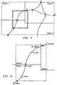
- FIGURE 4 illustrates vehicle position grid 65 overlaying a map. Similar to FIGURE 2, the map in FIGURE 4 is divided into taxing regions 1, 2, and 3. Several routes throughout the regions are defined in part by points A, B, C, D, E, F, G and H. As discussed above, these points may represent cities, boundaries between regions, or any other landmark or geographic location that may define a route. These points are associated with predetermined vehicle positions.
- Vehicle position grid 65 comprises a plurality of cells, which can be approximately equal in size. Normally, vehicle position grid 65 is based on an approved mileage database, such as those provided by Rand-McNally, ALK, and others.
- the cells in vehicle position grid 65 are associated with the predetermined vehicle positions corresponding to points along the route traveled by vehicle 20. That is, the cells contain A, B, C, D, E, F, G, or H associated with the predetermined vehicle position to which it is most closely located. In some instances, however, one part of the cell may be more closely located to one predetermined vehicle position whereas another part of the cell may be more closely located to another predetermined vehicle position. In such a case, the cell is associated with the predetermined vehicle position to which most of the cell is more closely located. Software may be used to fill in the data contained within each cell. For example, vehicle position grid 65 may be completed by a program using a spiraling or an expanding radius technique originating at each predetermined vehicle position to fill the cells. Some outlying cells are not associated with any predetermined vehicle positions.
- the number of predetermined vehicle positions contained in vehicle position grid 65 dictates the accuracy of the distance and tax determinations for this method. That is, if more predetermined vehicle positions are used, accuracy will be increased. For example, suppose vehicle 20 travels from Dallas to Los Angeles. Further suppose that vehicle position grid 65 only has Dallas, Los Angeles, and Phoenix as predetermined vehicle positions. As will be discussed below, for any two predetermined vehicle positions of vehicle position grid 65, there will be corresponding distances and taxes. Vehicle 20, however, may travel to Los Angeles from Dallas via Phoenix along at least two different routes, one of which is longer than the other. One route takes vehicle 20 through Amarillo, whereas another route takes vehicle 20 through El Paso. The route through Amarillo is longer.
- a complete trip of vehicle 20 from Dallas to Los Angeles may include small distances at the beginning and end of the trip that can be added to the total distance traveled. For example, if the trip begins in Fort Worth (approximately thirty-five miles from Dallas), but the first predetermined vehicle position is Dallas, then mobile unit 22 should add the additional thirty-five miles traveled between Fort Worth and Dallas to the calculation. Similarly, if Los Angeles is the last predetermined vehicle position on the trip, but vehicle 20 continues a short way to its destination in Pasadena, then this distance should be added to the calculation. An additional calculation may also be needed when vehicle 20 travels into outlying cells of vehicle position grid 65 that are not associated with any predetermined vehicle positions. In this situation, mobile unit 22 can adopt a hybrid technique that uses the other methods described to compute distance and tax determinations when vehicle 20 travels into outlying cells.
- FIGURE 5 illustrates an enlarged portion of vehicle position grid 65 disclosed in FIGURE 4.
- FIGURE 5 illustrates route B-C-D traveled by vehicle 20 in taxing regions 1 and 2.
- mobile unit 22 takes position fixes o, p, q, r, s, and t for vehicle 20 using positioning system 50 or an on-board positioning sensor.
- the position fixes o, p, q, r, s, and t are then related to predetermined vehicle positions, which establishes the route B-C-D traveled by vehicle 20.
- the determination for tax in this method can use the actual distance between points B, C, and D or highway mileage derived from a mileage database. As discussed below, the operator of vehicle 20 may record the actual mileage between the predetermined vehicle positions.
- a method for determining a tax for vehicle 20 traveling through a plurality of taxing regions includes determining a plurality of vehicle positions, associating each vehicle position with a taxing region, and determining the tax in each taxing region in response to the vehicle positions associated with the taxing region.
- the step of determining a plurality of vehicle positions is performed as follows.
- Mobile unit 22 establishes a plurality of position fixes using positioning system 50 or an on-board positioning sensor. Depending on the frequency of position fixes and the cell size of grid 65, mobile unit may also generate vehicle positions between position fixes by interpolation.
- a map is generated with a plurality of cells, shown generally by vehicle position grid 65 in FIGURE 4. Taxing regions are defined on the map.
- Each cell is associated with a predetermined vehicle position.
- Processor 100 next associates each position fix with a cell in vehicle position grid 65, which identifies a predetermined vehicle position. Using the predetermined vehicle positions associated with the position fixes, processor 100 reconstructs the route traveled by vehicle 20 through vehicle positions B, C, and D.
- Processor 100 utilizes a database containing the predetermined vehicle positions, the corresponding distance in each taxing region between vehicle positions, and the tax associated with each taxing region between predetermined vehicle positions.
- Processor 100 determines the distance traveled by vehicle 20 in each taxing region by referencing the database for the distance between each predetermined vehicle position along the route traveled by vehicle 20.
- Processor 100 determines the tax in each region by referencing the database for the tax associated with each taxing region between the predetermined vehicle positions along the route traveled by vehicle 20.
- a more detailed explanation of this method is set forth in the description for FIGURE 13.
- FIGURE 6 illustrates table 70 generated in the embodiment of the invention disclosed by FIGURES 4 and 5.
- Table 70 may be referenced in order to determine distance traveled and tax of vehicle 20 between any two predetermined vehicle positions that are associated with the cells of vehicle position grid 65.
- Table 70 includes a plurality of sections.
- the first section which comprises column 71, contains a first predetermined vehicle position and a second predetermined vehicle position.
- the predetermined vehicle positions in column 71 correspond to the predetermined vehicle positions associated with the cells of vehicle position grid 65. These pairs of predetermined vehicle positions define one leg of the route traveled by vehicle 20.
- a distance section 72 contains the distance in each taxing region traveled by vehicle 20 between first and second predetermined vehicle positions.
- Distance section 72 may be further separated into region distance columns 74, 75, and 76. Each of these columns contains the distance traveled by vehicle 20 between the first and second vehicle positions within a particular taxing region. Specifically, region distance column 74 contains miles traveled in region 1, region distance column 75 contains miles traveled in region 2, and region distance column 76 contains miles traveled in region 3.
- Each leg of the route, specified in column 71 can include one or more entries in region columns 74, 75, and 76. For example, route C-D includes sixty-five miles in taxing region 2 and five miles in taxing region 3.
- a tax section 73 contains a tax for taxing regions between first and second predetermined vehicle positions. Tax section 73 may be further divided into region tax columns 77, 78, and 79. Each of these columns contains a tax for vehicle 20 between first and second predetermined vehicle positions for a particular taxing region. Region tax column 77 contains the dollar amount of tax for region 1, region tax column 78 contains the dollar amount of tax for region 2, and region tax column 79 contains the dollar amount of tax for region 3. These taxes may be based on a tax rate per miles traveled, a flat tax for a predefined range of miles traveled, fees for traveling over particular roads or bridges, or any other tax computation based on the route of vehicle 20.
- Processor 100 references table 70 after processor 100 has determined that vehicle 20 has traveled between two predetermined vehicle positions. For example, referring to FIGURE 5, after processor 100 has determined that vehicle 20 has passed through point D along route B-C-D, processor 100 references line 3 in table 70 which corresponds to route C-D. By referencing distance section 72, processor 100 determines that vehicle 20 traveled 65 miles within region 2 between points C and D. By referencing tax section 73, processor 100 determines that vehicle 20 incurred $.30 of tax in region 2 and $.02 of tax in region 3 while traveling along route C-D. This information may then be displayed on output device 104 (FIGURE 8) of mobile unit 22 or input/output device 126 (FIGURE 10) at dispatch 30.
- output device 104 FIGURE 8 of mobile unit 22 or input/output device 126 (FIGURE 10) at dispatch 30.
- FIGURES 7 and 8 Another embodiment of the invention is disclosed in FIGURES 7 and 8. Unlike the first method disclosed in FIGURES 2 and 3 and the second method disclosed in FIGURES 4-6, the third method disclosed in FIGURES 7 and 8 does not use a grid pattern. Rather, this method uses odometer 109 in conjunction with a geographical database to determine distance traveled by and tax for vehicle 20.
- FIGURE 7 illustrates a map showing the operation of this embodiment of the invention. The map is divided into taxing regions 1, 2, and 3. A plurality of routes through the regions are defined in part by points A, B, C, D, E, F, G, and H. Again, these points may represent any landmark or geographic location that may define a route, such as a city, a boundary between regions, an intersection of a route with a boundary, or an intersection of two or more routes.
- the geographical database contains information defining a plurality of taxing regions.
- This geographic information may include coordinates defining regional boundaries, the intersections of routes with regional boundaries, or any other information that allows a processor to determine that vehicle 20 has traveled from one region into another.
- the geographical database may include a pair of latitude-longitude coordinates which represent the endpoints of a line corresponding to the boundary between taxing region 1 and taxing region 2.
- the geographical database can define a set of polygons or other geometrical constructs that define the taxing region.
- the geographical database may also comprise line segments, splines, or curves that define the boundary between taxing regions. Using any definition of taxing region boundaries or area, processor 100 can determine that vehicle 20 has moved from one region into an adjacent region.
- FIGURE 8 illustrates an enlarged portion of the map shown in FIGURE 7.
- FIGURE 8 illustrates route B-C-D traveled by vehicle 20 in taxing regions 1 and 2.
- Mobile unit 22 takes position fixes o, p, q, r, s, and t for vehicle 20 using either positioning system 50 or an on-board positioning sensor. The position fixes o, p, q, r, s, and t are then related to a taxing region.
- Mobile unit 22 records the reading of odometer 109 at each of the position fixes o, p, q, r, s and t, as shown in the mileage readings in FIGURE 8. The determination of tax in this third method is based upon the actual distance measured by odometer 109 between position fixes.
- a method for determining a tax for vehicle 20 traveling through a plurality of taxing regions includes determining a plurality of vehicle positions, associating each vehicle position with a taxing region, and determining the tax in each taxing region in response to the vehicle positions associated with the taxing region.
- Mobile unit 22 establishes a plurality of position fixes using positioning system 50 or an on-board positioning sensor.
- Each position fix may be in the form of standard geographical coordinates such as latitude and longitude.
- the step of associating each vehicle position with a taxing region is performed as follows.
- Mobile unit 22 accesses a database that contains information defining a plurality of taxing regions and may comprise coordinates defining regional boundaries, intersections of routes with regional boundaries, or any other information that allows a processor to determine that vehicle 20 has traveled from one taxing region into another.
- Mobile unit 22 then associates each position fix with a taxing region in response to the geographical information contained in the database.
- the step of determining the tax for vehicle 20 is executed as follows.
- Mobile unit 22 measures the distance traveled by vehicle 20 between position fixes using odometer 109.
- odometer 109 may be the odometer included in vehicle 20. or a separate odometer.
- Processor 100 determines the distance traveled in each taxing region in response to the position fixes associated with that taxing region and the distance measured by odometer 109.
- the present invention contemplates that processor 100 may determine distance using one of two alternative methods at this step.
- Processor 100 determines the amount of mileage recorded by odometer 109 since the last position fix and adds this amount to the distance already recorded for the region. For example, assume vehicle 20 has traveled twenty miles since the last position fix and entered a new taxing region at the second mile. Normally, processor 100 credits twenty miles to the old taxing region. To further refine the distance determination, processor 100 may use the position fix, information contained in the geographical database, and standard geometric equations to calculate approximately at what mileage since the last odometer reading vehicle 20 passed into the new taxing region. Processor 100 then credits a proportionate amount of mileage to the old taxing region and the new taxing region. Processor 100 then adds two miles to the distance traveled in the old region and eighteen miles to the distance traveled in the new region. Processor 100 then determines a tax for each taxing region in response to the distance traveled by vehicle 20 in that taxing region. A more detailed explanation of this third method is set forth in the description for FIGURE 14.
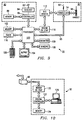
- FIGURE 9 is a schematic representation of mobile unit 22.
- Mobile unit 22 includes mobile positioning receiver 80, mobile communications device 90, odometer 109, and other associated hardware and software, described below.
- Mobile positioning receiver 80 includes antenna 82, receiver 84, controller 86, and memory 88.
- mobile positioning receiver 80 receives positioning information from satellites 52 over positioning information streams 54 at antenna 82.
- Receiver 84 processes the positioning information to extract ephemeris, almanac, and clock correction data.
- Controller 86 receives the positioning information and computes a position fix. These determinations performed by controller 86 may use data stored in memory 88.
- Mobile communications device 90 includes an antenna 92, transceiver 94, and a handset 96. In operation, mobile communications device 90 transmits vehicle information over vehicle information stream 48. The vehicle information may be received by dispatch 30 using elements of communications link 40, such as receiver site 44 associated with the cellular telephone network. Mobile communications device 90 can also receive data or calls transmitted to mobile unit 22 from a remote site, such as dispatch 30. Handset 96 provides traditional voice or data communications using mobile communications device 90.
- Odometer 109 may be the odometer originally included with vehicle 20 or a second odometer that is more integral to mobile unit 22. Odometer 109 measures the actual distance traveled by vehicle 20. An important technical advantage of the present invention is provided by odometer 109 because many taxing authorities currently accept odometer readings as an accurate measurement of distance traveled by a vehicle. The accuracy of the tax determination will depend in part upon the accuracy of odometer 109.
- Processor 100 manages the communicating, calculating, locating, and reporting features of mobile unit 22.
- processor 100 receives a position fix from controller 86 and a measured distance from odometer 109.
- Processor 100 then generates vehicle information. Determination of tax for vehicle 20 may be performed by processor 100, by central controller 122 at dispatch 30, or by a combination of processor 100 and central controller 122.
- Processor 100 routes the vehicle information or determined tax through link 95 or over any other appropriate path, such as through modem or dual tone multifrequency (DTMF) coder/decoder 110 and bus drivers 112 to transceiver 94 of mobile communications device 90.
- Transceiver 94 then transmits the vehicle information or determined tax to dispatch 30 over communications link 40.
- DTMF dual tone multifrequency
- memory 102 may contain grids, such as region grid 60 or vehicle position grid 65, programs, maps, geographical databases, and other information required by processor 100 to perform its functions.
- Memory 102 may be random access memory (RAM), read-only memory (ROM), magnetic media, CD-ROM, removable memory devices, or any other device that allows storage or retrieval of data.
- Processor 100 and controller 86, as well as memory 102 and memory 88, may be separate or integral components of mobile unit 22.
- Mobile unit 22 contemplates any arrangement, processing capability, or task assignment between mobile positioning receiver 80, mobile communications device 90, and processor 100.
- Vehicle information or determined tax may be sent to output device 104 to generate a map displaying vehicle 20 and the position fixes.
- Output device 104 can produce audible information, such as the announcement of a determined tax and distance traveled in a taxing region to the operator of vehicle 20.
- Processor 100 is also coupled to input device 106, which may be a keypad or touch screen, as well as voice recognition software and hardware that can accept audible commands and information.
- input device 106 may be a keypad or touch screen, as well as voice recognition software and hardware that can accept audible commands and information.
- output device 104 and input device 106 may include fixed or removable storage media, such as magnetic computer discs, CD-ROM, or other suitable media to both receive output from and provide input to processor 100 or memory 102.
- the operator of vehicle 20 may input information into mobile unit 22 when vehicle 20 reaches a significant vehicle position, such as the boundary of a taxing region.
- the operator logs information about the vehicle position based upon the position fix for vehicle 20 determined by mobile positioning receiver 80, actual time and mileage at which vehicle 20 travels from one taxing region into another, the actual route over which vehicle 20 travels, points through which vehicle 20 passes, and any other item for which it is desirable to have a record.
- the operator may manually or orally log all of this information into mobile unit 22, or the operator may cooperate with processor 100 to log the information. For instance, using input device 106, the operator may manually or orally record the moment when vehicle 20 reaches a certain geographic mark, after which processor 100 automatically logs the other items.
- the geographic mark may be one of the predetermined vehicle positions discussed above in regard to vehicle position grid 65.
- This predetermined vehicle position may be stored in memory 102 along with the other information.
- the actual highway mileage between predetermined vehicle positions, that may be included in the stored information, can later be retrieved and used to update existing databases, such as table 70.
- mobile unit 22 or dispatch 30 can then use the information to more accurately determine distance traveled by vehicle 20 between predetermined vehicle positions and the corresponding tax.
- This information allows the geographic database to be updated "on the fly" as vehicle 20 generates more accurate geographic information.
- Processor 100 generates vehicle information for transmission to dispatch 30 using mobile communications device 90.
- the vehicle information may include position fixes, vehicle positions, actual time and mileage at which vehicle 20 travels from one taxing region into another, the actual route over which vehicle 20 travels, points through which vehicle 20 passes, the determined distance and tax in a taxing region, the time of reporting, or information input by the vehicle operator, as well as any other information collected by processor 100 from various sensors 108.
- sensors 108 may include various engine sensors, truck trailer sensors, security monitors, or other devices generating information on the status or condition of mobile unit 22, vehicle 20, or its operator.
- sensors 108 can be on-board positioning sensors to determine position fixes, alone or in combination with positioning system 50.
- the generation and transmission of this vehicle information may be based on a determination that vehicle 20 has passed a significant geographic point, an elapsed time, a predetermined time, movement of mobile unit 22, sensor readings, or any other piece of information that may necessitate reporting to a remote location.
- the vehicle information is sent from processor 100 through modem or DTMF coder/decoder 110 to bus drivers 112, and then to transceiver 94 for transmission over antenna 92 to a remote location, such as dispatch 30 (FIGURE 10). Vehicle information may also be sent directly to transceiver 94 over link 95.
- Mobile unit 22 may also include a clock 116 coupled to processor 100 that may be used to synchronize the position fix received from controller 86 with vehicle information transmitted to transceiver 94.
- Mobile unit 22 shown in FIGURE 9 may be packaged into one or more housings.
- Mobile unit 22 may be mounted to vehicle 20 or an object to be tracked.
- Mobile unit 22 may also be packaged as a portable, hand-held device that provides personal timing, locating, communicating, and reporting functions.
- FIGURE 10 is a schematic representation of dispatch 30.
- Dispatch 30 includes modem or DTMF coder/decoder 120, central controller 122, a memory 124, input/output device 126, and other associated hardware and software.
- Memory 124 may be RAM, ROM, CD-ROM, removable memory devices, or any other device that allows storage or retrieval of data.
- Input/output device 126 includes any variety of output devices, such as a display, a speaker to provide audible information, removable storage media, or any other appropriate output device.
- Input/output device 126 may also include a variety of input devices, such as a keyboard, mouse, touch screen, removable storage media, or any other appropriate input device.
- determination of distance and tax for vehicle 20 may be performed wholly on vehicle 20 by mobile unit 22 or partly on vehicle 20 by mobile unit 22 and partly at dispatch 30 by central controller 122. If determinations of distance and tax are performed by mobile unit 22, dispatch 30 receives the determined distance, tax, or both for vehicle 20 in a taxing region from communications link 40.
- dispatch 30 receives vehicle information for one or more vehicles 20 carrying mobile units 22.
- vehicle information is received at central controller 122 through modem or DTMF coder/decoder 120 from communications link 40.
- reception of vehicle information at dispatch 30 may not require a data encoder.
- the vehicle information may include position fixes, vehicle positions, corresponding times for each vehicle position, measured distance, actual time and mileage at which vehicle 20 travels from one taxing region into another, route of vehicle 20, operating parameters, and other information.
- Central controller 122 processes the vehicle information to determine the distance traveled by vehicle 20 in each taxing region and the corresponding tax.
- the vehicle positions, the determined tax, and the determined distance for each taxing region may be stored in memory 124 and displayed on input/output device 126.
- Memory 124 may also contain grids, such as region grid 60 or vehicle position grid 65, programs, maps, geographical databases, and other information required by central controller 122 to perform its functions.
- Central controller 122 may also receive other information from mobile unit 22 and process this information to determine expected time of arrival, locate, track, dispatch, and communicate with mobile unit 22.
- central controller 72 can maintain a database in memory 124 of all mobile units 22 with their current expected times of arrival, location, status, and relevant sensor readings. This database can also be used to initiate communication with mobile unit 22.
- central controller 122 may perform a call delivery function that routes incoming calls to mobile unit 22 through communications link 40.
- FIGURE 11 is a flow chart of a method for determining tax using region grid 60 shown in FIGURES 2 and 3. The following explanation of the method illustrated in FIGURE 11 assumes that all steps are performed on vehicle 20.
- processor 100 of mobile unit 22, some other on-board or remote device, or a person generates region grid 60 (at 210), comprising a plurality of cells, each cell associated with a taxing region.
- the taxing regions may represent countries, states, counties, districts, cities, or any other region for which it is desirable to determine a tax.
- Processor 100 next initializes the region, distance traveled by vehicle 20 in the region, and tax for the region (at 212).
- Receiver 84 of mobile positioning receiver 80 processes positioning information received from satellites 52, and controller 86 determines a position fix.
- an on-board positioning sensor establishes a position fix.
- Processor 100 receives the position fix, from either mobile positioning receiver 80 or the on-board positioning sensor, defining a leg of the route traveled by vehicle 20.
- Processor 100 determines an initial vehicle position representing the beginning of the leg defined by the position fixes (at 214). Based upon the information contained in region grid 60 and other information that may be contained within memory 102, processor 100 relates the vehicle position to a region (at 216).
- Processor 100 determines (at 218) whether the region is the same as before. If the region is not the same as before, processor 100 determines the tax for the old region (at 220). Processor 100 stores (at 222) the old region, distance traveled in that region, and the determined tax for the region within memory 102. Processor 100 sets the region to the new region (at 224). Processor 100 initializes the distance and tax for the new region (at 226). Processor 100 increments the distance in the current region (at 228). The step of incrementing the distance may be performed using vehicle positions or by reading mileage from odometer 109. If the region is the same, processor 100 skips to the step of incrementing distance in the current region (at 228). Mobile unit 22 then returns to the step of determining a vehicle position (at 214).
- FIGURE 12 is a flow chart of an alternative method for determining tax using region grid 60 shown in FIGURES 2 and 3.
- This method segments each leg of the route defined by position fixes into numerous vehicle positions. Again, this method may be performed by mobile unit 22, dispatch 30, or a combination of mobile unit 22 and dispatch 30. The segmentation of position fixes into numerous vehicle positions may be performed after mobile unit 22 has collected a number of position fixes. Therefore, the method described with reference to FIGURE 12 may be more effectively performed at dispatch 30 or host 35, where more processing capability and data storage is available. However, to promote clarity in description among the different methods, the following explanation assumes that all steps are performed by mobile unit 22 on vehicle 20.
- processor 100 of mobile unit 22 generates region grid 60 (at 310) comprising a plurality of cells, each cell associated with a taxing region.
- Processor 100 initializes the region, the distance traveled by vehicle 20 in the region, and the tax for the region (at 312).
- Processor 100 sets a new position fix to an old position fix (at 313).
- Receiver 84 of mobile positioning receiver 80 processes positioning information received from satellites 52, and controller 86 determines a new position fix (at 314).
- an on-board positioning sensor establishes a new position fix.
- Processor 100 receives the new position fix from either mobile positioning receiver 80 or the on-board positioning sensor. Based upon this information and other information that may be contained within memory 102, processor 100 determines a route between the old position fix and the new position fix (at 316). Processor 100 specifies a sequence of vehicle positions along the route (at 318). These vehicle positions can be spaced at equal distances along the route.
- Processor 100 increments to the next vehicle position along the route toward the new position fix (at 320). Based upon the information contained in region grid 60, processor 100 relates the vehicle position to a taxing region (at 322). Processor 100 then increments distance (at 324) within the current region. The step of incrementing the distance may be performed using vehicle positions or by reading mileage from odometer 109.
- Processor 100 next determines (at 328) whether the region is the same as before. If the region is not the same, processor 100 determines the tax for the old region (at 326) and stores the old region, the distance traveled by vehicle 20 in that region, and the determined tax for that region (at 330). Processor 100 initializes the distance and tax (at 332) and sets the region to the new region (at 334).
- processor 100 skips the steps of storing (330), initializing (332), and setting (334) and determines (at 336) whether the vehicle positions have reached the new position fix. If the vehicle positions have reached the new position fix, mobile unit 22 returns to the step of determining a new position fix. If the vehicle positions have not reached the new position fix, mobile unit 22 returns to the step of incrementing vehicle positions along the route toward the new position fix.
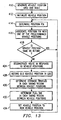
- FIGURE 13 is a flow chart of a method for determining tax for vehicle 20 using vehicle position grid 65 shown in FIGURES 4 and 5. The following explanation of the method illustrated in FIGURE 13 assumes that all steps are performed on vehicle 20.
- processor 100 at mobile unit 22 generates vehicle position grid 65 and table 70 (at 410).
- Vehicle position grid 65 comprises a plurality of cells, each cell associated with a predetermined vehicle position. Several cells may contain the same predetermined vehicle position.
- Table 70 contains information about the distance and the tax for each region between different predetermined vehicle positions.
- Processor 100 then initializes the vehicle position (at 412).
- Receiver 84 of mobile positioning receiver 80 processes positioning information received from satellites 52. Controller 86 determines a position fix (at 414). In the alternative, an on-board positioning sensor establishes a position fix. Processor 100 receives the position fix from either mobile positioning receiver 80 or the on-board position sensor. Based upon the information contained in vehicle position grid 65, processor 100 associates the position fix with one of the predetermined vehicle positions (at 416).
- Processor 100 next determines (at 418) whether the vehicle position is the same as before. If the vehicle position is the same as before, mobile unit 22 returns to the step of determining the position fix (at 414). Processor 100 reconstructs (at 424) a route traveled by vehicle 20 in response to the vehicle positions. Processor 100 records the old vehicle position in memory 102 or output device 104 (at 428). By referencing table 70, processor 100 determines the distance traveled by vehicle 20 in each taxing region between the vehicle positions (at 430). Processor 100 may also augment or supplement the distance determination by reading mileage from odometer 109. Next, processor 100 determines the tax in each taxing region between vehicle positions by referencing table 70 (at 432). Processor 100 then sets the vehicle position to the new vehicle position (at 434). Mobile unit 22 returns to the step of determining a position fix (at 414).
- FIGURE 14 is a flow chart for the third method for determining tax of a vehicle as shown in operation using the map illustrated in FIGURES 7 and 8.
- processor 100 generates a geographical database (at 510).
- the geographical database comprises information that allows processor 100 to determine at what point vehicle 20 traveled from one taxing region into another, such as geographical coordinates defining regional boundaries or the intersections of routes with regional boundaries.
- Processor 100 then initializes the distance by recording the reading on odometer 109, and the vehicle position (at 512).
- Receiver 84 of mobile positioning receiver 80 processes positioning information received from satellites 52. Controller 86 determines a position fix (at 514). Alternatively, an on-board positioning sensor establishes a position fix. Processor 100 receives the position fix from either mobile positioning receiver 80 or the on-board positioning sensor. Based upon the position fix and information contained within the geographical database, processor 100 determines the taxing region in which vehicle 20 is located (at 516). Processor 100 reads odometer 109 (at 517) to obtain a measured distance.
- Processor 100 determines (at 518) whether the region is the same as before. If the region is not the same, processor 100 updates the distance in the old region (at 520) based upon the distance measured by odometer 109 and the information contained in the geographical database. As discussed above, processor 100 may either credit all the distance to the old region or credit a proportionate amount of the distance to each of the old region and the new region. Processor 100 then determines the tax for the old region (at 522) based upon the distance traveled in the old region. Processor 100 stores the old region, the distance traveled by vehicle 20 in that region, and the determined tax for the region (at 524). Processor 100 initializes the distance (at 526) and updates the region to the new region (at 528).
- processor 100 skips the steps of updating in the old region (520), determining tax (522), storing (524), initializing (526), and updating the region (528).
- Processor 100 then updates the distance traveled in the current region using the distance measured by odometer 109, the position fix, and the information contained in the geographical database (at 530).
Abstract
Description
- This invention relates to determining tax of a vehicle, and more particularly to a system for determining tax of a vehicle using a positioning system.
- Mobile positioning technology has advanced substantially over the past decade. Many cars, trucks, airplanes, boats, and other vehicles are equipped with devices that provide convenient and reliable mobile positioning using either networks of satellite-based and land-based transceivers or an on-board positioning sensor, such as an inertial navigation system or a dead reckoning system.
- Many users of mobile positioning systems, particularly those operating commercial vehicles, also require an accurate determination of tax assessed by one or more taxing regions through which the vehicles travel. Previously, tax determinations were based upon manual reporting and charting of vehicle positions, or recreation of the miles traveled in taxing regions after a trip. For example, one way to determine tax for a vehicle is to estimate the number of miles traveled by the vehicle based upon a corresponding distance taken along a preferred route on a map. This approach, however, may not be suitable for particular applications that require more accuracy in the determination of tax. Consequently, a need has arisen for an apparatus and method that accurately determines tax of a vehicle. Furthermore, operators of commercial vehicles may also require a way of reporting this tax to a remote location. For example, a cellular telephone in a vehicle offers a convenient communications link to report a determined tax.
- In accordance with the present invention, the disadvantages and problems associated with previous techniques used to determine tax for a vehicle have been substantially reduced or eliminated. One aspect of the present invention provides a system for determining a tax of a vehicle using positioning technology.
- According to an embodiment of the present invention, an apparatus on a vehicle for determining a tax for the vehicle includes a positioning device. The positioning device determines a plurality of vehicle positions along a route traveled by the vehicle. A memory stores geographic information defining a plurality of regions. A processor is coupled to the positioning device and the memory. The processor receives vehicle positions from the positioning device and geographic information from the memory. The processor determines the distance traveled by the vehicle in the regions in response to the vehicle positions and the geographic information.
- According to another embodiment of the present invention, a method for determining a tax for a vehicle traveling through a plurality of taxing regions includes determining a plurality of vehicle positions. Each vehicle position is associated with a taxing region. The tax in each taxing region is determined in response to the vehicle positions associated with that taxing region.
- Important technical features of the present invention include improving the accuracy of determining the distance traveled or tax for a vehicle passing through regions using a positioning system. The present invention provides determination of the tax on the vehicle or transmission of vehicle position information for determination at a remote location. Other important technical advantages include reporting tax information to a central location using a wireless communications network, such as the cellular telephone network. Another important technical advantage of the present invention includes consolidating tax determinations with the generation of billing information. Further technical advantages include determining tax of a vehicle based upon actual miles traveled by the vehicle. Yet another important technical feature of the present invention includes taking into consideration any deviation from a predetermined route when determining distance and tax. Another important technical advantage of the invention includes reducing the human error associated with determining distance traveled or tax. Other technical advantages are readily apparent to one skilled in the art from the following figures, description, and claims.
- For a more complete understanding of the present invention and for further features and advantages, reference is now made to the following description taken in conjunction with the accompanying drawings, wherein like reference numerals represent like parts, in which:
- FIGURE 1 illustrates a system for determining and reporting a tax of a vehicle;
- FIGURE 2 illustrates a grid overlaying a map generated in a first embodiment of the invention;
- FIGURE 3 illustrates an enlarged portion of the grid shown in FIGURE 2;
- FIGURE 4 illustrates a grid overlaying a map generated in a second embodiment of the invention;
- FIGURE 5 illustrates an enlarged portion of the grid shown in FIGURE 4;
- FIGURE 6 illustrates a table generated in the second embodiment of the invention;
- FIGURE 7 illustrates a map showing the operation of a third embodiment of the invention;
- FIGURE 8 illustrates an enlarged portion of the map shown in FIGURE 7;
- FIGURE 9 is a schematic representation of a mobile unit;
- FIGURE 10 is a schematic representation of a dispatch;
- FIGURE 11 is a flow chart of the first method for determining tax of a vehicle, using the grid shown in FIGURES 2 and 3;
- FIGURE 12 is an alternative flow chart of the first method for determining tax of a vehicle, using the grid shown in FIGURES 2 and 3;
- FIGURE 13 is a flow chart of the second method for determining tax of a vehicle, using the grid shown in FIGURES 4 and 5; and
- FIGURE 14 is a flow chart of the third method for determining tax of a vehicle, as shown in operation using the map of FIGURES 7 and 8.
- FIGURE 1 illustrates a
system 10 for determining the tax of avehicle 20 traveling from a point of origin X (located in a taxing region 1) to a destination Y (located in a taxing region 2) across a regional boundary 1-2.System 10 includesvehicle 20 equipped with amobile unit 22, adispatch 30, and acommunications link 40.System 10 provides an accurate determination of tax forvehicle 20 traveling along route X-Y for each oftaxing regions System 10 may also be used to determine thedistance vehicle 20 travels in different regions, without calculating any associated tax. Therefore, all discussions below that relate to determining a tax forvehicle 20 apply equally to determining thedistance vehicle 20 travels in any geographic regions for reasons other than tax computation. - FIGURE 1 shows
mobile unit 22 onvehicle 20. The present invention contemplatesmobile unit 22 being carried by all types of vehicles, including cars, trucks, airplanes, barges, boats, railcars, truck-trailers, or any other moveable object for which it is desirable to determine a tax based upon distance traveled within a taxing region. The taxing regions may be countries, regions, districts, states, counties, cities, particular roads or any other region that may charge a tax based on fuel consumption, road usage, or other activity relating to distance traveled or roads traveled along in the region. Each taxing region may have its own tax structure. Thus, the tax rate inregion 1 may differ from the tax rate inregion 2. Furthermore, each region may contain toll and non-toll road designations, which may also impact the determination of tax. -
Mobile unit 22 comprises an odometer 109 (FIGURE 9) operable to measure the distance traveled byvehicle 20. Odometer 109 can be the odometer originally included invehicle 20. Alternatively,odometer 109 can be an odometer that is more integral tomobile unit 22 thanvehicle 20. In one embodiment of the present invention, as will be discussed below in more detail,odometer 109 provides distance information that is used bymobile unit 22 to determine tax forvehicle 20. Odometer 109 is an important technical aspect of the present invention because many taxing authorities currently accept odometer readings as an accurate measurement of distance traveled by a vehicle. Alternatively,mobile unit 22 may use an approved mileage database, such as those provided by Rand-McNally and others, to determine distance traveled. - Using a
positioning system 50,mobile unit 22 determines the position ofvehicle 20. Specifically,mobile unit 22 comprises a mobile positioning receiver 80 (FIGURE 9) operable to receive positioning information frompositioning system 50.Mobile unit 22 receives positioning information over positioning information streams 54 from a plurality ofsatellites 52.Mobile unit 22 then determines its position fix using information from positioning information streams 54. The positioning information comprises accurate satellite positioning information transmitted bysatellites 52 and pseudorange data represented by the time of arrival of positioning information streams 54 atmobile unit 22. -
Positioning system 50 is illustrated as a satellite-based radio navigation system, such as the NAVSTAR global positioning system (GPS). The description uses the NAVSTAR GPS as arepresentative positioning system 50, but any land-based or satellite-based system may be used. For example,positioning system 50 may be a land-based LORAN-C, a space-based GLONASS, or any other appropriate positioning technology. As shown in FIGURE 1,positioning system 50 comprises a plurality ofsatellites 52. In general,positioning system 50 comprises a plurality of space-based or land-based transmitters that emit positioning information. -
Satellites 52 maintain accurate and synchronized time and simultaneously transmit positioning information that contains satellite specific and system information required bymobile unit 22 to determine the position fix ofvehicle 20. The positioning information transmitted bysatellites 52 may include high precision clock and ephemeris data for a particular satellite, low precision clock and ephemeris data for every satellite in a constellation ("almanac data"), health and configuration status for all satellites, user text messages, and other parameters describing operation ofpositioning system 50. -
Positioning system 50 may also comprise additional satellites and one or more positioning receivers. The additional satellites may also communicate positioning information tomobile unit 22. In one embodiment, apositioning receiver 46 may be mounted on areceiver site 44, that is part of communications link 40, to implement differential GPS techniques. Positioningreceiver 46 generates correction data that enablesmobile unit 22 to more accurately determine the position fix ofvehicle 20. Positioningreceiver 46 transmits the correction data tomobile unit 22 over any suitable link, such as avehicle information stream 48. - Alternatively,
mobile unit 22 can generate positioning information itself using an on-board positioning sensor. For example, an inertial navigation system onvehicle 20 integrates accelerations imparted tovehicle 20 to determine current position. As another example, a dead reckoning system computes vehicle location based on compass orientation and distance traveled at that orientation. A dead reckoning system onvehicle 20 includes a direction finder, such as a compass, integrated with a distance sensor, such asodometer 109 or a tire rotation counter, to track the location ofvehicle 20 and determine its current position. - In response to the positioning information from
positioning system 50 or an on-board positioning sensor,mobile unit 22 determines the position fixes ofvehicle 20. These position fixes may comprise standard geographical coordinates such as latitude and longitude. - The interval of time between determinations of a position fix may be configurable by either
mobile unit 22 ordispatch 30. The determinations of a position fix may also be continuous. As discussed below, this interval of time dictates the accuracy of the determinations of distance traveled and tax ofvehicle 20 in a taxing region. - The present invention contemplates that additional processing of information and determining of the distance traveled and tax in a taxing region may be performed on
vehicle 20 bymobile unit 22 or at a remote location, such asdispatch 30 or ahost 35. In one embodiment of the present invention,mobile unit 22 determines the distance traveled and tax ofvehicle 20 based upon the position fixes, the distance measured byodometer 109, or other information that may be contained withinmobile unit 22. Aftermobile unit 22 has made these determinations, this information can be transmitted to dispatch 30 orhost 35 usingcommunications link 40. - In another embodiment of the invention, dispatch 30 or
host 35 performs the determination of distance traveled and tax aftermobile unit 22 has transmitted vehicle information, including the position fixes and/or the distance measured byodometer 109, to the remote location.Mobile unit 22 thus includes a transceiver 94 (FIGURE 9) through whichmobile unit 22 transmits vehicle information to a remote location. In general,mobile unit 22 initiates transmission of information to dispatch 30 orhost 35 based on some configurable condition, such as a predetermined reporting interval, a full memory buffer, a store and forward routine, or a minimum signal strength received from communications link 40. - Communications link 40 is coupled to
mobile unit 22 onvehicle 20 and allows communication betweenmobile unit 22 and a remote location, such asdispatch 30 orhost 35. In the embodiment shown in FIGURE 1, communications link 40 comprises a cellular telephone network. More specifically, communications link 40 comprises at least onereceiver site 44 operable to receive vehicle information frommobile unit 22 and a mobile telecommunications switching office (MTSO) 42coupling receiver site 44 to dispatch 30.Mobile unit 22 determines position fixes and distances, and sends these fixes and distances along with other information toreceiver site 44 overvehicle information stream 48.MTSO 42, coupled toreceiver site 44, routes the vehicle information to dispatch 30 orhost 35. Vehicle information may be encoded using traditional data encoders, such as a modem or a dual-tone multifrequency (DTMF) coder/decoder 110 (FIGURE 9). - In other embodiments, communications link 40 may be one or a combination of dedicated telephone lines, switched telephone lines, microwave communications links, satellite-based communications links, specialized mobile radio (SMR), enhanced specialized mobile radio (ESMR), a personal communications service (PCS), a citizen's band (CB), a dedicated radio system, such as those used by police and fire fighters, or any other suitable communications link that allows
mobile unit 22 to transmit data to or receive data fromdispatch 30 orhost 35. Communications link 40 may also be an SS7 backbone link or similar network for linking land-line or cellular switches in a public switched telephone network (PSTN). Such a link allows components of the PSTN to share information for validation, roaming, billing, call routing, and other functions. Communications link 40 may also include intelligence to route information generated atmobile unit 22,dispatch 30, orhost 35 to multiple selected sites. - Furthermore,
vehicle information stream 48 may be the control channel, paging channel, part of a seized voice or data channel, or overhead message stream currently implemented in cellular telephone technology. Presently, the control channel provides paging of incoming calls, hand-off instructions, and other features of the cellular telephone network, but may be modified by one skilled in the art to include transmission of vehicle information.Vehicle information stream 48 may also be implemented using any other analog or digital communications link betweenmobile unit 22 andreceiver site 44, whether or not the communications link requires seizing of a voice or data channel, and whether or not a data encoder is used. - As
mobile unit 22 moves from one location to another, vehicle information will be transmitted todifferent receiver sites 44.Receiver sites 44 are operable to emit signals tomobile unit 22.Mobile unit 22 may then alternatively tune between several signals emitted byreceiver sites 44 to determine the strongest signal, usually relating to thenearest receiver site 44.Mobile unit 22 establishes communication with thatreceiver site 44. - Additionally, there are several developing technologies that may provide a convenient implementation of
vehicle information stream 48. For example, cellular digital packet data (CDPD) technology allows integration of data and voice using the existing cellular telephone infrastructure. In a CDPD system, digital packets of data and analog voice segments share the same channel. Other developments in digital cellular communications, such as code division multiple access (CDMA) and time division multiple access (TDMA), allow digital data and digital voice signals to be interspersed on a communications channel. These technologies integrate digital data transmission in acommunications link 40, and therefore provide a convenient implementation scheme forvehicle information stream 48. -
Mobile unit 22 may send vehicle information toreceiver site 44 in one large packet or in several smaller packets interspersed with other data used for mobile communications. For example, the vehicle information may be packaged in existing, but unused, bytes of the overhead message stream or in a dedicated protocol. One possible implementation would place vehicle information in the extended protocol described in the EIA/TIA-533 mobile communications standard, which provides for bidirectional communication betweenmobile unit 22 andreceiver site 44. - Because
dispatch 30 andhost 35 are coupled to communications link 40, dispatch 30 andhost 35 can communicate withmobile unit 22.Host 35 performs the management and control functions for one or more fleets of trucks. Therefore,system 10 may includemany hosts 35 associated with trucking companies, delivery services, or other organizations withvehicles 20 equipped withmobile units 22.Host 35 may receive vehicle information directly from communications link 40. If distance and tax forvehicles 20 have not been determined,host 35 may make these determinations. Alternatively, dispatch 30 may receive and process vehicle information from communications link 40 and then route such information to host 35. Furthermore, host 35 can transmit information tomobile unit 22 either directly using communications link 40 or indirectly throughdispatch 30. For example,host 35 may generate destination information forvehicle 20 and transmit this information over a communications link to dispatch 30. Such destination information may include one or more destinations, appointment information such as a corresponding appointment time for each destination specified, routing information, information regarding tasks to be performed at each destination specified, average travel time to each destination, rush hour and traffic information, and weather information.Dispatch 30 collects destination information fromseveral hosts 35 and transmits this information tovehicles 20. Alternatively,host 35 may transmit destination information tovehicles 20 over communications link 40. In essence, some of the functions performed bydispatch 30 may be distributed among several hosts 35. For clarity, the remainder of this description will focus primarily on the functionality ofdispatch 30, but it is understood thathost 35 can perform some or all of the functions performed bydispatch 30. -
Dispatch 30 receives the vehicle information generated bymobile unit 22 forvehicle 20 usingcommunications link 40. In particular, dispatch 30 contains a modem or DTMF coder/decoder 120 (FIGURE 10) that receives vehicle information fromMTSO 42.Dispatch 30 may comprise an input-output device 126 (FIGURE 10) operable to present visually or audibly the vehicle information atdispatch 30 once the information has been received bydispatch 30. For example, input-output device 126 displays vehicle information on a map showing thatvehicle 20 is traveling along route X-Y between point of origin X and destination Y. -
Dispatch 30 may perform additional processing of the information received frommobile unit 22 over communications link 40. As discussed above, the present invention contemplates that in some embodimentsmobile unit 22 does not perform all the determinations necessary for distance traveled and tax ofvehicle 20 in a taxing region. Thus, in some cases, in response to vehicle information, dispatch 30 determines the distance traveled by and associated tax forvehicle 20 in each taxing region through whichvehicle 20 travels. As will be explained below in more detail, dispatch 30 may determine distance traveled and tax forvehicle 20 using one of several methods. -
Dispatch 30 transfers vehicle distance, tax information, and actual payment for taxes to taxingauthority 32. Taxingauthority 32 can generate a tax bill forvehicle 20 or actually receive money and generate a receipt for taxes paid. Transfer of money directly to taxingauthority 32 can be accomplished by physically printing and mailing a check, or through any suitable electronic funds transfer technology, such as the electronic data interchange (EDI). Automatic payment of taxes to taxingauthority 32 streamlines the tax collection process, reduces potential errors and tardiness in tax computation and payment, and decreases the number of personnel required to compute and collect taxes. Whenvehicle 20 has already paid a portion of the taxes at the time of fueling or at other times, then the total taxes due taxingauthority 32 can be reduced by the amount of the prepaid taxes. Prepaid tax information can be generated atvehicle 20 either automatically or by operator intervention. -
Dispatch 30 also generates information that may be sent tovehicle 20 usingcommunications link 40. For example, one function ofdispatch 30 may be to generate destination information, as described above, forvehicle 20.Dispatch 30 can also configure the interval of time between position fix determinations bymobile unit 22. Generally, dispatch 30 may transmit tomobile unit 22 any information that facilitates the control or monitoring ofvehicle 20. - In the alternative, vehicle information may be loaded into
dispatch 30 using any suitable device, such as a keypad, a direct connection, or any suitable removable storage media. Furthermore, vehicle information may be communicated to dispatch 30 using a local wireless link. In some cases, distance traveled and tax in a taxing region do not need to be determined immediately aftervehicle 20 has reached its destination. Billing charges may be collected later. In order to avoid unnecessary telecommunications charges associated with usingtelecommunications link 40, vehicle information may be stored onvehicle 20 and later downloaded to dispatch 30 whenvehicle 20 has returned to dispatch 30. -
System 10 supports reporting of vehicle distances logged in predefined regions. When the predefined regions correspond to boundaries of taxing authorities,system 10 also provides a more accurate determination of vehicle taxes than currently available systems. It may provide these determinations near instantaneously or "on the fly." These determinations may consider the specifics of each trip, such as the route traveled byvehicle 20, actual mileage traveled within a taxing region, actual time and mileage at whichvehicle 20 traveled from one taxing region into another, and points through whichvehicle 20 passes along a particular route. In some applications, low frequency and low accuracy determinations are sufficient. Other applications, however, require greater accuracy and higher frequency determination in near real time. For example,vehicle 20 may carry packages for delivery to different stops along route X-Y. In some cases, it is desirable to bill the party receiving a package for delivery charges at the moment when the package is delivered. The present invention provides determination of the tax attributable to that delivery when the package is received. Because these determinations may be performed at fixed time intervals, on-demand, or as a result of a predetermined reporting event, billing may accurately be apportioned between deliveries. Furthermore, the present invention allows for adjustments in billing to reflect changes in tax that may be caused by additional distances traveled, such as in the case of road closures. -
System 10 supports the remote sending of vehicle information to dispatch 30 fromvehicle 20. In most cases, billing statements are generated at a central location, such asdispatch 30. The billing statements may include delivery charges. Delivery charges, in turn, take into account tax charges. Thus,system 10 provides that tax determinations may be consolidated with the generation of billing information. In this way, total taxes forvehicle 20 can be apportioned to particular deliveries, which results in more accurate billing. -
System 10 permits determination of tax forvehicle 20 based upon actual mileage driven byvehicle 20 in taxing regions. For example, referring to FIGURE 1, at themoment vehicle 20 leaves origin X to travel to destination Y, the tax forvehicle 20 would be based upon the distance traveled inregion 1 along route X-Y and the distance traveled inregion 2 along route X-Y. Suppose, however, that a severestorm forces vehicle 20 to detour from route X-Y atpoint D. Vehicle 20 must then travel through point Z in order to reach destination Y. Because the present invention determines tax based upon actual vehicle positions and distances traveled, as will be discussed in more detail below,system 20 would be able to provide an accurate tax determination even ifvehicle 20 is forced to deviate from route X-Y. -
System 10 can also adjust the tax computation based on the specific route traveled byvehicle 20. For example, a taxing region may contain both toll and non-toll roads. If the toll road is privately maintained andvehicle 20 pays the toll at the time of use, then the total distance traveled in the taxing region for purposes of tax calculation may be reduced by the distance traveled on the toll road. There may also be other adjustments to computed tax based on route, such as flat tolls for using a road or bridge. Usingsystem 10, taxingauthority 32 could easily and inexpensively account for and collect flat tolls or usage fees for roads and bridges traveled byvehicle 20. A computed tax may also depend on the route taken, whereas some roads carry a different flat tax or rate from others.System 10 can support this and other computations of tax based on the route ofvehicle 20. - Furthermore, vehicle information and tax for
vehicle 20 are automatically determined. Any human error in inputting the vehicle information or determining the tax is substantially reduced or eliminated. For example, like the present invention, some previous methods to determine tax use an odometer to measure the distance traveled by the vehicle. These methods, however, require that the operator of a vehicle record the mileage displayed on the odometer when the vehicle travels from one taxing region into another. This mileage is then used as the basis for calculating tax for the vehicle. If the operator forgets to record the mileage shown on the odometer, however, the determination of tax would be inaccurate. Because the present invention is able to determine whenvehicle 20 has traveled from one taxing region into another and to automatically record the mileage at that moment, the error associated with previous methods is eliminated. Also, since the operator ofvehicle 20 is not distracted from the primary duty of drivingvehicle 20, the risk ofvehicle 20 being involved in an accident is reduced. - In
system 10,dispatch 30 allows monitoring of at least onevehicle 20 equipped withmobile unit 22. A large company may operatedispatch 30 to monitor a plurality ofvehicles 20 equipped withmobile units 22. Smaller companies with more limited resources could pool together to either jointly operatedispatch 30 or employ an independent firm to operatedispatch 30. It should be understood that the present invention contemplates any number and arrangement ofdispatches 30 to monitor one or more fleets ofvehicles 20. - FIGURES 2-8 disclose three embodiments of the present invention. In particular, FIGURES 2 and 3 illustrate a
region grid 60 that is integral to a first method for determining the tax ofvehicle 20. FIGURES 4-6 illustrate avehicle position grid 65 and an associated table 70 that are integral to a second method for determining the tax ofvehicle 20. FIGURES 7 and 8 illustrate a map showing the operation of a third method for determining the tax ofvehicle 20. - Generally, a method for determining a tax for
vehicle 20 traveling through a plurality of taxing regions includes determining a plurality of vehicle positions, associating each vehicle position with a taxing region, and determining the tax in each taxing region in response to the vehicle positions associated with the taxing region. The present invention contemplates three specific methods for executing the general method. - In the first method, which is associated with FIGURES 2 and 3,
mobile unit 22 computes a plurality of position fixes using eitherpositioning system 50 or an on-board positioning sensor. These position fixes are actual locations over whichvehicle 20 has traveled. As discussed above, position fixes may be in the form of standard geographical coordinates such as latitude and longitude.Mobile unit 22 may then generate vehicle positions between the position fixes by interpolation. Interpolation is more suited for computations at a remote location, such asdispatch 30,host 35, or taxingauthority 32, where the granularity of the location data may be sacrificed to reduce the amount of data transmitted frommobile unit 22.Mobile unit 22 can also perform position fixes at a more frequent, near real-time, interval. This provides an accurate determination of region boundaries without the need for interpolation. The decision to interpolate and the number of interpolated points depends on the frequency of position fixes and the size of the cells inregion grid 60. - In a second method, which is associated with FIGURES 4-6,
mobile unit 22 computes a plurality of position fixes using eitherpositioning system 50 or an on-board positioning sensor. Depending on the frequency of the position fixes and the cell size ofgrid 65, a number of vehicle positions may be generated by interpolating between position fixes.Mobile unit 22 then relates position fixes to predetermined vehicle positions. Predetermined vehicle positions are defined as significant geographical points, such as cities, towns, boundaries between taxing regions, or intersections of major highways. Predetermined vehicle positions and distance between predetermined vehicle positions may be determined from any mileage database, such as those provided by Rand-McNally, LK, or others. In the preferred embodiment, the taxing authorities accept tax calculations based on these mileage databasesVehicle position grid 65, illustrated in FIGURES 4 and 5, contains individual cells associated with predetermined vehicle positions. Using the predetermined vehicle positions ofvehicle position grid 65,mobile unit 22 reconstructs the route traveled byvehicle 20. Table 70, illustrated in FIGURE 6, contains taxing information and distances between the predetermined vehicle positions set forth invehicle position grid 65. Using table 70,mobile unit 22 determines a distance and tax forvehicle 20. - In a third method, which is associated with FIGURES 7 and 8,
mobile unit 22 also computes a plurality of position fixes using eitherpositioning system 50 or an on-board positioning sensor. Like the first method, these position fixes constitute actual locations over whichvehicle 20 has traveled, and may be in the form of latitude-longitude coordinates. Unlike the two previous methods, this method does not incorporate a grid. Rather,mobile unit 22 utilizes position fixes to determine the current taxing region andodometer 109 to determine distance traveled byvehicle 20 in the taxing region. - The first, second, and third methods will be discussed in more detail below in conjunction with a description of FIGURES 2-8. In the three embodiments of the invention illustrated in FIGURES 2-8, the steps may be performed either wholly on
vehicle 20 bymobile unit 22 or partly onvehicle 20 and partly at a remote location, such asdispatch 30,host 35, or taxingauthority 32. As will be explained in more detail below, if the steps are performed onvehicle 20, a processor 100 (FIGURE 9) that is part ofmobile unit 22 makes the determinations. Similarly, if the steps are performed atdispatch 30, a central controller 122 (FIGURE 10) makes the determinations. To better distinguish the three methods and for clarity, the following explanation of the methods disclosed in FIGURES 2-8 assumes that all steps are performed onvehicle 20. It must be understood, however, that one or more steps in any of the three methods may also be performed at a remote location such asdispatch 30. - FIGURE 2 illustrates
region grid 60 overlaying a map generated in one embodiment of the invention. The map shows three taxing regions defined asregion 1,region 2, andregion 3. The regions may be representative of countries, regions, states, counties, districts, cities, or any other region for which it is desirable to determine a tax based on distance traveled in the region. Each taxing region may have a different tax structure and/or rate. For example,region 1 may assess tax at a first rate, whereasregion 2 may assess tax at a second rate. Several routes throughout the regions are defined in part by points A, B, C, D, E, F, G, and H. These points may represent cities, boundaries between regions, or any other landmark or geographic location that may define a route. For example, points A, B, E, F, G, and H represent cities within a particular region. Points C and D represent points on the border between two regions. -
Region grid 60 disclosed in FIGURE 2 comprises a plurality of cells. Each cell is associated with the taxing region (eitherregion region grid 60. This data may include the region associated with the cell, geographical coordinates defining the cell, or routes traveling over the area represented by the cell. - The area represented by the cells is configurable. That is, the cells may represent one square mile parcels, five square mile parcels, ten square mile parcels, or other predefined areas. The cells may be squares, rectangles, circles, polygons, or any other geometric construct that facilitates the definition of a region. The area represented by the cells determines the accuracy of the tax determination. For instance, suppose that a cell is partially located in several regions. The cell is associated with a single taxing region. If the area represented by the cell is one square mile, the error generated by associating a single region with the cell would be less than if the area represented by the cell is ten square miles.
- FIGURE 3 illustrates an enlarged portion of
region grid 60 disclosed in FIGURE 2. FIGURE 3 shows route B-C-D over whichvehicle 20 travels. Asvehicle 20 travels along route B-C-D,mobile unit 22 obtains position fixes forvehicle 20 at points o, p, q, r, s, and t. - If interpolation is performed, the step of determining a plurality of vehicle positions from a set of position fixes is executed as follows.
Mobile unit 22 onvehicle 20 establishes a plurality of position fixes o, p, q, r, s, and t usingposition system 50 or an on-board positioning sensor.Processor 100, which is part ofmobile unit 22, determines a route traveled byvehicle 20 in response to the position fixes o, p, q, r, s, and t. In particular, the route ofvehicle 20 is represented by lines o-p, p-q, q-r, r-s, and s-t connecting position fixes o, p, q, r, s, and t.Processor 100 then divides each line into a plurality of segments. The end point of each segment, shown as the dots on lines o-p, p-q, q-r, r-s, and s-t, defines a vehicle position along the route ofvehicle 20. In this manner,mobile unit 22 can generate several vehicle positions for each position fix provided by positioningsystem 50 or an on-board positioning sensor. - The length of each segment may be proportioned to the size of the cells in
region grid 60. As discussed above, if frequent position fixes are taken, there may be no need to interpolate between the position fixes to generate additional vehicle positions. With or without interpolation, the spacing between position fixes (or vehicle positions if interpolation is used) should be coincident with the cell size, so that a transition from one cell to an adjacent cell will be detected. It should be understood that any reference to vehicle positions includes interpolated vehicle positions, position fixes, or both. - Next, the step of associating each vehicle position with a taxing region is executed as follows.
Processor 100 references a map overlaid with a plurality of cells, shown generally bygrid 60 in FIGURE 2 and in detail in FIGURE 3. The map and associated grid may be generated byprocessor 100, but is normally produced by another computer or person and loaded intomobile unit 22 for use byprocessor 100. Each cell is associated with ataxing region Processor 100 identifies the cell containing the vehicle position.Processor 100 then associates the vehicle position with the taxing region associated with the cell. - Next, the step of determining the tax is performed as follows.
Processor 100 determines the distance traveled in each taxing region in response to the vehicle positions associated with that taxing region.Processor 100 can determine distance by reading odometer 109 (FIGURE 9) at each position fix. Another way in whichprocessor 100 can determine distance is by summing up the number of segments within a taxing region and multiplying that figure by the distance represented by each segment. For example, ifvehicle 20 has traveled 24 segments in a taxing region and each segment represents 10 miles, thenprocessor 100 calculates thatvehicle 20 has traveled 240 (24 X 10) miles in the region. - Another way in which
processor 100 can determine distance forvehicle 20 is by calculating the distance of each segment using standard geometrical formulae and then summing up these distances. For example, ifvehicle 20 has traveled segments of 10 miles, 12 miles, and 9 miles in a taxing region, thenprocessor 100 calculates thatvehicle 20 has traveled 31 (10 + 12 + 9) miles within that region. A calculation based on straight line segments may not accurately represent curvature of the road. Therefore, distance can be adjusted by multiplying the sum of the straight line segments by a curvature factor (i.e. 1.1), which represents an estimate of the increase in distance due to road curvature. Different curvature factors for different roads may be used bymobile unit 22. Other curve fitting techniques or spline constructions may also be used to more accurately determine distance traveled on the roads.Processor 100 then determines a tax in the region in response to the computed distance traveled byvehicle 20 in the region.Mobile unit 22 may then transmit the determined distance and tax to a remote location, such asdispatch 30. - An alternative embodiment of the invention is disclosed in FIGURES 4-6. Whereas the first method disclosed in FIGURES 2 and 3 focuses upon taxing regions, the second method disclosed in FIGURES 4-6 focuses upon predetermined vehicle positions which correspond to distinct geographic landmarks or monuments, such as cities, intersections between routes, or intersections of routes with regional boundaries. FIGURE 4 illustrates
vehicle position grid 65 overlaying a map. Similar to FIGURE 2, the map in FIGURE 4 is divided intotaxing regions Vehicle position grid 65 comprises a plurality of cells, which can be approximately equal in size. Normally,vehicle position grid 65 is based on an approved mileage database, such as those provided by Rand-McNally, ALK, and others. - Unlike
region grid 60, the cells invehicle position grid 65 are associated with the predetermined vehicle positions corresponding to points along the route traveled byvehicle 20. That is, the cells contain A, B, C, D, E, F, G, or H associated with the predetermined vehicle position to which it is most closely located. In some instances, however, one part of the cell may be more closely located to one predetermined vehicle position whereas another part of the cell may be more closely located to another predetermined vehicle position. In such a case, the cell is associated with the predetermined vehicle position to which most of the cell is more closely located. Software may be used to fill in the data contained within each cell. For example,vehicle position grid 65 may be completed by a program using a spiraling or an expanding radius technique originating at each predetermined vehicle position to fill the cells. Some outlying cells are not associated with any predetermined vehicle positions. - The number of predetermined vehicle positions contained in
vehicle position grid 65 dictates the accuracy of the distance and tax determinations for this method. That is, if more predetermined vehicle positions are used, accuracy will be increased. For example, supposevehicle 20 travels from Dallas to Los Angeles. Further suppose thatvehicle position grid 65 only has Dallas, Los Angeles, and Phoenix as predetermined vehicle positions. As will be discussed below, for any two predetermined vehicle positions ofvehicle position grid 65, there will be corresponding distances and taxes.Vehicle 20, however, may travel to Los Angeles from Dallas via Phoenix along at least two different routes, one of which is longer than the other. One route takesvehicle 20 through Amarillo, whereas another route takesvehicle 20 through El Paso. The route through Amarillo is longer. The determination of distance and tax forvehicle 20 would be inaccurate if the corresponding distances and taxes are based upon the route through El Paso, butvehicle 20 actually travels through Amarillo. If Amarillo and El Paso are also included as predetermined vehicle positions invehicle position grid 65, however, there would be separate corresponding taxes and distances for each of the two routes described above. Thus, the accuracy of the determination would be increased. - A complete trip of
vehicle 20 from Dallas to Los Angeles may include small distances at the beginning and end of the trip that can be added to the total distance traveled. For example, if the trip begins in Fort Worth (approximately thirty-five miles from Dallas), but the first predetermined vehicle position is Dallas, thenmobile unit 22 should add the additional thirty-five miles traveled between Fort Worth and Dallas to the calculation. Similarly, if Los Angeles is the last predetermined vehicle position on the trip, butvehicle 20 continues a short way to its destination in Pasadena, then this distance should be added to the calculation. An additional calculation may also be needed whenvehicle 20 travels into outlying cells ofvehicle position grid 65 that are not associated with any predetermined vehicle positions. In this situation,mobile unit 22 can adopt a hybrid technique that uses the other methods described to compute distance and tax determinations whenvehicle 20 travels into outlying cells. - FIGURE 5 illustrates an enlarged portion of
vehicle position grid 65 disclosed in FIGURE 4. FIGURE 5 illustrates route B-C-D traveled byvehicle 20 intaxing regions mobile unit 22 takes position fixes o, p, q, r, s, and t forvehicle 20 usingpositioning system 50 or an on-board positioning sensor. The position fixes o, p, q, r, s, and t are then related to predetermined vehicle positions, which establishes the route B-C-D traveled byvehicle 20. The determination for tax in this method can use the actual distance between points B, C, and D or highway mileage derived from a mileage database. As discussed below, the operator ofvehicle 20 may record the actual mileage between the predetermined vehicle positions. - The general steps for this second method using
vehicle position grid 65 of FIGURE 4 are the same as for the first method usingregion grid 60 of FIGURE 2. That is, a method for determining a tax forvehicle 20 traveling through a plurality of taxing regions includes determining a plurality of vehicle positions, associating each vehicle position with a taxing region, and determining the tax in each taxing region in response to the vehicle positions associated with the taxing region. - The step of determining a plurality of vehicle positions is performed as follows.
Mobile unit 22 establishes a plurality of position fixes usingpositioning system 50 or an on-board positioning sensor. Depending on the frequency of position fixes and the cell size ofgrid 65, mobile unit may also generate vehicle positions between position fixes by interpolation. A map is generated with a plurality of cells, shown generally byvehicle position grid 65 in FIGURE 4. Taxing regions are defined on the map. Each cell is associated with a predetermined vehicle position.Processor 100 next associates each position fix with a cell invehicle position grid 65, which identifies a predetermined vehicle position. Using the predetermined vehicle positions associated with the position fixes,processor 100 reconstructs the route traveled byvehicle 20 through vehicle positions B, C, and D. - In this particular method, the step of determining the tax is executed as follows.
Processor 100 utilizes a database containing the predetermined vehicle positions, the corresponding distance in each taxing region between vehicle positions, and the tax associated with each taxing region between predetermined vehicle positions.Processor 100 determines the distance traveled byvehicle 20 in each taxing region by referencing the database for the distance between each predetermined vehicle position along the route traveled byvehicle 20.Processor 100 then determines the tax in each region by referencing the database for the tax associated with each taxing region between the predetermined vehicle positions along the route traveled byvehicle 20. A more detailed explanation of this method is set forth in the description for FIGURE 13. - FIGURE 6 illustrates table 70 generated in the embodiment of the invention disclosed by FIGURES 4 and 5. Table 70 may be referenced in order to determine distance traveled and tax of
vehicle 20 between any two predetermined vehicle positions that are associated with the cells ofvehicle position grid 65. - Table 70 includes a plurality of sections. The first section, which comprises
column 71, contains a first predetermined vehicle position and a second predetermined vehicle position. In particular, the predetermined vehicle positions incolumn 71 correspond to the predetermined vehicle positions associated with the cells ofvehicle position grid 65. These pairs of predetermined vehicle positions define one leg of the route traveled byvehicle 20. - A
distance section 72 contains the distance in each taxing region traveled byvehicle 20 between first and second predetermined vehicle positions.Distance section 72 may be further separated intoregion distance columns vehicle 20 between the first and second vehicle positions within a particular taxing region. Specifically,region distance column 74 contains miles traveled inregion 1,region distance column 75 contains miles traveled inregion 2, andregion distance column 76 contains miles traveled inregion 3. Each leg of the route, specified incolumn 71, can include one or more entries inregion columns taxing region 2 and five miles intaxing region 3. - A
tax section 73 contains a tax for taxing regions between first and second predetermined vehicle positions.Tax section 73 may be further divided intoregion tax columns vehicle 20 between first and second predetermined vehicle positions for a particular taxing region.Region tax column 77 contains the dollar amount of tax forregion 1,region tax column 78 contains the dollar amount of tax forregion 2, andregion tax column 79 contains the dollar amount of tax forregion 3. These taxes may be based on a tax rate per miles traveled, a flat tax for a predefined range of miles traveled, fees for traveling over particular roads or bridges, or any other tax computation based on the route ofvehicle 20. -
Processor 100 references table 70 afterprocessor 100 has determined thatvehicle 20 has traveled between two predetermined vehicle positions. For example, referring to FIGURE 5, afterprocessor 100 has determined thatvehicle 20 has passed through point D along route B-C-D,processor 100references line 3 in table 70 which corresponds to route C-D. By referencingdistance section 72,processor 100 determines thatvehicle 20 traveled 65 miles withinregion 2 between points C and D. By referencingtax section 73,processor 100 determines thatvehicle 20 incurred $.30 of tax inregion 2 and $.02 of tax inregion 3 while traveling along route C-D. This information may then be displayed on output device 104 (FIGURE 8) ofmobile unit 22 or input/output device 126 (FIGURE 10) atdispatch 30. - Another embodiment of the invention is disclosed in FIGURES 7 and 8. Unlike the first method disclosed in FIGURES 2 and 3 and the second method disclosed in FIGURES 4-6, the third method disclosed in FIGURES 7 and 8 does not use a grid pattern. Rather, this method uses
odometer 109 in conjunction with a geographical database to determine distance traveled by and tax forvehicle 20. In particular, FIGURE 7 illustrates a map showing the operation of this embodiment of the invention. The map is divided intotaxing regions - The geographical database contains information defining a plurality of taxing regions. This geographic information may include coordinates defining regional boundaries, the intersections of routes with regional boundaries, or any other information that allows a processor to determine that
vehicle 20 has traveled from one region into another. For example, the geographical database may include a pair of latitude-longitude coordinates which represent the endpoints of a line corresponding to the boundary betweentaxing region 1 andtaxing region 2. The geographical database can define a set of polygons or other geometrical constructs that define the taxing region. The geographical database may also comprise line segments, splines, or curves that define the boundary between taxing regions. Using any definition of taxing region boundaries or area,processor 100 can determine thatvehicle 20 has moved from one region into an adjacent region. - FIGURE 8 illustrates an enlarged portion of the map shown in FIGURE 7. FIGURE 8 illustrates route B-C-D traveled by
vehicle 20 intaxing regions Mobile unit 22 takes position fixes o, p, q, r, s, and t forvehicle 20 using eitherpositioning system 50 or an on-board positioning sensor. The position fixes o, p, q, r, s, and t are then related to a taxing region.Mobile unit 22 records the reading ofodometer 109 at each of the position fixes o, p, q, r, s and t, as shown in the mileage readings in FIGURE 8. The determination of tax in this third method is based upon the actual distance measured byodometer 109 between position fixes. - The general steps for this third method using the map of FIGURES 7 and 8 are similar as for the first two methods disclosed in FIGURES 2-6. Specifically, as stated above, a method for determining a tax for
vehicle 20 traveling through a plurality of taxing regions includes determining a plurality of vehicle positions, associating each vehicle position with a taxing region, and determining the tax in each taxing region in response to the vehicle positions associated with the taxing region. - For the third method, the step of determining a plurality of vehicle positions is executed as follows.
Mobile unit 22 establishes a plurality of position fixes usingpositioning system 50 or an on-board positioning sensor. Each position fix may be in the form of standard geographical coordinates such as latitude and longitude. - The step of associating each vehicle position with a taxing region is performed as follows.
Mobile unit 22 accesses a database that contains information defining a plurality of taxing regions and may comprise coordinates defining regional boundaries, intersections of routes with regional boundaries, or any other information that allows a processor to determine thatvehicle 20 has traveled from one taxing region into another.Mobile unit 22 then associates each position fix with a taxing region in response to the geographical information contained in the database. - In this method the step of determining the tax for
vehicle 20 is executed as follows.Mobile unit 22 measures the distance traveled byvehicle 20 between positionfixes using odometer 109. As stated before,odometer 109 may be the odometer included invehicle 20. or a separate odometer.Processor 100 then determines the distance traveled in each taxing region in response to the position fixes associated with that taxing region and the distance measured byodometer 109. The present invention contemplates thatprocessor 100 may determine distance using one of two alternative methods at this step. -
Processor 100 determines the amount of mileage recorded byodometer 109 since the last position fix and adds this amount to the distance already recorded for the region. For example, assumevehicle 20 has traveled twenty miles since the last position fix and entered a new taxing region at the second mile. Normally,processor 100 credits twenty miles to the old taxing region. To further refine the distance determination,processor 100 may use the position fix, information contained in the geographical database, and standard geometric equations to calculate approximately at what mileage since the lastodometer reading vehicle 20 passed into the new taxing region.Processor 100 then credits a proportionate amount of mileage to the old taxing region and the new taxing region.Processor 100 then adds two miles to the distance traveled in the old region and eighteen miles to the distance traveled in the new region.Processor 100 then determines a tax for each taxing region in response to the distance traveled byvehicle 20 in that taxing region. A more detailed explanation of this third method is set forth in the description for FIGURE 14. - FIGURE 9 is a schematic representation of
mobile unit 22.Mobile unit 22 includesmobile positioning receiver 80,mobile communications device 90,odometer 109, and other associated hardware and software, described below.Mobile positioning receiver 80 includesantenna 82,receiver 84,controller 86, andmemory 88. In operation,mobile positioning receiver 80 receives positioning information fromsatellites 52 over positioning information streams 54 atantenna 82.Receiver 84 processes the positioning information to extract ephemeris, almanac, and clock correction data.Controller 86 receives the positioning information and computes a position fix. These determinations performed bycontroller 86 may use data stored inmemory 88. -
Mobile communications device 90 includes anantenna 92,transceiver 94, and ahandset 96. In operation,mobile communications device 90 transmits vehicle information overvehicle information stream 48. The vehicle information may be received bydispatch 30 using elements of communications link 40, such asreceiver site 44 associated with the cellular telephone network.Mobile communications device 90 can also receive data or calls transmitted tomobile unit 22 from a remote site, such asdispatch 30.Handset 96 provides traditional voice or data communications usingmobile communications device 90. -
Odometer 109 may be the odometer originally included withvehicle 20 or a second odometer that is more integral tomobile unit 22.Odometer 109 measures the actual distance traveled byvehicle 20. An important technical advantage of the present invention is provided byodometer 109 because many taxing authorities currently accept odometer readings as an accurate measurement of distance traveled by a vehicle. The accuracy of the tax determination will depend in part upon the accuracy ofodometer 109. -
Processor 100 manages the communicating, calculating, locating, and reporting features ofmobile unit 22. In operation,processor 100 receives a position fix fromcontroller 86 and a measured distance fromodometer 109.Processor 100 then generates vehicle information. Determination of tax forvehicle 20 may be performed byprocessor 100, bycentral controller 122 atdispatch 30, or by a combination ofprocessor 100 andcentral controller 122.Processor 100 routes the vehicle information or determined tax throughlink 95 or over any other appropriate path, such as through modem or dual tone multifrequency (DTMF) coder/decoder 110 andbus drivers 112 totransceiver 94 ofmobile communications device 90.Transceiver 94 then transmits the vehicle information or determined tax to dispatch 30 over communications link 40. - Coupled to
processor 100 ismemory 102 which may contain grids, such asregion grid 60 orvehicle position grid 65, programs, maps, geographical databases, and other information required byprocessor 100 to perform its functions.Memory 102 may be random access memory (RAM), read-only memory (ROM), magnetic media, CD-ROM, removable memory devices, or any other device that allows storage or retrieval of data.Processor 100 andcontroller 86, as well asmemory 102 andmemory 88, may be separate or integral components ofmobile unit 22.Mobile unit 22 contemplates any arrangement, processing capability, or task assignment betweenmobile positioning receiver 80,mobile communications device 90, andprocessor 100. - Vehicle information or determined tax may be sent to
output device 104 to generate amap displaying vehicle 20 and the position fixes.Output device 104 can produce audible information, such as the announcement of a determined tax and distance traveled in a taxing region to the operator ofvehicle 20. -
Processor 100 is also coupled toinput device 106, which may be a keypad or touch screen, as well as voice recognition software and hardware that can accept audible commands and information. Furthermore, bothoutput device 104 andinput device 106 may include fixed or removable storage media, such as magnetic computer discs, CD-ROM, or other suitable media to both receive output from and provide input toprocessor 100 ormemory 102. - The operator of
vehicle 20 may input information intomobile unit 22 whenvehicle 20 reaches a significant vehicle position, such as the boundary of a taxing region. Usinginput device 106, the operator logs information about the vehicle position based upon the position fix forvehicle 20 determined bymobile positioning receiver 80, actual time and mileage at whichvehicle 20 travels from one taxing region into another, the actual route over whichvehicle 20 travels, points through whichvehicle 20 passes, and any other item for which it is desirable to have a record. The operator may manually or orally log all of this information intomobile unit 22, or the operator may cooperate withprocessor 100 to log the information. For instance, usinginput device 106, the operator may manually or orally record the moment whenvehicle 20 reaches a certain geographic mark, after whichprocessor 100 automatically logs the other items. The geographic mark may be one of the predetermined vehicle positions discussed above in regard tovehicle position grid 65. This predetermined vehicle position may be stored inmemory 102 along with the other information. The actual highway mileage between predetermined vehicle positions, that may be included in the stored information, can later be retrieved and used to update existing databases, such as table 70. Thus, on future tripsmobile unit 22 ordispatch 30 can then use the information to more accurately determine distance traveled byvehicle 20 between predetermined vehicle positions and the corresponding tax. This information allows the geographic database to be updated "on the fly" asvehicle 20 generates more accurate geographic information. -
Processor 100 generates vehicle information for transmission to dispatch 30 usingmobile communications device 90. The vehicle information may include position fixes, vehicle positions, actual time and mileage at whichvehicle 20 travels from one taxing region into another, the actual route over whichvehicle 20 travels, points through whichvehicle 20 passes, the determined distance and tax in a taxing region, the time of reporting, or information input by the vehicle operator, as well as any other information collected byprocessor 100 fromvarious sensors 108. For example,sensors 108 may include various engine sensors, truck trailer sensors, security monitors, or other devices generating information on the status or condition ofmobile unit 22,vehicle 20, or its operator. In particular,sensors 108 can be on-board positioning sensors to determine position fixes, alone or in combination withpositioning system 50. - The generation and transmission of this vehicle information may be based on a determination that
vehicle 20 has passed a significant geographic point, an elapsed time, a predetermined time, movement ofmobile unit 22, sensor readings, or any other piece of information that may necessitate reporting to a remote location. The vehicle information is sent fromprocessor 100 through modem or DTMF coder/decoder 110 tobus drivers 112, and then to transceiver 94 for transmission overantenna 92 to a remote location, such as dispatch 30 (FIGURE 10). Vehicle information may also be sent directly totransceiver 94 overlink 95.Mobile unit 22 may also include aclock 116 coupled toprocessor 100 that may be used to synchronize the position fix received fromcontroller 86 with vehicle information transmitted totransceiver 94. - Components of
mobile unit 22 shown in FIGURE 9 may be packaged into one or more housings.Mobile unit 22 may be mounted tovehicle 20 or an object to be tracked.Mobile unit 22 may also be packaged as a portable, hand-held device that provides personal timing, locating, communicating, and reporting functions. - FIGURE 10 is a schematic representation of
dispatch 30.Dispatch 30 includes modem or DTMF coder/decoder 120,central controller 122, amemory 124, input/output device 126, and other associated hardware and software.Memory 124 may be RAM, ROM, CD-ROM, removable memory devices, or any other device that allows storage or retrieval of data. Input/output device 126 includes any variety of output devices, such as a display, a speaker to provide audible information, removable storage media, or any other appropriate output device. Input/output device 126 may also include a variety of input devices, such as a keyboard, mouse, touch screen, removable storage media, or any other appropriate input device. - As discussed above, determination of distance and tax for
vehicle 20 may be performed wholly onvehicle 20 bymobile unit 22 or partly onvehicle 20 bymobile unit 22 and partly atdispatch 30 bycentral controller 122. If determinations of distance and tax are performed bymobile unit 22,dispatch 30 receives the determined distance, tax, or both forvehicle 20 in a taxing region from communications link 40. - If determinations of distance and tax are not performed by
mobile unit 22, then dispatch 30 receives vehicle information for one ormore vehicles 20 carryingmobile units 22. In particular, vehicle information is received atcentral controller 122 through modem or DTMF coder/decoder 120 from communications link 40. Alternatively, reception of vehicle information atdispatch 30 may not require a data encoder. The vehicle information may include position fixes, vehicle positions, corresponding times for each vehicle position, measured distance, actual time and mileage at whichvehicle 20 travels from one taxing region into another, route ofvehicle 20, operating parameters, and other information.Central controller 122 processes the vehicle information to determine the distance traveled byvehicle 20 in each taxing region and the corresponding tax. The vehicle positions, the determined tax, and the determined distance for each taxing region may be stored inmemory 124 and displayed on input/output device 126.Memory 124 may also contain grids, such asregion grid 60 orvehicle position grid 65, programs, maps, geographical databases, and other information required bycentral controller 122 to perform its functions. -
Central controller 122 may also receive other information frommobile unit 22 and process this information to determine expected time of arrival, locate, track, dispatch, and communicate withmobile unit 22. For example,central controller 72 can maintain a database inmemory 124 of allmobile units 22 with their current expected times of arrival, location, status, and relevant sensor readings. This database can also be used to initiate communication withmobile unit 22. Furthermore,central controller 122 may perform a call delivery function that routes incoming calls tomobile unit 22 through communications link 40. - FIGURE 11 is a flow chart of a method for determining tax using
region grid 60 shown in FIGURES 2 and 3. The following explanation of the method illustrated in FIGURE 11 assumes that all steps are performed onvehicle 20. - Initially,
processor 100 ofmobile unit 22, some other on-board or remote device, or a person generates region grid 60 (at 210), comprising a plurality of cells, each cell associated with a taxing region. The taxing regions may represent countries, states, counties, districts, cities, or any other region for which it is desirable to determine a tax.Processor 100 next initializes the region, distance traveled byvehicle 20 in the region, and tax for the region (at 212). -
Receiver 84 ofmobile positioning receiver 80 processes positioning information received fromsatellites 52, andcontroller 86 determines a position fix. Alternatively, an on-board positioning sensor establishes a position fix.Processor 100 receives the position fix, from eithermobile positioning receiver 80 or the on-board positioning sensor, defining a leg of the route traveled byvehicle 20.Processor 100 determines an initial vehicle position representing the beginning of the leg defined by the position fixes (at 214). Based upon the information contained inregion grid 60 and other information that may be contained withinmemory 102,processor 100 relates the vehicle position to a region (at 216). -
Processor 100 determines (at 218) whether the region is the same as before. If the region is not the same as before,processor 100 determines the tax for the old region (at 220).Processor 100 stores (at 222) the old region, distance traveled in that region, and the determined tax for the region withinmemory 102.Processor 100 sets the region to the new region (at 224).Processor 100 initializes the distance and tax for the new region (at 226).Processor 100 increments the distance in the current region (at 228). The step of incrementing the distance may be performed using vehicle positions or by reading mileage fromodometer 109. If the region is the same,processor 100 skips to the step of incrementing distance in the current region (at 228).Mobile unit 22 then returns to the step of determining a vehicle position (at 214). - FIGURE 12 is a flow chart of an alternative method for determining tax using
region grid 60 shown in FIGURES 2 and 3. This method segments each leg of the route defined by position fixes into numerous vehicle positions. Again, this method may be performed bymobile unit 22,dispatch 30, or a combination ofmobile unit 22 anddispatch 30. The segmentation of position fixes into numerous vehicle positions may be performed aftermobile unit 22 has collected a number of position fixes. Therefore, the method described with reference to FIGURE 12 may be more effectively performed atdispatch 30 orhost 35, where more processing capability and data storage is available. However, to promote clarity in description among the different methods, the following explanation assumes that all steps are performed bymobile unit 22 onvehicle 20. - Initially,
processor 100 ofmobile unit 22 generates region grid 60 (at 310) comprising a plurality of cells, each cell associated with a taxing region.Processor 100 initializes the region, the distance traveled byvehicle 20 in the region, and the tax for the region (at 312).Processor 100 sets a new position fix to an old position fix (at 313). -
Receiver 84 ofmobile positioning receiver 80 processes positioning information received fromsatellites 52, andcontroller 86 determines a new position fix (at 314). Alternatively, an on-board positioning sensor establishes a new position fix.Processor 100 receives the new position fix from eithermobile positioning receiver 80 or the on-board positioning sensor. Based upon this information and other information that may be contained withinmemory 102,processor 100 determines a route between the old position fix and the new position fix (at 316).Processor 100 specifies a sequence of vehicle positions along the route (at 318). These vehicle positions can be spaced at equal distances along the route. -
Processor 100 increments to the next vehicle position along the route toward the new position fix (at 320). Based upon the information contained inregion grid 60,processor 100 relates the vehicle position to a taxing region (at 322).Processor 100 then increments distance (at 324) within the current region. The step of incrementing the distance may be performed using vehicle positions or by reading mileage fromodometer 109. -
Processor 100 next determines (at 328) whether the region is the same as before. If the region is not the same,processor 100 determines the tax for the old region (at 326) and stores the old region, the distance traveled byvehicle 20 in that region, and the determined tax for that region (at 330).Processor 100 initializes the distance and tax (at 332) and sets the region to the new region (at 334). - If the region is the same as before,
processor 100 skips the steps of storing (330), initializing (332), and setting (334) and determines (at 336) whether the vehicle positions have reached the new position fix. If the vehicle positions have reached the new position fix,mobile unit 22 returns to the step of determining a new position fix. If the vehicle positions have not reached the new position fix,mobile unit 22 returns to the step of incrementing vehicle positions along the route toward the new position fix. - FIGURE 13 is a flow chart of a method for determining tax for
vehicle 20 usingvehicle position grid 65 shown in FIGURES 4 and 5. The following explanation of the method illustrated in FIGURE 13 assumes that all steps are performed onvehicle 20. - Initially,
processor 100 atmobile unit 22 generatesvehicle position grid 65 and table 70 (at 410).Vehicle position grid 65 comprises a plurality of cells, each cell associated with a predetermined vehicle position. Several cells may contain the same predetermined vehicle position. Table 70 contains information about the distance and the tax for each region between different predetermined vehicle positions.Processor 100 then initializes the vehicle position (at 412). -
Receiver 84 ofmobile positioning receiver 80 processes positioning information received fromsatellites 52.Controller 86 determines a position fix (at 414). In the alternative, an on-board positioning sensor establishes a position fix.Processor 100 receives the position fix from eithermobile positioning receiver 80 or the on-board position sensor. Based upon the information contained invehicle position grid 65,processor 100 associates the position fix with one of the predetermined vehicle positions (at 416). -
Processor 100 next determines (at 418) whether the vehicle position is the same as before. If the vehicle position is the same as before,mobile unit 22 returns to the step of determining the position fix (at 414).Processor 100 reconstructs (at 424) a route traveled byvehicle 20 in response to the vehicle positions.Processor 100 records the old vehicle position inmemory 102 or output device 104 (at 428). By referencing table 70,processor 100 determines the distance traveled byvehicle 20 in each taxing region between the vehicle positions (at 430).Processor 100 may also augment or supplement the distance determination by reading mileage fromodometer 109. Next,processor 100 determines the tax in each taxing region between vehicle positions by referencing table 70 (at 432).Processor 100 then sets the vehicle position to the new vehicle position (at 434).Mobile unit 22 returns to the step of determining a position fix (at 414). - FIGURE 14 is a flow chart for the third method for determining tax of a vehicle as shown in operation using the map illustrated in FIGURES 7 and 8. Initially,
processor 100 generates a geographical database (at 510). The geographical database comprises information that allowsprocessor 100 to determine at whatpoint vehicle 20 traveled from one taxing region into another, such as geographical coordinates defining regional boundaries or the intersections of routes with regional boundaries.Processor 100 then initializes the distance by recording the reading onodometer 109, and the vehicle position (at 512). -
Receiver 84 ofmobile positioning receiver 80 processes positioning information received fromsatellites 52.Controller 86 determines a position fix (at 514). Alternatively, an on-board positioning sensor establishes a position fix.Processor 100 receives the position fix from eithermobile positioning receiver 80 or the on-board positioning sensor. Based upon the position fix and information contained within the geographical database,processor 100 determines the taxing region in whichvehicle 20 is located (at 516).Processor 100 reads odometer 109 (at 517) to obtain a measured distance. -
Processor 100 determines (at 518) whether the region is the same as before. If the region is not the same,processor 100 updates the distance in the old region (at 520) based upon the distance measured byodometer 109 and the information contained in the geographical database. As discussed above,processor 100 may either credit all the distance to the old region or credit a proportionate amount of the distance to each of the old region and the new region.Processor 100 then determines the tax for the old region (at 522) based upon the distance traveled in the old region.Processor 100 stores the old region, the distance traveled byvehicle 20 in that region, and the determined tax for the region (at 524).Processor 100 initializes the distance (at 526) and updates the region to the new region (at 528). - If the region is the same as before,
processor 100 skips the steps of updating in the old region (520), determining tax (522), storing (524), initializing (526), and updating the region (528).Processor 100 then updates the distance traveled in the current region using the distance measured byodometer 109, the position fix, and the information contained in the geographical database (at 530). - Although the present invention has been described with several embodiments, a myriad of changes, variations, alterations, transformations, and modifications may be suggested to one skilled in the art, and it is intended that the present invention encompass such changes, variations, alterations, transformations, and modifications as fall within the scope of the appended claims.
-
- 1. A system for determining a tax for a vehicle equipped with a mobile unit, comprising:
- the mobile unit operable to determine a plurality of position fixes along a route traveled by the vehicle;
- a communications link coupled to the mobile unit, the communications link operable to receive the position fixes from the mobile unit; and
- a dispatch coupled to the communications link, the dispatch operable to receive the position fixes determined by the mobile unit using the communications link, the dispatch further operable to determine the tax for the vehicle in response to the position fixes.
- 2. The system of
embodiment 1, wherein the dispatch is operable to determine a distance traveled by the vehicle within a region, the dispatch further operable to determine a tax for the vehicle in the region in response to the distance traveled by the vehicle within the region. - 3. The system of
embodiment 2, wherein the mobile unit comprises an input device operable to allow an operator of the vehicle to input information into the mobile unit indicating when the vehicle has entered a new region. - 4. The system of
embodiment 1, wherein the communications link comprises a cellular telephone network. - 5. The system of
embodiment 1, wherein the mobile unit comprises a GPS receiver to determine the position fixes. - 6. The system of
embodiment 2, wherein the region is defined by boundaries between separate taxing entities. - 7. The system of
embodiment 1, wherein the dispatch is operable to determine a tax for each of a plurality of taxing regions along the route traveled by the vehicle. - 8. The system of
embodiment 7, wherein the dispatch is further operable to generate a report comprising distance traveled by the vehicle in each taxing region and the corresponding tax determined by the dispatch. - 9. The system of
embodiment 1, wherein the mobile unit determines a plurality of position fixes at a programmable interval of time. - 10. The system of
embodiment 1, wherein the mobile unit comprises:- a positioning receiver operable to determine a plurality of position fixes; and
- a communications device coupled to the positioning receiver and operable to transmit the position fixes to the dispatch.
- 11. The system of
embodiment 1, wherein the mobile unit comprises an odometer operable to measure distance traveled by the vehicle. - 12. The system of
embodiment 1, wherein the dispatch comprises:- a communications device operable to receive the position fixes determined by the mobile unit;
- a memory operable to store geographic information, position fixes, and tax information; and
- a processor coupled to the communications device and the memory, the processor operable to determine a tax for the vehicle in response to the geographic information, the position fixes, and the tax information.
- 13. The system of
embodiment 12, wherein the geographic information stored within the memory comprises a grid having a plurality of cells, each cell identifying a taxing region. - 14. The system of
embodiment 12, wherein the geographic information stored within the memory comprises a grid having a plurality of cells, each cell identifying a predetermined vehicle position. - 15. An apparatus on a vehicle for determining distance traveled by the vehicle in a plurality of regions and for transmitting the determined distance to a remote location, comprising:
- a positioning device operable to determine a plurality of position fixes along a route traveled by the vehicle;
- a memory operable to store geographic information defining the regions;
- a processor coupled to the positioning device and the memory, the processor operable to receive position fixes from the positioning device and geographic information from the memory, the processor further operable to determine the distance traveled by the vehicle in the regions in response to the position fixes and the geographic information; and
- a transmitter coupled to the processor, the transmitter operable to transmit the position fixes and determined distance to the remote location.
- 16. The apparatus of embodiment 15, wherein the positioning device comprises a GPS receiver.
- 17. The apparatus of embodiment 15, wherein the positioning device comprises an on-board positioning sensor.
- 18. The apparatus of embodiment 15, further comprising an odometer coupled to the processor, the odometer operable to measure distance traveled by the vehicle.
- 19. The apparatus of
embodiment 18, wherein the processor is operable to receive the measured distance from the odometer, the processor further operable to determine the distance traveled by the vehicle in the regions in response to the measured distance. - 20. The apparatus of embodiment 15, wherein the processor is further operable to determine a tax for the vehicle in the regions in response to the position fixes and the geographic information.
- 21. The apparatus of
embodiment 20, wherein the transmitter is further operable to transmit the determined tax to the remote location. - 22. The apparatus of
embodiment 20, wherein the memory is further operable to store tax information, the tax information associated with the regions defined by the geographic information. - 23. The apparatus of
embodiment 20, wherein the processor is further operable to generate a report comprising distance traveled by the vehicle in each region and the corresponding tax determined by the processor. - 24. The apparatus of embodiment 15, wherein the transmitter transmits the position fixes and determined distance to the remote location at a predetermined reporting interval.
- 25. A method for determining a tax for a vehicle traveling through a plurality of taxing regions, comprising:
- determining a plurality of position fixes at the vehicle;
- transmitting the position fixes to a dispatch; and
- determining at the dispatch a tax in each taxing region in response to the position fixes.
- 26. The method of
embodiment 25, further comprising:- measuring the distance traveled by the vehicle using an odometer;
- transmitting the measured distance from the odometer to the dispatch; and
- determining at the dispatch a tax in each taxing region in response to the measured distance from the odometer.
- 27. A method for determining a tax for a vehicle traveling through a plurality of taxing regions, comprising:
- generating a grid with a plurality of cells, each cell containing geographic information;
- determining a plurality of vehicle positions;
- associating each vehicle position with the geographic information; and
- determining the tax in each taxing region in response to the vehicle positions associated with the geographic information.
- 28. The method of embodiment 27 wherein the step of generating a grid comprises the step of generating a grid with a plurality of cells, each cell identifying a taxing region.
- 29. The method of embodiment 28, wherein the step of determining a plurality of vehicle positions, comprises:
- establishing a plurality of position fixes with a positioning device;
- determining a route traveled by the vehicle in response to the position fixes; and
- dividing the route into a plurality of segments, the endpoint of each segment defining a vehicle position along the route.
- 30. The method of embodiment 28, wherein the step of determining the tax comprises:
- determining the distance traveled in a taxing region in response to the number of vehicle positions associated with the taxing region; and
- determining a tax in the taxing region in response to the distance traveled by the vehicle in the taxing region.
- 31. The method of embodiment 27, wherein the step of determining a plurality of vehicle positions comprises receiving input from an operator of the vehicle indicating position of the vehicle.
- 32. The method of embodiment 29, wherein more than one vehicle position is determined between two position fixes.
- 33. The method of embodiment 29, wherein the step of establishing a plurality of position fixes is performed by a GPS receiver on the vehicle.
- 34. The method of embodiment 28, wherein the step of associating each vehicle position with the geographic information comprises the step of determining the cell of the grid that contains each vehicle position.
- 35. The method of embodiment 27, further comprising:
- measuring the distance traveled by the vehicle using an odometer; and
- determining a tax in each taxing region in response to the measured distance from the odometer.
- 36. A method of determining a tax for a vehicle traveling through a plurality of taxing regions, comprising:
- generating a grid with a plurality of cells, each cell identifying a predetermined vehicle location;
- determining a plurality of vehicle positions;
- associating each vehicle position with a predetermined vehicle location; and
- determining the tax in each taxing region in response to the predetermined vehicle location.
- 37. The method of embodiment 36, wherein the step of determining a plurality of vehicle positions comprises:
- establishing a plurality of position fixes;
- determining a route traveled by the vehicle in response to the position fixes; and
- dividing the route into a plurality of segments, the endpoint of each segment defining a vehicle position along the route.
- 38. The method of embodiment 36, wherein the step of determining the tax comprises:
- generating a table containing a plurality of predetermined vehicle positions and a corresponding distance in each taxing region between predetermined vehicle positions; and
- determining the tax in each region in response to the corresponding distance in each taxing region between predetermined vehicle positions.
- 39. The method of embodiment 36, wherein a plurality of cells identify a predetermined vehicle position.
- 40. The method of embodiment 36, wherein the step of associating each vehicle position with a predetermined vehicle location comprises the step of determining the cell of the grid that contains each vehicle position.
- 41. The method of embodiment 37, wherein the step of establishing a plurality of position fixes is performed by a GPS receiver on the vehicle.
- 42. An apparatus on a vehicle for determining a tax for the vehicle, comprising:
- a positioning device operable to determine a plurality of vehicle positions along a route traveled by the vehicle;
- a memory operable to store a grid having a plurality of cells, each cell containing geographic information; and
- a processor coupled to the positioning device and the memory, the processor operable to receive vehicle positions from the positioning device, the processor further operable to associate each vehicle position with a corresponding cell in the grid, the processor further operable to determine the tax for the vehicle in response to the geographic information contained in the corresponding cell.
- 43. The apparatus of
embodiment 42, wherein each cell identifies a predetermined vehicle position. - 44. The apparatus of embodiment 43, wherein the memory is further operable to store a table containing a plurality of predetermined vehicle positions and the corresponding distance between predetermined vehicle positions.
- 45. The apparatus of
embodiment 42, wherein each cell identifies a taxing region.
Claims (15)
- A method of taxing a vehicle for distance traveled within a region, comprising:communicating with an on board unit to transmit information on when a vehicle enters and leaves the region using microwave communications links;determining vehicle distance traveled using the vehicle's odometer and satellite positioning technology;storing odometer and positioning information on the on board unit; anddetermining a vehicle tax within the region based on the stored information.
- The method of claim 1 further comprising communicating using microwave communications links in combination with communicating from the on board unit to a remote location using another form of wireless communication.
- The method of claim 1 or 2 wherein the odometer and positioning information is stored on a removable storage medium.
- The method of any one of claims 1 to 3 further comprising downloading the odometer and positioning information.
- The method of any one of claims 1 to 4 further comprising transmitting distance to a taxing authority.
- A system for taxing a vehicle for distance traveled within a region, comprising:means for communicating with an on board unit to transmit information on when a vehicle enters and leaves the region using microwave communications links;means for determining vehicle distance traveled using the vehicle's odometer and satellite positioning technology;means for storing odometer and positioning information on the on board unit; andmeans for determining a vehicle tax within the region based on the stored information.
- The system of claim 6 further comprising means for communicating using microwave communications links in combination with means for communicating from the on board unit to a remote location using another form of wireless communication.
- The system of claim 6 or 7 wherein the odometer and positioning information is stored on a removable storage medium.
- The system of any one of claims 6 to 8 further comprising means for downloading the odometer and positioning information.
- The system of any one of claims 6 to 9 further comprising means for transmitting distance to a taxing authority.
- An apparatus on a vehicle used for taxing the vehicle for distance traveled within a region, comprising:communication means to transmit information on when the vehicle enters and leaves the region using microwave communications links;means for determining vehicle distance traveled using the vehicle's odometer and satellite positioning technology;means for storing odometer and positioning information.
- The apparatus of claim 11 further comprising, besides the communication means using microwave communications links, a communication means using another form of wireless communication.
- The apparatus of claim 11 or 12 wherein the storage means is a removable storage medium.
- The apparatus of any one of claims 11 to 13 further comprising means for downloading the odometer and positioning information from the storage medium.
- The apparatus of any one of claims 11 to 14, further comprising a means to transmit the determined distance to a taxing authority.
Applications Claiming Priority (2)
| Application Number | Priority Date | Filing Date | Title |
|---|---|---|---|
| US08/437,404 US5694322A (en) | 1995-05-09 | 1995-05-09 | Method and apparatus for determining tax of a vehicle |
| EP96911816.5A EP0824731B2 (en) | 1995-05-09 | 1996-04-22 | Method and apparatus for determining tax of a vehicle |
Related Parent Applications (2)
| Application Number | Title | Priority Date | Filing Date |
|---|---|---|---|
| EP96911816.5A Division EP0824731B2 (en) | 1995-05-09 | 1996-04-22 | Method and apparatus for determining tax of a vehicle |
| EP96911816.5A Division-Into EP0824731B2 (en) | 1995-05-09 | 1996-04-22 | Method and apparatus for determining tax of a vehicle |
Publications (2)
| Publication Number | Publication Date |
|---|---|
| EP1770644A2 true EP1770644A2 (en) | 2007-04-04 |
| EP1770644A3 EP1770644A3 (en) | 2007-09-19 |
Family
ID=23736292
Family Applications (7)
| Application Number | Title | Priority Date | Filing Date |
|---|---|---|---|
| EP06023638A Withdrawn EP1770643A3 (en) | 1995-05-09 | 1996-04-22 | Method and apparatus for determining tax of a vehicle |
| EP06023642A Withdrawn EP1770646A3 (en) | 1995-05-09 | 1996-04-22 | Method and apparatus for determining tax of a vehicle |
| EP06023641A Withdrawn EP1770645A3 (en) | 1995-05-09 | 1996-04-22 | Method and apparatus for determining tax of a vehicle |
| EP96911816.5A Expired - Lifetime EP0824731B2 (en) | 1995-05-09 | 1996-04-22 | Method and apparatus for determining tax of a vehicle |
| EP06019156A Withdrawn EP1727094A3 (en) | 1995-05-09 | 1996-04-22 | Method and apparatus for determining tax of a vehicle |
| EP06023640A Withdrawn EP1770644A3 (en) | 1995-05-09 | 1996-04-22 | Method and apparatus for determining tax of a vehicle |
| EP06023637A Withdrawn EP1770642A3 (en) | 1995-05-09 | 1996-04-22 | Method and apparatus for determining tax of a vehicle |
Family Applications Before (5)
| Application Number | Title | Priority Date | Filing Date |
|---|---|---|---|
| EP06023638A Withdrawn EP1770643A3 (en) | 1995-05-09 | 1996-04-22 | Method and apparatus for determining tax of a vehicle |
| EP06023642A Withdrawn EP1770646A3 (en) | 1995-05-09 | 1996-04-22 | Method and apparatus for determining tax of a vehicle |
| EP06023641A Withdrawn EP1770645A3 (en) | 1995-05-09 | 1996-04-22 | Method and apparatus for determining tax of a vehicle |
| EP96911816.5A Expired - Lifetime EP0824731B2 (en) | 1995-05-09 | 1996-04-22 | Method and apparatus for determining tax of a vehicle |
| EP06019156A Withdrawn EP1727094A3 (en) | 1995-05-09 | 1996-04-22 | Method and apparatus for determining tax of a vehicle |
Family Applications After (1)
| Application Number | Title | Priority Date | Filing Date |
|---|---|---|---|
| EP06023637A Withdrawn EP1770642A3 (en) | 1995-05-09 | 1996-04-22 | Method and apparatus for determining tax of a vehicle |
Country Status (9)
| Country | Link |
|---|---|
| US (2) | US5694322A (en) |
| EP (7) | EP1770643A3 (en) |
| AT (1) | ATE345552T1 (en) |
| AU (1) | AU5488196A (en) |
| DE (1) | DE69636700T3 (en) |
| DK (1) | DK0824731T3 (en) |
| ES (1) | ES2277343T3 (en) |
| PT (1) | PT824731E (en) |
| WO (1) | WO1996036018A1 (en) |
Cited By (1)
| Publication number | Priority date | Publication date | Assignee | Title |
|---|---|---|---|---|
| US7965227B2 (en) | 2006-05-08 | 2011-06-21 | Era Systems, Inc. | Aircraft tracking using low cost tagging as a discriminator |
Families Citing this family (204)
| Publication number | Priority date | Publication date | Assignee | Title |
|---|---|---|---|---|
| US4890228A (en) * | 1988-01-21 | 1989-12-26 | Beneficial Management Corporation Of America | Electronic income tax refund early payment system |
| DE4304838C2 (en) * | 1993-02-17 | 1996-01-25 | Daimler Benz Ag | Device for determining the usage fees of the web |
| US20030193413A1 (en) * | 1993-05-18 | 2003-10-16 | Jones M. Kelly | Business methods for notification systems |
| US6618668B1 (en) | 2000-04-26 | 2003-09-09 | Arrivalstar, Inc. | System and method for obtaining vehicle schedule information in an advance notification system |
| US6952645B1 (en) | 1997-03-10 | 2005-10-04 | Arrivalstar, Inc. | System and method for activation of an advance notification system for monitoring and reporting status of vehicle travel |
| US6278936B1 (en) | 1993-05-18 | 2001-08-21 | Global Research Systems, Inc. | System and method for an advance notification system for monitoring and reporting proximity of a vehicle |
| US6700507B2 (en) | 1993-05-18 | 2004-03-02 | Arrivalstar, Inc. | Advance notification system and method utilizing vehicle signaling |
| US6363323B1 (en) | 1993-05-18 | 2002-03-26 | Global Research Systems, Inc. | Apparatus and method for monitoring travel of a mobile vehicle |
| US6748318B1 (en) | 1993-05-18 | 2004-06-08 | Arrivalstar, Inc. | Advanced notification systems and methods utilizing a computer network |
| US6748320B2 (en) | 1993-05-18 | 2004-06-08 | Arrivalstar, Inc. | Advance notification systems and methods utilizing a computer network |
| US6683542B1 (en) | 1993-05-18 | 2004-01-27 | Arrivalstar, Inc. | Advanced notification system and method utilizing a distinctive telephone ring |
| US5943657A (en) * | 1994-03-30 | 1999-08-24 | British Telecommunications Public Limited Company | Communications pricing and charging maintenance sub-system and process |
| US8090598B2 (en) | 1996-01-29 | 2012-01-03 | Progressive Casualty Insurance Company | Monitoring system for determining and communicating a cost of insurance |
| US6868386B1 (en) | 1996-01-29 | 2005-03-15 | Progressive Casualty Insurance Company | Monitoring system for determining and communicating a cost of insurance |
| US5797134A (en) * | 1996-01-29 | 1998-08-18 | Progressive Casualty Insurance Company | Motor vehicle monitoring system for determining a cost of insurance |
| US8140358B1 (en) | 1996-01-29 | 2012-03-20 | Progressive Casualty Insurance Company | Vehicle monitoring system |
| US5954773A (en) * | 1996-12-13 | 1999-09-21 | Eaton Corporation | Vehicle state mileage determination system |
| SE507240C2 (en) * | 1997-02-04 | 1998-04-27 | Rolf Rising | Systems for collection and distribution of traffic and parking fees |
| CA2283239C (en) | 1997-03-10 | 2006-05-09 | Global Research Systems, Inc. | Advanced notification systems and methods utilizing a computer network |
| US5974356A (en) * | 1997-03-14 | 1999-10-26 | Qualcomm Incorporated | System and method for determining vehicle travel routes and mileage |
| US20010037268A1 (en) | 1997-05-08 | 2001-11-01 | Miller David S. | Fully-automated system for tax reporting, payment and refund and system for accessing tax information |
| US6202052B1 (en) * | 1997-05-08 | 2001-03-13 | Simplification, Llc | Fully-automated system for tax reporting, payment and refund |
| US6353743B1 (en) * | 1997-05-09 | 2002-03-05 | Sony Corporation | Positioning system using packet radio to determine position and to obtain information relative to a position |
| US6111541A (en) * | 1997-05-09 | 2000-08-29 | Sony Corporation | Positioning system using packet radio to provide differential global positioning satellite corrections and information relative to a position |
| DE19745962A1 (en) * | 1997-10-17 | 1999-04-22 | Cit Alcatel | System for storing at least one data item |
| US9053633B2 (en) | 1997-10-22 | 2015-06-09 | Intelligent Technologies International, Inc. | Universal tolling system and method |
| ID25826A (en) * | 1998-01-23 | 2000-11-09 | Toyota Motor Co Ltd | COST PROCESSING SYSTEM, COST CALCULATION SYSTEM AND COST PROCESSING CARD |
| US6016479A (en) * | 1998-02-10 | 2000-01-18 | Interstate Solutions, Llc | Computer-based system, computer program product and method for recovering tax revenue |
| US6963555B1 (en) | 1998-02-20 | 2005-11-08 | Gte Mobilnet Service Corporation | Method and system for authorization, routing, and delivery of transmissions |
| US6697103B1 (en) * | 1998-03-19 | 2004-02-24 | Dennis Sunga Fernandez | Integrated network for monitoring remote objects |
| US8543372B1 (en) | 1998-05-18 | 2013-09-24 | Dennis S. Fernandez | System design rights management |
| US6799046B1 (en) * | 1998-06-10 | 2004-09-28 | Nortel Networks Limited | Method and system for locating a mobile telephone within a mobile telephone communication network |
| JP2994347B1 (en) * | 1998-08-07 | 1999-12-27 | 三菱電機株式会社 | In-vehicle equipment |
| CN1316436C (en) * | 1998-10-09 | 2007-05-16 | 丰田自动车株式会社 | Charging device |
| IT1306768B1 (en) * | 1999-01-27 | 2001-10-02 | Marcello Federici | AUTOMATIC CHARGING SYSTEM FOR TRANSPORTATION VEHICLES. |
| US6415207B1 (en) | 1999-03-01 | 2002-07-02 | Global Research Systems, Inc. | System and method for automatically providing vehicle status information |
| US7612716B2 (en) | 1999-03-05 | 2009-11-03 | Era Systems Corporation | Correlation of flight track data with other data sources |
| US7739167B2 (en) | 1999-03-05 | 2010-06-15 | Era Systems Corporation | Automated management of airport revenues |
| US8446321B2 (en) | 1999-03-05 | 2013-05-21 | Omnipol A.S. | Deployable intelligence and tracking system for homeland security and search and rescue |
| US7782256B2 (en) | 1999-03-05 | 2010-08-24 | Era Systems Corporation | Enhanced passive coherent location techniques to track and identify UAVs, UCAVs, MAVs, and other objects |
| US8203486B1 (en) | 1999-03-05 | 2012-06-19 | Omnipol A.S. | Transmitter independent techniques to extend the performance of passive coherent location |
| US7908077B2 (en) | 2003-06-10 | 2011-03-15 | Itt Manufacturing Enterprises, Inc. | Land use compatibility planning software |
| US7777675B2 (en) | 1999-03-05 | 2010-08-17 | Era Systems Corporation | Deployable passive broadband aircraft tracking |
| US7570214B2 (en) | 1999-03-05 | 2009-08-04 | Era Systems, Inc. | Method and apparatus for ADS-B validation, active and passive multilateration, and elliptical surviellance |
| US7889133B2 (en) | 1999-03-05 | 2011-02-15 | Itt Manufacturing Enterprises, Inc. | Multilateration enhancements for noise and operations management |
| US7667647B2 (en) | 1999-03-05 | 2010-02-23 | Era Systems Corporation | Extension of aircraft tracking and positive identification from movement areas into non-movement areas |
| KR100526918B1 (en) * | 1999-04-28 | 2005-11-09 | 도요타지도샤가부시키가이샤 | Accounting System |
| ATE230511T1 (en) * | 1999-07-06 | 2003-01-15 | Gsi Ges Fuer Systemtechnik Und | CELL PHONE |
| US6434510B1 (en) * | 1999-07-21 | 2002-08-13 | Terry S. Callaghan | Vehicle accessory for monitoring travel distance |
| US6278935B1 (en) | 1999-07-23 | 2001-08-21 | Navigation Technologies Corp. | Method and system for providing instructions about tollways with a navigation system |
| DE50010469D1 (en) * | 1999-08-04 | 2005-07-07 | Vodafone Holding Gmbh | MAUTSYSTEM FOR THE CENTRALIZATION OF USE FEES OF VEHICLES IN A PAYABLE WAYWAY NETWORK |
| US6301533B1 (en) | 1999-10-22 | 2001-10-09 | Daimlerchrysler Corporation | Business trip computer |
| US7890117B1 (en) * | 2000-03-09 | 2011-02-15 | Nortel Networks Limited | Automatic remote communication using network telephony |
| US20010032138A1 (en) * | 2000-03-15 | 2001-10-18 | Janiak Martin J. | Real time tax indicia system |
| GB2375426B (en) * | 2000-03-27 | 2003-06-18 | Good Space Ltd | Vehicle-related services system and methodology |
| IL140047A0 (en) * | 2000-03-27 | 2002-02-10 | Good Space Ltd | Vehicle related services system and methodology |
| GB2360865A (en) * | 2000-03-31 | 2001-10-03 | Steven Daniels | Vehicle tracking system |
| US20030163233A1 (en) * | 2000-05-04 | 2003-08-28 | Jin-Ho Song | Automatic vehicle management apparatus and method using wire and wireless communication network |
| US6363304B1 (en) * | 2000-06-12 | 2002-03-26 | Meritor Heavy Vehicle Technology, Llc | Personal data computer for vehicle monitoring |
| US20050091175A9 (en) * | 2000-08-11 | 2005-04-28 | Telanon, Inc. | Automated consumer to business electronic marketplace system |
| US20090109037A1 (en) * | 2000-08-11 | 2009-04-30 | Telanon, Inc. | Automated consumer to business electronic marketplace system |
| US20030130893A1 (en) * | 2000-08-11 | 2003-07-10 | Telanon, Inc. | Systems, methods, and computer program products for privacy protection |
| US7339483B1 (en) | 2000-08-11 | 2008-03-04 | Telanon, Inc. | Automated consumer to business electronic marketplace system |
| US7092803B2 (en) * | 2000-08-18 | 2006-08-15 | Idsc Holdings, Llc | Remote monitoring, configuring, programming and diagnostic system and method for vehicles and vehicle components |
| EP1326212B1 (en) * | 2000-09-29 | 2006-09-27 | Toyota Jidosha Kabushiki Kaisha | Position recognizing device and position recognizing method, and accounting device and accounting method |
| US20020042266A1 (en) * | 2000-10-10 | 2002-04-11 | Craig Heyward | System and methods for conserving wireless resources |
| DE10054378A1 (en) | 2000-10-27 | 2002-05-02 | Mannesmann Ag | Procedure for collecting user fees |
| US6741933B1 (en) | 2000-12-27 | 2004-05-25 | Advanced Tracking Technologies, Inc. | Travel tracker |
| DE10104499A1 (en) * | 2001-01-31 | 2002-08-14 | Daimler Chrysler Ag | Road tolling system |
| US20060200379A1 (en) * | 2001-01-31 | 2006-09-07 | Werner Biet | Road toll collection system |
| US7313538B2 (en) * | 2001-02-15 | 2007-12-25 | American Express Travel Related Services Company, Inc. | Transaction tax settlement in personal communication devices |
| NL1017529C2 (en) * | 2001-03-07 | 2002-09-10 | Xello Beheer B V | Device and method for route registration of a vehicle with a mobile telephone. |
| CA2339433A1 (en) * | 2001-03-07 | 2002-09-07 | Lawrence Solomon | Road toll system for alleviating traffic congestion |
| US20020174017A1 (en) * | 2001-05-21 | 2002-11-21 | Somesh Singh | Developing property tax data |
| AT411500B (en) * | 2001-06-12 | 2004-01-26 | Siemens Ag Oesterreich | DUAL TOLL SYSTEM |
| US7155321B2 (en) * | 2001-08-06 | 2006-12-26 | Idsc Holdings Llc | System, method and computer program product for remote vehicle diagnostics, monitoring, configuring and reprogramming |
| US7761333B2 (en) * | 2001-08-21 | 2010-07-20 | Kapp Martin A | Income tax preparation system for traveling taxpayers |
| ATE419606T1 (en) * | 2001-09-17 | 2009-01-15 | Koninkl Kpn Nv | SYSTEM FOR PROVIDING SERVICES FOR VEHICLES AND VEHICLE USERS IN A TRANSPORT NETWORK |
| EP1293937A1 (en) * | 2001-09-17 | 2003-03-19 | Koninklijke KPN N.V. | Service mediator system for vehicles and vehicle passengers in a traffic network |
| US7007011B1 (en) * | 2001-10-03 | 2006-02-28 | Navteq North America, Llc | Method for representing the vertical component of road geometry and computing grade or slope |
| EP1442432A1 (en) * | 2001-10-22 | 2004-08-04 | Siemens Aktiengesellschaft | Device for temporarily overcoming the loss of a satellite navigation signal, for satellite navigation-based dual toll systems |
| DE10155501A1 (en) | 2001-11-13 | 2003-05-28 | Vodafone Ag | Acquisition system for flat areas for the detection of vehicles with GPS |
| US7200569B2 (en) * | 2001-11-26 | 2007-04-03 | Hewlett-Packard Development Company, L.P. | Intelligent apparatus, system and method for financial data computation and analysis |
| JP3891404B2 (en) * | 2001-12-12 | 2007-03-14 | パイオニア株式会社 | Fee collection system, mobile terminal device and fee processing device, terminal processing program for the mobile terminal device, and recording medium recording the terminal processing program |
| EP1470531A2 (en) * | 2002-01-23 | 2004-10-27 | Swisscom Mobile AG | Method and device for levying tolls |
| US7295998B2 (en) * | 2002-01-31 | 2007-11-13 | General Electric Company | Methods and systems for managing tax audit information |
| US6714857B2 (en) | 2002-02-26 | 2004-03-30 | Nnt, Inc. | System for remote monitoring of a vehicle and method of determining vehicle mileage, jurisdiction crossing and fuel consumption |
| US7647258B2 (en) | 2002-07-26 | 2010-01-12 | Oracle International Corporation | Determining taxes by applying tax rules specified using configurable templates |
| US20080154754A1 (en) * | 2002-03-26 | 2008-06-26 | Oracle International Corporation | Methods, devices and systems for sharing and selectively overriding tax configurations |
| EP1376477B1 (en) * | 2002-06-21 | 2010-12-22 | Daimler AG | System for acquisition of usage costs |
| DE10228401A1 (en) * | 2002-06-25 | 2004-01-22 | Daimlerchrysler Ag | Device for determining motor vehicle road section usage charges has at least one further service independent of charge recording service running on device in communications with fixed service center |
| US7363126B1 (en) * | 2002-08-22 | 2008-04-22 | United Parcel Service Of America | Core area territory planning for optimizing driver familiarity and route flexibility |
| DE10244329A1 (en) * | 2002-09-23 | 2004-04-01 | Daimlerchrysler Ag | Sensor device for a motor vehicle system |
| WO2004047319A1 (en) * | 2002-11-20 | 2004-06-03 | Matsushita Electric Industrial Co., Ltd. | Information receiving apparatus, operation apparatus, information processing system and program |
| US6721652B1 (en) * | 2002-11-22 | 2004-04-13 | Electronic Data Systems Corporation (EDS) | Implementing geo-fencing on mobile devices |
| US7680590B2 (en) * | 2002-11-22 | 2010-03-16 | Hewlett-Packard Development Company, L.P. | Boundary detection algorithm for embedded devices |
| EP1447678A1 (en) * | 2003-02-15 | 2004-08-18 | Alcatel | A method of determining a quality measure of a position measurement method for a cellular telecommunication network |
| US7085745B2 (en) * | 2003-03-05 | 2006-08-01 | Klug John R | Method and apparatus for identifying, managing, and controlling communications |
| US20040181326A1 (en) * | 2003-03-14 | 2004-09-16 | Adams Thomas Lee | Network-Based Home Vehicular Management |
| US7912643B1 (en) * | 2003-05-01 | 2011-03-22 | Rockwell Collins, Inc. | Method and apparatus for locating a satellite spoofer |
| EP1475752A3 (en) * | 2003-05-05 | 2005-12-14 | Vodafone Holding GmbH | Electronic toll collection system and method |
| US7119716B2 (en) | 2003-05-28 | 2006-10-10 | Legalview Assets, Limited | Response systems and methods for notification systems for modifying future notifications |
| CA2531662C (en) | 2003-07-07 | 2016-04-26 | Sensomatix Ltd. | Traffic information system |
| CA2434707A1 (en) * | 2003-07-07 | 2004-03-18 | Sean D. Hannigan | Method and apparatus for generating data to support fuel tax rebates |
| US7561069B2 (en) | 2003-11-12 | 2009-07-14 | Legalview Assets, Limited | Notification systems and methods enabling a response to change particulars of delivery or pickup |
| US7756617B1 (en) | 2004-01-15 | 2010-07-13 | David LeBaron Morgan | Vehicular monitoring system |
| US7650509B1 (en) | 2004-01-28 | 2010-01-19 | Gordon & Howard Associates, Inc. | Encoding data in a password |
| US7317975B2 (en) | 2004-02-03 | 2008-01-08 | Haldex Brake Products Ab | Vehicle telematics system |
| US7610226B1 (en) | 2004-02-23 | 2009-10-27 | Simplification, Llc | System for tax data collection |
| US7778894B2 (en) * | 2004-03-10 | 2010-08-17 | Intertax | Method and apparatus for preparing tax information in the trucking industry |
| US7430340B2 (en) * | 2004-03-16 | 2008-09-30 | Advanced Tracking Technologies, Inc. | Geographic information data base engine |
| DE102004013807B4 (en) * | 2004-03-18 | 2010-12-09 | T-Mobile Deutschland Gmbh | Electronic toll system for traffic routes and method of operation thereof |
| GB2416421B (en) * | 2004-07-20 | 2008-09-10 | Francis John Steele | The universal satellite key (USK) |
| US7158876B2 (en) * | 2004-08-13 | 2007-01-02 | Hubert W. Crook Computer Consultants, Inc. | Automated vehicle routing based on physical vehicle criteria |
| JP3925525B2 (en) * | 2004-10-01 | 2007-06-06 | セイコーエプソン株式会社 | Droplet ejection device, panel manufacturing method, image display device, and electronic apparatus |
| US7742958B1 (en) | 2004-11-08 | 2010-06-22 | Hrb Tax Group, Inc. | System and method for preparing a tax return using electronically distributed tax return data |
| DE102004054095A1 (en) * | 2004-11-09 | 2006-05-18 | Vodafone Holding Gmbh | Method and system for determining a route user charge |
| US7418339B2 (en) * | 2005-02-14 | 2008-08-26 | Motorola, Inc. | Method for initiating navigation guidance in a distributed communications system |
| US7117075B1 (en) * | 2005-08-15 | 2006-10-03 | Report On Board Llc | Driver activity and vehicle operation logging and reporting |
| US8626377B2 (en) | 2005-08-15 | 2014-01-07 | Innovative Global Systems, Llc | Method for data communication between a vehicle and fuel pump |
| US9818120B2 (en) | 2015-02-20 | 2017-11-14 | Innovative Global Systems, Llc | Automated at-the-pump system and method for managing vehicle fuel purchases |
| US20070050193A1 (en) * | 2005-08-24 | 2007-03-01 | Larson Gerald L | Fuel use categorization for fuel tax reporting on commercial vehicles |
| DE102005041068B4 (en) * | 2005-08-30 | 2007-06-06 | Siemens Ag | Test method for detecting deviations from geo objects |
| WO2007047359A2 (en) * | 2005-10-14 | 2007-04-26 | Carrier Web Llc | System and method for real-time management of mobile resources |
| DK1941462T3 (en) * | 2005-10-20 | 2013-11-04 | Cartime Technologies As | Automatic payment and / or registration of traffic related fees |
| US20070194881A1 (en) | 2006-02-07 | 2007-08-23 | Schwarz Stanley G | Enforcing payment schedules |
| EP1821259A3 (en) * | 2006-02-10 | 2007-12-26 | Siemens Aktiengesellschaft | Method for determining toll road sections |
| SG170748A1 (en) * | 2006-03-21 | 2011-05-30 | Skymeter Corp | Private, auditable vehicle positioning system and on-board unit for same |
| DE102006027191A1 (en) * | 2006-06-12 | 2007-12-13 | Vodafone Holding Gmbh | Automated recognition method for toll-requiring traffic routes, involves recognizing current position and planned distance covered by motor vehicle, by recognizing components, where paying channels use components to register motor vehicle |
| JP4648258B2 (en) * | 2006-06-29 | 2011-03-09 | 三菱重工業株式会社 | Toll collection system, toll collection device and in-vehicle device |
| US7522069B2 (en) * | 2006-07-27 | 2009-04-21 | Vmatter Holdings, Llc | Vehicle trip logger |
| US20080059349A1 (en) * | 2006-08-31 | 2008-03-06 | Richard Denis Sweeney | Method and system for providing tax based services to customers |
| WO2008032075A2 (en) * | 2006-09-12 | 2008-03-20 | Itis Holdings Plc | Apparatus and method for implementing a road pricing scheme |
| GB0624191D0 (en) * | 2006-12-04 | 2007-01-10 | Nxp Bv | Road toll system |
| DE102007003912A1 (en) * | 2007-01-19 | 2008-07-24 | Siemens Ag | Method and apparatus for operating a toll collection device |
| US9792632B2 (en) * | 2007-02-23 | 2017-10-17 | Epona Llc | System and method for processing vehicle transactions |
| US20080203146A1 (en) * | 2007-02-23 | 2008-08-28 | Newfuel Acquisition Corp. | System and Method for Controlling Service Systems |
| US9715683B2 (en) | 2007-02-23 | 2017-07-25 | Epona Llc | System and method for controlling service systems |
| US9830637B2 (en) * | 2007-02-23 | 2017-11-28 | Epona Llc | System and method for processing vehicle transactions |
| GB2448931A (en) * | 2007-05-04 | 2008-11-05 | Norwich Union Insurance Ltd | A Method of Processing Vehicle Position Data |
| US9305405B2 (en) * | 2007-06-26 | 2016-04-05 | Omnitracs, Llc | Reefer fuel tax reporting for the transport industry |
| AT507031B1 (en) * | 2008-06-05 | 2011-07-15 | Efkon Mobility Gmbh | METHOD AND DEVICE FOR HOLDING TOLL |
| US20090326799A1 (en) * | 2008-06-25 | 2009-12-31 | Expresspass Systems, Inc. | Distributed Route Segment Maintenance and Hierarchical Routing Based on Physical Vehicle Criteria |
| BRPI0916722A2 (en) * | 2008-07-31 | 2019-09-24 | Choicepoint Services Inc | steering performance data provision system and method of obtaining steering performance data |
| US8010267B2 (en) * | 2008-10-31 | 2011-08-30 | General Electric Company | Methods and system for time of arrival control using available speed authority |
| IT1401189B1 (en) * | 2008-11-13 | 2013-07-12 | Via Com S R L | SYSTEM FOR DETECTION OF PASSAGE AND TRANSIT OF THE VEHICLES |
| US20100153193A1 (en) * | 2008-12-17 | 2010-06-17 | International Business Corporation | Variable-rate transport fees based on hazardous travel conditions |
| US20100191674A1 (en) * | 2009-01-27 | 2010-07-29 | Condon Kevin J | Method and System for Assessment, Collection, and Disbursement of Funds Related to Motor Vehicles |
| US9916625B2 (en) | 2012-02-02 | 2018-03-13 | Progressive Casualty Insurance Company | Mobile insurance platform system |
| US8478603B2 (en) * | 2009-06-24 | 2013-07-02 | International Business Machines Corporation | Method and system for monitoring and reporting to an operator greenhouse gas emission from a vehicle |
| US8275516B2 (en) * | 2009-07-21 | 2012-09-25 | Trimble Navigation Limited | Agricultural vehicle autopilot rollover risk assessment system |
| US8812352B2 (en) * | 2009-10-14 | 2014-08-19 | International Business Machines Corporation | Environmental stewardship based on driving behavior |
| US20110087430A1 (en) | 2009-10-14 | 2011-04-14 | International Business Machines Corporation | Determining travel routes by using auction-based location preferences |
| US20110087524A1 (en) * | 2009-10-14 | 2011-04-14 | International Business Machines Corporation | Determining travel routes by using fee-based location preferences |
| SI2325807T1 (en) * | 2009-11-23 | 2012-06-29 | Kapsch Trafficcom Ag | Method and device for generating toll information in a road toll system |
| GB2477265A (en) * | 2010-01-19 | 2011-08-03 | Thales Holdings Uk Plc | Vehicle telemetry system for tolling |
| US8874475B2 (en) * | 2010-02-26 | 2014-10-28 | Epona Llc | Method and system for managing and monitoring fuel transactions |
| US10580088B2 (en) * | 2010-03-03 | 2020-03-03 | The Western Union Company | Vehicle travel monitoring and payment systems and methods |
| US8407144B2 (en) * | 2010-03-18 | 2013-03-26 | The Western Union Company | Vehicular-based transactions, systems and methods |
| US20110238543A1 (en) * | 2010-03-26 | 2011-09-29 | Paez Ivan E | System and method of verifying driving logs with gps data |
| US8321265B2 (en) * | 2010-05-12 | 2012-11-27 | Kapsch Trafficcom Ag | Method for collecting tolls for location usages |
| US9311616B2 (en) * | 2010-06-14 | 2016-04-12 | On-Board Communications, Inc. | System and method for determining equipment utilization changes based on ignition and motion status |
| US8489433B2 (en) | 2010-07-29 | 2013-07-16 | Insurance Services Office, Inc. | System and method for estimating loss propensity of an insured vehicle and providing driving information |
| US9830571B2 (en) | 2010-09-23 | 2017-11-28 | Epona Llc | System and method for coordinating transport of cargo |
| US8583352B2 (en) | 2010-11-22 | 2013-11-12 | Ge Aviation Systems, Llc | Method and system for hold path computation to meet required hold departure time |
| US20120215594A1 (en) * | 2011-02-18 | 2012-08-23 | Amtech Systems, LLC | System and method for gps lane and toll determination and asset position matching |
| US20120233043A1 (en) * | 2011-03-09 | 2012-09-13 | Daniel Goldscheider | Mobile Device and Method for Determining a Number of Days Before a Tax Liability Trigger |
| ES2530870T3 (en) * | 2011-03-11 | 2015-03-06 | Telit Automotive Solutions Nv | Road toll system and procedure |
| US9665991B2 (en) | 2011-06-30 | 2017-05-30 | Accenture Global Services Limited | Tolling using mobile device |
| US8626568B2 (en) | 2011-06-30 | 2014-01-07 | Xrs Corporation | Fleet vehicle management systems and methods |
| US10339724B2 (en) * | 2011-07-26 | 2019-07-02 | United Parcel Service Of America, Inc. | Methods and apparatuses to provide geofence-based reportable estimates |
| US20140002652A1 (en) * | 2012-05-21 | 2014-01-02 | Amtech Systems, LLC | System and method for in vehicle lane determination using cmos image sensor |
| US9453734B2 (en) * | 2012-06-05 | 2016-09-27 | Apple Inc. | Smart loading of map tiles |
| US9916705B2 (en) | 2012-06-25 | 2018-03-13 | Vehcon, Inc. | Vehicle data collection and verification |
| US9183441B2 (en) * | 2012-06-25 | 2015-11-10 | Vehcon, Inc. | Vehicle data collection and verification |
| EP2873057A4 (en) * | 2012-07-10 | 2016-03-23 | Gordon Howard Associates Inc | Methods and systems related to establishing geo-fence boundaries |
| US20140025444A1 (en) * | 2012-07-23 | 2014-01-23 | Payurtoll LLC | Universal Toll Tag Device and Systems and Methods to Automate Toll Payments |
| US9014943B2 (en) | 2012-08-10 | 2015-04-21 | Xrs Corporation | Transportation management techniques |
| US9358846B2 (en) * | 2012-10-19 | 2016-06-07 | The Goodyear Tire & Rubber Company | Vehicle weight and center of gravity estimation system and method |
| US9665997B2 (en) * | 2013-01-08 | 2017-05-30 | Gordon*Howard Associates, Inc. | Method and system for providing feedback based on driving behavior |
| US9035756B2 (en) | 2013-03-14 | 2015-05-19 | Gordon*Howard Associates, Inc. | Methods and systems related to remote tamper detection |
| US9840229B2 (en) | 2013-03-14 | 2017-12-12 | Gordon*Howard Associates, Inc. | Methods and systems related to a remote tamper detection |
| US20140278838A1 (en) | 2013-03-14 | 2014-09-18 | Uber Technologies, Inc. | Determining an amount for a toll based on location data points provided by a computing device |
| US9677887B2 (en) * | 2013-03-22 | 2017-06-13 | Qualcomm Incorporated | Estimating an initial position and navigation state using vehicle odometry |
| US9013333B2 (en) | 2013-06-24 | 2015-04-21 | Gordon*Howard Associates, Inc. | Methods and systems related to time triggered geofencing |
| PL2866206T3 (en) | 2013-10-23 | 2016-06-30 | Kapsch Trafficcom Ag | Onboard unit and transaction server for a road toll system |
| US10373215B2 (en) * | 2013-11-12 | 2019-08-06 | Geotoll, Inc. | Method and apparatus for determining a road usage charge |
| US10121289B1 (en) | 2014-04-11 | 2018-11-06 | Amtech Systems, LLC | Vehicle-based electronic toll system with interface to vehicle display |
| US10424036B2 (en) | 2014-06-02 | 2019-09-24 | Uber Technologies, Inc. | Maintaining data for use with a transport service during connectivity loss between systems |
| US11039284B1 (en) | 2015-03-03 | 2021-06-15 | Amtech Systems, LLC | Vehicle tracking system using smart-phone as active transponder |
| US9646351B2 (en) | 2015-09-11 | 2017-05-09 | J. J. Keller & Associates, Inc. | Estimation of jurisdictional boundary crossings for fuel tax reporting |
| US9678214B2 (en) | 2015-09-11 | 2017-06-13 | J. J. Keller & Associates, Inc. | Determination of GPS compliance malfunctions |
| US9761138B2 (en) | 2015-09-11 | 2017-09-12 | J. J. Keller & Associates, Inc. | Automatic yard move status |
| US9701279B1 (en) | 2016-01-12 | 2017-07-11 | Gordon*Howard Associates, Inc. | On board monitoring device |
| US10134210B1 (en) | 2016-05-17 | 2018-11-20 | Amtech Systems, LLC | Vehicle tracking system using smart-phone as active transponder |
| ES2784599T3 (en) | 2016-10-05 | 2020-09-29 | Kapsch Trafficcom Ag | Method to detect a virtual toll point |
| JP2019036872A (en) * | 2017-08-17 | 2019-03-07 | パナソニックIpマネジメント株式会社 | Search support device, search support method and search support system |
| GB2583607B (en) * | 2017-12-27 | 2022-04-13 | Mitsubishi Heavy Ind Mach Systems Ltd | Vehicle-mounted device, waiting time management method, and waiting time management program |
| US11359925B2 (en) * | 2018-08-02 | 2022-06-14 | Salesforce.Com, Inc. | Utilizing estimated traversal values to accelerate the determination of high quality solutions to routing problems |
| US11781875B2 (en) * | 2019-08-21 | 2023-10-10 | Toyota Motor Engineering & Manufacturing North America, Inc. | Apparatus and method for forming and analyzing connected roads |
| WO2021067386A1 (en) | 2019-09-30 | 2021-04-08 | Foresight Intelligence Inc. | Systems and methods for optimizing fleet management and production management using mobile geofences |
| US11836569B1 (en) | 2019-12-06 | 2023-12-05 | Amtech Systems, LLC | Vehicle tracking system using smart-phone as active transponder |
| US11405763B1 (en) | 2021-03-31 | 2022-08-02 | Ford Global Technologies, Llc | V2X road usage charging |
| US20230267516A1 (en) * | 2022-02-24 | 2023-08-24 | Mapup Inc | System and method for providing customized toll pricing |
Citations (6)
| Publication number | Priority date | Publication date | Assignee | Title |
|---|---|---|---|---|
| US5068656A (en) * | 1990-12-21 | 1991-11-26 | Rockwell International Corporation | System and method for monitoring and reporting out-of-route mileage for long haul trucks |
| GB2261977A (en) * | 1991-11-29 | 1993-06-02 | John Bernard Leonard | Controlling vehicle movements |
| US5347274A (en) * | 1990-05-17 | 1994-09-13 | At/Comm Incorporated | Hazardous waste transport management system |
| US5359528A (en) * | 1993-02-19 | 1994-10-25 | Rockwell International Corp. | System for accurately determining the mileage traveled by a vehicle within a state without human intervention |
| WO1994028514A1 (en) * | 1993-05-28 | 1994-12-08 | Mannesmann Ag | Process and device on board a vehicle for electronically charging for the use of toll roads |
| FR2710170A1 (en) * | 1993-09-13 | 1995-03-24 | Dirler Sa | System for managing a fleet of mobile vehicles |
Family Cites Families (144)
| Publication number | Priority date | Publication date | Assignee | Title |
|---|---|---|---|---|
| US34034A (en) * | 1861-12-24 | Improvement in bee-hives | ||
| US3518674A (en) * | 1969-02-13 | 1970-06-30 | Urban Scient Corp | Mobile unit locating system |
| US3680121A (en) * | 1970-01-02 | 1972-07-25 | Gen Electric | Mobile locator system for metropolitan areas |
| US3714650A (en) * | 1970-07-30 | 1973-01-30 | Raytheon Co | Vehicle command and control system |
| US3789409A (en) * | 1970-10-08 | 1974-01-29 | R Easton | Navigation system using satellites and passive ranging techniques |
| US3757290A (en) * | 1971-03-12 | 1973-09-04 | Sperry Rand Corp | Automatic vehicle monitoring system |
| US3848254A (en) * | 1971-07-28 | 1974-11-12 | Siemens Ag | Method for locating vehicles |
| US3906166A (en) * | 1973-10-17 | 1975-09-16 | Motorola Inc | Radio telephone system |
| US4083003A (en) * | 1973-11-05 | 1978-04-04 | Products Of Information Technology, Inc. | Vehicle location system |
| FR2291479A1 (en) * | 1974-11-18 | 1976-06-11 | Sfena | METHOD AND APPARATUS FOR INDICATING THE GEOGRAPHICAL POSITION OF A PILOT VEHICLE |
| US4067061A (en) * | 1975-03-18 | 1978-01-03 | Rockwell International Corporation | Monitoring and recording system for vehicles |
| US4107689A (en) * | 1976-06-07 | 1978-08-15 | Rca Corporation | System for automatic vehicle location |
| US4222052A (en) * | 1976-12-15 | 1980-09-09 | Dunn Ronald A | Data transmission system |
| US4152693A (en) * | 1977-04-25 | 1979-05-01 | Audio Alert, Inc. | Vehicle locator system |
| US4177466A (en) * | 1977-11-16 | 1979-12-04 | Lo-Jack Corporation | Auto theft detection system |
| US4307455A (en) * | 1978-02-27 | 1981-12-22 | Rockwell International Corporation | Power supply for computing means with data protected shut-down |
| US4258421A (en) * | 1978-02-27 | 1981-03-24 | Rockwell International Corporation | Vehicle monitoring and recording system |
| US4303850A (en) * | 1978-02-27 | 1981-12-01 | Rockwell International Corporation | Real time clock using computer and separate counting means |
| US4435711A (en) * | 1980-09-15 | 1984-03-06 | Texas Instruments Incorporated | Radio telephone with position transmission capability |
| US4445118A (en) * | 1981-05-22 | 1984-04-24 | The United States Of America As Represented By The Administrator Of The National Aeronautics And Space Administration | Navigation system and method |
| US4428052A (en) * | 1981-06-09 | 1984-01-24 | Texas Instruments Incorporated | Navigational aid autopilot |
| US4428057A (en) * | 1981-06-09 | 1984-01-24 | Texas Instruments Incorporated | Electronic chart system |
| US4547778A (en) * | 1981-06-09 | 1985-10-15 | Texas Instruments Incorporated | Method and apparatus for automatic distress call signal transmission |
| US4660037A (en) * | 1982-01-28 | 1987-04-21 | Honda Giken Kogyo Kabushiki Kaisha | Current location indication apparatus for use in an automotive vehicle |
| US4809005A (en) * | 1982-03-01 | 1989-02-28 | Western Atlas International, Inc. | Multi-antenna gas receiver for seismic survey vessels |
| US4843575A (en) * | 1982-10-21 | 1989-06-27 | Crane Harold E | Interactive dynamic real-time management system |
| US4590569A (en) * | 1983-10-14 | 1986-05-20 | Navigation Sciences Inc. | Navigation system including an integrated electronic chart display |
| JPS60173700A (en) † | 1984-02-17 | 1985-09-07 | 株式会社ネプチユ−ン | Moving object position monitor |
| US4754465A (en) * | 1984-05-07 | 1988-06-28 | Trimble Navigation, Inc. | Global positioning system course acquisition code receiver |
| US4644351A (en) * | 1984-05-08 | 1987-02-17 | Motorola, Inc. | Two way personal message system with extended coverage |
| IT1209566B (en) * | 1984-07-06 | 1989-08-30 | Face Standard Ind | SYSTEM AND PROCEDURE TO IDENTIFY THE POSITION OF A RADIO USER WITHIN A WIDE GEOGRAPHICAL SURFACE. |
| USRE34034E (en) | 1985-10-11 | 1992-08-18 | Spectrum Information Technologies, Inc. | Cellular telephone data communication system and method |
| JPS61216098A (en) * | 1985-03-20 | 1986-09-25 | 日産自動車株式会社 | Course guidance unit for vehicle |
| US4654879A (en) * | 1985-03-29 | 1987-03-31 | Itt Corporation | Cellular mobile radio subscriber location detection |
| US4774670A (en) * | 1985-04-29 | 1988-09-27 | Lockheed Corporation | Flight management system |
| US4651157A (en) * | 1985-05-07 | 1987-03-17 | Mets, Inc. | Security monitoring and tracking system |
| DE3516357C2 (en) | 1985-05-07 | 1994-06-01 | Bosch Gmbh Robert | Radio telephone network for a radio area divided into radio cells and a mobile radio station |
| JPS6276954A (en) * | 1985-09-30 | 1987-04-09 | Toshiba Corp | Communication controller |
| EP0219859B1 (en) * | 1985-10-25 | 1993-10-06 | Mitsubishi Denki Kabushiki Kaisha | Route bus service controlling system |
| US4791571A (en) * | 1985-10-29 | 1988-12-13 | Tokyu Corporation | Route bus service controlling system |
| US4791572A (en) * | 1985-11-20 | 1988-12-13 | Mets, Inc. | Method for accurately displaying positional information on a map |
| US4670905A (en) * | 1985-11-29 | 1987-06-02 | Motorola, Inc. | Method and apparatus for coordinating independent communications systems |
| CA1295737C (en) * | 1986-03-14 | 1992-02-11 | Akira Ichikawa | Apparatus for displaying travel path |
| US4908629A (en) * | 1986-03-31 | 1990-03-13 | Lo-Jack Corporation | Apparatus for locating and/or tracking stolen or missing vehicles and the like |
| CA1277400C (en) | 1986-04-09 | 1990-12-04 | Uri Rapoport | Anti-theft and locating system |
| JPH0799559B2 (en) * | 1986-06-09 | 1995-10-25 | 三菱電機株式会社 | Vehicle automatic guidance device |
| US4734928A (en) * | 1986-06-16 | 1988-03-29 | B/W Investments | Cellular mobile phone with a plurality of accessing telephone numbers for allowing access to the mobile phones by any one of the telephones numbers |
| GB8619875D0 (en) | 1986-08-15 | 1986-09-24 | British Telecomm | Communications system |
| US4740792A (en) * | 1986-08-27 | 1988-04-26 | Hughes Aircraft Company | Vehicle location system |
| US4742357A (en) * | 1986-09-17 | 1988-05-03 | Rackley Ernie C | Stolen object location system |
| GB2195513B (en) * | 1986-09-18 | 1990-12-19 | Philips Electronic Associated | Radio system |
| US4776003A (en) * | 1986-10-01 | 1988-10-04 | Harris Arlene J | Cellular mobile radio credit card system |
| US4775999A (en) * | 1986-10-31 | 1988-10-04 | Motorola, Inc. | Registration of radiotelephones in networked cellular radiotelephone systems |
| US4737978A (en) * | 1986-10-31 | 1988-04-12 | Motorola, Inc. | Networked cellular radiotelephone systems |
| US4688244A (en) * | 1986-11-10 | 1987-08-18 | Marwan Hannon | Integrated cargo security system |
| US4750197A (en) * | 1986-11-10 | 1988-06-07 | Denekamp Mark L | Integrated cargo security system |
| US4914686A (en) * | 1986-11-28 | 1990-04-03 | Hagar Iii William G | Cordless phone data logger |
| GB2203573A (en) * | 1987-04-02 | 1988-10-19 | Ibm | Data processing network with upgrading of files |
| JP2582369B2 (en) * | 1987-05-13 | 1997-02-19 | 日本電気株式会社 | Roaming registration / cancellation method |
| DE3716320A1 (en) | 1987-05-15 | 1988-11-24 | Bosch Gmbh Robert | METHOD FOR DETERMINING THE APPROXIMATE LOCATION OF A MOBILE RADIO STATION |
| EP0292182B1 (en) * | 1987-05-15 | 1996-07-24 | Securicor Datatrak Limited | Mobile transmitter/receiver |
| US4804937A (en) * | 1987-05-26 | 1989-02-14 | Motorola, Inc. | Vehicle monitoring arrangement and system |
| US4860341A (en) * | 1987-06-02 | 1989-08-22 | Motorola, Inc. | Radiotelephone credit card call approval synchronization |
| US4797948A (en) * | 1987-07-22 | 1989-01-10 | Motorola, Inc. | Vehicle identification technique for vehicle monitoring system employing RF communication |
| US5045861A (en) * | 1987-08-10 | 1991-09-03 | The Lynxvale - Cril Partnership | Navigation and tracking system |
| US4833477A (en) * | 1987-08-12 | 1989-05-23 | Tendler Robert K | Emergency vessel location system |
| US4945570A (en) * | 1987-10-02 | 1990-07-31 | Motorola, Inc. | Method for terminating a telephone call by voice command |
| JPH01143529A (en) * | 1987-11-30 | 1989-06-06 | Toshiba Corp | Radio telephone system |
| JPH02502681A (en) * | 1987-12-07 | 1990-08-23 | ビーティー テレコム、インコーポレイテッド | System for interfacing alarm annunciators with cellular radio transceivers |
| US4905270A (en) * | 1987-12-18 | 1990-02-27 | Mitsubishi Denki Kabushiki Kaisha | Vehicular hands-free telephone system |
| US4833701A (en) * | 1988-01-27 | 1989-05-23 | Motorola, Inc. | Trunked communication system with nationwide roaming capability |
| US4891761A (en) * | 1988-03-31 | 1990-01-02 | Mets, Inc. | Method for accurately updating positional information provided on a digital map |
| US4866762A (en) * | 1988-04-04 | 1989-09-12 | Pintar Robert R | Apparatus for restricting telephone calls |
| US4891650A (en) * | 1988-05-16 | 1990-01-02 | Trackmobile Inc. | Vehicle location system |
| US4884208A (en) * | 1988-05-16 | 1989-11-28 | Equipment Tracking Network, Inc. | System for continuously establishing and indicating the location of a movable object |
| US5055851A (en) * | 1988-05-16 | 1991-10-08 | Trackmobile, Inc. | Vehicle location system |
| US5101500A (en) * | 1988-05-30 | 1992-03-31 | Kabushiki Kaisha Toshiba | Radio telecommunication apparatus |
| US5058201A (en) * | 1988-06-07 | 1991-10-15 | Oki Electric Industry Co., Ltd. | Mobile telecommunications system using distributed miniature zones |
| GB8814456D0 (en) | 1988-06-17 | 1988-08-17 | Cleveland Innovative Technolog | Road vehicle locating system |
| US5155847A (en) * | 1988-08-03 | 1992-10-13 | Minicom Data Corporation | Method and apparatus for updating software at remote locations |
| US5008814A (en) * | 1988-08-15 | 1991-04-16 | Network Equipment Technologies, Inc. | Method and apparatus for updating system software for a plurality of data processing units in a communication network |
| US5014206A (en) * | 1988-08-22 | 1991-05-07 | Facilitech International Incorporated | Tracking system |
| US4901340A (en) * | 1988-09-19 | 1990-02-13 | Gte Mobilnet Incorporated | System for the extended provision of cellular mobile radiotelephone service |
| US4897642A (en) * | 1988-10-14 | 1990-01-30 | Secura Corporation | Vehicle status monitor and management system employing satellite communication |
| US5025253A (en) * | 1988-10-14 | 1991-06-18 | Secura Corporation | System and method for remotely monitoring the connect/disconnect status of a multiple part vehicle |
| DE3837633A1 (en) | 1988-11-05 | 1990-05-10 | Bosch Gmbh Robert | LOCATION AND NAVIGATION SYSTEM FOR MOBILE RADIO STATIONS |
| US4965821A (en) † | 1988-12-23 | 1990-10-23 | Gte Mobilnet Incorporated | Cellular mobile radiotelephone-based system for rental of mobile equipment |
| US4993062A (en) * | 1989-02-10 | 1991-02-12 | Communications Equipment And Engineering Company | Telephone control system including stored blocked and allowed telephone numbers |
| US4912756A (en) * | 1989-04-07 | 1990-03-27 | Unilink Corporation | Method and apparatus for error-free digital data transmission during cellular telephone handoff, etc. |
| KR920005507B1 (en) * | 1989-05-16 | 1992-07-06 | 삼성전자 주식회사 | Vehicel loading equipment of automatic vehicle chasing system |
| US4953198A (en) * | 1989-07-05 | 1990-08-28 | At&T Company | Public cordless telephone |
| US5003317A (en) * | 1989-07-11 | 1991-03-26 | Mets, Inc. | Stolen vehicle recovery system |
| US5270936A (en) | 1989-09-05 | 1993-12-14 | Pioneer Electronic Corporation | Simplified navigation apparatus |
| US5090050A (en) * | 1989-09-14 | 1992-02-18 | Contel Cellular Inc. | Method and apparatus for communicating with radio telephones |
| US5131020A (en) * | 1989-12-29 | 1992-07-14 | Smartroutes Systems Limited Partnership | Method of and system for providing continually updated traffic or other information to telephonically and other communications-linked customers |
| US5032845A (en) * | 1990-02-08 | 1991-07-16 | D.G.R., Inc. | Vehicle locating system with Loran-C |
| GB2241623A (en) * | 1990-02-28 | 1991-09-04 | Philips Electronic Associated | Vehicle location system |
| US5121325A (en) * | 1990-04-04 | 1992-06-09 | Smiths Industries Aerospace & Defense Systems, Inc. | Required time of arrival (RTA) control system |
| US5046082A (en) * | 1990-05-02 | 1991-09-03 | Gte Mobile Communications Service Corporation | Remote accessing system for cellular telephones |
| US5289183A (en) * | 1992-06-19 | 1994-02-22 | At/Comm Incorporated | Traffic monitoring and management method and apparatus |
| US5293163A (en) | 1990-06-06 | 1994-03-08 | Mazda Motor Corporation | Navigation apparatus for vehicles |
| US5043736B1 (en) * | 1990-07-27 | 1994-09-06 | Cae Link Corp | Cellular position location system |
| US5142654A (en) * | 1990-08-09 | 1992-08-25 | Appex Corporation | Cellular telephone system and method for dynamically switching between call routing options |
| US5787373A (en) | 1990-08-22 | 1998-07-28 | Datatrac International, Inc. | Travel expense tracking system |
| DE4026740A1 (en) | 1990-08-24 | 1992-02-27 | Wild Heerbrugg Ag | PROCESS FOR DETERMINING THE SITUATION |
| GB2249923B (en) | 1990-09-10 | 1995-03-08 | Oki America Inc | Remotely programmable radiotelephone |
| US5392458A (en) | 1990-09-20 | 1995-02-21 | Motorola, Inc. | Trunked communication system with variable communication capability support for roamers |
| US5297192A (en) | 1990-09-28 | 1994-03-22 | At&T Bell Laboratories | Method and apparatus for remotely programming a mobile data telephone set |
| US5297191A (en) | 1990-09-28 | 1994-03-22 | At&T Bell Laboratories | Method and apparatus for remotely programming a wireless telephone set |
| US5155490A (en) * | 1990-10-15 | 1992-10-13 | Gps Technology Corp. | Geodetic surveying system using multiple GPS base stations |
| US5247564A (en) | 1990-10-24 | 1993-09-21 | Gte Mobile Communications Service Corp. | Adaptive vehicle alarm detection and reporting system |
| US5159625A (en) * | 1990-10-24 | 1992-10-27 | Gte Mobile Communications Service Corp. | Method of selecting the cellular system with which a cellular mobile radiotelephone communicates |
| US5172321A (en) * | 1990-12-10 | 1992-12-15 | Motorola, Inc. | Vehicle route planning system |
| US5155689A (en) | 1991-01-17 | 1992-10-13 | By-Word Technologies, Inc. | Vehicle locating and communicating method and apparatus |
| US5208756A (en) * | 1991-01-28 | 1993-05-04 | Song Han L | Vehicle locating and navigating system |
| US5121126A (en) * | 1991-03-12 | 1992-06-09 | Bell Atlantic Network Services Inc. | Beacon enhanced telecommunications system and method |
| US5237612A (en) | 1991-03-29 | 1993-08-17 | Ericsson Ge Mobile Communications Inc. | Cellular verification and validation system |
| US5225842A (en) * | 1991-05-09 | 1993-07-06 | Navsys Corporation | Vehicle tracking system employing global positioning system (gps) satellites |
| US5365516A (en) | 1991-08-16 | 1994-11-15 | Pinpoint Communications, Inc. | Communication system and method for determining the location of a transponder unit |
| US5166694A (en) * | 1991-08-20 | 1992-11-24 | Hughes Aircraft Company | Vehicle location system having enhanced position location processing |
| JP3140100B2 (en) | 1991-08-29 | 2001-03-05 | パイオニア株式会社 | Navigation device |
| US5261118A (en) | 1991-10-04 | 1993-11-09 | Motorola, Inc. | Simulcast synchronization and equalization system and method therefor |
| US5235633A (en) * | 1991-12-26 | 1993-08-10 | Everett Dennison | Cellular telephone system that uses position of a mobile unit to make call management decisions |
| US5539810A (en) * | 1992-01-27 | 1996-07-23 | Highwaymaster Communications, Inc. | Data messaging in a communications network |
| US5323322A (en) | 1992-03-05 | 1994-06-21 | Trimble Navigation Limited | Networked differential GPS system |
| US5223844B1 (en) * | 1992-04-17 | 2000-01-25 | Auto Trac Inc | Vehicle tracking and security system |
| DE4214067C2 (en) † | 1992-04-29 | 1995-08-31 | Heinrich Wanko | Process for monitoring the transport of goods to predetermined delivery points |
| EP0580106B1 (en) * | 1992-07-20 | 1999-10-06 | Aisin Aw Co., Ltd. | Navigation system for guiding vehicle |
| US5396540A (en) | 1992-07-23 | 1995-03-07 | Rockwell International Corporation | Remote vehicle communications system and method |
| DE4227969C2 (en) † | 1992-08-22 | 1994-10-13 | Deutsche Aerospace | Procedure for using a passenger car |
| US5311194A (en) | 1992-09-15 | 1994-05-10 | Navsys Corporation | GPS precision approach and landing system for aircraft |
| GB9220875D0 (en) * | 1992-10-05 | 1992-11-18 | Matra Marconi Space Uk Ltd | A tachograph |
| MY110677A (en) † | 1992-12-02 | 1999-01-30 | Voxson Pty Ltd | Improvements in positioning systems |
| DE4303507A1 (en) † | 1993-02-06 | 1994-08-11 | Feig Electronic Gmbh | Method for wireless two-way transmission of data between a mobile transceiver unit and a stationary transceiver unit |
| DE4304838C2 (en) | 1993-02-17 | 1996-01-25 | Daimler Benz Ag | Device for determining the usage fees of the web |
| DE4310099C2 (en) † | 1993-03-23 | 1997-09-04 | Mannesmann Ag | Path identification device |
| DE4332883A1 (en) † | 1993-05-28 | 1994-12-08 | Mannesmann Ag | Device in a vehicle for in-vehicle electronic billing of the use of toll routes |
| DE4334160A1 (en) † | 1993-05-28 | 1994-12-01 | Mannesmann Ag | Facility for billing the use of toll routes |
| JP3402383B2 (en) * | 1993-07-21 | 2003-05-06 | 株式会社ザナヴィ・インフォマティクス | Vehicle current position detection device |
| DE4344433B4 (en) * | 1993-12-24 | 2004-09-30 | T-Mobile Deutschland Gmbh | Registration system and method for motorway tolls using an electronic vignette |
| DE4402613A1 (en) † | 1994-01-28 | 1995-08-03 | Deutsche Telekom Mobil | Method and arrangement for determining usage fees for traffic routes and / or traffic areas |
| DE4427392A1 (en) * | 1994-08-03 | 1996-02-08 | Wolfgang Neifer | Road use charge levying apparatus |
| AUPN437395A0 (en) * | 1995-07-24 | 1995-08-17 | D & E Consulting Pty Ltd | System and method for determining the distance travelled by a vehicle |
| US5729458A (en) | 1995-12-29 | 1998-03-17 | Etak, Inc. | Cost zones |
-
1995
- 1995-05-09 US US08/437,404 patent/US5694322A/en not_active Expired - Lifetime
-
1996
- 1996-04-22 DE DE69636700.9T patent/DE69636700T3/en not_active Expired - Lifetime
- 1996-04-22 EP EP06023638A patent/EP1770643A3/en not_active Withdrawn
- 1996-04-22 WO PCT/US1996/005533 patent/WO1996036018A1/en active IP Right Grant
- 1996-04-22 PT PT96911816T patent/PT824731E/en unknown
- 1996-04-22 EP EP06023642A patent/EP1770646A3/en not_active Withdrawn
- 1996-04-22 EP EP06023641A patent/EP1770645A3/en not_active Withdrawn
- 1996-04-22 EP EP96911816.5A patent/EP0824731B2/en not_active Expired - Lifetime
- 1996-04-22 AU AU54881/96A patent/AU5488196A/en not_active Abandoned
- 1996-04-22 EP EP06019156A patent/EP1727094A3/en not_active Withdrawn
- 1996-04-22 EP EP06023640A patent/EP1770644A3/en not_active Withdrawn
- 1996-04-22 DK DK96911816T patent/DK0824731T3/en active
- 1996-04-22 EP EP06023637A patent/EP1770642A3/en not_active Withdrawn
- 1996-04-22 ES ES96911816T patent/ES2277343T3/en not_active Expired - Lifetime
- 1996-04-22 AT AT96911816T patent/ATE345552T1/en active
-
1997
- 1997-11-21 US US08/976,294 patent/US5970481A/en not_active Expired - Lifetime
Patent Citations (6)
| Publication number | Priority date | Publication date | Assignee | Title |
|---|---|---|---|---|
| US5347274A (en) * | 1990-05-17 | 1994-09-13 | At/Comm Incorporated | Hazardous waste transport management system |
| US5068656A (en) * | 1990-12-21 | 1991-11-26 | Rockwell International Corporation | System and method for monitoring and reporting out-of-route mileage for long haul trucks |
| GB2261977A (en) * | 1991-11-29 | 1993-06-02 | John Bernard Leonard | Controlling vehicle movements |
| US5359528A (en) * | 1993-02-19 | 1994-10-25 | Rockwell International Corp. | System for accurately determining the mileage traveled by a vehicle within a state without human intervention |
| WO1994028514A1 (en) * | 1993-05-28 | 1994-12-08 | Mannesmann Ag | Process and device on board a vehicle for electronically charging for the use of toll roads |
| FR2710170A1 (en) * | 1993-09-13 | 1995-03-24 | Dirler Sa | System for managing a fleet of mobile vehicles |
Cited By (1)
| Publication number | Priority date | Publication date | Assignee | Title |
|---|---|---|---|---|
| US7965227B2 (en) | 2006-05-08 | 2011-06-21 | Era Systems, Inc. | Aircraft tracking using low cost tagging as a discriminator |
Also Published As
| Publication number | Publication date |
|---|---|
| AU5488196A (en) | 1996-11-29 |
| WO1996036018A1 (en) | 1996-11-14 |
| EP1727094A3 (en) | 2006-12-06 |
| EP1770643A2 (en) | 2007-04-04 |
| EP0824731A1 (en) | 1998-02-25 |
| US5694322A (en) | 1997-12-02 |
| EP1770642A3 (en) | 2007-05-02 |
| ES2277343T3 (en) | 2007-07-01 |
| DE69636700T2 (en) | 2007-10-18 |
| EP1770645A2 (en) | 2007-04-04 |
| EP1770643A3 (en) | 2007-05-02 |
| EP1770646A2 (en) | 2007-04-04 |
| US5970481A (en) | 1999-10-19 |
| EP1770642A2 (en) | 2007-04-04 |
| EP1727094A2 (en) | 2006-11-29 |
| EP1770646A3 (en) | 2007-09-26 |
| EP0824731B2 (en) | 2014-11-26 |
| DK0824731T3 (en) | 2007-03-26 |
| EP0824731A4 (en) | 2000-01-26 |
| DE69636700D1 (en) | 2006-12-28 |
| DE69636700T3 (en) | 2015-03-19 |
| PT824731E (en) | 2007-02-28 |
| ATE345552T1 (en) | 2006-12-15 |
| EP0824731B1 (en) | 2006-11-15 |
| EP1770645A3 (en) | 2007-08-08 |
| EP1770644A3 (en) | 2007-09-19 |
Similar Documents
| Publication | Publication Date | Title |
|---|---|---|
| US5694322A (en) | Method and apparatus for determining tax of a vehicle | |
| RU2407060C2 (en) | Navigation device for planning time-dependent route | |
| US6356836B1 (en) | Method and device for generating, merging and updating of destination tracking data | |
| US5636122A (en) | Method and apparatus for tracking vehicle location and computer aided dispatch | |
| EP1395966B1 (en) | Method and system for electronically determining dynamic traffic information | |
| US6594576B2 (en) | Using location data to determine traffic information | |
| EP2963389B1 (en) | Navigation device using normalised speed profiles | |
| US5884216A (en) | Method and apparatus for tracking vehicle location | |
| EP2370785B1 (en) | Systems and methods for processing information related to a geographic region | |
| AU6685700A (en) | Toll system for central deduction of fee payment for vehicles using a road network with highway toll | |
| US20050107945A1 (en) | Method for determining a travel time | |
| US20030208313A1 (en) | System for computing speeds and estimated arrival times for moving vehicles | |
| JP2002208093A (en) | Vehicle terminal, information management center, collection/management system of running vehicle data, collecting/managing method of running vehicle data, and computer readable recording medium in which collection/management program of running vehicle data is recorded | |
| JP2001330457A (en) | Method for distributing vehicle route | |
| KR20000072555A (en) | The development of reasonable transport system making use of the pursuit method for location | |
| Aigong | Research on a new GPS/GIS based ERP system | |
| AU774453B2 (en) | Method and apparatus for tracking vehicle location | |
| Pletta et al. | Performance assessment of automatic vehicle location (AVL) systems | |
| Sweeney et al. | Comparative performance of various automotive navigation technologies | |
| JPH0424787A (en) | Electronic taximeter | |
| JP2001266185A (en) | Taxi fare guide system | |
| MXPA99008479A (en) | Method of and system for determining a route or travel by a vehicle | |
| MXPA97005797A (en) | Method and device for determining the expected hour of arr |
Legal Events
| Date | Code | Title | Description |
|---|---|---|---|
| PUAI | Public reference made under article 153(3) epc to a published international application that has entered the european phase |
Free format text: ORIGINAL CODE: 0009012 |
|
| 17P | Request for examination filed |
Effective date: 20061114 |
|
| AC | Divisional application: reference to earlier application |
Ref document number: 0824731 Country of ref document: EP Kind code of ref document: P |
|
| AK | Designated contracting states |
Kind code of ref document: A2 Designated state(s): AT BE CH DE DK ES FI FR GB GR IE IT LI LU MC NL PT SE |
|
| PUAL | Search report despatched |
Free format text: ORIGINAL CODE: 0009013 |
|
| AK | Designated contracting states |
Kind code of ref document: A3 Designated state(s): AT BE CH DE DK ES FI FR GB GR IE IT LI LU MC NL PT SE |
|
| AKX | Designation fees paid |
Designated state(s): AT BE CH DE DK ES FI FR GB GR IE IT LI LU MC NL PT SE |
|
| RAP1 | Party data changed (applicant data changed or rights of an application transferred) |
Owner name: SASIAL VEHICLE TECHNOLOGIES LIMITED |
|
| 17Q | First examination report despatched |
Effective date: 20100122 |
|
| STAA | Information on the status of an ep patent application or granted ep patent |
Free format text: STATUS: THE APPLICATION IS DEEMED TO BE WITHDRAWN |
|
| 18D | Application deemed to be withdrawn |
Effective date: 20140423 |