EP1772939A2 - Methods and apparatus for coupling an energy storage system to a variable energy supply system - Google Patents
Methods and apparatus for coupling an energy storage system to a variable energy supply system Download PDFInfo
- Publication number
- EP1772939A2 EP1772939A2 EP06255189A EP06255189A EP1772939A2 EP 1772939 A2 EP1772939 A2 EP 1772939A2 EP 06255189 A EP06255189 A EP 06255189A EP 06255189 A EP06255189 A EP 06255189A EP 1772939 A2 EP1772939 A2 EP 1772939A2
- Authority
- EP
- European Patent Office
- Prior art keywords
- power
- energy supply
- battery
- grid
- wind turbine
- Prior art date
- Legal status (The legal status is an assumption and is not a legal conclusion. Google has not performed a legal analysis and makes no representation as to the accuracy of the status listed.)
- Granted
Links
Images

Classifications
-
- H—ELECTRICITY
- H02—GENERATION; CONVERSION OR DISTRIBUTION OF ELECTRIC POWER
- H02J—CIRCUIT ARRANGEMENTS OR SYSTEMS FOR SUPPLYING OR DISTRIBUTING ELECTRIC POWER; SYSTEMS FOR STORING ELECTRIC ENERGY
- H02J3/00—Circuit arrangements for ac mains or ac distribution networks
- H02J3/28—Arrangements for balancing of the load in a network by storage of energy
- H02J3/32—Arrangements for balancing of the load in a network by storage of energy using batteries with converting means
-
- H—ELECTRICITY
- H02—GENERATION; CONVERSION OR DISTRIBUTION OF ELECTRIC POWER
- H02J—CIRCUIT ARRANGEMENTS OR SYSTEMS FOR SUPPLYING OR DISTRIBUTING ELECTRIC POWER; SYSTEMS FOR STORING ELECTRIC ENERGY
- H02J3/00—Circuit arrangements for ac mains or ac distribution networks
- H02J3/38—Arrangements for parallely feeding a single network by two or more generators, converters or transformers
- H02J3/381—Dispersed generators
-
- H—ELECTRICITY
- H02—GENERATION; CONVERSION OR DISTRIBUTION OF ELECTRIC POWER
- H02J—CIRCUIT ARRANGEMENTS OR SYSTEMS FOR SUPPLYING OR DISTRIBUTING ELECTRIC POWER; SYSTEMS FOR STORING ELECTRIC ENERGY
- H02J7/00—Circuit arrangements for charging or depolarising batteries or for supplying loads from batteries
- H02J7/34—Parallel operation in networks using both storage and other dc sources, e.g. providing buffering
-
- H—ELECTRICITY
- H02—GENERATION; CONVERSION OR DISTRIBUTION OF ELECTRIC POWER
- H02J—CIRCUIT ARRANGEMENTS OR SYSTEMS FOR SUPPLYING OR DISTRIBUTING ELECTRIC POWER; SYSTEMS FOR STORING ELECTRIC ENERGY
- H02J2300/00—Systems for supplying or distributing electric power characterised by decentralized, dispersed, or local generation
- H02J2300/20—The dispersed energy generation being of renewable origin
- H02J2300/28—The renewable source being wind energy
-
- Y—GENERAL TAGGING OF NEW TECHNOLOGICAL DEVELOPMENTS; GENERAL TAGGING OF CROSS-SECTIONAL TECHNOLOGIES SPANNING OVER SEVERAL SECTIONS OF THE IPC; TECHNICAL SUBJECTS COVERED BY FORMER USPC CROSS-REFERENCE ART COLLECTIONS [XRACs] AND DIGESTS
- Y02—TECHNOLOGIES OR APPLICATIONS FOR MITIGATION OR ADAPTATION AGAINST CLIMATE CHANGE
- Y02E—REDUCTION OF GREENHOUSE GAS [GHG] EMISSIONS, RELATED TO ENERGY GENERATION, TRANSMISSION OR DISTRIBUTION
- Y02E10/00—Energy generation through renewable energy sources
- Y02E10/70—Wind energy
- Y02E10/76—Power conversion electric or electronic aspects
-
- Y—GENERAL TAGGING OF NEW TECHNOLOGICAL DEVELOPMENTS; GENERAL TAGGING OF CROSS-SECTIONAL TECHNOLOGIES SPANNING OVER SEVERAL SECTIONS OF THE IPC; TECHNICAL SUBJECTS COVERED BY FORMER USPC CROSS-REFERENCE ART COLLECTIONS [XRACs] AND DIGESTS
- Y02—TECHNOLOGIES OR APPLICATIONS FOR MITIGATION OR ADAPTATION AGAINST CLIMATE CHANGE
- Y02E—REDUCTION OF GREENHOUSE GAS [GHG] EMISSIONS, RELATED TO ENERGY GENERATION, TRANSMISSION OR DISTRIBUTION
- Y02E70/00—Other energy conversion or management systems reducing GHG emissions
- Y02E70/30—Systems combining energy storage with energy generation of non-fossil origin
Definitions
- This invention relates generally to energy storage systems, and more particularly, methods and apparatus for coupling an energy storage system to a variable energy supply system.
- At least some known wind generation systems produce a fluctuating or intermittent power output due to the variability of wind speed.
- the fluctuation in total power output may be reduced.
- the variations of power output will decrease at a factor of 1/ ⁇ n, where n represents the number of wind generators coupled together.
- coupling a large number of generators generally reduces the overall power fluctuations on a system wide basis, but may still cause power swing stability concerns.
- the volatile nature of wind generation output limits the amount of wind generation that can be connected to the grid without causing voltage stability problems. As such, wind power generation is generally considered a non-firm resource for system planning purposes.
- At least some known electric energy storage systems include banks of electric batteries.
- Known battery installations are used to provide electric power in emergency or power-failure circumstances, but generally can not be used to provide supplemental power during demand peaks.
- known lead-acid batteries are used as standby power sources that may provide emergency lighting and/or standby power sources for telephone exchanges.
- such batteries either do not have adequate electric energy storage capacity to meet the demands of energy storage systems, or are expensive.
- at least some known electric power transmission system are coupled to electric energy storage system to an so that the energy storage system may be utilized, or turned on, to provide additional electric power during peak demand.
- a method for coupling an energy storage system to a variable energy supply system includes providing an energy storage system including at least one Vanadium redox battery and at least one battery charge controller. The method also includes electrically coupling the at least one battery charge controller to the variable energy supply system such that the at least one battery is configured to supply a substantially consistent energy output during fluctuating energy loads of the energy supply system.
- a power system for supplying power to a grid in another aspect, a power system for supplying power to a grid is provided.
- the system a variable energy supply system and a plurality of grid interface units electrically coupled to the variable energy supply system via an electrical bus.
- the system also includes a Vanadium redox battery electrical storage system configured to store power from the variable energy supply system and supply power to the grid.
- an electrical storage system in a further aspect, includes a Vanadium redox battery electrical storage system and a battery charge controller in electrical communication with the battery and a variable energy supply system.
- the controller is configured to direct electrical power from the variable energy supply system to at least one of the battery and/or a utility power grid.
- Various embodiments of the present invention are directed to a vanadium-based reduction/oxidation (redox) regenerative energy storage system that converts chemical energy into electrical energy for use with wind generation systems. While the embodiments of the invention are described and illustrated in the context of a wind turbine power system, the invention is not limited to wind turbine power systems. The embodiments set forth herein are therefore exemplary only and represent various embodiments of the invention, but are not conclusive of all embodiments. As explained below, these embodiments contribute towards allowing power generating systems to store energy, as well as, provide supplemental power to an electric power grid during demand peaks or store during off-peak times.
- redox vanadium-based reduction/oxidation
- FIG. 1 is a schematic of a wind turbine power system 10 including a wind turbine generator 12 coupled in electrical communication with a power utility grid 14.
- wind turbine generator 12 provides power to grid 14 via a bus 16 including a grid interface unit 18 and a grid interface unit 20.
- Wind turbine generator 12 also provides power for a critical load 22 coupled in series to bus 16 via a grid interface unit 24.
- wind turbine generator 12 is a 2.7MW wind turbine generator
- bus 16 is a 1100VDC common DC bus
- grid interface device 18 is a 2.7MW AC/DC inverter
- grid interface device 20 is a 3MVA bidirectional AC/DC
- grid interface 24 is a 100KW DC/AC inverter. While system 10 is efficient during high wind speeds, it is less efficient during fluctuating or intermittent wind speeds and thus power output to grid system 14 varies due to the variability of the wind speed.
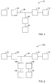
- FIG 2 is a schematic view of an exemplary embodiment wind turbine power system 100 including an energy storage system 102.
- Wind turbine power system 100 is substantially similar to wind turbine power system 10, (shown in Figure 1) and components of wind turbine power system 100 that are identical to components of wind turbine power system 10 are identified in Figure 2 using the same reference numerals used in Figure 1.
- Energy storage system 102 is coupled in electrical communication to bus 16 between wind turbine generator 12 and grid interface system 14 via a battery charge controller 104.
- energy storage system 102 is a vanadium redox battery-electrical storage system (VRB-ESS) 102 and controller 14 is a 3MW DC/DC bidirectional buck/boost converter.
- VRB-ESS vanadium redox battery-electrical storage system
- VRB-ESS 102 serves as a buffer between variable supply sources such as wind turbine generator 12 and the firm competitive requirements of a power contract such as grid 14.
- VRB-ESS 102 adds capacity value to non-firm resources such as wind and Photo-voltaic (PV).
- PV Photo-voltaic
- One to one response time makes it capable of charging and discharging over the same duration.
- VRB-ESS 102 also provides stabilization of wind turbine output and is a source of reactive energy.
- VRB-ESS 102 facilitates storing energy in multi megawatt ranges and for durations of hours or days - from any available input source. The stored energy can then be provided back to grid interface unit 20 or supplied to critical load 22 as required and directed.
- VRB-ESS 102 is configured to supply steady power in times when the wind is varying, and to continue to supply power for a period of time when the wind is gone altogether.
- VRB-ESS 102 is uniquely capable of being charged as quickly as it is discharged and is able to respond to all forms of power quality variations and so can be operated in a UPS mode as well.
- VRB-ESS 102 is fully rated to provide volt-amperes reactive (VARS) at nameplate on a continuous basis either when charging or discharging.
- VARS volt-amperes reactive
- VRB-ESS 102 is configured to store bulk power storage in a DC link of a converter in a system utilizing multiple interleaved insulated gate bipolar transistors (IGBT) converters to convert the battery voltage to AC.
- IGBT interleaved insulated gate bipolar transistors
- controller 104 is configured to facilitate directing any extra power from wind turbine generator 12 to charge VRB-ESS 102, to backup critical load 22, and/or to power grid 14. Controller 104 is also configured to facilitate preventing VRB-ESS 102 from over-charging.
- FIG 3 is schematic view of an exemplary embodiment of a multiple wind turbine power system 200 including a plurality of wind turbine generators 202 coupled in parallel configuration.
- Wind turbine power system 200 is substantially similar to wind turbine power system 100, (shown in Figure 2) and components of wind turbine power system 200 that are identical to components of wind turbine power system 100 are identified in Figure 3 using the same reference numerals used in Figure 2.
- wind turbine generators 202 provide power to grid 14 via bus 16 including grid interface unit 18 and a grid interface unit 204. Wind turbine generators 202 also provide power to critical load 22 via grid interface unit 206.
- each wind turbine generator 12 is a 2.7MW wind turbine generator
- bus 16 is a 1100VDC common DC bus
- grid interface device 18 is a 2.7MW AC/DC inverter
- grid interface device 204 is a 9MVA bidirectional AC/DC
- DC/AC inverter DC/AC inverter
- grid interface 206 is a 300KW DC/AC inverter.
- System 200 also includes a VRB-ESS 102 coupled in electrical communication to bus 16 via a battery charge controller 208.
- controller 208 is a 9MW DC/DC bidirectional buck/boost converter.
- VRB-ESS 102 facilitates serving several functions. During power failures, provides power to pitch control systems to adjust blade pitch as needed. Furthermore, most power systems are also configured with an uninterruptible power system (UPS), VRB-ESS 102 is configured to provide power to the UPS as backup power to auxiliary loads.
- UPS uninterruptible power system
- VRB-ESS 102 and controller 104 are configured to absorb the entire wind turbine generator 12 output power for dynamic braking. This function is ordinarily handled by dissipating the power in large resistors. VRB-ESS 102 facilitates eliminating these very large resistors and is more efficient than the resistors.
- the above-described invention provides a cost-effective and reliable method for coupling an energy storage system to a variable energy supply system to be able to facilitate supplying a consistent energy output during fluctuating energy demands, storing energy in times of strong wind, and continuing to provide power when the wind speed is low.
- Positioning a VRB-ESS in a wind turbine power system facilitates directing extra power from a wind turbine generator to store power in the VRB-ESS, to backup critical loads, and/or to power a utility grid.
- the VRB-ESS facilitates absorbing output power for dynamic braking.
- VRB-ESS Exemplary embodiments of a VRB-ESS are described above in detail.
- the VRB-ESS is not limited to the specific embodiments described herein, but rather, components of each system may be utilized independently and separately from other components described herein.
- VRB-ESS can also be used in combination with other variable energy supply systems, and is not limited to practice with only wind generator turbines as described herein. Rather, various embodiments of the present invention can be implemented and utilized in connection with many other generators and variable energy supply systems.
- wind turbine power system 10 wind turbine power system 12 wind turbine generator 14 grid 16 bus 18 grid interface unit 20 grid interface unit 22 critical load 24 grid interface unit 100 wind turbine power system 102 VRB-ESS 104 controller 200 wind turbine power system 202 wind turbine generators 204 grid interface unit 206 grid interface unit 208 controller
Abstract
Description
- This invention relates generally to energy storage systems, and more particularly, methods and apparatus for coupling an energy storage system to a variable energy supply system.
- At least some known wind generation systems produce a fluctuating or intermittent power output due to the variability of wind speed. When multiple generators are electrically coupled together, i.e. in arrangements known as wind farms, the fluctuation in total power output may be reduced. Under ideal conditions the variations of power output will decrease at a factor of 1/√n, where n represents the number of wind generators coupled together. In areas where wind penetration may be high, coupling a large number of generators generally reduces the overall power fluctuations on a system wide basis, but may still cause power swing stability concerns. Generally the volatile nature of wind generation output limits the amount of wind generation that can be connected to the grid without causing voltage stability problems. As such, wind power generation is generally considered a non-firm resource for system planning purposes.
- It is well known that the demand for electric power fluctuates. Normally power fluctuations occur on a relatively regular basis. For example, in a typical residential electric power grid, generally demand for electric power is low at night, peaks during the morning, levels out during the day, and peaks again in the late afternoon. However, there are circumstances where the demand for electric power suddenly and irregularly increases. From the perspective of an electric power utility company, the associated increase in electric power demand occasioned during such occasions may be difficult to accommodate because the electric power demand are generally short lived.
- For example, at least some known electric energy storage systems include banks of electric batteries. Known battery installations are used to provide electric power in emergency or power-failure circumstances, but generally can not be used to provide supplemental power during demand peaks. For example, known lead-acid batteries are used as standby power sources that may provide emergency lighting and/or standby power sources for telephone exchanges. However, such batteries either do not have adequate electric energy storage capacity to meet the demands of energy storage systems, or are expensive. To facilitate accommodating short lived electric power demand increases, at least some known electric power transmission system are coupled to electric energy storage system to an so that the energy storage system may be utilized, or turned on, to provide additional electric power during peak demand.
- In one aspect according to the present invention, a method for coupling an energy storage system to a variable energy supply system is provided. The method includes providing an energy storage system including at least one Vanadium redox battery and at least one battery charge controller. The method also includes electrically coupling the at least one battery charge controller to the variable energy supply system such that the at least one battery is configured to supply a substantially consistent energy output during fluctuating energy loads of the energy supply system.
- In another aspect, a power system for supplying power to a grid is provided. The system a variable energy supply system and a plurality of grid interface units electrically coupled to the variable energy supply system via an electrical bus. The system also includes a Vanadium redox battery electrical storage system configured to store power from the variable energy supply system and supply power to the grid.
- In a further aspect, an electrical storage system is provided. The system includes a Vanadium redox battery electrical storage system and a battery charge controller in electrical communication with the battery and a variable energy supply system. The controller is configured to direct electrical power from the variable energy supply system to at least one of the battery and/or a utility power grid.
- Various aspects and embodiments of the present invention will now be described in connection with the accompanying drawings, in which:
- Figure 1 is a schematic view of an exemplary wind turbine power system.
- Figure 2 is a schematic view of an exemplary wind turbine power system including an energy storage system.
- Figure 3 is a schematic view of an exemplary embodiment of a multiple wind turbine power system.
- Various embodiments of the present invention are directed to a vanadium-based reduction/oxidation (redox) regenerative energy storage system that converts chemical energy into electrical energy for use with wind generation systems. While the embodiments of the invention are described and illustrated in the context of a wind turbine power system, the invention is not limited to wind turbine power systems. The embodiments set forth herein are therefore exemplary only and represent various embodiments of the invention, but are not conclusive of all embodiments. As explained below, these embodiments contribute towards allowing power generating systems to store energy, as well as, provide supplemental power to an electric power grid during demand peaks or store during off-peak times.
- Figure 1 is a schematic of a wind
turbine power system 10 including awind turbine generator 12 coupled in electrical communication with apower utility grid 14. In the exemplary embodiment,wind turbine generator 12 provides power togrid 14 via abus 16 including agrid interface unit 18 and agrid interface unit 20.Wind turbine generator 12 also provides power for acritical load 22 coupled in series tobus 16 via agrid interface unit 24. In the exemplary embodiment,wind turbine generator 12 is a 2.7MW wind turbine generator,bus 16 is a 1100VDC common DC bus,grid interface device 18 is a 2.7MW AC/DC inverter,grid interface device 20 is a 3MVA bidirectional AC/DC, DC/AC inverter, andgrid interface 24 is a 100KW DC/AC inverter. Whilesystem 10 is efficient during high wind speeds, it is less efficient during fluctuating or intermittent wind speeds and thus power output togrid system 14 varies due to the variability of the wind speed. - Figure 2 is a schematic view of an exemplary embodiment wind
turbine power system 100 including anenergy storage system 102. Windturbine power system 100 is substantially similar to windturbine power system 10, (shown in Figure 1) and components of windturbine power system 100 that are identical to components of windturbine power system 10 are identified in Figure 2 using the same reference numerals used in Figure 1. -
Energy storage system 102 is coupled in electrical communication tobus 16 betweenwind turbine generator 12 andgrid interface system 14 via abattery charge controller 104. In the exemplary embodiment,energy storage system 102 is a vanadium redox battery-electrical storage system (VRB-ESS) 102 andcontroller 14 is a 3MW DC/DC bidirectional buck/boost converter. - In the exemplary embodiment, VRB-ESS 102 serves as a buffer between variable supply sources such as
wind turbine generator 12 and the firm competitive requirements of a power contract such asgrid 14. In alternative embodiments, VRB-ESS 102 adds capacity value to non-firm resources such as wind and Photo-voltaic (PV). One to one response time makes it capable of charging and discharging over the same duration. VRB-ESS 102 also provides stabilization of wind turbine output and is a source of reactive energy. - VRB-ESS 102 facilitates storing energy in multi megawatt ranges and for durations of hours or days - from any available input source. The stored energy can then be provided back to
grid interface unit 20 or supplied tocritical load 22 as required and directed. VRB-ESS 102 is configured to supply steady power in times when the wind is varying, and to continue to supply power for a period of time when the wind is gone altogether. - VRB-ESS 102 is uniquely capable of being charged as quickly as it is discharged and is able to respond to all forms of power quality variations and so can be operated in a UPS mode as well. For loads which require reactive energy, VRB-ESS 102 is fully rated to provide volt-amperes reactive (VARS) at nameplate on a continuous basis either when charging or discharging. And as such, VRB-ESS 102 is configured to store bulk power storage in a DC link of a converter in a system utilizing multiple interleaved insulated gate bipolar transistors (IGBT) converters to convert the battery voltage to AC.
- In the exemplary embodiment,
controller 104 is configured to facilitate directing any extra power fromwind turbine generator 12 to charge VRB-ESS 102, to backupcritical load 22, and/or topower grid 14.Controller 104 is also configured to facilitate preventing VRB-ESS 102 from over-charging. - Figure 3 is schematic view of an exemplary embodiment of a multiple wind
turbine power system 200 including a plurality ofwind turbine generators 202 coupled in parallel configuration. Windturbine power system 200 is substantially similar to windturbine power system 100, (shown in Figure 2) and components of windturbine power system 200 that are identical to components of windturbine power system 100 are identified in Figure 3 using the same reference numerals used in Figure 2. - In the exemplary embodiment,
wind turbine generators 202 provide power togrid 14 viabus 16 includinggrid interface unit 18 and agrid interface unit 204.Wind turbine generators 202 also provide power tocritical load 22 viagrid interface unit 206. In the exemplary embodiment, eachwind turbine generator 12 is a 2.7MW wind turbine generator,bus 16 is a 1100VDC common DC bus,grid interface device 18 is a 2.7MW AC/DC inverter,grid interface device 204 is a 9MVA bidirectional AC/DC, DC/AC inverter, andgrid interface 206 is a 300KW DC/AC inverter.System 200 also includes a VRB-ESS 102 coupled in electrical communication tobus 16 via abattery charge controller 208. In the exemplary embodiment,controller 208 is a 9MW DC/DC bidirectional buck/boost converter. - As utilized within embodiments of the present invention, VRB-ESS 102 facilitates serving several functions. During power failures, provides power to pitch control systems to adjust blade pitch as needed. Furthermore, most power systems are also configured with an uninterruptible power system (UPS), VRB-ESS 102 is configured to provide power to the UPS as backup power to auxiliary loads.
- Another advantage of these configurations is the "dynamic braking" energy is handled by the battery storage system. In the exemplary embodiment, VRB-
ESS 102 andcontroller 104 are configured to absorb the entirewind turbine generator 12 output power for dynamic braking. This function is ordinarily handled by dissipating the power in large resistors. VRB-ESS 102 facilitates eliminating these very large resistors and is more efficient than the resistors. - The above-described invention provides a cost-effective and reliable method for coupling an energy storage system to a variable energy supply system to be able to facilitate supplying a consistent energy output during fluctuating energy demands, storing energy in times of strong wind, and continuing to provide power when the wind speed is low. Positioning a VRB-ESS in a wind turbine power system facilitates directing extra power from a wind turbine generator to store power in the VRB-ESS, to backup critical loads, and/or to power a utility grid. Furthermore, the VRB-ESS facilitates absorbing output power for dynamic braking.
- Exemplary embodiments of a VRB-ESS are described above in detail. The VRB-ESS is not limited to the specific embodiments described herein, but rather, components of each system may be utilized independently and separately from other components described herein. For example, VRB-ESS can also be used in combination with other variable energy supply systems, and is not limited to practice with only wind generator turbines as described herein. Rather, various embodiments of the present invention can be implemented and utilized in connection with many other generators and variable energy supply systems.
- While the invention has been described in terms of various specific embodiments, those skilled in the art will recognize that the invention can be practiced with modification within the spirit and scope of the claims.
-
10 wind turbine power system 12 wind turbine generator 14 grid 16 bus 18 grid interface unit 20 grid interface unit 22 critical load 24 grid interface unit 100 wind turbine power system 102 VRB- ESS 104 controller 200 wind turbine power system 202 wind turbine generators 204 grid interface unit 206 grid interface unit 208 controller
Claims (10)
- A power system (10) for supplying power to a grid (14), said system comprising:a variable energy supply system;a plurality of grid interface units (18, 20) electrically coupled to said variable energy supply system via an electrical bus (16); anda Vanadium redox battery electrical storage system (102) configured to store power from said variable energy supply system and supply power to the grid.
- A power system (10) in accordance with Claim 1 wherein said variable energy supply system comprises at least one wind turbine generator (12).
- A power system (10) in accordance with Claim 1 or Claim 2 wherein said plurality of grid interface units (18, 20) comprise at least one of an inverter and a converter.
- A power system (10) in accordance with any preceding Claim wherein said Vanadium redox battery electrical storage system (102) comprises a Vanadium redox battery coupled to a battery charge controller (104).
- A power system (10) in accordance with Claim 4 wherein said battery charge controller (104) is configured to direct excess power from said variable energy supply system to charge said Vanadium redox battery, back up a critical load, and power the grid (14).
- A power system (10) in accordance with Claim 4 or Claim 5 wherein said battery charge controller (104) is configured to direct electrical power to a wind turbine pitch control system in the event of a pitch control system failure.
- A power system (10) in accordance with any one of Claims 4 to 6 wherein said battery charge controller (104) is configured to direct electrical power to an auxiliary load.
- An electrical storage system, said system comprising:a Vanadium redox battery electrical storage system (102); anda battery charge controller (104) in electrical communication with said battery and a variable energy supply system, said controller configured to direct electrical power from said variable energy supply system to at least one of said battery and/or a utility power grid (14).
- An electrical storage system in accordance with Claim 8 wherein said variable energy supply system comprises at least one wind turbine generator (12).
- An electrical storage system in accordance with Claim 8 or Claim 9 wherein said controller (104) is a bidirectional buck/boost converter.
Applications Claiming Priority (1)
| Application Number | Priority Date | Filing Date | Title |
|---|---|---|---|
| US11/247,836 US7923965B2 (en) | 2005-10-10 | 2005-10-10 | Methods for coupling an energy storage system to a variable energy supply system |
Publications (3)
| Publication Number | Publication Date |
|---|---|
| EP1772939A2 true EP1772939A2 (en) | 2007-04-11 |
| EP1772939A3 EP1772939A3 (en) | 2012-04-18 |
| EP1772939B1 EP1772939B1 (en) | 2017-09-27 |
Family
ID=37685215
Family Applications (1)
| Application Number | Title | Priority Date | Filing Date |
|---|---|---|---|
| EP06255189.0A Not-in-force EP1772939B1 (en) | 2005-10-10 | 2006-10-09 | Methods and apparatus for coupling an energy storage system to a variable energy supply system |
Country Status (6)
| Country | Link |
|---|---|
| US (2) | US7923965B2 (en) |
| EP (1) | EP1772939B1 (en) |
| CN (1) | CN101013819B (en) |
| AU (1) | AU2006225334B2 (en) |
| BR (1) | BRPI0604436B1 (en) |
| CA (1) | CA2562609C (en) |
Cited By (9)
| Publication number | Priority date | Publication date | Assignee | Title |
|---|---|---|---|---|
| GB2446432A (en) * | 2007-02-07 | 2008-08-13 | Semplice Energy Ltd | A generator connection arrangement |
| WO2009027520A2 (en) * | 2007-08-31 | 2009-03-05 | Vestas Wind Systems A/S | Modular converter system with interchangeable converter modules |
| WO2012020148A1 (en) | 2010-08-11 | 2012-02-16 | Ingeteam Energy S.A. | Management system for variable-resource energy generation systems |
| CN103595116A (en) * | 2013-11-22 | 2014-02-19 | 烟台卓越新能源科技有限公司 | Small wind, light, electricity and heat combined energy system |
| US20140375056A1 (en) * | 2011-12-20 | 2014-12-25 | United Technologies Corporation | Method of operating a power generation system |
| EP2868913A1 (en) * | 2013-11-05 | 2015-05-06 | Openhydro IP Limited | Turbulence compensation system and method for turbine generators |
| EP3270482A4 (en) * | 2015-03-13 | 2018-09-12 | Kabushiki Kaisha Toshiba | Storage battery device |
| EP2753825B1 (en) | 2011-09-05 | 2019-05-08 | XEMC Darwind BV | Generating auxiliary power for a wind turbine |
| EP2169800B1 (en) * | 2008-09-30 | 2022-07-27 | General Electric Company | Power generation system and method for storing electrical energy |
Families Citing this family (55)
| Publication number | Priority date | Publication date | Assignee | Title |
|---|---|---|---|---|
| JP4796974B2 (en) * | 2007-01-26 | 2011-10-19 | 株式会社日立産機システム | Hybrid system of wind power generator and power storage device, wind power generation system, power control device |
| US7855005B2 (en) * | 2007-02-12 | 2010-12-21 | Deeya Energy, Inc. | Apparatus and methods of determination of state of charge in a redox flow battery |
| DK2176545T3 (en) | 2007-07-12 | 2014-12-15 | Windurance Llc | Method and apparatus for nettabs-flow for wind turbine pitch-management system |
| US8587150B2 (en) * | 2008-02-28 | 2013-11-19 | Deeya Energy, Inc. | Method and modular system for charging a battery |
| US7952232B2 (en) * | 2008-03-13 | 2011-05-31 | General Electric Company | Wind turbine energy storage and frequency control |
| US7927731B2 (en) * | 2008-07-01 | 2011-04-19 | Deeya Energy, Inc. | Redox flow cell |
| US7820321B2 (en) | 2008-07-07 | 2010-10-26 | Enervault Corporation | Redox flow battery system for distributed energy storage |
| US8785023B2 (en) | 2008-07-07 | 2014-07-22 | Enervault Corparation | Cascade redox flow battery systems |
| US10089443B2 (en) | 2012-05-15 | 2018-10-02 | Baxter International Inc. | Home medical device systems and methods for therapy prescription and tracking, servicing and inventory |
| CN102150319B (en) * | 2008-09-30 | 2013-12-04 | 日本碍子株式会社 | Method for controlling sodium-sulfur batteries |
| US8236463B2 (en) * | 2008-10-10 | 2012-08-07 | Deeya Energy, Inc. | Magnetic current collector |
| US20100092843A1 (en) * | 2008-10-10 | 2010-04-15 | Deeya Energy Technologies, Inc. | Venturi pumping system in a hydrogen gas circulation of a flow battery |
| CN102246385B (en) * | 2008-10-10 | 2015-07-29 | 艾默吉电力系统股份有限公司 | For determining the method and apparatus of the state-of-charge of battery |
| US8231993B2 (en) * | 2008-10-10 | 2012-07-31 | Deeya Energy, Inc. | Flexible multi-walled tubing assembly |
| US8883297B2 (en) * | 2008-10-10 | 2014-11-11 | Imergy Power Systems, Inc. | Methods for bonding porous flexible membranes using solvent |
| CN102246338B (en) * | 2008-10-10 | 2014-06-11 | 迪亚能源股份有限公司 | Thermal control of a flow cell battery |
| US8230736B2 (en) * | 2008-10-10 | 2012-07-31 | Deeya Energy, Inc. | Level sensor for conductive liquids |
| WO2010138945A2 (en) * | 2009-05-28 | 2010-12-02 | Deeya Energy, Inc. | Preparation of flow cell battery electrolytes from raw materials |
| WO2010138943A2 (en) * | 2009-05-28 | 2010-12-02 | Deeya Energy, Inc. | Electrolyte compositions |
| US8587255B2 (en) | 2009-05-28 | 2013-11-19 | Deeya Energy, Inc. | Control system for a flow cell battery |
| US8349477B2 (en) * | 2009-05-28 | 2013-01-08 | Deeya Energy, Inc. | Optical leak detection sensor |
| WO2010138948A2 (en) | 2009-05-28 | 2010-12-02 | Deeya Energy, Inc. | Buck-boost control circuit |
| CN102460811B (en) | 2009-05-28 | 2015-11-25 | 艾默吉电力系统股份有限公司 | Redox flow cell rebalancing |
| WO2010138947A2 (en) * | 2009-05-29 | 2010-12-02 | Deeya Energy, Inc. | Methods of producing hydrochloric acid from hydrogen gas and chlorine gas |
| US8839254B2 (en) * | 2009-06-26 | 2014-09-16 | Microsoft Corporation | Precomputation for data center load balancing |
| US20110137481A1 (en) * | 2009-12-23 | 2011-06-09 | General Electric Company | System and metehod for providing power grid energy from a battery |
| US9086055B2 (en) * | 2010-01-11 | 2015-07-21 | General Electric Company | Lubrication of fluid turbine gearbox during idling or loss of electric grid |
| US8951665B2 (en) * | 2010-03-10 | 2015-02-10 | Imergy Power Systems, Inc. | Methods for the preparation of electrolytes for chromium-iron redox flow batteries |
| US9207993B2 (en) | 2010-05-13 | 2015-12-08 | Microsoft Technology Licensing, Llc | Dynamic application placement based on cost and availability of energy in datacenters |
| US20110278928A1 (en) * | 2010-05-17 | 2011-11-17 | Microsoft Corporation | Wind-powered data center |
| US9281535B2 (en) | 2010-08-12 | 2016-03-08 | Imergy Power Systems, Inc. | System dongle |
| US8849469B2 (en) | 2010-10-28 | 2014-09-30 | Microsoft Corporation | Data center system that accommodates episodic computation |
| US9063738B2 (en) | 2010-11-22 | 2015-06-23 | Microsoft Technology Licensing, Llc | Dynamically placing computing jobs |
| US9269982B2 (en) | 2011-01-13 | 2016-02-23 | Imergy Power Systems, Inc. | Flow cell stack |
| WO2012112147A1 (en) * | 2011-02-16 | 2012-08-23 | Hewlett-Packard Development Company, L.P. | Providing power in an electronic device |
| US8569994B2 (en) * | 2011-03-15 | 2013-10-29 | General Electric Company | Charging device, system, and method of supplying power to at least one load |
| US8916281B2 (en) | 2011-03-29 | 2014-12-23 | Enervault Corporation | Rebalancing electrolytes in redox flow battery systems |
| US8980484B2 (en) | 2011-03-29 | 2015-03-17 | Enervault Corporation | Monitoring electrolyte concentrations in redox flow battery systems |
| US20140055080A1 (en) * | 2011-04-22 | 2014-02-27 | Mitsubishi Electric Corporation | Charging apparatus |
| US9595054B2 (en) | 2011-06-27 | 2017-03-14 | Microsoft Technology Licensing, Llc | Resource management for cloud computing platforms |
| US9450838B2 (en) | 2011-06-27 | 2016-09-20 | Microsoft Technology Licensing, Llc | Resource management for cloud computing platforms |
| US8907510B2 (en) | 2012-03-09 | 2014-12-09 | General Electric Company | Method and systems for operating a wind turbine |
| US9369076B2 (en) * | 2012-07-12 | 2016-06-14 | General Electric Company | Dynamic braking system for an electric power system and method of operating the same |
| US8664788B1 (en) | 2012-09-07 | 2014-03-04 | General Electric Company | Method and systems for operating a wind turbine using dynamic braking in response to a grid event |
| ES2685910T3 (en) * | 2012-09-28 | 2018-10-15 | Enrichment Technology Company Ltd. | Energy storage system |
| US8933571B2 (en) * | 2012-10-17 | 2015-01-13 | Zinovy D Grinblat | Method and system for fully utilizing wind energy in a wind energy generating system |
| US9933804B2 (en) | 2014-07-11 | 2018-04-03 | Microsoft Technology Licensing, Llc | Server installation as a grid condition sensor |
| US10234835B2 (en) | 2014-07-11 | 2019-03-19 | Microsoft Technology Licensing, Llc | Management of computing devices using modulated electricity |
| JP6397688B2 (en) * | 2014-08-07 | 2018-09-26 | 株式会社東芝 | Storage battery control device and storage battery control method |
| US10554048B2 (en) * | 2015-05-18 | 2020-02-04 | University Of North Carolina At Charlotte | Battery energy storage system controller systems and methods |
| KR101860638B1 (en) * | 2016-09-26 | 2018-07-05 | 한국전력공사 | Method and system for controlling energy storage system with demand control and uninterrupted power supply function |
| GB2568637B (en) * | 2016-10-05 | 2021-12-22 | Lockheed Martin Energy Llc | Energy storage units and systems with segmented branch interconnects |
| US10288041B2 (en) | 2017-01-09 | 2019-05-14 | Kevin R. Williams | Renewable energy system having a distributed energy storage systems and photovoltaic cogeneration |
| WO2019060571A1 (en) | 2017-09-20 | 2019-03-28 | Etagen, Inc. | Dc-dc converter in a non-steady system |
| CN116131421B (en) * | 2023-01-17 | 2024-02-13 | 中国长江电力股份有限公司 | System and method for converting braking energy of hydroelectric generating set into black start power supply |
Citations (10)
| Publication number | Priority date | Publication date | Assignee | Title |
|---|---|---|---|---|
| US4362791A (en) | 1980-06-17 | 1982-12-07 | Agency Of Industrial Science & Technology | Redox battery |
| US5225712A (en) | 1991-02-01 | 1993-07-06 | U.S. Windpower, Inc. | Variable speed wind turbine with reduced power fluctuation and a static VAR mode of operation |
| US6809431B1 (en) | 1998-09-26 | 2004-10-26 | Dewind Ag | Control logic for a wind energy system |
| US20050074665A1 (en) | 2001-11-16 | 2005-04-07 | Squirrel Holdings Ltd | System for storing and/or transforming energy from sources at variable voltage and frequency |
| US20050147871A1 (en) | 2002-04-23 | 2005-07-07 | Toshio Shigematsu | Method for operating redox flow battery system |
| US20050156432A1 (en) | 2004-01-15 | 2005-07-21 | Hennessy Timothy D.J. | Power generation system incorporating a vanadium redox battery and a direct current wind turbine generator |
| US20050158614A1 (en) | 2004-01-15 | 2005-07-21 | Hennessy Timothy D.J. | System and method for optimizing efficiency and power output from a vanadium redox battery energy storage system |
| US20050156431A1 (en) | 2004-01-15 | 2005-07-21 | Hennessy Timothy D.J. | Vanadium redox battery energy storage and power generation system incorporating and optimizing diesel engine generators |
| US20060171086A1 (en) | 2005-02-01 | 2006-08-03 | Vrb Power Systems Inc. | Method for retrofitting wind turbine farms |
| US20070072067A1 (en) | 2005-09-23 | 2007-03-29 | Vrb Power Systems Inc. | Vanadium redox battery cell stack |
Family Cites Families (19)
| Publication number | Priority date | Publication date | Assignee | Title |
|---|---|---|---|---|
| US4786567A (en) | 1986-02-11 | 1988-11-22 | Unisearch Limited | All-vanadium redox battery |
| MY113980A (en) | 1993-11-17 | 2002-07-31 | Jd Holding Inc | Stabilised electrolyte solutions, methods of preparation thereof and redox cells and batteries containing stabilised electrolyte solutions. |
| NZ306364A (en) | 1995-05-03 | 1999-04-29 | Unisearch Ltd | High energy density vanadium electrolyte solutions, preparation thereof and redox cells and batteries containing the electrolyte solution |
| US5610802A (en) | 1995-05-23 | 1997-03-11 | Zb B Technologies, Inc. | Compact energy storage system |
| US6870279B2 (en) * | 1998-01-05 | 2005-03-22 | Capstone Turbine Corporation | Method and system for control of turbogenerator power and temperature |
| US20020166324A1 (en) * | 1998-04-02 | 2002-11-14 | Capstone Turbine Corporation | Integrated turbine power generation system having low pressure supplemental catalytic reactor |
| US6134124A (en) * | 1999-05-12 | 2000-10-17 | Abb Power T&D Company Inc. | Universal distributed-resource interface |
| DE10044096A1 (en) * | 2000-09-07 | 2002-04-04 | Aloys Wobben | Off-grid and method for operating an off-grid |
| PL212009B1 (en) * | 2001-09-28 | 2012-07-31 | Aloys Wobben | Method for operating a wind park |
| JP2003222070A (en) * | 2002-01-30 | 2003-08-08 | Mitsubishi Heavy Ind Ltd | Windmill |
| JP4023171B2 (en) * | 2002-02-05 | 2007-12-19 | トヨタ自動車株式会社 | LOAD DRIVE DEVICE, CHARGE CONTROL METHOD FOR POWER STORAGE DEVICE IN LOAD DRIVE DEVICE, AND COMPUTER-READABLE RECORDING MEDIUM CONTAINING PROGRAM FOR CAUSING COMPUTER TO EXECUTE CHARGE CONTROL |
| CA2383445A1 (en) * | 2002-04-25 | 2003-10-25 | Wayne Ernest Conrad | Improved means of controlling a vacuum cleaner employing a separate suction and brush motor |
| US6768047B2 (en) * | 2002-06-13 | 2004-07-27 | Koninklijke Philips Electronics N.V. | Autonomous solid state lighting system |
| US7078825B2 (en) * | 2002-06-18 | 2006-07-18 | Ingersoll-Rand Energy Systems Corp. | Microturbine engine system having stand-alone and grid-parallel operating modes |
| AU2003293372B2 (en) * | 2002-12-06 | 2008-08-07 | Electric Power Research Institute, Inc. | Electrical power supply |
| US6984897B2 (en) * | 2003-01-23 | 2006-01-10 | Spellman High Voltage Electronics Corporation | Electro-mechanical energy conversion system having a permanent magnet machine with stator, resonant transfer link and energy converter controls |
| JP4229765B2 (en) * | 2003-06-18 | 2009-02-25 | ナブテスコ株式会社 | Wind turbine blade pitch angle control device |
| EP1644629B1 (en) * | 2003-07-02 | 2008-09-10 | Tiax LLC | Free piston stirling engine control |
| WO2005036684A2 (en) * | 2003-10-10 | 2005-04-21 | Nuvera Fuel Cells, Inc. | Power electronics for fuel cell power system |
-
2005
- 2005-10-10 US US11/247,836 patent/US7923965B2/en active Active
-
2006
- 2006-10-05 CA CA2562609A patent/CA2562609C/en active Active
- 2006-10-09 BR BRPI0604436-0A patent/BRPI0604436B1/en active IP Right Grant
- 2006-10-09 EP EP06255189.0A patent/EP1772939B1/en not_active Not-in-force
- 2006-10-10 CN CN200610064271.9A patent/CN101013819B/en active Active
- 2006-10-10 AU AU2006225334A patent/AU2006225334B2/en not_active Ceased
-
2011
- 2011-02-22 US US13/032,322 patent/US20110204637A1/en not_active Abandoned
Patent Citations (10)
| Publication number | Priority date | Publication date | Assignee | Title |
|---|---|---|---|---|
| US4362791A (en) | 1980-06-17 | 1982-12-07 | Agency Of Industrial Science & Technology | Redox battery |
| US5225712A (en) | 1991-02-01 | 1993-07-06 | U.S. Windpower, Inc. | Variable speed wind turbine with reduced power fluctuation and a static VAR mode of operation |
| US6809431B1 (en) | 1998-09-26 | 2004-10-26 | Dewind Ag | Control logic for a wind energy system |
| US20050074665A1 (en) | 2001-11-16 | 2005-04-07 | Squirrel Holdings Ltd | System for storing and/or transforming energy from sources at variable voltage and frequency |
| US20050147871A1 (en) | 2002-04-23 | 2005-07-07 | Toshio Shigematsu | Method for operating redox flow battery system |
| US20050156432A1 (en) | 2004-01-15 | 2005-07-21 | Hennessy Timothy D.J. | Power generation system incorporating a vanadium redox battery and a direct current wind turbine generator |
| US20050158614A1 (en) | 2004-01-15 | 2005-07-21 | Hennessy Timothy D.J. | System and method for optimizing efficiency and power output from a vanadium redox battery energy storage system |
| US20050156431A1 (en) | 2004-01-15 | 2005-07-21 | Hennessy Timothy D.J. | Vanadium redox battery energy storage and power generation system incorporating and optimizing diesel engine generators |
| US20060171086A1 (en) | 2005-02-01 | 2006-08-03 | Vrb Power Systems Inc. | Method for retrofitting wind turbine farms |
| US20070072067A1 (en) | 2005-09-23 | 2007-03-29 | Vrb Power Systems Inc. | Vanadium redox battery cell stack |
Cited By (14)
| Publication number | Priority date | Publication date | Assignee | Title |
|---|---|---|---|---|
| GB2446432A (en) * | 2007-02-07 | 2008-08-13 | Semplice Energy Ltd | A generator connection arrangement |
| WO2009027520A2 (en) * | 2007-08-31 | 2009-03-05 | Vestas Wind Systems A/S | Modular converter system with interchangeable converter modules |
| WO2009027520A3 (en) * | 2007-08-31 | 2009-06-25 | Vestas Wind Sys As | Modular converter system with interchangeable converter modules |
| EP2169800B1 (en) * | 2008-09-30 | 2022-07-27 | General Electric Company | Power generation system and method for storing electrical energy |
| WO2012020148A1 (en) | 2010-08-11 | 2012-02-16 | Ingeteam Energy S.A. | Management system for variable-resource energy generation systems |
| EP2753825B1 (en) | 2011-09-05 | 2019-05-08 | XEMC Darwind BV | Generating auxiliary power for a wind turbine |
| US9294026B2 (en) * | 2011-12-20 | 2016-03-22 | United Technologies Corporation | Method of operating a power generation system |
| US20140375056A1 (en) * | 2011-12-20 | 2014-12-25 | United Technologies Corporation | Method of operating a power generation system |
| EP2868913A1 (en) * | 2013-11-05 | 2015-05-06 | Openhydro IP Limited | Turbulence compensation system and method for turbine generators |
| JP2016538819A (en) * | 2013-11-05 | 2016-12-08 | オープンハイドロ アイピー リミテッド | Power generation system, power control method, and device protection method |
| AU2014345684B2 (en) * | 2013-11-05 | 2017-10-19 | Openhydro Ip Limited | Turbulence compensation system and method for turbine generators |
| WO2015067558A1 (en) * | 2013-11-05 | 2015-05-14 | Openhydro Ip Limited | Turbulence compensation system and method for turbine generators |
| CN103595116A (en) * | 2013-11-22 | 2014-02-19 | 烟台卓越新能源科技有限公司 | Small wind, light, electricity and heat combined energy system |
| EP3270482A4 (en) * | 2015-03-13 | 2018-09-12 | Kabushiki Kaisha Toshiba | Storage battery device |
Also Published As
| Publication number | Publication date |
|---|---|
| EP1772939A3 (en) | 2012-04-18 |
| EP1772939B1 (en) | 2017-09-27 |
| BRPI0604436B1 (en) | 2018-06-05 |
| CN101013819A (en) | 2007-08-08 |
| US7923965B2 (en) | 2011-04-12 |
| BRPI0604436A (en) | 2007-08-28 |
| CA2562609C (en) | 2015-11-24 |
| AU2006225334A1 (en) | 2007-04-26 |
| US20110204637A1 (en) | 2011-08-25 |
| US20070080666A1 (en) | 2007-04-12 |
| AU2006225334B2 (en) | 2012-01-12 |
| CA2562609A1 (en) | 2007-04-10 |
| CN101013819B (en) | 2014-04-09 |
Similar Documents
| Publication | Publication Date | Title |
|---|---|---|
| EP1772939B1 (en) | Methods and apparatus for coupling an energy storage system to a variable energy supply system | |
| EP2169800B1 (en) | Power generation system and method for storing electrical energy | |
| US6949843B2 (en) | Grid-connected power systems having back-up power sources and methods of providing back-up power in grid-connected power systems | |
| Ambia et al. | Centralized power control strategy for AC-DC hybrid micro-grid system using multi-converter scheme | |
| US8941263B2 (en) | Energy storage system and method of controlling the same | |
| Zhang et al. | Research on battery supercapacitor hybrid storage and its application in microgrid | |
| US10554047B2 (en) | Control method of an electric microgrid | |
| US8148844B2 (en) | Power supply system including alternative sources | |
| CN102386635B (en) | The system of the distribution that inverter VAR supports and method | |
| US10283964B2 (en) | Predictive control for energy storage on a renewable energy system | |
| EP3206276A1 (en) | Energy storage system and management method thereof | |
| US8253271B2 (en) | Home power supply system | |
| WO2011162722A1 (en) | Energy storage system | |
| CN114096751A (en) | Full DC voltage power backup system for wind turbines | |
| Gundumalla et al. | Ramp rate control strategy for an islanded dc microgrid with hybrid energy storage system | |
| Korada et al. | Dynamic energy management in DC microgrid using composite energy storage system | |
| US10003199B2 (en) | Battery energy storage system | |
| TWI685179B (en) | power supply system | |
| Kumar et al. | Power balance for WTG-Solar PV fed DC microgrids with battery and supercapacitor support | |
| US20120068533A1 (en) | Power Supply System Including Alternative Sources-DC Power Management | |
| Saurav et al. | LVRT for Solar PV System with Grid Scale Battery Energy Storage System | |
| CN115769454A (en) | Fast frequency response of hybrid power plant | |
| CN102195295A (en) | Wind-solar-fuel storage battery hybrid grid-connected and off-grid dual-purpose system | |
| CN219918431U (en) | Wind power energy storage adjusting device | |
| AU2010358881A1 (en) | Management system for variable-resource energy generation systems |
Legal Events
| Date | Code | Title | Description |
|---|---|---|---|
| PUAI | Public reference made under article 153(3) epc to a published international application that has entered the european phase |
Free format text: ORIGINAL CODE: 0009012 |
|
| AK | Designated contracting states |
Kind code of ref document: A2 Designated state(s): AT BE BG CH CY CZ DE DK EE ES FI FR GB GR HU IE IS IT LI LT LU LV MC NL PL PT RO SE SI SK TR |
|
| AX | Request for extension of the european patent |
Extension state: AL BA HR MK YU |
|
| TPAC | Observations filed by third parties |
Free format text: ORIGINAL CODE: EPIDOSNTIPA |
|
| PUAL | Search report despatched |
Free format text: ORIGINAL CODE: 0009013 |
|
| AK | Designated contracting states |
Kind code of ref document: A3 Designated state(s): AT BE BG CH CY CZ DE DK EE ES FI FR GB GR HU IE IS IT LI LT LU LV MC NL PL PT RO SE SI SK TR |
|
| AX | Request for extension of the european patent |
Extension state: AL BA HR MK RS |
|
| RIC1 | Information provided on ipc code assigned before grant |
Ipc: H02J 7/32 20060101ALI20120313BHEP Ipc: H02J 3/38 20060101AFI20120313BHEP Ipc: H02J 3/32 20060101ALI20120313BHEP |
|
| 17P | Request for examination filed |
Effective date: 20121018 |
|
| AKX | Designation fees paid |
Designated state(s): AT BE BG CH CY CZ DE DK EE ES FI FR GB GR HU IE IS IT LI LT LU LV MC NL PL PT RO SE SI SK TR |
|
| 17Q | First examination report despatched |
Effective date: 20130829 |
|
| REG | Reference to a national code |
Ref country code: DE Ref legal event code: R079 Ref document number: 602006053707 Country of ref document: DE Free format text: PREVIOUS MAIN CLASS: H02J0003000000 Ipc: H02J0003320000 |
|
| GRAP | Despatch of communication of intention to grant a patent |
Free format text: ORIGINAL CODE: EPIDOSNIGR1 |
|
| RIC1 | Information provided on ipc code assigned before grant |
Ipc: H02J 3/32 20060101AFI20170425BHEP Ipc: H02J 3/38 20060101ALI20170425BHEP Ipc: H02J 7/34 20060101ALI20170425BHEP |
|
| INTG | Intention to grant announced |
Effective date: 20170516 |
|
| GRAS | Grant fee paid |
Free format text: ORIGINAL CODE: EPIDOSNIGR3 |
|
| GRAA | (expected) grant |
Free format text: ORIGINAL CODE: 0009210 |
|
| AK | Designated contracting states |
Kind code of ref document: B1 Designated state(s): AT BE BG CH CY CZ DE DK EE ES FI FR GB GR HU IE IS IT LI LT LU LV MC NL PL PT RO SE SI SK TR |
|
| REG | Reference to a national code |
Ref country code: GB Ref legal event code: FG4D |
|
| REG | Reference to a national code |
Ref country code: CH Ref legal event code: EP |
|
| REG | Reference to a national code |
Ref country code: AT Ref legal event code: REF Ref document number: 932850 Country of ref document: AT Kind code of ref document: T Effective date: 20171015 |
|
| REG | Reference to a national code |
Ref country code: IE Ref legal event code: FG4D |
|
| REG | Reference to a national code |
Ref country code: DE Ref legal event code: R096 Ref document number: 602006053707 Country of ref document: DE |
|
| PG25 | Lapsed in a contracting state [announced via postgrant information from national office to epo] |
Ref country code: FI Free format text: LAPSE BECAUSE OF FAILURE TO SUBMIT A TRANSLATION OF THE DESCRIPTION OR TO PAY THE FEE WITHIN THE PRESCRIBED TIME-LIMIT Effective date: 20170927 Ref country code: LT Free format text: LAPSE BECAUSE OF FAILURE TO SUBMIT A TRANSLATION OF THE DESCRIPTION OR TO PAY THE FEE WITHIN THE PRESCRIBED TIME-LIMIT Effective date: 20170927 Ref country code: SE Free format text: LAPSE BECAUSE OF FAILURE TO SUBMIT A TRANSLATION OF THE DESCRIPTION OR TO PAY THE FEE WITHIN THE PRESCRIBED TIME-LIMIT Effective date: 20170927 |
|
| REG | Reference to a national code |
Ref country code: NL Ref legal event code: MP Effective date: 20170927 |
|
| REG | Reference to a national code |
Ref country code: LT Ref legal event code: MG4D |
|
| REG | Reference to a national code |
Ref country code: AT Ref legal event code: MK05 Ref document number: 932850 Country of ref document: AT Kind code of ref document: T Effective date: 20170927 |
|
| PG25 | Lapsed in a contracting state [announced via postgrant information from national office to epo] |
Ref country code: LV Free format text: LAPSE BECAUSE OF FAILURE TO SUBMIT A TRANSLATION OF THE DESCRIPTION OR TO PAY THE FEE WITHIN THE PRESCRIBED TIME-LIMIT Effective date: 20170927 Ref country code: GR Free format text: LAPSE BECAUSE OF FAILURE TO SUBMIT A TRANSLATION OF THE DESCRIPTION OR TO PAY THE FEE WITHIN THE PRESCRIBED TIME-LIMIT Effective date: 20171228 Ref country code: BG Free format text: LAPSE BECAUSE OF FAILURE TO SUBMIT A TRANSLATION OF THE DESCRIPTION OR TO PAY THE FEE WITHIN THE PRESCRIBED TIME-LIMIT Effective date: 20171227 |
|
| PG25 | Lapsed in a contracting state [announced via postgrant information from national office to epo] |
Ref country code: NL Free format text: LAPSE BECAUSE OF FAILURE TO SUBMIT A TRANSLATION OF THE DESCRIPTION OR TO PAY THE FEE WITHIN THE PRESCRIBED TIME-LIMIT Effective date: 20170927 |
|
| PG25 | Lapsed in a contracting state [announced via postgrant information from national office to epo] |
Ref country code: RO Free format text: LAPSE BECAUSE OF FAILURE TO SUBMIT A TRANSLATION OF THE DESCRIPTION OR TO PAY THE FEE WITHIN THE PRESCRIBED TIME-LIMIT Effective date: 20170927 Ref country code: ES Free format text: LAPSE BECAUSE OF FAILURE TO SUBMIT A TRANSLATION OF THE DESCRIPTION OR TO PAY THE FEE WITHIN THE PRESCRIBED TIME-LIMIT Effective date: 20170927 Ref country code: CZ Free format text: LAPSE BECAUSE OF FAILURE TO SUBMIT A TRANSLATION OF THE DESCRIPTION OR TO PAY THE FEE WITHIN THE PRESCRIBED TIME-LIMIT Effective date: 20170927 |
|
| REG | Reference to a national code |
Ref country code: DE Ref legal event code: R119 Ref document number: 602006053707 Country of ref document: DE |
|
| PG25 | Lapsed in a contracting state [announced via postgrant information from national office to epo] |
Ref country code: IT Free format text: LAPSE BECAUSE OF FAILURE TO SUBMIT A TRANSLATION OF THE DESCRIPTION OR TO PAY THE FEE WITHIN THE PRESCRIBED TIME-LIMIT Effective date: 20170927 Ref country code: IS Free format text: LAPSE BECAUSE OF FAILURE TO SUBMIT A TRANSLATION OF THE DESCRIPTION OR TO PAY THE FEE WITHIN THE PRESCRIBED TIME-LIMIT Effective date: 20180127 Ref country code: EE Free format text: LAPSE BECAUSE OF FAILURE TO SUBMIT A TRANSLATION OF THE DESCRIPTION OR TO PAY THE FEE WITHIN THE PRESCRIBED TIME-LIMIT Effective date: 20170927 Ref country code: AT Free format text: LAPSE BECAUSE OF FAILURE TO SUBMIT A TRANSLATION OF THE DESCRIPTION OR TO PAY THE FEE WITHIN THE PRESCRIBED TIME-LIMIT Effective date: 20170927 Ref country code: SK Free format text: LAPSE BECAUSE OF FAILURE TO SUBMIT A TRANSLATION OF THE DESCRIPTION OR TO PAY THE FEE WITHIN THE PRESCRIBED TIME-LIMIT Effective date: 20170927 |
|
| REG | Reference to a national code |
Ref country code: CH Ref legal event code: PL |
|
| PG25 | Lapsed in a contracting state [announced via postgrant information from national office to epo] |
Ref country code: MC Free format text: LAPSE BECAUSE OF FAILURE TO SUBMIT A TRANSLATION OF THE DESCRIPTION OR TO PAY THE FEE WITHIN THE PRESCRIBED TIME-LIMIT Effective date: 20170927 |
|
| REG | Reference to a national code |
Ref country code: IE Ref legal event code: MM4A |
|
| REG | Reference to a national code |
Ref country code: FR Ref legal event code: ST Effective date: 20180629 |
|
| PG25 | Lapsed in a contracting state [announced via postgrant information from national office to epo] |
Ref country code: LI Free format text: LAPSE BECAUSE OF NON-PAYMENT OF DUE FEES Effective date: 20171031 Ref country code: DE Free format text: LAPSE BECAUSE OF NON-PAYMENT OF DUE FEES Effective date: 20180501 Ref country code: LU Free format text: LAPSE BECAUSE OF NON-PAYMENT OF DUE FEES Effective date: 20171009 Ref country code: CH Free format text: LAPSE BECAUSE OF NON-PAYMENT OF DUE FEES Effective date: 20171031 Ref country code: DK Free format text: LAPSE BECAUSE OF FAILURE TO SUBMIT A TRANSLATION OF THE DESCRIPTION OR TO PAY THE FEE WITHIN THE PRESCRIBED TIME-LIMIT Effective date: 20170927 |
|
| PLBE | No opposition filed within time limit |
Free format text: ORIGINAL CODE: 0009261 |
|
| STAA | Information on the status of an ep patent application or granted ep patent |
Free format text: STATUS: NO OPPOSITION FILED WITHIN TIME LIMIT |
|
| REG | Reference to a national code |
Ref country code: BE Ref legal event code: MM Effective date: 20171031 |
|
| GBPC | Gb: european patent ceased through non-payment of renewal fee |
Effective date: 20171227 |
|
| PG25 | Lapsed in a contracting state [announced via postgrant information from national office to epo] |
Ref country code: BE Free format text: LAPSE BECAUSE OF NON-PAYMENT OF DUE FEES Effective date: 20171031 Ref country code: FR Free format text: LAPSE BECAUSE OF NON-PAYMENT OF DUE FEES Effective date: 20171127 Ref country code: PL Free format text: LAPSE BECAUSE OF FAILURE TO SUBMIT A TRANSLATION OF THE DESCRIPTION OR TO PAY THE FEE WITHIN THE PRESCRIBED TIME-LIMIT Effective date: 20170927 |
|
| 26N | No opposition filed |
Effective date: 20180628 |
|
| PG25 | Lapsed in a contracting state [announced via postgrant information from national office to epo] |
Ref country code: IE Free format text: LAPSE BECAUSE OF NON-PAYMENT OF DUE FEES Effective date: 20171009 |
|
| PG25 | Lapsed in a contracting state [announced via postgrant information from national office to epo] |
Ref country code: GB Free format text: LAPSE BECAUSE OF NON-PAYMENT OF DUE FEES Effective date: 20171227 Ref country code: SI Free format text: LAPSE BECAUSE OF FAILURE TO SUBMIT A TRANSLATION OF THE DESCRIPTION OR TO PAY THE FEE WITHIN THE PRESCRIBED TIME-LIMIT Effective date: 20170927 |
|
| PG25 | Lapsed in a contracting state [announced via postgrant information from national office to epo] |
Ref country code: HU Free format text: LAPSE BECAUSE OF FAILURE TO SUBMIT A TRANSLATION OF THE DESCRIPTION OR TO PAY THE FEE WITHIN THE PRESCRIBED TIME-LIMIT; INVALID AB INITIO Effective date: 20061009 |
|
| PG25 | Lapsed in a contracting state [announced via postgrant information from national office to epo] |
Ref country code: CY Free format text: LAPSE BECAUSE OF NON-PAYMENT OF DUE FEES Effective date: 20170927 |
|
| PG25 | Lapsed in a contracting state [announced via postgrant information from national office to epo] |
Ref country code: TR Free format text: LAPSE BECAUSE OF FAILURE TO SUBMIT A TRANSLATION OF THE DESCRIPTION OR TO PAY THE FEE WITHIN THE PRESCRIBED TIME-LIMIT Effective date: 20170927 |
|
| PG25 | Lapsed in a contracting state [announced via postgrant information from national office to epo] |
Ref country code: PT Free format text: LAPSE BECAUSE OF FAILURE TO SUBMIT A TRANSLATION OF THE DESCRIPTION OR TO PAY THE FEE WITHIN THE PRESCRIBED TIME-LIMIT Effective date: 20170927 |