EP1773104A1 - Discharge lamp lighting device and illumination apparatus - Google Patents
Discharge lamp lighting device and illumination apparatus Download PDFInfo
- Publication number
- EP1773104A1 EP1773104A1 EP06255050A EP06255050A EP1773104A1 EP 1773104 A1 EP1773104 A1 EP 1773104A1 EP 06255050 A EP06255050 A EP 06255050A EP 06255050 A EP06255050 A EP 06255050A EP 1773104 A1 EP1773104 A1 EP 1773104A1
- Authority
- EP
- European Patent Office
- Prior art keywords
- lamp
- voltage
- dimming
- discharge lamp
- lighting
- Prior art date
- Legal status (The legal status is an assumption and is not a legal conclusion. Google has not performed a legal analysis and makes no representation as to the accuracy of the status listed.)
- Withdrawn
Links
Images


Classifications
-
- H—ELECTRICITY
- H05—ELECTRIC TECHNIQUES NOT OTHERWISE PROVIDED FOR
- H05B—ELECTRIC HEATING; ELECTRIC LIGHT SOURCES NOT OTHERWISE PROVIDED FOR; CIRCUIT ARRANGEMENTS FOR ELECTRIC LIGHT SOURCES, IN GENERAL
- H05B41/00—Circuit arrangements or apparatus for igniting or operating discharge lamps
- H05B41/14—Circuit arrangements
- H05B41/36—Controlling
- H05B41/38—Controlling the intensity of light
- H05B41/382—Controlling the intensity of light during the transitional start-up phase
-
- H—ELECTRICITY
- H05—ELECTRIC TECHNIQUES NOT OTHERWISE PROVIDED FOR
- H05B—ELECTRIC HEATING; ELECTRIC LIGHT SOURCES NOT OTHERWISE PROVIDED FOR; CIRCUIT ARRANGEMENTS FOR ELECTRIC LIGHT SOURCES, IN GENERAL
- H05B41/00—Circuit arrangements or apparatus for igniting or operating discharge lamps
- H05B41/14—Circuit arrangements
- H05B41/26—Circuit arrangements in which the lamp is fed by power derived from dc by means of a converter, e.g. by high-voltage dc
- H05B41/28—Circuit arrangements in which the lamp is fed by power derived from dc by means of a converter, e.g. by high-voltage dc using static converters
- H05B41/288—Circuit arrangements in which the lamp is fed by power derived from dc by means of a converter, e.g. by high-voltage dc using static converters with semiconductor devices and specially adapted for lamps without preheating electrodes, e.g. for high-intensity discharge lamps, high-pressure mercury or sodium lamps or low-pressure sodium lamps
-
- H—ELECTRICITY
- H05—ELECTRIC TECHNIQUES NOT OTHERWISE PROVIDED FOR
- H05B—ELECTRIC HEATING; ELECTRIC LIGHT SOURCES NOT OTHERWISE PROVIDED FOR; CIRCUIT ARRANGEMENTS FOR ELECTRIC LIGHT SOURCES, IN GENERAL
- H05B41/00—Circuit arrangements or apparatus for igniting or operating discharge lamps
- H05B41/14—Circuit arrangements
- H05B41/36—Controlling
- H05B41/38—Controlling the intensity of light
- H05B41/39—Controlling the intensity of light continuously
- H05B41/392—Controlling the intensity of light continuously using semiconductor devices, e.g. thyristor
- H05B41/3921—Controlling the intensity of light continuously using semiconductor devices, e.g. thyristor with possibility of light intensity variations
Abstract
Description
- This invention relates to a discharge lamp lighting device and illumination apparatus which perform a dimming lighting operation by using control means such as a microcomputer or the like.
- Conventionally, as a discharge lamp lighting device using a microcomputer, a device described in Jpn. Pat. Appln. KOKAI Publication No.
2005-25995 - However, in Jpn. Pat. Appln. KOKAI Publication No.
2005-25995 - This invention is to provide a discharge lamp lighting device and illumination apparatus which can adequately perform the lamp power control operation at the full-lighting time and even at the dimming time, derive target lamp power in a short period of time at the dimming time and rapidly perform the lamp power control operation.
- According to one aspect of this invention, there is provided a discharge lamp lighting device including a control circuit which controls a power control operation of a discharge lamp by controlling an output of a chopper circuit according to a dimming signal and lamp voltage, wherein the control circuit includes means for setting a reference voltage value according to lamp voltage detected by a lamp voltage detecting circuit and a full-lighting signal or dimming signal from a dimming signal inputting section, a first detecting section which is connected in parallel with the discharge lamp to detect voltage corresponding to the lamp voltage, a second detecting section which is connected in series with the discharge lamp to detect voltage corresponding to a lamp current, outputting means for detecting voltage corresponding to the sum of voltages detected by both of the detecting sections, and output control means for controlling an output of the chopper circuit to set the sum voltage value output from the outputting means equal to the reference voltage value and the discharge lamp is set to have a stable lighting region in which rated lamp powers at the full-lighting time and at the dimming time are ensured in a lamp voltage region with preset width.
- In this invention, the definitions and technical meanings of terms are as follows if not specifically stated.
- The dimming signal is, for example, a PWM (Pulse Width Modulation) signal. It is input to the discharge lamp lighting device from, for example, a switch provided outside the discharge lamp lighting device. The chopper circuit may include a voltage step-up chopper, voltage step-down chopper and a combination thereof. The chopper circuit has at least one switching element and controls power output by ON/OFF-controlling the switching element. Detection of lamp voltage is to divide voltage generated across the discharge lamp and detect the divided voltage and to detect output voltage from the chopper circuit as voltage approximately equal to lamp voltage.
- For example, the control circuit includes a microcomputer or the like. The microcomputer or the like includes a microcomputer, microprocessor, CPU, DSP, arithmetic operation device and other similar devices. Further, means such as a polarity inverting circuit, inverter circuit and the like may be connected or may not be connected between the chopper circuit and the discharge lamp.
- In another aspect of this invention, the means for setting the reference voltage value of the control circuit sets a reference voltage value by providing a table in which values "a" corresponding to lamp voltages which correspond to dimming light amounts and values "b" corresponding to lamp currents which correspond to the dimming light amounts are set and using lamp voltage detected by the lamp voltage detecting circuit and the corresponding values "a" and "b" of the table based on an input dimming signal.
- Further, in still another aspect of this invention, the control circuit includes switching means for setting an output mode to a rated output mode in which the starting operation is performed in a rated starting condition at the dimming start time and switching the output mode from the rated output mode to a dimming output mode in which the starting operation is performed in a dimming start condition while the power characteristic corresponding to the dimming light amount of the dimming signal is maintained when the lamp voltage of the discharge lamp has reached preset voltage.
- In another aspect of this invention, there is provided an illumination apparatus which includes a discharge lamp, a discharge lamp lighting device described in one of
claims 1 to 3, and an illumination apparatus main body having the discharge lamp and discharge lamp lighting device mounted thereon. - In this invention, the lamp power control operation can be adequately performed at the full-lighting time and even at the dimming time. Further, target lamp power can be derived in a short period of time at the dimming time and the rapid lamp power control operation can be performed. Further, in this invention, the reference voltage value can be easily set. Also, in this invention, a possibility that the lamp will be extinguished can be suppressed without delaying the rise operation.
- The invention can be more fully understood from the following detailed description when taken in conjunction with the accompanying drawings, in which:
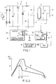
- FIG. 1 is a diagram showing the circuit configuration of a discharge lamp lighting device according to a first embodiment of this invention.
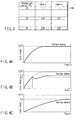
- FIG. 2 shows two load power curves in the embodiment of FIG. 1, i.e., a curve showing the relation the lamp power WL(F) and lamp voltage VL(F) have during full lighting, and a curve showing the relation the lamp power WL(d) and lamp voltage VL(d) have during 50%-dimming.
- FIG. 3 is a diagram showing a table in which values "a" and "b" corresponding to dimming light amounts in the above embodiment are set.
- FIG. 4A is a diagram showing a rise characteristic of lamp voltage at the start lighting time when the lamp is lighted in the full-lighting mode.
- FIG. 4B is a diagram showing a rise characteristic of lamp voltage at the start lighting time when the lamp is lighted in the dimming lighting mode.
- FIG. 4C is a diagram showing a comparison example and showing a rise characteristic when the start lighting control operation is not performed while the lamp is lighted in the dimming lighting mode.
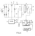
- FIG. 5 is a diagram showing the circuit configuration of a discharge lamp lighting device according to a second embodiment of this invention.
- FIG. 6 is a diagram showing the circuit configuration of a discharge lamp lighting device according to a third embodiment of this invention.
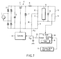
- FIG. 7 is a diagram showing the circuit configuration of a discharge lamp lighting device according to a fourth embodiment of this invention.
- FIG. 8 is a diagram showing the circuit configuration of a discharge lamp lighting device according to a fifth embodiment of this invention.
- FIG. 9 is a diagram showing the configuration of an illumination apparatus according to a sixth embodiment of this invention.
- There will now be described embodiments of this invention with reference to the accompanying drawings.
- As shown in FIG. 1, a DC power supply is formed by connecting an input terminal of a full-
wave rectifier circuit 2 to anAC power supply 1 and connecting asmoothing capacitor 3 to an output terminal of the full-wave rectifier circuit 2. - A voltage step-down
chopper circuit 4 used as a chopper circuit is connected to the DC power supply. The voltage step-downchopper circuit 4 includes aswitching element 5,inductor 6 anddiode 7. - The
switching element 5 is connected at one end to the positive terminal of the DC power supply and connected at the other end to one end of theinductor 6 and the cathode terminal of thediode 7. The anode terminal of thediode 7 is connected to the negative terminal of the DC power supply. - The positive output terminal of the voltage step-down
chopper circuit 4 is used as the other end of theinductor 6 and the negative output terminal thereof is used as the anode of thediode 7. One electrode of adischarge lamp 8 is connected to the other end of theinductor 6 and the other electrode thereof is connected to the anode terminal of thediode 7 via aresistor 9 used as a second detecting section. - A series circuit of
resistors capacitor 12 are connected in parallel between the electrodes of thedischarge lamp 8. A lamp current IL flows through theresistor 9 to generate voltage r·IL across theresistor 9. In this case, r indicates the resistance of theresistor 9. - The lamp voltage VL is generated across the series circuit of the
resistors resistors resistor 11 is set to VL/N. - Therefore, a voltage value VS1 of the voltage generated at the connection node of the
resistors resistors resistor 9. - The voltage value VS1 contains factors of the lamp voltage and lamp current and can be set to correspond to lamp power WL supplied to the
discharge lamp 8. - A lamp voltage detecting circuit configured by a series circuit of
resistors discharge lamp 8. The detected value VL of voltage obtained by dividing the lamp voltage is output from a connection node of the series circuit of theresistors resistors resistors - The voltage sep-down
chopper circuit 4 switches the switchingelement 5 according to a signal from acontroller 15. The voltage value VS1 generated at the connection node of theresistors operational amplifier 21 of thecontroller 15 via anoutput line 30 used as output means. - A dimming
signal input section 16 is supplied with a remote control signal of full lighting from the exterior to output a full-lighting signal and is supplied with a remote control signal of dimming light to output a dimming signal. The full-lighting signal and dimming signal output from the dimmingsignal input section 16 are PWM (pulse width modulation) signals, converted into DC voltage by afilter 17 and then input to a dimming input terminal of amicrocomputer 18. - The detected value VL of voltage obtained by dividing the lamp voltage output from the lamp voltage detecting circuit (
resistors 13 and 14) is input to the VL input terminal of themicrocomputer 18. The dimming input terminal and VL input terminal each have an A/D converter to convert the input voltage value into a digital value and supply the same. - The
microcomputer 18 has a table 19. In the table 19, the characteristic of a load power curve of lamp power WL(F) with respect to lamp voltage VL(F) at the full-lighting time indicated by a graph g1 in FIG. 2 is set as data. For example, when a 100W type ceramic metal halide lamp (neocera MT100 CHE) made by TOSHIBA LIGHTING & TECHNOLOGY CO. is used as thedischarge lamp 8, the load power curve g1 has a stable lighting region (flat region of the graph g1) which ensures that the rated lamp power WL is set at 100W in a range before and after the lamp voltage of 100V, that is, in a range of the lamp voltage VL of approximately 90V to 110V. In the table 19, values "a" and "b" which respectively correspond to the lamp voltage and lamp current and vary according to a dimming light amount of a dimming signal are set. The values "a" and "b" can be attained based on actual measurements when thedischarge lamp 8 is lighted in a dimming mode. - The
controller 15 andmicrocomputer 18 configure a control circuit. Thecontroller 15 compares the voltage value VS1 with a reference voltage value VS2 output from themicrocomputer 18 in theoperational amplifier 21 and controls the switching duty of theswitching element 5 of the voltage step-downchopper circuit 4 to set the compared voltage values equal to each other. By controlling the voltage step-downchopper circuit 4 by use of thecontroller 15, the voltage step-downchopper circuit 4 performs the power control operation for thedischarge lamp 8. - When an input signal to the dimming
signal input section 16 is a full-lighting signal and if themicrocomputer 18 is supplied with a detected value VL(F) of the lamp voltage from the lamp voltage detecting circuit (resistors 13, 14), themicrocomputer 18 reads out lamp power WL(F) corresponding to the lamp voltage VL(F) from the table 19. Then, it outputs an output corresponding to the lamp power WL(F) from the output terminal thereof. - The output corresponding to the lamp power WL(F) output from the output terminal of the
microcomputer 18 is supplied to theoperational amplifier 21 of thecontroller 15 via thefilter circuit 20 as the reference voltage value VS2. - Next, the operation of the discharge lamp lighting device when a dimming signal with the dimming light amount of 50% is input to the dimming input terminal of the
microcomputer 18 is explained. In this case, the dimming light amount of 50% indicates that power is adjusted to set the light output to 50% of the light output at the full-lighting time. - For example, a graph g2 of FIG. 2 shows the characteristic of a load power curve of the lamp power WL(d) with respect to lamp voltage VL(d) when the dimming light amount of the
discharge lamp 8 is set to 50%. When the dimming light amount is 50%, light flux from thedischarge lamp 8 becomes 50% of the light flux at the full-lighting time. At this time, the lamp power WL(d) of thedischarge lamp 8 is set to 60W. - The range of the lamp voltage VL(d) in the stable lighting region (flat region of the graph g2) in which the lamp power of the
discharge lamp 8 is maintained at 60W varies in a range higher and lower than 88V, that is, in a range of approximately 80V and 96V. Thus, the lamp voltage of thedischarge lamp 8 varies with a variation in the lamp power according to the dimming light amount and, as a result, the stable lighting region and lamp current also vary. - Voltage value VS1 (= VL/N + r·IL) is generated at the connection node of the
resistors resistor 9. Note that the voltage value VS1 has been obtained by adding voltage r·IL generated from the current IL flowing in theresistor 9 to the lamp voltage VL/N that is a voltage obtained by dividing VL by N by virtue of theresistors operational amplifier 21 of thecontroller 15. - When a dimming signal is input in a state where the full-lighting signal is input, the
microcomputer 18 reads out values "a" and "b" corresponding to the dimming light amount of the dimming signal from the table 19 and lights thedischarge lamp 8 in the dimming mode. - Next, the
microcomputer 18 derives lamp power WL(d) at the dimming time based on the lamp voltage VL(F) obtained at this time, lamp power WL(F) at the full-lighting time read out from the table 19 and the values "a" and "b" read out from the table 19. - As described before, since the lamp power WL(F) is the sum of the lamp voltage factor and lamp current factor, the lamp current at the full-lighting time is derived by calculating the expression of (lamp power WL(F) at full-lighting time - (lamp voltage VL(d) at dimming time)/(value "b")). Then, the lamp voltage VL(F) at the full-lighting time is also calculated.
- Therefore, the lamp power WL(d) at the dimming time is obtained by calculating the expression of (value "a" × lamp voltage VL(F) at full-lighting time + value "b" × lamp current at full-lighting time).
- At this time, the lamp power WL(d) corresponding to the dimming light amount can be derived by calculation to set the relation between the lamp voltage VL and the lamp power WL(d) at the dimming time to the characteristic of a load power curve approximately similar to the load power curve g1 at the full-lighting time.
- By considering a case where the
discharge lamp 8 is inadvertently extinguished and re-started, themicrocomputer 18 may derive the lamp power WL(d) of thedischarge lamp 8 to jump from the load power curve g1 to the load power curve g2 when the lamp voltage VL has exceeded a preset value. Then, an output corresponding to the thus derived lamp power WL(d) is supplied from the output terminal of themicrocomputer 18 to theoperational amplifier 21 of thecontroller 15 via thefilter circuit 20 as the reference voltage value VS2. - Further, when a dimming light amount is changed while a dimming signal with a certain dimming light amount is being input, the
microcomputer 18 temporarily derives a lamp voltage value VL(F) at the full-lighting time by use of a detected value VL(d1) of the lamp voltage which is so far supplied thereto from the lamp voltage detecting circuit (resistors R13, R14) and values "a1" and "b1" based on the dimming light amount obtained up to now. Then, it reads out corresponding lamp power WL(F) at the full-lighting time from the table 19 by use of the lamp voltage value VL(F) at the full-lighting time. - Further, the
microcomputer 18 reads out values "a2" and "b2" corresponding to a new changed dimming light amount from the table 19 and derives lamp power WL(d) corresponding to the new dimming light amount based on the readout values "a2" and "b2". - Also, at this time, the lamp power WL(d) corresponding to the dimming light amount is derived by calculation to set the relation between the lamp voltage VL and the lamp power WL(d) at the dimming time to the characteristic of a load power curve which is approximately similar to the load power curve g1 at the full-lighting time. Then, an output corresponding to the thus derived lamp power WL(d) is supplied from the output terminal of the
microcomputer 18 to theoperational amplifier 21 of thecontroller 15 via thefilter circuit 20 as the reference voltage value VS2. - Next, for example, a case wherein the
discharge lamp 8 which is lighted in the full-lighting mode with the lamp power WL(F) set at 100W, the lamp voltage VL(F) set at 100V and the lamp current IL(F) set 1A at the full-lighting time is changed into a dimming mode with the dimminglight amount 50% is explained. - In this example, a table 19a in which values "a" and "b" corresponding to the dimming light amount are set as shown in FIG. 3 is used as part of the table 19. In the discharge lamp lighting device used in this example, the maximum dimming light amount is set to 50% and the control operation for the dimming light amount exceeding 50% is not performed. Therefore, data set in the table 19a is set in a range of the dimming light amount of 0% to 50%.
- When a dimming signal with the dimming
light amount 50% is input, themicrocomputer 18 acquires a value "a" = 0.89 and a value "b" = 0.67 corresponding to the dimming light amount from the table 19a. Then, it derives the lamp power WL(d) at the 50%-dimming time which is approximately equal to 60W based on the lamp power WL(F) = 100W at the full-lighting time, the lamp voltage VL(F) = 100V at the full-lighting time, the value "a" = 0.89 and the value "b" = 0.67. - With the above configuration, the
microcomputer 18 reads out lamp power WL(F) corresponding to the lamp voltage VL(F) from the table 19 while a full-lighting signal is being input from the dimmingsignal input section 16 to themicrocomputer 18 via thefilter 17. Then, it supplies an output corresponding to the lamp power WL(F) from the output terminal thereof to theoperational amplifier 21 of thecontroller 15 via thefilter circuit 20 as the reference voltage value VS2. - The voltage value VS1 of (VL/N + r·IL) obtained by superimposing the voltage VL/N on the voltage r·IL generated by the lamp current IL flowing through the
resistor 9 is input from the connection node of theresistors operational amplifier 21 of thecontroller 15. - The
controller 15 compares the voltage value VS1 with the reference voltage value VS2 in theoperational amplifier 21 and controls the switching duty of theswitching element 5 of the voltage step-downchopper circuit 4 to set the voltage value VS1 equal to the reference voltage value VS2. - As a result, power supplied from the voltage step-down
chopper circuit 4 to thedischarge lamp 8 is controlled and set to power of, for example, WL(F) = 100W in the stable lighting region of the load power curve g1 at the full-lighting time. - In this state, if a dimming signal is input from the dimming
signal input section 16 to themicrocomputer 18 via thefilter 17, themicrocomputer 18 reads out lamp power WL(F) corresponding to the lamp voltage VL(F) from the table 19 and reads out values "a" and "b" corresponding to the dimming light amount of the dimming signal from the table 19a. Then, it derives lamp power WL(d) according to a load power curve similar to the load power curve g1 at the full-lighting time by using the lamp voltage VL(F), lamp power WL(F) and values "a" and "b". - The
microcomputer 18 supplies an output corresponding to the thus derived lamp power WL(d) from the output terminal thereof to theoperational amplifier 21 of thecontroller 15 via thefilter circuit 20 as the reference voltage value VS2. - The voltage value VS1 of (VL/N + r·IL) obtained by superimposing the lamp voltage VL/N on the voltage r·IL generated by the lamp current IL flowing through the
resistor 9 is input from the connection node of theresistors operational amplifier 21 of thecontroller 15. - The
controller 15 compares the voltage value VS1 with the reference voltage value VS2 in theoperational amplifier 21 and controls the switching duty of theswitching element 5 of the voltage step-downchopper circuit 4 to set the voltage value VS1 equal to the reference voltage value VS2. - As a result, power supplied from the voltage step-down
chopper circuit 4 to thedischarge lamp 8 is controlled and set to power in the stable lighting region which corresponds to the dimming light amount of the dimming signal. For example, if the dimming signal has a dimming light amount of 50%, the lighting state of thedischarge lamp 8 is controlled so that the discharge lamp will be lighted with the lamp power WL(d) set at approximately equal to 60W in a range of the lamp voltage VL(d) of approximately 80V to 96V according to the load power curve g2 similar to the load power curve g1. The brightness of thedischarge lamp 8 at this time becomes 50% of the brightness at the full-lighting time. - Thus, power supplied to the
discharge lamp 8 can be, of course, controlled according to power in the stable lighting region at the full-lighting time and can also be controlled according to power in the stable lighting region corresponding to a dimming light amount by adequately controlling the lamp voltage VL at the dimming time. - The lighting device of the present embodiment can adequately perform the lamp power control operation according to a dimming signal. In addition, it is possible to derive target lamp power WL(d) at the dimming time in a short period of time by using values "a" and "b" corresponding to a dimming light amount read out from the table 19. Therefore, the lighting device of the present embodiment can rapidly perform the lamp power control operation at the dimming time.
- Further, in the lighting device of the present embodiment, the start lighting control operation of the
discharge lamp 8 at the dimming time is performed by using the rated values like the start lighting control operation at the full-lighting time. That is, thecontroller 15 has switching means 22 for changing the output mode of thedischarge lamp 8 in a period from the starting time thereof to the lighting start time from a rated output mode to a dimming output mode. - The switching means 22 sets the output mode into a rated output mode in which the
discharge lamp 8 is started in a rated starting condition at the dimming start time to control the switching duty of theswitching element 5 of the voltage step-downchopper circuit 4. The rated starting condition is a condition that thedischarge lamp 8 is started to start the lighting operation with the rated value. - Then, when the lamp voltage of the
discharge lamp 8 has reached preset voltage, the switching means 22 switches the output mode from the rated output mode to a dimming output mode in which it starts in the dimming start condition while the power characteristic of the dimming ratio corresponding to the dimming signal is maintained. - As a result, the
controller 15 controls the switching duty of theswitching element 5 of the voltage step-downchopper circuit 4 in the dimming output mode. The dimming start condition is a condition in which thedischarge lamp 8 is started according to a dimming light amount and controlled to start the lighting operation. - That is, the
controller 15 controls the voltage step-downchopper circuit 4 to start thedischarge lamp 8 with the rated voltage and perform the lighting operation at the full-lighting time. Thus, as shown in FIG. 4A, the lamp voltage VL satisfactorily rises. The lamp voltage VL(F) shown in FIG. 4A indicates rated lamp voltage. - Further, the
controller 15 controls the voltage step-downchopper circuit 4 by use of the switching means 22 at the dimming lighting time. The switching means 22 first sets the output mode to the rated output mode in which the discharge lamp is started in the rated starting condition to start the lighting operation of thedischarge lamp 8. Then, when the lamp voltage VL has reached preset voltage VL1, it switches the output mode from the rated output mode to the dimming output mode in which the discharge lamp is started in the dimming start condition while the power characteristic according to the dimming light amount of the dimming signal is maintained. - As a result, as shown in FIG. 4B, the
discharge lamp 8 is first controlled to be lighted with the rated voltage like the case of the full-lighting operation. Then, when the lamp voltage VL has reached preset voltage VL1, the dimming lighting operation is controlled according to the load power curve corresponding to the dimming light amount of the dimming signal from the dimmingsignal input section 16. - That is, the lighting operation of the
discharge lamp 8 is controlled with lamp voltage VL2 corresponding to the dimming light amount. As a result, the lighting device of the present embodiment can perform the control operation without delaying the rise time of the lamp voltage at the dimming lighting time. Therefore, there occurs no possibility that the discharge lamp is extinguished due to delay in the rise time of the lamp voltage. - On the other hand, as shown in FIG. 4C, when the
discharge lamp 8 is not lighted with the rated voltage at the dimming lighting time, the rise characteristic of the lamp voltage becomes smooth and there occurs a possibility that the discharge lamp is extinguished due to delay in the rise time of the lamp voltage. - Further, since the lighting device of the present embodiment switches the output mode from the rated output mode to the dimming output mode with the preset voltage VL1 lower than the lamp voltage VL2 at the dimming time, there is no possibility that excessively high lamp power is applied to the
discharge lamp 8 at the rise time of the lamp voltage. - As a result, the
discharge lamp 8 can suppress damage given to the electrode to the lowest limit and suppress a variation in the brightness at the switching time from the rated output mode to the dimming output mode to the minimum. - Further, in the lighting device of the present embodiment, the
controller 15 switches the control operation of the voltage step-downchopper circuit 4 from the dimming lighting control operation to the full lighting control operation when thedischarge lamp 8 is extinguished in a state where thedischarge lamp 8 is lighted in the dimming mode. Thus, the lighting device of the present embodiment can improve the condition of starting faults due to insufficient open voltage generated at the extinguishing time and suppress damage to the lamp electrode. - In the present embodiment, a case wherein the values "a" and "b" corresponding to the dimming light amount are previously set in the table 19 is explained, but this is not limitative. For example, the values can be derived by calculation based on the dimming light amount of a dimming signal.
- In this embodiment, portions which are the same as those of the first embodiment are denoted by the same reference symbols and the detail explanation thereof is omitted.
- As shown in FIG. 5, a discharge lamp lighting device of the present embodiment directly inputs a dimming signal of a PWM (pulse width modulation) signal from a dimming
signal input section 16 to the dimming light input terminal of amicrocomputer 181 without using thefilter 17. - The
microcomputer 181 converts an input dimming signal to DC voltage in the internal portion. The other functions of themicrocomputer 181 are the same as those of themicrocomputer 18 of the first embodiment. - Also, in the discharge lamp lighting device, the
microcomputer 181 supplies a reference voltage value VS2 used to control the lighting operation of thedischarge lamp 8 with lamp power WL(F) which is power in the stable lighting region of a load power curve g1 at the input time of a full-lighting signal from the output terminal thereof to acontroller 15 via afilter circuit 20. - Further, the
microcomputer 181 supplies a reference voltage value VS2 used to control the lighting operation of thedischarge lamp 8 with lamp power WL(d) which is power in the stable lighting region of a load power curve which is similar to the load power curve g1 and derived according to values "a" and "b" corresponding to a dimming light amount at the input time of a dimming signal from the output terminal thereof to thecontroller 15 via thefilter circuit 20. - Therefore, in the present embodiment, the
controller 15 controls a voltage step-downchopper circuit 4 to light thedischarge lamp 8 with the lamp power WL(F) in the stable lighting region of the load power curve g1 at the full-lighting time. Further, at the dimming time, it controls the voltage step-downchopper circuit 4 to light thedischarge lamp 8 with the lamp power WL(d) in the stable lighting region of the load power curve which is similar to the load power curve g1 and derived according to the dimming light amount. - Thus, in the present embodiment, the same effect and operation as those of the first embodiment can be attained.
- In this embodiment, portions which are the same as those of the former embodiments are denoted by the same reference symbols and the detail explanation thereof is omitted.
- As shown in FIG. 6, a discharge lamp lighting device of the present embodiment adds a voltage value VS1 of (VL/N + r·IL) obtained by superimposing lamp voltage VL/N on voltage r·IL generated by a lamp current IL flowing through a
resistor 9 and output from a connection node ofresistors microcomputer 18 via afilter circuit 20 and supplies the thus added voltage to acontroller 151. - The
controller 151 controls the switching duty of aswitching element 5 of a voltage step-downchopper circuit 4 to set the added voltage of the voltage value VS1 and reference voltage value VS2 to preset constant voltage. The constant voltage set in thecontroller 151 is different at the full-lighting time and at the dimming time and varies according to the dimming degree at the dimming time. The other functions of thecontroller 15 are the same as those of thecontroller 15 explained in the first embodiment. - Also, in the discharge lamp lighting device, the
microcomputer 18 supplies the reference voltage value VS2 used to control the lighting operation of thedischarge lamp 8 with lamp power WL(F) which is power in the stable lighting region of the load power curve g1 at the input time of a full-lighting signal from the output terminal thereof. - Further, the
microcomputer 18 supplies the reference voltage value VS2 used to control the lighting operation of thedischarge lamp 8 with lamp power WL(d) which is power in the stable lighting region of a load power curve which is similar to the load power curve g1 and derived according to values "a" and "b" corresponding to a dimming light amount at the input time of a dimming signal from the output terminal thereof. - The reference voltage value VS2 output from the output terminal of the
microcomputer 18 is output via thefilter circuit 20 and added with the voltage value VS1 supplied from the connection node of theresistors controller 151. Thecontroller 151 controls the switching duty of theswitching element 5 of a voltage step-downchopper circuit 4 to set the added voltage of the voltage value VS1 and reference voltage value VS2 to preset constant voltage. - Also, in the discharge lamp lighting device, the
controller 151 controls the voltage step-downchopper circuit 4 to light thedischarge lamp 8 with the lamp power WL(F) in the stable lighting region of the load power curve g1 at the full-lighting time. Further, at the dimming time, it controls the voltage step-downchopper circuit 4 to light thedischarge lamp 8 with the lamp power WL(d) in the stable lighting region of the load power curve which is similar to the load power curve g1 and derived according to the dimming light amount. - Thus, in the present embodiment, the same effect and operation as those of the first embodiment can be attained.
- In this embodiment, portions which are the same as those of the former embodiments are denoted by the same reference symbols and the detail explanation thereof is omitted.
- As shown in FIG. 7, a discharge lamp lighting device of the present embodiment directly inputs a dimming signal of a PWM (pulse width modulation) signal from a dimming
signal input section 16 to the dimming light input terminal of amicrocomputer 181 without using thefilter 17. - Like the second embodiment, the
microcomputer 181 converts an input dimming signal to DC voltage in the internal portion. - Further, the discharge lamp lighting device of the present embodiment adds a voltage value VS1 of (VL/N + r·IL) obtained by superimposing lamp voltage VL/N on voltage r·IL generated by a lamp current IL flowing through a
resistor 9 and output from a connection node ofresistors microcomputer 181 via afilter circuit 20 and supplies the thus added voltage to acontroller 151. - Like the case of the third embodiment, the
controller 151 controls the switching duty of aswitching element 5 of a voltage step-downchopper circuit 4 to set the added voltage of the voltage value VS1 and reference voltage value VS2 to preset constant voltage. - Also, in the discharge lamp lighting device, the
microcomputer 181 supplies the reference voltage value VS2 used to control the lighting operation of thedischarge lamp 8 with lamp power WL(F) which is power in the stable lighting region of a load power curve g1 at the input time of a full-lighting signal from the output terminal thereof. - Further, the
microcomputer 181 supplies the reference voltage value VS2 used to control the lighting operation of thedischarge lamp 8 with lamp power WL(d) which is power in the stable lighting region of a load power curve which is similar to the load power curve g1 and derived according to values "a" and "b" corresponding to a dimming light amount at the input time of a dimming signal from the output terminal thereof. - The reference voltage value VS2 output from the output terminal of the
microcomputer 181 is output via thefilter circuit 20 and added with the voltage value VS1 from the connection node of theresistors controller 151. Thecontroller 151 controls the switching duty of theswitching element 5 of the voltage step-downchopper circuit 4 to set the added voltage of the voltage value VS1 and reference voltage value VS2 to preset constant voltage. - Also, in the discharge lamp lighting device, the
controller 151 controls the voltage step-downchopper circuit 4 to light thedischarge lamp 8 with the lamp power WL(F) in the stable lighting region of the load power curve g1 at the full-lighting time. Further, at the dimming time, it controls the voltage step-downchopper circuit 4 to light thedischarge lamp 8 with the lamp power WL(d) in the stable lighting region of the load power curve which is similar to the load power curve g1 and derived according to the dimming light amount. - Thus, in the present embodiment, the same effect and operation as those of the first embodiment can be attained.
- In the present embodiment, a discharge lamp lighting device which AC-lights a
discharge lamp 8 by using a polarity inverting circuit is explained. Portions which are the same as those of the former embodiments are denoted by the same reference symbols and the detail explanation thereof is omitted. - As shown in FIG. 8, the discharge lamp lighting device of the present embodiment includes a
diode 7 having a cathode terminal connected to one end of aninductor 6 and an anode terminal connected to one end of aresistor 9. A series circuit ofresistors capacitor 12 are connected between the other end of theinductor 6 and the other end of theresistor 9. - The discharge lamp lighting device of the present embodiment has a
polarity inverting circuit 23 connected to the series circuit of theresistors polarity inverting circuit 23 includes a series circuit of a pair of switchingelements elements - The
polarity inverting circuit 23 has a series circuit of anigniter 28 which generates a high-voltage pulse at the starting time and thedischarge lamp 8 connected between a connection node of the pair of switchingelements elements - A voltage value VS1 generated from the connection node of the
resistors operational amplifier 21 of acontroller 15 via anoutput line 30 and a VL input terminal of amicrocomputer 18. Themicrocomputer 18 derives a detected value VL of lamp voltage from the voltage value VS1 input to the VL input terminal and performs the same process as described in the former embodiments by using the detected value VL. - The switching
elements polarity inverting circuit 23 are switching-driven by adrive circuit 29. At the lighting time, thepolarity inverting circuit 23 sets the switchingelements drive circuit 29 and sets the switchingelements discharge lamp 8 in a direction indicated by an arrow A of solid lines in FIG. 8. Then, in a next half cycle, it sets the switchingelements drive circuit 29 and sets the switchingelements discharge lamp 8 in a direction indicated by an arrow B of dotted lines in FIG. 8. Thus, the lighting device of the present embodiment AC-lights thedischarge lamp 8. - Also, in the discharge lamp lighting device, the
microcomputer 18 supplies a reference voltage value VS2 used to control the lighting operation of thedischarge lamp 8 with lamp power WL(F) which is power in the stable lighting region of a load power curve g1 from the output terminal thereof to the controller via afilter circuit 20 at the input time of a full-lighting signal. - Further, at the input time of a dimming signal, the
microcomputer 18 supplies a reference voltage value VS2 used to control the lighting operation of thedischarge lamp 8 with lamp power WL(d) which is power in the stable lighting region of a load power curve which is similar to the load power curve g1 and derived by using values "a" and "b" corresponding to a dimming light amount from the output terminal thereof to thecontroller 15 via thefilter circuit 20. - Therefore, also, in the present embodiment, the
controller 15 controls a voltage step-downchopper circuit 4 to light thedischarge lamp 8 with the lamp power WL(F) in the stable lighting region of the load power curve g1 at the full-lighting time. Further, at the dimming time, it controls the voltage step-downchopper circuit 4 to light thedischarge lamp 8 with the lamp power WL(d) in the stable lighting region of the load power curve which is similar to the load power curve g1 and derived according to the dimming light amount. - Thus, in the present embodiment, the same effect and operation as those of the first embodiment can be attained.
- In the present embodiment, an illumination apparatus using one of the discharge lamp lighting devices which are explained in the first to fifth embodiments is explained.
- As shown in FIG. 9, the illumination apparatus has a discharge
lamp lighting device 100 and illumination apparatusmain body 101 which are separately arranged. The illumination apparatusmain body 101 includes a concave-shapedshade portion 101a having an inner surface formed of a reflection surface and adischarge lamp 102 is loaded on the central portion of theshade portion 101a. The dischargelamp lighting device 100 has the same configuration as that of one of the discharge lamp lighting devices described in the first to fourth embodiments. - The discharge
lamp lighting device 100 used in the above illumination apparatus lights thedischarge lamp 102 with lamp power WL(F) in the stable lighting region of a load power curve g1 at the full-lighting time. Further, at the dimming time, it lights thedischarge lamp 102 with lamp power WL(d) in the stable lighting region of a load power curve which is similar to the load power curve g1 and derived according to the dimming light amount. - Thus, power supplied to the
discharge lamp 102 is controlled by use of power in the stable lighting region at the full-lighting time and is also controlled by use of power in the stable lighting region corresponding to the dimming light amount by adequately controlling lamp voltage VL at the dimming time. Further, at the dimming time, target lamp power can be derived by use of values "a" and "b" corresponding to the dimming light amount read out from a table in a short period of time and, as a result, the lamp power control operation can be rapidly performed.
Claims (4)
- A discharge lamp lighting device having a dimming signal input section (16) to which a full-lighting signal and dimming signal are input, a chopper circuit (4) which adjusts power supplied to a discharge lamp (8) and a lamp voltage detecting circuit (13, 14) which detects lamp voltage applied to the discharge lamp (8), characterized by comprising:a control circuit (15, 18) which controls an output of the chopper circuit (4) according to a dimming signal and lamp voltage to control power of the discharge lamp (8),
wherein the control circuit (15, 18) includes means (18) for setting a reference voltage value according to one of a full-lighting signal and dimming signal from the dimming signal input section (16) and lamp voltage detected by the lamp voltage detecting circuit (13, 14), a first detecting section (10, 11) which is connected in parallel with the discharge lamp (8) and detects voltage corresponding to lamp voltage, a second detecting section (9) which is connected in series with the discharge lamp (8) and detects voltage corresponding to a lamp current, output means (30) for outputting voltage equal to the sum of voltages detected by the detecting sections (9; 10, 11) and output control means (15) for controlling an output of the chopper circuit (4) to set the sum voltage value output from the output means (30) equal to the reference voltage value, and the discharge lamp is set to have a stable lighting region in which rated lamp power at each of full-light lighting time and dimming lighting time is ensured according to a lamp voltage region of preset width at each of full-lighting time and dimming time. - The discharge lamp lighting device according to claim 1, characterized in that the control circuit (15, 18) is previously set to have a load power curve having a stable lighting region with respect to the discharge lamp (8) based on the lamp voltage at the full-lighting time detected by the lamp voltage detecting circuit (13, 14), and means (18) for setting the reference voltage value is set to have a table (19) in which values "a" corresponding to lamp voltages which correspond to dimming light amounts and values "b" corresponding to lamp currents which correspond to dimming light amounts are set, sets a reference voltage value by use of lamp voltage detected by the lamp voltage detecting circuit (13, 14) and corresponding ones of the values "a" and "b" in the table (19) based on inputting of a dimming signal and sets a load power curve similar to the load power curve at the full-lighting time in a dimming mode.
- The discharge lamp lighting device according to one of claims 1 and 2, characterized in that the control circuit (15, 18) includes switching means (22) for setting an output mode to a rated output mode in which the discharge lamp is started in a rated starting condition at dimming start time and switching the output mode from the rated output mode to a dimming output mode in which the discharge lamp is started in a dimming start condition while a power characteristic corresponding to a dimming light amount of the dimming signal is maintained when the lamp voltage of the discharge lamp (8) has reached preset voltage.
- An illumination apparatus having a discharge lamp, characterized by comprising:a discharge lamp lighting device (100) described in one of claims 1 to 3, andan illumination main body (101) having the discharge lamp (102) mounted thereon.
Applications Claiming Priority (3)
| Application Number | Priority Date | Filing Date | Title |
|---|---|---|---|
| JP2005283745 | 2005-09-29 | ||
| JP2005338754 | 2005-11-24 | ||
| JP2006224985A JP4923852B2 (en) | 2005-09-29 | 2006-08-22 | Discharge lamp lighting device and lighting device |
Publications (1)
| Publication Number | Publication Date |
|---|---|
| EP1773104A1 true EP1773104A1 (en) | 2007-04-11 |
Family
ID=37646620
Family Applications (1)
| Application Number | Title | Priority Date | Filing Date |
|---|---|---|---|
| EP06255050A Withdrawn EP1773104A1 (en) | 2005-09-29 | 2006-09-29 | Discharge lamp lighting device and illumination apparatus |
Country Status (2)
| Country | Link |
|---|---|
| EP (1) | EP1773104A1 (en) |
| JP (1) | JP4923852B2 (en) |
Citations (8)
| Publication number | Priority date | Publication date | Assignee | Title |
|---|---|---|---|---|
| US4240009A (en) * | 1978-02-27 | 1980-12-16 | Paul Jon D | Electronic ballast |
| US4412154A (en) * | 1981-05-20 | 1983-10-25 | Compagnie De Signaux Et D'entreprises Electriques | Start up frequency adjustment in an electronic power device for a discharge lamp |
| EP0445882A2 (en) * | 1990-03-08 | 1991-09-11 | Koninklijke Philips Electronics N.V. | Switching arrangement |
| US5103143A (en) * | 1990-05-14 | 1992-04-07 | Hella Kg Hueck & Co. | Process and apparatus for starting a high pressure gas discharge lamp for vehicles |
| US5198728A (en) * | 1991-01-24 | 1993-03-30 | Patent-Treuhand Gesellschaft Fur Fur Elektrische Gluhlampen Mbh | Operating circuit for a discharge lamp |
| US5212428A (en) * | 1990-10-01 | 1993-05-18 | Koito Manufacturing Co., Ltd. | Lighting circuit for vehicular discharge lamp |
| US20030122505A1 (en) * | 2002-01-02 | 2003-07-03 | Ptent-Treuhand-Gesellschaft Fur Elektrisch Gluhlampen Mbh | Operating appliance and an operating method for high-pressure lamps |
| EP1365634A2 (en) * | 2002-05-15 | 2003-11-26 | Ushiodenki Kabushiki Kaisha | Light source device |
Family Cites Families (3)
| Publication number | Priority date | Publication date | Assignee | Title |
|---|---|---|---|---|
| JPH07320888A (en) * | 1994-05-26 | 1995-12-08 | Tec Corp | Lighting device for electric discharge lamp |
| JPH08273871A (en) * | 1995-03-31 | 1996-10-18 | Toshiba Lighting & Technol Corp | Power supply unit, high pressure discharge lamp lighting device, and lighting system |
| JPH11233282A (en) * | 1998-02-13 | 1999-08-27 | Toshiba Lighting & Technology Corp | Discharge lamp lighting device, lighting system and projector |
-
2006
- 2006-08-22 JP JP2006224985A patent/JP4923852B2/en not_active Expired - Fee Related
- 2006-09-29 EP EP06255050A patent/EP1773104A1/en not_active Withdrawn
Patent Citations (8)
| Publication number | Priority date | Publication date | Assignee | Title |
|---|---|---|---|---|
| US4240009A (en) * | 1978-02-27 | 1980-12-16 | Paul Jon D | Electronic ballast |
| US4412154A (en) * | 1981-05-20 | 1983-10-25 | Compagnie De Signaux Et D'entreprises Electriques | Start up frequency adjustment in an electronic power device for a discharge lamp |
| EP0445882A2 (en) * | 1990-03-08 | 1991-09-11 | Koninklijke Philips Electronics N.V. | Switching arrangement |
| US5103143A (en) * | 1990-05-14 | 1992-04-07 | Hella Kg Hueck & Co. | Process and apparatus for starting a high pressure gas discharge lamp for vehicles |
| US5212428A (en) * | 1990-10-01 | 1993-05-18 | Koito Manufacturing Co., Ltd. | Lighting circuit for vehicular discharge lamp |
| US5198728A (en) * | 1991-01-24 | 1993-03-30 | Patent-Treuhand Gesellschaft Fur Fur Elektrische Gluhlampen Mbh | Operating circuit for a discharge lamp |
| US20030122505A1 (en) * | 2002-01-02 | 2003-07-03 | Ptent-Treuhand-Gesellschaft Fur Elektrisch Gluhlampen Mbh | Operating appliance and an operating method for high-pressure lamps |
| EP1365634A2 (en) * | 2002-05-15 | 2003-11-26 | Ushiodenki Kabushiki Kaisha | Light source device |
Also Published As
| Publication number | Publication date |
|---|---|
| JP2007173204A (en) | 2007-07-05 |
| JP4923852B2 (en) | 2012-04-25 |
Similar Documents
| Publication | Publication Date | Title |
|---|---|---|
| JP3882156B2 (en) | Discharge lamp lighting device | |
| JP5462853B2 (en) | Drive circuit system for gas discharge lamp and control method thereof | |
| JP4348984B2 (en) | High pressure discharge lamp lighting device | |
| US7084585B2 (en) | Discharge lamp lighting apparatus | |
| JP2008270095A (en) | Discharge lamp lighting device, lighting fixture, and illumination system | |
| JP4534438B2 (en) | Discharge lamp lighting device | |
| KR20100047306A (en) | Electronic ballast and method for operating at least one discharge lamp | |
| JP2009272255A (en) | Discharge lamp lighting device, lighting device | |
| JP5069573B2 (en) | High pressure discharge lamp lighting device, lighting fixture | |
| EP1773104A1 (en) | Discharge lamp lighting device and illumination apparatus | |
| JP5163892B2 (en) | Discharge lamp lighting device | |
| JPH11339993A (en) | Discharge lamp lighting device | |
| JPH11262256A (en) | Power unit and electric discharge lamp turning-on device | |
| JP2009289664A (en) | Lighting device for discharge lamp, and illumination apparatus | |
| JP4475072B2 (en) | Discharge lamp lighting device and lighting apparatus using the same | |
| JP4339568B2 (en) | Lighting device | |
| JP4036145B2 (en) | Discharge lamp lighting device | |
| JP2003031385A (en) | Discharge lamp lighting device | |
| JP4413479B2 (en) | Discharge lamp lighting device | |
| JP4475073B2 (en) | Discharge lamp lighting device and lighting apparatus using the same | |
| JP4096532B2 (en) | Discharge lamp lighting device | |
| JP2005086915A (en) | Power supply device, discharge lamp lighting device, and lighting equipment | |
| JP4036240B2 (en) | Discharge lamp lighting device | |
| JP5712359B2 (en) | Discharge lamp lighting device and lighting fixture equipped with discharge lamp lighting device | |
| JP2004303688A (en) | Discharge lamp lighting device |
Legal Events
| Date | Code | Title | Description |
|---|---|---|---|
| PUAI | Public reference made under article 153(3) epc to a published international application that has entered the european phase |
Free format text: ORIGINAL CODE: 0009012 |
|
| AK | Designated contracting states |
Kind code of ref document: A1 Designated state(s): AT BE BG CH CY CZ DE DK EE ES FI FR GB GR HU IE IS IT LI LT LU LV MC NL PL PT RO SE SI SK TR |
|
| AX | Request for extension of the european patent |
Extension state: AL BA HR MK YU |
|
| 17P | Request for examination filed |
Effective date: 20070817 |
|
| 17Q | First examination report despatched |
Effective date: 20070924 |
|
| AKX | Designation fees paid |
Designated state(s): AT BE BG CH CY CZ DE DK EE ES FI FR GB GR HU IE IS IT LI LT LU LV MC NL PL PT RO SE SI SK TR |
|
| STAA | Information on the status of an ep patent application or granted ep patent |
Free format text: STATUS: THE APPLICATION IS DEEMED TO BE WITHDRAWN |
|
| 18D | Application deemed to be withdrawn |
Effective date: 20110331 |
|
| R18D | Application deemed to be withdrawn (corrected) |
Effective date: 20110401 |