EP1773566B1 - Method of fabricating an implantable medical device with biaxially oriented polymers - Google Patents
Method of fabricating an implantable medical device with biaxially oriented polymers Download PDFInfo
- Publication number
- EP1773566B1 EP1773566B1 EP05773427.9A EP05773427A EP1773566B1 EP 1773566 B1 EP1773566 B1 EP 1773566B1 EP 05773427 A EP05773427 A EP 05773427A EP 1773566 B1 EP1773566 B1 EP 1773566B1
- Authority
- EP
- European Patent Office
- Prior art keywords
- polymer
- annular
- tube
- film
- annular member
- Prior art date
- Legal status (The legal status is an assumption and is not a legal conclusion. Google has not performed a legal analysis and makes no representation as to the accuracy of the status listed.)
- Not-in-force
Links
Images


Classifications
-
- B—PERFORMING OPERATIONS; TRANSPORTING
- B29—WORKING OF PLASTICS; WORKING OF SUBSTANCES IN A PLASTIC STATE IN GENERAL
- B29C—SHAPING OR JOINING OF PLASTICS; SHAPING OF MATERIAL IN A PLASTIC STATE, NOT OTHERWISE PROVIDED FOR; AFTER-TREATMENT OF THE SHAPED PRODUCTS, e.g. REPAIRING
- B29C48/00—Extrusion moulding, i.e. expressing the moulding material through a die or nozzle which imparts the desired form; Apparatus therefor
- B29C48/25—Component parts, details or accessories; Auxiliary operations
- B29C48/30—Extrusion nozzles or dies
- B29C48/32—Extrusion nozzles or dies with annular openings, e.g. for forming tubular articles
- B29C48/33—Extrusion nozzles or dies with annular openings, e.g. for forming tubular articles with parts rotatable relative to each other
-
- A—HUMAN NECESSITIES
- A61—MEDICAL OR VETERINARY SCIENCE; HYGIENE
- A61F—FILTERS IMPLANTABLE INTO BLOOD VESSELS; PROSTHESES; DEVICES PROVIDING PATENCY TO, OR PREVENTING COLLAPSING OF, TUBULAR STRUCTURES OF THE BODY, e.g. STENTS; ORTHOPAEDIC, NURSING OR CONTRACEPTIVE DEVICES; FOMENTATION; TREATMENT OR PROTECTION OF EYES OR EARS; BANDAGES, DRESSINGS OR ABSORBENT PADS; FIRST-AID KITS
- A61F2/00—Filters implantable into blood vessels; Prostheses, i.e. artificial substitutes or replacements for parts of the body; Appliances for connecting them with the body; Devices providing patency to, or preventing collapsing of, tubular structures of the body, e.g. stents
- A61F2/82—Devices providing patency to, or preventing collapsing of, tubular structures of the body, e.g. stents
-
- A—HUMAN NECESSITIES
- A61—MEDICAL OR VETERINARY SCIENCE; HYGIENE
- A61L—METHODS OR APPARATUS FOR STERILISING MATERIALS OR OBJECTS IN GENERAL; DISINFECTION, STERILISATION OR DEODORISATION OF AIR; CHEMICAL ASPECTS OF BANDAGES, DRESSINGS, ABSORBENT PADS OR SURGICAL ARTICLES; MATERIALS FOR BANDAGES, DRESSINGS, ABSORBENT PADS OR SURGICAL ARTICLES
- A61L31/00—Materials for other surgical articles, e.g. stents, stent-grafts, shunts, surgical drapes, guide wires, materials for adhesion prevention, occluding devices, surgical gloves, tissue fixation devices
- A61L31/14—Materials characterised by their function or physical properties, e.g. injectable or lubricating compositions, shape-memory materials, surface modified materials
- A61L31/148—Materials at least partially resorbable by the body
-
- A—HUMAN NECESSITIES
- A61—MEDICAL OR VETERINARY SCIENCE; HYGIENE
- A61F—FILTERS IMPLANTABLE INTO BLOOD VESSELS; PROSTHESES; DEVICES PROVIDING PATENCY TO, OR PREVENTING COLLAPSING OF, TUBULAR STRUCTURES OF THE BODY, e.g. STENTS; ORTHOPAEDIC, NURSING OR CONTRACEPTIVE DEVICES; FOMENTATION; TREATMENT OR PROTECTION OF EYES OR EARS; BANDAGES, DRESSINGS OR ABSORBENT PADS; FIRST-AID KITS
- A61F2/00—Filters implantable into blood vessels; Prostheses, i.e. artificial substitutes or replacements for parts of the body; Appliances for connecting them with the body; Devices providing patency to, or preventing collapsing of, tubular structures of the body, e.g. stents
- A61F2/82—Devices providing patency to, or preventing collapsing of, tubular structures of the body, e.g. stents
- A61F2/86—Stents in a form characterised by the wire-like elements; Stents in the form characterised by a net-like or mesh-like structure
- A61F2/90—Stents in a form characterised by the wire-like elements; Stents in the form characterised by a net-like or mesh-like structure characterised by a net-like or mesh-like structure
- A61F2/91—Stents in a form characterised by the wire-like elements; Stents in the form characterised by a net-like or mesh-like structure characterised by a net-like or mesh-like structure made from perforated sheet material or tubes, e.g. perforated by laser cuts or etched holes
-
- A—HUMAN NECESSITIES
- A61—MEDICAL OR VETERINARY SCIENCE; HYGIENE
- A61F—FILTERS IMPLANTABLE INTO BLOOD VESSELS; PROSTHESES; DEVICES PROVIDING PATENCY TO, OR PREVENTING COLLAPSING OF, TUBULAR STRUCTURES OF THE BODY, e.g. STENTS; ORTHOPAEDIC, NURSING OR CONTRACEPTIVE DEVICES; FOMENTATION; TREATMENT OR PROTECTION OF EYES OR EARS; BANDAGES, DRESSINGS OR ABSORBENT PADS; FIRST-AID KITS
- A61F2/00—Filters implantable into blood vessels; Prostheses, i.e. artificial substitutes or replacements for parts of the body; Appliances for connecting them with the body; Devices providing patency to, or preventing collapsing of, tubular structures of the body, e.g. stents
- A61F2/82—Devices providing patency to, or preventing collapsing of, tubular structures of the body, e.g. stents
- A61F2002/825—Devices providing patency to, or preventing collapsing of, tubular structures of the body, e.g. stents having longitudinal struts
-
- B—PERFORMING OPERATIONS; TRANSPORTING
- B23—MACHINE TOOLS; METAL-WORKING NOT OTHERWISE PROVIDED FOR
- B23K—SOLDERING OR UNSOLDERING; WELDING; CLADDING OR PLATING BY SOLDERING OR WELDING; CUTTING BY APPLYING HEAT LOCALLY, e.g. FLAME CUTTING; WORKING BY LASER BEAM
- B23K2103/00—Materials to be soldered, welded or cut
- B23K2103/30—Organic material
- B23K2103/42—Plastics
-
- B—PERFORMING OPERATIONS; TRANSPORTING
- B23—MACHINE TOOLS; METAL-WORKING NOT OTHERWISE PROVIDED FOR
- B23K—SOLDERING OR UNSOLDERING; WELDING; CLADDING OR PLATING BY SOLDERING OR WELDING; CUTTING BY APPLYING HEAT LOCALLY, e.g. FLAME CUTTING; WORKING BY LASER BEAM
- B23K2103/00—Materials to be soldered, welded or cut
- B23K2103/50—Inorganic material, e.g. metals, not provided for in B23K2103/02 – B23K2103/26
-
- B—PERFORMING OPERATIONS; TRANSPORTING
- B29—WORKING OF PLASTICS; WORKING OF SUBSTANCES IN A PLASTIC STATE IN GENERAL
- B29C—SHAPING OR JOINING OF PLASTICS; SHAPING OF MATERIAL IN A PLASTIC STATE, NOT OTHERWISE PROVIDED FOR; AFTER-TREATMENT OF THE SHAPED PRODUCTS, e.g. REPAIRING
- B29C48/00—Extrusion moulding, i.e. expressing the moulding material through a die or nozzle which imparts the desired form; Apparatus therefor
- B29C48/001—Combinations of extrusion moulding with other shaping operations
- B29C48/0018—Combinations of extrusion moulding with other shaping operations combined with shaping by orienting, stretching or shrinking, e.g. film blowing
-
- B—PERFORMING OPERATIONS; TRANSPORTING
- B29—WORKING OF PLASTICS; WORKING OF SUBSTANCES IN A PLASTIC STATE IN GENERAL
- B29C—SHAPING OR JOINING OF PLASTICS; SHAPING OF MATERIAL IN A PLASTIC STATE, NOT OTHERWISE PROVIDED FOR; AFTER-TREATMENT OF THE SHAPED PRODUCTS, e.g. REPAIRING
- B29C48/00—Extrusion moulding, i.e. expressing the moulding material through a die or nozzle which imparts the desired form; Apparatus therefor
- B29C48/03—Extrusion moulding, i.e. expressing the moulding material through a die or nozzle which imparts the desired form; Apparatus therefor characterised by the shape of the extruded material at extrusion
- B29C48/09—Articles with cross-sections having partially or fully enclosed cavities, e.g. pipes or channels
-
- B—PERFORMING OPERATIONS; TRANSPORTING
- B29—WORKING OF PLASTICS; WORKING OF SUBSTANCES IN A PLASTIC STATE IN GENERAL
- B29C—SHAPING OR JOINING OF PLASTICS; SHAPING OF MATERIAL IN A PLASTIC STATE, NOT OTHERWISE PROVIDED FOR; AFTER-TREATMENT OF THE SHAPED PRODUCTS, e.g. REPAIRING
- B29C49/00—Blow-moulding, i.e. blowing a preform or parison to a desired shape within a mould; Apparatus therefor
- B29C49/42—Component parts, details or accessories; Auxiliary operations
- B29C49/78—Measuring, controlling or regulating
- B29C49/786—Temperature
-
- B—PERFORMING OPERATIONS; TRANSPORTING
- B29—WORKING OF PLASTICS; WORKING OF SUBSTANCES IN A PLASTIC STATE IN GENERAL
- B29L—INDEXING SCHEME ASSOCIATED WITH SUBCLASS B29C, RELATING TO PARTICULAR ARTICLES
- B29L2031/00—Other particular articles
- B29L2031/753—Medical equipment; Accessories therefor
- B29L2031/7532—Artificial members, protheses
- B29L2031/7534—Cardiovascular protheses
Definitions
- This invention relates to methods of fabricating implantable medical devices such as stents, according to claim 1.
- This invention relates to radially expandable endoprostheses which are adapted to be implanted in a bodily lumen.
- An "endoprosthesis” corresponds to an artificial implantable medical device that is placed inside the body.
- a “lumen” refers to a cavity of tubular organ such as a blood vessel.
- a stent is an example of these endoprostheses.
- Stents are generally cylindrically shaped devices which function to hold open and sometimes expand a segment of a blood vessel or other anatomical lumen such as urinary tracts and bile ducts. Stents are often used in the treatment of atherosclerotic stenosis in blood vessels.
- Steps refers to a narrowing or constriction of the diameter of a bodily passage or orifice. In such treatments, stents reinforce body vessels and prevent restenosis following angioplasty in the vascular system.
- Restenosis refers to the reoccurrence of stenosis in a blood vessel or heart valve after it has been treated (as by balloon angioplasty or valvuloplasty) with apparent success.
- Stents have been made of many materials including metals and polymers.
- Polymer materials include both nonbioerodable and bioerodable plastic materials.
- the cylindrical structure of stents is typically composed of a scaffolding that includes a pattern or network of interconnecting structural elements or struts.
- the scaffolding can be formed from wires, tubes, or planar films of material rolled into a cylindrical shape.
- a medicated stent may be fabricated by coating the surface of either a metallic or polymeric scaffolding with a polymeric carrier.
- the polymeric carrier can include an active agent or drug.
- the pattern that makes up the stent allows the stent to be radially expandable and longitudinally flexible.
- the pattern should be designed to maintain the longitudinal flexibility and rigidity required of the stent.
- a stent should also have adequate strength in the circumferential direction.
- a number of techniques have been suggested for the fabrication of stents from tubes and planar films or sheets.
- One such technique involves laser cutting or etching a pattern onto a material. Laser cutting may be performed on a planar film of a material which is then rolled into a tube. Alternatively, a desired pattern may be etched directly onto a tube. Other techniques involve cutting a desired pattern into a sheet or a tube via chemical etching or electrical discharge machining. Laser cutting of stents has been described in a number of publications including U.S. Pat. No. 5,780,807 to Saunders , U.S. Pat. No. 5,922,005 to Richter and U.S. Pat. No. 5,906,759 to Richter .
- a treatment involving a stent involves both delivery and deployment of the stent.
- Delivery refers to introducing and transporting the stent through a bodily lumen to a region requiring treatment.
- Delivery and deployment of a stent are accomplished by positioning the stent about one end of a catheter, inserting the end of the catheter through the skin into a bodily lumen, advancing the catheter in the bodily lumen to a desired treatment location, expanding the stent at the treatment location, and removing the catheter from the lumen.
- the stent is mounted about a balloon disposed on the catheter.
- Mounting the stent typically involves compressing or crimping the stent onto the balloon.
- the stent is then expanded by inflating the balloon.
- the balloon may then be deflated and the catheter withdrawn.
- the stent may be secured to the catheter via a retractable sheath or a sock. When the stent is in a desired bodily location, the sheath may be withdrawn allowing the stent to self-expand.
- a stent it is desirable for a stent to have certain mechanical properties to facilitate delivery and deployment of the stent. For example, longitudinal flexibility is important for successful delivery of the stent. In addition, circumferential strength and rigidity and are vital characteristics in deployment and for holding open a body lumen. As indicated above, the pattern of the stent may be designed to provide longitudinal flexibility and rigidity.
- stents fabricated from polymers are that they tend to possess greater flexibility than metal stents.
- Other potential shortcomings of metal stents include adverse reactions from the body, nonbioerodability, and non-optimal drug-delivery.
- a potential shortcoming of polymer stents compared to metal stents is that polymer stents typically have less circumferential strength and rigidity. Inadequete circumferential strength potentially contributes to relatively high recoil of polymer stents after implantation into vessels.
- struts can crack during crimping, especially for brittle polymers.
- US 2003/0187158 relates to polyolefins and in particular to polyolefins comprising a C 3 -C 20 monomer and having a molecular weight of at least 700 kg/mol preferably 1000 kg/mol. There is also described a hafnium based metallocene catalyst and a process for making such polyolefins.
- Articles made according to the disclosure may take the form of articles which are intended to be used in contact with or in proximity to the body of a living being. Such articles may be disposable or intended for multiple or prolonged use.
- Such articles include but are not limited to catheters, tubing, drainage systems, syringes, grafts, prosthetics, body implants, instrumentation, support means, toothbrushes, bed covers, stents, gaskets, pump diaphragms, baby bottle nipples, pacifiers, and the like.
- a desired pattern may be cut into a stent preform by impinging a laser beam onto the stent preform.
- the laser beam is formed using a laser system comprising a resonator cavity for resonating laser radiation, a gain medium contained in the resonator cavity, a pump for periodically pumping the gain medium and an electro-optical modulator in communication with the resonator cavity.
- the laser system produces a radiation pulse for each pump period.
- Each radiation pulse is conditioned by suppressing at least a portion of the pulse.
- the pulse may also be modulated with an electro-optical modulator to produce a pulse train of ordered pulses of radiation.
- Each pulse train is output from the optical cavity as an output laser beam which is directed at the stent preform to cut a desired pattern in the stent preform.
- the present invention is directed to methods for fabricating an implantable medical device, such as a stent, from a tube, with desirable mechanical properties, such as improved circumferential strength and rigidity. Improved circumferential strength and rigidity may be obtained by inducing circumferential molecular orientation in materials for use in manufacturing an implantable medical device.
- Various embodiments of the present invention include methods for inducing circumferential molecular orientation in a material.
- a method of manufacturing an implantable medical device comprising: introducing a polymer into a forming apparatus comprising a first annular member disposed within a second annular member, wherein the polymer is conveyed through an annular chamber as an annular film between the annular members; inducing circumferential flow in the annular film; forming a tube from the annular film; and fabricating an implantable medical device from the tube, wherein the circumferential flow is induced in the annular film by rotating the tube, and the tube is rotated by positioning the tube over or within a third annular member that is configured to rotate the tube.
- Stress refers to force per unit area, as in the force acting through a small area within a plane. Stress can be divided into components, normal and parallel to the plane, called normal stress and shear stress, respectively. True stress denotes the stress where force and area are measured at the same time. Conventional stress, as applied to tension and compression tests, is force divided by the original gauge length.
- elastic deformation refers to deformation of an object in which the applied stress is small enough so that the object retains its original dimensions or essentially its original dimensions once the stress is released.
- Elastic limit refers to the maximum stress that a material will withstand without permanent deformation.
- plastic deformation refers to permanent deformation that occurs in a material under stress after elastic limits have been exceeded.
- “Strength” refers to the maximum stress along an axis in testing which a material will withstand prior to fracture. The ultimate strength is calculated from the maximum load applied during the test divided by the original cross-sectional area.
- Modulus may be defined as the ratio of the stress or force per unit area applied to a material divided by the amount of strain resulting from the applied force.
- Stress refers to the amount of elongation or compression that occurs in a material at a given stress or load.
- Elongation may be defined as the increase in length which occurs when subjected to stress. It is typically expressed as a percentage of the original length.
- solvent is defined as a substance capable of dissolving or dispersing one or more other substances or capable of at least partially dissolving or dispersing the substance(s) to form a uniformly dispersed mixture at the molecular- or ionic-size level.
- the solvent should be capable of dissolving at least 0.1 mg of the polymer in 1 ml of the solvent, and more narrowly 0.5 mg in 1 ml at ambient temperature and ambient pressure.
- a second fluid can act as a non-solvent for the impurity.
- Non-solvent is defined as a substance incapable of dissolving the other substance. The non-solvent should be capable of dissolving only less than 0.1 mg of the polymer in 1 ml of the non-solvent at ambient temperature and ambient pressure, and more narrowly only less than 0.05 mg in 1 ml at ambient temperature and ambient pressure.
- Implantable medical device is intended to include self-expandable stents, balloon-expandable stents, stent-grafts, and grafts.
- the structural pattern of the device can be of virtually any design.
- the device can also be made partially or completely from a biodegradable, bioabsorbable, or biostable polymer. The polymer may be purified to remove undesirable materials.
- Polymers can be biostable, bioabsorbable, biodegradable or bioerodable.
- Biostable refers to polymers that are not biodegradable.
- biodegradable, bioabsorbable, and bioerodable are used interchangeably and refer to polymers that are capable of being completely degraded and/or eroded when exposed to bodily fluids such as blood and can be gradually resorbed, absorbed and/or eliminated by the body.
- the processes of breaking down and eventual absorption and elimination of the polymer can be caused by, for example, hydrolysis, metabolic processes, bulk or surface erosion, and the like.
- the material is used in coating applications, it is understood that after the process of degradation, erosion, absorption, and/or resorption has been completed, no polymer will remain on the device. In some examples, very negligible traces or residue may be left behind.
- the stent is intended to remain in the body for a duration of time until its intended function of, for example, maintaining vascular patency and/or drug delivery is accomplished.
- polymers that may be used to fabricate an implantable medical device using the methods disclosed herein include poly(N-acetylglucosamine) (Chitin), Chitoson, poly(hydroxyvalerate), poly(lactide-co-glycolide), poly(hydroxybutyrate), poly(hydroxybutyrate-co-valerate), polyorthoester, polyanhydride, poly(glycolic acid), poly(glycolide), poly(L-lactic acid), poly(L-lactide), poly(D,L-lactic acid), poly(D,L-lactide), poly(caprolactone), poly(trimethylene carbonate), polyethylene amide, polyethylene acrylate, poly(glycolic acid-co-trimethylene carbonate), co-poly(ether-esters) (e.g.
- PEO/PLA polyphosphazenes
- biomolecules such as fibrin, fibrinogen, cellulose, starch, collagen and hyaluronic acid
- polyurethanes silicones
- polyesters polyolefins, polyisobutylene and ethylene-alphaolefin copolymers
- acrylic polymers and copolymers other than polyacrylates vinyl halide polymers and copolymers (such as polyvinyl chloride), polyvinyl ethers (such as polyvinyl methyl ether), polyvinylidene halides (such as polyvinylidene chloride), polyacrylonitrile, polyvinyl ketones, polyvinyl aromatics (such as polystyrene), polyvinyl esters (such as polyvinyl acetate), acrylonitrile-styrene copolymers, ABS resins, polyamides (such as Nylon 66 and polycaprolactam), polycarbonates, polyoxymethylenes, polyimides,
- polymers that may be especially well suited for use in fabricating an implantable medical device according to the methods disclosed herein include ethylene vinyl alcohol copolymer (commonly known by the generic name EVOH or by the trade name EVAL), poly(butyl methacrylate), poly(vinylidene fluoride-co-hexafluororpropene) (e.g., SOLEF 21508, available from Solvay Solexis PVDF, Thorofare, NJ), polyvinylidene fluoride (otherwise known as KYNAR, available from ATOFINA Chemicals, Philadelphia, PA), ethylene-vinyl acetate copolymers, and polyethylene glycol.
- EVAL ethylene vinyl alcohol copolymer
- poly(butyl methacrylate) poly(vinylidene fluoride-co-hexafluororpropene)
- SOLEF 21508 available from Solvay Solexis PVDF, Thorofare, NJ
- polyvinylidene fluoride otherwise known as
- a region of a polymeric material with a high degree of oriented crystalline structure tends to have high strength and rigidity along an axis of polymer chain alignment. Therefore, it may be desirable to incorporate processes that induce molecular orientation of polymer chains along a preferred axis or direction into manufacturing methods of implantable medical devices.
- molecular orientation in a polymer may be induced, and hence mechanical properties modified, by applying stress to the polymer.
- the degree of molecular orientation induced with applied stress may depend upon the temperature of the polymer. For example, below the glass transition temperature, T g , of a polymer, polymer segments may not have sufficient energy to move past one another. In general, molecular orientation may not be induced without sufficient segmental mobility.
- the "glass transition temperature,” Tg is the temperature at which the amorphous domains of a polymer change from a brittle vitreous state to a solid deformable state at atmospheric pressure.
- the T g corresponds to the temperature where the onset of segmental motion in the chains of the polymer occurs.
- Tg of a given polymer can be dependent on the heating rate and can be influenced by the thermal history of the polymer. Furthermore, the chemical structure of the polymer heavily influences the glass transition by affecting mobility. Generally, flexible main-chain components lower the Tg; bulky side-groups raise the Tg; increasing the length of flexible side-groups lowers the Tg; and increasing main-chain polarity increases the T g . Additionally, the presence of crosslinking polymeric components can increase the observed Tg for a given polymer.
- Tg molecular orientation may be readily induced with applied stress since rotation of polymer chains, and hence segmental mobility, is possible.
- T m melting temperature of the polymer
- the barriers are not great enough to substantially prevent segmental mobility.
- the temperature of a polymer is increased above Tg, the energy barriers to rotation decrease and segmental mobility of polymer chains tend to increase. As a result, as the temperature increases, molecular orientation is more easily induced with applied stress.
- T g and T m may induce molecular orientation of the polymer, and hence, modify its mechanical properties.
- rearrangement of polymer chains may take place when a polymer is stressed in an elastic region and in a plastic region of the polymer material.
- a polymer stressed beyond its elastic limit to a plastic region generally retains its stressed configuration and corresponding induced molecular orientation when stress is removed.
- the polymer chains may become oriented in the direction of the applied stress which results in an oriented crystalline structure.
- the stressed polymer material may have a higher tensile strength in the direction of the applied stress.
- a plastically deformed material tends to retain its deformed configuration once the deforming stress is removed. Stress applied to the material subsequent to the initial deforming stress tends not to cause further deformation of the material unless the applied stress is greater than the initial stress level that caused the deformation. Therefore, the behavior of a plastically deformed material may be more predictable within a range of stress. The stress range may be less than the initial stress applied that caused the plastic deformation.
- application of heat with stress may facilitate deformation of a polymer under stress, and hence, modification of the mechanical properties of the polymer.
- a polymer deformed elastically with stress facilitated with applied heat may retain induced molecular orientation by cooling the polymer before relaxing to an unstrained state.
- a polymer exists as a polymer melt or in a molten state.
- a polymer melt there is a very small barrier to bond rotation, and hence, segmental mobility of polymer chains is very high.
- the higher the temperature the greater the segmental mobility, or generally, the more intense the molecular motion. Therefore, applying stress to a polymer melt may also induce molecular orientation. Stress may be applied to a polymer melt in the form of a film as an isotropic stress or pressure which results in expansion of the film, as in a bubble. The expansion may result in circumferential molecular orientation in a direction of induced strain along the surface of the expanded film.
- a shear stress may be applied which induces flow in the polymer melt.
- the molecular orientation may tend to be in the direction or along an axis of applied shear stress or flow. However, due to intense molecular motion, the induced molecular orientation is not stable. Once the shear stress is removed or the flow slows or stops, molecular motion may tend to dissipate the molecular orientation.
- the highest temperature at which molecular orientation is stable is less than or equal to the T m of the polymer. Therefore, it may be necessary to reduce the temperature of a polymer melt below T m to inhibit or prevent dissipation of molecular orientation.
- FIG. 1 depicts a tube 100.
- Tube 100 is a cylinder with an outside diameter 110 and an inside diameter 120.
- FIG. 1 also depicts a surface 130 and a cylindrical axis 140 of tube 100.
- the "diameter" of the tube refers to the outside diameter of tube.
- the diameter of the tube prior to fabrication of the implantable medical device may be between about 0.5 mm and about 3.0 mm.
- the diameter of the tube prior to fabrication may be between about 1 mm and 2 mm.
- An example of a tube prior to fabrication may include one with a diameter of 2.13 mm (0.084 in).
- An implantable medical device may be fabricated from a polymer tube. Fabrication may include forming a pattern that includes at least one interconnecting element or strut on the tube. Forming a pattern on the tube may include laser cutting a pattern on the tube. Representative examples of lasers that may be used include an excimer, carbon dioxide, and YAG. In other methods, chemical etching may be used to form a pattern on the tube. It is desirable to use a laser cutting technique which minimizes a size of a heat affected zone.
- a heat affected zone refers to a region of a target material affected by the heat of the laser. Heat from the laser may tend to melt at least a portion of polymer in the heat affected zone.
- FIG. 2 depicts a three-dimensional view of an implantable medical device 150 which may be formed from tube 100 in FIG. 1 .
- FIG. 2 depicts an implantable medical device 150 that includes a pattern of struts 60.
- the final etched out pattern should not be limited to what has been illustrated as other stent patterns are easily applicable.
- a polymer tube for use in manufacturing an implantable medical device it is desirable for a polymer tube for use in manufacturing an implantable medical device to have adequate strength in the longitudinal direction, as shown by an arrow 135 in FIG. 1 .
- Strength in the circumferential direction, as shown by an arrow 145 in FIG. 1 is also very important.
- a tube with biaxial molecular orientation, or equivalently, a tube with a desired degree of molecular orientation in both the longitudinal and the circumferential directions may possess the desirable mechanical properties.
- Implantable medical devices, such as stents, fabricated from tubes with biaxial orientation may possess mechanical properties similar to or better than metal stents with an acceptable wall thickness and strut width.
- Polymer tubes may be formed by means of various types of forming methods, including, but not limited to extrusion or injection molding.
- a polymer tube may be formed from sheets or films that are rolled and bonded.
- extrusion a polymer melt is conveyed through an extruder which is then formed into a tube.
- Extrusion tends to impart large forces on the molecules in the longitudinal direction of the tube due to shear forces on the polymer melt. The shear forces arise from forcing the polymer melt through a die and pulling and forming the polymer melt into the small dimensions of a tube.
- polymer tubes formed by conventional extrusion methods tend to possess a significant degree of longitudinal orientation.
- conventionally extruded tubes tend to possess no or substantially no orientation in the circumferential direction.
- forming apparatus such as an extruder.
- Representative examples of forming apparatuses may include single screw extruders, intermeshing co-rotating and counterrotating twin-screw extruders and other multiple screw masticating extruders.
- Certain methods of manufacturing an implantable medical device with a forming apparatus may include radial expansion of an annular polymer film.
- One method may include introducing a polymer into a forming apparatus that includes a first annular member disposed within a second annular member.
- the first annular member may be a mandrel and the second annular member may be a die.
- the polymer may be conveyed through an annular chamber as an annular film between the annular members.
- the annular polymer film may be a polymer melt at a temperature above T m of the polymer.
- the introduced polymer may be at a temperature above a T m of the polymer.
- the introduced polymer may be at a temperature below a T m of the polymer.
- the forming apparatus may be configured to melt the polymer.
- the polymer may be introduced in a mixture that includes the polymer and a solvent. As the mixture is conveyed through the apparatus as an annular film, at least some of the solvent may be vaporized and removed from the apparatus.
- solvents may include chloroform, acetone, chlorobenzene, ethyl acetate, 1,4-dioxane, ethylene dichloride, 2-ethyhexanol, and combinations thereof.
- Some methods may further include radially expanding the annular film.
- the annular film may be expanded after exiting from the apparatus.
- the annular film may be expanded with a gas at a selected pressure. The gas may be conveyed through a second annular chamber within the first annular member. A tube may then be formed from the expanded annular film. The radial expansion may induce circumferential orientation in the annular film, and hence in the resulting tube.
- the method may further include fabricating an implantable medical device from the tube.
- the fabricated device may have at least one mechanical property more desirable than an equivalent device fabricated from an equivalent polymer tube formed from an annular film without radial expansion.
- the dimensions of the polymer tube are equal to dimensions of the equivalent polymer tube formed from an annular film without radial expansion. Additionally, the fabrication of the equivalent device from the equivalent polymer tube is the same as the fabrication of the device from the polymer tube.
- the induced molecular orientation may result in more desirable mechanical properties such as greater circumferential strength and/or greater rigidity.
- the radial expansion may be controlled to obtain a desired property of the implantable medical device. For example, the pressure of the gas and the temperature of the annular film influence the radial expansion.
- the expanded annular film may be drawn to a desired diameter subsequent to radial expansion.
- the annular film may be drawn by a puller.
- the puller may include a conveyor assembly that supports and sizes the annular film.
- the expanded annular film may be cooled during expansion and/or after drawing.
- the annular film may be conveyed through a water bath at a selected temperature.
- the annular film may be cooled by air or some other gas at a selected temperature.
- the cooling rate may be used to control the degree of induced molecular orientation in the polymer tube.
- the annular film may be cooled at or near an ambient temperature, e.g. 25 °C. Alternatively, the annular film may be cooled at a temperature below ambient temperature.
- the gas used to expand the annular film may be conveyed through a second annular chamber within the first annular member.
- the gas may be air or some other conveniently available gas.
- the gas may be an inert gas such as argon, nitrogen, etc.
- the pressure of the gas may be selected to expand the annular film to a desired inside diameter and outside diameter.
- the flow of the gas may be configured to expand the annular film to an outer diameter larger than the second annular member and an inner diameter larger than the first annular member.
- the pressure of the gas may be controlled to obtain a desired property or a desired improvement of a property of the implantable medical device.
- the greater the radial expansion the more circumferential molecular orientation may be induced in the annular film.
- the drawing speed may also be controlled to obtain a desired degree of induced circumferential orientation. As the drawing speed is increased, the degree of induced circumferential orientation decreases.
- the temperature of the annular film during expansion is greater than the melting temperature of the polymer. As discussed above, the higher the temperature, the greater the segmental mobility of polymer chains. Therefore, temperature may be used to control the degree of molecular orientation in the annular film, and hence, to obtain desired mechanical properties of the implantable medical device.
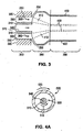
- FIG. 3 illustrates an example of a system and method of manufacturing an implantable medical device that uses radial expansion to induce circumferential molecular orientation.
- FIG. 3 depicts an axial cross-section of a portion of a forming apparatus 300.
- Forming apparatus 300 includes a first annular member 310, a second annular member 320, a first annular chamber 330, and a second annular chamber 340.
- Molten polymer in the form of an annular film 350 is conveyed through annular chamber 330 in the direction of arrows 360.
- a gas stream 370 at a selected pressure is conveyed through second annular chamber 340.
- Annular film 350 exits from forming apparatus 300 to an expansion region 380.
- Annular film 350 is radially expanded by gas 370 as it exits forming apparatus 300. As shown, annular film 350 is expanded to a diameter greater than the outer diameter of first annular member 310 and the inner diameter of the second annular member 320. Annular film 350 is then drawn into a cooling region 390 to form a polymer tube 400. For the purpose of comparison, FIG. 3 also depicts an annular film 410 formed without radial expansion. A polymer tube 420 formed from an annular film 410 is also depicted.
- Certain methods of manufacturing an implantable medical device with a forming apparatus may include inducing circumferential orientation by applying shear stress to a polymer.
- One method for manufacturing an implantable medical device may include introducing a polymer into a forming apparatus with a first annular member disposed within a second annular member.
- the first annular member may be a mandrel and the second annular member may be a die.
- the polymer may be conveyed through an annular chamber as an annular film between the annular members.
- the annular polymer film may be a polymer melt at a temperature above a T m of the polymer.
- the introduced polymer may be at a temperature above a T m of the polymer.
- the introduced polymer may be at a temperature below a T m of the polymer.
- the forming apparatus may be configured to melt the polymer.
- the polymer may be introduced in a mixture that includes the polymer and a solvent. As the mixture is conveyed through the apparatus as an annular film, at least some of the solvent may be vaporized and removed from the apparatus.
- the method may further include inducing circumferential flow in the annular film.
- a polymer tube may be formed from the annular film. It is advantageous for the temperature of the annular film to be greater than the melting temperature of the polymer.
- the annular film may be removed from the forming apparatus.
- the induced circumferential flow may induce circumferential orientation in the annular film, and hence in the resulting polymer tube.
- Some methods may then include fabricating an implantable medical device from the polymer tube.
- a mechanical property of the device may be more desirable than a mechanical property of an equivalent device formed from a polymer tube formed from an annular polymer film formed without circumferential flow.
- the dimensions of the polymer tube are equal to dimensions of the equivalent polymer tube formed from an annular polymer film formed without circumferential flow.
- fabrication of the equivalent device from the equivalent polymer tube is the same as the fabrication of the device from the polymer tube.
- the induced molecular orientation may result in more desirable mechanical properties such as greater circumferential strength and/or greater modulus or rigidity.
- the circumferential flow may be controlled to obtain a desired property of the implantable medical device.
- the annular film subjected to circumferential flow may be drawn to a desired diameter.
- the annular film may also be cooled during expansion and/or after drawing in the manner described above.
- Various methods of inducing circumferential orientation may be distinguished by the manner of inducing circumferential flow.
- Several methods may include inducing circumferential flow in the annular film by rotating the first annular member, the second annular member, or both annular members. It is expected that counter-rotation of both the first annular member and the second annular member may induce the greatest shear on the annular film, and hence, induce the greatest circumferential orientation.
- the degree of induced orientation may be controlled by parameters such as the rotation speed and relative rotation speed of the annular members.
- circumferential flow may be induced by a spiral channel on at least a portion of a surface of the rotating first annular member and/or the rotating second annular member.
- the spiral channel may tend to induce spiral circumferential molecular orientation in the annular polymer film.
- drawing the annular film may influence the induced circumferential molecular orientation.
- the annular polymer film is exposed to air at ambient temperature while it is being drawn.
- the cooling may cause dissipation in molecular orientation in the annular film. Therefore, the length of a drawing region may be directly proportional to a cooling rate of an annular film, and hence, the dissipation of molecular orientation.
- the rotational speed of annular member(s) may compensate for the dissipation in molecular orientation due to cooling.
- the rotational speed of annular members(s) is limited since the annular members may become unstable at sufficiently high rotation speeds.
- FIGs. 4A and 4B illustrate an example of a system and method of manufacturing an implantable medical device that uses circumferential flow to induce molecular orientation.
- FIG. 4A includes a radial cross-section of a forming apparatus 500 and FIG. 4B includes an axial cross-section of a portion of forming apparatus 500.
- Forming apparatus 500 includes a first annular member 510, a second annular member 520, a first annular chamber 530, and a second annular chamber 540.
- first annular member 510 and second annular member 520 are configured to rotate as depicted by arrows 515 and 525, respectively.
- FIG. 4A first annular member 510 and second annular member 520 are configured to rotate as depicted by arrows 515 and 525, respectively.
- annular film 550 shows that molten polymer in the form of an annular film 550 is conveyed through annular chamber 530 in the direction of arrows 560. Rotation of first annular member 510 and/or second annular member 520 induce circumferential flow in annular film 550. Annular film 550 is removed from forming apparatus 500 to a drawing region 580. As shown, annular film 550 is drawn to a desired diameter smaller than the diameter of second annular member 520. Annular film 550 is then drawn into a cooling region 590 to form a polymer tube 595.
- circumferential flow may be induced in the annular film with at least a portion of the annular film external to the apparatus.
- the annular film external to the apparatus may be positioned over or within a third annular member.
- the third annular member may be configured to rotate at least a portion of the annular film external apparatus.
- the annular film may exit the forming apparatus and be drawn over or within the third annular member being formed into the polymer tube.
- the rotating portion of the annular film may induce circumferential flow, and hence, circumferential molecular orientation in the annular film from at least a point of exit from the forming apparatus to the rotating third annular member.
- the degree of induced orientation may be controlled by the rotation speed of the third annular member.
- circumferential flow may be induced in at least a portion of the annular film external to the apparatus with at least a portion of the first annular member that is external to the apparatus. Rotation of the first annular member induces circumferential flow to at least a portion of the annular film external to the apparatus.
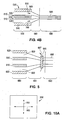
- FIG. 5 illustrates another example of a system and method with induced circumferential flow similar to the system and method depicted in FIGs. 4A and 4B.
- FIG. 5 also depicts an axial cross-section of a portion of a forming apparatus 600, similar to forming apparatus 500 in FIGs. 4A and 4B .
- the system in FIG. 5 further includes a third annular member 685.
- An annular film 650 exits from forming apparatus 600 to a drawing region 680.
- Annular film 650 is then positioned within third annular member 685.
- Third annular member 685 is configured to rotate, as shown by an arrow 687. Rotation of third annular member 685 induces circumferential flow on the portion of annular film 650 positioned on third annular member 685.
- Rotation of the portion of annular film 650 induces circumferential flow on the portion of annular film 650 at least in drawing region 680. As shown in FIG. 5 , annular film 650 is drawn further into a cooling region 690 to form a polymer tube 695. First annular member 610 and/or second annular member 620 may also be configured to rotate. Rotation of first annular member 610 and/or second annular member 620 may induce circumferential flow in annular film 650 within forming apparatus 600.
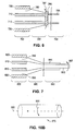
- FIG. 6 illustrates another example of a system and method with induced circumferential flow similar to the system and method depicted in FIG. 5 .
- FIG. 6 also depicts an axial cross-section of a portion of a forming apparatus 700, similar to forming apparatus 600 in FIG. 5 .
- the system in FIG. 6 includes a first annular member 710 that extends axially external to forming apparatus 700.
- An annular film 750 exits from forming apparatus 700 to a drawing region 780.
- Annular film 750 is then positioned within a third annular member 785.
- Third annular member 785 is configured to rotate, as shown by an arrow 787.
- Rotation of third annular member 785 induces circumferential flow on the portion of annular film 750 positioned on third annular member 785.
- Rotation of the portion of annular film 750 induces circumferential flow on the portion of annular film 750 at least in drawing region 780.
- annular film 750 is drawn further into a cooling region 790 to form polymer tube 795.
- First annular member 710 and/or second annular member 720 may also be configured to rotate. Rotation of first annular member 710 may induce circumferential flow in annular film 750 within forming apparatus 700 and within drawing region 780. Rotation of annular member 720 may induce circumferential flow in annular film 750 within forming apparatus 700.
- circumferential flow in the annular film may be induced by rotating the polymer tube.
- the polymer tube may be rotated by positioning the polymer tube over or within a third annular member that is configured to rotate the polymer tube.
- the annular film may be cooled to form the polymer tube.
- the rotating polymer tube may induce circumferential flow, and hence, circumferential orientation in the annular film from the polymer tube to at least the point of exit of the annular film from the apparatus.
- FIG. 7 illustrates another example of a system and method with induced circumferential flow similar to the system and method depicted in FIGs. 4-6 .
- FIG. 7 also depicts an axial cross-section of a portion of a forming apparatus 800, similar, for example, to forming apparatus 500 in FIG. 4B .
- the system in FIG. 7 includes a fourth annular member 805.
- An annular film 850 exits from forming apparatus 800 to a drawing region 880.
- annular film 850 is drawn into a cooling region 890 to form a polymer tube 895.
- Polymer tube 895 is positioned on fourth annular member 805.
- Fourth annular member 805 is configured to rotate, as shown by an arrow 807.
- fourth annular member 805 rotates polymer tube 895 which induces circumferential flow on the portion of annular film 850 at least in drawing region 880.
- First annular member 810 and/or second annular member 820 may also be configured to rotate to induce circumferential flow.
- some methods that include inducing circumferential orientation in a method of manufacturing implantable medical devices may include application of stress to a polymer at temperatures less than or equal to a T m of the polymer.
- circumferential molecular orientation in a polymer tube may be induced after fabrication of a tube.
- Certain methods of manufacturing an implantable medical device may include radially expanding a tube about a cylindrical axis of the tube from a first diameter to a second diameter. Some methods may include expanding a polymer tube plastically beyond the yield point or elastic limit of the polymer. The radial expansion of the polymer tube may induce circumferential molecular orientation, and hence, desired circumferential strength and modulus or rigidity in the polymer tube. As indicated above, a polymer expanded beyond its yield point tends to retain its expanded configuration, and hence, tends to retain the induced molecular orientation. An implantable medical device may then be fabricated from the expanded tube having a second diameter which is greater that the first diameter.
- the tube may be expanded radially by application of radial pressure. It may be desirable apply a pressure less than about an ultimate stress of the polymer to inhibit or prevent damage to the tube.
- radial pressure may be applied to the polymer tube by positioning the tube within an annular member and conveying a gas at a selected pressure into a proximal end of the polymer tube. A distal end of the polymer tube may be closed. The end may be open in subsequent manufacturing steps.
- the annular member may act to control the diameter of the expanded tube by limiting the expansion to the inside diameter of the annular member.
- the insider diameter of the annular member may correspond to a desired diameter of the tube.
- the pressure of the conveyed gas may be used to control the expansion of the tube to a desired diameter.
- Some methods may include applying heat to the tube to facilitate radial expansion of the tube.
- the tube may be heated prior to, contemporaneously with, and/or subsequent to applying radial pressure to the tube.
- the tube may be heated by conveying a gas at a temperature greater than an ambient temperature on and/or into the tube.
- Some methods may include cooling the expanded tube prior to fabrication of the medical device.
- the expanded tube may be cooled at a temperature below an ambient temperature.
- cooling the expanded polymer tube may include cooling the expanded polymer tube at a temperature at or near an ambient temperature.
- the device may include at least one mechanical property more desirable than an equivalent device fabricated from an equivalent polymer tube formed without radial expansion.
- the dimensions of the expanded polymer tube are equal to dimensions of the equivalent polymer tube formed without radial expansion.
- fabrication of the equivalent device from the equivalent polymer tube is the same as the fabrication of the device from the cooled polymer tube.
- Certain methods may include expanding the polymer tube at a temperature below a Tg of the polymer.
- Other methods may include expanding the polymer tube in a temperature range greater than or equal to a T g of the polymer and less than or equal to a T m of the polymer. Below T m , the polymer tube may retain its cylindrical shape even with applied pressure.
- the radial expansion may be controlled to obtain a desired degree of induced molecular orientation, and hence, a desired property of the implantable medical device.
- the applied pressure, temperature of the polymer tube, and the cooling rate of the polymer tube may be controlled to obtain desired properties, such as circumferential strength and/or modulus or rigidity, of the expanded polymer tube.
- FIGs. 8A and 8B illustrate a method of expanding a polymer tube for use in manufacturing an implantable medical device.
- FIG. 8A depicts an axial cross-section of a polymer tube 900 with an outside diameter 905 positioned within an annular member 910.
- Annular member 910 may act as a mold that limits the expansion of polymer tube 900 to a diameter 915, the inside diameter of annular member 910.
- Polymer tube 900 may be closed at a distal end 920.
- Distal end 920 may be open in subsequent manufacturing steps.
- a gas such as air or an inert gas, may be conveyed, as indicated by an arrow 925, into an open proximal end 930 of polymer tube 900.
- Polymer tube 900 may be heated by heating the gas to a temperature above ambient temperature prior to conveying the gas into polymer tube 900. Alternatively, heat may be applied to the exterior of annular member 910. The conveyed gas combined with the applied heat may act to radially expand polymer tube 900, as indicated by an arrow 935.
- FIG. 8B depicts polymer tube 900 in an expanded state with an outside diameter 940 within annular member 910.
- implantable medical devices may be fabricated from tubes that are formed from planar polymer films or sheets.
- a "film” or “sheet” refers to something that is thin in comparison to its length and breadth.
- a tube may be formed from a film by rolling a film into a cylindrical shape. The sheet may then be bonded with a suitable adhesive. The film may be bonded at opposing edges of the film that are parallel or substantially parallel to a cylindrical axis. The film may be cut so that the formed tube is a desired diameter.
- Polymer films or sheets may be made by several different processes.
- a blown film or sheet can be made by expansion and stretching of a preform or parison.
- the preform or parison refers to a hollow molten tube extruded from the die head of a blow molding machine expanded within the mold. In the blow molding process, air is blown into the parison and it forms a bubble. The bubble is then drawn through rollers, which stretch the film or sheet to the appropriate thickness.
- a polymer film may also be made by extrusion through a slit die, such as compression molding.
- cast film may be made from a cast-film or chill-roll extrusion process.
- a polymer film with a desired degree of biaxial molecular orientation may be fabricated from blown, cast, or extruded film using biaxial stretching.
- Certain methods of manufacturing an implantable medical device may include stretching a film along a first axis of stretching.
- the method may further include stretching the film along a second axis of stretching.
- the film may be stretched by application of a tensile force or drawing tension. The stretching of the film may induce molecular orientation in the polymer film, and hence high strength and modulus or rigidity, along the first axis of stretching and the second axis of stretching.
- Certain methods may include fabricating an implantable medical device from the stretched film.
- fabricating an implantable medical device from the stretched film may include forming a tube from the stretched film.
- Some methods of fabricating an implantable medical device from the stretched film may include forming a pattern having at least one strut on at least a portion of the tube.
- a pattern may be formed on the stretched film prior to forming a tube from the stretched sheet.
- a mechanical property of the device may be more desirable than a mechanical property of an equivalent device fabricated from an unstretched film.
- the dimensions of the device are equal to dimensions of the equivalent device formed from an unstretched polymer film.
- the fabrication of the equivalent device is the same as the fabrication of the device.
- the stretching may be controlled to obtain a desired degree of induced molecular orientation, and hence, desired properties of the implantable medical device.
- the stretching may be controlled by controlling various process parameters such as tensile force used for stretching, the relative values of the tensile force applied along the axes, and the temperature of the film during stretching.
- a polymer film may be stretched using a tenter.
- stretching is performed inside of a box that may be temperature-controlled. Inside of the box, a film is grasped on either side by tenterhooks that exert a tensile force or drawing tension along at least one axis.
- the degree of stretching along the axes may be substantially equal, or alternatively, unbalanced. Therefore, the mechanical properties of a polymer tube formed from a stretched film may be controlled by the degree of stretching along each axis and also by the relative amount stretching along the axes.
- a tube may be formed to have a desired relative orientation of a cylindrical axis of the tube with at least one stretching axis.
- a cylindrical axis of a tube formed from the stretched sheet may be parallel, perpendicular, or at an angle between parallel and perpendicular to the first axis of stretching and/or the second axis of stretching.
- FIG. 9 depicts an x-y coordinate plane 942 for illustrating the relationship between an axis of stretching 944 and a cylindrical axis 946 of a tube formed from a stretched sheet.
- An angle 948 is the relative orientation between axis of stretching 944 and cylindrical axis 946.
- FIG. 10A illustrates a polymer film 950 that has been stretched along two axes indicated by arrows 955 and 960 to have biaxial molecular orientation.
- FIG. 10B depicts a polymer tube 975 formed from polymer film 950. Polymer tube 975 is formed so that the axes depicted by arrows 955 and 960 in FIG. 10A are along the radial direction and cylindrical axis of polymer tube 975, respectively.
- the film may be stretched plastically beyond the yield point or elastic limit of the polymer along the first axis of stretching and/or the second axis of stretching.
- it may be desirable to stretch with a force that applies a stress that is less than an ultimate stress of the polymer to inhibit or prevent damage to the film.
- the polymer tube may be stretched elastically. After stretching, an elastically stretched film may be cooled relatively quickly to inhibit contraction and dissipation of induced molecular orientation.
- the stretched film may be cooled at a temperature substantially below an ambient temperature.
- a polymer film may be stretched at a temperature greater than or equal to a T g and less than or equal to a T m of the polymer. Below a T m , a planar polymer film may retain its shape even with applied tensile force or tension. In another method, the film may be stretched at a temperature less than or equal to a Tg of the polymer. Additionally, the temperature of the film may be controlled to obtain desired properties, such as circumferential strength and/or modulus or rigidity, of a polymer tube formed from the stretched film.
Description
- This invention relates to methods of fabricating implantable medical devices such as stents, according to claim 1.
- This invention relates to radially expandable endoprostheses which are adapted to be implanted in a bodily lumen. An "endoprosthesis" corresponds to an artificial implantable medical device that is placed inside the body. A "lumen" refers to a cavity of tubular organ such as a blood vessel. A stent is an example of these endoprostheses. Stents are generally cylindrically shaped devices which function to hold open and sometimes expand a segment of a blood vessel or other anatomical lumen such as urinary tracts and bile ducts. Stents are often used in the treatment of atherosclerotic stenosis in blood vessels. "Stenosis" refers to a narrowing or constriction of the diameter of a bodily passage or orifice. In such treatments, stents reinforce body vessels and prevent restenosis following angioplasty in the vascular system. "Restenosis" refers to the reoccurrence of stenosis in a blood vessel or heart valve after it has been treated (as by balloon angioplasty or valvuloplasty) with apparent success.
- Stents have been made of many materials including metals and polymers. Polymer materials include both nonbioerodable and bioerodable plastic materials. The cylindrical structure of stents is typically composed of a scaffolding that includes a pattern or network of interconnecting structural elements or struts. The scaffolding can be formed from wires, tubes, or planar films of material rolled into a cylindrical shape. In addition, a medicated stent may be fabricated by coating the surface of either a metallic or polymeric scaffolding with a polymeric carrier. The polymeric carrier can include an active agent or drug. Furthermore, the pattern that makes up the stent allows the stent to be radially expandable and longitudinally flexible. Longitudinal flexibility facilitates delivery of the stent and rigidity is needed to hold open a body lumen. The pattern should be designed to maintain the longitudinal flexibility and rigidity required of the stent. A stent should also have adequate strength in the circumferential direction.
- A number of techniques have been suggested for the fabrication of stents from tubes and planar films or sheets. One such technique involves laser cutting or etching a pattern onto a material. Laser cutting may be performed on a planar film of a material which is then rolled into a tube. Alternatively, a desired pattern may be etched directly onto a tube. Other techniques involve cutting a desired pattern into a sheet or a tube via chemical etching or electrical discharge machining. Laser cutting of stents has been described in a number of publications including
U.S. Pat. No. 5,780,807 to Saunders ,U.S. Pat. No. 5,922,005 to Richter andU.S. Pat. No. 5,906,759 to Richter . - A treatment involving a stent involves both delivery and deployment of the stent. "Delivery" refers to introducing and transporting the stent through a bodily lumen to a region requiring treatment. "Deployment" corresponds to the expanding of the stent within the lumen at the treatment region. Delivery and deployment of a stent are accomplished by positioning the stent about one end of a catheter, inserting the end of the catheter through the skin into a bodily lumen, advancing the catheter in the bodily lumen to a desired treatment location, expanding the stent at the treatment location, and removing the catheter from the lumen. In the case of a balloon expandable stent, the stent is mounted about a balloon disposed on the catheter. Mounting the stent typically involves compressing or crimping the stent onto the balloon. The stent is then expanded by inflating the balloon. The balloon may then be deflated and the catheter withdrawn. In the case of a self-expanding stent, the stent may be secured to the catheter via a retractable sheath or a sock. When the stent is in a desired bodily location, the sheath may be withdrawn allowing the stent to self-expand.
- It is desirable for a stent to have certain mechanical properties to facilitate delivery and deployment of the stent. For example, longitudinal flexibility is important for successful delivery of the stent. In addition, circumferential strength and rigidity and are vital characteristics in deployment and for holding open a body lumen. As indicated above, the pattern of the stent may be designed to provide longitudinal flexibility and rigidity.
- However, the characteristics of the material of which a stent is composed also affects the mechanical properties of the stent. An advantage of stents fabricated from polymers is that they tend to possess greater flexibility than metal stents. Other potential shortcomings of metal stents include adverse reactions from the body, nonbioerodability, and non-optimal drug-delivery. However, a potential shortcoming of polymer stents compared to metal stents, is that polymer stents typically have less circumferential strength and rigidity. Inadequete circumferential strength potentially contributes to relatively high recoil of polymer stents after implantation into vessels. Furthermore, another potential problem with polymer stents is that struts can crack during crimping, especially for brittle polymers.
-
US 2003/0187158 relates to polyolefins and in particular to polyolefins comprising a C3-C20 monomer and having a molecular weight of at least 700 kg/mol preferably 1000 kg/mol. There is also described a hafnium based metallocene catalyst and a process for making such polyolefins. Articles made according to the disclosure may take the form of articles which are intended to be used in contact with or in proximity to the body of a living being. Such articles may be disposable or intended for multiple or prolonged use. Such articles include but are not limited to catheters, tubing, drainage systems, syringes, grafts, prosthetics, body implants, instrumentation, support means, toothbrushes, bed covers, stents, gaskets, pump diaphragms, baby bottle nipples, pacifiers, and the like. - By contrast, in
US 4,698,196 there is described an apparatus for preparing seamless, creaseless, pliable, thin-walled tubes comprising means to extrude a moving continuous tube of polymeric film material from a die, means to radially stretch the continuous tube as it emerges from the die, means to longitudinally stretch the tube, and means to sever the tube while the tube is in motion to form tube segments while maintaining the tube substantially free of creases. This apparatus may be employed in a process to prepare seamless, creaseless, pliable, thin-walled tubes. - In
US 2003/0226833 there is described a method whereby a desired pattern may be cut into a stent preform by impinging a laser beam onto the stent preform. The laser beam is formed using a laser system comprising a resonator cavity for resonating laser radiation, a gain medium contained in the resonator cavity, a pump for periodically pumping the gain medium and an electro-optical modulator in communication with the resonator cavity. The laser system produces a radiation pulse for each pump period. Each radiation pulse is conditioned by suppressing at least a portion of the pulse. The pulse may also be modulated with an electro-optical modulator to produce a pulse train of ordered pulses of radiation. Each pulse train is output from the optical cavity as an output laser beam which is directed at the stent preform to cut a desired pattern in the stent preform. - Nonetheless, methods of manufacturing polymer stents that improve circumferential strength and rigidity are desirable. The embodiments of the present invention address the issue of improving circumferential strength and rigidity in polymer stents.
- The present invention is directed to methods for fabricating an implantable medical device, such as a stent, from a tube, with desirable mechanical properties, such as improved circumferential strength and rigidity. Improved circumferential strength and rigidity may be obtained by inducing circumferential molecular orientation in materials for use in manufacturing an implantable medical device. Various embodiments of the present invention include methods for inducing circumferential molecular orientation in a material.
- According to the present invention there is provided a method of manufacturing an implantable medical device, comprising: introducing a polymer into a forming apparatus comprising a first annular member disposed within a second annular member, wherein the polymer is conveyed through an annular chamber as an annular film between the annular members; inducing circumferential flow in the annular film; forming a tube from the annular film; and fabricating an implantable medical device from the tube, wherein the circumferential flow is induced in the annular film by rotating the tube, and the tube is rotated by positioning the tube over or within a third annular member that is configured to rotate the tube.
- Other methods of fabricating an implantable medical device are also described.
-
-
FIG. 1 depicts a tube. -
FIG. 2 depicts a three-dimensional rendering of an implantable medical device with a pattern. -
FIG. 3 depicts a system and method of manufacturing an implantable medical device. -
FIG. 4A depicts a radial cross-section of a forming apparatus. -
FIGs. 4B-7 depict an axial cross-section of a forming apparatus. -
FIGs. 8A and 8B depict a method of expanding a tube. -
FIG. 9 depicts an x-y coordinate plane. -
FIG. 10A depicts a film. -
FIG. 10B depicts a tube. - For the purposes of the present invention, the following terms and definitions apply:
- "Stress" refers to force per unit area, as in the force acting through a small area within a plane. Stress can be divided into components, normal and parallel to the plane, called normal stress and shear stress, respectively. True stress denotes the stress where force and area are measured at the same time. Conventional stress, as applied to tension and compression tests, is force divided by the original gauge length.
- The term "elastic deformation" refers to deformation of an object in which the applied stress is small enough so that the object retains its original dimensions or essentially its original dimensions once the stress is released.
- "Elastic limit" refers to the maximum stress that a material will withstand without permanent deformation.
- The term "plastic deformation" refers to permanent deformation that occurs in a material under stress after elastic limits have been exceeded.
- "Strength" refers to the maximum stress along an axis in testing which a material will withstand prior to fracture. The ultimate strength is calculated from the maximum load applied during the test divided by the original cross-sectional area.
- "Modulus" may be defined as the ratio of the stress or force per unit area applied to a material divided by the amount of strain resulting from the applied force.
- "Strain" refers to the amount of elongation or compression that occurs in a material at a given stress or load.
- "Elongation" may be defined as the increase in length which occurs when subjected to stress. It is typically expressed as a percentage of the original length.
- "Solvent" is defined as a substance capable of dissolving or dispersing one or more other substances or capable of at least partially dissolving or dispersing the substance(s) to form a uniformly dispersed mixture at the molecular- or ionic-size level. The solvent should be capable of dissolving at least 0.1 mg of the polymer in 1 ml of the solvent, and more narrowly 0.5 mg in 1 ml at ambient temperature and ambient pressure. A second fluid can act as a non-solvent for the impurity. "Non-solvent" is defined as a substance incapable of dissolving the other substance. The non-solvent should be capable of dissolving only less than 0.1 mg of the polymer in 1 ml of the non-solvent at ambient temperature and ambient pressure, and more narrowly only less than 0.05 mg in 1 ml at ambient temperature and ambient pressure.
- Implantable medical device is intended to include self-expandable stents, balloon-expandable stents, stent-grafts, and grafts. The structural pattern of the device can be of virtually any design. The device can also be made partially or completely from a biodegradable, bioabsorbable, or biostable polymer. The polymer may be purified to remove undesirable materials.
- Polymers can be biostable, bioabsorbable, biodegradable or bioerodable. Biostable refers to polymers that are not biodegradable. The terms biodegradable, bioabsorbable, and bioerodable are used interchangeably and refer to polymers that are capable of being completely degraded and/or eroded when exposed to bodily fluids such as blood and can be gradually resorbed, absorbed and/or eliminated by the body. The processes of breaking down and eventual absorption and elimination of the polymer can be caused by, for example, hydrolysis, metabolic processes, bulk or surface erosion, and the like. If the material is used in coating applications, it is understood that after the process of degradation, erosion, absorption, and/or resorption has been completed, no polymer will remain on the device. In some examples, very negligible traces or residue may be left behind. For stents made from a biodegradable polymer, the stent is intended to remain in the body for a duration of time until its intended function of, for example, maintaining vascular patency and/or drug delivery is accomplished.
- Representative examples of polymers that may be used to fabricate an implantable medical device using the methods disclosed herein include poly(N-acetylglucosamine) (Chitin), Chitoson, poly(hydroxyvalerate), poly(lactide-co-glycolide), poly(hydroxybutyrate), poly(hydroxybutyrate-co-valerate), polyorthoester, polyanhydride, poly(glycolic acid), poly(glycolide), poly(L-lactic acid), poly(L-lactide), poly(D,L-lactic acid), poly(D,L-lactide), poly(caprolactone), poly(trimethylene carbonate), polyethylene amide, polyethylene acrylate, poly(glycolic acid-co-trimethylene carbonate), co-poly(ether-esters) (e.g. PEO/PLA), polyphosphazenes, biomolecules (such as fibrin, fibrinogen, cellulose, starch, collagen and hyaluronic acid), polyurethanes, silicones, polyesters, polyolefins, polyisobutylene and ethylene-alphaolefin copolymers, acrylic polymers and copolymers other than polyacrylates, vinyl halide polymers and copolymers (such as polyvinyl chloride), polyvinyl ethers (such as polyvinyl methyl ether), polyvinylidene halides (such as polyvinylidene chloride), polyacrylonitrile, polyvinyl ketones, polyvinyl aromatics (such as polystyrene), polyvinyl esters (such as polyvinyl acetate), acrylonitrile-styrene copolymers, ABS resins, polyamides (such as Nylon 66 and polycaprolactam), polycarbonates, polyoxymethylenes, polyimides, polyethers, polyurethanes, rayon, rayon-triacetate, cellulose, cellulose acetate, cellulose butyrate, cellulose acetate butyrate, cellophane, cellulose nitrate, cellulose propionate, cellulose ethers, and carboxymethyl cellulose. Additional representative examples of polymers that may be especially well suited for use in fabricating an implantable medical device according to the methods disclosed herein include ethylene vinyl alcohol copolymer (commonly known by the generic name EVOH or by the trade name EVAL), poly(butyl methacrylate), poly(vinylidene fluoride-co-hexafluororpropene) (e.g., SOLEF 21508, available from Solvay Solexis PVDF, Thorofare, NJ), polyvinylidene fluoride (otherwise known as KYNAR, available from ATOFINA Chemicals, Philadelphia, PA), ethylene-vinyl acetate copolymers, and polyethylene glycol.
- It is well known by those skilled in the art of polymer technology that the mechanical properties of a polymer may be modified by processes that alter the molecular structure of the polymer. Polymers in the solid state may be completely amorphous, partially crystalline, or almost completely crystalline. Crystalline regions in a polymer are characterized by alignment of polymer chains along the longitudinal or covalent axis of the polymer chains. An oriented crystalline structure tends to have high strength and a high modulus (low elongation with applied stress) along an axis of alignment of polymer chains. A high modulus material tends to have a high degree of rigidity. Therefore, a region of a polymeric material with a high degree of oriented crystalline structure tends to have high strength and rigidity along an axis of polymer chain alignment. Therefore, it may be desirable to incorporate processes that induce molecular orientation of polymer chains along a preferred axis or direction into manufacturing methods of implantable medical devices.
- Furthermore, molecular orientation in a polymer may be induced, and hence mechanical properties modified, by applying stress to the polymer. The degree of molecular orientation induced with applied stress may depend upon the temperature of the polymer. For example, below the glass transition temperature, Tg, of a polymer, polymer segments may not have sufficient energy to move past one another. In general, molecular orientation may not be induced without sufficient segmental mobility.
- The "glass transition temperature," Tg, is the temperature at which the amorphous domains of a polymer change from a brittle vitreous state to a solid deformable state at atmospheric pressure. In other words, the Tg corresponds to the temperature where the onset of segmental motion in the chains of the polymer occurs. When an amorphous or semicrystalline polymer is exposed to an increasing temperature, the coefficient of expansion and the heat capacity of the polymer both increase as the temperature is raised, indicating increased molecular motion. As the temperature is raised the actual molecular volume in the sample remains constant, and so a higher coefficient of expansion points to an increase in free volume associated with the system and therefore increased freedom for the molecules to move. The increasing heat capacity corresponds to an increase in heat dissipation through movement. Tg of a given polymer can be dependent on the heating rate and can be influenced by the thermal history of the polymer. Furthermore, the chemical structure of the polymer heavily influences the glass transition by affecting mobility. Generally, flexible main-chain components lower the Tg; bulky side-groups raise the Tg; increasing the length of flexible side-groups lowers the Tg; and increasing main-chain polarity increases the Tg. Additionally, the presence of crosslinking polymeric components can increase the observed Tg for a given polymer.
- Above Tg, molecular orientation may be readily induced with applied stress since rotation of polymer chains, and hence segmental mobility, is possible. Between Tg and the melting temperature of the polymer, Tm, rotational barriers exist, however, the barriers are not great enough to substantially prevent segmental mobility. As the temperature of a polymer is increased above Tg, the energy barriers to rotation decrease and segmental mobility of polymer chains tend to increase. As a result, as the temperature increases, molecular orientation is more easily induced with applied stress.
- Moreover, application of stress to a polymer between Tg and the melting temperature of the polymer, Tm, may induce molecular orientation of the polymer, and hence, modify its mechanical properties. However, rearrangement of polymer chains may take place when a polymer is stressed in an elastic region and in a plastic region of the polymer material. A polymer stressed beyond its elastic limit to a plastic region generally retains its stressed configuration and corresponding induced molecular orientation when stress is removed. The polymer chains may become oriented in the direction of the applied stress which results in an oriented crystalline structure. The stressed polymer material may have a higher tensile strength in the direction of the applied stress.
- Furthermore, as indicated above, a plastically deformed material tends to retain its deformed configuration once the deforming stress is removed. Stress applied to the material subsequent to the initial deforming stress tends not to cause further deformation of the material unless the applied stress is greater than the initial stress level that caused the deformation. Therefore, the behavior of a plastically deformed material may be more predictable within a range of stress. The stress range may be less than the initial stress applied that caused the plastic deformation.
- Additionally, application of heat with stress may facilitate deformation of a polymer under stress, and hence, modification of the mechanical properties of the polymer. A polymer deformed elastically with stress facilitated with applied heat may retain induced molecular orientation by cooling the polymer before relaxing to an unstrained state.
- Furthermore, above Tm, a polymer exists as a polymer melt or in a molten state. In a polymer melt, there is a very small barrier to bond rotation, and hence, segmental mobility of polymer chains is very high. As suggested above, the higher the temperature, the greater the segmental mobility, or generally, the more intense the molecular motion. Therefore, applying stress to a polymer melt may also induce molecular orientation. Stress may be applied to a polymer melt in the form of a film as an isotropic stress or pressure which results in expansion of the film, as in a bubble. The expansion may result in circumferential molecular orientation in a direction of induced strain along the surface of the expanded film. Alternatively, a shear stress may be applied which induces flow in the polymer melt. The molecular orientation may tend to be in the direction or along an axis of applied shear stress or flow. However, due to intense molecular motion, the induced molecular orientation is not stable. Once the shear stress is removed or the flow slows or stops, molecular motion may tend to dissipate the molecular orientation. The highest temperature at which molecular orientation is stable is less than or equal to the Tm of the polymer. Therefore, it may be necessary to reduce the temperature of a polymer melt below Tm to inhibit or prevent dissipation of molecular orientation.
- Various methods for manufacturing an implantable medical device with desirable mechanical properties are described herein. Some methods of manufacturing an implantable medical device include fabricating the implantable medical device from a polymer conduit or tube. The tube may be cylindrical or substantially cylindrical in shape. For example,
FIG. 1 depicts atube 100.Tube 100 is a cylinder with anoutside diameter 110 and aninside diameter 120.FIG. 1 also depicts asurface 130 and acylindrical axis 140 oftube 100. When referred to below, unless otherwise specified, the "diameter" of the tube refers to the outside diameter of tube. In some methods, the diameter of the tube prior to fabrication of the implantable medical device may be between about 0.5 mm and about 3.0 mm. In other methods, the diameter of the tube prior to fabrication may be between about 1 mm and 2 mm. An example of a tube prior to fabrication may include one with a diameter of 2.13 mm (0.084 in). - An implantable medical device may be fabricated from a polymer tube. Fabrication may include forming a pattern that includes at least one interconnecting element or strut on the tube. Forming a pattern on the tube may include laser cutting a pattern on the tube. Representative examples of lasers that may be used include an excimer, carbon dioxide, and YAG. In other methods, chemical etching may be used to form a pattern on the tube. It is desirable to use a laser cutting technique which minimizes a size of a heat affected zone. A heat affected zone refers to a region of a target material affected by the heat of the laser. Heat from the laser may tend to melt at least a portion of polymer in the heat affected zone. The molecular orientation induced by applied stress may then be dissipated in the melted portion. The corresponding favorable change in mechanical properties may also be reduced or substantially eliminated.
FIG. 2 depicts a three-dimensional view of an implantablemedical device 150 which may be formed fromtube 100 inFIG. 1 . -
FIG. 2 depicts an implantablemedical device 150 that includes a pattern ofstruts 60. The final etched out pattern should not be limited to what has been illustrated as other stent patterns are easily applicable. - As discussed above, it is desirable for a polymer tube for use in manufacturing an implantable medical device to have adequate strength in the longitudinal direction, as shown by an
arrow 135 inFIG. 1 . Strength in the circumferential direction, as shown by anarrow 145 inFIG. 1 , is also very important. A tube with biaxial molecular orientation, or equivalently, a tube with a desired degree of molecular orientation in both the longitudinal and the circumferential directions may possess the desirable mechanical properties. Implantable medical devices, such as stents, fabricated from tubes with biaxial orientation may possess mechanical properties similar to or better than metal stents with an acceptable wall thickness and strut width. Several methods of manufacturing implantable medical devices with biaxial orientation, and hence, with desired mechanical properties are described herein. - Polymer tubes may be formed by means of various types of forming methods, including, but not limited to extrusion or injection molding. Alternatively, a polymer tube may be formed from sheets or films that are rolled and bonded. In extrusion, a polymer melt is conveyed through an extruder which is then formed into a tube. Extrusion tends to impart large forces on the molecules in the longitudinal direction of the tube due to shear forces on the polymer melt. The shear forces arise from forcing the polymer melt through a die and pulling and forming the polymer melt into the small dimensions of a tube. As a result, polymer tubes formed by conventional extrusion methods tend to possess a significant degree of longitudinal orientation. However, conventionally extruded tubes tend to possess no or substantially no orientation in the circumferential direction.
- Several methods of manufacturing implantable medical devices with biaxial orientation may include the use of a forming apparatus, such as an extruder. Representative examples of forming apparatuses may include single screw extruders, intermeshing co-rotating and counterrotating twin-screw extruders and other multiple screw masticating extruders.
- Certain methods of manufacturing an implantable medical device with a forming apparatus may include radial expansion of an annular polymer film. One method may include introducing a polymer into a forming apparatus that includes a first annular member disposed within a second annular member. The first annular member may be a mandrel and the second annular member may be a die. The polymer may be conveyed through an annular chamber as an annular film between the annular members. In some methods, the annular polymer film may be a polymer melt at a temperature above Tm of the polymer.
- In one method, the introduced polymer may be at a temperature above a Tm of the polymer. Alternatively, the introduced polymer may be at a temperature below a Tm of the polymer. The forming apparatus may be configured to melt the polymer. In another method, the polymer may be introduced in a mixture that includes the polymer and a solvent. As the mixture is conveyed through the apparatus as an annular film, at least some of the solvent may be vaporized and removed from the apparatus. Representative examples of solvents may include chloroform, acetone, chlorobenzene, ethyl acetate, 1,4-dioxane, ethylene dichloride, 2-ethyhexanol, and combinations thereof.
- Some methods may further include radially expanding the annular film. In one method, the annular film may be expanded after exiting from the apparatus. In one method, the annular film may be expanded with a gas at a selected pressure. The gas may be conveyed through a second annular chamber within the first annular member. A tube may then be formed from the expanded annular film. The radial expansion may induce circumferential orientation in the annular film, and hence in the resulting tube.
- The method may further include fabricating an implantable medical device from the tube. The fabricated device may have at least one mechanical property more desirable than an equivalent device fabricated from an equivalent polymer tube formed from an annular film without radial expansion. The dimensions of the polymer tube are equal to dimensions of the equivalent polymer tube formed from an annular film without radial expansion. Additionally, the fabrication of the equivalent device from the equivalent polymer tube is the same as the fabrication of the device from the polymer tube.
- The induced molecular orientation may result in more desirable mechanical properties such as greater circumferential strength and/or greater rigidity. In general, the radial expansion may be controlled to obtain a desired property of the implantable medical device. For example, the pressure of the gas and the temperature of the annular film influence the radial expansion.
- In one method, the expanded annular film may be drawn to a desired diameter subsequent to radial expansion. In some methods, the annular film may be drawn by a puller. The puller may include a conveyor assembly that supports and sizes the annular film. The expanded annular film may be cooled during expansion and/or after drawing. For example, the annular film may be conveyed through a water bath at a selected temperature. Alternatively, the annular film may be cooled by air or some other gas at a selected temperature.
- As indicated above, it is desirable to cool the polymer melt to inhibit dissipation of the induced circumferential molecular orientation. In one method, the cooling rate may be used to control the degree of induced molecular orientation in the polymer tube. The annular film may be cooled at or near an ambient temperature, e.g. 25 °C. Alternatively, the annular film may be cooled at a temperature below ambient temperature.
- In certain methods, the gas used to expand the annular film may be conveyed through a second annular chamber within the first annular member. The gas may be air or some other conveniently available gas. The gas may be an inert gas such as argon, nitrogen, etc. The pressure of the gas may be selected to expand the annular film to a desired inside diameter and outside diameter. For example, the flow of the gas may be configured to expand the annular film to an outer diameter larger than the second annular member and an inner diameter larger than the first annular member. In addition, the pressure of the gas may be controlled to obtain a desired property or a desired improvement of a property of the implantable medical device. For example, the greater the radial expansion, the more circumferential molecular orientation may be induced in the annular film. Furthermore, the drawing speed may also be controlled to obtain a desired degree of induced circumferential orientation. As the drawing speed is increased, the degree of induced circumferential orientation decreases.
- It is desirable for the temperature of the annular film during expansion to be greater than the melting temperature of the polymer. As discussed above, the higher the temperature, the greater the segmental mobility of polymer chains. Therefore, temperature may be used to control the degree of molecular orientation in the annular film, and hence, to obtain desired mechanical properties of the implantable medical device.
-
FIG. 3 illustrates an example of a system and method of manufacturing an implantable medical device that uses radial expansion to induce circumferential molecular orientation.FIG. 3 depicts an axial cross-section of a portion of a formingapparatus 300. Formingapparatus 300 includes a firstannular member 310, a secondannular member 320, a firstannular chamber 330, and a secondannular chamber 340. Molten polymer in the form of anannular film 350 is conveyed throughannular chamber 330 in the direction ofarrows 360. Agas stream 370 at a selected pressure is conveyed through secondannular chamber 340.Annular film 350 exits from formingapparatus 300 to anexpansion region 380.Annular film 350 is radially expanded bygas 370 as it exits formingapparatus 300. As shown,annular film 350 is expanded to a diameter greater than the outer diameter of firstannular member 310 and the inner diameter of the secondannular member 320.Annular film 350 is then drawn into acooling region 390 to form apolymer tube 400. For the purpose of comparison,FIG. 3 also depicts anannular film 410 formed without radial expansion. Apolymer tube 420 formed from anannular film 410 is also depicted. - Certain methods of manufacturing an implantable medical device with a forming apparatus may include inducing circumferential orientation by applying shear stress to a polymer. One method for manufacturing an implantable medical device may include introducing a polymer into a forming apparatus with a first annular member disposed within a second annular member. The first annular member may be a mandrel and the second annular member may be a die. The polymer may be conveyed through an annular chamber as an annular film between the annular members. In some methods, the annular polymer film may be a polymer melt at a temperature above a Tm of the polymer.
- In one method, the introduced polymer may be at a temperature above a Tm of the polymer. Alternatively, the introduced polymer may be at a temperature below a Tm of the polymer. The forming apparatus may be configured to melt the polymer. In another method, the polymer may be introduced in a mixture that includes the polymer and a solvent. As the mixture is conveyed through the apparatus as an annular film, at least some of the solvent may be vaporized and removed from the apparatus.
- In some examples, the method may further include inducing circumferential flow in the annular film. A polymer tube may be formed from the annular film. It is advantageous for the temperature of the annular film to be greater than the melting temperature of the polymer. The annular film may be removed from the forming apparatus.
- In one method, the induced circumferential flow may induce circumferential orientation in the annular film, and hence in the resulting polymer tube. Some methods may then include fabricating an implantable medical device from the polymer tube.
- In certain cases, a mechanical property of the device may be more desirable than a mechanical property of an equivalent device formed from a polymer tube formed from an annular polymer film formed without circumferential flow. The dimensions of the polymer tube are equal to dimensions of the equivalent polymer tube formed from an annular polymer film formed without circumferential flow. Additionally, fabrication of the equivalent device from the equivalent polymer tube is the same as the fabrication of the device from the polymer tube. The induced molecular orientation may result in more desirable mechanical properties such as greater circumferential strength and/or greater modulus or rigidity. In general, the circumferential flow may be controlled to obtain a desired property of the implantable medical device.
- In one method, the annular film subjected to circumferential flow may be drawn to a desired diameter. The annular film may also be cooled during expansion and/or after drawing in the manner described above.
- Various methods of inducing circumferential orientation may be distinguished by the manner of inducing circumferential flow. Several methods may include inducing circumferential flow in the annular film by rotating the first annular member, the second annular member, or both annular members. It is expected that counter-rotation of both the first annular member and the second annular member may induce the greatest shear on the annular film, and hence, induce the greatest circumferential orientation. In some methods, the degree of induced orientation may be controlled by parameters such as the rotation speed and relative rotation speed of the annular members.
- In certain methods, circumferential flow may be induced by a spiral channel on at least a portion of a surface of the rotating first annular member and/or the rotating second annular member. The spiral channel may tend to induce spiral circumferential molecular orientation in the annular polymer film.
- Moreover, drawing the annular film may influence the induced circumferential molecular orientation. Typically, the annular polymer film is exposed to air at ambient temperature while it is being drawn. As a result, the annular film tends to cool as it is drawn. The cooling may cause dissipation in molecular orientation in the annular film. Therefore, the length of a drawing region may be directly proportional to a cooling rate of an annular film, and hence, the dissipation of molecular orientation. The rotational speed of annular member(s) may compensate for the dissipation in molecular orientation due to cooling. However, the rotational speed of annular members(s) is limited since the annular members may become unstable at sufficiently high rotation speeds.
-
FIGs. 4A and4B illustrate an example of a system and method of manufacturing an implantable medical device that uses circumferential flow to induce molecular orientation.FIG. 4A includes a radial cross-section of a formingapparatus 500 andFIG. 4B includes an axial cross-section of a portion of formingapparatus 500. Formingapparatus 500 includes a firstannular member 510, a secondannular member 520, a firstannular chamber 530, and a secondannular chamber 540. As depicted byFIG. 4A , firstannular member 510 and secondannular member 520 are configured to rotate as depicted byarrows FIG. 4B shows that molten polymer in the form of anannular film 550 is conveyed throughannular chamber 530 in the direction ofarrows 560. Rotation of firstannular member 510 and/or secondannular member 520 induce circumferential flow inannular film 550.Annular film 550 is removed from formingapparatus 500 to adrawing region 580. As shown,annular film 550 is drawn to a desired diameter smaller than the diameter of secondannular member 520.Annular film 550 is then drawn into acooling region 590 to form apolymer tube 595. - In another method, circumferential flow may be induced in the annular film with at least a portion of the annular film external to the apparatus. The annular film external to the apparatus may be positioned over or within a third annular member. The third annular member may be configured to rotate at least a portion of the annular film external apparatus. In one method, the annular film may exit the forming apparatus and be drawn over or within the third annular member being formed into the polymer tube. The rotating portion of the annular film may induce circumferential flow, and hence, circumferential molecular orientation in the annular film from at least a point of exit from the forming apparatus to the rotating third annular member. The degree of induced orientation may be controlled by the rotation speed of the third annular member.
- In certain methods, circumferential flow may be induced in at least a portion of the annular film external to the apparatus with at least a portion of the first annular member that is external to the apparatus. Rotation of the first annular member induces circumferential flow to at least a portion of the annular film external to the apparatus.
-
FIG. 5 illustrates another example of a system and method with induced circumferential flow similar to the system and method depicted inFIGs. 4A and4B. FIG. 5 also depicts an axial cross-section of a portion of a formingapparatus 600, similar to formingapparatus 500 inFIGs. 4A and4B . However, the system inFIG. 5 further includes a thirdannular member 685. Anannular film 650 exits from formingapparatus 600 to adrawing region 680.Annular film 650 is then positioned within thirdannular member 685. Thirdannular member 685 is configured to rotate, as shown by anarrow 687. Rotation of thirdannular member 685 induces circumferential flow on the portion ofannular film 650 positioned on thirdannular member 685. Rotation of the portion ofannular film 650 induces circumferential flow on the portion ofannular film 650 at least in drawingregion 680. As shown inFIG. 5 ,annular film 650 is drawn further into acooling region 690 to form apolymer tube 695. Firstannular member 610 and/or secondannular member 620 may also be configured to rotate. Rotation of firstannular member 610 and/or secondannular member 620 may induce circumferential flow inannular film 650 within formingapparatus 600. -
FIG. 6 illustrates another example of a system and method with induced circumferential flow similar to the system and method depicted inFIG. 5 .FIG. 6 also depicts an axial cross-section of a portion of a formingapparatus 700, similar to formingapparatus 600 inFIG. 5 . However, the system inFIG. 6 includes a firstannular member 710 that extends axially external to formingapparatus 700. Anannular film 750 exits from formingapparatus 700 to adrawing region 780.Annular film 750 is then positioned within a thirdannular member 785. Thirdannular member 785 is configured to rotate, as shown by anarrow 787. Rotation of thirdannular member 785 induces circumferential flow on the portion ofannular film 750 positioned on thirdannular member 785. Rotation of the portion ofannular film 750 induces circumferential flow on the portion ofannular film 750 at least in drawingregion 780. As shown inFIG. 6 ,annular film 750 is drawn further into acooling region 790 to formpolymer tube 795. Firstannular member 710 and/or secondannular member 720 may also be configured to rotate. Rotation of firstannular member 710 may induce circumferential flow inannular film 750 within formingapparatus 700 and within drawingregion 780. Rotation ofannular member 720 may induce circumferential flow inannular film 750 within formingapparatus 700. - In a further method, circumferential flow in the annular film may be induced by rotating the polymer tube. The polymer tube may be rotated by positioning the polymer tube over or within a third annular member that is configured to rotate the polymer tube. The annular film may be cooled to form the polymer tube. The rotating polymer tube may induce circumferential flow, and hence, circumferential orientation in the annular film from the polymer tube to at least the point of exit of the annular film from the apparatus.
-
FIG. 7 illustrates another example of a system and method with induced circumferential flow similar to the system and method depicted inFIGs. 4-6 .FIG. 7 also depicts an axial cross-section of a portion of a formingapparatus 800, similar, for example, to formingapparatus 500 inFIG. 4B . However, the system inFIG. 7 includes a fourthannular member 805. Anannular film 850 exits from formingapparatus 800 to adrawing region 880. As shown inFIG. 7 ,annular film 850 is drawn into acooling region 890 to form apolymer tube 895.Polymer tube 895 is positioned on fourthannular member 805. Fourthannular member 805 is configured to rotate, as shown by anarrow 807. Rotation of fourthannular member 805 rotatespolymer tube 895 which induces circumferential flow on the portion ofannular film 850 at least in drawingregion 880. Firstannular member 810 and/or secondannular member 820 may also be configured to rotate to induce circumferential flow. - Furthermore, some methods that include inducing circumferential orientation in a method of manufacturing implantable medical devices may include application of stress to a polymer at temperatures less than or equal to a Tm of the polymer. For example, circumferential molecular orientation in a polymer tube may be induced after fabrication of a tube.
- Certain methods of manufacturing an implantable medical device may include radially expanding a tube about a cylindrical axis of the tube from a first diameter to a second diameter. Some methods may include expanding a polymer tube plastically beyond the yield point or elastic limit of the polymer. The radial expansion of the polymer tube may induce circumferential molecular orientation, and hence, desired circumferential strength and modulus or rigidity in the polymer tube. As indicated above, a polymer expanded beyond its yield point tends to retain its expanded configuration, and hence, tends to retain the induced molecular orientation. An implantable medical device may then be fabricated from the expanded tube having a second diameter which is greater that the first diameter.
- In certain methods, the tube may be expanded radially by application of radial pressure. It may be desirable apply a pressure less than about an ultimate stress of the polymer to inhibit or prevent damage to the tube. In some methods, radial pressure may be applied to the polymer tube by positioning the tube within an annular member and conveying a gas at a selected pressure into a proximal end of the polymer tube. A distal end of the polymer tube may be closed. The end may be open in subsequent manufacturing steps. The annular member may act to control the diameter of the expanded tube by limiting the expansion to the inside diameter of the annular member. The insider diameter of the annular member may correspond to a desired diameter of the tube. Alternatively, the pressure of the conveyed gas may be used to control the expansion of the tube to a desired diameter.
- Some methods may include applying heat to the tube to facilitate radial expansion of the tube. In some methods, the tube may be heated prior to, contemporaneously with, and/or subsequent to applying radial pressure to the tube. In one method, the tube may be heated by conveying a gas at a temperature greater than an ambient temperature on and/or into the tube.
- Some methods may include cooling the expanded tube prior to fabrication of the medical device. The expanded tube may be cooled at a temperature below an ambient temperature. Alternatively, cooling the expanded polymer tube may include cooling the expanded polymer tube at a temperature at or near an ambient temperature.
- The device may include at least one mechanical property more desirable than an equivalent device fabricated from an equivalent polymer tube formed without radial expansion. The dimensions of the expanded polymer tube are equal to dimensions of the equivalent polymer tube formed without radial expansion. In addition, fabrication of the equivalent device from the equivalent polymer tube is the same as the fabrication of the device from the cooled polymer tube.
- Certain methods may include expanding the polymer tube at a temperature below a Tg of the polymer. Other methods may include expanding the polymer tube in a temperature range greater than or equal to a Tg of the polymer and less than or equal to a Tm of the polymer. Below Tm, the polymer tube may retain its cylindrical shape even with applied pressure.
- In certain methods, the radial expansion may be controlled to obtain a desired degree of induced molecular orientation, and hence, a desired property of the implantable medical device. For example, the applied pressure, temperature of the polymer tube, and the cooling rate of the polymer tube may be controlled to obtain desired properties, such as circumferential strength and/or modulus or rigidity, of the expanded polymer tube.
-
FIGs. 8A and 8B illustrate a method of expanding a polymer tube for use in manufacturing an implantable medical device.FIG. 8A depicts an axial cross-section of apolymer tube 900 with an outside diameter 905 positioned within anannular member 910.Annular member 910 may act as a mold that limits the expansion ofpolymer tube 900 to adiameter 915, the inside diameter ofannular member 910.Polymer tube 900 may be closed at a distal end 920. Distal end 920 may be open in subsequent manufacturing steps. A gas, such as air or an inert gas, may be conveyed, as indicated by anarrow 925, into an openproximal end 930 ofpolymer tube 900.Polymer tube 900 may be heated by heating the gas to a temperature above ambient temperature prior to conveying the gas intopolymer tube 900. Alternatively, heat may be applied to the exterior ofannular member 910. The conveyed gas combined with the applied heat may act to radially expandpolymer tube 900, as indicated by anarrow 935.FIG. 8B depictspolymer tube 900 in an expanded state with anoutside diameter 940 withinannular member 910. - As discussed above, implantable medical devices may be fabricated from tubes that are formed from planar polymer films or sheets. As used herein, a "film" or "sheet" refers to something that is thin in comparison to its length and breadth.
- In certain methods, a tube may be formed from a film by rolling a film into a cylindrical shape. The sheet may then be bonded with a suitable adhesive. The film may be bonded at opposing edges of the film that are parallel or substantially parallel to a cylindrical axis. The film may be cut so that the formed tube is a desired diameter.
- It may be desirable to form a polymer tube from a polymer film that has biaxial orientation. Polymer films or sheets may be made by several different processes. A blown film or sheet can be made by expansion and stretching of a preform or parison. The preform or parison refers to a hollow molten tube extruded from the die head of a blow molding machine expanded within the mold. In the blow molding process, air is blown into the parison and it forms a bubble. The bubble is then drawn through rollers, which stretch the film or sheet to the appropriate thickness. In another process, a polymer film may also be made by extrusion through a slit die, such as compression molding. In addition, cast film may be made from a cast-film or chill-roll extrusion process. In a cast-film process an extruded film or sheet is dimensionally stabilized by contacting it with several chrome-plated chill rolls. Blown film has some biaxial molecular orientation. Extruded film has extrusion direction molecular orientation. However, cast film typically has very little molecular orientation.
- Moreover, a polymer film with a desired degree of biaxial molecular orientation may be fabricated from blown, cast, or extruded film using biaxial stretching. Certain methods of manufacturing an implantable medical device may include stretching a film along a first axis of stretching. In some examples, the method may further include stretching the film along a second axis of stretching. The film may be stretched by application of a tensile force or drawing tension. The stretching of the film may induce molecular orientation in the polymer film, and hence high strength and modulus or rigidity, along the first axis of stretching and the second axis of stretching.
- Certain methods may include fabricating an implantable medical device from the stretched film. In one method, fabricating an implantable medical device from the stretched film may include forming a tube from the stretched film. Some methods of fabricating an implantable medical device from the stretched film may include forming a pattern having at least one strut on at least a portion of the tube. In another method, a pattern may be formed on the stretched film prior to forming a tube from the stretched sheet.
- A mechanical property of the device may be more desirable than a mechanical property of an equivalent device fabricated from an unstretched film. The dimensions of the device are equal to dimensions of the equivalent device formed from an unstretched polymer film. The fabrication of the equivalent device is the same as the fabrication of the device.
- In certain methods, the stretching may be controlled to obtain a desired degree of induced molecular orientation, and hence, desired properties of the implantable medical device. The stretching may be controlled by controlling various process parameters such as tensile force used for stretching, the relative values of the tensile force applied along the axes, and the temperature of the film during stretching.
- In one method, a polymer film may be stretched using a tenter. In a tenter, stretching is performed inside of a box that may be temperature-controlled. Inside of the box, a film is grasped on either side by tenterhooks that exert a tensile force or drawing tension along at least one axis. The degree of stretching along the axes may be substantially equal, or alternatively, unbalanced. Therefore, the mechanical properties of a polymer tube formed from a stretched film may be controlled by the degree of stretching along each axis and also by the relative amount stretching along the axes.
- In certain methods, a tube may be formed to have a desired relative orientation of a cylindrical axis of the tube with at least one stretching axis. A cylindrical axis of a tube formed from the stretched sheet may be parallel, perpendicular, or at an angle between parallel and perpendicular to the first axis of stretching and/or the second axis of stretching.
FIG. 9 depicts an x-y coordinateplane 942 for illustrating the relationship between an axis of stretching 944 and acylindrical axis 946 of a tube formed from a stretched sheet. Anangle 948 is the relative orientation between axis of stretching 944 andcylindrical axis 946. - It is believed that the maximum improvement in mechanical properties such as strength due to stretching or deformation for a polymer is parallel to an axis of stretching or deformation. Therefore, a tube with its cylindrical axis perpendicular to a stretching axis may provide maximum circumferential strength of a tube, and hence, a device manufactured from the tube.
FIG. 10A illustrates apolymer film 950 that has been stretched along two axes indicated byarrows FIG. 10B depicts apolymer tube 975 formed frompolymer film 950.Polymer tube 975 is formed so that the axes depicted byarrows FIG. 10A are along the radial direction and cylindrical axis ofpolymer tube 975, respectively. - In some methods, the film may be stretched plastically beyond the yield point or elastic limit of the polymer along the first axis of stretching and/or the second axis of stretching. However, it may be desirable to stretch with a force that applies a stress that is less than an ultimate stress of the polymer to inhibit or prevent damage to the film.
- Alternatively, the polymer tube may be stretched elastically. After stretching, an elastically stretched film may be cooled relatively quickly to inhibit contraction and dissipation of induced molecular orientation. For example, the stretched film may be cooled at a temperature substantially below an ambient temperature.
- In one method, a polymer film may be stretched at a temperature greater than or equal to a Tg and less than or equal to a Tm of the polymer. Below a Tm, a planar polymer film may retain its shape even with applied tensile force or tension. In another method, the film may be stretched at a temperature less than or equal to a Tg of the polymer. Additionally, the temperature of the film may be controlled to obtain desired properties, such as circumferential strength and/or modulus or rigidity, of a polymer tube formed from the stretched film.
- While particular methods of manufacturing an implantable medical device have been shown and described, it will be obvious to those skilled in the art that changes and modifications can be made without departing from this invention in its broader aspects.
Claims (22)
- A method of manufacturing an implantable medical device, comprising:introducing a polymer into a forming apparatus (600, 700) comprising a first annular member (610, 710) disposed within a second annular member (620, 720), wherein the polymer is conveyed through an annular chamber as an annular film (650, 750) between the annular members (610, 620; 710, 720);inducing circumferential flow in the annular film (650, 750);forming a tube (695, 795) from the annular film (650, 750); andfabricating an implantable medical device from the tube (695, 795), characterised in that the circumferential flow is induced in the annular film (650, 750) by rotating the tube (695, 795), andthe tube (695, 795) is rotated by positioning the tube (695, 795) over or within a third annular member (685, 785) that is configured to rotate the tube (695,795).
- The method of claim 1, wherein the implantable medical device is a stent.
- The method of claim 1, wherein the polymer comprises a bioabsorbable polymer.
- The method of claim 1, wherein the tube (695, 795) is cylindrical or substantially cylindrical.
- The method of claim 1, wherein the introduced polymer is at a temperature above a melting temperature of the polymer.
- The method of claim 1, wherein the introduced polymer is at a temperature below a melting temperature of the polymer, and wherein the forming apparatus (600, 700) is configured to melt the polymer.
- The method of claim 1, wherein the polymer is introduced in a mixture comprising the polymer and a solvent.
- The method of claim 1, wherein the annular film (650, 750) is at a temperature above a melting temperature of the polymer.
- The method of claim 1, wherein the tube (695, 795) is at a temperature below a melting temperature of the polymer.
- The method of claim 1, wherein the forming apparatus (600, 700) comprises an extruder.
- The method of claim 1, wherein circumferential flow is additionally induced in the annular film (650, 750) by rotating the first annular member (610, 710) and/or rotating the second annular member (620, 720).
- The method of claim 11, wherein the circumferential flow is induced in the annular film (650, 750) by a spiral channel on at least a portion of a surface of the rotating first annular member (610, 710).
- The method of claim 11, wherein the circumferential flow is induced in the annular film (650, 750) by a spiral channel on at least a portion of a surface of the rotating second annular member (620, 720).
- The method of claim 1, wherein circumferential flow is additionally induced in the annular film (750) external to the apparatus (700) with at least a portion of the first annular member (710) that is external to the apparatus (700).
- The method of claim 14, wherein rotation of the first annular member (710) induces circumferential flow to at least a portion of the annular film (750) external to the apparatus (700).
- The method of claim 1, wherein the circumferential flow of the annular film (650, 750) induces circumferential molecular orientation in the annular film (650, 750).
- The method of claim 1, further comprising controlling the induced circumferential flow to obtain a desired property of the implantable medical device.
- The method of claim 1, further comprising drawing the annular film (650, 750) to a desired diameter prior to cooling the annular film (650, 750).
- The method of claim 1, further comprising cooling the annular film (650, 750) at or near an ambient temperature.
- The method of claim 1, further comprising cooling the annular film (650, 750) below an ambient temperature.
- The method of claim 1, wherein fabricating an implantable medical device from the tube (695, 795) comprises forming a pattern comprising at least two struts on the tube (695,795).
- An implantable medical device formed by the method of claim 1.
Applications Claiming Priority (2)
| Application Number | Priority Date | Filing Date | Title |
|---|---|---|---|
| US10/899,948 US20060020330A1 (en) | 2004-07-26 | 2004-07-26 | Method of fabricating an implantable medical device with biaxially oriented polymers |
| PCT/US2005/025759 WO2006014747A1 (en) | 2004-07-26 | 2005-07-20 | Method of fabricating an implantable medical device with biaxially oriented polymers |
Publications (2)
| Publication Number | Publication Date |
|---|---|
| EP1773566A1 EP1773566A1 (en) | 2007-04-18 |
| EP1773566B1 true EP1773566B1 (en) | 2016-08-31 |
Family
ID=35385038
Family Applications (1)
| Application Number | Title | Priority Date | Filing Date |
|---|---|---|---|
| EP05773427.9A Not-in-force EP1773566B1 (en) | 2004-07-26 | 2005-07-20 | Method of fabricating an implantable medical device with biaxially oriented polymers |
Country Status (4)
| Country | Link |
|---|---|
| US (4) | US20060020330A1 (en) |
| EP (1) | EP1773566B1 (en) |
| JP (1) | JP4782121B2 (en) |
| WO (1) | WO2006014747A1 (en) |
Families Citing this family (52)
| Publication number | Priority date | Publication date | Assignee | Title |
|---|---|---|---|---|
| US8999364B2 (en) | 2004-06-15 | 2015-04-07 | Nanyang Technological University | Implantable article, method of forming same and method for reducing thrombogenicity |
| US20090012598A1 (en) * | 2004-06-29 | 2009-01-08 | Abbate Anthony J | Method of fabricating an implantable medical device by deformation of a tube or a sheet |
| US7971333B2 (en) * | 2006-05-30 | 2011-07-05 | Advanced Cardiovascular Systems, Inc. | Manufacturing process for polymetric stents |
| US8501079B2 (en) * | 2009-09-14 | 2013-08-06 | Abbott Cardiovascular Systems Inc. | Controlling crystalline morphology of a bioabsorbable stent |
| US20110066222A1 (en) * | 2009-09-11 | 2011-03-17 | Yunbing Wang | Polymeric Stent and Method of Making Same |
| US7731890B2 (en) * | 2006-06-15 | 2010-06-08 | Advanced Cardiovascular Systems, Inc. | Methods of fabricating stents with enhanced fracture toughness |
| US8778256B1 (en) | 2004-09-30 | 2014-07-15 | Advanced Cardiovascular Systems, Inc. | Deformation of a polymer tube in the fabrication of a medical article |
| US8012402B2 (en) | 2008-08-04 | 2011-09-06 | Abbott Cardiovascular Systems Inc. | Tube expansion process for semicrystalline polymers to maximize fracture toughness |
| US20140107761A1 (en) | 2004-07-26 | 2014-04-17 | Abbott Cardiovascular Systems Inc. | Biodegradable stent with enhanced fracture toughness |
| US8268228B2 (en) * | 2007-12-11 | 2012-09-18 | Abbott Cardiovascular Systems Inc. | Method of fabricating stents from blow molded tubing |
| US8747879B2 (en) | 2006-04-28 | 2014-06-10 | Advanced Cardiovascular Systems, Inc. | Method of fabricating an implantable medical device to reduce chance of late inflammatory response |
| US20060020330A1 (en) * | 2004-07-26 | 2006-01-26 | Bin Huang | Method of fabricating an implantable medical device with biaxially oriented polymers |
| US8043553B1 (en) | 2004-09-30 | 2011-10-25 | Advanced Cardiovascular Systems, Inc. | Controlled deformation of a polymer tube with a restraining surface in fabricating a medical article |
| US7875233B2 (en) * | 2004-09-30 | 2011-01-25 | Advanced Cardiovascular Systems, Inc. | Method of fabricating a biaxially oriented implantable medical device |
| US8173062B1 (en) | 2004-09-30 | 2012-05-08 | Advanced Cardiovascular Systems, Inc. | Controlled deformation of a polymer tube in fabricating a medical article |
| US7914573B2 (en) * | 2005-12-13 | 2011-03-29 | Cordis Corporation | Polymeric stent having modified molecular structures |
| US20070160672A1 (en) * | 2006-01-06 | 2007-07-12 | Vipul Bhupendra Dave | Methods of making bioabsorbable drug delivery devices comprised of solvent cast films |
| US20070162110A1 (en) * | 2006-01-06 | 2007-07-12 | Vipul Bhupendra Dave | Bioabsorbable drug delivery devices |
| US20070158880A1 (en) * | 2006-01-06 | 2007-07-12 | Vipul Bhupendra Dave | Methods of making bioabsorbable drug delivery devices comprised of solvent cast tubes |
| EP2020967B1 (en) * | 2006-05-12 | 2020-09-23 | Cardinal Health Switzerland 515 GmbH | Baloon expandable bioabsorbable drug eluting stent |
| AU2007249229B2 (en) * | 2006-05-12 | 2013-05-23 | Cardinal Health 529, Llc | Balloon expandable bioabsorbable drug eluting flexible stent |
| US20070290412A1 (en) * | 2006-06-19 | 2007-12-20 | John Capek | Fabricating a stent with selected properties in the radial and axial directions |
| US7740791B2 (en) * | 2006-06-30 | 2010-06-22 | Advanced Cardiovascular Systems, Inc. | Method of fabricating a stent with features by blow molding |
| US8099849B2 (en) * | 2006-12-13 | 2012-01-24 | Abbott Cardiovascular Systems Inc. | Optimizing fracture toughness of polymeric stent |
| US8002817B2 (en) * | 2007-05-04 | 2011-08-23 | Abbott Cardiovascular Systems Inc. | Stents with high radial strength and methods of manufacturing same |
| US8388673B2 (en) | 2008-05-02 | 2013-03-05 | Abbott Cardiovascular Systems Inc. | Polymeric stent |
| US8303644B2 (en) | 2007-05-04 | 2012-11-06 | Abbott Cardiovascular Systems Inc. | Stents with high radial strength and methods of manufacturing same |
| US7666342B2 (en) * | 2007-06-29 | 2010-02-23 | Abbott Cardiovascular Systems Inc. | Method of manufacturing a stent from a polymer tube |
| WO2009076350A1 (en) | 2007-12-11 | 2009-06-18 | Abbott Cardiovascular Systems Inc. | Method of fabricating a stent from blow molded tubing |
| US7972373B2 (en) * | 2007-12-19 | 2011-07-05 | Advanced Technologies And Regenerative Medicine, Llc | Balloon expandable bioabsorbable stent with a single stress concentration region interconnecting adjacent struts |
| US8252215B2 (en) * | 2008-03-31 | 2012-08-28 | Abbott Cardiovascular Systems Inc. | Method for fabricating a stent with nucleating agent |
| US8206635B2 (en) | 2008-06-20 | 2012-06-26 | Amaranth Medical Pte. | Stent fabrication via tubular casting processes |
| US10898620B2 (en) | 2008-06-20 | 2021-01-26 | Razmodics Llc | Composite stent having multi-axial flexibility and method of manufacture thereof |
| US8206636B2 (en) | 2008-06-20 | 2012-06-26 | Amaranth Medical Pte. | Stent fabrication via tubular casting processes |
| US7770467B1 (en) | 2008-08-04 | 2010-08-10 | Abbott Cardiovascular Systems Inc. | Fixture for mechanical analysis of a hollow tube |
| CN101747876B (en) * | 2008-12-16 | 2013-07-24 | 西部钻探克拉玛依钻井工艺研究院 | Potassium carbonate polyamine drilling fluid |
| US20100244304A1 (en) * | 2009-03-31 | 2010-09-30 | Yunbing Wang | Stents fabricated from a sheet with increased strength, modulus and fracture toughness |
| US8545742B2 (en) * | 2009-08-28 | 2013-10-01 | Abbott Cardiovascular Systems Inc. | Method of fabricating a low crystallinity poly(L-lactide) tube |
| US8568471B2 (en) | 2010-01-30 | 2013-10-29 | Abbott Cardiovascular Systems Inc. | Crush recoverable polymer scaffolds |
| US8808353B2 (en) | 2010-01-30 | 2014-08-19 | Abbott Cardiovascular Systems Inc. | Crush recoverable polymer scaffolds having a low crossing profile |
| US8370120B2 (en) | 2010-04-30 | 2013-02-05 | Abbott Cardiovascular Systems Inc. | Polymeric stents and method of manufacturing same |
| CN102167836B (en) * | 2011-03-01 | 2012-11-14 | 宜兴市高拓高分子材料有限公司 | Preparation method of polyvinylidene fluoride thin film |
| US20120280432A1 (en) * | 2011-05-06 | 2012-11-08 | Industrial Technology Research Institute | Method for manufacturing bioabsorbable stents |
| US8747728B2 (en) * | 2011-05-24 | 2014-06-10 | Abbott Cardiovascular Systems Inc. | Method and system for manufacturing a polymer endoprosthesis by injection molding and blow molding |
| US8726483B2 (en) | 2011-07-29 | 2014-05-20 | Abbott Cardiovascular Systems Inc. | Methods for uniform crimping and deployment of a polymer scaffold |
| GB2512016A (en) | 2012-09-24 | 2014-09-24 | Arterius Ltd | Methods |
| US9956097B2 (en) | 2012-10-23 | 2018-05-01 | Abbott Cardiovascular Systems Inc. | Methods for vascular restoration therapy |
| JP2017505817A (en) | 2014-02-04 | 2017-02-23 | アボット カーディオバスキュラー システムズ インコーポレイテッド | Drug delivery scaffold or stent having a coating based on NOVOLIMUS and lactide so that the binding of NOVOLIMUS to the coating is minimized |
| US10022906B2 (en) * | 2014-07-30 | 2018-07-17 | Abbott Cardiovascular Systems Inc. | Methods for solid phase processing of tubes and medical devices made from the processed tubes |
| US9381103B2 (en) | 2014-10-06 | 2016-07-05 | Abbott Cardiovascular Systems Inc. | Stent with elongating struts |
| EP3760411A1 (en) * | 2019-07-02 | 2021-01-06 | Biotronik Ag | Method for modifying a surface of a balloon for a balloon catheter |
| CN114101472B (en) * | 2021-11-30 | 2023-04-21 | 内蒙古工业大学 | Aluminum alloy creep aging forming equipment |
Citations (3)
| Publication number | Priority date | Publication date | Assignee | Title |
|---|---|---|---|---|
| US6160240A (en) * | 1997-10-14 | 2000-12-12 | Biotronik Mess-und Therapiegerate GmbH & Co Ingenieurburo Berlin | Method of producing microstructural medical implants |
| US20030121148A1 (en) * | 2000-10-26 | 2003-07-03 | Scimed Life Systems, Inc. | Stent having radiopaque markers and method of fabricating the same |
| US20040106988A1 (en) * | 2000-09-29 | 2004-06-03 | Summers David P. | Resorbable prosthesis for medical treatment |
Family Cites Families (153)
| Publication number | Priority date | Publication date | Assignee | Title |
|---|---|---|---|---|
| BE758156R (en) * | 1970-05-13 | 1971-04-28 | Ethicon Inc | ABSORBABLE SUTURE ELEMENT AND ITS |
| US4136143A (en) * | 1977-02-22 | 1979-01-23 | Lupke Gerd Paul Heinrich | Apparatus for and method of producing corrugated thermoplastic tubing |
| GB2089276B (en) | 1980-11-19 | 1984-09-05 | Metal Box Co Ltd | Thermoplastics tubular articles |
| JPS5827548A (en) | 1981-07-30 | 1983-02-18 | エチコン・インコ−ポレ−テツド | Annealed polydioxane surgical instrument and production thereof |
| US4902289A (en) * | 1982-04-19 | 1990-02-20 | Massachusetts Institute Of Technology | Multilayer bioreplaceable blood vessel prosthesis |
| US4656083A (en) * | 1983-08-01 | 1987-04-07 | Washington Research Foundation | Plasma gas discharge treatment for improving the biocompatibility of biomaterials |
| FR2554386B1 (en) | 1983-11-07 | 1986-02-07 | Plastic Omnium Cie | METHOD FOR MANUFACTURING PROFILED TUBES IN PLASTIC MATERIAL, DEVICE FOR CARRYING OUT SAID METHOD, AND PROFILED TUBES OBTAINED |
| US5197977A (en) * | 1984-01-30 | 1993-03-30 | Meadox Medicals, Inc. | Drug delivery collagen-impregnated synthetic vascular graft |
| US4633873A (en) * | 1984-04-26 | 1987-01-06 | American Cyanamid Company | Surgical repair mesh |
| ES8705239A1 (en) * | 1984-12-05 | 1987-05-01 | Medinvent Sa | A device for implantation and a method of implantation in a vessel using such device. |
| US4718907A (en) * | 1985-06-20 | 1988-01-12 | Atrium Medical Corporation | Vascular prosthesis having fluorinated coating with varying F/C ratio |
| US4818559A (en) * | 1985-08-08 | 1989-04-04 | Sumitomo Chemical Company, Limited | Method for producing endosseous implants |
| JPH0655433B2 (en) * | 1985-08-12 | 1994-07-27 | 三井石油化学工業株式会社 | Inflation film, its manufacturing method and equipment |
| EP0213807B1 (en) * | 1985-08-12 | 1991-01-02 | Mitsui Petrochemical Industries, Ltd. | Inflation film and production method and apparatus thereof |
| US4733665C2 (en) * | 1985-11-07 | 2002-01-29 | Expandable Grafts Partnership | Expandable intraluminal graft and method and apparatus for implanting an expandable intraluminal graft |
| US4698196A (en) * | 1985-12-24 | 1987-10-06 | Xerox Corporation | Method and apparatus for extruding creaseless thin walled tubes |
| US4702884A (en) | 1986-07-03 | 1987-10-27 | The United States Of America As Represented By The Secretary Of The Navy | Glass-lined pipes |
| US4740207A (en) * | 1986-09-10 | 1988-04-26 | Kreamer Jeffry W | Intralumenal graft |
| US4723549A (en) * | 1986-09-18 | 1988-02-09 | Wholey Mark H | Method and apparatus for dilating blood vessels |
| US4722335A (en) * | 1986-10-20 | 1988-02-02 | Vilasi Joseph A | Expandable endotracheal tube |
| US4800882A (en) * | 1987-03-13 | 1989-01-31 | Cook Incorporated | Endovascular stent and delivery system |
| US4816339A (en) * | 1987-04-28 | 1989-03-28 | Baxter International Inc. | Multi-layered poly(tetrafluoroethylene)/elastomer materials useful for in vivo implantation |
| CN1056406C (en) * | 1987-08-31 | 2000-09-13 | 于琪海 | Technique and installations for liquors' high-efficient ageing by interface process |
| US5192311A (en) * | 1988-04-25 | 1993-03-09 | Angeion Corporation | Medical implant and method of making |
| US5502158A (en) * | 1988-08-08 | 1996-03-26 | Ecopol, Llc | Degradable polymer composition |
| US5019090A (en) * | 1988-09-01 | 1991-05-28 | Corvita Corporation | Radially expandable endoprosthesis and the like |
| US6500146B1 (en) | 1988-10-04 | 2002-12-31 | Cordis Corporation | Balloons for medical devices and fabrication thereof |
| US5085629A (en) * | 1988-10-06 | 1992-02-04 | Medical Engineering Corporation | Biodegradable stent |
| US5289831A (en) * | 1989-03-09 | 1994-03-01 | Vance Products Incorporated | Surface-treated stent, catheter, cannula, and the like |
| US5147302A (en) | 1989-04-21 | 1992-09-15 | Scimed Life Systems, Inc. | Method of shaping a balloon of a balloon catheter |
| US5100429A (en) * | 1989-04-28 | 1992-03-31 | C. R. Bard, Inc. | Endovascular stent and delivery system |
| US5084065A (en) * | 1989-07-10 | 1992-01-28 | Corvita Corporation | Reinforced graft assembly |
| US5087394A (en) * | 1989-11-09 | 1992-02-11 | Scimed Life Systems, Inc. | Method for forming an inflatable balloon for use in a catheter |
| US5108416A (en) * | 1990-02-13 | 1992-04-28 | C. R. Bard, Inc. | Stent introducer system |
| US5290271A (en) * | 1990-05-14 | 1994-03-01 | Jernberg Gary R | Surgical implant and method for controlled release of chemotherapeutic agents |
| US5279594A (en) * | 1990-05-23 | 1994-01-18 | Jackson Richard R | Intubation devices with local anesthetic effect for medical use |
| DK0546021T3 (en) * | 1990-08-28 | 1996-03-18 | Meadox Medicals Inc | Self-supporting woven blood vessel graft |
| US5258020A (en) * | 1990-09-14 | 1993-11-02 | Michael Froix | Method of using expandable polymeric stent with memory |
| US5104410A (en) * | 1990-10-22 | 1992-04-14 | Intermedics Orthopedics, Inc | Surgical implant having multiple layers of sintered porous coating and method |
| EP0525210A4 (en) * | 1991-02-20 | 1993-07-28 | Tdk Corporation | Composite bio-implant and production method therefor |
| US5116365A (en) | 1991-02-22 | 1992-05-26 | Cordis Corporation | Stent apparatus and method for making |
| US5383925A (en) * | 1992-09-14 | 1995-01-24 | Meadox Medicals, Inc. | Three-dimensional braided soft tissue prosthesis |
| US6515009B1 (en) * | 1991-09-27 | 2003-02-04 | Neorx Corporation | Therapeutic inhibitor of vascular smooth muscle cells |
| US5811447A (en) * | 1993-01-28 | 1998-09-22 | Neorx Corporation | Therapeutic inhibitor of vascular smooth muscle cells |
| US5500013A (en) * | 1991-10-04 | 1996-03-19 | Scimed Life Systems, Inc. | Biodegradable drug delivery vascular stent |
| US5282860A (en) * | 1991-10-16 | 1994-02-01 | Olympus Optical Co., Ltd. | Stent tube for medical use |
| CA2087132A1 (en) * | 1992-01-31 | 1993-08-01 | Michael S. Williams | Stent capable of attachment within a body lumen |
| US5573934A (en) * | 1992-04-20 | 1996-11-12 | Board Of Regents, The University Of Texas System | Gels for encapsulation of biological materials |
| AU664913B2 (en) | 1992-08-13 | 1995-12-07 | Implico B.V. | A hydrogel composition and methods of making it |
| FI92465C (en) * | 1993-04-14 | 1994-11-25 | Risto Tapani Lehtinen | A method for handling endo-osteal materials |
| US5886026A (en) * | 1993-07-19 | 1999-03-23 | Angiotech Pharmaceuticals Inc. | Anti-angiogenic compositions and methods of use |
| US5389106A (en) * | 1993-10-29 | 1995-02-14 | Numed, Inc. | Impermeable expandable intravascular stent |
| US5599301A (en) * | 1993-11-22 | 1997-02-04 | Advanced Cardiovascular Systems, Inc. | Motor control system for an automatic catheter inflation system |
| US5556413A (en) * | 1994-03-11 | 1996-09-17 | Advanced Cardiovascular Systems, Inc. | Coiled stent with locking ends |
| US5726297A (en) * | 1994-03-18 | 1998-03-10 | Lynx Therapeutics, Inc. | Oligodeoxyribonucleotide N3' P5' phosphoramidates |
| US5599922A (en) * | 1994-03-18 | 1997-02-04 | Lynx Therapeutics, Inc. | Oligonucleotide N3'-P5' phosphoramidates: hybridization and nuclease resistance properties |
| US5399666A (en) * | 1994-04-21 | 1995-03-21 | E. I. Du Pont De Nemours And Company | Easily degradable star-block copolymers |
| US5857998A (en) | 1994-06-30 | 1999-01-12 | Boston Scientific Corporation | Stent and therapeutic delivery system |
| US5817327A (en) * | 1994-07-27 | 1998-10-06 | The Trustees Of The University Of Pennsylvania | Incorporation of biologically active molecules into bioactive glasses |
| US5593403A (en) * | 1994-09-14 | 1997-01-14 | Scimed Life Systems Inc. | Method for modifying a stent in an implanted site |
| ES2155534T3 (en) * | 1994-10-12 | 2001-05-16 | Focal Inc | ADMINISTRATION DIRECTED THROUGH BIODEGRADABLE POLYMERS. |
| US5836964A (en) | 1996-10-30 | 1998-11-17 | Medinol Ltd. | Stent fabrication method |
| US5707385A (en) * | 1994-11-16 | 1998-01-13 | Advanced Cardiovascular Systems, Inc. | Drug loaded elastic membrane and method for delivery |
| CA2163824C (en) | 1994-11-28 | 2000-06-20 | Richard J. Saunders | Method and apparatus for direct laser cutting of metal stents |
| US5876743A (en) * | 1995-03-21 | 1999-03-02 | Den-Mat Corporation | Biocompatible adhesion in tissue repair |
| US5605696A (en) * | 1995-03-30 | 1997-02-25 | Advanced Cardiovascular Systems, Inc. | Drug loaded polymeric material and method of manufacture |
| US6099562A (en) * | 1996-06-13 | 2000-08-08 | Schneider (Usa) Inc. | Drug coating with topcoat |
| JP2795824B2 (en) * | 1995-05-12 | 1998-09-10 | オオタ株式会社 | Surface treatment method for titanium-based implant and biocompatible titanium-based implant |
| US5628786A (en) | 1995-05-12 | 1997-05-13 | Impra, Inc. | Radially expandable vascular graft with resistance to longitudinal compression and method of making same |
| AU716005B2 (en) * | 1995-06-07 | 2000-02-17 | Cook Medical Technologies Llc | Implantable medical device |
| US5820917A (en) * | 1995-06-07 | 1998-10-13 | Medtronic, Inc. | Blood-contacting medical device and method |
| US5591199A (en) * | 1995-06-07 | 1997-01-07 | Porter; Christopher H. | Curable fiber composite stent and delivery system |
| US5736152A (en) * | 1995-10-27 | 1998-04-07 | Atrix Laboratories, Inc. | Non-polymeric sustained release delivery system |
| US5607442A (en) * | 1995-11-13 | 1997-03-04 | Isostent, Inc. | Stent with improved radiopacity and appearance characteristics |
| US5725547A (en) * | 1996-01-04 | 1998-03-10 | Chuter; Timothy A. M. | Corrugated stent |
| JP3815622B2 (en) | 1996-03-07 | 2006-08-30 | エム イー ディー インスティチュート,インク | Inflatable stent |
| US5733326A (en) * | 1996-05-28 | 1998-03-31 | Cordis Corporation | Composite material endoprosthesis |
| US5670161A (en) | 1996-05-28 | 1997-09-23 | Healy; Kevin E. | Biodegradable stent |
| US5874165A (en) * | 1996-06-03 | 1999-02-23 | Gore Enterprise Holdings, Inc. | Materials and method for the immobilization of bioactive species onto polymeric subtrates |
| US5855618A (en) * | 1996-09-13 | 1999-01-05 | Meadox Medicals, Inc. | Polyurethanes grafted with polyethylene oxide chains containing covalently bonded heparin |
| US5807404A (en) * | 1996-09-19 | 1998-09-15 | Medinol Ltd. | Stent with variable features to optimize support and method of making such stent |
| US5868781A (en) * | 1996-10-22 | 1999-02-09 | Scimed Life Systems, Inc. | Locking stent |
| US5877263A (en) * | 1996-11-25 | 1999-03-02 | Meadox Medicals, Inc. | Process for preparing polymer coatings grafted with polyethylene oxide chains containing covalently bonded bio-active agents |
| US5728751A (en) * | 1996-11-25 | 1998-03-17 | Meadox Medicals, Inc. | Bonding bio-active materials to substrate surfaces |
| US5906759A (en) | 1996-12-26 | 1999-05-25 | Medinol Ltd. | Stent forming apparatus with stent deforming blades |
| US5733330A (en) * | 1997-01-13 | 1998-03-31 | Advanced Cardiovascular Systems, Inc. | Balloon-expandable, crush-resistant locking stent |
| US5874101A (en) * | 1997-04-14 | 1999-02-23 | Usbiomaterials Corp. | Bioactive-gel compositions and methods |
| US5891386A (en) | 1997-04-25 | 1999-04-06 | Medtronic, Inc. | Method for making catheter balloons |
| US5879697A (en) * | 1997-04-30 | 1999-03-09 | Schneider Usa Inc | Drug-releasing coatings for medical devices |
| CA2232250C (en) | 1997-05-14 | 2007-06-26 | Navius Corporation | Balloon for a dilation catheter and method for manufacturing a balloon |
| DE19731021A1 (en) * | 1997-07-18 | 1999-01-21 | Meyer Joerg | In vivo degradable metallic implant |
| US6174330B1 (en) * | 1997-08-01 | 2001-01-16 | Schneider (Usa) Inc | Bioabsorbable marker having radiopaque constituents |
| US6010445A (en) * | 1997-09-11 | 2000-01-04 | Implant Sciences Corporation | Radioactive medical device and process |
| US6015541A (en) * | 1997-11-03 | 2000-01-18 | Micro Therapeutics, Inc. | Radioactive embolizing compositions |
| US6626939B1 (en) | 1997-12-18 | 2003-09-30 | Boston Scientific Scimed, Inc. | Stent-graft with bioabsorbable structural support |
| US6511748B1 (en) * | 1998-01-06 | 2003-01-28 | Aderans Research Institute, Inc. | Bioabsorbable fibers and reinforced composites produced therefrom |
| US6015433A (en) * | 1998-05-29 | 2000-01-18 | Micro Therapeutics, Inc. | Rolled stent with waveform perforation pattern |
| WO2000012147A1 (en) | 1998-09-02 | 2000-03-09 | Scimed Life Systems, Inc. | Drug delivery device for stent |
| CN1271979C (en) | 1998-09-08 | 2006-08-30 | 株式会社伊垣医疗设计 | Stent for vessels |
| DE19855421C2 (en) * | 1998-11-02 | 2001-09-20 | Alcove Surfaces Gmbh | Implant |
| US20010014821A1 (en) | 1998-11-16 | 2001-08-16 | Mohamad Ike Juman | Balloon catheter and stent delivery system having enhanced stent retention |
| US7637886B2 (en) | 1999-01-25 | 2009-12-29 | Atrium Medical Corporation | Expandable fluoropolymer device and method of making |
| US6187045B1 (en) * | 1999-02-10 | 2001-02-13 | Thomas K. Fehring | Enhanced biocompatible implants and alloys |
| US6183505B1 (en) * | 1999-03-11 | 2001-02-06 | Medtronic Ave, Inc. | Method of stent retention to a delivery catheter balloon-braided retainers |
| US6177523B1 (en) * | 1999-07-14 | 2001-01-23 | Cardiotech International, Inc. | Functionalized polyurethanes |
| DE19938704C1 (en) * | 1999-08-14 | 2001-10-31 | Ivoclar Vivadent Ag | Process for the production of reaction systems for implantation in the human and animal body as a bone substitute, which i.a. Contain calcium and phosphorus |
| DE60032151T2 (en) * | 1999-09-01 | 2007-09-27 | Boston Scientific Scimed, Inc., Maple Grove | TUBULAR STENT FABRIC COMPOSITE DEVICE AND MANUFACTURING METHOD THEREFOR |
| US6360577B2 (en) * | 1999-09-22 | 2002-03-26 | Scimed Life Systems, Inc. | Apparatus for contracting, or crimping stents |
| US7226475B2 (en) | 1999-11-09 | 2007-06-05 | Boston Scientific Scimed, Inc. | Stent with variable properties |
| DE19953771C1 (en) * | 1999-11-09 | 2001-06-13 | Coripharm Medizinprodukte Gmbh | Absorbable bone implant material and method for producing the same |
| US6936066B2 (en) * | 1999-11-19 | 2005-08-30 | Advanced Bio Prosthetic Surfaces, Ltd. | Complaint implantable medical devices and methods of making same |
| US6981987B2 (en) * | 1999-12-22 | 2006-01-03 | Ethicon, Inc. | Removable stent for body lumens |
| US6572813B1 (en) | 2000-01-13 | 2003-06-03 | Advanced Cardiovascular Systems, Inc. | Balloon forming process |
| WO2001067990A1 (en) | 2000-03-13 | 2001-09-20 | Keiji Igaki | Wire rods for vascular stents and vascular stents with the use of the same |
| KR100371559B1 (en) * | 2000-04-03 | 2003-02-06 | 주식회사 경원메디칼 | Calcium phosphate artificial bone as osteoconductive and biodegradable bone substitute material |
| US6527801B1 (en) * | 2000-04-13 | 2003-03-04 | Advanced Cardiovascular Systems, Inc. | Biodegradable drug delivery material for stent |
| US6517888B1 (en) * | 2000-11-28 | 2003-02-11 | Scimed Life Systems, Inc. | Method for manufacturing a medical device having a coated portion by laser ablation |
| WO2002055566A2 (en) * | 2000-11-30 | 2002-07-18 | The Procter & Gamble Company | High molecular weight polyolefin and catalyst and process for polymerising said polyolefin |
| US6878790B2 (en) * | 2000-11-30 | 2005-04-12 | The Procter & Gamble Company | High molecular weight polyolefin and catalyst and process for polymerizing said polyolefin |
| US6563080B2 (en) * | 2001-02-15 | 2003-05-13 | Scimed Life Systems, Inc. | Laser cutting of stents and other medical devices |
| WO2002068037A1 (en) * | 2001-02-27 | 2002-09-06 | Kabushikikaisha Igaki Iryo Sekkei | Stent holding member and stent feeding system |
| US8182527B2 (en) * | 2001-05-07 | 2012-05-22 | Cordis Corporation | Heparin barrier coating for controlled drug release |
| US6679980B1 (en) * | 2001-06-13 | 2004-01-20 | Advanced Cardiovascular Systems, Inc. | Apparatus for electropolishing a stent |
| US6695920B1 (en) * | 2001-06-27 | 2004-02-24 | Advanced Cardiovascular Systems, Inc. | Mandrel for supporting a stent and a method of using the mandrel to coat a stent |
| US20030009151A1 (en) * | 2001-07-03 | 2003-01-09 | Scimed Life Systems, Inc. | Biaxially oriented multilayer polymer tube for medical devices |
| US6926733B2 (en) * | 2001-08-02 | 2005-08-09 | Boston Scientific Scimed, Inc. | Method for enhancing sheet or tubing metal stent radiopacity |
| US7083639B2 (en) | 2001-09-26 | 2006-08-01 | Medtronic Vascular, Inc. | Stent delivery catheter with grooved balloon and methods of making same |
| US7572287B2 (en) | 2001-10-25 | 2009-08-11 | Boston Scientific Scimed, Inc. | Balloon expandable polymer stent with reduced elastic recoil |
| US7163655B2 (en) | 2002-03-28 | 2007-01-16 | Scimed Life Systems, Inc. | Method and apparatus for extruding polymers employing microwave energy |
| US6948223B2 (en) | 2002-05-03 | 2005-09-27 | Medtronic Vascular, Inc. | Apparatus for mounting a stent onto a stent delivery system |
| US6780261B2 (en) * | 2002-06-27 | 2004-08-24 | Scimed Life Systems, Inc. | Method of manufacturing an implantable stent having improved mechanical properties |
| US20040098090A1 (en) | 2002-11-14 | 2004-05-20 | Williams Michael S. | Polymeric endoprosthesis and method of manufacture |
| US20050187615A1 (en) | 2004-02-23 | 2005-08-25 | Williams Michael S. | Polymeric endoprostheses with enhanced strength and flexibility and methods of manufacture |
| US7128868B2 (en) | 2003-01-10 | 2006-10-31 | Boston Scientific Scimed, Inc. | Balloon wing forming apparatus and method |
| US6846323B2 (en) * | 2003-05-15 | 2005-01-25 | Advanced Cardiovascular Systems, Inc. | Intravascular stent |
| US20050137678A1 (en) | 2003-12-22 | 2005-06-23 | Medtronic Vascular, Inc. | Low profile resorbable stent |
| US20050196485A1 (en) | 2004-01-13 | 2005-09-08 | Martin Cass | Heat transfer system for a mold |
| US20050177130A1 (en) | 2004-02-10 | 2005-08-11 | Angioscore, Inc. | Balloon catheter with spiral folds |
| US20090012598A1 (en) * | 2004-06-29 | 2009-01-08 | Abbate Anthony J | Method of fabricating an implantable medical device by deformation of a tube or a sheet |
| US20060020330A1 (en) | 2004-07-26 | 2006-01-26 | Bin Huang | Method of fabricating an implantable medical device with biaxially oriented polymers |
| US8747878B2 (en) | 2006-04-28 | 2014-06-10 | Advanced Cardiovascular Systems, Inc. | Method of fabricating an implantable medical device by controlling crystalline structure |
| US8268228B2 (en) | 2007-12-11 | 2012-09-18 | Abbott Cardiovascular Systems Inc. | Method of fabricating stents from blow molded tubing |
| US8747879B2 (en) | 2006-04-28 | 2014-06-10 | Advanced Cardiovascular Systems, Inc. | Method of fabricating an implantable medical device to reduce chance of late inflammatory response |
| US7731890B2 (en) | 2006-06-15 | 2010-06-08 | Advanced Cardiovascular Systems, Inc. | Methods of fabricating stents with enhanced fracture toughness |
| US7875233B2 (en) | 2004-09-30 | 2011-01-25 | Advanced Cardiovascular Systems, Inc. | Method of fabricating a biaxially oriented implantable medical device |
| CA2601136C (en) | 2005-03-18 | 2011-06-07 | Wilson-Cook Medical Inc. | Wire guides having novel outer surface areas and reservoirs for enhancing hydrophilic properties and delivering therapeutic agents |
| US20060224226A1 (en) | 2005-03-31 | 2006-10-05 | Bin Huang | In-vivo radial orientation of a polymeric implantable medical device |
| US20070135893A1 (en) | 2005-12-13 | 2007-06-14 | Robert Burgermeister | Polymeric stent having modified molecular structures in the flexible connectors and the radial arcs of the hoops |
| US20070282433A1 (en) | 2006-06-01 | 2007-12-06 | Limon Timothy A | Stent with retention protrusions formed during crimping |
| US20070290412A1 (en) | 2006-06-19 | 2007-12-20 | John Capek | Fabricating a stent with selected properties in the radial and axial directions |
| US7740791B2 (en) * | 2006-06-30 | 2010-06-22 | Advanced Cardiovascular Systems, Inc. | Method of fabricating a stent with features by blow molding |
| US7901452B2 (en) * | 2007-06-27 | 2011-03-08 | Abbott Cardiovascular Systems Inc. | Method to fabricate a stent having selected morphology to reduce restenosis |
| US7666342B2 (en) * | 2007-06-29 | 2010-02-23 | Abbott Cardiovascular Systems Inc. | Method of manufacturing a stent from a polymer tube |
-
2004
- 2004-07-26 US US10/899,948 patent/US20060020330A1/en not_active Abandoned
-
2005
- 2005-07-20 WO PCT/US2005/025759 patent/WO2006014747A1/en active Application Filing
- 2005-07-20 JP JP2007523649A patent/JP4782121B2/en not_active Expired - Fee Related
- 2005-07-20 EP EP05773427.9A patent/EP1773566B1/en not_active Not-in-force
-
2010
- 2010-08-19 US US12/806,785 patent/US8192678B2/en active Active
-
2012
- 2012-05-03 US US13/463,562 patent/US8715564B2/en not_active Expired - Fee Related
-
2014
- 2014-04-14 US US14/252,708 patent/US20140228929A1/en not_active Abandoned
Patent Citations (3)
| Publication number | Priority date | Publication date | Assignee | Title |
|---|---|---|---|---|
| US6160240A (en) * | 1997-10-14 | 2000-12-12 | Biotronik Mess-und Therapiegerate GmbH & Co Ingenieurburo Berlin | Method of producing microstructural medical implants |
| US20040106988A1 (en) * | 2000-09-29 | 2004-06-03 | Summers David P. | Resorbable prosthesis for medical treatment |
| US20030121148A1 (en) * | 2000-10-26 | 2003-07-03 | Scimed Life Systems, Inc. | Stent having radiopaque markers and method of fabricating the same |
Also Published As
| Publication number | Publication date |
|---|---|
| WO2006014747A1 (en) | 2006-02-09 |
| JP4782121B2 (en) | 2011-09-28 |
| EP1773566A1 (en) | 2007-04-18 |
| US20120217672A1 (en) | 2012-08-30 |
| US8192678B2 (en) | 2012-06-05 |
| US20060020330A1 (en) | 2006-01-26 |
| US20140228929A1 (en) | 2014-08-14 |
| US8715564B2 (en) | 2014-05-06 |
| US20110079941A1 (en) | 2011-04-07 |
| JP2008507439A (en) | 2008-03-13 |
Similar Documents
| Publication | Publication Date | Title |
|---|---|---|
| EP1773566B1 (en) | Method of fabricating an implantable medical device with biaxially oriented polymers | |
| US7875233B2 (en) | Method of fabricating a biaxially oriented implantable medical device | |
| EP2046411B1 (en) | Fabricating a stent with selected properties in the radial and axial directions | |
| US8043553B1 (en) | Controlled deformation of a polymer tube with a restraining surface in fabricating a medical article | |
| US9522503B2 (en) | Methods of treatment with stents with enhanced fracture toughness | |
| EP2429601B1 (en) | Fabricating an implantable medical device from an amorphous or very low crystallinity polymer construct | |
| US10058439B2 (en) | Deformation of a polymer tube in the fabrication of a medical article | |
| US8173062B1 (en) | Controlled deformation of a polymer tube in fabricating a medical article | |
| EP2647484A1 (en) | Method of fabricating a stent from blow molded tubing | |
| US8241554B1 (en) | Method of forming a stent pattern on a tube |
Legal Events
| Date | Code | Title | Description |
|---|---|---|---|
| PUAI | Public reference made under article 153(3) epc to a published international application that has entered the european phase |
Free format text: ORIGINAL CODE: 0009012 |
|
| 17P | Request for examination filed |
Effective date: 20070212 |
|
| AK | Designated contracting states |
Kind code of ref document: A1 Designated state(s): AT BE BG CH CY CZ DE DK EE ES FI FR GB GR HU IE IS IT LI LT LU LV MC NL PL PT RO SE SI SK TR |
|
| DAX | Request for extension of the european patent (deleted) | ||
| RAP1 | Party data changed (applicant data changed or rights of an application transferred) |
Owner name: ABBOTT CARDIOVASCULAR SYSTEMS INC. |
|
| 17Q | First examination report despatched |
Effective date: 20140226 |
|
| REG | Reference to a national code |
Ref country code: DE Ref legal event code: R079 Ref document number: 602005050142 Country of ref document: DE Free format text: PREVIOUS MAIN CLASS: B29C0047000000 Ipc: A61F0002910000 |
|
| GRAP | Despatch of communication of intention to grant a patent |
Free format text: ORIGINAL CODE: EPIDOSNIGR1 |
|
| RIC1 | Information provided on ipc code assigned before grant |
Ipc: A61F 2/91 20130101AFI20160205BHEP Ipc: B29C 47/00 20060101ALI20160205BHEP Ipc: B29C 47/24 20060101ALI20160205BHEP |
|
| INTG | Intention to grant announced |
Effective date: 20160310 |
|
| GRAS | Grant fee paid |
Free format text: ORIGINAL CODE: EPIDOSNIGR3 |
|
| GRAA | (expected) grant |
Free format text: ORIGINAL CODE: 0009210 |
|
| RIN1 | Information on inventor provided before grant (corrected) |
Inventor name: GALE, DAVID, C. Inventor name: KENNEDY, JIM Inventor name: AMIN, SURESH Inventor name: SCHAIBLE, STEPHEN Inventor name: GUARDINO, JOHN Inventor name: KAUFMAN, RICHARD Inventor name: HUANG, BIN |
|
| AK | Designated contracting states |
Kind code of ref document: B1 Designated state(s): AT BE BG CH CY CZ DE DK EE ES FI FR GB GR HU IE IS IT LI LT LU LV MC NL PL PT RO SE SI SK TR |
|
| REG | Reference to a national code |
Ref country code: CH Ref legal event code: EP Ref country code: GB Ref legal event code: FG4D |
|
| REG | Reference to a national code |
Ref country code: IE Ref legal event code: FG4D |
|
| REG | Reference to a national code |
Ref country code: DE Ref legal event code: R096 Ref document number: 602005050142 Country of ref document: DE |
|
| REG | Reference to a national code |
Ref country code: AT Ref legal event code: REF Ref document number: 824298 Country of ref document: AT Kind code of ref document: T Effective date: 20161015 |
|
| REG | Reference to a national code |
Ref country code: LT Ref legal event code: MG4D |
|
| REG | Reference to a national code |
Ref country code: NL Ref legal event code: MP Effective date: 20160831 |
|
| REG | Reference to a national code |
Ref country code: AT Ref legal event code: MK05 Ref document number: 824298 Country of ref document: AT Kind code of ref document: T Effective date: 20160831 |
|
| PG25 | Lapsed in a contracting state [announced via postgrant information from national office to epo] |
Ref country code: LT Free format text: LAPSE BECAUSE OF FAILURE TO SUBMIT A TRANSLATION OF THE DESCRIPTION OR TO PAY THE FEE WITHIN THE PRESCRIBED TIME-LIMIT Effective date: 20160831 Ref country code: FI Free format text: LAPSE BECAUSE OF FAILURE TO SUBMIT A TRANSLATION OF THE DESCRIPTION OR TO PAY THE FEE WITHIN THE PRESCRIBED TIME-LIMIT Effective date: 20160831 |
|
| PG25 | Lapsed in a contracting state [announced via postgrant information from national office to epo] |
Ref country code: AT Free format text: LAPSE BECAUSE OF FAILURE TO SUBMIT A TRANSLATION OF THE DESCRIPTION OR TO PAY THE FEE WITHIN THE PRESCRIBED TIME-LIMIT Effective date: 20160831 Ref country code: LV Free format text: LAPSE BECAUSE OF FAILURE TO SUBMIT A TRANSLATION OF THE DESCRIPTION OR TO PAY THE FEE WITHIN THE PRESCRIBED TIME-LIMIT Effective date: 20160831 Ref country code: SE Free format text: LAPSE BECAUSE OF FAILURE TO SUBMIT A TRANSLATION OF THE DESCRIPTION OR TO PAY THE FEE WITHIN THE PRESCRIBED TIME-LIMIT Effective date: 20160831 Ref country code: NL Free format text: LAPSE BECAUSE OF FAILURE TO SUBMIT A TRANSLATION OF THE DESCRIPTION OR TO PAY THE FEE WITHIN THE PRESCRIBED TIME-LIMIT Effective date: 20160831 Ref country code: GR Free format text: LAPSE BECAUSE OF FAILURE TO SUBMIT A TRANSLATION OF THE DESCRIPTION OR TO PAY THE FEE WITHIN THE PRESCRIBED TIME-LIMIT Effective date: 20161201 Ref country code: ES Free format text: LAPSE BECAUSE OF FAILURE TO SUBMIT A TRANSLATION OF THE DESCRIPTION OR TO PAY THE FEE WITHIN THE PRESCRIBED TIME-LIMIT Effective date: 20160831 |
|
| PG25 | Lapsed in a contracting state [announced via postgrant information from national office to epo] |
Ref country code: EE Free format text: LAPSE BECAUSE OF FAILURE TO SUBMIT A TRANSLATION OF THE DESCRIPTION OR TO PAY THE FEE WITHIN THE PRESCRIBED TIME-LIMIT Effective date: 20160831 Ref country code: RO Free format text: LAPSE BECAUSE OF FAILURE TO SUBMIT A TRANSLATION OF THE DESCRIPTION OR TO PAY THE FEE WITHIN THE PRESCRIBED TIME-LIMIT Effective date: 20160831 |
|
| PG25 | Lapsed in a contracting state [announced via postgrant information from national office to epo] |
Ref country code: PT Free format text: LAPSE BECAUSE OF FAILURE TO SUBMIT A TRANSLATION OF THE DESCRIPTION OR TO PAY THE FEE WITHIN THE PRESCRIBED TIME-LIMIT Effective date: 20170102 Ref country code: PL Free format text: LAPSE BECAUSE OF FAILURE TO SUBMIT A TRANSLATION OF THE DESCRIPTION OR TO PAY THE FEE WITHIN THE PRESCRIBED TIME-LIMIT Effective date: 20160831 Ref country code: BE Free format text: LAPSE BECAUSE OF FAILURE TO SUBMIT A TRANSLATION OF THE DESCRIPTION OR TO PAY THE FEE WITHIN THE PRESCRIBED TIME-LIMIT Effective date: 20160831 Ref country code: BG Free format text: LAPSE BECAUSE OF FAILURE TO SUBMIT A TRANSLATION OF THE DESCRIPTION OR TO PAY THE FEE WITHIN THE PRESCRIBED TIME-LIMIT Effective date: 20161130 Ref country code: DK Free format text: LAPSE BECAUSE OF FAILURE TO SUBMIT A TRANSLATION OF THE DESCRIPTION OR TO PAY THE FEE WITHIN THE PRESCRIBED TIME-LIMIT Effective date: 20160831 Ref country code: CZ Free format text: LAPSE BECAUSE OF FAILURE TO SUBMIT A TRANSLATION OF THE DESCRIPTION OR TO PAY THE FEE WITHIN THE PRESCRIBED TIME-LIMIT Effective date: 20160831 Ref country code: SK Free format text: LAPSE BECAUSE OF FAILURE TO SUBMIT A TRANSLATION OF THE DESCRIPTION OR TO PAY THE FEE WITHIN THE PRESCRIBED TIME-LIMIT Effective date: 20160831 |
|
| REG | Reference to a national code |
Ref country code: DE Ref legal event code: R097 Ref document number: 602005050142 Country of ref document: DE |
|
| PG25 | Lapsed in a contracting state [announced via postgrant information from national office to epo] |
Ref country code: IT Free format text: LAPSE BECAUSE OF FAILURE TO SUBMIT A TRANSLATION OF THE DESCRIPTION OR TO PAY THE FEE WITHIN THE PRESCRIBED TIME-LIMIT Effective date: 20160831 |
|
| PLBE | No opposition filed within time limit |
Free format text: ORIGINAL CODE: 0009261 |
|
| STAA | Information on the status of an ep patent application or granted ep patent |
Free format text: STATUS: NO OPPOSITION FILED WITHIN TIME LIMIT |
|
| 26N | No opposition filed |
Effective date: 20170601 |
|
| PG25 | Lapsed in a contracting state [announced via postgrant information from national office to epo] |
Ref country code: SI Free format text: LAPSE BECAUSE OF FAILURE TO SUBMIT A TRANSLATION OF THE DESCRIPTION OR TO PAY THE FEE WITHIN THE PRESCRIBED TIME-LIMIT Effective date: 20160831 |
|
| REG | Reference to a national code |
Ref country code: CH Ref legal event code: PL |
|
| REG | Reference to a national code |
Ref country code: FR Ref legal event code: ST Effective date: 20180330 |
|
| PG25 | Lapsed in a contracting state [announced via postgrant information from national office to epo] |
Ref country code: CH Free format text: LAPSE BECAUSE OF NON-PAYMENT OF DUE FEES Effective date: 20170731 Ref country code: LI Free format text: LAPSE BECAUSE OF NON-PAYMENT OF DUE FEES Effective date: 20170731 |
|
| PG25 | Lapsed in a contracting state [announced via postgrant information from national office to epo] |
Ref country code: FR Free format text: LAPSE BECAUSE OF NON-PAYMENT OF DUE FEES Effective date: 20170731 |
|
| PG25 | Lapsed in a contracting state [announced via postgrant information from national office to epo] |
Ref country code: LU Free format text: LAPSE BECAUSE OF NON-PAYMENT OF DUE FEES Effective date: 20170720 |
|
| PG25 | Lapsed in a contracting state [announced via postgrant information from national office to epo] |
Ref country code: HU Free format text: LAPSE BECAUSE OF FAILURE TO SUBMIT A TRANSLATION OF THE DESCRIPTION OR TO PAY THE FEE WITHIN THE PRESCRIBED TIME-LIMIT; INVALID AB INITIO Effective date: 20050720 Ref country code: MC Free format text: LAPSE BECAUSE OF FAILURE TO SUBMIT A TRANSLATION OF THE DESCRIPTION OR TO PAY THE FEE WITHIN THE PRESCRIBED TIME-LIMIT Effective date: 20160831 |
|
| PGFP | Annual fee paid to national office [announced via postgrant information from national office to epo] |
Ref country code: IE Payment date: 20190625 Year of fee payment: 15 |
|
| PG25 | Lapsed in a contracting state [announced via postgrant information from national office to epo] |
Ref country code: CY Free format text: LAPSE BECAUSE OF NON-PAYMENT OF DUE FEES Effective date: 20160831 |
|
| PGFP | Annual fee paid to national office [announced via postgrant information from national office to epo] |
Ref country code: DE Payment date: 20190617 Year of fee payment: 15 Ref country code: GB Payment date: 20190626 Year of fee payment: 15 |
|
| PG25 | Lapsed in a contracting state [announced via postgrant information from national office to epo] |
Ref country code: TR Free format text: LAPSE BECAUSE OF FAILURE TO SUBMIT A TRANSLATION OF THE DESCRIPTION OR TO PAY THE FEE WITHIN THE PRESCRIBED TIME-LIMIT Effective date: 20160831 |
|
| PG25 | Lapsed in a contracting state [announced via postgrant information from national office to epo] |
Ref country code: IS Free format text: LAPSE BECAUSE OF FAILURE TO SUBMIT A TRANSLATION OF THE DESCRIPTION OR TO PAY THE FEE WITHIN THE PRESCRIBED TIME-LIMIT Effective date: 20161231 |
|
| REG | Reference to a national code |
Ref country code: DE Ref legal event code: R119 Ref document number: 602005050142 Country of ref document: DE |
|
| GBPC | Gb: european patent ceased through non-payment of renewal fee |
Effective date: 20200720 |
|
| PG25 | Lapsed in a contracting state [announced via postgrant information from national office to epo] |
Ref country code: GB Free format text: LAPSE BECAUSE OF NON-PAYMENT OF DUE FEES Effective date: 20200720 |
|
| PG25 | Lapsed in a contracting state [announced via postgrant information from national office to epo] |
Ref country code: DE Free format text: LAPSE BECAUSE OF NON-PAYMENT OF DUE FEES Effective date: 20210202 |
|
| PG25 | Lapsed in a contracting state [announced via postgrant information from national office to epo] |
Ref country code: IE Free format text: LAPSE BECAUSE OF NON-PAYMENT OF DUE FEES Effective date: 20200720 |