EP1780074A2 - Passenger constraining apparatus - Google Patents
Passenger constraining apparatus Download PDFInfo
- Publication number
- EP1780074A2 EP1780074A2 EP06121471A EP06121471A EP1780074A2 EP 1780074 A2 EP1780074 A2 EP 1780074A2 EP 06121471 A EP06121471 A EP 06121471A EP 06121471 A EP06121471 A EP 06121471A EP 1780074 A2 EP1780074 A2 EP 1780074A2
- Authority
- EP
- European Patent Office
- Prior art keywords
- bag
- protecting member
- seat cushion
- seat
- inflator
- Prior art date
- Legal status (The legal status is an assumption and is not a legal conclusion. Google has not performed a legal analysis and makes no representation as to the accuracy of the status listed.)
- Granted
Links
- 239000005060 rubber Substances 0.000 claims abstract description 7
- 239000000463 material Substances 0.000 claims description 7
- 229920005989 resin Polymers 0.000 claims description 3
- 239000011347 resin Substances 0.000 claims description 3
- 239000000057 synthetic resin Substances 0.000 abstract description 4
- 229920003002 synthetic resin Polymers 0.000 abstract description 4
- 230000002093 peripheral effect Effects 0.000 description 6
- 238000002347 injection Methods 0.000 description 4
- 239000007924 injection Substances 0.000 description 4
- 238000000034 method Methods 0.000 description 3
- 238000003780 insertion Methods 0.000 description 2
- 230000037431 insertion Effects 0.000 description 2
- 238000009434 installation Methods 0.000 description 2
- JOYRKODLDBILNP-UHFFFAOYSA-N Ethyl urethane Chemical compound CCOC(N)=O JOYRKODLDBILNP-UHFFFAOYSA-N 0.000 description 1
- 230000000881 depressing effect Effects 0.000 description 1
- 238000010586 diagram Methods 0.000 description 1
- 239000004744 fabric Substances 0.000 description 1
- 239000002184 metal Substances 0.000 description 1
- 230000000717 retained effect Effects 0.000 description 1
- 238000000926 separation method Methods 0.000 description 1
Images


Classifications
-
- B—PERFORMING OPERATIONS; TRANSPORTING
- B60—VEHICLES IN GENERAL
- B60N—SEATS SPECIALLY ADAPTED FOR VEHICLES; VEHICLE PASSENGER ACCOMMODATION NOT OTHERWISE PROVIDED FOR
- B60N2/00—Seats specially adapted for vehicles; Arrangement or mounting of seats in vehicles
- B60N2/24—Seats specially adapted for vehicles; Arrangement or mounting of seats in vehicles for particular purposes or particular vehicles
- B60N2/42—Seats specially adapted for vehicles; Arrangement or mounting of seats in vehicles for particular purposes or particular vehicles the seat constructed to protect the occupant from the effect of abnormal g-forces, e.g. crash or safety seats
- B60N2/427—Seats or parts thereof displaced during a crash
- B60N2/42727—Seats or parts thereof displaced during a crash involving substantially rigid displacement
- B60N2/42754—Seats or parts thereof displaced during a crash involving substantially rigid displacement of the cushion
- B60N2/42763—Seats or parts thereof displaced during a crash involving substantially rigid displacement of the cushion with anti-submarining systems
-
- B—PERFORMING OPERATIONS; TRANSPORTING
- B60—VEHICLES IN GENERAL
- B60N—SEATS SPECIALLY ADAPTED FOR VEHICLES; VEHICLE PASSENGER ACCOMMODATION NOT OTHERWISE PROVIDED FOR
- B60N2/00—Seats specially adapted for vehicles; Arrangement or mounting of seats in vehicles
- B60N2/24—Seats specially adapted for vehicles; Arrangement or mounting of seats in vehicles for particular purposes or particular vehicles
- B60N2/42—Seats specially adapted for vehicles; Arrangement or mounting of seats in vehicles for particular purposes or particular vehicles the seat constructed to protect the occupant from the effect of abnormal g-forces, e.g. crash or safety seats
- B60N2/427—Seats or parts thereof displaced during a crash
- B60N2/42709—Seats or parts thereof displaced during a crash involving residual deformation or fracture of the structure
- B60N2/42718—Seats or parts thereof displaced during a crash involving residual deformation or fracture of the structure with anti-submarining systems
-
- B—PERFORMING OPERATIONS; TRANSPORTING
- B60—VEHICLES IN GENERAL
- B60R—VEHICLES, VEHICLE FITTINGS, OR VEHICLE PARTS, NOT OTHERWISE PROVIDED FOR
- B60R21/00—Arrangements or fittings on vehicles for protecting or preventing injuries to occupants or pedestrians in case of accidents or other traffic risks
- B60R21/02—Occupant safety arrangements or fittings, e.g. crash pads
- B60R21/16—Inflatable occupant restraints or confinements designed to inflate upon impact or impending impact, e.g. air bags
- B60R21/20—Arrangements for storing inflatable members in their non-use or deflated condition; Arrangement or mounting of air bag modules or components
- B60R21/207—Arrangements for storing inflatable members in their non-use or deflated condition; Arrangement or mounting of air bag modules or components in vehicle seats
Definitions
- the present invention relates to a passenger constraining apparatus for constraining a passenger on a seat of a vehicle such as an automotive vehicle upon collision and, more specifically, to a passenger constraining apparatus configured to constrain a lumber part of the passenger upon front collision and prevent a passenger's body from moving forward or downward.
- JP-A-10-217818 discloses a passenger constraining apparatus in which an inflatable bag is arranged between a seat cushion and a seat pan, so that a front portion of the seat cushion is pushed upward by inflating the bag upon collision of the vehicle to prevent a submarine phenomenon that the passenger tends to slip through a lower side of a lap belt upon front collision even though a seatbelt is fastened.
- Fig. 5 is a vertical cross-sectional view taken in the fore-and-aft direction of a seat showing the passenger constraining apparatus in the same publication.
- an airbag 104 is arranged between a cushion frame (seat pan) 100 and a seat pad 102. This airbag 104 extends in the direction of the lateral width of the seat, and is inflatable by an inflator 106.
- An upper surface of the seat pad 102 is covered by a trim cover 108, and the passenger sits thereon.
- the airbag 104 When the inflator 106 is activated upon collision, the airbag 104 is inflated, and a front portion of the seat pad 102 is pushed upward or knocked up from below to increase the density, so that the forward movement of the passenger's body is prevented (including “constrained”).
- a passenger constraining apparatus is a passenger constraining apparatus including a bag being arranged between a seat cushion and a member under the seat cushion so as to extend in the direction of the lateral width of a seat and being capable of inflating so as to press the seat cushion from the lower side, and a gas generator for inflating the bag in case of vehicle emergency, characterized in that a protecting member for protecting the bag is provided at least one of between the bag and the seat cushion and between the bag and the member under the seat cushion.
- the passenger constraining apparatus according to Claim 2 is characterized in that the protecting member is assembled to a bottom surface of the seat cushion.
- the passenger constraining apparatus according to Claim 3 is characterized in that the protecting member is a sheet shape formed of rubber of resin.
- the passenger constraining apparatus is characterized in that the protecting member covers at least an upper side of the bag, and the protecting member is adapted to be opened by an inflating pressure of the bag to allow the bag to inflate.
- the passenger constraining apparatus in Claim 5 is characterized in that the bag is assembled to the protecting member, and the protecting member is mounted to the member under the seat cushion.
- the passenger constraining apparatus is characterized in that the protecting member and the bag are secured to the member under the seat cushion by a common hooking member.
- the passenger constraining apparatus is characterized in that the protecting member surrounds the bag, the protecting member is formed of an expandable material, and the protecting member is expanded by the inflating pressure of the bag to allow the bag to inflate.
- the protecting member is provided between the bag and the seat cushion or the member under the seat cushion, and hence direct friction between the bag and these members are avoided, so that the durability of the bag is improved.
- the protecting member is assembled to the bottom surface of the seat cushion as in Claim 2
- the installation of the protecting member is also achieved by mounting the seat cushion to the seat. Therefore, assembly of the seat is simplified.
- the protecting member is preferably a sheet-shaped material formed of rubber or resin.
- the protecting member covers at least the upper side of the bag when the bag is not inflated, the direct friction between the bag and the seat cushion is avoided, and hence good durability of the bag is achieved.
- the protecting member is opened, and the seat cushion is pressed by the inflating bag.
- the mounting work can further be facilitated, and the reduction of the cost of the members can also be achieved.
- the protecting member formed of the expandable material surrounds the bag, and hence the protecting member is expanded when the bag is inflated. Therefore, the configuration is simplified.
- the frame constituting the seat of an automotive vehicle includes a base frame 1, and a back frame 4 connected to the base frame 1 rotatably via a spindle 2 and a reclining device (not shown).
- a head rest 6 is mounted to an upper portion of the back frame 4.
- the base frame 1 includes left and right side frames 1a, 1b, and a seat pan 8 is provided so as to extend between front portions of the side frames 1a, 1b.
- a seat cushion 15 and a seatback (not shown) formed of urethane of the like are mounted to the base frame 1 and the back frame 4.
- the seat pan 8 is arranged under a front portion of the seat cushion 15.
- Reference numeral 1d in Fig. 1 shows a spring which rotatably supports the seat cushion 15.
- a passenger constraining apparatus 10 includes a bag 12 which is arranged above the seat pan 8 and is inflatable so as to push the front portion of the seat cushion 15 from the lower side, and an inflator (gas generator) 13 for inflating the bag 12.
- the bag 12 extends laterally (in the direction of the width of the vehicle) of the seat pan 8. Both end sides of the bag 12 in terms of the lateral direction are secured to the seat pan 8 with bolts 14.
- the seat cushion 15 is installed on an upper side of the bag 12.
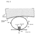
- the bag 12 is formed into a bag shape by overlapping a plurality of panels 16 and stitching peripheral edges thereof together as shown in Fig. 3.
- Reference numeral 16a designates a seam formed by a thread or the like which is used for stitching the panels 16 together.
- a protecting member 17 is assembled to a bottom surface of the seat cushion 15.
- the protecting member 17 has a sheet shape formed of rubber or synthetic resin, and is secured to the seat cushion 15 by suitable securing means such as bonding, adhering, flat fastener, stitching, hooking or the like.
- the protecting member 17 is provided substantially entirely on the bottom surface of the seat cushion 15. However, it may be provided only an inflatable area of the bag 12.
- the inflator 13 in a rod shape is arranged in the bag 12.
- the inflator 13 extends so that the longitudinal direction thereof is oriented in the direction of the width of the vehicle.
- the inflator 13 includes a gas injection port (not shown) on a side peripheral surface thereof so as to inject gas in the radial direction from the gas injection ports.
- a retainer 18 for securing the inflator 13 to the seat pan 8 is connected to the inflator 13.
- a stud bolt 18a is projected from the retainer 18. The stud bolt 18a is inserted into a bolt insertion hole on a lower surface of the bag 12 and a bolt insertion hole of the seat pan 8, and the inflator 13 and the bag 12 are fixed to the seat pan 8 by securing a nut 18b.
- the bag 12 is folded so as to be flat along an upper surface of the seat pan 8 with the width in the fore-and-aft direction reduced in the normal state (when the passenger constraining apparatus is not activated). However, the bag 12 may be folded after having mounted to the seat pan 8, and may be mounted in the state of being folded in advance and mounted to the seat pan 8 in a state of being maintained in shape by a shape-holding member (not shown). The bag 12 may also be installed on the seat pan 8 in a state of being spread over the seat pan 8 without being folded.
- An operation of the passenger constraining apparatus 10 is as follows.
- the inflator 13 When the front collision of the automotive vehicle is detected, the inflator 13 is activated to inject gas, and gas from the inflator 13 inflates the bag 12. Consequently, a front portion of the seat cushion is pushed upward or knocked up from below to increase the density, so that the forward movement of a lumber part of a passenger is prevented or constrained.
- the protecting member 17 is provided on the bottom surface of the seat cushion 15, and hence a direct friction between the bag 12 and the seat cushion 15 does occur neither in the non-inflated state nor in the inflated state of the bag. Therefore, good durability and damage-resistant property of the bag 12 are achieved.
- a protecting member 20 may be provided between the bag 12 and the seat pan 8.
- the direct friction between the bag 12 and the seat pan 8 is prevented both in the non-inflated state and in the inflated state of the bag 12, and the durability and the damage-resistant property of the bag 12 is improved.
- a seat cushion is installed on the upper side of the bag 12.
- the protecting members 17, 20 may be provided on the upper side and a lower side of the bag 12 respectively.
- the inflator 13 is provided inside the bag 12. However, it is also possible to provide the inflator outside the bag so that gas is introduced into the bag via a duct or the like.
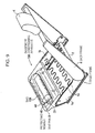
- Fig. 6 and Fig. 7 illustrate perspective views of a seat frame provided with the passenger constraining apparatus according to another embodiment.
- Fig. 6 shows a state before mounting the protecting member
- Fig. 7 shows a state after mounting the protecting member.
- Fig. 8 is a cross-sectional view taken along the line VIII-VIII in Fig. 7,
- Fig. 9 is a perspective view of the frame of the seat in a state in which the bag of the passenger constraining apparatus is inflated.
- a passenger constraining apparatus 1 0A in this embodiment is configured in such a manner that an inflator 13A is arranged outside a bag 12A, so that gas is introduced into the bag 12A from the inflator 13A via a duct (pipe) 30.
- the bag 12A is arranged on the seat pan 8 in a state of being extended in the lateral direction.
- lug shaped fixing strips 12a are provided on left and right end sides of the bag 12A, and these fixing strips 12a are secured to the seat pan 8 with hooking members 31 such as bolts respectively so that the bag 12A is fixed.
- a duct receiving port (reference numeral is not provided) is provided at one end side of the bag 12A, and an end of the duct 30 is connected to the duct receiving port.
- the inflator 13A is of a substantially rod-shape in this embodiment, and has a configuration in which a gas injection port (not shown) is provided at axial one end side thereof. The other end of the duct 30 is connected to the gas injection port of the inflator 13A. As shown in Fig. 6, in this embodiment, the inflator 13A is installed on the seat pan 8 so as to be adjacent to the bag 12A, and the duct 30 is arranged along the upper surface of the seat pan 8.
- the bag 12A, the duct 30, and the inflator 13A are covered by a protecting member 40.
- the protecting member 40 is formed into the shape of a no-bottom container having a main plate portion 41 that covers the bag 12A, the duct 30, and the inflator 13A continuously from above the seat pan 8 (however, only the bag 12A is shown in Fig. 8, hereinafter) and a surrounding wall portion 42 that extends downward from a peripheral edge portion of the main plate portion 41 for surrounding a periphery of the bag 12A, the duct 30 and the inflator 13A continuously for integrally storing the bag 12A, the duct 30 and the inflator 13A.
- the main plate portion 41 is adapted to be torn when the airbag 12A is inflated. More specifically, a tear line 43 (Fig. 8) for guiding tearing of the main plate portion 41 is formed along an outer periphery of an area of the main plate portion 41 that opposes the bag 12A according to this embodiment.
- the main plate portion 41 is torn along the tear line 43 by the inflating pressure of the bag 12A, and the area of the main plate portion 41 that opposes the bag 12A starts to open by being pushed by the inflating bag 12A.
- a portion indicated by the double-dashed chain line in Fig. 8 designates an area of the main plate portion 41 that opposes the bag 12A, which is brought into an opened state by being pushed by the inflating bag 12A.
- a hooking member 45 for securing the protecting member 40 to the seat pan 8 is provided at a lower portion of the surrounding wall portion 42.
- the hooking member 45 is a claw-or hook-shaped resilient member extending downward from a lower end of the surrounding wall portion 42, and the hooking member 45 resiliently engages a hooking member engaging hole 8b provided on the seat pan 8, so that the protecting member 40 is secured to the seat pan 8 as shown in Fig. 8.
- the plurality of hooking members 45 are arranged at different points in the extending direction of the surrounding wall portion 42 as important spots (reference numeral is not shown in Fig. 6).
- a configuration of the hooking member 45 that is, a method of securing the protecting member 40 to the seat pan 8 is not limited thereto.
- the protecting member 40 is formed of synthetic resin, and the main plate portion 41, the surrounding wall portion 42, and the respective hooking members 45 are integrally formed.
- the material of the protecting member 40 is not limited thereto, and may be formed of various materials such as rubber or metal thin plate.
- the inflator 13A When the front collision of the automotive vehicle is detected, the inflator 13A is activated to inject gas, and the gas from the inflator 13A is introduced into the bag 12A via the duct 30.
- the bag 12A starts inflation by the gas from the inflator 13A and the protecting member 40 is torn by the inflating pressure of the bag 12A. Then, the bag 12A pushes and opens the protecting member 40 to protrude upward. Consequently, the density is increased by the front portion of the seat cushion pushed upward or knocked upward from below, and hence the forward movement of the lumber part of the passenger is prevented or constrained.
- the protecting member 40 covers the upper side of the bag 12A when the bag 12A is not inflated, direct contact between the bag 12A and the seat cushion does not exist, and hence good durability and damage-resistant property of the bag 12A are achieved.
- the inflator 13A and the duct 30 arranged outside the bag 12A are also covered by the protecting member 40, good durability and damage-resistant property is also achieved for these members.
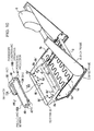
- Fig. 10 and Fig. 11 are perspective view of a frame of a seat provided with the passenger constraining apparatus according to still another embodiment.
- Fig. 10 shows a state before the passenger constraining apparatus is installed
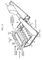
- Fig. 11 is a state after the passenger constraining apparatus is installed.
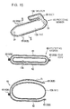
- Fig. 12 is a cross-sectional view taken along the line XII-XII in Fig. 9, and
- Fig. 13 is a cross-sectional view taken along the line XIII-XIII in Fig. 10.
- the bag 12A is secured to the seat pan 8 by the hooking members 31 respectively via the fixing strips 12a at the left and right end sides thereof.
- Reference numeral 12b in Fig. 13 designates openings provided on the respective fixing strips 12a for inserting the hooking members 31.
- Reference numerals 8a in Fig. 10 designate openings provided on the seat pan 8 for inserting the hooking members 31.
- the hooking members 31 are bolts, and nuts 8c to which the bolts are screwed on are secured to the openings 8a.
- the inflator 13A is arranged outside the bag 12A, and the inflator 13A and the bag 12A are connected by the duct 30.
- the bag 12A, the duct 30, and the inflator 13A are integrally covered by a protecting member 40A.
- the protecting member 40A in this embodiment is formed into the shape of a no-bottom container having the main plate portion 41 that covers the bag 12A, the duct 30, and the inflator 13A continuously from above the seat pan 8 (however, only the bag 12A is shown in Fig. 12, hereinafter) and the surrounding wall portion 42 that extends downward surrounds from the peripheral edge portion of the main plate portion 41 for surrounding the periphery of the bag 12A, the duct 30, and the inflator 13A continuously.
- openings 46 for inserting the hooking members 31 are provided at the left and right end sides of an area of the main plate portion 41 that opposes the bag 12A in the overlapping relation with the openings 12b (Fig. 13) of the both fixing strips 12a of the bag 12A.
- boss portions 46a to be fitted into the openings 12b of the respective fixing strips 12a are formed by depressing a peripheral edge portions of the respective openings 46 downward.
- the bag 12A is positioned in the protecting member 40A by engaging the boss portions 46a on both sides of the protecting member 40A with the opening 12b on both sides of the bag 12A, respectively.
- the height of projection of the boss portion 46a from a back surface of the main plate portion 41 is larger than the vertical thickness of the respective fixing strips 12a.
- a projection 47 for positioning the protecting member 40A with respect to the seat pan 8 is provided so as to project from a lower end of the surrounding wall portion 42, and the seat pan 8 is provided with a projection engaging hole 8b', with which the projection 47 engages, in the overlapping relation with respect to the projection 47 when the protecting member 40A is arranged in a prescribed position (when they are arranged so that the openings 46, 8a of the protecting member 40A and the seat pan 8 match with respect to each other).
- overhanging portions 48 which protrude on a lower side of the bag 12A, the duct 30 and the inflator 13A which are arranged in the protecting member 40A, are provided so as to project from a lower end side of the surrounding wall portion 42. With the provision of the overhanging portions 48, the bag 12A, the duct 30 and the inflator 13A are retained in the protecting member 40A.
- FIG. 10B Other configurations of the passenger constraining apparatus 10B are the same as those of the passenger constraining apparatus 10A in Figs. 6 to 9 described above, and the same parts in Figs. 10 to 12 are represented by the same reference numerals as in Figs. 6 to 9.
- the inflator 13A is connected to the bag 12A via the duct 30 in advance, and these members are assembled into the protecting member 40 together.
- the overhanging portions 48 of the protecting member 40A are led to the lower side of the bag 12A, the duct 30 and the inflator 13A to prevent these members from falling out from the protecting member 40A, and then the boss portions 46a on the both sides of the protecting member 40A are engaged with the openings 12b on the fixing strips 12a on the both sides of the bag 12A respectively to position the bag 12A.
- the protecting member 40A is arranged on the seat pan 8.
- the positioning projection 47 of the protecting member 40A is engaged with the projection engaging hole 8b' of the seat pan 8 for positioning the protecting member 40A.
- the hooking members (bolts) 31 are inserted into the openings 46, 8a of the protecting member 40A and the seat pan 8 and tightened with the nuts 8c. Accordingly, the protecting member 40A and the bag 12A (and the duct 30 and the inflator 13A) are integrally secured to the seat pan 8.
- the overhanging portions 48 which protrude to the lower side of the bag 12A, the duct 30 and the inflator 13A are provided so as to prevent these members from falling out from the protecting member 40A, these overhanging portions 48 may be omitted.
- Fig. 14 is a vertical cross-sectional view of the protecting member 40B configured in this manner.
- the protecting member 40B includes an upper main plate portion 41 for covering the upper side of the bag 12A, a lower main plate portion 49 for covering the lower side of the bag 12A, and a surrounding wall portion 42 for surrounding the periphery of the bag 12A.
- the upper and lower main plate portions 41, 49 and the surrounding wall portion 42 are integrally formed and the upper main plate portion 41 is adapted to be torn along the tear line 43 when the bag 12A is inflated.
- FIG. 14 Other configurations of the protecting member 40B are the same as the protecting members 40, 40A in the respective embodiments shown in Fig. 6 to Fig. 13 described above, and the reference numerals in Fig. 14 which are the same as those in Fig. 6 to Fig. 13 designate the same parts.
- the bag 12A does not come into contact with both of the seat cushion and the seat pan, and hence good durability and the damage-resistant property of the bag 12A are achieved.
- the respective embodiments in Fig. 6 to Fig. 14 described above are configured in such a manner that the protecting member is torn along the tear line when the bag is inflated.
- the method of opening the protecting member is not limited thereto.
- Fig. 15 is an explanatory drawing of a protecting member 60 configured in this manner.
- Fig. 15(a) is a perspective view showing a state in which the bag 12A (and the inflator 13A, and so on) is covered by the protecting member 60;
- Fig. 15(b) is a cross-sectional view taken along the line B-B in (a);
- Fig. 15(c) is a cross-sectional view showing the similar portion of the same drawing (b) when the bag is inflated.
- the protecting member 60 includes an upper covering member 61 for covering the upper side of the bag 12A, the duct 30, and the inflator 13A, and a lower covering member 62 for covering the lower side of the same.
- the covering members 61, 62 include sheets or the like formed of cloth material, rubber, or synthetic resin respectively, and are formed into a bag-shaped member that includes the bag 12A, the duct 30 and the inflator 13A by being stitched together by seams 63 (63A, 63B) of threads or the like along the peripheral edges thereof.
- a portion of the seam 63 which is formed by stitching side edges of the covering members 61, 62 along rear edge portions of the bag 12A (the fore-and-aft direction corresponds to the fore-and-aft direction when the bag 12A is installed in the seat) is a tear seam 63B with low strength.
- the tear seam 63B is configured to be torn by the inflating pressure of the bag 12A and release the connection between the covering members 61, 62 when the bag 12A is inflated.
- the remaining portion of the seam 63 is a strong seam 63A which is not torn even when the bag 12A is inflated.
- the bag 12A when the bag 12A is in the non-inflated state, the upper side and the lower side of the bag 12A, the duct 30, and the inflator 13A are covered by the upper covering member 61 and the lower covering member 62 of the protecting member 60, respectively. Therefore, the bag 12A, the duct 30 and the inflator 13A come into contact neither with the seat cushion nor the seat pan, and hence good durability and the damage-resistant property are achieved.
- the tear seam 63B is broken by the inflating pressure of the bag 12A, and connection between the covering members 61, 62 are released. Accordingly, the covering members 61, 62 are separated and inflation of the bag 12A is accommodated.
- the protecting member is adapted to be torn when the bag is inflated.
- the bag, the inflator arranged outside the bag, and the duct that connects the bag and the inflator are covered integrally by the protecting member.
- these members may be covered by separate protecting members.
- at least the bag must simply be covered by the protecting member.
- a configuration in which the inflator is arranged on the back side of the seat pan and only the bag is arranged on the seat pan and covered by the protecting member is also applicable.
- the protecting member for covering the bag can be provided also in a mode in which the inflator is arranged in the interior of the bag.
Abstract
Description
- The present invention relates to a passenger constraining apparatus for constraining a passenger on a seat of a vehicle such as an automotive vehicle upon collision and, more specifically, to a passenger constraining apparatus configured to constrain a lumber part of the passenger upon front collision and prevent a passenger's body from moving forward or downward.
- In a system for constraining a passenger in an automotive vehicle upon collision,
JP-A-10-217818 - Fig. 5 is a vertical cross-sectional view taken in the fore-and-aft direction of a seat showing the passenger constraining apparatus in the same publication. In a front portion of the seat, an
airbag 104 is arranged between a cushion frame (seat pan) 100 and aseat pad 102. Thisairbag 104 extends in the direction of the lateral width of the seat, and is inflatable by aninflator 106. An upper surface of theseat pad 102 is covered by atrim cover 108, and the passenger sits thereon. - When the
inflator 106 is activated upon collision, theairbag 104 is inflated, and a front portion of theseat pad 102 is pushed upward or knocked up from below to increase the density, so that the forward movement of the passenger's body is prevented (including "constrained"). - In the passenger constraining apparatus having a bag arranged under the seat cushion, it is an object of the present invention to improve durability of the bag as descried above. This object is achieved with the features of the claims.
- A passenger constraining apparatus according to
Claim 1 is a passenger constraining apparatus including a bag being arranged between a seat cushion and a member under the seat cushion so as to extend in the direction of the lateral width of a seat and being capable of inflating so as to press the seat cushion from the lower side, and a gas generator for inflating the bag in case of vehicle emergency, characterized in that a protecting member for protecting the bag is provided at least one of between the bag and the seat cushion and between the bag and the member under the seat cushion. - In
Claim 1, the passenger constraining apparatus according to Claim 2 is characterized in that the protecting member is assembled to a bottom surface of the seat cushion. - In
Claim 1 or 2, the passenger constraining apparatus according to Claim 3 is characterized in that the protecting member is a sheet shape formed of rubber of resin. - In
Claim 1, the passenger constraining apparatus according toClaim 4 is characterized in that the protecting member covers at least an upper side of the bag, and the protecting member is adapted to be opened by an inflating pressure of the bag to allow the bag to inflate. - In
Claim 4, the passenger constraining apparatus in Claim 5 is characterized in that the bag is assembled to the protecting member, and the protecting member is mounted to the member under the seat cushion. - In Claim 5, the passenger constraining apparatus according to Claim 6 is characterized in that the protecting member and the bag are secured to the member under the seat cushion by a common hooking member.
- In
Claim 1, the passenger constraining apparatus according to Claim 7 is characterized in that the protecting member surrounds the bag, the protecting member is formed of an expandable material, and the protecting member is expanded by the inflating pressure of the bag to allow the bag to inflate. - In the present invention, the protecting member is provided between the bag and the seat cushion or the member under the seat cushion, and hence direct friction between the bag and these members are avoided, so that the durability of the bag is improved.
- In the case in which the protecting member is assembled to the bottom surface of the seat cushion as in Claim 2, the installation of the protecting member is also achieved by mounting the seat cushion to the seat. Therefore, assembly of the seat is simplified.
- As in Claim 3, the protecting member is preferably a sheet-shaped material formed of rubber or resin.
- In the mode in
Claim 4, since the protecting member covers at least the upper side of the bag when the bag is not inflated, the direct friction between the bag and the seat cushion is avoided, and hence good durability of the bag is achieved. When the bag is inflated, the protecting member is opened, and the seat cushion is pressed by the inflating bag. - By assembling the bag to the protecting member and the mounting the protecting member to the member under the seat cushion as in Claim 5, the mounting work of the protecting member and the bag to the member under the seat cushion can be simplified.
- With the configuration in which the protecting member and the bag to the member are secured to the member under the seat cushion with a common hooking member as in Claim 6, the mounting work can further be facilitated, and the reduction of the cost of the members can also be achieved.
- In the mode in Claim 7, the protecting member formed of the expandable material surrounds the bag, and hence the protecting member is expanded when the bag is inflated. Therefore, the configuration is simplified.
- Referring now to the drawings, embodiments of the present invention will be described:
- Fig. 1 is a perspective view of a frame of a seat provided with a passenger constraining apparatus according to an embodiment of the present invention when a bag is not inflated, and showing a seat cushion along a vertical cross section;
- Fig. 2 is a perspective view of a state in which the seat cushion is removed from Fig. 1;
- Fig. 3 is a cross-sectional view taken along the line III-III in Fig. 1 when the bag is inflated;
- Fig. 4 is a perspective view showing another embodiment;
- Fig. 5 is a vertical cross-sectional view taken in the fore-and-aft direction of a seat showing the passenger constraining apparatus in the related art;
- Fig. 6 is a perspective view of a frame of a seat provided with a passenger constraining apparatus according to still another embodiment before a protecting member is mounted;
- Fig. 7 is a perspective view of the passenger constraining apparatus in Fig. 6 after the protecting member is mounted;
- Fig. 8 is a cross-sectional view taken along the line VIII-VIII in Fig. 7;
- Fig. 9 is a perspective view of the passenger constraining apparatus in Fig. 6 when the bag is inflated;
- Fig. 10 is a perspective view of a frame of a seat provided with a passenger constraining apparatus according to still another embodiment in a state before the passenger constraining apparatus is mounted;
- Fig. 11 is a perspective view of the frame of the seat in Fig. 10 in a state after the passenger constraining apparatus is mounted;
- Fig. 12 is a cross-sectional view taken along the line XII-XII in Fig. 10;
- Fig. 13 is a cross-sectional view taken along the line XIII-XIII in Fig. 11;
- Fig. 14 is a vertical cross-sectional view of a bag portion of the passenger constraining apparatus according to still another embodiment; and
- Fig. 15 is a pattern diagram of the passenger constraining apparatus according to still another embodiment.
- According to Figs. 1 to 4, the frame constituting the seat of an automotive vehicle includes a
base frame 1, and aback frame 4 connected to thebase frame 1 rotatably via a spindle 2 and a reclining device (not shown). A head rest 6 is mounted to an upper portion of theback frame 4. Thebase frame 1 includes left andright side frames seat pan 8 is provided so as to extend between front portions of theside frames - A
seat cushion 15 and a seatback (not shown) formed of urethane of the like are mounted to thebase frame 1 and theback frame 4. Theseat pan 8 is arranged under a front portion of theseat cushion 15.Reference numeral 1d in Fig. 1 shows a spring which rotatably supports theseat cushion 15. - A
passenger constraining apparatus 10 includes abag 12 which is arranged above theseat pan 8 and is inflatable so as to push the front portion of theseat cushion 15 from the lower side, and an inflator (gas generator) 13 for inflating thebag 12. Thebag 12 extends laterally (in the direction of the width of the vehicle) of theseat pan 8. Both end sides of thebag 12 in terms of the lateral direction are secured to theseat pan 8 withbolts 14. Theseat cushion 15 is installed on an upper side of thebag 12. - In this embodiment, the
bag 12 is formed into a bag shape by overlapping a plurality ofpanels 16 and stitching peripheral edges thereof together as shown in Fig. 3.Reference numeral 16a designates a seam formed by a thread or the like which is used for stitching thepanels 16 together. - In this embodiment, a protecting
member 17 is assembled to a bottom surface of theseat cushion 15. The protectingmember 17 has a sheet shape formed of rubber or synthetic resin, and is secured to theseat cushion 15 by suitable securing means such as bonding, adhering, flat fastener, stitching, hooking or the like. In this embodiment, the protectingmember 17 is provided substantially entirely on the bottom surface of theseat cushion 15. However, it may be provided only an inflatable area of thebag 12. - In this embodiment, the
inflator 13 in a rod shape is arranged in thebag 12. Theinflator 13 extends so that the longitudinal direction thereof is oriented in the direction of the width of the vehicle. Theinflator 13 includes a gas injection port (not shown) on a side peripheral surface thereof so as to inject gas in the radial direction from the gas injection ports. - As shown in Fig. 3, a
retainer 18 for securing theinflator 13 to theseat pan 8 is connected to theinflator 13. Astud bolt 18a is projected from theretainer 18. Thestud bolt 18a is inserted into a bolt insertion hole on a lower surface of thebag 12 and a bolt insertion hole of theseat pan 8, and theinflator 13 and thebag 12 are fixed to theseat pan 8 by securing anut 18b. - The
bag 12 is folded so as to be flat along an upper surface of theseat pan 8 with the width in the fore-and-aft direction reduced in the normal state (when the passenger constraining apparatus is not activated). However, thebag 12 may be folded after having mounted to theseat pan 8, and may be mounted in the state of being folded in advance and mounted to theseat pan 8 in a state of being maintained in shape by a shape-holding member (not shown). Thebag 12 may also be installed on theseat pan 8 in a state of being spread over theseat pan 8 without being folded. - An operation of the
passenger constraining apparatus 10 is as follows. - When the front collision of the automotive vehicle is detected, the
inflator 13 is activated to inject gas, and gas from the inflator 13 inflates thebag 12. Consequently, a front portion of the seat cushion is pushed upward or knocked up from below to increase the density, so that the forward movement of a lumber part of a passenger is prevented or constrained. - In this
passenger constraining apparatus 10, the protectingmember 17 is provided on the bottom surface of theseat cushion 15, and hence a direct friction between thebag 12 and theseat cushion 15 does occur neither in the non-inflated state nor in the inflated state of the bag. Therefore, good durability and damage-resistant property of thebag 12 are achieved. - In the present invention, a protecting
member 20 may be provided between thebag 12 and theseat pan 8. In this arrangement, the direct friction between thebag 12 and theseat pan 8 is prevented both in the non-inflated state and in the inflated state of thebag 12, and the durability and the damage-resistant property of thebag 12 is improved. Although not shown in Fig. 4, a seat cushion is installed on the upper side of thebag 12. - In the present invention, the protecting
members bag 12 respectively. - In the above-described embodiment, the
inflator 13 is provided inside thebag 12. However, it is also possible to provide the inflator outside the bag so that gas is introduced into the bag via a duct or the like. - Fig. 6 and Fig. 7 illustrate perspective views of a seat frame provided with the passenger constraining apparatus according to another embodiment. Fig. 6 shows a state before mounting the protecting member, and Fig. 7 shows a state after mounting the protecting member. Fig. 8 is a cross-sectional view taken along the line VIII-VIII in Fig. 7, and Fig. 9 is a perspective view of the frame of the seat in a state in which the bag of the passenger constraining apparatus is inflated.
- A
passenger constraining apparatus 1 0A in this embodiment is configured in such a manner that aninflator 13A is arranged outside abag 12A, so that gas is introduced into thebag 12A from theinflator 13A via a duct (pipe) 30. - In this embodiment as well, the
bag 12A is arranged on theseat pan 8 in a state of being extended in the lateral direction. In this embodiment, lug shaped fixingstrips 12a are provided on left and right end sides of thebag 12A, and these fixingstrips 12a are secured to theseat pan 8 with hookingmembers 31 such as bolts respectively so that thebag 12A is fixed. - In this embodiment, a duct receiving port (reference numeral is not provided) is provided at one end side of the
bag 12A, and an end of theduct 30 is connected to the duct receiving port. - The
inflator 13A is of a substantially rod-shape in this embodiment, and has a configuration in which a gas injection port (not shown) is provided at axial one end side thereof. The other end of theduct 30 is connected to the gas injection port of theinflator 13A. As shown in Fig. 6, in this embodiment, theinflator 13A is installed on theseat pan 8 so as to be adjacent to thebag 12A, and theduct 30 is arranged along the upper surface of theseat pan 8. - As shown in Fig. 7, the
bag 12A, theduct 30, and theinflator 13A are covered by a protectingmember 40. As shown in Fig. 8, in this embodiment, the protectingmember 40 is formed into the shape of a no-bottom container having amain plate portion 41 that covers thebag 12A, theduct 30, and theinflator 13A continuously from above the seat pan 8 (however, only thebag 12A is shown in Fig. 8, hereinafter) and a surroundingwall portion 42 that extends downward from a peripheral edge portion of themain plate portion 41 for surrounding a periphery of thebag 12A, theduct 30 and theinflator 13A continuously for integrally storing thebag 12A, theduct 30 and theinflator 13A. - The
main plate portion 41 is adapted to be torn when theairbag 12A is inflated. More specifically, a tear line 43 (Fig. 8) for guiding tearing of themain plate portion 41 is formed along an outer periphery of an area of themain plate portion 41 that opposes thebag 12A according to this embodiment. When thebag 12A is inflated, themain plate portion 41 is torn along thetear line 43 by the inflating pressure of thebag 12A, and the area of themain plate portion 41 that opposes thebag 12A starts to open by being pushed by the inflatingbag 12A. - A portion indicated by the double-dashed chain line in Fig. 8 (reference numeral 44) designates an area of the
main plate portion 41 that opposes thebag 12A, which is brought into an opened state by being pushed by the inflatingbag 12A. - A hooking
member 45 for securing the protectingmember 40 to theseat pan 8 is provided at a lower portion of the surroundingwall portion 42. In this embodiment, the hookingmember 45 is a claw-or hook-shaped resilient member extending downward from a lower end of the surroundingwall portion 42, and the hookingmember 45 resiliently engages a hookingmember engaging hole 8b provided on theseat pan 8, so that the protectingmember 40 is secured to theseat pan 8 as shown in Fig. 8. As shown in Fig. 6, the plurality of hookingmembers 45 are arranged at different points in the extending direction of the surroundingwall portion 42 as important spots (reference numeral is not shown in Fig. 6). - However, a configuration of the hooking
member 45, that is, a method of securing the protectingmember 40 to theseat pan 8 is not limited thereto. - In this embodiment, the protecting
member 40 is formed of synthetic resin, and themain plate portion 41, the surroundingwall portion 42, and the respective hookingmembers 45 are integrally formed. However, the material of the protectingmember 40 is not limited thereto, and may be formed of various materials such as rubber or metal thin plate. - Other configurations of this embodiment are the same as those in the above-descried embodiment, and the same parts are represented by the same reference numerals.
- An operation of the passenger constraining apparatus 10A in this configuration is as follows.
- When the front collision of the automotive vehicle is detected, the
inflator 13A is activated to inject gas, and the gas from theinflator 13A is introduced into thebag 12A via theduct 30. Thebag 12A starts inflation by the gas from theinflator 13A and the protectingmember 40 is torn by the inflating pressure of thebag 12A. Then, thebag 12A pushes and opens the protectingmember 40 to protrude upward. Consequently, the density is increased by the front portion of the seat cushion pushed upward or knocked upward from below, and hence the forward movement of the lumber part of the passenger is prevented or constrained. - In the passenger constraining apparatus 10A, since the protecting
member 40 covers the upper side of thebag 12A when thebag 12A is not inflated, direct contact between thebag 12A and the seat cushion does not exist, and hence good durability and damage-resistant property of thebag 12A are achieved. - In this embodiment, since the
inflator 13A and theduct 30 arranged outside thebag 12A are also covered by the protectingmember 40, good durability and damage-resistant property is also achieved for these members. - Fig. 10 and Fig. 11 are perspective view of a frame of a seat provided with the passenger constraining apparatus according to still another embodiment. Fig. 10 shows a state before the passenger constraining apparatus is installed, and Fig. 11 is a state after the passenger constraining apparatus is installed. Fig. 12 is a cross-sectional view taken along the line XII-XII in Fig. 9, and Fig. 13 is a cross-sectional view taken along the line XIII-XIII in Fig. 10.
- In a
passenger constraining apparatus 10B in this embodiment, thebag 12A is secured to theseat pan 8 by the hookingmembers 31 respectively via the fixing strips 12a at the left and right end sides thereof.Reference numeral 12b in Fig. 13 designates openings provided on the respective fixing strips 12a for inserting the hookingmembers 31.Reference numerals 8a in Fig. 10 designate openings provided on theseat pan 8 for inserting the hookingmembers 31. As shown in Fig. 13, in this embodiment, the hookingmembers 31 are bolts, andnuts 8c to which the bolts are screwed on are secured to theopenings 8a. - In this embodiment as well, the
inflator 13A is arranged outside thebag 12A, and theinflator 13A and thebag 12A are connected by theduct 30. Thebag 12A, theduct 30, and theinflator 13A are integrally covered by a protectingmember 40A. - As shown in Fig. 12, the protecting
member 40A in this embodiment is formed into the shape of a no-bottom container having themain plate portion 41 that covers thebag 12A, theduct 30, and theinflator 13A continuously from above the seat pan 8 (however, only thebag 12A is shown in Fig. 12, hereinafter) and the surroundingwall portion 42 that extends downward surrounds from the peripheral edge portion of themain plate portion 41 for surrounding the periphery of thebag 12A, theduct 30, and theinflator 13A continuously. - In this embodiment, as shown in Fig. 10,
openings 46 for inserting the hookingmembers 31 are provided at the left and right end sides of an area of themain plate portion 41 that opposes thebag 12A in the overlapping relation with theopenings 12b (Fig. 13) of the both fixingstrips 12a of thebag 12A. - As shown in Fig. 13, in this embodiment,
boss portions 46a to be fitted into theopenings 12b of therespective fixing strips 12a are formed by depressing a peripheral edge portions of therespective openings 46 downward. Thebag 12A is positioned in the protectingmember 40A by engaging theboss portions 46a on both sides of the protectingmember 40A with theopening 12b on both sides of thebag 12A, respectively. The height of projection of theboss portion 46a from a back surface of themain plate portion 41 is larger than the vertical thickness of therespective fixing strips 12a. - In this embodiment, a
projection 47 for positioning the protectingmember 40A with respect to theseat pan 8 is provided so as to project from a lower end of the surroundingwall portion 42, and theseat pan 8 is provided with aprojection engaging hole 8b', with which theprojection 47 engages, in the overlapping relation with respect to theprojection 47 when the protectingmember 40A is arranged in a prescribed position (when they are arranged so that theopenings member 40A and theseat pan 8 match with respect to each other). - As shown in Fig. 12, in this embodiment, overhanging
portions 48, which protrude on a lower side of thebag 12A, theduct 30 and theinflator 13A which are arranged in the protectingmember 40A, are provided so as to project from a lower end side of the surroundingwall portion 42. With the provision of the overhangingportions 48, thebag 12A, theduct 30 and theinflator 13A are retained in the protectingmember 40A. - Other configurations of the
passenger constraining apparatus 10B are the same as those of the passenger constraining apparatus 10A in Figs. 6 to 9 described above, and the same parts in Figs. 10 to 12 are represented by the same reference numerals as in Figs. 6 to 9. - A procedure of installing the
passenger constraining apparatus 10B in this configuration to theseat pan 8 will be described below. - Firstly, the
inflator 13A is connected to thebag 12A via theduct 30 in advance, and these members are assembled into the protectingmember 40 together. In this case, the overhangingportions 48 of the protectingmember 40A are led to the lower side of thebag 12A, theduct 30 and theinflator 13A to prevent these members from falling out from the protectingmember 40A, and then theboss portions 46a on the both sides of the protectingmember 40A are engaged with theopenings 12b on the fixing strips 12a on the both sides of thebag 12A respectively to position thebag 12A. - Subsequently, the protecting
member 40A is arranged on theseat pan 8. In this case, thepositioning projection 47 of the protectingmember 40A is engaged with theprojection engaging hole 8b' of theseat pan 8 for positioning the protectingmember 40A. Then, the hooking members (bolts) 31 are inserted into theopenings member 40A and theseat pan 8 and tightened with the nuts 8c. Accordingly, the protectingmember 40A and thebag 12A (and theduct 30 and the inflator 13A) are integrally secured to theseat pan 8. - In this
passenger constraining apparatus 10B, since thebag 12A, theduct 30 and theinflator 13A are assembled to the interior of the protectingmember 40A in advance into a unit, the installation work to theseat pan 8 is easily. - In this
passenger constraining apparatus 10B, since the protectingmember 40A and thebag 12A are secured to theseat pan 8 by the common hookingmembers 31 as described above, the securing work to theseat pan 8 is also simple. - In this embodiment, although the overhanging
portions 48 which protrude to the lower side of thebag 12A, theduct 30 and theinflator 13A are provided so as to prevent these members from falling out from the protectingmember 40A, these overhangingportions 48 may be omitted. - The protecting
members bag 12A. However, in the present invention, it is also possible to cover both of the upper side and the lower side of the bag by the protecting member. Fig. 14 is a vertical cross-sectional view of the protectingmember 40B configured in this manner. - The protecting
member 40B includes an uppermain plate portion 41 for covering the upper side of thebag 12A, a lowermain plate portion 49 for covering the lower side of thebag 12A, and a surroundingwall portion 42 for surrounding the periphery of thebag 12A. In this embodiment, the upper and lowermain plate portions wall portion 42 are integrally formed and the uppermain plate portion 41 is adapted to be torn along thetear line 43 when thebag 12A is inflated. - Other configurations of the protecting
member 40B are the same as the protectingmembers - In the protecting
member 40B, not only the upper side of thebag 12A is covered by the uppermain plate portion 41, but also the lower side thereof is covered by the lowermain plate portion 49. Therefore, thebag 12A does not come into contact with both of the seat cushion and the seat pan, and hence good durability and the damage-resistant property of thebag 12A are achieved. - The respective embodiments in Fig. 6 to Fig. 14 described above are configured in such a manner that the protecting member is torn along the tear line when the bag is inflated. However, the method of opening the protecting member is not limited thereto. For example, it is also possible to configure in such a manner that the portion of the protecting member for covering the upper side of the bag and the portion for covering the lower side of the protecting member are provided separately so that these members are connected when the bag is not inflated and the protecting member is opened by separation of these members when the bag is inflated.
- Fig. 15 is an explanatory drawing of a protecting
member 60 configured in this manner. Fig. 15(a) is a perspective view showing a state in which thebag 12A (and theinflator 13A, and so on) is covered by the protectingmember 60; Fig. 15(b) is a cross-sectional view taken along the line B-B in (a); and Fig. 15(c) is a cross-sectional view showing the similar portion of the same drawing (b) when the bag is inflated. - The protecting
member 60 includes anupper covering member 61 for covering the upper side of thebag 12A, theduct 30, and theinflator 13A, and alower covering member 62 for covering the lower side of the same. In this embodiment, the coveringmembers bag 12A, theduct 30 and theinflator 13A by being stitched together by seams 63 (63A, 63B) of threads or the like along the peripheral edges thereof. - In this embodiment, a portion of the
seam 63 which is formed by stitching side edges of the coveringmembers bag 12A (the fore-and-aft direction corresponds to the fore-and-aft direction when thebag 12A is installed in the seat) is atear seam 63B with low strength. Thetear seam 63B is configured to be torn by the inflating pressure of thebag 12A and release the connection between the coveringmembers bag 12A is inflated. The remaining portion of theseam 63 is astrong seam 63A which is not torn even when thebag 12A is inflated. - Other configurations in this embodiment are the same as those in the respective embodiments shown in Fig. 6 to Fig. 14 described above.
- In this embodiment, when the
bag 12A is in the non-inflated state, the upper side and the lower side of thebag 12A, theduct 30, and theinflator 13A are covered by theupper covering member 61 and thelower covering member 62 of the protectingmember 60, respectively. Therefore, thebag 12A, theduct 30 and theinflator 13A come into contact neither with the seat cushion nor the seat pan, and hence good durability and the damage-resistant property are achieved. - When the
bag 12A starts to be inflated, as shown in Fig. 15(c), thetear seam 63B is broken by the inflating pressure of thebag 12A, and connection between the coveringmembers members bag 12A is accommodated. - The respective embodiments described above are illustrative only, and the present invention is not limited to the above-described embodiments.
- For example, in the respective embodiments in Fig. 6 to Fig. 15 described above, the protecting member is adapted to be torn when the bag is inflated. However, in the present invention, it is also possible to cover the bag by the protecting member formed of expansible member so that the protecting member is an expanded in association with the inflation of the bag when the bag is inflated.
- In the respective embodiments shown in Fig. 6 to Fig. 15 described above, it is also possible to provide a protecting member for covering the lower surface of the seat cushion or a protecting member for covering the upper surface of the member under the seat cushion (seat pan or the like) as in the embodiments in Fig. 1 to Fig. 4 in addition to the protecting member for covering the bag (and the inflator and so on).
- In the respective embodiments shown in Fig. 6 to Fig. 15 described above, the bag, the inflator arranged outside the bag, and the duct that connects the bag and the inflator are covered integrally by the protecting member. However, these members may be covered by separate protecting members. In the present invention, at least the bag must simply be covered by the protecting member. A configuration in which the inflator is arranged on the back side of the seat pan and only the bag is arranged on the seat pan and covered by the protecting member is also applicable.
- As in the respective embodiments shown in Figs. 1 to 4, the protecting member for covering the bag can be provided also in a mode in which the inflator is arranged in the interior of the bag.
Claims (8)
- A passenger constraining apparatus comprising:a bag being arranged between a seat cushion and a member under the seat cushion so as to extend in the direction of the lateral width of a seat and being capable of inflating so as to press the seat cushion from the lower side, anda gas generator for inflating the bag in case of vehicle emergency,characterized in that a protecting member for protecting the bag is provided at least one of between the bag and the seat cushion and between the bag and the member under the seat cushion.
- The passenger constraining apparatus according to Claim 1, characterized in that the protecting member is assembled to a bottom surface of the seat cushion.
- The passenger constraining apparatus according to Claim 1 or 2, characterized in that the protecting member is a sheet shape formed of rubber of resin.
- The passenger constraining apparatus according to Claim 1, 2, or 3, characterized in that the protecting member covers at least an upper side of the bag, and the protecting member is adapted to be opened by an inflating pressure of the bag to allow the bag to inflate.
- The passenger constraining apparatus according to Claim 4, characterized in that the bag is assembled to the protecting member, and the protecting member is mounted to the member under the seat cushion.
- The passenger constraining apparatus according to Claim 5, characterized in that the protecting member and the bag are secured to the member under the seat cushion by a common hooking member.
- The passenger constraining apparatus according to Claim 1, 2, or 3, wherein characterized in that the protecting member surrounds the bag, the protecting member is formed of an expandable material, and the protecting member is expanded by the inflating pressure of the bag to allow the bag to inflate.
- The apparatus of any one of claims 1 to 7, wherein the bag is adapted to be capable to inflate so as to press a front portion of the seat cushion from the lower side.
Applications Claiming Priority (2)
| Application Number | Priority Date | Filing Date | Title |
|---|---|---|---|
| JP2005310158 | 2005-10-25 | ||
| JP2006006260A JP4715523B2 (en) | 2005-10-25 | 2006-01-13 | Crew restraint system |
Publications (3)
| Publication Number | Publication Date |
|---|---|
| EP1780074A2 true EP1780074A2 (en) | 2007-05-02 |
| EP1780074A3 EP1780074A3 (en) | 2008-01-23 |
| EP1780074B1 EP1780074B1 (en) | 2012-02-01 |
Family
ID=37821360
Family Applications (1)
| Application Number | Title | Priority Date | Filing Date |
|---|---|---|---|
| EP06121471A Expired - Fee Related EP1780074B1 (en) | 2005-10-25 | 2006-09-29 | Passenger constraining apparatus |
Country Status (3)
| Country | Link |
|---|---|
| US (1) | US7607728B2 (en) |
| EP (1) | EP1780074B1 (en) |
| JP (1) | JP4715523B2 (en) |
Families Citing this family (15)
| Publication number | Priority date | Publication date | Assignee | Title |
|---|---|---|---|---|
| JP2006199271A (en) * | 2004-12-24 | 2006-08-03 | Tkj Kk | Occupant restraint system |
| JP5078248B2 (en) * | 2005-10-28 | 2012-11-21 | タカタ株式会社 | Crew restraint system |
| JP4802660B2 (en) * | 2005-10-28 | 2011-10-26 | タカタ株式会社 | Crew restraint system |
| US20070176403A1 (en) * | 2006-02-01 | 2007-08-02 | Dennis Calderone | Air adjustable seat |
| DE102006011105B4 (en) * | 2006-03-08 | 2010-09-16 | Autoliv Development Ab | Safety arrangement in a vehicle seat |
| JP4850563B2 (en) * | 2006-04-05 | 2012-01-11 | タカタ株式会社 | Vehicle seat, vehicle, airbag module |
| DE102006017751A1 (en) * | 2006-04-11 | 2007-10-18 | Takata-Petri Ag | Airbag module |
| US7648161B2 (en) * | 2006-04-19 | 2010-01-19 | Honda Motor Co., Ltd. | Airbag device |
| JP2012016970A (en) * | 2010-07-06 | 2012-01-26 | Toyota Motor Corp | Vehicular seat built in with cushion airbag device |
| JP5594166B2 (en) * | 2011-01-28 | 2014-09-24 | 豊田合成株式会社 | Seat cushion airbag device |
| JP5545282B2 (en) * | 2011-09-30 | 2014-07-09 | 豊田合成株式会社 | Seat cushion airbag device |
| JP5958129B2 (en) * | 2012-07-12 | 2016-07-27 | 豊田合成株式会社 | Seat cushion airbag device |
| JP6089858B2 (en) * | 2013-03-26 | 2017-03-08 | 豊田合成株式会社 | Seat cushion airbag device |
| US9199560B2 (en) * | 2013-09-13 | 2015-12-01 | Ford Global Technologies, Llc | Self-adjusting seat stiffness system |
| JP6522090B2 (en) * | 2017-11-30 | 2019-05-29 | テイ・エス テック株式会社 | Vehicle seat |
Citations (2)
| Publication number | Priority date | Publication date | Assignee | Title |
|---|---|---|---|---|
| EP1550588A2 (en) * | 2003-12-24 | 2005-07-06 | Toyoda Gosei Co., Ltd. | Knee protecting airbag device |
| JP2005231624A (en) * | 2003-09-30 | 2005-09-02 | Takata Corp | Occupant crash protection device |
Family Cites Families (8)
| Publication number | Priority date | Publication date | Assignee | Title |
|---|---|---|---|---|
| US5568936A (en) * | 1995-11-08 | 1996-10-29 | Morton International, Inc. | Airbag module case for side impact airbag module |
| JP3285129B2 (en) | 1997-01-31 | 2002-05-27 | ジョンソン コントロールズ オートモーティブ システムズ株式会社 | Vehicle seat |
| GB2357466B (en) * | 1999-12-21 | 2003-04-02 | Autoliv Dev | Improvements in or relating to a vehicle seat |
| US6682141B2 (en) * | 2001-09-14 | 2004-01-27 | The Boeing Company | Seat assembly having a seat repositioning device and an associated method |
| JP3972736B2 (en) * | 2002-06-04 | 2007-09-05 | タカタ株式会社 | Crew protection device |
| JP4269826B2 (en) * | 2003-03-12 | 2009-05-27 | タカタ株式会社 | Crew protection device |
| US20050067209A1 (en) | 2003-09-30 | 2005-03-31 | Takata Corporation | Passenger protecting device |
| US20060017266A1 (en) | 2003-09-30 | 2006-01-26 | Takata Corporation | Passenger protecting device |
-
2006
- 2006-01-13 JP JP2006006260A patent/JP4715523B2/en not_active Expired - Fee Related
- 2006-09-29 EP EP06121471A patent/EP1780074B1/en not_active Expired - Fee Related
- 2006-10-24 US US11/585,502 patent/US7607728B2/en not_active Expired - Fee Related
Patent Citations (2)
| Publication number | Priority date | Publication date | Assignee | Title |
|---|---|---|---|---|
| JP2005231624A (en) * | 2003-09-30 | 2005-09-02 | Takata Corp | Occupant crash protection device |
| EP1550588A2 (en) * | 2003-12-24 | 2005-07-06 | Toyoda Gosei Co., Ltd. | Knee protecting airbag device |
Also Published As
| Publication number | Publication date |
|---|---|
| US20070090633A1 (en) | 2007-04-26 |
| JP2007145307A (en) | 2007-06-14 |
| JP4715523B2 (en) | 2011-07-06 |
| EP1780074A3 (en) | 2008-01-23 |
| US7607728B2 (en) | 2009-10-27 |
| EP1780074B1 (en) | 2012-02-01 |
Similar Documents
| Publication | Publication Date | Title |
|---|---|---|
| EP1780074B1 (en) | Passenger constraining apparatus | |
| US7322597B2 (en) | Vehicle seat assembly with separable air bag guide retainers | |
| US7290791B2 (en) | Vehicle seat assembly with air bag guide retainer | |
| US7334811B2 (en) | Vehicle seat assembly with spaced air bag guide retainers | |
| US8672352B2 (en) | Vehicle seat assembly with seat pad protection member | |
| US7134685B2 (en) | Air bag deployment arrangement | |
| US7540529B2 (en) | Vehicle seat assembly | |
| US8833852B2 (en) | Vehicle seat assembly | |
| US5398959A (en) | Panel cover door attachment for inflatable occupant restraint | |
| US7360789B2 (en) | Airbag device for front passenger's seat | |
| US6851704B2 (en) | Air bag assembly | |
| US20080284143A1 (en) | Vehicle seat having an integrated airbag module | |
| US7878589B2 (en) | Occupant restraint device | |
| WO2007055106A1 (en) | Occupant restraint device | |
| WO2007049541A1 (en) | Occupant restraint device | |
| US20140077480A1 (en) | Airbag module for a vehicle seat assembly | |
| US7377542B2 (en) | Vehicle seat side air bag system | |
| JP2023111987A5 (en) | ||
| US8662530B2 (en) | Vehicle seat assembly with rigid air bag protection member | |
| JP2007276600A (en) | Vehicle seat, vehicle, and airbag module | |
| US20060175880A1 (en) | Occupant protection device | |
| JP2007276599A (en) | Vehicle seat, vehicle, and airbag module | |
| US8752863B2 (en) | Vehicle seat assembly with air bag module having integral protection member | |
| JP2010241192A (en) | Side airbag device for vehicle | |
| JP2001213260A (en) | Side air bag |
Legal Events
| Date | Code | Title | Description |
|---|---|---|---|
| PUAI | Public reference made under article 153(3) epc to a published international application that has entered the european phase |
Free format text: ORIGINAL CODE: 0009012 |
|
| AK | Designated contracting states |
Kind code of ref document: A2 Designated state(s): AT BE BG CH CY CZ DE DK EE ES FI FR GB GR HU IE IS IT LI LT LU LV MC NL PL PT RO SE SI SK TR |
|
| AX | Request for extension of the european patent |
Extension state: AL BA HR MK YU |
|
| PUAL | Search report despatched |
Free format text: ORIGINAL CODE: 0009013 |
|
| AK | Designated contracting states |
Kind code of ref document: A3 Designated state(s): AT BE BG CH CY CZ DE DK EE ES FI FR GB GR HU IE IS IT LI LT LU LV MC NL PL PT RO SE SI SK TR |
|
| AX | Request for extension of the european patent |
Extension state: AL BA HR MK YU |
|
| RIC1 | Information provided on ipc code assigned before grant |
Ipc: B60R 21/20 20060101ALI20071220BHEP Ipc: B60N 2/42 20060101AFI20070315BHEP |
|
| 17P | Request for examination filed |
Effective date: 20080530 |
|
| 17Q | First examination report despatched |
Effective date: 20080626 |
|
| AKX | Designation fees paid |
Designated state(s): DE GB |
|
| RAP1 | Party data changed (applicant data changed or rights of an application transferred) |
Owner name: TAKATA CORPORATION |
|
| GRAP | Despatch of communication of intention to grant a patent |
Free format text: ORIGINAL CODE: EPIDOSNIGR1 |
|
| GRAS | Grant fee paid |
Free format text: ORIGINAL CODE: EPIDOSNIGR3 |
|
| GRAA | (expected) grant |
Free format text: ORIGINAL CODE: 0009210 |
|
| AK | Designated contracting states |
Kind code of ref document: B1 Designated state(s): DE GB |
|
| REG | Reference to a national code |
Ref country code: GB Ref legal event code: FG4D |
|
| REG | Reference to a national code |
Ref country code: DE Ref legal event code: R082 Ref document number: 602006027399 Country of ref document: DE Representative=s name: VOSSIUS & PARTNER, DE Ref country code: DE Ref legal event code: R082 Ref document number: 602006027399 Country of ref document: DE Representative=s name: VOSSIUS & PARTNER PATENTANWAELTE RECHTSANWAELT, DE Ref country code: DE Ref legal event code: R081 Ref document number: 602006027399 Country of ref document: DE Owner name: JOYSON SAFETY SYSTEMS JAPAN K.K., JP Free format text: FORMER OWNER: TAKATA CORP., TOKIO/TOKYO, JP |
|
| REG | Reference to a national code |
Ref country code: DE Ref legal event code: R096 Ref document number: 602006027399 Country of ref document: DE Effective date: 20120329 |
|
| PGFP | Annual fee paid to national office [announced via postgrant information from national office to epo] |
Ref country code: GB Payment date: 20120928 Year of fee payment: 7 |
|
| PLBE | No opposition filed within time limit |
Free format text: ORIGINAL CODE: 0009261 |
|
| STAA | Information on the status of an ep patent application or granted ep patent |
Free format text: STATUS: NO OPPOSITION FILED WITHIN TIME LIMIT |
|
| 26N | No opposition filed |
Effective date: 20121105 |
|
| REG | Reference to a national code |
Ref country code: DE Ref legal event code: R097 Ref document number: 602006027399 Country of ref document: DE Effective date: 20121105 |
|
| GBPC | Gb: european patent ceased through non-payment of renewal fee |
Effective date: 20130929 |
|
| PG25 | Lapsed in a contracting state [announced via postgrant information from national office to epo] |
Ref country code: GB Free format text: LAPSE BECAUSE OF NON-PAYMENT OF DUE FEES Effective date: 20130929 |
|
| REG | Reference to a national code |
Ref country code: DE Ref legal event code: R082 Ref document number: 602006027399 Country of ref document: DE Representative=s name: VOSSIUS & PARTNER PATENTANWAELTE RECHTSANWAELT, DE Ref country code: DE Ref legal event code: R081 Ref document number: 602006027399 Country of ref document: DE Owner name: JOYSON SAFETY SYSTEMS JAPAN K.K., JP Free format text: FORMER OWNER: TAKATA CORP., TOKIO/TOKYO, JP |
|
| PGFP | Annual fee paid to national office [announced via postgrant information from national office to epo] |
Ref country code: DE Payment date: 20180920 Year of fee payment: 13 |
|
| REG | Reference to a national code |
Ref country code: DE Ref legal event code: R119 Ref document number: 602006027399 Country of ref document: DE |
|
| PG25 | Lapsed in a contracting state [announced via postgrant information from national office to epo] |
Ref country code: DE Free format text: LAPSE BECAUSE OF NON-PAYMENT OF DUE FEES Effective date: 20200401 |