EP1783015A1 - Electric steering lock device - Google Patents
Electric steering lock device Download PDFInfo
- Publication number
- EP1783015A1 EP1783015A1 EP05785347A EP05785347A EP1783015A1 EP 1783015 A1 EP1783015 A1 EP 1783015A1 EP 05785347 A EP05785347 A EP 05785347A EP 05785347 A EP05785347 A EP 05785347A EP 1783015 A1 EP1783015 A1 EP 1783015A1
- Authority
- EP
- European Patent Office
- Prior art keywords
- locking
- shaft
- steering
- rotation
- cam
- Prior art date
- Legal status (The legal status is an assumption and is not a legal conclusion. Google has not performed a legal analysis and makes no representation as to the accuracy of the status listed.)
- Granted
Links
- 230000005484 gravity Effects 0.000 claims abstract description 9
- 238000006073 displacement reaction Methods 0.000 description 1
- 230000000149 penetrating effect Effects 0.000 description 1
- 230000002093 peripheral effect Effects 0.000 description 1
- 230000000717 retained effect Effects 0.000 description 1
Images


Classifications
-
- B—PERFORMING OPERATIONS; TRANSPORTING
- B60—VEHICLES IN GENERAL
- B60R—VEHICLES, VEHICLE FITTINGS, OR VEHICLE PARTS, NOT OTHERWISE PROVIDED FOR
- B60R25/00—Fittings or systems for preventing or indicating unauthorised use or theft of vehicles
- B60R25/01—Fittings or systems for preventing or indicating unauthorised use or theft of vehicles operating on vehicle systems or fittings, e.g. on doors, seats or windscreens
- B60R25/02—Fittings or systems for preventing or indicating unauthorised use or theft of vehicles operating on vehicle systems or fittings, e.g. on doors, seats or windscreens operating on the steering mechanism
- B60R25/021—Fittings or systems for preventing or indicating unauthorised use or theft of vehicles operating on vehicle systems or fittings, e.g. on doors, seats or windscreens operating on the steering mechanism restraining movement of the steering column or steering wheel hub, e.g. restraining means controlled by ignition switch
- B60R25/0215—Fittings or systems for preventing or indicating unauthorised use or theft of vehicles operating on vehicle systems or fittings, e.g. on doors, seats or windscreens operating on the steering mechanism restraining movement of the steering column or steering wheel hub, e.g. restraining means controlled by ignition switch using electric means, e.g. electric motors or solenoids
- B60R25/02153—Fittings or systems for preventing or indicating unauthorised use or theft of vehicles operating on vehicle systems or fittings, e.g. on doors, seats or windscreens operating on the steering mechanism restraining movement of the steering column or steering wheel hub, e.g. restraining means controlled by ignition switch using electric means, e.g. electric motors or solenoids comprising a locking member radially and linearly moved towards the steering column
-
- Y—GENERAL TAGGING OF NEW TECHNOLOGICAL DEVELOPMENTS; GENERAL TAGGING OF CROSS-SECTIONAL TECHNOLOGIES SPANNING OVER SEVERAL SECTIONS OF THE IPC; TECHNICAL SUBJECTS COVERED BY FORMER USPC CROSS-REFERENCE ART COLLECTIONS [XRACs] AND DIGESTS
- Y10—TECHNICAL SUBJECTS COVERED BY FORMER USPC
- Y10T—TECHNICAL SUBJECTS COVERED BY FORMER US CLASSIFICATION
- Y10T70/00—Locks
- Y10T70/50—Special application
- Y10T70/5611—For control and machine elements
- Y10T70/5646—Rotary shaft
- Y10T70/565—Locked stationary
- Y10T70/5655—Housing-carried lock
- Y10T70/5664—Latching bolt
-
- Y—GENERAL TAGGING OF NEW TECHNOLOGICAL DEVELOPMENTS; GENERAL TAGGING OF CROSS-SECTIONAL TECHNOLOGIES SPANNING OVER SEVERAL SECTIONS OF THE IPC; TECHNICAL SUBJECTS COVERED BY FORMER USPC CROSS-REFERENCE ART COLLECTIONS [XRACs] AND DIGESTS
- Y10—TECHNICAL SUBJECTS COVERED BY FORMER USPC
- Y10T—TECHNICAL SUBJECTS COVERED BY FORMER US CLASSIFICATION
- Y10T70/00—Locks
- Y10T70/50—Special application
- Y10T70/5889—For automotive vehicles
- Y10T70/5956—Steering mechanism with switch
Definitions
- the present invention relates to an electric steering locking apparatus that locks a steering shaft of an automobile.
- Japanese Patent Application Laid-Open No. 2002-205622 discloses a conventional electric steering locking apparatus of this kind.
- the electric steering locking apparatus constitutes a cam member
- the electric steering locking apparatus mainly includes a rotation shaft that is rotated by driving operation of a drive source, the cam member that is fixed to the rotation shaft and that rotates together with the rotation shaft in an unlocking direction and a locking direction, a locking member that has a cam abutment surface abutting against a sliding surface of the cam member and that follows the sliding surface of the cam member and moves between a locking position where the rotation of a steering shaft is locked and an unlocking position where the rotation of the steering shaft is permitted, and a spring that biases the locking member toward the locking position.
- the locking member is located in the locking position and the steering shaft is locked.
- the vehicle can be theftproof during parking.
- the cam member rotates in the unlocking direction by the driving operation of the drive source, the locking member is brought into the unlocking position, and the rotation of the steering shaft is permitted.
- an electric steering locking apparatus including a cam member that rotates in an unlocking direction and a locking direction by driving operation of a drive source, and a locking member that follows a sliding surface of the cam member and that moves between a locking position where the rotation of a steering shaft is prevented and an unlocking position where the rotation of the steering shaft is permitted, wherein the cam member is set such that a rotation center coincides with a center of gravity.
- the electric steering locking apparatus may further include a steering lock preventing unit that prevents the locking member located in the unlocking position from moving.
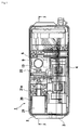
- an electric steering locking apparatus 1 includes a frame 2 and a cover 3 that covers an upper portion of the frame 2.
- a motor unit 4 which is a drive source is fixed on the frame 2 covered with the cover 3.
- the motor unit 4 includes a speed reduction mechanism therein, and a cam plate 5 which is a cam member is fixed to a rotation shaft (not shown) projecting from a unit case.
- the cam plate 5 is rotated in an unlocking direction R1 and its opposite locking direction R2 by rotation of the rotation shaft.
- the cam plate 5 includes a cam main body 5a and a substantially sector barycenter adjusting unit 5b which is integrally formed on the cam main body 5a using the same material.
- An outer peripheral surface of the cam main body 5a is formed as a sliding surface 6.
- the sliding surface 6 is set such that a distance from a rotation center O to the sliding surface 6 is gradually varied with variation of the rotation angle.
- the cam plate 5 is set such that the rotation center O coincides with a center of gravity G by the barycenter adjusting unit 5b.
- the frame 2 is formed with a sliding hole 7 penetrating the frame 2 in a vertical direction.
- a locking shaft 8 which is a locking member is movably disposed in the sliding hole 7.
- a hanger portion 9 is fixed to an upper end of the locking shaft 8.
- a lower surface of the hanger portion 9 is formed as a cam abutment surface 10.
- the cam abutment surface 10 abuts against the sliding surface 6 of the cam plate 5.
- Spring force of a spring 13 is applied to an upper surface of the hanger portion 9.
- the locking shaft 8 is biased toward the locking position by the spring force and the cam abutment surface 10 is pushed by the cam plate 5.
- the locking shaft 8 is provided at its lower end with an engaging pin portion 11.
- the locking shaft 8 moves by following the sliding surface 6 of the cam plate 5, and moves between a locking position shown in Figs. 5 to 7 and an unlocking position shown in Figs. 2 to 4.
- the engaging pin portion 11 enters between projections 12a of a steering shaft 12 (state shown in Fig. 6), thereby preventing rotation of the steering shaft 12.
- the engaging pin portion 11 is located out of rotation locus of the projections 12a of the steering shaft 12 (state shown in Fig. 3), thereby permitting the rotation of the steering shaft 12.
- the electric steering locking apparatus 1 includes a steering lock preventing unit 20.
- the steering lock preventing unit 20 includes an electromagnetic solenoid 21 fixed on the frame 2 covered with the cover 3.
- One end of a lock plate 22 is fixed to an extendable rod 21a of the electromagnetic solenoid 21.
- a tip end of the lock plate 22 extends to a position close to the locking shaft 8.
- the lock plate 22 enters a retaining groove 23 of the locking shaft 8 by a spring 24, thereby preventing the locking shaft 8 from moving. If the electromagnetic solenoid 21 is turned ON, the lock plate 22 retreats from the retaining groove 23 of the locking shaft 8, and the locking shaft 8 is permitted to move.
- the locking shaft 8 is located in the locking position shown in Figs. 5 to 7, and the rotation of the steering shaft 12 is locked.
- the vehicle can be theftproof.
- a driver depresses a steering lock switch (not shown) to start an engine
- the motor unit 4 is driven to rotate the cam plate 5 in the unlocking direction R1.
- the locking shaft 8 moves to the unlocking position shown in Figs. 2 to 4, and the rotation of the steering shaft 12 is permitted.
- the electromagnetic solenoid 21 of the steering lock preventing unit 20 is retained to the retaining groove 23 of the locking shaft 8 by the biasing force of the spring 24. While the engine is started and the vehicle runs, the locking shaft 8 keeps the unlocking position and the steering shaft 12 is permitted to freely rotate.
- the electromagnetic solenoid 21 of the steering lock preventing unit 20 is turned ON, the lock plate 22 is disengaged from the retaining groove 23 of the locking shaft 8, the motor unit 4 is driven, and the cam plate 5 is rotated in the locking direction R2. With this, the locking shaft 8 moves to the locking position shown in Figs. 5 to 7, and the steering shaft 12 is prevented from rotating.
- the locking shaft 8 when the locking shaft 8 is in the unlocking position, the locking shaft 8 is prevented from moving toward the locking position also by the steering lock preventing unit 20.
- a possibility that the steering shaft 12 is locked during running of the vehicle is prevented by the above-described configuration of the cam plate 5 and by the steering lock preventing unit 20.
- the cam plate 5 prevents the locking shaft 8 from locking the steering shaft 12.
- the steering lock preventing unit 20 prevents the locking shaft 8 biased by the spring 13 from locking the steering shaft 12, for example, when the motor unit 4 is erroneously operated and the cam plate 5 tries to rotate unintentionally or when the locking shaft 8 is unintentionally disengaged from the cam plate 5 by abrupt vibration or the like during running.
- the cam plate 5 is set so that the rotation center O coincides with the center of gravity G by integrally providing the cam main body 5a with the barycenter adjusting unit 5b which is made of the same material.
- the barycenter adjusting unit 5b which is made of the same material.
- the steering lock preventing unit 20 is provided in this embodiment, it is possible to prevent locking of the steering shaft 12 during running of the vehicle without providing the steering lock preventing unit 20. If the steering lock preventing unit 20 is not provided, the electric steering locking apparatus 1 can be reduced in size, weight, and cost.
Abstract
Description
- The present invention relates to an electric steering locking apparatus that locks a steering shaft of an automobile.
-
Japanese Patent Application Laid-Open No. 2002-205622 - With the above configuration, while a vehicle is parked, the locking member is located in the locking position and the steering shaft is locked. Thus, the vehicle can be theftproof during parking.
- When a parked vehicle is to be driven, the cam member rotates in the unlocking direction by the driving operation of the drive source, the locking member is brought into the unlocking position, and the rotation of the steering shaft is permitted.
- In the electric steering locking apparatus, it is necessary to always maintain the locking member in the unlocking position except during parking, and to maintain the locking member in the locking position during parking. If a relation between a rotation position and a center of gravity of the cam member is not taken into consideration, following problem occurs.
- That is, if the center of gravity of the cam member is deflected with respect to the rotation center of the cam member, self-inertia moment is generated by impact, vibration, or the like which is applied to the cam member. In a position of the cam member where the locking member is brought into the unlocking position, if the direction of the self-inertia moment matches with the locking direction of the cam member, there is a possibility that the cam member rotates in the locking direction and the locking member moves to the locking position. In a position of the cam member where the locking member is brought into the locking position, if the direction of the self-inertia moment matches with the unlocking direction of the cam member, there is a possibility that the cam member rotates in the unlocking direction and the locking member moves to the unlocking position.
- It is an object of the present invention to provide an electric steering locking apparatus that can prevent the cam member from moving by the self-inertia moment.
- To achieve the above object, according to an aspect of the present invention, there is provided an electric steering locking apparatus including a cam member that rotates in an unlocking direction and a locking direction by driving operation of a drive source, and a locking member that follows a sliding surface of the cam member and that moves between a locking position where the rotation of a steering shaft is prevented and an unlocking position where the rotation of the steering shaft is permitted, wherein the cam member is set such that a rotation center coincides with a center of gravity.
- With this configuration, even when impact, vibration, or the like is applied to the cam member, no self-inertia moment is generated in the cam member. Thus, displacement caused by the self-inertia moment can be prevented.
- The electric steering locking apparatus may further include a steering lock preventing unit that prevents the locking member located in the unlocking position from moving.
- With this configuration, since the locking member is prevented from moving toward the locking position also by the steering lock preventing unit, the unlocking position of the locking member can be maintained more reliably.
-
- Fig. 1 is a plan view of an electric steering locking apparatus according to an embodiment of the present invention.
- Fig. 2 is a cross section taken along line 2-2 in Fig. 1 when a locking shaft is in an unlocking position according to the embodiment of the invention.
- Fig. 3 is a cross section taken along line 3-3 in Fig. 2 according to the embodiment of the invention.
- Fig. 4 is a schematic enlarged view showing a layout of the locking shaft and a cam plate in an unlocking position according to the embodiment of the invention.
- Fig. 5 is a cross section taken along line 2-2 in Fig. 1 when the locking shaft is in a locking position according to the embodiment of the invention.
- Fig. 6 is a cross section taken along line 6-6 in Fig. 5 according to the embodiment of the invention.
- Fig. 7 is schematic enlarged view showing a layout of the locking shaft and the cam plate in the locking position according to the embodiment of the invention.
- Fig. 8(a) is a perspective view of the cam plate as viewed from a cam main body side and Fig. 8(b) is a perspective view of the cam plate as viewed from a barycenter adjusting unit side, respectively according to the embodiment of the invention.
- An embodiment of the present invention will be explained below with reference to the drawings.
- As shown in Figs. 1, 2, and 5, an electric
steering locking apparatus 1 includes aframe 2 and acover 3 that covers an upper portion of theframe 2. A motor unit 4 which is a drive source is fixed on theframe 2 covered with thecover 3. The motor unit 4 includes a speed reduction mechanism therein, and acam plate 5 which is a cam member is fixed to a rotation shaft (not shown) projecting from a unit case. - The
cam plate 5 is rotated in an unlocking direction R1 and its opposite locking direction R2 by rotation of the rotation shaft. As shown in Figs. 8(a) and (b) in detail, thecam plate 5 includes a cammain body 5a and a substantially sectorbarycenter adjusting unit 5b which is integrally formed on the cammain body 5a using the same material. An outer peripheral surface of the cammain body 5a is formed as a slidingsurface 6. The slidingsurface 6 is set such that a distance from a rotation center O to the slidingsurface 6 is gradually varied with variation of the rotation angle. Thecam plate 5 is set such that the rotation center O coincides with a center of gravity G by thebarycenter adjusting unit 5b. - With reference to Figs. 2 and 5, the
frame 2 is formed with asliding hole 7 penetrating theframe 2 in a vertical direction. Alocking shaft 8 which is a locking member is movably disposed in thesliding hole 7. Ahanger portion 9 is fixed to an upper end of thelocking shaft 8. A lower surface of thehanger portion 9 is formed as acam abutment surface 10. The cam abutment surface 10 abuts against the slidingsurface 6 of thecam plate 5. Spring force of aspring 13 is applied to an upper surface of thehanger portion 9. Thelocking shaft 8 is biased toward the locking position by the spring force and thecam abutment surface 10 is pushed by thecam plate 5. - The
locking shaft 8 is provided at its lower end with anengaging pin portion 11. Thelocking shaft 8 moves by following the slidingsurface 6 of thecam plate 5, and moves between a locking position shown in Figs. 5 to 7 and an unlocking position shown in Figs. 2 to 4. In the locking position, theengaging pin portion 11 enters betweenprojections 12a of a steering shaft 12 (state shown in Fig. 6), thereby preventing rotation of thesteering shaft 12. In the unlocking position, theengaging pin portion 11 is located out of rotation locus of theprojections 12a of the steering shaft 12 (state shown in Fig. 3), thereby permitting the rotation of thesteering shaft 12. - As shown in Figs. 1, 2, and 5, the electric
steering locking apparatus 1 includes a steeringlock preventing unit 20. The steeringlock preventing unit 20 includes anelectromagnetic solenoid 21 fixed on theframe 2 covered with thecover 3. One end of alock plate 22 is fixed to anextendable rod 21a of theelectromagnetic solenoid 21. A tip end of thelock plate 22 extends to a position close to thelocking shaft 8. When thelocking shaft 8 is located in the unlocking position and theelectromagnetic solenoid 21 is turned OFF, thelock plate 22 enters aretaining groove 23 of thelocking shaft 8 by aspring 24, thereby preventing thelocking shaft 8 from moving. If theelectromagnetic solenoid 21 is turned ON, thelock plate 22 retreats from theretaining groove 23 of thelocking shaft 8, and thelocking shaft 8 is permitted to move. - With this configuration, while the vehicle is parked, the
locking shaft 8 is located in the locking position shown in Figs. 5 to 7, and the rotation of thesteering shaft 12 is locked. Thus, the vehicle can be theftproof. - If a driver depresses a steering lock switch (not shown) to start an engine, the motor unit 4 is driven to rotate the
cam plate 5 in the unlocking direction R1. With this, thelocking shaft 8 moves to the unlocking position shown in Figs. 2 to 4, and the rotation of thesteering shaft 12 is permitted. - If the
locking shaft 8 moves to the unlocking position, theelectromagnetic solenoid 21 of the steeringlock preventing unit 20 is retained to theretaining groove 23 of thelocking shaft 8 by the biasing force of thespring 24. While the engine is started and the vehicle runs, thelocking shaft 8 keeps the unlocking position and thesteering shaft 12 is permitted to freely rotate. - If the engine is stopped and the
locking shaft 8 moves to the locking position, theelectromagnetic solenoid 21 of the steeringlock preventing unit 20 is turned ON, thelock plate 22 is disengaged from theretaining groove 23 of thelocking shaft 8, the motor unit 4 is driven, and thecam plate 5 is rotated in the locking direction R2. With this, thelocking shaft 8 moves to the locking position shown in Figs. 5 to 7, and thesteering shaft 12 is prevented from rotating. - In the electric
steering locking apparatus 1 operated as described above, even when an external force such as impact and vibration is applied to thecam plate 5, since the rotation center O coincides with the center of gravity G, self-inertia moment which may occur due to the impact, vibration, or the like is not generated in thecam plate 5. Therefore, in the position (Figs. 2 to 4) of thecam plate 5 where the lockingshaft 8 is in the unlocking position, thecam plate 5 will not be rotated in the locking direction by the self-inertia moment to move the lockingshaft 8 to the locking position. In the position (Figs. 5 to 7) of thecam plate 5 where the lockingshaft 8 is in the locking position, thecam plate 5 will not be rotated in the unlocking direction by the self-inertia moment to move the lockingshaft 8 to the unlocking position. - In the embodiment, when the locking
shaft 8 is in the unlocking position, the lockingshaft 8 is prevented from moving toward the locking position also by the steeringlock preventing unit 20. - In the embodiment, a possibility that the steering
shaft 12 is locked during running of the vehicle is prevented by the above-described configuration of thecam plate 5 and by the steeringlock preventing unit 20. Particularly, when the steeringlock preventing unit 20 does not normally operate for some reason, thecam plate 5 prevents the lockingshaft 8 from locking the steeringshaft 12. The steeringlock preventing unit 20 prevents the lockingshaft 8 biased by thespring 13 from locking the steeringshaft 12, for example, when the motor unit 4 is erroneously operated and thecam plate 5 tries to rotate unintentionally or when the lockingshaft 8 is unintentionally disengaged from thecam plate 5 by abrupt vibration or the like during running. - In this embodiment, the
cam plate 5 is set so that the rotation center O coincides with the center of gravity G by integrally providing the cammain body 5a with thebarycenter adjusting unit 5b which is made of the same material. Alternatively, it is also possible to form a hollow portion or the like in thecam plate 5 itself by making thebarycenter adjusting unit 5b of a different material, and to match the rotation center O and the center of gravity G with each other without providing thebarycenter adjusting unit 5b. - Although the steering
lock preventing unit 20 is provided in this embodiment, it is possible to prevent locking of the steeringshaft 12 during running of the vehicle without providing the steeringlock preventing unit 20. If the steeringlock preventing unit 20 is not provided, the electricsteering locking apparatus 1 can be reduced in size, weight, and cost.
Claims (2)
- An electric steering locking apparatus comprising:a cam member that rotates in an unlocking direction and a locking direction by driving operation of a drive source; anda locking member that moves between a locking position where a steering shaft is prevented from rotating and an unlocking position where the steering shaft is permitted to rotate by rotation of the cam member,wherein the cam member is set such that a rotation center coincides with a center of gravity.
- The electric steering locking apparatus according to claim 1, further comprising a steering lock preventing unit that prevents the locking member located in the unlocking position from moving.
Applications Claiming Priority (2)
| Application Number | Priority Date | Filing Date | Title |
|---|---|---|---|
| JP2004315834A JP3819925B2 (en) | 2004-10-29 | 2004-10-29 | Electric steering lock device |
| PCT/JP2005/017254 WO2006046365A1 (en) | 2004-10-29 | 2005-09-20 | Electric steering lock device |
Publications (3)
| Publication Number | Publication Date |
|---|---|
| EP1783015A1 true EP1783015A1 (en) | 2007-05-09 |
| EP1783015A4 EP1783015A4 (en) | 2009-11-04 |
| EP1783015B1 EP1783015B1 (en) | 2013-04-24 |
Family
ID=36227615
Family Applications (1)
| Application Number | Title | Priority Date | Filing Date |
|---|---|---|---|
| EP20050785347 Active EP1783015B1 (en) | 2004-10-29 | 2005-09-20 | Electric steering locking apparatus |
Country Status (5)
| Country | Link |
|---|---|
| US (1) | US7810363B2 (en) |
| EP (1) | EP1783015B1 (en) |
| JP (1) | JP3819925B2 (en) |
| CN (1) | CN100422003C (en) |
| WO (1) | WO2006046365A1 (en) |
Families Citing this family (17)
| Publication number | Priority date | Publication date | Assignee | Title |
|---|---|---|---|---|
| JP2008018814A (en) * | 2006-07-12 | 2008-01-31 | Tokai Rika Co Ltd | Steering lock device |
| JP4980853B2 (en) * | 2006-11-10 | 2012-07-18 | 株式会社アルファ | Electric steering lock device |
| US7891221B2 (en) * | 2007-10-01 | 2011-02-22 | Alpha Corporation | Electric steering lock device |
| US7596976B2 (en) * | 2007-11-30 | 2009-10-06 | Alpha Corporation | Electric steering lock device |
| WO2009147919A1 (en) * | 2008-06-06 | 2009-12-10 | 本田技研工業株式会社 | Steering lock device |
| CN101824941B (en) * | 2009-03-06 | 2014-07-09 | 株式会社有信 | Electric steering locking apparatus |
| US8424348B2 (en) * | 2010-01-27 | 2013-04-23 | Strattec Security Corporation | Steering lock |
| PL2479073T3 (en) * | 2011-01-21 | 2014-06-30 | Valeo Sicherheitssysteme Gmbh | Steering-wheel antitheft device for an automobile |
| JP5805979B2 (en) * | 2011-04-13 | 2015-11-10 | 株式会社アルファ | Locking device |
| JP5287958B2 (en) * | 2011-09-22 | 2013-09-11 | 沖電気工業株式会社 | Lock device and storage device |
| DE102013217735A1 (en) | 2012-09-07 | 2014-03-13 | Strattec Security Corporation | steering lock |
| US8966948B2 (en) * | 2012-12-03 | 2015-03-03 | Hyundai Motor Company | Electrical steering column lock |
| WO2015049951A1 (en) * | 2013-10-04 | 2015-04-09 | 株式会社 アルファ | Electric steering lock |
| EP2965970B1 (en) * | 2014-04-11 | 2017-03-29 | NSK Ltd. | Steering device |
| JP6471105B2 (en) * | 2016-01-14 | 2019-02-13 | 株式会社東海理化電機製作所 | Steering lock device and method of assembling steering locking device |
| EP3339110B1 (en) * | 2016-12-22 | 2020-02-05 | Asahi Denso Co., Ltd. | Engine starting device |
| JP6851044B2 (en) * | 2016-12-22 | 2021-03-31 | 朝日電装株式会社 | Engine starter |
Citations (3)
| Publication number | Priority date | Publication date | Assignee | Title |
|---|---|---|---|---|
| US20020088257A1 (en) * | 2001-01-09 | 2002-07-11 | Dimig Steven J. | Steering column lock apparatus and method |
| US20020108412A1 (en) * | 2001-01-24 | 2002-08-15 | Valeo Sicherheitssysteme Gmbh | Locking device |
| JP2003276565A (en) * | 2002-03-22 | 2003-10-02 | Tokai Rika Co Ltd | Electric steering lock device |
Family Cites Families (25)
| Publication number | Priority date | Publication date | Assignee | Title |
|---|---|---|---|---|
| JPS60250184A (en) * | 1984-05-26 | 1985-12-10 | 株式会社 ニフコ | Control of opening speed of car receiving box in car room |
| JPH0563992A (en) | 1991-09-05 | 1993-03-12 | Fujitsu Ltd | Image data encoder and image data restoring device |
| JP2557056Y2 (en) * | 1992-02-03 | 1997-12-08 | 株式会社パイオラックス | Car storage device with safety function |
| JPH06158924A (en) * | 1992-11-25 | 1994-06-07 | Tokai Rika Co Ltd | Steering lock device |
| EP0610882B1 (en) * | 1993-02-12 | 1996-11-20 | Kato Hatsujo Kaisha Ltd. | Storage device with safety function |
| CN2160717Y (en) * | 1993-04-26 | 1994-04-06 | 丁樟富 | Anti-theft warehouse lock without key |
| DE69832114T2 (en) * | 1997-03-28 | 2006-07-27 | Honda Lock Mfg. Co., Ltd. | Device for locking the steering |
| JPH1194691A (en) * | 1997-09-24 | 1999-04-09 | Sekisui Chem Co Ltd | Exciter |
| JP3394909B2 (en) * | 1998-05-27 | 2003-04-07 | 旭サナック株式会社 | Forging machine |
| JP3592941B2 (en) * | 1998-11-24 | 2004-11-24 | 株式会社東海理化電機製作所 | Steering lock device |
| FR2788477B1 (en) * | 1999-01-15 | 2001-02-16 | Valeo Securite Habitacle | MOTOR VEHICLE STEERING LOCK |
| FR2799426B1 (en) * | 1999-09-17 | 2001-12-07 | Valeo Securite Habitacle | MOTOR VEHICLE STEERING LOCK |
| FR2807373B1 (en) * | 2000-04-10 | 2002-06-21 | Valeo Securite Habitacle | MOTOR VEHICLE ANTITHEFT COMPRISING IMPROVED PEN RETAINING MEANS |
| DE10018727A1 (en) * | 2000-04-15 | 2001-10-18 | Bayerische Motoren Werke Ag | Remote-controlled ignition steering lock for motorcycles |
| JP3749126B2 (en) | 2001-01-11 | 2006-02-22 | 株式会社ユーシン | Electric steering lock device |
| JP3851803B2 (en) * | 2001-02-09 | 2006-11-29 | 株式会社東海理化電機製作所 | Electronic vehicle anti-theft device |
| JP2002234419A (en) * | 2001-02-09 | 2002-08-20 | Tokai Rika Co Ltd | Electronic steering lock mechanism |
| JP2002308049A (en) * | 2001-04-11 | 2002-10-23 | Tokai Rika Co Ltd | Engine starting device for vehicle |
| DE10121714C1 (en) * | 2001-05-04 | 2003-01-02 | Huf Huelsbeck & Fuerst Gmbh | Lock, in particular for locking the steering spindle of a motor vehicle |
| JP2003341479A (en) * | 2002-05-30 | 2003-12-03 | Tokai Rika Co Ltd | Electronic type car theft preventive device |
| DE10247802B3 (en) * | 2002-10-14 | 2004-02-05 | Huf Hülsbeck & Fürst Gmbh & Co. Kg | Automobile steering spindle locking device has security element pin spring-biased into engagement with recess of blocking bolt for preventing unauthorized release of latter |
| US7140213B2 (en) * | 2004-02-21 | 2006-11-28 | Strattec Security Corporation | Steering column lock apparatus and method |
| JP4435641B2 (en) * | 2004-07-29 | 2010-03-24 | 株式会社東海理化電機製作所 | Steering lock device |
| JP4358060B2 (en) * | 2004-07-30 | 2009-11-04 | 株式会社ホンダロック | Inspection device for steering lock device |
| KR100622495B1 (en) * | 2004-10-01 | 2006-09-19 | 현대자동차주식회사 | steering column lock for a personal id-card system |
-
2004
- 2004-10-29 JP JP2004315834A patent/JP3819925B2/en active Active
-
2005
- 2005-09-20 US US11/579,634 patent/US7810363B2/en not_active Expired - Fee Related
- 2005-09-20 WO PCT/JP2005/017254 patent/WO2006046365A1/en active Application Filing
- 2005-09-20 CN CNB2005800114938A patent/CN100422003C/en active Active
- 2005-09-20 EP EP20050785347 patent/EP1783015B1/en active Active
Patent Citations (3)
| Publication number | Priority date | Publication date | Assignee | Title |
|---|---|---|---|---|
| US20020088257A1 (en) * | 2001-01-09 | 2002-07-11 | Dimig Steven J. | Steering column lock apparatus and method |
| US20020108412A1 (en) * | 2001-01-24 | 2002-08-15 | Valeo Sicherheitssysteme Gmbh | Locking device |
| JP2003276565A (en) * | 2002-03-22 | 2003-10-02 | Tokai Rika Co Ltd | Electric steering lock device |
Non-Patent Citations (1)
| Title |
|---|
| See also references of WO2006046365A1 * |
Also Published As
| Publication number | Publication date |
|---|---|
| EP1783015B1 (en) | 2013-04-24 |
| EP1783015A4 (en) | 2009-11-04 |
| JP2006123782A (en) | 2006-05-18 |
| US20080271504A1 (en) | 2008-11-06 |
| CN100422003C (en) | 2008-10-01 |
| WO2006046365A1 (en) | 2006-05-04 |
| CN1942348A (en) | 2007-04-04 |
| US7810363B2 (en) | 2010-10-12 |
| JP3819925B2 (en) | 2006-09-13 |
Similar Documents
| Publication | Publication Date | Title |
|---|---|---|
| EP1783015A1 (en) | Electric steering lock device | |
| EP1783016B1 (en) | Electric steering lock device | |
| JP5147217B2 (en) | Steering lock device | |
| KR100686997B1 (en) | Electric steering lock apparatus | |
| US7055351B2 (en) | Electrically-driven steering lock device | |
| KR101506365B1 (en) | Steering lock device | |
| EP2065266B1 (en) | Electric steering lock device | |
| EP2045150A1 (en) | Electric steering lock device | |
| JP2004231123A (en) | Electric steering lock device | |
| JP4348245B2 (en) | Steering lock device | |
| JP4863839B2 (en) | Electric steering lock device | |
| KR100808748B1 (en) | Electric steering lock device | |
| JP3657137B2 (en) | Engine starter | |
| KR100764357B1 (en) | Electric steering lock device | |
| JP3174007B2 (en) | Steering lock device | |
| JP4587864B2 (en) | Electric steering lock device | |
| KR100410761B1 (en) | ignition lock switch of vehicle |
Legal Events
| Date | Code | Title | Description |
|---|---|---|---|
| PUAI | Public reference made under article 153(3) epc to a published international application that has entered the european phase |
Free format text: ORIGINAL CODE: 0009012 |
|
| 17P | Request for examination filed |
Effective date: 20061206 |
|
| AK | Designated contracting states |
Kind code of ref document: A1 Designated state(s): AT BE BG CH CY CZ DE DK EE ES FI FR GB GR HU IE IS IT LI LT LU LV MC NL PL PT RO SE SI SK TR |
|
| RIN1 | Information on inventor provided before grant (corrected) |
Inventor name: OKADA, TAKAHIRO C/O ALPHA CORPORATION Inventor name: TSUKANO, TETSUYUKI C/O ALPHA CORPORATION |
|
| DAX | Request for extension of the european patent (deleted) | ||
| A4 | Supplementary search report drawn up and despatched |
Effective date: 20091007 |
|
| 17Q | First examination report despatched |
Effective date: 20100203 |
|
| GRAP | Despatch of communication of intention to grant a patent |
Free format text: ORIGINAL CODE: EPIDOSNIGR1 |
|
| GRAS | Grant fee paid |
Free format text: ORIGINAL CODE: EPIDOSNIGR3 |
|
| GRAA | (expected) grant |
Free format text: ORIGINAL CODE: 0009210 |
|
| AK | Designated contracting states |
Kind code of ref document: B1 Designated state(s): AT BE BG CH CY CZ DE DK EE ES FI FR GB GR HU IE IS IT LI LT LU LV MC NL PL PT RO SE SI SK TR |
|
| REG | Reference to a national code |
Ref country code: GB Ref legal event code: FG4D |
|
| REG | Reference to a national code |
Ref country code: CH Ref legal event code: EP |
|
| REG | Reference to a national code |
Ref country code: AT Ref legal event code: REF Ref document number: 608428 Country of ref document: AT Kind code of ref document: T Effective date: 20130515 |
|
| REG | Reference to a national code |
Ref country code: IE Ref legal event code: FG4D |
|
| REG | Reference to a national code |
Ref country code: DE Ref legal event code: R096 Ref document number: 602005039277 Country of ref document: DE Effective date: 20130620 |
|
| REG | Reference to a national code |
Ref country code: AT Ref legal event code: MK05 Ref document number: 608428 Country of ref document: AT Kind code of ref document: T Effective date: 20130424 |
|
| REG | Reference to a national code |
Ref country code: LT Ref legal event code: MG4D |
|
| REG | Reference to a national code |
Ref country code: NL Ref legal event code: VDEP Effective date: 20130424 |
|
| PG25 | Lapsed in a contracting state [announced via postgrant information from national office to epo] |
Ref country code: SE Free format text: LAPSE BECAUSE OF FAILURE TO SUBMIT A TRANSLATION OF THE DESCRIPTION OR TO PAY THE FEE WITHIN THE PRESCRIBED TIME-LIMIT Effective date: 20130424 Ref country code: AT Free format text: LAPSE BECAUSE OF FAILURE TO SUBMIT A TRANSLATION OF THE DESCRIPTION OR TO PAY THE FEE WITHIN THE PRESCRIBED TIME-LIMIT Effective date: 20130424 Ref country code: PT Free format text: LAPSE BECAUSE OF FAILURE TO SUBMIT A TRANSLATION OF THE DESCRIPTION OR TO PAY THE FEE WITHIN THE PRESCRIBED TIME-LIMIT Effective date: 20130826 Ref country code: ES Free format text: LAPSE BECAUSE OF FAILURE TO SUBMIT A TRANSLATION OF THE DESCRIPTION OR TO PAY THE FEE WITHIN THE PRESCRIBED TIME-LIMIT Effective date: 20130804 Ref country code: FI Free format text: LAPSE BECAUSE OF FAILURE TO SUBMIT A TRANSLATION OF THE DESCRIPTION OR TO PAY THE FEE WITHIN THE PRESCRIBED TIME-LIMIT Effective date: 20130424 Ref country code: LT Free format text: LAPSE BECAUSE OF FAILURE TO SUBMIT A TRANSLATION OF THE DESCRIPTION OR TO PAY THE FEE WITHIN THE PRESCRIBED TIME-LIMIT Effective date: 20130424 Ref country code: BE Free format text: LAPSE BECAUSE OF FAILURE TO SUBMIT A TRANSLATION OF THE DESCRIPTION OR TO PAY THE FEE WITHIN THE PRESCRIBED TIME-LIMIT Effective date: 20130424 Ref country code: SI Free format text: LAPSE BECAUSE OF FAILURE TO SUBMIT A TRANSLATION OF THE DESCRIPTION OR TO PAY THE FEE WITHIN THE PRESCRIBED TIME-LIMIT Effective date: 20130424 Ref country code: GR Free format text: LAPSE BECAUSE OF FAILURE TO SUBMIT A TRANSLATION OF THE DESCRIPTION OR TO PAY THE FEE WITHIN THE PRESCRIBED TIME-LIMIT Effective date: 20130725 Ref country code: IS Free format text: LAPSE BECAUSE OF FAILURE TO SUBMIT A TRANSLATION OF THE DESCRIPTION OR TO PAY THE FEE WITHIN THE PRESCRIBED TIME-LIMIT Effective date: 20130824 |
|
| PG25 | Lapsed in a contracting state [announced via postgrant information from national office to epo] |
Ref country code: LV Free format text: LAPSE BECAUSE OF FAILURE TO SUBMIT A TRANSLATION OF THE DESCRIPTION OR TO PAY THE FEE WITHIN THE PRESCRIBED TIME-LIMIT Effective date: 20130424 Ref country code: PL Free format text: LAPSE BECAUSE OF FAILURE TO SUBMIT A TRANSLATION OF THE DESCRIPTION OR TO PAY THE FEE WITHIN THE PRESCRIBED TIME-LIMIT Effective date: 20130424 Ref country code: BG Free format text: LAPSE BECAUSE OF FAILURE TO SUBMIT A TRANSLATION OF THE DESCRIPTION OR TO PAY THE FEE WITHIN THE PRESCRIBED TIME-LIMIT Effective date: 20130724 Ref country code: CY Free format text: LAPSE BECAUSE OF FAILURE TO SUBMIT A TRANSLATION OF THE DESCRIPTION OR TO PAY THE FEE WITHIN THE PRESCRIBED TIME-LIMIT Effective date: 20130424 |
|
| PG25 | Lapsed in a contracting state [announced via postgrant information from national office to epo] |
Ref country code: CZ Free format text: LAPSE BECAUSE OF FAILURE TO SUBMIT A TRANSLATION OF THE DESCRIPTION OR TO PAY THE FEE WITHIN THE PRESCRIBED TIME-LIMIT Effective date: 20130424 Ref country code: DK Free format text: LAPSE BECAUSE OF FAILURE TO SUBMIT A TRANSLATION OF THE DESCRIPTION OR TO PAY THE FEE WITHIN THE PRESCRIBED TIME-LIMIT Effective date: 20130424 Ref country code: SK Free format text: LAPSE BECAUSE OF FAILURE TO SUBMIT A TRANSLATION OF THE DESCRIPTION OR TO PAY THE FEE WITHIN THE PRESCRIBED TIME-LIMIT Effective date: 20130424 Ref country code: EE Free format text: LAPSE BECAUSE OF FAILURE TO SUBMIT A TRANSLATION OF THE DESCRIPTION OR TO PAY THE FEE WITHIN THE PRESCRIBED TIME-LIMIT Effective date: 20130424 |
|
| PG25 | Lapsed in a contracting state [announced via postgrant information from national office to epo] |
Ref country code: RO Free format text: LAPSE BECAUSE OF FAILURE TO SUBMIT A TRANSLATION OF THE DESCRIPTION OR TO PAY THE FEE WITHIN THE PRESCRIBED TIME-LIMIT Effective date: 20130424 Ref country code: NL Free format text: LAPSE BECAUSE OF FAILURE TO SUBMIT A TRANSLATION OF THE DESCRIPTION OR TO PAY THE FEE WITHIN THE PRESCRIBED TIME-LIMIT Effective date: 20130424 Ref country code: IT Free format text: LAPSE BECAUSE OF FAILURE TO SUBMIT A TRANSLATION OF THE DESCRIPTION OR TO PAY THE FEE WITHIN THE PRESCRIBED TIME-LIMIT Effective date: 20130424 |
|
| PLBE | No opposition filed within time limit |
Free format text: ORIGINAL CODE: 0009261 |
|
| STAA | Information on the status of an ep patent application or granted ep patent |
Free format text: STATUS: NO OPPOSITION FILED WITHIN TIME LIMIT |
|
| 26N | No opposition filed |
Effective date: 20140127 |
|
| PG25 | Lapsed in a contracting state [announced via postgrant information from national office to epo] |
Ref country code: MC Free format text: LAPSE BECAUSE OF FAILURE TO SUBMIT A TRANSLATION OF THE DESCRIPTION OR TO PAY THE FEE WITHIN THE PRESCRIBED TIME-LIMIT Effective date: 20130424 |
|
| REG | Reference to a national code |
Ref country code: CH Ref legal event code: PL |
|
| REG | Reference to a national code |
Ref country code: DE Ref legal event code: R097 Ref document number: 602005039277 Country of ref document: DE Effective date: 20140127 |
|
| REG | Reference to a national code |
Ref country code: IE Ref legal event code: MM4A |
|
| PG25 | Lapsed in a contracting state [announced via postgrant information from national office to epo] |
Ref country code: CH Free format text: LAPSE BECAUSE OF NON-PAYMENT OF DUE FEES Effective date: 20130930 Ref country code: IE Free format text: LAPSE BECAUSE OF NON-PAYMENT OF DUE FEES Effective date: 20130920 Ref country code: LI Free format text: LAPSE BECAUSE OF NON-PAYMENT OF DUE FEES Effective date: 20130930 |
|
| PG25 | Lapsed in a contracting state [announced via postgrant information from national office to epo] |
Ref country code: TR Free format text: LAPSE BECAUSE OF FAILURE TO SUBMIT A TRANSLATION OF THE DESCRIPTION OR TO PAY THE FEE WITHIN THE PRESCRIBED TIME-LIMIT Effective date: 20130424 |
|
| PG25 | Lapsed in a contracting state [announced via postgrant information from national office to epo] |
Ref country code: LU Free format text: LAPSE BECAUSE OF NON-PAYMENT OF DUE FEES Effective date: 20130920 Ref country code: HU Free format text: LAPSE BECAUSE OF FAILURE TO SUBMIT A TRANSLATION OF THE DESCRIPTION OR TO PAY THE FEE WITHIN THE PRESCRIBED TIME-LIMIT; INVALID AB INITIO Effective date: 20050920 |
|
| REG | Reference to a national code |
Ref country code: FR Ref legal event code: PLFP Year of fee payment: 12 |
|
| REG | Reference to a national code |
Ref country code: FR Ref legal event code: PLFP Year of fee payment: 13 |
|
| PGFP | Annual fee paid to national office [announced via postgrant information from national office to epo] |
Ref country code: GB Payment date: 20170510 Year of fee payment: 10 |
|
| REG | Reference to a national code |
Ref country code: FR Ref legal event code: PLFP Year of fee payment: 14 |
|
| GBPC | Gb: european patent ceased through non-payment of renewal fee |
Effective date: 20180920 |
|
| PG25 | Lapsed in a contracting state [announced via postgrant information from national office to epo] |
Ref country code: GB Free format text: LAPSE BECAUSE OF NON-PAYMENT OF DUE FEES Effective date: 20180920 |
|
| PGFP | Annual fee paid to national office [announced via postgrant information from national office to epo] |
Ref country code: FR Payment date: 20200925 Year of fee payment: 16 |
|
| PG25 | Lapsed in a contracting state [announced via postgrant information from national office to epo] |
Ref country code: FR Free format text: LAPSE BECAUSE OF NON-PAYMENT OF DUE FEES Effective date: 20210930 |
|
| PGFP | Annual fee paid to national office [announced via postgrant information from national office to epo] |
Ref country code: DE Payment date: 20230926 Year of fee payment: 19 |