EP1783064B1 - Plastic pouch and method of producing the same - Google Patents
Plastic pouch and method of producing the same Download PDFInfo
- Publication number
- EP1783064B1 EP1783064B1 EP05776978.8A EP05776978A EP1783064B1 EP 1783064 B1 EP1783064 B1 EP 1783064B1 EP 05776978 A EP05776978 A EP 05776978A EP 1783064 B1 EP1783064 B1 EP 1783064B1
- Authority
- EP
- European Patent Office
- Prior art keywords
- pouch
- folded
- plastic pouch
- surface member
- plastic
- Prior art date
- Legal status (The legal status is an assumption and is not a legal conclusion. Google has not performed a legal analysis and makes no representation as to the accuracy of the status listed.)
- Active
Links
- 229920003023 plastic Polymers 0.000 title claims description 226
- 239000004033 plastic Substances 0.000 title claims description 226
- 238000000034 method Methods 0.000 title claims description 57
- 238000004519 manufacturing process Methods 0.000 claims description 160
- 238000007789 sealing Methods 0.000 claims description 70
- 230000007246 mechanism Effects 0.000 claims description 34
- 230000002093 peripheral effect Effects 0.000 claims description 30
- 230000015572 biosynthetic process Effects 0.000 claims description 24
- 230000004044 response Effects 0.000 claims description 11
- 238000004891 communication Methods 0.000 claims description 4
- XEEYBQQBJWHFJM-UHFFFAOYSA-N Iron Chemical compound [Fe] XEEYBQQBJWHFJM-UHFFFAOYSA-N 0.000 description 26
- 229920005989 resin Polymers 0.000 description 23
- 239000011347 resin Substances 0.000 description 23
- 229920005992 thermoplastic resin Polymers 0.000 description 21
- 238000012856 packing Methods 0.000 description 20
- QVGXLLKOCUKJST-UHFFFAOYSA-N atomic oxygen Chemical compound [O] QVGXLLKOCUKJST-UHFFFAOYSA-N 0.000 description 17
- 239000001301 oxygen Substances 0.000 description 17
- 229910052760 oxygen Inorganic materials 0.000 description 17
- 238000010411 cooking Methods 0.000 description 16
- 239000000853 adhesive Substances 0.000 description 15
- 230000001070 adhesive effect Effects 0.000 description 15
- 230000002745 absorbent Effects 0.000 description 14
- 239000002250 absorbent Substances 0.000 description 14
- 229910052742 iron Inorganic materials 0.000 description 13
- -1 polypropylene, propylene-ethylene copolymer Polymers 0.000 description 13
- 238000010438 heat treatment Methods 0.000 description 11
- 239000000463 material Substances 0.000 description 11
- 239000002651 laminated plastic film Substances 0.000 description 10
- 238000004806 packaging method and process Methods 0.000 description 10
- 239000004743 Polypropylene Substances 0.000 description 7
- 235000013305 food Nutrition 0.000 description 7
- 229920006284 nylon film Polymers 0.000 description 7
- 229920001155 polypropylene Polymers 0.000 description 7
- 230000004888 barrier function Effects 0.000 description 6
- 229920006267 polyester film Polymers 0.000 description 5
- 230000003244 pro-oxidative effect Effects 0.000 description 5
- FAPWRFPIFSIZLT-UHFFFAOYSA-M Sodium chloride Chemical compound [Na+].[Cl-] FAPWRFPIFSIZLT-UHFFFAOYSA-M 0.000 description 4
- 239000005038 ethylene vinyl acetate Substances 0.000 description 4
- 229920001200 poly(ethylene-vinyl acetate) Polymers 0.000 description 4
- OKTJSMMVPCPJKN-UHFFFAOYSA-N Carbon Chemical compound [C] OKTJSMMVPCPJKN-UHFFFAOYSA-N 0.000 description 3
- 238000005520 cutting process Methods 0.000 description 3
- 239000002985 plastic film Substances 0.000 description 3
- 229920006255 plastic film Polymers 0.000 description 3
- 239000010695 polyglycol Substances 0.000 description 3
- 229920000151 polyglycol Polymers 0.000 description 3
- 230000008569 process Effects 0.000 description 3
- 239000011342 resin composition Substances 0.000 description 3
- 239000000126 substance Substances 0.000 description 3
- 238000009966 trimming Methods 0.000 description 3
- 238000003466 welding Methods 0.000 description 3
- CIWBSHSKHKDKBQ-JLAZNSOCSA-N Ascorbic acid Chemical compound OC[C@H](O)[C@H]1OC(=O)C(O)=C1O CIWBSHSKHKDKBQ-JLAZNSOCSA-N 0.000 description 2
- UXVMQQNJUSDDNG-UHFFFAOYSA-L Calcium chloride Chemical compound [Cl-].[Cl-].[Ca+2] UXVMQQNJUSDDNG-UHFFFAOYSA-L 0.000 description 2
- CIWBSHSKHKDKBQ-DUZGATOHSA-N D-araboascorbic acid Natural products OC[C@@H](O)[C@H]1OC(=O)C(O)=C1O CIWBSHSKHKDKBQ-DUZGATOHSA-N 0.000 description 2
- 239000004831 Hot glue Substances 0.000 description 2
- 239000004677 Nylon Substances 0.000 description 2
- 229920002292 Nylon 6 Polymers 0.000 description 2
- 239000004372 Polyvinyl alcohol Substances 0.000 description 2
- VYPSYNLAJGMNEJ-UHFFFAOYSA-N Silicium dioxide Chemical compound O=[Si]=O VYPSYNLAJGMNEJ-UHFFFAOYSA-N 0.000 description 2
- PNEYBMLMFCGWSK-UHFFFAOYSA-N aluminium oxide Inorganic materials [O-2].[O-2].[O-2].[Al+3].[Al+3] PNEYBMLMFCGWSK-UHFFFAOYSA-N 0.000 description 2
- 239000002585 base Substances 0.000 description 2
- 239000001110 calcium chloride Substances 0.000 description 2
- 229910001628 calcium chloride Inorganic materials 0.000 description 2
- 229910052799 carbon Inorganic materials 0.000 description 2
- 150000001732 carboxylic acid derivatives Chemical class 0.000 description 2
- 239000011248 coating agent Substances 0.000 description 2
- 238000000576 coating method Methods 0.000 description 2
- 150000001875 compounds Chemical class 0.000 description 2
- 229920001577 copolymer Polymers 0.000 description 2
- 230000000694 effects Effects 0.000 description 2
- 235000010350 erythorbic acid Nutrition 0.000 description 2
- 239000004318 erythorbic acid Substances 0.000 description 2
- 229920006244 ethylene-ethyl acrylate Polymers 0.000 description 2
- SZVJSHCCFOBDDC-UHFFFAOYSA-N ferrosoferric oxide Chemical compound O=[Fe]O[Fe]O[Fe]=O SZVJSHCCFOBDDC-UHFFFAOYSA-N 0.000 description 2
- 235000013611 frozen food Nutrition 0.000 description 2
- 229920001903 high density polyethylene Polymers 0.000 description 2
- 239000004700 high-density polyethylene Substances 0.000 description 2
- 229940026239 isoascorbic acid Drugs 0.000 description 2
- 239000007788 liquid Substances 0.000 description 2
- 239000011344 liquid material Substances 0.000 description 2
- 229920001684 low density polyethylene Polymers 0.000 description 2
- 239000004702 low-density polyethylene Substances 0.000 description 2
- 229920001179 medium density polyethylene Polymers 0.000 description 2
- 239000004701 medium-density polyethylene Substances 0.000 description 2
- 239000000203 mixture Substances 0.000 description 2
- 229920001778 nylon Polymers 0.000 description 2
- 239000011368 organic material Substances 0.000 description 2
- 238000007254 oxidation reaction Methods 0.000 description 2
- 230000001590 oxidative effect Effects 0.000 description 2
- 239000004417 polycarbonate Substances 0.000 description 2
- 229920000515 polycarbonate Polymers 0.000 description 2
- 229920000728 polyester Polymers 0.000 description 2
- 229920000642 polymer Polymers 0.000 description 2
- 229920006324 polyoxymethylene Polymers 0.000 description 2
- 229920002451 polyvinyl alcohol Polymers 0.000 description 2
- 150000003839 salts Chemical class 0.000 description 2
- 239000011780 sodium chloride Substances 0.000 description 2
- 239000007787 solid Substances 0.000 description 2
- 239000011343 solid material Substances 0.000 description 2
- OEPOKWHJYJXUGD-UHFFFAOYSA-N 2-(3-phenylmethoxyphenyl)-1,3-thiazole-4-carbaldehyde Chemical compound O=CC1=CSC(C=2C=C(OCC=3C=CC=CC=3)C=CC=2)=N1 OEPOKWHJYJXUGD-UHFFFAOYSA-N 0.000 description 1
- WSSSPWUEQFSQQG-UHFFFAOYSA-N 4-methyl-1-pentene Chemical compound CC(C)CC=C WSSSPWUEQFSQQG-UHFFFAOYSA-N 0.000 description 1
- 239000004925 Acrylic resin Substances 0.000 description 1
- QGZKDVFQNNGYKY-UHFFFAOYSA-N Ammonia Chemical compound N QGZKDVFQNNGYKY-UHFFFAOYSA-N 0.000 description 1
- BVKZGUZCCUSVTD-UHFFFAOYSA-L Carbonate Chemical compound [O-]C([O-])=O BVKZGUZCCUSVTD-UHFFFAOYSA-L 0.000 description 1
- 229920001634 Copolyester Polymers 0.000 description 1
- RYGMFSIKBFXOCR-UHFFFAOYSA-N Copper Chemical compound [Cu] RYGMFSIKBFXOCR-UHFFFAOYSA-N 0.000 description 1
- 229920000089 Cyclic olefin copolymer Polymers 0.000 description 1
- 229920000219 Ethylene vinyl alcohol Polymers 0.000 description 1
- 229910000519 Ferrosilicon Inorganic materials 0.000 description 1
- UFHFLCQGNIYNRP-UHFFFAOYSA-N Hydrogen Chemical compound [H][H] UFHFLCQGNIYNRP-UHFFFAOYSA-N 0.000 description 1
- JHWNWJKBPDFINM-UHFFFAOYSA-N Laurolactam Chemical compound O=C1CCCCCCCCCCCN1 JHWNWJKBPDFINM-UHFFFAOYSA-N 0.000 description 1
- 229920000299 Nylon 12 Polymers 0.000 description 1
- 229930040373 Paraformaldehyde Natural products 0.000 description 1
- ISWSIDIOOBJBQZ-UHFFFAOYSA-N Phenol Chemical compound OC1=CC=CC=C1 ISWSIDIOOBJBQZ-UHFFFAOYSA-N 0.000 description 1
- 229930182556 Polyacetal Natural products 0.000 description 1
- 239000004952 Polyamide Substances 0.000 description 1
- 239000005062 Polybutadiene Substances 0.000 description 1
- 229910000831 Steel Inorganic materials 0.000 description 1
- LSNNMFCWUKXFEE-UHFFFAOYSA-N Sulfurous acid Chemical compound OS(O)=O LSNNMFCWUKXFEE-UHFFFAOYSA-N 0.000 description 1
- ATJFFYVFTNAWJD-UHFFFAOYSA-N Tin Chemical compound [Sn] ATJFFYVFTNAWJD-UHFFFAOYSA-N 0.000 description 1
- HCHKCACWOHOZIP-UHFFFAOYSA-N Zinc Chemical compound [Zn] HCHKCACWOHOZIP-UHFFFAOYSA-N 0.000 description 1
- FDLQZKYLHJJBHD-UHFFFAOYSA-N [3-(aminomethyl)phenyl]methanamine Chemical compound NCC1=CC=CC(CN)=C1 FDLQZKYLHJJBHD-UHFFFAOYSA-N 0.000 description 1
- 239000002253 acid Substances 0.000 description 1
- XECAHXYUAAWDEL-UHFFFAOYSA-N acrylonitrile butadiene styrene Chemical compound C=CC=C.C=CC#N.C=CC1=CC=CC=C1 XECAHXYUAAWDEL-UHFFFAOYSA-N 0.000 description 1
- 229920001893 acrylonitrile styrene Polymers 0.000 description 1
- 239000000654 additive Substances 0.000 description 1
- 230000000996 additive effect Effects 0.000 description 1
- 229910052783 alkali metal Inorganic materials 0.000 description 1
- 150000001340 alkali metals Chemical class 0.000 description 1
- 229910052784 alkaline earth metal Inorganic materials 0.000 description 1
- 150000001342 alkaline earth metals Chemical class 0.000 description 1
- 150000008064 anhydrides Chemical class 0.000 description 1
- 229920006164 aromatic vinyl copolymer Polymers 0.000 description 1
- 230000008901 benefit Effects 0.000 description 1
- 230000009172 bursting Effects 0.000 description 1
- 229910002091 carbon monoxide Inorganic materials 0.000 description 1
- 239000003054 catalyst Substances 0.000 description 1
- 229910001567 cementite Inorganic materials 0.000 description 1
- 239000003795 chemical substances by application Substances 0.000 description 1
- 239000004927 clay Substances 0.000 description 1
- 238000004140 cleaning Methods 0.000 description 1
- 229910017052 cobalt Inorganic materials 0.000 description 1
- 239000010941 cobalt Substances 0.000 description 1
- GUTLYIVDDKVIGB-UHFFFAOYSA-N cobalt atom Chemical compound [Co] GUTLYIVDDKVIGB-UHFFFAOYSA-N 0.000 description 1
- 239000000571 coke Substances 0.000 description 1
- 239000012141 concentrate Substances 0.000 description 1
- 238000010276 construction Methods 0.000 description 1
- 229910052802 copper Inorganic materials 0.000 description 1
- 239000010949 copper Substances 0.000 description 1
- GVJHHUAWPYXKBD-UHFFFAOYSA-N d-alpha-tocopherol Natural products OC1=C(C)C(C)=C2OC(CCCC(C)CCCC(C)CCCC(C)C)(C)CCC2=C1C GVJHHUAWPYXKBD-UHFFFAOYSA-N 0.000 description 1
- 238000000354 decomposition reaction Methods 0.000 description 1
- 238000000151 deposition Methods 0.000 description 1
- 239000001177 diphosphate Substances 0.000 description 1
- XPPKVPWEQAFLFU-UHFFFAOYSA-J diphosphate(4-) Chemical compound [O-]P([O-])(=O)OP([O-])([O-])=O XPPKVPWEQAFLFU-UHFFFAOYSA-J 0.000 description 1
- 235000011180 diphosphates Nutrition 0.000 description 1
- 238000009826 distribution Methods 0.000 description 1
- 239000003792 electrolyte Substances 0.000 description 1
- 239000005042 ethylene-ethyl acrylate Substances 0.000 description 1
- 239000000796 flavoring agent Substances 0.000 description 1
- 235000019634 flavors Nutrition 0.000 description 1
- 150000004820 halides Chemical class 0.000 description 1
- XLYOFNOQVPJJNP-UHFFFAOYSA-M hydroxide Chemical compound [OH-] XLYOFNOQVPJJNP-UHFFFAOYSA-M 0.000 description 1
- 229910000765 intermetallic Inorganic materials 0.000 description 1
- 229940087654 iron carbonyl Drugs 0.000 description 1
- FBAFATDZDUQKNH-UHFFFAOYSA-M iron chloride Chemical compound [Cl-].[Fe] FBAFATDZDUQKNH-UHFFFAOYSA-M 0.000 description 1
- 235000014413 iron hydroxide Nutrition 0.000 description 1
- UQSXHKLRYXJYBZ-UHFFFAOYSA-N iron oxide Inorganic materials [Fe]=O UQSXHKLRYXJYBZ-UHFFFAOYSA-N 0.000 description 1
- NCNCGGDMXMBVIA-UHFFFAOYSA-L iron(ii) hydroxide Chemical compound [OH-].[OH-].[Fe+2] NCNCGGDMXMBVIA-UHFFFAOYSA-L 0.000 description 1
- 230000001678 irradiating effect Effects 0.000 description 1
- 229920000092 linear low density polyethylene Polymers 0.000 description 1
- 239000004707 linear low-density polyethylene Substances 0.000 description 1
- 238000002844 melting Methods 0.000 description 1
- 230000008018 melting Effects 0.000 description 1
- 229910052751 metal Inorganic materials 0.000 description 1
- 239000002184 metal Substances 0.000 description 1
- 229910044991 metal oxide Inorganic materials 0.000 description 1
- 150000002825 nitriles Chemical class 0.000 description 1
- 239000007800 oxidant agent Substances 0.000 description 1
- 239000003504 photosensitizing agent Substances 0.000 description 1
- 229920002647 polyamide Polymers 0.000 description 1
- 229920002857 polybutadiene Polymers 0.000 description 1
- 229920000139 polyethylene terephthalate Polymers 0.000 description 1
- 239000005020 polyethylene terephthalate Substances 0.000 description 1
- 229920001195 polyisoprene Polymers 0.000 description 1
- 229920005672 polyolefin resin Polymers 0.000 description 1
- 229920000874 polytetramethylene terephthalate Polymers 0.000 description 1
- 239000004800 polyvinyl chloride Substances 0.000 description 1
- 229920000915 polyvinyl chloride Polymers 0.000 description 1
- 239000000843 powder Substances 0.000 description 1
- 238000003825 pressing Methods 0.000 description 1
- 238000007639 printing Methods 0.000 description 1
- SCUZVMOVTVSBLE-UHFFFAOYSA-N prop-2-enenitrile;styrene Chemical compound C=CC#N.C=CC1=CC=CC=C1 SCUZVMOVTVSBLE-UHFFFAOYSA-N 0.000 description 1
- 229920005653 propylene-ethylene copolymer Polymers 0.000 description 1
- 238000004080 punching Methods 0.000 description 1
- 229910052703 rhodium Inorganic materials 0.000 description 1
- 239000010948 rhodium Substances 0.000 description 1
- MHOVAHRLVXNVSD-UHFFFAOYSA-N rhodium atom Chemical compound [Rh] MHOVAHRLVXNVSD-UHFFFAOYSA-N 0.000 description 1
- 230000000630 rising effect Effects 0.000 description 1
- 239000000377 silicon dioxide Substances 0.000 description 1
- 238000009751 slip forming Methods 0.000 description 1
- 239000002689 soil Substances 0.000 description 1
- 238000010025 steaming Methods 0.000 description 1
- 239000010959 steel Substances 0.000 description 1
- 230000001954 sterilising effect Effects 0.000 description 1
- 229920003048 styrene butadiene rubber Polymers 0.000 description 1
- DHCDFWKWKRSZHF-UHFFFAOYSA-N sulfurothioic S-acid Chemical compound OS(O)(=O)=S DHCDFWKWKRSZHF-UHFFFAOYSA-N 0.000 description 1
- 235000010384 tocopherol Nutrition 0.000 description 1
- 229960001295 tocopherol Drugs 0.000 description 1
- 229930003799 tocopherol Natural products 0.000 description 1
- 239000011732 tocopherol Substances 0.000 description 1
- 229910052723 transition metal Inorganic materials 0.000 description 1
- 150000003624 transition metals Chemical class 0.000 description 1
- 239000001226 triphosphate Substances 0.000 description 1
- 235000011178 triphosphate Nutrition 0.000 description 1
- UNXRWKVEANCORM-UHFFFAOYSA-N triphosphoric acid Chemical compound OP(O)(=O)OP(O)(=O)OP(O)(O)=O UNXRWKVEANCORM-UHFFFAOYSA-N 0.000 description 1
- 229920002554 vinyl polymer Polymers 0.000 description 1
- 239000002699 waste material Substances 0.000 description 1
- XLYOFNOQVPJJNP-UHFFFAOYSA-N water Substances O XLYOFNOQVPJJNP-UHFFFAOYSA-N 0.000 description 1
- 229910052725 zinc Inorganic materials 0.000 description 1
- 239000011701 zinc Substances 0.000 description 1
- GVJHHUAWPYXKBD-IEOSBIPESA-N α-tocopherol Chemical compound OC1=C(C)C(C)=C2O[C@@](CCC[C@H](C)CCC[C@H](C)CCCC(C)C)(C)CCC2=C1C GVJHHUAWPYXKBD-IEOSBIPESA-N 0.000 description 1
Images


Classifications
-
- B—PERFORMING OPERATIONS; TRANSPORTING
- B65—CONVEYING; PACKING; STORING; HANDLING THIN OR FILAMENTARY MATERIAL
- B65D—CONTAINERS FOR STORAGE OR TRANSPORT OF ARTICLES OR MATERIALS, e.g. BAGS, BARRELS, BOTTLES, BOXES, CANS, CARTONS, CRATES, DRUMS, JARS, TANKS, HOPPERS, FORWARDING CONTAINERS; ACCESSORIES, CLOSURES, OR FITTINGS THEREFOR; PACKAGING ELEMENTS; PACKAGES
- B65D81/00—Containers, packaging elements, or packages, for contents presenting particular transport or storage problems, or adapted to be used for non-packaging purposes after removal of contents
- B65D81/34—Containers, packaging elements, or packages, for contents presenting particular transport or storage problems, or adapted to be used for non-packaging purposes after removal of contents for packaging foodstuffs or other articles intended to be cooked or heated within the package
- B65D81/3446—Containers, packaging elements, or packages, for contents presenting particular transport or storage problems, or adapted to be used for non-packaging purposes after removal of contents for packaging foodstuffs or other articles intended to be cooked or heated within the package specially adapted to be heated by microwaves
- B65D81/3461—Flexible containers, e.g. bags, pouches, envelopes
-
- B—PERFORMING OPERATIONS; TRANSPORTING
- B65—CONVEYING; PACKING; STORING; HANDLING THIN OR FILAMENTARY MATERIAL
- B65D—CONTAINERS FOR STORAGE OR TRANSPORT OF ARTICLES OR MATERIALS, e.g. BAGS, BARRELS, BOTTLES, BOXES, CANS, CARTONS, CRATES, DRUMS, JARS, TANKS, HOPPERS, FORWARDING CONTAINERS; ACCESSORIES, CLOSURES, OR FITTINGS THEREFOR; PACKAGING ELEMENTS; PACKAGES
- B65D33/00—Details of, or accessories for, sacks or bags
- B65D33/01—Ventilation or drainage of bags
-
- B—PERFORMING OPERATIONS; TRANSPORTING
- B65—CONVEYING; PACKING; STORING; HANDLING THIN OR FILAMENTARY MATERIAL
- B65D—CONTAINERS FOR STORAGE OR TRANSPORT OF ARTICLES OR MATERIALS, e.g. BAGS, BARRELS, BOTTLES, BOXES, CANS, CARTONS, CRATES, DRUMS, JARS, TANKS, HOPPERS, FORWARDING CONTAINERS; ACCESSORIES, CLOSURES, OR FITTINGS THEREFOR; PACKAGING ELEMENTS; PACKAGES
- B65D2205/00—Venting means
Definitions
- the present invention relates to flat-type plastic pouches according to the preamble of claim 1, formed by heat-sealing peripheral edge portions of plastic films constituting front and back surfaces, i.e. obverse and reverse surfaces, of the pouches, and methods for manufacturing the plastic pouches.
- the plastic pouch of the present invention can be suitably used as a microwave-cooking pouch having contents, such as retort food in liquid or solid form or in a mixture of liquid and solid materials, packed therein.
- a packaging bag having retort food, frozen food or the like packed therein in a hermetically sealed state, is heated by a microwave oven, the pressure in the interior of the packaging bag increases due to vapor etc. produced from the heated contents, and thus, the packaging bag may burst so that the packed contents scatter and soil the interior of the microwave oven and even inflict harm, such as a burn, on a human body.
- plastic pouches which are equipped with a mechanism that automatically opens, in response to an increase in the interior pressure of the pouch due to heating by a microwave oven, so that the increased interior pressure is allowed to automatically escape from the interior of the pouch.
- plastic pouches equipped with such an automatically-opening mechanism there have been known various types of plastic pouches, such as standing-type pouches that are heated in a self-erected position within a microwave oven (see, for example, Japanese Patent Application Laid-open Publication Nos. 2002-249176 and 2003-192042 ), flatly-laid-type pouches, such as branch-type pouches equipped with an automatically-opening mechanism provided in a flat bag or branch portion of the bag, that are heated in a flatly-laid position within a microwave oven (see, for example, Japanese Patent Application Laid-open Publication Nos. 2002-80072 and 2001-106270 , and Japanese Patent Publication No. HEI-8-25583 ).
- the flat-type pouch the most superior in terms of productivity and cost is the flat-type pouch.
- the opening portion of the flat-type pouch can not be held stably at a high position during cooking by the microwave oven and after the pouch automatically opens due to an increase in the interior pressure, the flat-type pouch would present the inconvenience that the contents of the pouch undesirably spout or leak out of the automatically-opening portion.
- Plastic film forming the plastic pouch of the present invention is made of a heat-sealable plastic material that is conventionally used in manufacturing of packaging bags.
- a plastic material are a uni-layered film or sheet of heat-sealable thermoplastic resin, multi-layered film comprising heat-sealable thermoplastic resin laminated with other thermoplastic resin, etc.
- the heat-sealable plastic material there may be used, for example, conventionally-known low-density polyethylene, linear low-density polyethylene, medium-density polyethylene, high-density polyethylene, polypropylene, propylene-ethylene copolymer, ethylene-vinyl acetate copolymer, ethylene-series unsaturated carboxylic acid, olefin-series resin graft-modified with an anhydride of the ethylene-series unsaturated carboxylic acid, polyamide or copolyamide having a relatively low melting point or softening point, polyester or copolyester resin, polycarbonate, or the like.
- conventionally-known low-density polyethylene linear low-density polyethylene, medium-density polyethylene, high-density polyethylene, polypropylene, propylene-ethylene copolymer, ethylene-vinyl acetate copolymer, ethylene-series unsaturated carboxylic acid, olefin-
- thermoplastic resin laminated with the heat-sealable plastic material there may be used a film of heat-sealable or heat-sealable thermoplastic resin, any of various barrier films, or the like.
- thermoplastic resin examples include polyolefin resin, such as crystalline polypropylene, crystalline propylene-ethylene copolymer, crystalline polybuten-1, crystalline poly 4-methylpentene-1, low-, medium- or high-density polyethylene, ethylene-vinyl acetate copolymer (EVA), saponified ethylene-vinyl acetate copolymer, ethylene-ethyl acrylate copolymer (EEA) or ion-cross-linked-olefin copolymer; aromatic vinyl copolymer, such as polystylene or stylene-butadiene copolymer; vinyl halide polymer, such as polyvinyl chloride or vinylidene chloride resin; polyacrylic resin; nitrile polymer, such as acrylonitrile-styrene copolymer or acrylonitrile-styrene-butadiene copolymer; polyester, such as polyethylene tere
- the various barrier films may include organic resin films, such as a silica-deposited polyester film, alumina-deposited polyester film, silica-deposited nylon film, alumina-deposited nylon film, alumina-deposited polypropylene film, carbon film-deposited polypropylene film, carbon film-deposited nylon film, binary-deposited film formed by simultaneously depositing alumina and silica on a base film, such as a polyester or nylon film, co-extruded film of nylon-6/ nylon MXD(m-xylylenediamine)-6, co-extruded film of polyprorylene/ ethylene-vinyl alcohol copolymer, polyvinyl alcohol-coated polypropylene film, polyvinyl alcohol-coated nylon film, polyacrylic acid-series-resin-coated polyester film, polyacrylic acid-series-resin-coated nylon film, polyacrylic acid-series-resin-coated polypropylene film, polyglycol acid-resin-coated polyester film, poly
- thermoplastic resin laminated with the heat-sealable plastic material there may be used a film of oxygen-absorbing resin, or a laminated film made of oxygen-absorbing resin and other thermoplastic resin.
- the oxygen-absorbing resin there may be used (1) resin that in itself has an oxygen-absorbing capability, or (2) a resin composition containing an oxygen absorbent in thermoplastic resin that has or does not have an oxygen-absorbing capability.
- thermoplastic resin forming the oxygen-absorbing resin composition mentioned in item (2) above either thermoplastic resin having an oxygen barrier capability or thermoplastic resin having no oxygen barrier capability.
- thermoplastic resin forming the resin composition mentioned in item (2) above is preferable in that entry of oxygen into a container can be effectively prevented by a combination with the oxygen-absorbing effect provided by the oxygen absorbent.
- the resin that in itself has an oxygen-absorbing capability is one that takes advantage of oxidization reaction of the resin.
- organic salt containing such as an oxidization catalyst, transition metal, like cobalt, rhodium or copper, or photosensitizer
- an oxidizing organic material such as polybutadiene, polyisoprene, polyprorylene, ethylene-carbon monoxide copolymer, nylon-6, nylon-12 or m-xylylenediamine nylon (MX).
- MX m-xylylenediamine nylon
- any one of the oxygen absorbents conventionally employed in this type of application may be used as the oxygen absorbent contained in the thermoplastic resin; however, in general, an oxygen absorbent, which has a reducing capability and substantially insoluble in water.
- an oxygen absorbent in the form of metal powder having a reducing capability which for example includes, as a primary component, any one of, or a combination of two or more, of reducing iron, reducing zinc and reducing tin; low-order metallic oxide, such as FeO or Fe 3 O 4 ; and a reducing metallic compound, such as iron carbide, ferro silicon, iron carbonyl or iron hydroxide.
- the oxygen absorbent is reducing iron, such as: one formed by reducing oxidized iron, obtained for example during production of steel, with coke to thereby produce sponge iron, then crushing the sponge iron, and thence finish-reducing the crushed sponge iron in hydrogen gas or dissociated ammonia gas; or one formed by electrolytic decomposition of iron from aqueous iron chloride obtained during acid cleaning, then crushing the iron and thence reducing the crushed iron.
- reducing iron such as: one formed by reducing oxidized iron, obtained for example during production of steel, with coke to thereby produce sponge iron, then crushing the sponge iron, and thence finish-reducing the crushed sponge iron in hydrogen gas or dissociated ammonia gas; or one formed by electrolytic decomposition of iron from aqueous iron chloride obtained during acid cleaning, then crushing the iron and thence reducing the crushed iron.
- the oxygen absorbent may be used in combination with a pro-oxidant, such as a hydroxide of alkali metal or alkaline earth metal or an electrolyte of carbonate, sulfite, thiosulfate, triphosphate, diphosphate, organic acid salt, halide or the like, and/or with an assistant, such as activated carbon, activated alumina or white clay.
- a pro-oxidant such as a hydroxide of alkali metal or alkaline earth metal or an electrolyte of carbonate, sulfite, thiosulfate, triphosphate, diphosphate, organic acid salt, halide or the like
- an assistant such as activated carbon, activated alumina or white clay.
- the pro-oxidant are sodium chloride, calcium chloride or a combination of sodium chloride and calcium chloride.
- the combination ratio is preferably set, assuming the total amount to be 100 part by weight, such that the reducing iron is in an amount of 99 - 80 part by weight while the pro-oxidant is in an amount of 1 - 20 part by weight; especially, it is preferable that the reducing iron be in an amount of 98 - 90 part by weight and the pro-oxidant be in an amount of 2 - 10 part by weight.
- the other oxidant absorbent is a high molecular compound having a polyhydric phenol within a skeleton, such as polyhydric phenol-contained phenol-aldehyde resin.
- a polyhydric phenol within a skeleton such as polyhydric phenol-contained phenol-aldehyde resin.
- any one of erythorbic acid, erythorbic acid, tocopherol, which are water-soluble substances, and salts of these substances may be suitably used.
- the reducing iron and ascorbic acid-series compound are the most preferable.
- thermoplastic resin that in itself has an oxygen-absorbing capability may be contained, as an oxygen absorbent, in the thermoplastic resin.
- each of the above-mentioned oxygen absorbents have an average grain diameter of 50 ⁇ m or less, particularly 30 ⁇ m or less. If transparency or translucency is required, it is preferable that each of the above-mentioned oxygen absorbents have an average grain diameter of 10 ⁇ m or less, particularly 5 ⁇ m or less. It is preferable that the oxygen absorbent be contained in the resin in an amount of 1 - 70 percent by weight, particularly 5 - 30 percent by weight.
- a packaging bag designed for heating by a microwave oven is made by heat-sealing an unstretched (unoriented) or uniaxially- or biaxially-stretched film, formed of the above-mentioned plastic material, in the conventional manner. If the film is a laminated film formed by heat-sealable thermoplastic resin and nonheat-sealable thermoplastic resin, the film is heat-sealed in such a manner that a layer of the heat-sealable thermoplastic resin forms the reverse surface of the bag.
- Figs. 1 - 3 show an embodiment of the plastic pouch of the present invention, where Fig. 1 is a schematic view explanatory of steps for manufacturing the pouch and Fig. 2 is a view of the pouch as taken from the back side of the pouch.
- Fig. 3 is a schematic view showing the pouch of the present invention heated in a microwave oven; more specifically, (a) shows the pouch being heated for cooking in an unopened state, while (b) shows the pouch having been completely heated for cooking in a partly-opened state.
- the pouch 1 of the present invention is made by superposing a film 11 constituting the obverse surface of the pouch to be manufactured and another film 12 constituting the reverse surface of the pouch to be manufactured upon each other and heat-sealing together respective peripheral edge portions of the two films 11 and 12.
- the film 12 constituting the reverse surface of the pouch is folded back in a Z configuration across the entire width of the pouch and the respective peripheral edge portions of the two films 11 and 12 are heat-sealed together except for respective one end portions (at the narrow side of the films) that form a filling opening 4 for filling the pouch with desired contents, so as to form a folded-back section 2 communicating with the body of the pouch.
- a vapor-evacuating seal section having a weakened portion, is formed by projecting a peripheral-edge seal portion toward the interior of the pouch in a U shape and then forming an opening (e.g., through-hole) portion 7 in the projected portion 6.
- an automatic opening mechanism 5 is provided which automatically opens as the pouch is heated by the microwave oven.
- the weakened portion of the vapor-evacuating seal section may of course be formed using any one of the other known methods, such as one that forms a half-through-hole, slit or unsealed portion instead of the through-hole.
- the filling opening 4 is hermetically heat-sealed, and the pouch is subjected to a retort sterilizing process and then laid horizontally flat within the microwave oven. Then, as the pouch is heated for cooking, the interior pressure of the pouch increases due to vapor etc. produced from the contents, so that the pouch swells. During that time, the vapor also goes into the folded-back section 2 provided on the reverse surface of the pouch 12, so that the pouch end portion, where the automatic opening mechanism 5 is provided, is caused to rise upward starting at the folded-back section 2 (see (a) of Fig. 3 ).
- the automatic opening mechanism 5 provided on the pouch 1 can be held at a high position, and thus the pouch 1 can prevent blowout or leakage of the contents.
- Figs. 4 and 5 show another embodiment of the plastic pouch of the present invention, where Fig. 4 is a schematic view explanatory of steps for manufacturing the pouch and Fig. 5 is a view of the pouch as taken from the back side of the pouch.
- the film 12 constituting the reverse surface of the pouch is folded back in a Z configuration across the entire width of the pouch and then further folded back in a reverse Z configuration, to thereby form a folded-back section 2.
- an automatic opening mechanism 5 is formed by projecting a peripheral-edge seal portion toward the interior of the pouch in a U shape and then forming an opening portion 7 in the projected portion 6.
- Other arrangements of the pouch 21 are similar to those of the pouch 1 having been described above in relation to Figs. 1 - 3 .
- the folded-back section 2 expanded by entry thereinto of vapor as the pouch 21 is heated for cooking by the microwave oven, assumes an increased cubic capacity.
- the rising of the end portion of the pouch 21, starting at the folded-back section 2 is considerably facilitated, which therefore allows the automatic opening mechanism 5 to be stably held at a higher position.
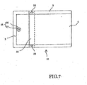
- Figs. 6 - 8 show still another embodiment of the plastic pouch of the present invention, where Fig. 6 is a schematic view explanatory of steps for manufacturing the pouch, Fig. 7 is a view of the pouch as taken from the front side of the pouch and Fig. 8 is an enlarged schematic view explanatory of steps for forming a folded-back section of the pouch.
- folded-back sections 32 are provided on both surfaces of the pouch, by folding back both the film 11 constituting the obverse surface of the pouch and the film 12 constituting the obverse surface of the pouch at same (i.e., corresponding) positions in a reverse Z configuration and Z configuration, respectively.
- holes 33 are formed in portions of the front-side film 11 and back-side film 12 constituting peripheral seal portions 3; more specifically, the holes 33 are formed in layers of the films 11 and 12 located inwardly of the respective outmost film layers (in this case, a total of four holes 33 are formed), as seen in Fig. 8 . Then, the outmost film layers of the films 11 and 12 are heat-sealed together through the holes 33.
- the peripheral seal portions 3 of the folded-back sections 32 can have enhanced heat-sealing intensity, which allows the one end portion of the pouch to rise upward with increased reliability as the pouch 31 is heated for cooking by the microwave oven.
- a vapor-evacuating seal section 36 having a weakened portion 37 is formed by heat-sealing together the obverse and reverse surface films at a position separate from the peripheral seal portions 3 and then forming an opening (e.g., through-hole) 37 in the resultant heat-sealed portion 36.
- the weakened portion 37 may of course be formed using any one of the other known methods, such as one that forms a half-through-hole, slit or unsealed portion instead of the through-hole.
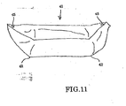
- Figs. 9 - 11 show still another embodiment of the plastic pouch of the present invention, where Fig. 9 is a schematic view explanatory of steps for manufacturing the pouch, Fig. 10 is a plan view of the pouch as taken from the back side of the pouch and Fig. 11 is a schematic view showing the pouch having been heated for cooking within a microwave oven.
- the film 12 constituting the reverse surface of the pouch is folded back in a Z configuration across the entire width of the pouch at a position adjacent to one end of the pouch to thereby provide a first folded-back section 42, and the film 12 is also folded back in a reverse Z configuration at a position adjacent to the other end of the pouch to thereby provide a second folded-back section 42.
- the interior pressure of the pouch 41 increases due to vapor etc. produced from the contents, so that the pouch 41 swells. During that time, the vapor also goes into the folded-back sections 42, so that the opposite pouch end portions rise upward starting at the corresponding folded-back sections 42 and thus the automatic opening mechanisms 5 are each held at a high position (see Fig. 11 ). Even after completion of the heating for cooking, when the interior pressure of the pouch 41 has fallen with each of the automatic opening mechanisms 5 brought into an opened position, the pouch 41 keeps substantially the same shape in a shrunken state, and thus, the pouch 41 can be used like a tray.
- the plastic pouch of the present invention having one or more folded-back sections, may be constructed with no such automatic opening mechanism provided.
- the automatic opening mechanism employed in the present invention.
- the automatic opening mechanism may be provided by projecting the peripheral-edge seal portion into the interior of the pouch in a U or V shape, forming, in the projected portion, an unsealed portion communicating with the outside of the pouch or punching such an unsealed portion.
- the automatic opening mechanism may comprise any conventionally-known means other than the above-described vapor-evacuating seal section; for example, the automatic opening mechanism may be provided using a member separate from the plastic pouch.
- the plastic pouch of the present invention may be of any suitable size and shape, and the films forming the pouch may be of any suitable materials.
- the contents to be packed in the plastic pouch of the present invention may be any type of food to be cooked by a microwave oven prior to use, such as not only food requiring a retort-sterilizing process, but also frozen food requiring no retort-sterilizing process.
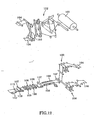
- a pouch material 101 in the form of a roll of plastic film laminate having a thermal adhesive (heat bonding) capability at least in its inner surface, is fed out via an unrolling mechanism 102 that unrolls the pouch material 101 from a horizontal rolled position to a vertical unrolled position. Then, the unrolled pouch material 101 is severed via a laser slitter 103, after which it is fed horizontally while being divided into a pair of upper and lower films 104 and 105 whose opposed surfaces have a thermal adhesive capability.
- These two films 104 and 105 are delivered via intermittently-feeding dancing rollers 106, then further fed via a feed roller 107 and thence superposed on each other through a printing-based positioning operation. After that, the superposed films 104 and 105 are heat-sealed together at their portions that will form a bottom portion and opposite side portions of the pouch, and then cut via a cutter unit 109 into each individual pouch. In this way, two rows of pouches can be manufactured simultaneously.
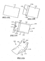
- Fig. 13 showing the plastic pouch, (a) is a perspective view of an obverse surface member, (b) is a perspective view of a reverse surface member, (c) is a bottom view of a pouch in an assembled state and (d) is a perspective view of the pouch heated by a microwave oven.
- the plastic pouch 110 generally comprises the obverse surface member 111 and reverse surface member 112, and a folded-back section 113 is provided on an intermediate portion of the reverse surface member 112 across the width of the reverse surface member 112.
- the folded-back section 113 is formed by folding back the reverse surface member 112, along a line extending widthwise (in a longitudinally-intermediate area of the reverse surface member 112) at right angles to opposite side edges of the member 112, and peripheral edge portions of the surface members 111 and 112 are heat-sealed together along their peripheral edges to provide sealed portions 114.
- one side of the pouch which will become the bottom of the pouch, is left unsealed to provide a filling opening 115.
- an opening 116 that automatically opens in response to an increase in the interior pressure of the pouch is formed, as necessary, as a through-hole passing through a heat-seal portion 117.
- the heat-seal portion 117 is formed separately from the peripheral-edge sealed portion 114 of the pouch, and the opening 116 is formed in this heat-seal portion 117.
- the pouch 110 where the folded-back section 113 communicating with the interior of the pouch is provided widthwise on an intermediate portion of the one surface member 112 of the flat-type pouch.
- the surface member 112 extending widthwise at right angles to the opposite sides, can have an increased length and thus can easily rise upward.
- the automatic opening portion 116 can be held at a high position (see (d) of Fig. 13 ).
- the ways of forming the folded-back section 113 and fixing the opposite ends 113a of the folded-back section 113 have great influences on the overall production efficiency.
- a portion of the obverse surface member 121 is folded to provide a folded-back section 123.
- the two pouches are made in a side-by-side relation to each other on the obverse and reverse surface members 121 and 122 with their top portions opposed to each other and their bottom portions facing outwardly away from each other.
- a plastic film laminate whose inner surface has a thermal adhesive capability, is severed and fed in such a manner that respective inner surfaces of the resultant two divided film members are opposed to each other, to provide obverse and reverse surface members 121 and 122, by means of a manufacturing line like that already explained above in relation to Fig. 12 .
- holes 123b are formed for fixing together, through heat-sealing, the opposite ends 123a of the folded-back section 123.
- the hole formation for fixing, through heat-sealing, the opposite ends 123a of the folded-back section 123 may be effected by forming the holes 123b in two inner surface member portions 121a and 121b folded to be sandwiched between the outermost portions of the obverse and reverse surface members 211 and 122 and hence located inwardly of the obverse surface member 121.
- the opposite ends 123a of the folded-back section 123 can be fixed by the obverse and reverse surface members 121 and 122 being heat-sealed together, through the holes 123b, in direct contact with each other.
- the holes 123b for fixing, through heat-sealing, the opposite ends 123a of the folded-back section 123 may be circular holes formed in the two surface member portions 121a and 121b, or oval holes 123 each continuously formed to extend over both of the surface member portions 121a and 121b.
- each of the holes 123b may be formed to extend over a pair of pouches manufactured in succession (one after another) on the manufacturing line so that semi-circular or semi-oval holes 123b are formed in each of the successive pouched, as illustrated in (c) of Fig. 15 .
- the number of hole-forming machines to be installed can be reduced by half.
- the obverse surface member 121 are folded along two separate lines thereof to thereby form two separate folded-back sections 123, after which longitudinal and transverse sealing 124a and 124b is performed on peripheral edge portions of the pouch with a filling opening 125 left unsealed and the ends 123a of each of the folded-back sections 123 are also fixed, through the holes 123b, by the transverse sealing 124b.
- heat-sealing 126 for forming an automatic opening portion is performed simultaneously with one of the longitudinal and transverse heat-sealing 124a and 124b which takes place closer to the automatic opening portion.
- the heat-sealing 126 for forming the automatic opening portion 127 is to be performed at a corner portion between the longitudinal and transverse heat-sealing 124a and 124b as illustrated in (a) of Fig. 16 , then the heat-sealing 126 may be performed during any one of the longitudinal and transverse heat-sealing 124a and 124b. If the heat-sealing 126 for forming the automatic opening portion 127 is to be performed adjacent to a middle portion of the longitudinal heat-sealing 124a as illustrated in (b) of Fig. 16 , then the heat-sealing 126 may be performed during the longitudinal heat-sealing 124a.
- the heat-sealed obverse and reverse surface members 121 and 122 are cut via a cutter unit into each individual pouch. In this way, two pouches can be manufactured simultaneously.
- a plastic pouch is manufactured by forming one widthwise folded-back section 123 on the obverse surface member 121 in communication with the interior of the pouch, heat-sealing together peripheral edge portions of the surface members and fixing the widthwise opposite ends 123a of the folded-back section 123, located outwardly of the sealed portions, to the obverse surface member 121. Because the folded-back section 123 is formed by folding a portion of the obverse surface member 121, it is possible to readily form the folded-back section 123 on the obverse surface member 121 in the form of a web fed both continuously and intermittently.
- the method of the present invention can readily manufacture plastic pouches, each having a folded-back section 123, in the two-row manufacturing fashion.
- the aforementioned step of forming the holes 123b for fixing the opposite ends of the folded-back section 123 may be performed by rotary die cutting during continuous feeding of the obverse and reverse surface members 121 and 122 or performed by a punch mechanism during intermittent feeding of the obverse and reverse surface members 121 and 122.
- folding of a portion of the obverse surface member 121 for the formation of the folded-back section 123 may be performed during continuous feeding of the obverse surface member 121 or after an intermittent feeding condition has been created via dancing rollers or the like. It is more preferable to fold the portion of the obverse surface member 121 during continuous feeding of the obverse surface member 121 in that stability of the folding step can be secured.
- the step of forming the holes 123b for fixing the opposite ends 123a of the folded-back section 123 and holes are formed in two obverse surface member portions 121, interposed between the folded-back sections 123, for fixation by heat-sealing (as in the case shown in Fig. 14 )
- Fixation of the opposite ends 123a of the folded-back section 123 need not necessarily be performed simultaneously with the heating-sealing 124 of the peripheral edge portions following the formation of the holes 123b.
- the opposite ends 123a of the folded-back section 123 may be fixed by an adhesive 128, such as a hot-melt adhesive, by a mechanical fixation means, such as a stapler or rivet, by welding based on supersonic sealing, or by any other suitable fixation method.
- the reverse surface member 121 may be folded at two portions thereof to form two folded-back sections 123 thereon, or one folded-back section 123 may be formed on each of the obverse and reverse surface members 121 and 122.
- the two rows of folded-back sections 123 may be oriented either in symmetrical relation to each other, or in asymmetrical relation to each other.
- the two rows need not necessarily be formed simultaneously and may be formed at differentiated timing (one after another) as long as formation of the two rows of folded-back sections 123 is completed before the heat-sealing 124 is performed.
- a portion of any one of the obverse and reverse surface members 121 and 122 may be folded to provide folded-back sections 123, and plastic pouches can be manufactured through manufacturing steps similar to those in the two-row manufacturing line.
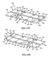
- the manufacturing method 130 of Figs. 18 and 19 is shown as applied to a three-row manufacturing line where three plastic pouches 110 are manufactured at a time. Where plastic pouches are manufactured by folding any one of the obverse and reverse surface members 121 and 122 at three separate portions thereof to provide three rows of folded-back sections 123, these plastic pouches can be manufactured through manufacturing steps similar to those in the already-described two-row manufacturing line, although not specifically shown.
- the folding at three separate portions need not necessarily be started at the same time.
- Timing for folding the three portions of the front or reverse surface member may be differentiated from one another; for example, the folding at one of the portions may be started after the folding at the other two portions has been started, in which case folded positions and folded amounts in the transverse or width direction of the front or reverse surface member 121 or 122 can be adjusted with ease.
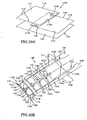
- the manufacturing method 130 is applied to the three-row manufacturing line and when folded-back sections 123 are to be formed on two portions of the obverse surface member 121 and on one portion of the rear surface member 122, if three rows of pouches are arranged in such a manner that opening portions 125, providing non-heat-sealed filling openings of two of the three pouches, are opposed to each other and heat-sealed bottom portions of one of these two pouches and the remaining one of the three pouches are opposed to each other as illustrated in (a) or (b) of Fig.
- plastic pouches can be manufactured with folding directions of the two folded-back sections 123 on the obverse surface member 121 asymmetric to each other (in the illustrated example of (a) of Fig. 18 ) or symmetric to each other (in the illustrated example of (b) of Fig. 18 ).
- the one folded-back section 123 can be formed substantially on the centerline of the width direction of the reverse surface member 122, while, in the illustrated example of (b) of Fig. 18 , the one folded-back section 123 can be formed on an end portion greatly deviated from the centerline of the width direction of the reverse surface member 122.
- the three pouches are arranged in such a manner that the non-heat-sealed opening portions 125 two of the three pouches are opposed each other and heat-sealed bottom portions of one of these two pouches and the remaining one of the three pouches are opposed to each other as illustrated in (a) or (b) of Fig. 18 , and where the sealed surface members are cut, via a cutter unit, into individual pouches at the last step of the manufacturing line, it can avoid wasteful trimmed portions from being produced due to the cutting, thereby achieving efficient use of the plastic film laminate.
- two folded-back section 123 are formed on two separate portions of the obverse surface member 121 and one folded-back section 123 is formed on a portion of the reverse surface member 122, and if three rows of pouches are arranged in such a manner that the non-heat-sealed opening portions 125 of two of the pouches are opposed to each other while the bottom portion of a middle one of the pouches and the non-heat-sealed opening portion 125 of the remaining one of the pouches are opposed to each other as shown in, for example, in (a) of Fig.
- the two folded-back section 123 can be formed on opposite widthwise end portions of the obverse surface member 121 and their respective folding directions can be set to be symmetric to each other, while the one folded-back section 123 can be formed on the centerline in the width direction of the reverse surface member 122.
- the other manufacturing steps of the plastic pouch manufacturing method applied to the three-row manufacturing line can be performed in generally the same manner as in the above-described method applied to the two-row manufacturing line and thus will not be described here.
- the instant embodiment of the manufacturing method can manufacture plastic pouches in the three-row manufacturing fashion, by forming three rows of folded-back sections 123 on the obverse and reverse surface members 121 and 122.
- each plastic pouch 110A is made to include a folding-back surface member 119 in addition to an obverse surface member 111 and reverse surface member 112, and a distal end portion of a folded-back section 113 of the pouch is hermetically sealed by heat-sealing 114A.
- Such a plastic pouch 110A can be made using, as a manufacturing line, facilities intended for manufacturing of a standing-type pouch, by providing the folding-back surface member 119 (129) instead of a bottom member.
- the manufacturing method 140 is applied to a two-row manufacturing line 120, for example, two separates plastic film laminates, each having a thermal adhesive capability in its inner surface, are supplied, and each end portion of each of the plastic film laminates is folded once to form the folded-back section 113. After that, holes 123b for fixing, by heat sealing, the opposite ends 123a of the folded-back section 123 are formed in two-layer overlapping portions at the opposite ends 123a.
- the holes 123b for fixing, by heat-sealing, the opposite ends 123a of the folded-back section 123 may be formed on the same positions and in the same shape as described above.
- the obverse surface member 121 is superposed on the upper surface of the folding-back surface member 129, while the reverse surface member 122 is superposed on the lower surface of the folding-back surface member 129.
- top sealing 124c of the folded-back section 123 as well as vertical and horizontal sealing 124a and 124b of peripheral edge portions of the pouch are effected by heat-sealing 124, but an opening portion 125, which will serve as a filling opening, is left in an opened state.
- the ends 123a of the folded-back section 123 are fixed by the horizontal sealing 124b via the holes 123b.
- any portions to be sealed to provide a pouch can be appropriately sealed even where the folding-back surface member 129 is used as a separate member.
- Subsequent heat-sealing for formation of the automatic opening portion and other openings, cutting of the sealed obverse and reverse surface members into each individual pouch may be performed in a similar manner to those in the above-described two-row manufacturing method 120.
- the sealed portion 124c is formed, by the heat-sealing 124, on the top portion of the folded-back section 123, there may be provided a trimming step, as necessary, for performing necessary trimming.
- the folded-back sections 123 are formed by the folding-back surface member 129 being supplied as a separate member as noted above, so that folded sections and holes 123b can be formed separately from the supply of the obverse and reverse surface members 121 and 122.
- a step of applying an adhesive 128 to fix the ends 123a of each of the folded-back section 123 may be provided.
- the ends 123a of each of the folded-back sections 123 may be fixed in any other suitable manner.
- the plastic pouch manufacturing method of the present invention is arranged to form the folded-back sections by folding a portion of either or both of the obverse and reverse surface members, and thus, it can readily form the folded-back sections 123 on the obverse and/or reverse surface members in the form of a web fed both continuously and intermittently.
- the method of the present invention can readily manufacture plastic pouches each having a folded-back section 123.
- the folded-back sections can be formed with an even further ease by feeding the obverse and reverse surface members fed intermittently rather than continuously.
- plastic pouch manufacturing method of the present invention can facilitate manufacturing of plastic pouches in a two-row manufacturing line where plastic pouches are manufactured in two rows separate from each other in the width direction.
- the plastic pouch manufacturing method of the present invention it is possible to manufacture pouches by combining not only the obverse and reverse surface members but also the folding-back surface member, and thus, pouches, each including the folded-back section, can be manufactured using a conventional bag making machine for manufacturing standing-type pouches.
- the plastic pouch manufacturing method of the present invention can facilitate manufacturing of plastic pouches in a three-row manufacturing line where plastic pouches are manufactured in three rows separate from one another in the width direction, by forming three folded-back sections on three portions of any one of the obverse and reverse surface members, or forming two folded-back sections on two portions of any one of the obverse and reverse surface members and one folded-back sections on one portion of the other of the obverse and reverse surface members.
- plastic pouch manufacturing method of the present invention it is possible to readily manufacture plastic pouches, each having a folded-back section, irrespective of the folded-back direction of the folded-back sections, by forming the folded-back sections in the same or different folded-back directions or a combination thereof.
- the plastic pouch manufacturing method of the present invention it is possible to readily form the folded-back sections even on the surface member to which tension is applied, by forming the folded-back sections at differentiated timing (one after another) rather than at the same time, with the result that pouches, each including the folded-back section, can be manufactured with ease.
- the widthwise opposite ends of the folded-back section, located outwardly of the sealed portions can be fixed with ease by forming holes in portions of the two surface member portions sandwiched between the folded-back sections and fixing the opposite ends by heat sealing; thus, the opposite ends of each of the folded-back sections can be fixed with the inner surfaces of the obverse and reverse surface members held in direct contact with each other and heat-sealed together through the holes thus formed in the two surface members.
- the formation of the holes is performed during a continuous or intermittent feed of the obverse and reverse surface members or folding-back surface member; thus, the folded-back sections can be formed with each by forming the holes and performing the heat-sealing irrespective of whether the surface members are fed continuously or intermittently.
- the widthwise opposite ends of the folded-back section, located outwardly of the sealed portions can be fixed with ease by any one of an adhesive, mechanical fixation and welding.
- the automatic opening portion that can be automatically opened in response to an internal vapor pressure can be readily formed in a position located inwardly of the heat-sealed peripheral edge portions, and such an automatic opening portion allows heating by a microwave oven to be performed safely and with ease.
- the plastic pouch manufacturing method of the present invention it is possible to readily form the automatic opening portion by forming a head-sealed portion simultaneously with the heat-sealing of peripheral edge portions and then forming a through-hole in the head-sealed portion.
- Fig. 22 showing the plastic pouch, (a) is a perspective view of a film member, (b) is a bottom view of an assembled pouch, and (c) is a perspective view of the pouch heated by a microwave oven.
- This plastic pouch 210 is formed of the film member 211, and a folded-back section 213 is formed by folding back, in a substantial Z configuration, the film member 211 along a line extending widthwise (in a longitudinally-intermediate area of the film member 211) at right angles to opposite side edges of the member 112.
- Peripheral-edge sealed portion 214 is formed by leading-end heat-sealing 214a and heat-sealing of a sealing portion 214c of the folded-back section 213.
- an automatic opening portion 216 that automatically opens in response to an increase in the interior pressure of the pouch is formed, as necessary, as a through-hole passing through a heat-sealed portion 217.
- the heat-sealed portion 217 is formed separately from the peripheral sealed portion 214, and the opening 216 is formed in this heat-sealed portion 217.
- the folded-back section 213 communicating with the interior of the flat-type pouch is provided widthwise on an intermediate portion of the film member 211 communicating with the interior of the pouch, so that, as the folded-back section 213 is swollen by the increased interior pressure of the pouch, a portion of the film member 211, extending widthwise at right angles to the opposite sides, can have an increased length and thus can easily rise upward.
- the opening 216 can be held at a high position (see (c) of Fig. 22 ).
- the manufacturing/packing method is arranged to pack the desired contents into the plastic pouch 210 of Fig. 22 while making the pouch 210 by feeding the pouch 210 in a posture where the wide sides of the pouch are oriented vertically while the narrow sides are oriented horizontally. Folded-back section 213 will be formed along the pouch feeding direction.
- a plastic film laminate 221 having a thermal adhesive capability in its inner surface, is unrolled or played out and led, via a plurality of supply rollers 222, to a former 223.
- the plastic film laminate 221 is curved into a cylindrical shape, and then opposite side edge portions of the cylindrically-curved film laminate 221 are superposed on each other to provided a superposed section 224.
- Proximal end of the superposed section 224 is bent at a subsequent step.
- a length L measured from the bent proximate end of the superposed section 224 has a length L is equal to a sum of a length L1 of the folded-back section 213 of the pouch 210 and a length L2 of the sealing section 214c necessary for closing and sealing the leading end of the folded-back section 213 at this step.
- the length of the superposed section 224 is greater, by the length L1 of the folded-back section 213, than a superposed section of a conventional pillow package.
- an adhesive 228, such as a hot-melt adhesive is applied, via an adhesive application device 27, to the opposite ends 213a of the folded-back section 213 of the plastic pouch 210, which will be bent inward, at a subsequent step, from the proximal end, in the superposed section 224 of the substantially-cylindrical structure 226; in this case, the adhesive 228 is applied at intervals corresponding the width of the plastic pouch 210 in use condition of the pouch.
- the superposed section 224 of the substantially-cylindrical structure 226 is delivered to a pressing roller 229, by which it is pressed so that the surface having the adhesive 228 applied thereto is bent inward from the proximal end and the opposite ends 213a of the folded-back section 213 are adhesively fixed.
- the leading end of the substantially-cylindrical structure 226 is subjected to leading-end sealing 231 by a heat-seal device 230, and the thus heat-sealed leading end forms one of the leading-end seals 214a.
- desired contents 232 are packed into the substantially-cylindrical structure 226 closed at its leading end via the leading-end seal 231, and then the trailing end is subjected to trailing-end sealing 231 by the heat-seal device 230; the thus heat-sealed trailing end forms the other of the leading-end seals 214a.
- the plastic pouch 210 is hermetically sealed with the contents packed therein.
- the plastic film laminate 221 is cut, via the heat-seal device 230, at a position thereof behind the trailing-end seal 234, to thereby provide a separated plastic pouch 21.
- the trailing-end sealing 234 of a preceding one of every pair of successive plastic pouches 210 and the leading-end sealing 231 of the succeeding plastic pouch 210 are performed simultaneously by the heat-seal device 230.
- an automatic opening portion 216 that can open in response to a vapor pressure in the interior of the pouch 210 is formed in the plastic film laminate 221.
- the heat-sealed portion 217 is formed by the heat seal device 230 simultaneously with the leading-end sealing 231 and trailing-end sealing 234 and then a through-hole is formed in the heat-sealed portion 217, to thereby provide the automatic opening portion 216.
- the inner pressure increased due to heating by the microwave oven can be automatically evacuated through the automatic opening portion 216.
- the plastic pouch manufacturing/packing method of the present invention is arranged to superpose the opposite widthwise end edge (i.e., side edge) portions of the plastic film 221 and then perform sealing of the folded-back section 213 and sealing section 214c at the leading end of the folded-back section 213 by means of the pillow-seal device 225; with these arrangements, the method of the present invention can manufacture a pouch 210 including the folded-back section 213. Further, the method of the present invention can pack desired contents 232 while manufacturing the plastic pouch 210, by packing the contents 232 in the interior of the pouch between the leading-end seal 231 and the trailing-end seal 234. As a result, the manufacturing/packing method of the present invention can perform the plastic pouch manufacturing and contents packing with utmost efficiency.
- the fixation of the opposite ends 213a of the folded-back section 213 can be easily performed by just folding the superposed section 224 after application of the adhesive 228.
- the trailing-end sealing 234 of the substantially-cylindrical structure 226 of the preceding plastic pouch and the leading-end sealing 231 of the substantially-cylindrical structure 226 of the succeeding plastic pouch are performed simultaneously.
- the plastic pouch manufacturing and contents packing can be carried out with utmost efficiency.
- the automatic opening portion 216 that can open in response to a vapor pressure in the interior of the pouch 210 allows the inner pressure, increased due to heating by the microwave oven, to be automatically evacuated therethrough.
- the automatic opening portion 216 is provided by forming, via the heat-seal device 230, the heat-sealed portion 217 simultaneously with the leading-end sealing 231 and trailing-end sealing 234 and then forming a through-hole in the heat-sealed portion 217 via a punch device 236.
- the method of the present invention can readily provide the automatic opening portion 216.
- the present invention is not so limited; for example, the opposite ends 213a can also be fixed easily by a mechanical means, such as a stapler or rivet, or by welding based on supersonic sealing.
- the plastic pouch of the present invention can be suitably used as a microwave-cooking pouch for packing therein retort food, in liquid or solid form or in a mixture of liquid and solid materials.
Description
- The present invention relates to flat-type plastic pouches according to the preamble of
claim 1, formed by heat-sealing peripheral edge portions of plastic films constituting front and back surfaces, i.e. obverse and reverse surfaces, of the pouches, and methods for manufacturing the plastic pouches. The plastic pouch of the present invention can be suitably used as a microwave-cooking pouch having contents, such as retort food in liquid or solid form or in a mixture of liquid and solid materials, packed therein. - When a packaging bag, having retort food, frozen food or the like packed therein in a hermetically sealed state, is heated by a microwave oven, the pressure in the interior of the packaging bag increases due to vapor etc. produced from the heated contents, and thus, the packaging bag may burst so that the packed contents scatter and soil the interior of the microwave oven and even inflict harm, such as a burn, on a human body.
- In order to avoid the aforementioned inconveniences, it has been conventional to partly open the packaging bag or make a hole in the body of the packaging bag before the packaging bag is subjected to heating by a microwave oven, so as to discharge vapor etc. produced within the bag and thereby prevent the bag from bursting.
- However, such a conventional solution would require extra time and labor on the part of general consumers. Also, because the vapor produced due to the heating by the microwave oven is immediately discharged outside the packaging bag, a steaming effect by the vapor would be considerably reduced so that the food undesirably deteriorates in flavor.
- To avoid the problem, a variety of plastic pouches have so far been proposed which are equipped with a mechanism that automatically opens, in response to an increase in the interior pressure of the pouch due to heating by a microwave oven, so that the increased interior pressure is allowed to automatically escape from the interior of the pouch.
- As the plastic pouches equipped with such an automatically-opening mechanism, there have been known various types of plastic pouches, such as standing-type pouches that are heated in a self-erected position within a microwave oven (see, for example, Japanese Patent Application Laid-open Publication Nos.
2002-249176 2003-192042 2002-80072 2001-106270 HEI-8-25583 - Of these pouches, the most superior in terms of productivity and cost is the flat-type pouch. However, because the opening portion of the flat-type pouch can not be held stably at a high position during cooking by the microwave oven and after the pouch automatically opens due to an increase in the interior pressure, the flat-type pouch would present the inconvenience that the contents of the pouch undesirably spout or leak out of the automatically-opening portion.
- For this reason, it has heretofore been proposed to employ an auxiliary device, such as an item packaging box, for holding the opening portion of the flat-type microwave-oven-cooking pouch (see Japanese Patent Application Laid-open Publication No.
2003-170930
European patent EP 0 256 791 discloses a plastic pouch according to the preamble ofclaim 1. - In view of the foregoing, it is an object of the present invention to provide a flat-type plastic pouch which can be manufactured efficiently at low cost and which, when heated for cooking in a flatly-laid position within a microwave oven, allows its opening portion, automatically opening in response to an increase in the interior pressure of the pouch, to be stably held at a high position, without using any auxiliary device.
- It is another object of the present invention to provide a plastic pouch manufacturing method which can manufacture a plastic pouch with a high efficiency.
- It is still another object of the present invention to provide a plastic pouch manufacturing/packing method which can manufacture a plastic pouch and pack contents into the pouch with a high efficiency.
- As a result of deliberate study by the inventors etc., it has been found that the above-discussed inconveniences can be effectively avoided by folding at least one of pouch-forming films across the entire width of a pouch to be manufactured and then heat-sealing peripheral edge portions of the films to thereby form a folded-back section communicating with the body of the pouch.
- Namely, the following structural arrangements in items 1 - 11 below are employed in the plastic pouch of the present invention.
- 1. A plastic pouch comprising an obverse surface film and a reverse surface film,
a folded-back section communicating with a body of said plastic pouch formed, on at least one position of said plastic pouch, by folding back, across the entire width of the pouch, at least one of said obverse surface film and said reverse surface film and heat-sealing peripheral edge portions of the pouch, and
an automatic opening mechanism formed at or near an end portion of said plastic pouch located near said folded-back section, wherein said automatic opening mechanism automatically opens as said plastic pouch is heated by a microwave oven. - 2. A plastic pouch as set forth in
item 1 wherein the folded-back sections are formed on both of said obverse surface film and said reverse surface film - 3. A plastic pouch as set forth in
items - 4. A plastic pouch as set forth in
items - 5. A plastic pouch as set forth in any one of items 1 - 4 wherein the folded-back section is formed by folding back the surface film in a Z configuration.
- 6. A plastic pouch as set forth in any one of items 1 - 4 wherein the folded-back section is formed by folding back the surface film in a Z configuration and then further folding back the surface film in a reverse Z configuration.
- 7. A plastic pouch as set forth in any one of items 1 - 6 wherein, in a peripheral-edge seal portion of said folded-back section, holes are formed in film layers located inwardly of outmost film layers of said obverse surface film and said reverse surface film that form peripheral-edge sealed portions of each of the folded-back sections, and the outmost film layers of said obverse surface film and said reverse surface film are heat-sealed together through the holes.
- 8. A plastic pouch as set forth in any of
items 1 to 7 wherein said automatic opening mechanism is formed adjacent to a peripheral-edge sealed portion at the end portion of said plastic pouch. - 9. A plastic pouch as set forth in item 8 wherein said automatic opening mechanism is formed by providing, on the peripheral-edge sealed portion at the end portion of said plastic pouch, a projection having a distal end portion projected toward an interior of said plastic pouch.
- 10. A plastic pouch as set forth in any one of
items 1 to 7 wherein said automatic opening mechanism is formed separately from a peripheral-edge sealed portion at an end portion of said plastic pouch. - 11. A plastic pouch as set forth in any one of
items 1 to 10 wherein said automatic opening mechanism is in the form of a vapor-evacuating seal section having a weakened portion.
The plastic pouch of the present invention can be manufactured efficiently at low cost similar to the cost required of the conventional flat-type pouch, without additional components and manufacturing steps required of the standing-type and branch-type pouches. Further, when the plastic pouch of the invention is to be horizontally laid flat in a microwave oven so as to be heated for cooking, the automatic opening portion that automatically opens in response to an increase in the interior pressure of the pouch can be stably held at a relatively high position without using any auxiliary device, with the result that it is possible to prevent unwanted blowout or leakage of the contents out of the opening portion.
Further, it has been found even more advantageous to fix the widthwise opposite ends of the folded-back section to the body of the pouch, in order to prevent the plastic pouch from being damaged by the heat sealing so that the automatic opening portion can be reliably held at a high position, or, in order to prevent the folded-back section from projecting outwardly for possible interference or hindrance during packing of the contents into the pouch and distribution or transport of the pouch after packing of the contents (even in the case where no such automatic opening portion is provided). Thus, the inventors have completed an efficient method for manufacturing such an advantageous plastic pouch.
The following structural arrangements in items 12 - 23 are employed in the plastic pouch manufacturing method of the present invention. - 12. A method for manufacturing a plastic pouch as set forth in items 1-11, including a widthwise folded-back section provided on at least one position of an obverse surface member and reverse surface member in communication with an interior of the plastic pouch, peripheral edge portions of the pouch being heat-sealed, and opposite widthwise ends of said folded-back section, located outwardly of sealed portions of said folded-back section, being fixed to said obverse surface member or said reverse surface member,
wherein said method forms said folded-back section by folding one portion of at least one of said obverse surface member and said reverse surface member,
the opposite widthwise ends of said folded-back section, located outwardly of the sealed portions of said folded-back section, are fixed by forming holes in two portions of the surface members sandwiched between the folded-back sections and then heat-sealing the opposite widthwise ends.
According to the plastic pouch manufacturing method, in manufacturing a plastic pouch where a widthwise folded-back section is provided, on at least one position of the obverse surface member and reverse surface member, in communication with the interior of the plastic pouch, the peripheral edge portions of the pouch are heat-sealed, and where the opposite widthwise ends of the folded-back section, located outwardly of sealed portions of the folded-back section, are fixed to the obverse surface member or the reverse surface member, the folded-back section is formed by folding one portion of at least one of the obverse surface member and the reverse surface member. Thus, it is possible to readily form the folded-back section on the obverse or reverse surface member which is in the form of a web fed both continuously and intermittently. - 13. A method for manufacturing a plastic pouch as set forth in
item 12 wherein formation of said folded-back section is performed on the at least one of said obverse surface member and said reverse surface member that are fed continuously.
According to the plastic pouch manufacturing method, the formation of the folded-back section is performed on at least one of the obverse and reverse surface members being fed in a continuous manner, so that the folded-back section can also be readily formed from the continuously-fed obverse and/or reverse surface members.
According to the plastic pouch manufacturing method, fixation of the opposite widthwise ends of the folded-back section, located outwardly of the sealed portions of the folded-back section, is effected by forming holes in two portions of the surface members between the folded-back sections and then heat-sealing the opposite widthwise ends. Thus, the opposite widthwise ends can be fixed together by heat-sealing, through the holes formed in the portions of the two surface members, with the inner surfaces of the upper and lower surface members placed in contact with each other. - 14. A method for manufacturing a plastic pouch as set forth in
item 12 wherein formation of said folded-back section is performed on the at least one of said obverse surface member and said reverse surface member after continuous feeding of the at least one of said obverse surface member and said reverse surface member is converted into intermittent feeding.
According to the plastic pouch manufacturing method, the formation of the folded-back section is performed on at least one of the obverse and reverse surface members being fed in an intermittent manner, so that the folded-back section can also be readily formed from the intermittently-fed obverse and/or reverse surface members. - 15. A method for manufacturing a plastic pouch as set forth in any one of items 12 - 14 wherein formation of said folded-back section is performed on two portions of any one of said obverse surface member and said reverse surface member, or on one portion of each of said obverse surface member and said reverse surface member, so as to manufacture plastic pouches in two rows.
According to the plastic pouch manufacturing method, the folded-back section is formed on two portions of any one of the obverse surface member and the reverse surface member, or on one portion of each of the obverse surface member and the reverse surface member, so as to manufacture plastic pouches in two rows. - 16. A method for manufacturing a plastic pouch as set forth in any one of items 12 - 15 wherein the plastic pouch is manufactured using, in addition to said obverse surface member and said reverse surface member, a folding-back surface member to be used for forming said folded-back section.
According to the plastic pouch manufacturing method, the plastic pouch is manufactured using not only the obverse surface member and the reverse surface member, but also a folding-back surface member to be used for forming the folded-back section. Thus, it is possible to manufacture a plastic pouch from a combination of not only the obverse and reverse surface members but also the folding-back surface members, using a conventional bag making machine for standing-type pouches. - 17. A method for manufacturing a plastic pouch as set forth in any one of items 12 - 14 wherein formation of said folded-back section is performed on three portions of any one of said obverse surface member and said reverse surface member, or on two portions of any one of said obverse surface member and said reverse surface member and on one portion of other of said obverse surface member and said reverse surface member, so as to manufacture plastic pouches in three rows.
According to the plastic pouch manufacturing method, the folded-back section is formed on three portions of any one of the obverse surface member and the reverse surface member, or on two portions of any one of the obverse surface member and the reverse surface member and on one portion of the other of the surface members, so as to manufacture plastic pouches in three rows. By thus forming the folded-back sections on three portions, the present invention can facilitate three-row manufacturing where plastic pouches are manufactured in three rows separate from one another in a width direction of the surface members. - 18. A method for manufacturing a plastic pouch as set forth in any one of items 12 - 17 wherein the folded-back sections of individual plastic pouches to be manufactured are formed using a same folding direction or different folding directions or a combination of the same folding direction and different folding directions.
According to the plastic pouch manufacturing method, the folded-back sections of the individual plastic pouches are formed using the same folding direction or different folding directions or a combination of the same folding direction and different folding directions. With such arrangements, the present invention can manufacture plastic pouches irrespective of the respective folded-back directions of the folded-back sections. - 19. A method for manufacturing a plastic pouch as set forth in any one of items 12 - 18 wherein formation of said folded-back section is performed at differentiated timing.
According to the plastic pouch manufacturing method, the formation of the folded-back section is performed at differentiated timing, or one another. By thus performing the formation of the folded-back sections at differentiated times rather than at the same time, the present invention allows the folded-back section to be readily formed even on the surface member subjected to tension. - 20. A method for manufacturing a plastic pouch as set forth in any one of
items 12 to 19 wherein said holes are formed in each of the two portions of the surface members or in the folding-back surface member, or formed to extend over the two portions of the surface members.
According to the plastic pouch manufacturing method, the above-mentioned holes are formed in each of the two portions of the surface members or in the folding-back surface member, or formed to extend over the two portions of the surface members. Thus, the opposite widthwise ends can be fixed together, even through the holes formed to extend over the two portions of the surface members, with the inner surfaces of the upper and lower surface members placed in contact with each other. - 21. A method for manufacturing a plastic pouch as set forth in any one of
items 12 to 20 wherein formation of said holes is performed during continuous feeding or intermittent feeding of said obverse surface member and said reverse surface member or of the folding-back surface member.
According to the plastic pouch manufacturing method, formation of the holes is performed during continuous feeding or intermittent feeding of the obverse and reverse surface members or of the folding-back surface member. With such arrangements, the holes can be formed to appropriately fix the folded-back section irrespective of whether the surface members are fed continuously or intermittently. - 22. A method for manufacturing a plastic pouch as set forth in any one of items 12 - 21 which further comprises forming an automatic opening portion that can open in response to a vapor pressure within the pouch is formed inwardly of a heat-sealed peripheral edge portion of the plastic pouch.
According to the plastic pouch manufacturing method, the automatic opening portion that can open in response to a vapor pressure within the pouch is formed inwardly of the heat-sealed peripheral edge portion of the plastic pouch. With such arrangements, the present invention can readily form the automatic opening portion and thus facilitates heating of the pouch by a microwave oven. - 23. The method for manufacturing a plastic pouch set forth in item 22, which is characterized in that the automatic opening portion is formed by forming a heat-sealed portion simultaneously with heat-sealing of the peripheral edge portion of the pouch and then forming a through-hole in the heat-sealed portion.
According to the plastic pouch manufacturing method, the automatic opening portion is formed by forming a heat-sealed portion simultaneously with heat-sealing of the peripheral edge portion of the pouch and then forming a through-hole in the heat-sealed portion. The through-hole formed in the heat-sealed portion can be provided as the automatic opening portion. -
-
Fig. 1 is a schematic view explanatory of steps for manufacturing an embodiment of a plastic pouch of the present invention; -
Fig. 2 is a view of the plastic pouch, manufactured through the steps ofFig. 1 , taken from the back side of the pouch; -
Fig. 3 is a schematic view showing the plastic pouch ofFig. 2 heated within a microwave oven; -
Fig. 4 is a schematic view explanatory of steps for manufacturing another embodiment of a plastic pouch of the present invention; -
Fig. 5 is a view of the plastic pouch, manufactured through the steps ofFig. 4 , taken from the back side of the pouch; -
Fig. 6 is a schematic view explanatory of steps for manufacturing still another embodiment of a plastic pouch of the present invention; -
Fig. 7 is a view of the plastic pouch, manufactured through the steps ofFig. 6 , taken from the front side of the pouch; -
Fig. 8 is a schematic view explanatory of steps for forming a folded-back section of the pouch shown inFig. 7 ; -
Fig. 9 is a schematic view explanatory of steps for manufacturing still another embodiment of a plastic pouch of the present invention; -
Fig. 10 is a view of the plastic pouch, manufactured through the steps ofFig. 9 , taken from the back side of the pouch; -
Fig. 11 is a schematic view showing the plastic pouch ofFig. 10 heated within a microwave oven; -
Fig. 12 is a schematic view showing an ordinary manufacturing line for manufacturing a conventional flat-type pouch; -
Fig. 13 shows a plastic pouch to be manufactured in accordance with the present invention, where (a) is a perspective view of an obverse surface member, (b) is a perspective view of a reverse surface member, (c) is a bottom view of the pouch in an assembled state and (d) is a perspective view of the pouch in a heated condition; -
Fig. 14 is a schematic view explanatory of steps of a plastic pouch manufacturing method in accordance with an embodiment of the present invention; -
Fig. 15 is a schematic view explanatory of positions of holes for fixing a folded-back section according to the embodiment of the plastic pouch manufacturing method; -
Fig. 16 is a schematic view explanatory of a position of an automatic opening portion according to the embodiment of the plastic pouch manufacturing method; -
Fig. 17 is a schematic view explanatory of another way of fixing the folded-back section according to the embodiment of the plastic pouch manufacturing method; -
Fig. 18 is a schematic view explanatory of a plastic pouch manufacturing method in accordance with another embodiment of the present invention, where (a) and (b) show steps of the method; -
Fig. 19 is a schematic view explanatory of steps of a plastic pouch manufacturing method in accordance with another embodiment of the present invention and an area where a plastic pouch is severed; -
Fig. 20 is a view explanatory of a plastic pouch to be manufactured by a plastic pouch manufacturing method in accordance with still another embodiment of the present invention and steps of the manufacturing method; -
Fig. 21 is a schematic view and a fragmentary enlarged view of a manufacturing line according to an embodiment of a plastic pouch manufacturing/packing method of the present invention; and -
Fig. 22 shows a plastic pouch to be manufactured in accordance with the present invention, where (a) is a perspective view of a film member, (b) is a bottom view of the pouch in an assembled state, (c) is a perspective view of the pouch heated by a microwave oven. - Plastic film forming the plastic pouch of the present invention is made of a heat-sealable plastic material that is conventionally used in manufacturing of packaging bags. Among examples of such a plastic material are a uni-layered film or sheet of heat-sealable thermoplastic resin, multi-layered film comprising heat-sealable thermoplastic resin laminated with other thermoplastic resin, etc.
- As the heat-sealable plastic material, there may be used, for example, conventionally-known low-density polyethylene, linear low-density polyethylene, medium-density polyethylene, high-density polyethylene, polypropylene, propylene-ethylene copolymer, ethylene-vinyl acetate copolymer, ethylene-series unsaturated carboxylic acid, olefin-series resin graft-modified with an anhydride of the ethylene-series unsaturated carboxylic acid, polyamide or copolyamide having a relatively low melting point or softening point, polyester or copolyester resin, polycarbonate, or the like.
- Further, as the other thermoplastic resin laminated with the heat-sealable plastic material, there may be used a film of heat-sealable or heat-sealable thermoplastic resin, any of various barrier films, or the like.
- Among examples of the above-mentioned thermoplastic resin are polyolefin resin, such as crystalline polypropylene, crystalline propylene-ethylene copolymer, crystalline polybuten-1, crystalline poly 4-methylpentene-1, low-, medium- or high-density polyethylene, ethylene-vinyl acetate copolymer (EVA), saponified ethylene-vinyl acetate copolymer, ethylene-ethyl acrylate copolymer (EEA) or ion-cross-linked-olefin copolymer; aromatic vinyl copolymer, such as polystylene or stylene-butadiene copolymer; vinyl halide polymer, such as polyvinyl chloride or vinylidene chloride resin; polyacrylic resin; nitrile polymer, such as acrylonitrile-styrene copolymer or acrylonitrile-styrene-butadiene copolymer; polyester, such as polyethylene terephthalate or polytetramethylene terephthalate; any of various polycarbonates; fluorine-series resin; or polyacetal resin, such as polyoxymethylene. One of the above-mentioned thermoplastic resin may be used solely, or two or more types of the above-mentioned thermoplastic resin may be used in a blended combination. Further, the thermoplastic resin may be used with any of various additive agents contained therein.
- Further, the various barrier films may include organic resin films, such as a silica-deposited polyester film, alumina-deposited polyester film, silica-deposited nylon film, alumina-deposited nylon film, alumina-deposited polypropylene film, carbon film-deposited polypropylene film, carbon film-deposited nylon film, binary-deposited film formed by simultaneously depositing alumina and silica on a base film, such as a polyester or nylon film, co-extruded film of nylon-6/ nylon MXD(m-xylylenediamine)-6, co-extruded film of polyprorylene/ ethylene-vinyl alcohol copolymer, polyvinyl alcohol-coated polypropylene film, polyvinyl alcohol-coated nylon film, polyacrylic acid-series-resin-coated polyester film, polyacrylic acid-series-resin-coated nylon film, polyacrylic acid-series-resin-coated polypropylene film, polyglycol acid-resin-coated polyester film, polyglycol acid-resin-coated nylon film and polyglycol acid-resin-coated polypropylene film, as well as films formed by coating a hybrid coating material of organic resin or non-organic material onto a base film, such as a polypropylene film. One or more types of the above-mentioned barrier films may be used solely or in a blended combination.
- Further, as the other thermoplastic resin laminated with the heat-sealable plastic material, there may be used a film of oxygen-absorbing resin, or a laminated film made of oxygen-absorbing resin and other thermoplastic resin.
- As the oxygen-absorbing resin, there may be used (1) resin that in itself has an oxygen-absorbing capability, or (2) a resin composition containing an oxygen absorbent in thermoplastic resin that has or does not have an oxygen-absorbing capability. There is no particular limitation on the thermoplastic resin forming the oxygen-absorbing resin composition mentioned in item (2) above; either thermoplastic resin having an oxygen barrier capability or thermoplastic resin having no oxygen barrier capability. Using the resin, which itself has an oxygen-absorbing capability or oxygen barrier capability, as the thermoplastic resin forming the resin composition mentioned in item (2) above is preferable in that entry of oxygen into a container can be effectively prevented by a combination with the oxygen-absorbing effect provided by the oxygen absorbent.
- Among examples of the resin that in itself has an oxygen-absorbing capability is one that takes advantage of oxidization reaction of the resin. For example, there may be used resin that is formed by adding organic salt containing, as an oxidization catalyst, transition metal, like cobalt, rhodium or copper, or photosensitizer to an oxidizing organic material, such as polybutadiene, polyisoprene, polyprorylene, ethylene-carbon monoxide copolymer, nylon-6, nylon-12 or m-xylylenediamine nylon (MX). In the case where such an oxygen absorbent is used, further advantageous results can be achieved by irradiating high-energy rays, such as ultraviolet rays or electronic rays.
- Any one of the oxygen absorbents conventionally employed in this type of application may be used as the oxygen absorbent contained in the thermoplastic resin; however, in general, an oxygen absorbent, which has a reducing capability and substantially insoluble in water. As a suitable example, there may be used an oxygen absorbent in the form of metal powder having a reducing capability, which for example includes, as a primary component, any one of, or a combination of two or more, of reducing iron, reducing zinc and reducing tin; low-order metallic oxide, such as FeO or Fe3O4; and a reducing metallic compound, such as iron carbide, ferro silicon, iron carbonyl or iron hydroxide. Among particularly preferable examples of the oxygen absorbent is reducing iron, such as: one formed by reducing oxidized iron, obtained for example during production of steel, with coke to thereby produce sponge iron, then crushing the sponge iron, and thence finish-reducing the crushed sponge iron in hydrogen gas or dissociated ammonia gas; or one formed by electrolytic decomposition of iron from aqueous iron chloride obtained during acid cleaning, then crushing the iron and thence reducing the crushed iron.
- As necessary, the oxygen absorbent may be used in combination with a pro-oxidant, such as a hydroxide of alkali metal or alkaline earth metal or an electrolyte of carbonate, sulfite, thiosulfate, triphosphate, diphosphate, organic acid salt, halide or the like, and/or with an assistant, such as activated carbon, activated alumina or white clay. Among particularly preferable examples of the pro-oxidant are sodium chloride, calcium chloride or a combination of sodium chloride and calcium chloride.
- In the case where reducing iron and pro-oxidant are used in combination, the combination ratio is preferably set, assuming the total amount to be 100 part by weight, such that the reducing iron is in an amount of 99 - 80 part by weight while the pro-oxidant is in an amount of 1 - 20 part by weight; especially, it is preferable that the reducing iron be in an amount of 98 - 90 part by weight and the pro-oxidant be in an amount of 2 - 10 part by weight.
- Among examples of the other oxidant absorbent is a high molecular compound having a polyhydric phenol within a skeleton, such as polyhydric phenol-contained phenol-aldehyde resin. Further, any one of erythorbic acid, erythorbic acid, tocopherol, which are water-soluble substances, and salts of these substances may be suitably used. Of these oxidant-absorbing substances, the reducing iron and ascorbic acid-series compound are the most preferable.
- Further, the above-mentioned resin that in itself has an oxygen-absorbing capability may be contained, as an oxygen absorbent, in the thermoplastic resin.
- It is generally preferable that each of the above-mentioned oxygen absorbents have an average grain diameter of 50 µm or less, particularly 30 µ m or less. If transparency or translucency is required, it is preferable that each of the above-mentioned oxygen absorbents have an average grain diameter of 10 µ m or less, particularly 5 µm or less. It is preferable that the oxygen absorbent be contained in the resin in an amount of 1 - 70 percent by weight, particularly 5 - 30 percent by weight.
- In the present invention, a packaging bag designed for heating by a microwave oven is made by heat-sealing an unstretched (unoriented) or uniaxially- or biaxially-stretched film, formed of the above-mentioned plastic material, in the conventional manner. If the film is a laminated film formed by heat-sealable thermoplastic resin and nonheat-sealable thermoplastic resin, the film is heat-sealed in such a manner that a layer of the heat-sealable thermoplastic resin forms the reverse surface of the bag.
- Next, a description will be given about a construction of the flat-type plastic pouch of the present invention, with reference to the drawings, although specific examples to be described below are in no way intended to limit the present invention.
-
Figs. 1 - 3 show an embodiment of the plastic pouch of the present invention, whereFig. 1 is a schematic view explanatory of steps for manufacturing the pouch andFig. 2 is a view of the pouch as taken from the back side of the pouch. -
Fig. 3 is a schematic view showing the pouch of the present invention heated in a microwave oven; more specifically, (a) shows the pouch being heated for cooking in an unopened state, while (b) shows the pouch having been completely heated for cooking in a partly-opened state. - The
pouch 1 of the present invention is made by superposing afilm 11 constituting the obverse surface of the pouch to be manufactured and anotherfilm 12 constituting the reverse surface of the pouch to be manufactured upon each other and heat-sealing together respective peripheral edge portions of the twofilms film 12 constituting the reverse surface of the pouch is folded back in a Z configuration across the entire width of the pouch and the respective peripheral edge portions of the twofilms filling opening 4 for filling the pouch with desired contents, so as to form a folded-backsection 2 communicating with the body of the pouch. On the other narrow-side end portion, opposite from the fillingopening 4, a vapor-evacuating seal section, having a weakened portion, is formed by projecting a peripheral-edge seal portion toward the interior of the pouch in a U shape and then forming an opening (e.g., through-hole)portion 7 in the projectedportion 6. In this manner, anautomatic opening mechanism 5 is provided which automatically opens as the pouch is heated by the microwave oven. - The weakened portion of the vapor-evacuating seal section may of course be formed using any one of the other known methods, such as one that forms a half-through-hole, slit or unsealed portion instead of the through-hole.
- After the desired contents, such as food, have been packed into the
pouch 1, the fillingopening 4 is hermetically heat-sealed, and the pouch is subjected to a retort sterilizing process and then laid horizontally flat within the microwave oven. Then, as the pouch is heated for cooking, the interior pressure of the pouch increases due to vapor etc. produced from the contents, so that the pouch swells. During that time, the vapor also goes into the folded-backsection 2 provided on the reverse surface of thepouch 12, so that the pouch end portion, where theautomatic opening mechanism 5 is provided, is caused to rise upward starting at the folded-back section 2 (see (a) ofFig. 3 ). - As the interior pressure of the pouch increases, a stress concentrates at the distal end of the
projection 6 of theautomatic opening mechanism 5, which causes the sealed portion gradually peels outwardly away from the body of the pouch. Once the peeling of the sealed portion has reached theopening 7, the pouch has been brought to a partly-opened position, so that the vapor etc. are discharged out of the pouch through theopening 7 and thus the interior pressure falls. During that time too, the folded-backsection 2 functions like a stand, so that theautomatic opening mechanism 5 currently in the opened position can be stably held at a high position (see (b) ofFig. 3 ). - Thus, even during the heating for cooking or after completion of the heating for cooking by the microwave oven, the
automatic opening mechanism 5 provided on thepouch 1 can be held at a high position, and thus thepouch 1 can prevent blowout or leakage of the contents. -
Figs. 4 and5 show another embodiment of the plastic pouch of the present invention, whereFig. 4 is a schematic view explanatory of steps for manufacturing the pouch andFig. 5 is a view of the pouch as taken from the back side of the pouch. - In this
pouch 21, thefilm 12 constituting the reverse surface of the pouch is folded back in a Z configuration across the entire width of the pouch and then further folded back in a reverse Z configuration, to thereby form a folded-backsection 2. Further, anautomatic opening mechanism 5 is formed by projecting a peripheral-edge seal portion toward the interior of the pouch in a U shape and then forming anopening portion 7 in the projectedportion 6. Other arrangements of thepouch 21 are similar to those of thepouch 1 having been described above in relation toFigs. 1 - 3 . - Because the
film 12 is folded back at opposite ends of the folded-backsection 2, the folded-backsection 2, expanded by entry thereinto of vapor as thepouch 21 is heated for cooking by the microwave oven, assumes an increased cubic capacity. Thus, the rising of the end portion of thepouch 21, starting at the folded-backsection 2, is considerably facilitated, which therefore allows theautomatic opening mechanism 5 to be stably held at a higher position. -
Figs. 6 - 8 show still another embodiment of the plastic pouch of the present invention, whereFig. 6 is a schematic view explanatory of steps for manufacturing the pouch,Fig. 7 is a view of the pouch as taken from the front side of the pouch andFig. 8 is an enlarged schematic view explanatory of steps for forming a folded-back section of the pouch. - In this
pouch 31, folded-back sections 32 are provided on both surfaces of the pouch, by folding back both thefilm 11 constituting the obverse surface of the pouch and thefilm 12 constituting the obverse surface of the pouch at same (i.e., corresponding) positions in a reverse Z configuration and Z configuration, respectively. - In forming the folded-
back sections 32, holes 33 are formed in portions of the front-side film 11 and back-side film 12 constitutingperipheral seal portions 3; more specifically, theholes 33 are formed in layers of thefilms holes 33 are formed), as seen inFig. 8 . Then, the outmost film layers of thefilms holes 33. - By arranging such heat-sealing in the folded-
back sections 32, theperipheral seal portions 3 of the folded-back sections 32 can have enhanced heat-sealing intensity, which allows the one end portion of the pouch to rise upward with increased reliability as thepouch 31 is heated for cooking by the microwave oven. - The above-described arrangements of forming the
holes 33 in the inner film layers of theperipheral seal portions 3 of the folded-back sections 32 may also be applied to the pouches ofFigs. 1 - 5 where the folded-back section is formed only on the reverse surface film of the pouch. - Further, as an
automatic opening mechanism 35 in thepouch 31, a vapor-evacuatingseal section 36 having a weakenedportion 37 is formed by heat-sealing together the obverse and reverse surface films at a position separate from theperipheral seal portions 3 and then forming an opening (e.g., through-hole) 37 in the resultant heat-sealedportion 36. - The weakened
portion 37 may of course be formed using any one of the other known methods, such as one that forms a half-through-hole, slit or unsealed portion instead of the through-hole. -
Figs. 9 - 11 show still another embodiment of the plastic pouch of the present invention, whereFig. 9 is a schematic view explanatory of steps for manufacturing the pouch,Fig. 10 is a plan view of the pouch as taken from the back side of the pouch andFig. 11 is a schematic view showing the pouch having been heated for cooking within a microwave oven. - In the
pouch 41, thefilm 12 constituting the reverse surface of the pouch is folded back in a Z configuration across the entire width of the pouch at a position adjacent to one end of the pouch to thereby provide a first folded-backsection 42, and thefilm 12 is also folded back in a reverse Z configuration at a position adjacent to the other end of the pouch to thereby provide a second folded-backsection 42. - At the opposite end portions of the
pouch 41, there are providedautomatic opening mechanisms 45 by forming vapor-evacuatingseal sections 46, each having a weakenedportion 47 in the form of an opening, at positions separate from theperipheral seal portions 3. - As the
pouch 41 is laid horizontally flat in the microwave oven and heated for cooking, the interior pressure of thepouch 41 increases due to vapor etc. produced from the contents, so that thepouch 41 swells. During that time, the vapor also goes into the folded-back sections 42, so that the opposite pouch end portions rise upward starting at the corresponding folded-back sections 42 and thus theautomatic opening mechanisms 5 are each held at a high position (seeFig. 11 ). Even after completion of the heating for cooking, when the interior pressure of thepouch 41 has fallen with each of theautomatic opening mechanisms 5 brought into an opened position, thepouch 41 keeps substantially the same shape in a shrunken state, and thus, thepouch 41 can be used like a tray. - Whereas each of the embodiments of the present invention has been described above in relation to the case where one or two automatic opening mechanisms are provided, the plastic pouch of the present invention, having one or more folded-back sections, may be constructed with no such automatic opening mechanism provided.
- There is no particular limitation on the automatic opening mechanism employed in the present invention. For example, the automatic opening mechanism may be provided by projecting the peripheral-edge seal portion into the interior of the pouch in a U or V shape, forming, in the projected portion, an unsealed portion communicating with the outside of the pouch or punching such an unsealed portion. Further, the automatic opening mechanism may comprise any conventionally-known means other than the above-described vapor-evacuating seal section; for example, the automatic opening mechanism may be provided using a member separate from the plastic pouch.
- Furthermore, needless to say, the plastic pouch of the present invention may be of any suitable size and shape, and the films forming the pouch may be of any suitable materials.
- Moreover, the contents to be packed in the plastic pouch of the present invention may be any type of food to be cooked by a microwave oven prior to use, such as not only food requiring a retort-sterilizing process, but also frozen food requiring no retort-sterilizing process.
- The following paragraphs describe embodiments of methods for manufacturing a plastic pouch according to the present invention.
- First, an ordinary manufacturing line for manufacturing a conventional flat-type pouch will be explained in relation to a two-row manufacture scheme shown in
Fig. 12 where two pouches are manufactured at a time. InFig. 12 , apouch material 101, in the form of a roll of plastic film laminate having a thermal adhesive (heat bonding) capability at least in its inner surface, is fed out via anunrolling mechanism 102 that unrolls thepouch material 101 from a horizontal rolled position to a vertical unrolled position. Then, the unrolledpouch material 101 is severed via alaser slitter 103, after which it is fed horizontally while being divided into a pair of upper andlower films - These two
films dancing rollers 106, then further fed via afeed roller 107 and thence superposed on each other through a printing-based positioning operation. After that, the superposedfilms cutter unit 109 into each individual pouch. In this way, two rows of pouches can be manufactured simultaneously. - The following paragraphs describe a plastic pouch to be manufactured by the above-described manufacturing line, with reference to
Fig. 13 . - In
Fig. 13 showing the plastic pouch, (a) is a perspective view of an obverse surface member, (b) is a perspective view of a reverse surface member, (c) is a bottom view of a pouch in an assembled state and (d) is a perspective view of the pouch heated by a microwave oven. - The
plastic pouch 110, as illustratively shown inFig. 13 , generally comprises theobverse surface member 111 andreverse surface member 112, and a folded-backsection 113 is provided on an intermediate portion of thereverse surface member 112 across the width of thereverse surface member 112. Specifically, the folded-backsection 113 is formed by folding back thereverse surface member 112, along a line extending widthwise (in a longitudinally-intermediate area of the reverse surface member 112) at right angles to opposite side edges of themember 112, and peripheral edge portions of thesurface members portions 114. Before the pouch is filled with contents, one side of the pouch, which will become the bottom of the pouch, is left unsealed to provide afilling opening 115. - Further, in the
pouch 110 ofFig. 13 , opposite widthwise ends 113a of the folded-backsection 113, located outwardly of the sealedportions 114, are fixed to thereverse surface member 112. - In a case where contents that have to be heated by a microwave oven are to be packed into the pouch, for example, an
opening 116 that automatically opens in response to an increase in the interior pressure of the pouch is formed, as necessary, as a through-hole passing through a heat-seal portion 117. For example, the heat-seal portion 117 is formed separately from the peripheral-edge sealedportion 114 of the pouch, and theopening 116 is formed in this heat-seal portion 117. - Namely, in the
pouch 110, where the folded-backsection 113 communicating with the interior of the pouch is provided widthwise on an intermediate portion of the onesurface member 112 of the flat-type pouch. Thus, as the folded-backsection 113 is swollen by the increased interior pressure of the pouch, thesurface member 112, extending widthwise at right angles to the opposite sides, can have an increased length and thus can easily rise upward. As a result, theautomatic opening portion 116 can be held at a high position (see (d) ofFig. 13 ). - In manufacturing the
pouch 110 which has such a folded-backsection 113 with itsouter ends 113a fixed to thesurface member 112, the ways of forming the folded-backsection 113 and fixing the opposite ends 113a of the folded-backsection 113 have great influences on the overall production efficiency. - Thus, according to the plastic
pouch manufacturing method 120 of the present invention, as shown inFig. 14 , a portion of theobverse surface member 121 is folded to provide a folded-backsection 123. Where the method of the invention is applied to the two-row manufacturing line where two pouches are made simultaneously, the two pouches are made in a side-by-side relation to each other on the obverse and reversesurface members - According to the
manufacturing method 120, a plastic film laminate, whose inner surface has a thermal adhesive capability, is severed and fed in such a manner that respective inner surfaces of the resultant two divided film members are opposed to each other, to provide obverse and reversesurface members Fig. 12 . Then, holes 123b are formed for fixing together, through heat-sealing, the opposite ends 123a of the folded-backsection 123. - As shown in (a) of
Fig. 15 , the hole formation for fixing, through heat-sealing, the opposite ends 123a of the folded-backsection 123 may be effected by forming theholes 123b in two innersurface member portions surface members obverse surface member 121. Thus, the opposite ends 123a of the folded-backsection 123 can be fixed by the obverse and reversesurface members holes 123b, in direct contact with each other. - As illustrated in (b) of
Fig. 15 , theholes 123b for fixing, through heat-sealing, the opposite ends 123a of the folded-backsection 123 may be circular holes formed in the twosurface member portions oval holes 123 each continuously formed to extend over both of thesurface member portions - Alternatively, each of the
holes 123b may be formed to extend over a pair of pouches manufactured in succession (one after another) on the manufacturing line so that semi-circular orsemi-oval holes 123b are formed in each of the successive pouched, as illustrated in (c) ofFig. 15 . In this case, the number of hole-forming machines to be installed can be reduced by half. - Then, the
obverse surface member 121 are folded along two separate lines thereof to thereby form two separate folded-backsections 123, after which longitudinal andtransverse sealing opening 125 left unsealed and theends 123a of each of the folded-backsections 123 are also fixed, through theholes 123b, by thetransverse sealing 124b. - Further, during the heat-sealing of the peripheral edge portions of the pouch, heat-sealing 126 for forming an automatic opening portion is performed simultaneously with one of the longitudinal and transverse heat-sealing 124a and 124b which takes place closer to the automatic opening portion.
- Namely, if the heat-sealing 126 for forming the
automatic opening portion 127 is to be performed at a corner portion between the longitudinal and transverse heat-sealing 124a and 124b as illustrated in (a) ofFig. 16 , then the heat-sealing 126 may be performed during any one of the longitudinal and transverse heat-sealing 124a and 124b. If the heat-sealing 126 for forming theautomatic opening portion 127 is to be performed adjacent to a middle portion of the longitudinal heat-sealing 124a as illustrated in (b) ofFig. 16 , then the heat-sealing 126 may be performed during the longitudinal heat-sealing 124a. - Then, a hole-forming operation is performed on the heat-sealed portion that has been formed by the heat-sealing 126 for forming the
automatic opening portion 127. - After that, the heat-sealed obverse and reverse
surface members - Namely, according to the plastic
pouch manufacturing method 120 described above, a plastic pouch is manufactured by forming one widthwise folded-backsection 123 on theobverse surface member 121 in communication with the interior of the pouch, heat-sealing together peripheral edge portions of the surface members and fixing the widthwise opposite ends 123a of the folded-backsection 123, located outwardly of the sealed portions, to theobverse surface member 121. Because the folded-backsection 123 is formed by folding a portion of theobverse surface member 121, it is possible to readily form the folded-backsection 123 on theobverse surface member 121 in the form of a web fed both continuously and intermittently. - Thus, the method of the present invention can readily manufacture plastic pouches, each having a folded-back
section 123, in the two-row manufacturing fashion. - Note that the aforementioned step of forming the
holes 123b for fixing the opposite ends of the folded-backsection 123 may be performed by rotary die cutting during continuous feeding of the obverse and reversesurface members surface members - Further, folding of a portion of the
obverse surface member 121 for the formation of the folded-backsection 123 may be performed during continuous feeding of theobverse surface member 121 or after an intermittent feeding condition has been created via dancing rollers or the like. It is more preferable to fold the portion of theobverse surface member 121 during continuous feeding of theobverse surface member 121 in that stability of the folding step can be secured. - In the case where there is provided the step of forming the
holes 123b for fixing the opposite ends 123a of the folded-backsection 123 and holes are formed in two obversesurface member portions 121, interposed between the folded-backsections 123, for fixation by heat-sealing (as in the case shown inFig. 14 ), it is preferable to fold theobverse surface member 121 after the intermittent feeding condition has been created, because, in this case, the intermittently feeding condition can be utilized efficiently and thus efficient manufacturing is permitted. - Fixation of the opposite ends 123a of the folded-back
section 123 need not necessarily be performed simultaneously with the heating-sealing 124 of the peripheral edge portions following the formation of theholes 123b. For example, the opposite ends 123a of the folded-backsection 123 may be fixed by an adhesive 128, such as a hot-melt adhesive, by a mechanical fixation means, such as a stapler or rivet, by welding based on supersonic sealing, or by any other suitable fixation method. - The preferred embodiment has been described above as forming the folded-back
sections 123 on two separate positions of theobverse surface member 121 in the case where it is applied to the two-row manufacturing line. In an alternative, thereverse surface member 121 may be folded at two portions thereof to form two folded-backsections 123 thereon, or one folded-backsection 123 may be formed on each of the obverse and reversesurface members - The two rows of folded-back
sections 123 may be oriented either in symmetrical relation to each other, or in asymmetrical relation to each other. - Further, in the case where two rows of folded-back
sections 123 are formed in the two-row manufacturing line, the two rows need not necessarily be formed simultaneously and may be formed at differentiated timing (one after another) as long as formation of the two rows of folded-backsections 123 is completed before the heat-sealing 124 is performed. - Further, in a single-row manufacturing line, a portion of any one of the obverse and reverse
surface members sections 123, and plastic pouches can be manufactured through manufacturing steps similar to those in the two-row manufacturing line. - Next, a description will be given about another embodiment of the plastic pouch manufacturing method, with reference to
Figs. 18 and19 , where the same elements as in the above-described embodiment are indicated by the same reference characters and will not be described to avoid unnecessary duplication. - The
manufacturing method 130 ofFigs. 18 and19 is shown as applied to a three-row manufacturing line where threeplastic pouches 110 are manufactured at a time. Where plastic pouches are manufactured by folding any one of the obverse and reversesurface members sections 123, these plastic pouches can be manufactured through manufacturing steps similar to those in the already-described two-row manufacturing line, although not specifically shown. - In the case where plastic pouches are manufactured by folding any one of the obverse and reverse
surface members sections 123, the folding at three separate portions need not necessarily be started at the same time. Timing for folding the three portions of the front or reverse surface member may be differentiated from one another; for example, the folding at one of the portions may be started after the folding at the other two portions has been started, in which case folded positions and folded amounts in the transverse or width direction of the front orreverse surface member - In the case where the
manufacturing method 130 is applied to the three-row manufacturing line and when folded-backsections 123 are to be formed on two portions of theobverse surface member 121 and on one portion of therear surface member 122, if three rows of pouches are arranged in such a manner that openingportions 125, providing non-heat-sealed filling openings of two of the three pouches, are opposed to each other and heat-sealed bottom portions of one of these two pouches and the remaining one of the three pouches are opposed to each other as illustrated in (a) or (b) ofFig. 18 , plastic pouches can be manufactured with folding directions of the two folded-backsections 123 on theobverse surface member 121 asymmetric to each other (in the illustrated example of (a) ofFig. 18 ) or symmetric to each other (in the illustrated example of (b) ofFig. 18 ). - In the illustrated example of (a) of
Fig. 18 , the one folded-backsection 123 can be formed substantially on the centerline of the width direction of thereverse surface member 122, while, in the illustrated example of (b) ofFig. 18 , the one folded-backsection 123 can be formed on an end portion greatly deviated from the centerline of the width direction of thereverse surface member 122. - Further, in the case where the three pouches are arranged in such a manner that the non-heat-sealed
opening portions 125 two of the three pouches are opposed each other and heat-sealed bottom portions of one of these two pouches and the remaining one of the three pouches are opposed to each other as illustrated in (a) or (b) ofFig. 18 , and where the sealed surface members are cut, via a cutter unit, into individual pouches at the last step of the manufacturing line, it can avoid wasteful trimmed portions from being produced due to the cutting, thereby achieving efficient use of the plastic film laminate. - Further, where, in the three-row manufacturing line, two folded-back
section 123 are formed on two separate portions of theobverse surface member 121 and one folded-backsection 123 is formed on a portion of thereverse surface member 122, and if three rows of pouches are arranged in such a manner that the non-heat-sealedopening portions 125 of two of the pouches are opposed to each other while the bottom portion of a middle one of the pouches and the non-heat-sealedopening portion 125 of the remaining one of the pouches are opposed to each other as shown in, for example, in (a) ofFig. 19 , the two folded-backsection 123 can be formed on opposite widthwise end portions of theobverse surface member 121 and their respective folding directions can be set to be symmetric to each other, while the one folded-backsection 123 can be formed on the centerline in the width direction of thereverse surface member 122. - Thus, even where tension is applied, in the feeding direction of the obverse and reverse
surface members sections 123 while uniformly distributing the tension in the width direction. - However, in the case where such arrangement of three rows of pouches is employed, and when the sealed surface members are cut, via the cutter unit, into individual pouches at the last step of the manufacturing line, it is necessary to cut the sealed surface members, at the portion where the central one heat-sealed bottom portion and the non-heat-sealed
opening portion 125 are opposed each other, in such a manner that, as shown inFig. 19(b) , the heat-sealedportion 124 remains in the bottom portion while no heat-sealedportion 124 remains in theopening portion 125, which would produce a slight waste of the plastic film laminate due to the trimming. - The other manufacturing steps of the plastic pouch manufacturing method applied to the three-row manufacturing line can be performed in generally the same manner as in the above-described method applied to the two-row manufacturing line and thus will not be described here.
- In the above-described manner, the instant embodiment of the manufacturing method can manufacture plastic pouches in the three-row manufacturing fashion, by forming three rows of folded-back
sections 123 on the obverse and reversesurface members - Next, a description will be given about still another embodiment of the plastic pouch manufacturing method, with reference to
Fig. 20 . - According to the
manufacturing method 140 ofFig. 20 , eachplastic pouch 110A is made to include a folding-back surface member 119 in addition to anobverse surface member 111 andreverse surface member 112, and a distal end portion of a folded-backsection 113 of the pouch is hermetically sealed by heat-sealing 114A. - Such a
plastic pouch 110A can be made using, as a manufacturing line, facilities intended for manufacturing of a standing-type pouch, by providing the folding-back surface member 119 (129) instead of a bottom member. - Namely, where the
manufacturing method 140 is applied to a two-row manufacturing line 120, for example, two separates plastic film laminates, each having a thermal adhesive capability in its inner surface, are supplied, and each end portion of each of the plastic film laminates is folded once to form the folded-backsection 113. After that, holes 123b for fixing, by heat sealing, the opposite ends 123a of the folded-backsection 123 are formed in two-layer overlapping portions at the opposite ends 123a. - The
holes 123b for fixing, by heat-sealing, the opposite ends 123a of the folded-backsection 123 may be formed on the same positions and in the same shape as described above. - Then, the
obverse surface member 121 is superposed on the upper surface of the folding-back surface member 129, while thereverse surface member 122 is superposed on the lower surface of the folding-back surface member 129. After that, top sealing 124c of the folded-backsection 123 as well as vertical andhorizontal sealing opening portion 125, which will serve as a filling opening, is left in an opened state. Also, theends 123a of the folded-backsection 123 are fixed by thehorizontal sealing 124b via theholes 123b. - With such heat-sealing, any portions to be sealed to provide a pouch can be appropriately sealed even where the folding-
back surface member 129 is used as a separate member. - Subsequent heat-sealing for formation of the automatic opening portion and other openings, cutting of the sealed obverse and reverse surface members into each individual pouch may be performed in a similar manner to those in the above-described two-
row manufacturing method 120. - In this case, where the sealed
portion 124c is formed, by the heat-sealing 124, on the top portion of the folded-backsection 123, there may be provided a trimming step, as necessary, for performing necessary trimming. - According to such a plastic
pouch manufacturing method 140, the folded-backsections 123 are formed by the folding-back surface member 129 being supplied as a separate member as noted above, so that folded sections andholes 123b can be formed separately from the supply of the obverse and reversesurface members - In place of the step of forming the
holes 123b, there may be provided a step of applying an adhesive 128 to fix theends 123a of each of the folded-backsection 123. Theends 123a of each of the folded-backsections 123 may be fixed in any other suitable manner. - As having been described in detail in relation to various embodiments, the plastic pouch manufacturing method of the present invention is arranged to form the folded-back sections by folding a portion of either or both of the obverse and reverse surface members, and thus, it can readily form the folded-back
sections 123 on the obverse and/or reverse surface members in the form of a web fed both continuously and intermittently. Thus, the method of the present invention can readily manufacture plastic pouches each having a folded-backsection 123. - Further, according to the plastic pouch manufacturing method of the present invention, the folded-back sections can be formed with an even further ease by feeding the obverse and reverse surface members fed intermittently rather than continuously.
- Furthermore, the plastic pouch manufacturing method of the present invention can facilitate manufacturing of plastic pouches in a two-row manufacturing line where plastic pouches are manufactured in two rows separate from each other in the width direction.
- Furthermore, according to the plastic pouch manufacturing method of the present invention, it is possible to manufacture pouches by combining not only the obverse and reverse surface members but also the folding-back surface member, and thus, pouches, each including the folded-back section, can be manufactured using a conventional bag making machine for manufacturing standing-type pouches.
- Furthermore, the plastic pouch manufacturing method of the present invention can facilitate manufacturing of plastic pouches in a three-row manufacturing line where plastic pouches are manufactured in three rows separate from one another in the width direction, by forming three folded-back sections on three portions of any one of the obverse and reverse surface members, or forming two folded-back sections on two portions of any one of the obverse and reverse surface members and one folded-back sections on one portion of the other of the obverse and reverse surface members.
- Furthermore, according to the plastic pouch manufacturing method of the present invention, it is possible to readily manufacture plastic pouches, each having a folded-back section, irrespective of the folded-back direction of the folded-back sections, by forming the folded-back sections in the same or different folded-back directions or a combination thereof.
- Furthermore, according to the plastic pouch manufacturing method of the present invention, it is possible to readily form the folded-back sections even on the surface member to which tension is applied, by forming the folded-back sections at differentiated timing (one after another) rather than at the same time, with the result that pouches, each including the folded-back section, can be manufactured with ease.
- Furthermore, according to the plastic pouch manufacturing method of the present invention, the widthwise opposite ends of the folded-back section, located outwardly of the sealed portions, can be fixed with ease by forming holes in portions of the two surface member portions sandwiched between the folded-back sections and fixing the opposite ends by heat sealing; thus, the opposite ends of each of the folded-back sections can be fixed with the inner surfaces of the obverse and reverse surface members held in direct contact with each other and heat-sealed together through the holes thus formed in the two surface members.
- Furthermore, according to the plastic pouch manufacturing method of the present invention, the formation of the holes is performed during a continuous or intermittent feed of the obverse and reverse surface members or folding-back surface member; thus, the folded-back sections can be formed with each by forming the holes and performing the heat-sealing irrespective of whether the surface members are fed continuously or intermittently.
- Furthermore, according to the plastic pouch manufacturing method of the present invention, the widthwise opposite ends of the folded-back section, located outwardly of the sealed portions, can be fixed with ease by any one of an adhesive, mechanical fixation and welding.
- Moreover, according to the plastic pouch manufacturing method of the present invention, the automatic opening portion that can be automatically opened in response to an internal vapor pressure can be readily formed in a position located inwardly of the heat-sealed peripheral edge portions, and such an automatic opening portion allows heating by a microwave oven to be performed safely and with ease.
- Moreover, according to the plastic pouch manufacturing method of the present invention, it is possible to readily form the automatic opening portion by forming a head-sealed portion simultaneously with the heat-sealing of peripheral edge portions and then forming a through-hole in the head-sealed portion.
- Next, a description will be made about an embodiment of a plastic pouch manufacturing/packing method of the present invention, with reference to the drawings.
- First, a plastic pouch, to which the plastic pouch manufacturing/packing method of the present invention is applied, will be described with reference to
Fig. 22 . - In
Fig. 22 showing the plastic pouch, (a) is a perspective view of a film member, (b) is a bottom view of an assembled pouch, and (c) is a perspective view of the pouch heated by a microwave oven. - This
plastic pouch 210 is formed of thefilm member 211, and a folded-backsection 213 is formed by folding back, in a substantial Z configuration, thefilm member 211 along a line extending widthwise (in a longitudinally-intermediate area of the film member 211) at right angles to opposite side edges of themember 112. Peripheral-edge sealedportion 214 is formed by leading-end heat-sealing 214a and heat-sealing of a sealingportion 214c of the folded-backsection 213. - Further, in this
plastic pouch 210, opposite widthwise ends 213a of the folded-backsection 213, located outwardly of the sealedportion 214, are fixed to thefilm member 211. - In a case where contents that have to be heated by a microwave oven are to be packed into the pouch, for example, an
automatic opening portion 216 that automatically opens in response to an increase in the interior pressure of the pouch is formed, as necessary, as a through-hole passing through a heat-sealedportion 217. For example, the heat-sealedportion 217 is formed separately from the peripheral sealedportion 214, and theopening 216 is formed in this heat-sealedportion 217. - In the
pouch 210, the folded-backsection 213 communicating with the interior of the flat-type pouch is provided widthwise on an intermediate portion of thefilm member 211 communicating with the interior of the pouch, so that, as the folded-backsection 213 is swollen by the increased interior pressure of the pouch, a portion of thefilm member 211, extending widthwise at right angles to the opposite sides, can have an increased length and thus can easily rise upward. As a result, in the case where the pouch has theautomatic opening portion 216, theopening 216 can be held at a high position (see (c) ofFig. 22 ). - With reference to
Fig. 21 , the following paragraphs describe the manufacturing/packing method for manufacturing aplastic pouch 210 but also filling theplastic pouch 210 with desired contents. - The manufacturing/packing method is arranged to pack the desired contents into the
plastic pouch 210 ofFig. 22 while making thepouch 210 by feeding thepouch 210 in a posture where the wide sides of the pouch are oriented vertically while the narrow sides are oriented horizontally. Folded-backsection 213 will be formed along the pouch feeding direction. - According to the manufacturing/packing method of the present invention, a
plastic film laminate 221, having a thermal adhesive capability in its inner surface, is unrolled or played out and led, via a plurality ofsupply rollers 222, to a former 223. During passage through the former 223, theplastic film laminate 221 is curved into a cylindrical shape, and then opposite side edge portions of the cylindrically-curved film laminate 221 are superposed on each other to provided asuperposed section 224. - Proximal end of the superposed
section 224 is bent at a subsequent step. As shown in (b) ofFig. 21 , a length L measured from the bent proximate end of the superposedsection 224 has a length L is equal to a sum of a length L1 of the folded-backsection 213 of thepouch 210 and a length L2 of thesealing section 214c necessary for closing and sealing the leading end of the folded-backsection 213 at this step. Namely, the length of the superposedsection 224 is greater, by the length L1 of the folded-backsection 213, than a superposed section of a conventional pillow package. - Once the
superposed section 224 is delivered to apillow seal device 225, only the leading end of the superposedsection 224 is pillow-sealed to thereby provide a continuous, substantially-cylindrical structure 226. - Then, an adhesive 228, such as a hot-melt adhesive, is applied, via an
adhesive application device 27, to the opposite ends 213a of the folded-backsection 213 of theplastic pouch 210, which will be bent inward, at a subsequent step, from the proximal end, in the superposedsection 224 of the substantially-cylindrical structure 226; in this case, the adhesive 228 is applied at intervals corresponding the width of theplastic pouch 210 in use condition of the pouch. - After that, the
superposed section 224 of the substantially-cylindrical structure 226 is delivered to apressing roller 229, by which it is pressed so that the surface having the adhesive 228 applied thereto is bent inward from the proximal end and the opposite ends 213a of the folded-backsection 213 are adhesively fixed. - After such formation of the substantially-
cylindrical structure 226 having the folded-backsection 213 with itsopposite ends 213a fixed together, the leading end of the substantially-cylindrical structure 226 is subjected to leading-end sealing 231 by a heat-seal device 230, and the thus heat-sealed leading end forms one of the leading-end seals 214a. - After that, desired contents 232 are packed into the substantially-
cylindrical structure 226 closed at its leading end via the leading-end seal 231, and then the trailing end is subjected to trailing-end sealing 231 by the heat-seal device 230; the thus heat-sealed trailing end forms the other of the leading-end seals 214a. In this manner, theplastic pouch 210 is hermetically sealed with the contents packed therein. - After that, the
plastic film laminate 221 is cut, via the heat-seal device 230, at a position thereof behind the trailing-end seal 234, to thereby provide a separatedplastic pouch 21. - In manufacturing such successive
plastic pouches 210 and packing the contents into the individualplastic pouches 210, the trailing-end sealing 234 of a preceding one of every pair of successiveplastic pouches 210 and the leading-end sealing 231 of the succeedingplastic pouch 210 are performed simultaneously by the heat-seal device 230. - Further, in each of the
plastic pouches 210, anautomatic opening portion 216 that can open in response to a vapor pressure in the interior of thepouch 210 is formed in theplastic film laminate 221. Namely, the heat-sealedportion 217 is formed by the heat seal device 230 simultaneously with the leading-end sealing 231 and trailing-end sealing 234 and then a through-hole is formed in the heat-sealedportion 217, to thereby provide theautomatic opening portion 216. - With the
automatic opening portion 216 thus formed, the inner pressure increased due to heating by the microwave oven can be automatically evacuated through theautomatic opening portion 216. - As has been described in detail above, the plastic pouch manufacturing/packing method of the present invention is arranged to superpose the opposite widthwise end edge (i.e., side edge) portions of the
plastic film 221 and then perform sealing of the folded-backsection 213 and sealingsection 214c at the leading end of the folded-backsection 213 by means of the pillow-seal device 225; with these arrangements, the method of the present invention can manufacture apouch 210 including the folded-backsection 213. Further, the method of the present invention can pack desired contents 232 while manufacturing theplastic pouch 210, by packing the contents 232 in the interior of the pouch between the leading-end seal 231 and the trailing-end seal 234. As a result, the manufacturing/packing method of the present invention can perform the plastic pouch manufacturing and contents packing with utmost efficiency. - Further, according to the plastic pouch manufacturing/packing method of the present invention, where the opposite ends 213a of the folded-back
section 213 are fixed together by applying the adhesive 228 prior to folding of the superposedsection 224, the fixation of the opposite ends 213a of the folded-backsection 213 can be easily performed by just folding the superposedsection 224 after application of the adhesive 228. - Further, according to the plastic pouch manufacturing/packing method of the present invention, the trailing-end sealing 234 of the substantially-
cylindrical structure 226 of the preceding plastic pouch and the leading-end sealing 231 of the substantially-cylindrical structure 226 of the succeeding plastic pouch are performed simultaneously. As a result, the plastic pouch manufacturing and contents packing can be carried out with utmost efficiency. - Furthermore, according to the plastic pouch manufacturing/packing method of the present invention, the
automatic opening portion 216 that can open in response to a vapor pressure in the interior of thepouch 210 allows the inner pressure, increased due to heating by the microwave oven, to be automatically evacuated therethrough. - Furthermore, according to the plastic pouch manufacturing/packing method of the present invention, the
automatic opening portion 216 is provided by forming, via the heat-seal device 230, the heat-sealedportion 217 simultaneously with the leading-end sealing 231 and trailing-end sealing 234 and then forming a through-hole in the heat-sealedportion 217 via apunch device 236. Thus, the method of the present invention can readily provide theautomatic opening portion 216. - Whereas the above-described embodiment is constructed to fix the opposite ends 213a of the folded-back
section 213 by the adhesive 228, the present invention is not so limited; for example, the opposite ends 213a can also be fixed easily by a mechanical means, such as a stapler or rivet, or by welding based on supersonic sealing. - The plastic pouch of the present invention can be suitably used as a microwave-cooking pouch for packing therein retort food, in liquid or solid form or in a mixture of liquid and solid materials.
Claims (23)
- A plastic pouch (1, 21, 31, 41) comprising an obverse surface film (11) and a reverse surface film (12),
a folded-back section (2, 32, 42) communicating with a body of said plastic pouch (1, 21, 31, 41) formed, on at least one position of said plastic pouch (1, 21, 31, 41), by folding back, across the entire width of the pouch (1, 21, 31, 41), at least one of said obverse surface film (11) and said reverse surface film (12) and heat-sealing peripheral edge portions of the pouch (1, 21, 31, 41), and
an automatic opening mechanism (5, 35, 45) that automatically opens as said plastic pouch (1, 21, 31, 41) is heated by a microwave oven, characterized in that said automatic opening mechanism (5,35, 45) is formed at or near an end portion of said plastic pouch (1, 21, 31, 41) located near said folded-back section (2, 32, 42). - A plastic pouch (1, 21, 31, 41) as claimed in claim 1 wherein the folded-back sections (32) are formed on both of said obverse surface film (11) and said reverse surface film (12).
- A plastic pouch (1, 21, 31, 41) as claimed in claim 1 or 2 wherein each of the folded-back sections (2) is formed adjacent to one end of said plastic pouch (1, 21, 31, 41).
- A plastic pouch (1, 21, 31, 41) as claimed in claim 1 or 2 wherein the folded-back sections (42) are formed adjacent to opposite ends of said plastic pouch (41).
- A plastic pouch (1, 21, 31, 41) as claimed in any one of claims 1 - 4 wherein the folded-back section (2, 32, 42) is formed by folding back the surface film in a Z configuration.
- A plastic pouch (1, 21, 31, 41) as claimed in any one of claims 1 - 4 wherein the folded-back section (2) is formed by folding back the surface film in a Z configuration and then further folding back the surface film in a reverse Z configuration.
- A plastic pouch (1, 21, 31, 41) as claimed in any one of claims 1 - 6 wherein, in a peripheral-edge seal portion (3) of said folded-back section (32), holes (33) are formed in film layers located inwardly of outmost film layers of said obverse surface film (11) and said reverse surface film (12) that form peripheral-edge sealed portions (3) of each of the folded-back sections (32), and the outmost film layers of said obverse surface film (11) and said reverse surface film (12) are heat-sealed together through the holes (33).
- A plastic pouch (1, 21, 31, 41) as claimed in any one of claims 1 to 7 wherein said automatic opening mechanism (5) is formed adjacent to a peripheral-edge sealed portion (3) at the end portion of said plastic pouch (1, 21, 31, 41).
- A plastic pouch (1, 21, 31, 41) as claimed in claim 8 wherein said automatic opening mechanism (5) is formed by providing, on the peripheral-edge sealed portion (3) at the end portion of said plastic pouch (1, 21), a projection having a distal end portion projected toward an interior of said plastic pouch (1, 21).
- A plastic pouch (1, 21,31, 41) as claimed in any one of claims 1 to 7 wherein said automatic opening mechanism (35, 45) is formed separately from a peripheral-edge sealed portion (3) at an end portion of said plastic pouch (31, 41).
- A plastic pouch (1, 21, 31, 41) as claimed in any one of claims 1 to 10 wherein said automatic opening mechanism (5, 35, 45) is in the form of a vapor-evacuating seal section having a weakened portion.
- A method for manufacturing a plastic pouch (110, 110A) as claimed in any one of claims 1 to 11 including a widthwise folded-back section (113, 123) provided on at least one position of an obverse surface member (111, 121) and reverse surface member (112, 122) in communication with an interior of the plastic pouch (110, 110A), peripheral edge portions (124) of the pouch (110, 110A) being heat-sealed, and opposite widthwise ends of said folded-back section (113, 123), located outwardly of sealed portions of said folded-back section (113, 123) being fixed to said obverse surface member (111, 121) or said reverse surface member (112, 122),
characterized in that said method forms said folded-back section (113, 123) by folding one portion of at least one of said obverse surface member (111, 121) and said reverse surface member (112, 122),
the opposite widthwise ends of said folded-back section (113, 123), located outwardly of the sealed portions of said folded-back section (113, 123), are fixed by forming holes (123b) in two portions of the surface members sandwiched between the folded-back sections (113, 123) and then heat-sealing the opposite widthwise ends. - A method for manufacturing a plastic pouch (110, 110A) as claimed in claim 12 wherein formation of said folded-back section (113, 123) is performed on the at least one of said obverse surface member (111, 121) and said reverse surface member (112, 122) that are fed continuously.
- A method for manufacturing a plastic pouch (110, 110A) as claimed in claim 12 wherein formation of said folded-back section (113, 123) is performed on the at least one of said obverse surface member (111, 121) and said reverse surface member (112, 122) after continuous feeding of the at least one of said obverse surface member (111, 121) and said reverse surface member (112, 122) is converted into intermittent feeding.
- A method for manufacturing a plastic pouch (110, 110A) as claimed in any one of claims 12 - 14 wherein formation of said folded-back section (113, 123) is performed on two portions of any one of said obverse surface member (111, 121) and said reverse surface member (112, 122), or on one portion of each of said obverse surface member and said reverse surface member (112, 122), so as to manufacture plastic pouches (110, 110A) in two rows.
- A method for manufacturing a plastic pouch (110, 110A) as claimed in any one of claims 12 - 15 wherein the plastic pouch (110A) is manufactured using, in addition to said obverse surface member (111) and said reverse surface member (112), a folding-back surface member (119) to be used for forming said folded-back section (113).
- A method for manufacturing a plastic pouch (110, 110A) as claimed in any one of claims 12 - 14 wherein formation of said folded-back section (113, 123) is performed on three portions of any one of said obverse surface member (111, 121) and said reverse surface member (112, 122), or on two portions of any one of said obverse surface member (111, 121) and said reverse surface member (112, 122) and on one portion of other of said obverse surface member (111, 121) and said reverse surface member (112, 122), so as to manufacture plastic pouches (110, 110A) in three rows.
- A method for manufacturing a plastic pouch (110, 110A) as claimed in any one of claims 12 - 17 wherein the folded-back sections (113, 123) of individual plastic pouches (110, 110A) to be manufactured are formed using a same folding direction or different folding directions or a combination of the same folding direction and different folding directions.
- A method for manufacturing a plastic pouch (110, 110A) as claimed in any one of claims 12 - 18 wherein formation of said folded-back section (113, 123) is performed at differentiated timing.
- A method for manufacturing a plastic pouch (110, 110A) as claimed in any one of claims 12 to 19 wherein said holes (123b) are formed in each of the two portions of the surface members (111, 112, 121, 122) or in the folding-back surface member (119), or formed to extend over the two portions of the surface members (111, 112, 121, 122).
- A method for manufacturing a plastic pouch (110, 110A) as claimed in any one of claims 12 to 20 wherein formation of said holes (123b) is performed during continuous feeding or intermittent feeding of said obverse surface member (111, 121) and said reverse surface member (112, 122) or of the folding-back surface member (119).
- A method for manufacturing a plastic pouch (110, 110A) as claimed in any one of claims 12 - 21 which further comprises forming an automatic opening portion (116) that can open in response to a vapor pressure within the pouch (110, 110A) is formed inwardly of a heat-sealed peripheral edge portion (124) of the plastic pouch (110, 110A).
- A method for manufacturing a plastic pouch as claimed in claim 22 wherein said automatic opening portion is formed by forming a heat-sealed portion simultaneously with heat-sealing of the peripheral edge portion of the pouch and then forming a through-hole in the heat-sealed portion.
Applications Claiming Priority (4)
| Application Number | Priority Date | Filing Date | Title |
|---|---|---|---|
| JP2004244606A JP4258455B2 (en) | 2004-08-25 | 2004-08-25 | Plastic pouch |
| JP2005188352A JP2007008485A (en) | 2005-06-28 | 2005-06-28 | Manufacturing/filling method for plastic pouch |
| JP2005188351A JP4760159B2 (en) | 2005-06-28 | 2005-06-28 | Manufacturing method of plastic pouch |
| PCT/JP2005/015965 WO2006022435A1 (en) | 2004-08-25 | 2005-08-25 | Plastic pouch and method of producing the same |
Publications (3)
| Publication Number | Publication Date |
|---|---|
| EP1783064A1 EP1783064A1 (en) | 2007-05-09 |
| EP1783064A4 EP1783064A4 (en) | 2013-01-16 |
| EP1783064B1 true EP1783064B1 (en) | 2014-11-19 |
Family
ID=35967629
Family Applications (1)
| Application Number | Title | Priority Date | Filing Date |
|---|---|---|---|
| EP05776978.8A Active EP1783064B1 (en) | 2004-08-25 | 2005-08-25 | Plastic pouch and method of producing the same |
Country Status (7)
| Country | Link |
|---|---|
| US (2) | US8157445B2 (en) |
| EP (1) | EP1783064B1 (en) |
| KR (1) | KR100878786B1 (en) |
| CN (1) | CN101670892A (en) |
| AU (1) | AU2005275647B2 (en) |
| CA (1) | CA2577367C (en) |
| WO (1) | WO2006022435A1 (en) |
Cited By (1)
| Publication number | Priority date | Publication date | Assignee | Title |
|---|---|---|---|---|
| RU177087U1 (en) * | 2016-10-14 | 2018-02-07 | Общество с ограниченной ответственностью "Стерильные материалы" | POLYMER REPORT PACKAGING FOR AUTOCLAVE STERILIZATION OF LONG-STORAGE PRODUCTS |
Families Citing this family (12)
| Publication number | Priority date | Publication date | Assignee | Title |
|---|---|---|---|---|
| GB0812828D0 (en) * | 2008-07-14 | 2008-08-20 | Gell Colin | Sealed inner plastic pouch |
| CN103003158B (en) * | 2010-07-16 | 2014-07-16 | 三井-杜邦聚合化学株式会社 | Filling method, process for producing small bag package of liquid, and small bag package of liquid |
| CN103608269A (en) * | 2011-04-15 | 2014-02-26 | 克劳泽恩株式会社 | Pouch and method for manufacturing same |
| WO2013100060A1 (en) * | 2011-12-28 | 2013-07-04 | キョーラク株式会社 | Packaging bag |
| CN104370147B (en) * | 2014-11-11 | 2016-08-24 | 何锦波 | A kind of folding machine of waterless closestool collecting bag |
| US10093470B2 (en) * | 2015-12-09 | 2018-10-09 | Intercontinental Great Brands Llc | Food package having opening feature and methods of opening thereof |
| JP2017171360A (en) * | 2016-03-24 | 2017-09-28 | 凸版印刷株式会社 | Packaging bag |
| USD830162S1 (en) * | 2017-03-22 | 2018-10-09 | Mane Concept Inc. | Hair packaging |
| US10781018B1 (en) * | 2019-10-16 | 2020-09-22 | Charlotte Squires | Contaminant resistant product packaging |
| KR102488694B1 (en) * | 2019-11-22 | 2023-01-18 | 주식회사 우성팩 | Disposable pack for delivering food and keeping temperature with handle |
| KR102495605B1 (en) * | 2020-06-12 | 2023-02-06 | 주식회사 우성팩 | the warm keeping coldness packing sack capable of horizontal feed |
| CN114852512A (en) * | 2022-06-10 | 2022-08-05 | 大连理工大学 | Film sealing/packaging opening adopting pre-folding structure |
Family Cites Families (45)
| Publication number | Priority date | Publication date | Assignee | Title |
|---|---|---|---|---|
| US3027065A (en) * | 1959-04-11 | 1962-03-27 | Celloplast Ab | Tubing for packaging purposes |
| US3937396A (en) * | 1974-01-18 | 1976-02-10 | Schneider William S | Valve for vented package |
| US4141487A (en) * | 1977-03-29 | 1979-02-27 | Union Carbide Corporation | Disposable food package |
| US4571337A (en) * | 1984-05-10 | 1986-02-18 | Hunt-Wesson Foods, Inc. | Container and popcorn ingredient for microwave use |
| CA1283384C (en) * | 1985-09-26 | 1991-04-23 | Curtis L. Larson | Microwave food package |
| EP0256791A3 (en) * | 1986-08-18 | 1989-11-29 | Nabisco Brands, Inc. | Package for microwaveable popcorn, method for production of the package, and apparatus for sealing the package |
| US4874620A (en) * | 1986-10-01 | 1989-10-17 | Packaging Concepts, Inc. | Microwavable package incorporating controlled venting |
| US4806371A (en) * | 1986-11-10 | 1989-02-21 | Packageing Concepts, Inc. | Microwavable package for packaging combination of products and ingredients |
| US5139151A (en) * | 1989-07-11 | 1992-08-18 | Sealed Air Corporation | Method of forming foam cushions for packaging purposes and cushions formed thereby |
| US5039001A (en) * | 1990-06-18 | 1991-08-13 | Kraft General Foods, Inc. | Microwavable package and process |
| JPH0635141U (en) | 1992-10-14 | 1994-05-10 | 冨士シール工業株式会社 | Food packaging |
| FR2698082B1 (en) * | 1992-11-13 | 1994-12-23 | Mat Metallique Elec Const | Gas tight container. |
| JPH06170989A (en) | 1992-12-08 | 1994-06-21 | Totani Giken Kogyo Kk | Bag making machine |
| JPH0825583A (en) | 1994-07-20 | 1996-01-30 | Lion Corp | Paper wrap |
| JPH08217090A (en) | 1995-02-14 | 1996-08-27 | Dainippon Printing Co Ltd | Pillow packaging bag and production of the packaging body |
| JP3874379B2 (en) | 1996-08-13 | 2007-01-31 | 株式会社メイワパックス | Packaging bag with automatic pressure regulation function |
| JP3733454B2 (en) | 1996-11-20 | 2006-01-11 | 東邦樹脂工業株式会社 | Method for producing straight tearable film with lip |
| JP3597656B2 (en) | 1996-12-20 | 2004-12-08 | 株式会社メイワパックス | Packaging bag with automatic pressure regulation function |
| JP3339559B2 (en) | 1997-05-08 | 2002-10-28 | 東セロ株式会社 | Food packaging for microwave oven |
| JP3848740B2 (en) | 1997-07-10 | 2006-11-22 | 株式会社フジシールインターナショナル | Manufacturing method of package |
| JPH1148371A (en) | 1997-08-06 | 1999-02-23 | Tousero Kk | Manufacture of food package for microwave oven |
| JP3923616B2 (en) * | 1997-09-12 | 2007-06-06 | 大日本印刷株式会社 | Packaging bag |
| JPH1199572A (en) * | 1997-09-30 | 1999-04-13 | Tohcello Co Ltd | Food package producing apparatus |
| JP3872603B2 (en) | 1997-11-19 | 2007-01-24 | 大日本印刷株式会社 | Packaging bag |
| JP3923645B2 (en) | 1998-02-26 | 2007-06-06 | 大日本印刷株式会社 | Packaging bag |
| JPH11245972A (en) | 1998-03-03 | 1999-09-14 | Toppan Printing Co Ltd | Pressure adjustment valve and packaging body with same |
| JP2000033953A (en) | 1998-07-16 | 2000-02-02 | Tohcello Co Ltd | Gusset bag |
| JP2000109142A (en) | 1998-10-08 | 2000-04-18 | Meiwa Packs:Kk | Packaging container having automatic pressure adjustment function |
| JP4210807B2 (en) * | 1998-11-24 | 2009-01-21 | フジモリプラケミカル株式会社 | Automatic ventilation packaging bag |
| JP2000327044A (en) * | 1999-05-13 | 2000-11-28 | Toppan Printing Co Ltd | Standing pouch |
| JP2001106270A (en) | 1999-10-05 | 2001-04-17 | Sun A Kaken Co Ltd | Packaging body for heat treatment |
| JP2002080072A (en) | 2000-09-07 | 2002-03-19 | Marumiya Sangyo:Kk | Sealing bag for heat-cooking by microwave oven |
| JP2002080073A (en) * | 2000-09-07 | 2002-03-19 | Kyokuto Kobunshi Kk | Automatic hole-making bag for microwave oven |
| JP3665795B2 (en) * | 2000-10-31 | 2005-06-29 | 株式会社マルミヤ産業 | Manufacturing method of sealed bag for microwave cooking |
| JP2002137312A (en) | 2000-11-01 | 2002-05-14 | Marumiya Sangyo:Kk | Method for manufacturing hermetically sealed bag for microwave oven cooking |
| JP4029590B2 (en) | 2000-12-19 | 2008-01-09 | 東洋製罐株式会社 | Microwave packaging bag |
| JP4231988B2 (en) * | 2001-09-14 | 2009-03-04 | 東洋製罐株式会社 | Packaging bag for microwave oven and method for producing package body filled with contents in the packaging bag |
| US7063228B2 (en) * | 2001-11-16 | 2006-06-20 | Dai Nippon Printing Co., Ltd. | Packaging bag |
| JP3898502B2 (en) | 2001-12-19 | 2007-03-28 | 大日本印刷株式会社 | Microwave packaging bag |
| JP2003170930A (en) | 2001-12-07 | 2003-06-17 | Toyo Seikan Kaisha Ltd | Fancy box for use of pouch to be heated in microwave oven, and package receiving the pouch in the fancy box |
| JP3675399B2 (en) | 2001-12-21 | 2005-07-27 | 東洋製罐株式会社 | PACKAGING BAG FOR MICROWAVE RANGE AND METHOD FOR MANUFACTURING PACKAGE BODY PACKED WITH CONTENTS |
| JP2003205556A (en) | 2002-01-11 | 2003-07-22 | Maikooru Kk | Bag for housing portable chemical body warmer, its production method, seal mold for implementing the method, production apparatus, and heating element |
| CA2533065C (en) * | 2003-07-24 | 2011-10-11 | Toppan Printing Co., Ltd. | Packaging bag with steam venting function and package using the packaging bag |
| JP4337466B2 (en) | 2003-08-08 | 2009-09-30 | 凸版印刷株式会社 | Packaging bag having steam venting function and packaging body using the same |
| JP2005059867A (en) | 2003-08-08 | 2005-03-10 | Toppan Printing Co Ltd | Packaging bag having function of steam venting and package using the same |
-
2005
- 2005-08-25 CN CN200910179293A patent/CN101670892A/en active Pending
- 2005-08-25 EP EP05776978.8A patent/EP1783064B1/en active Active
- 2005-08-25 CA CA002577367A patent/CA2577367C/en active Active
- 2005-08-25 KR KR1020077004148A patent/KR100878786B1/en active IP Right Grant
- 2005-08-25 WO PCT/JP2005/015965 patent/WO2006022435A1/en active Application Filing
- 2005-08-25 US US11/660,154 patent/US8157445B2/en active Active
- 2005-08-25 AU AU2005275647A patent/AU2005275647B2/en active Active
-
2012
- 2012-03-12 US US13/418,303 patent/US8951178B2/en active Active
Cited By (1)
| Publication number | Priority date | Publication date | Assignee | Title |
|---|---|---|---|---|
| RU177087U1 (en) * | 2016-10-14 | 2018-02-07 | Общество с ограниченной ответственностью "Стерильные материалы" | POLYMER REPORT PACKAGING FOR AUTOCLAVE STERILIZATION OF LONG-STORAGE PRODUCTS |
Also Published As
| Publication number | Publication date |
|---|---|
| EP1783064A1 (en) | 2007-05-09 |
| CN101670892A (en) | 2010-03-17 |
| US8951178B2 (en) | 2015-02-10 |
| KR20070044463A (en) | 2007-04-27 |
| CA2577367C (en) | 2009-08-18 |
| CA2577367A1 (en) | 2006-03-02 |
| AU2005275647B2 (en) | 2009-09-24 |
| KR100878786B1 (en) | 2009-01-14 |
| WO2006022435A1 (en) | 2006-03-02 |
| EP1783064A4 (en) | 2013-01-16 |
| US20080292224A1 (en) | 2008-11-27 |
| US8157445B2 (en) | 2012-04-17 |
| US20120263400A1 (en) | 2012-10-18 |
| AU2005275647A1 (en) | 2006-03-02 |
Similar Documents
| Publication | Publication Date | Title |
|---|---|---|
| EP1783064B1 (en) | Plastic pouch and method of producing the same | |
| JP4924613B2 (en) | Packaging for microwave oven cooking | |
| KR101157411B1 (en) | Package body for cooking by microwave oven | |
| RU2561894C2 (en) | Easy-open and re-sealed flexible film packages and methods of manufacturing | |
| JP3412047B2 (en) | Bag made of flexible packing material and method of manufacturing the same | |
| MX2013013055A (en) | Reclosable flexible film packaging and methods of manufacture. | |
| CN101052574B (en) | Plastic pouch and method of producing the same | |
| KR20080109902A (en) | Packaging container for microwave oven and process for manufacturing the same | |
| EP1661821A1 (en) | Packaging bag for microwave oven | |
| JP3874379B2 (en) | Packaging bag with automatic pressure regulation function | |
| US20070257030A1 (en) | Microwaveable package | |
| JP3944976B2 (en) | Sealed bag having a folding part and manufacturing method thereof | |
| JP3942709B2 (en) | Manufacturing method of packaging bag with automatic pressure regulation function | |
| JP4911030B2 (en) | Microwave cooking packaging container | |
| JP2006056526A (en) | Deoxidation packaging container for heat treatment | |
| JP2007126216A (en) | Sealing bag with folding part and manufacturing method for it | |
| JP4252649B2 (en) | Standing pouch with automatic pressure regulation function | |
| JP7381862B2 (en) | Bag making and filling method, bag making and filling system | |
| JP2003054580A (en) | Easily unsealable bag | |
| JP3022441U (en) | Powder packaging paper bag | |
| AU2011255625B2 (en) | Easy open and reclosable flexible film packaging products and methods of manufacture | |
| MXPA06000909A (en) | Packaging bag with steam releasing function and packaging body using the packaging bag | |
| JPH11147297A (en) | Composite sheet and hermetically sealed container |
Legal Events
| Date | Code | Title | Description |
|---|---|---|---|
| PUAI | Public reference made under article 153(3) epc to a published international application that has entered the european phase |
Free format text: ORIGINAL CODE: 0009012 |
|
| 17P | Request for examination filed |
Effective date: 20070214 |
|
| AK | Designated contracting states |
Kind code of ref document: A1 Designated state(s): AT BE BG CH CY CZ DE DK EE ES FI FR GB GR HU IE IS IT LI LT LU LV MC NL PL PT RO SE SI SK TR |
|
| DAX | Request for extension of the european patent (deleted) | ||
| RAP1 | Party data changed (applicant data changed or rights of an application transferred) |
Owner name: TOYO SEIKAN KAISHA, LTD. |
|
| A4 | Supplementary search report drawn up and despatched |
Effective date: 20121219 |
|
| RIC1 | Information provided on ipc code assigned before grant |
Ipc: B65D 33/01 20060101ALI20121213BHEP Ipc: B65D 81/34 20060101AFI20121213BHEP |
|
| GRAP | Despatch of communication of intention to grant a patent |
Free format text: ORIGINAL CODE: EPIDOSNIGR1 |
|
| INTG | Intention to grant announced |
Effective date: 20131107 |
|
| GRAP | Despatch of communication of intention to grant a patent |
Free format text: ORIGINAL CODE: EPIDOSNIGR1 |
|
| INTG | Intention to grant announced |
Effective date: 20140416 |
|
| GRAJ | Information related to disapproval of communication of intention to grant by the applicant or resumption of examination proceedings by the epo deleted |
Free format text: ORIGINAL CODE: EPIDOSDIGR1 |
|
| GRAP | Despatch of communication of intention to grant a patent |
Free format text: ORIGINAL CODE: EPIDOSNIGR1 |
|
| INTG | Intention to grant announced |
Effective date: 20140718 |
|
| INTG | Intention to grant announced |
Effective date: 20140730 |
|
| GRAS | Grant fee paid |
Free format text: ORIGINAL CODE: EPIDOSNIGR3 |
|
| GRAA | (expected) grant |
Free format text: ORIGINAL CODE: 0009210 |
|
| AK | Designated contracting states |
Kind code of ref document: B1 Designated state(s): AT BE BG CH CY CZ DE DK EE ES FI FR GB GR HU IE IS IT LI LT LU LV MC NL PL PT RO SE SI SK TR |
|
| REG | Reference to a national code |
Ref country code: GB Ref legal event code: FG4D |
|
| REG | Reference to a national code |
Ref country code: CH Ref legal event code: EP |
|
| REG | Reference to a national code |
Ref country code: AT Ref legal event code: REF Ref document number: 696860 Country of ref document: AT Kind code of ref document: T Effective date: 20141215 |
|
| REG | Reference to a national code |
Ref country code: IE Ref legal event code: FG4D |
|
| REG | Reference to a national code |
Ref country code: DE Ref legal event code: R096 Ref document number: 602005045227 Country of ref document: DE Effective date: 20141231 |
|
| REG | Reference to a national code |
Ref country code: NL Ref legal event code: VDEP Effective date: 20141119 |
|
| REG | Reference to a national code |
Ref country code: AT Ref legal event code: MK05 Ref document number: 696860 Country of ref document: AT Kind code of ref document: T Effective date: 20141119 |
|
| REG | Reference to a national code |
Ref country code: LT Ref legal event code: MG4D |
|
| PG25 | Lapsed in a contracting state [announced via postgrant information from national office to epo] |
Ref country code: NL Free format text: LAPSE BECAUSE OF FAILURE TO SUBMIT A TRANSLATION OF THE DESCRIPTION OR TO PAY THE FEE WITHIN THE PRESCRIBED TIME-LIMIT Effective date: 20141119 Ref country code: LT Free format text: LAPSE BECAUSE OF FAILURE TO SUBMIT A TRANSLATION OF THE DESCRIPTION OR TO PAY THE FEE WITHIN THE PRESCRIBED TIME-LIMIT Effective date: 20141119 Ref country code: PT Free format text: LAPSE BECAUSE OF FAILURE TO SUBMIT A TRANSLATION OF THE DESCRIPTION OR TO PAY THE FEE WITHIN THE PRESCRIBED TIME-LIMIT Effective date: 20150319 Ref country code: FI Free format text: LAPSE BECAUSE OF FAILURE TO SUBMIT A TRANSLATION OF THE DESCRIPTION OR TO PAY THE FEE WITHIN THE PRESCRIBED TIME-LIMIT Effective date: 20141119 Ref country code: ES Free format text: LAPSE BECAUSE OF FAILURE TO SUBMIT A TRANSLATION OF THE DESCRIPTION OR TO PAY THE FEE WITHIN THE PRESCRIBED TIME-LIMIT Effective date: 20141119 Ref country code: IS Free format text: LAPSE BECAUSE OF FAILURE TO SUBMIT A TRANSLATION OF THE DESCRIPTION OR TO PAY THE FEE WITHIN THE PRESCRIBED TIME-LIMIT Effective date: 20150319 |
|
| PG25 | Lapsed in a contracting state [announced via postgrant information from national office to epo] |
Ref country code: AT Free format text: LAPSE BECAUSE OF FAILURE TO SUBMIT A TRANSLATION OF THE DESCRIPTION OR TO PAY THE FEE WITHIN THE PRESCRIBED TIME-LIMIT Effective date: 20141119 Ref country code: LV Free format text: LAPSE BECAUSE OF FAILURE TO SUBMIT A TRANSLATION OF THE DESCRIPTION OR TO PAY THE FEE WITHIN THE PRESCRIBED TIME-LIMIT Effective date: 20141119 Ref country code: SE Free format text: LAPSE BECAUSE OF FAILURE TO SUBMIT A TRANSLATION OF THE DESCRIPTION OR TO PAY THE FEE WITHIN THE PRESCRIBED TIME-LIMIT Effective date: 20141119 Ref country code: GR Free format text: LAPSE BECAUSE OF FAILURE TO SUBMIT A TRANSLATION OF THE DESCRIPTION OR TO PAY THE FEE WITHIN THE PRESCRIBED TIME-LIMIT Effective date: 20150220 Ref country code: PL Free format text: LAPSE BECAUSE OF FAILURE TO SUBMIT A TRANSLATION OF THE DESCRIPTION OR TO PAY THE FEE WITHIN THE PRESCRIBED TIME-LIMIT Effective date: 20141119 Ref country code: CY Free format text: LAPSE BECAUSE OF FAILURE TO SUBMIT A TRANSLATION OF THE DESCRIPTION OR TO PAY THE FEE WITHIN THE PRESCRIBED TIME-LIMIT Effective date: 20141119 |
|
| PG25 | Lapsed in a contracting state [announced via postgrant information from national office to epo] |
Ref country code: DK Free format text: LAPSE BECAUSE OF FAILURE TO SUBMIT A TRANSLATION OF THE DESCRIPTION OR TO PAY THE FEE WITHIN THE PRESCRIBED TIME-LIMIT Effective date: 20141119 Ref country code: RO Free format text: LAPSE BECAUSE OF FAILURE TO SUBMIT A TRANSLATION OF THE DESCRIPTION OR TO PAY THE FEE WITHIN THE PRESCRIBED TIME-LIMIT Effective date: 20141119 Ref country code: CZ Free format text: LAPSE BECAUSE OF FAILURE TO SUBMIT A TRANSLATION OF THE DESCRIPTION OR TO PAY THE FEE WITHIN THE PRESCRIBED TIME-LIMIT Effective date: 20141119 Ref country code: EE Free format text: LAPSE BECAUSE OF FAILURE TO SUBMIT A TRANSLATION OF THE DESCRIPTION OR TO PAY THE FEE WITHIN THE PRESCRIBED TIME-LIMIT Effective date: 20141119 Ref country code: SK Free format text: LAPSE BECAUSE OF FAILURE TO SUBMIT A TRANSLATION OF THE DESCRIPTION OR TO PAY THE FEE WITHIN THE PRESCRIBED TIME-LIMIT Effective date: 20141119 |
|
| REG | Reference to a national code |
Ref country code: DE Ref legal event code: R097 Ref document number: 602005045227 Country of ref document: DE |
|
| PLBE | No opposition filed within time limit |
Free format text: ORIGINAL CODE: 0009261 |
|
| STAA | Information on the status of an ep patent application or granted ep patent |
Free format text: STATUS: NO OPPOSITION FILED WITHIN TIME LIMIT |
|
| 26N | No opposition filed |
Effective date: 20150820 |
|
| PG25 | Lapsed in a contracting state [announced via postgrant information from national office to epo] |
Ref country code: IT Free format text: LAPSE BECAUSE OF FAILURE TO SUBMIT A TRANSLATION OF THE DESCRIPTION OR TO PAY THE FEE WITHIN THE PRESCRIBED TIME-LIMIT Effective date: 20141119 |
|
| PG25 | Lapsed in a contracting state [announced via postgrant information from national office to epo] |
Ref country code: SI Free format text: LAPSE BECAUSE OF FAILURE TO SUBMIT A TRANSLATION OF THE DESCRIPTION OR TO PAY THE FEE WITHIN THE PRESCRIBED TIME-LIMIT Effective date: 20141119 |
|
| PG25 | Lapsed in a contracting state [announced via postgrant information from national office to epo] |
Ref country code: LU Free format text: LAPSE BECAUSE OF FAILURE TO SUBMIT A TRANSLATION OF THE DESCRIPTION OR TO PAY THE FEE WITHIN THE PRESCRIBED TIME-LIMIT Effective date: 20150825 Ref country code: MC Free format text: LAPSE BECAUSE OF FAILURE TO SUBMIT A TRANSLATION OF THE DESCRIPTION OR TO PAY THE FEE WITHIN THE PRESCRIBED TIME-LIMIT Effective date: 20141119 |
|
| REG | Reference to a national code |
Ref country code: CH Ref legal event code: PL |
|
| PG25 | Lapsed in a contracting state [announced via postgrant information from national office to epo] |
Ref country code: LI Free format text: LAPSE BECAUSE OF NON-PAYMENT OF DUE FEES Effective date: 20150831 Ref country code: CH Free format text: LAPSE BECAUSE OF NON-PAYMENT OF DUE FEES Effective date: 20150831 |
|
| REG | Reference to a national code |
Ref country code: IE Ref legal event code: MM4A |
|
| PG25 | Lapsed in a contracting state [announced via postgrant information from national office to epo] |
Ref country code: IE Free format text: LAPSE BECAUSE OF NON-PAYMENT OF DUE FEES Effective date: 20150825 |
|
| REG | Reference to a national code |
Ref country code: FR Ref legal event code: PLFP Year of fee payment: 12 |
|
| PG25 | Lapsed in a contracting state [announced via postgrant information from national office to epo] |
Ref country code: HU Free format text: LAPSE BECAUSE OF FAILURE TO SUBMIT A TRANSLATION OF THE DESCRIPTION OR TO PAY THE FEE WITHIN THE PRESCRIBED TIME-LIMIT; INVALID AB INITIO Effective date: 20050825 Ref country code: BG Free format text: LAPSE BECAUSE OF FAILURE TO SUBMIT A TRANSLATION OF THE DESCRIPTION OR TO PAY THE FEE WITHIN THE PRESCRIBED TIME-LIMIT Effective date: 20141119 |
|
| REG | Reference to a national code |
Ref country code: FR Ref legal event code: PLFP Year of fee payment: 13 |
|
| PG25 | Lapsed in a contracting state [announced via postgrant information from national office to epo] |
Ref country code: TR Free format text: LAPSE BECAUSE OF FAILURE TO SUBMIT A TRANSLATION OF THE DESCRIPTION OR TO PAY THE FEE WITHIN THE PRESCRIBED TIME-LIMIT Effective date: 20141119 |
|
| PG25 | Lapsed in a contracting state [announced via postgrant information from national office to epo] |
Ref country code: BE Free format text: LAPSE BECAUSE OF FAILURE TO SUBMIT A TRANSLATION OF THE DESCRIPTION OR TO PAY THE FEE WITHIN THE PRESCRIBED TIME-LIMIT Effective date: 20141119 |
|
| REG | Reference to a national code |
Ref country code: FR Ref legal event code: PLFP Year of fee payment: 14 |
|
| PGFP | Annual fee paid to national office [announced via postgrant information from national office to epo] |
Ref country code: GB Payment date: 20230822 Year of fee payment: 19 |
|
| PGFP | Annual fee paid to national office [announced via postgrant information from national office to epo] |
Ref country code: FR Payment date: 20230823 Year of fee payment: 19 Ref country code: DE Payment date: 20230821 Year of fee payment: 19 |