EP1785720A2 - Blood analyzer and blood analyzing method - Google Patents
Blood analyzer and blood analyzing method Download PDFInfo
- Publication number
- EP1785720A2 EP1785720A2 EP06023539A EP06023539A EP1785720A2 EP 1785720 A2 EP1785720 A2 EP 1785720A2 EP 06023539 A EP06023539 A EP 06023539A EP 06023539 A EP06023539 A EP 06023539A EP 1785720 A2 EP1785720 A2 EP 1785720A2
- Authority
- EP
- European Patent Office
- Prior art keywords
- detection signal
- blood
- light
- amplified
- measurement sample
- Prior art date
- Legal status (The legal status is an assumption and is not a legal conclusion. Google has not performed a legal analysis and makes no representation as to the accuracy of the status listed.)
- Granted
Links
- 210000004369 blood Anatomy 0.000 title claims abstract description 79
- 239000008280 blood Substances 0.000 title claims abstract description 79
- 238000000034 method Methods 0.000 title claims abstract description 12
- 238000001514 detection method Methods 0.000 claims abstract description 79
- 238000005259 measurement Methods 0.000 claims abstract description 72
- 210000000265 leukocyte Anatomy 0.000 claims abstract description 67
- 238000012545 processing Methods 0.000 claims abstract description 67
- 210000004027 cell Anatomy 0.000 claims abstract description 36
- 238000004458 analytical method Methods 0.000 claims abstract description 20
- 239000003153 chemical reaction reagent Substances 0.000 claims description 21
- 210000004698 lymphocyte Anatomy 0.000 claims description 16
- 230000002949 hemolytic effect Effects 0.000 claims description 12
- 210000001616 monocyte Anatomy 0.000 claims description 10
- 210000000440 neutrophil Anatomy 0.000 claims description 9
- 239000012128 staining reagent Substances 0.000 claims description 6
- 230000001678 irradiating effect Effects 0.000 claims description 5
- 210000000222 eosinocyte Anatomy 0.000 claims 2
- 239000012530 fluid Substances 0.000 description 41
- 210000003743 erythrocyte Anatomy 0.000 description 23
- 230000003287 optical effect Effects 0.000 description 20
- 210000000601 blood cell Anatomy 0.000 description 13
- 102000001554 Hemoglobins Human genes 0.000 description 12
- 108010054147 Hemoglobins Proteins 0.000 description 12
- 239000004065 semiconductor Substances 0.000 description 10
- 239000002245 particle Substances 0.000 description 9
- 210000003651 basophil Anatomy 0.000 description 8
- 239000003219 hemolytic agent Substances 0.000 description 8
- 210000003979 eosinophil Anatomy 0.000 description 7
- 238000010186 staining Methods 0.000 description 7
- 210000001772 blood platelet Anatomy 0.000 description 6
- 238000004891 communication Methods 0.000 description 6
- 238000010586 diagram Methods 0.000 description 6
- 238000006243 chemical reaction Methods 0.000 description 5
- 239000007788 liquid Substances 0.000 description 4
- 238000002474 experimental method Methods 0.000 description 3
- 238000005286 illumination Methods 0.000 description 3
- 101000645402 Homo sapiens Transmembrane protein 163 Proteins 0.000 description 2
- 102100025764 Transmembrane protein 163 Human genes 0.000 description 2
- 238000004820 blood count Methods 0.000 description 2
- 238000010790 dilution Methods 0.000 description 2
- 239000012895 dilution Substances 0.000 description 2
- 239000011521 glass Substances 0.000 description 2
- 238000004519 manufacturing process Methods 0.000 description 2
- 239000000463 material Substances 0.000 description 2
- 238000012546 transfer Methods 0.000 description 2
- 238000010521 absorption reaction Methods 0.000 description 1
- 230000003321 amplification Effects 0.000 description 1
- 230000005540 biological transmission Effects 0.000 description 1
- 238000007599 discharging Methods 0.000 description 1
- 230000000694 effects Effects 0.000 description 1
- 238000005265 energy consumption Methods 0.000 description 1
- 230000002708 enhancing effect Effects 0.000 description 1
- 238000000684 flow cytometry Methods 0.000 description 1
- 238000005194 fractionation Methods 0.000 description 1
- 210000003714 granulocyte Anatomy 0.000 description 1
- 238000005534 hematocrit Methods 0.000 description 1
- 239000012528 membrane Substances 0.000 description 1
- 238000003199 nucleic acid amplification method Methods 0.000 description 1
- 230000007170 pathology Effects 0.000 description 1
- 108091008695 photoreceptors Proteins 0.000 description 1
- 239000000049 pigment Substances 0.000 description 1
- 230000035945 sensitivity Effects 0.000 description 1
- 239000000243 solution Substances 0.000 description 1
- 229920003002 synthetic resin Polymers 0.000 description 1
- 239000000057 synthetic resin Substances 0.000 description 1
- 238000012360 testing method Methods 0.000 description 1
- 230000001131 transforming effect Effects 0.000 description 1
Images


Classifications
-
- G—PHYSICS
- G01—MEASURING; TESTING
- G01N—INVESTIGATING OR ANALYSING MATERIALS BY DETERMINING THEIR CHEMICAL OR PHYSICAL PROPERTIES
- G01N15/00—Investigating characteristics of particles; Investigating permeability, pore-volume, or surface-area of porous materials
- G01N15/10—Investigating individual particles
- G01N15/14—Electro-optical investigation, e.g. flow cytometers
- G01N15/1404—Fluid conditioning in flow cytometers, e.g. flow cells; Supply; Control of flow
-
- G—PHYSICS
- G01—MEASURING; TESTING
- G01N—INVESTIGATING OR ANALYSING MATERIALS BY DETERMINING THEIR CHEMICAL OR PHYSICAL PROPERTIES
- G01N21/00—Investigating or analysing materials by the use of optical means, i.e. using sub-millimetre waves, infrared, visible or ultraviolet light
- G01N21/17—Systems in which incident light is modified in accordance with the properties of the material investigated
- G01N21/47—Scattering, i.e. diffuse reflection
- G01N21/49—Scattering, i.e. diffuse reflection within a body or fluid
- G01N21/53—Scattering, i.e. diffuse reflection within a body or fluid within a flowing fluid, e.g. smoke
-
- G—PHYSICS
- G01—MEASURING; TESTING
- G01N—INVESTIGATING OR ANALYSING MATERIALS BY DETERMINING THEIR CHEMICAL OR PHYSICAL PROPERTIES
- G01N15/00—Investigating characteristics of particles; Investigating permeability, pore-volume, or surface-area of porous materials
- G01N15/10—Investigating individual particles
- G01N15/14—Electro-optical investigation, e.g. flow cytometers
- G01N15/1456—Electro-optical investigation, e.g. flow cytometers without spatial resolution of the texture or inner structure of the particle, e.g. processing of pulse signals
- G01N15/1459—Electro-optical investigation, e.g. flow cytometers without spatial resolution of the texture or inner structure of the particle, e.g. processing of pulse signals the analysis being performed on a sample stream
-
- G01N2015/016—
-
- G—PHYSICS
- G01—MEASURING; TESTING
- G01N—INVESTIGATING OR ANALYSING MATERIALS BY DETERMINING THEIR CHEMICAL OR PHYSICAL PROPERTIES
- G01N15/00—Investigating characteristics of particles; Investigating permeability, pore-volume, or surface-area of porous materials
- G01N15/10—Investigating individual particles
- G01N2015/1006—Investigating individual particles for cytology
-
- G01N2015/1019—
-
- G—PHYSICS
- G01—MEASURING; TESTING
- G01N—INVESTIGATING OR ANALYSING MATERIALS BY DETERMINING THEIR CHEMICAL OR PHYSICAL PROPERTIES
- G01N15/00—Investigating characteristics of particles; Investigating permeability, pore-volume, or surface-area of porous materials
- G01N15/10—Investigating individual particles
- G01N15/14—Electro-optical investigation, e.g. flow cytometers
- G01N2015/1477—Multiparameters
- G01N2015/1479—Using diffuse illumination or excitation
-
- G—PHYSICS
- G01—MEASURING; TESTING
- G01N—INVESTIGATING OR ANALYSING MATERIALS BY DETERMINING THEIR CHEMICAL OR PHYSICAL PROPERTIES
- G01N15/00—Investigating characteristics of particles; Investigating permeability, pore-volume, or surface-area of porous materials
- G01N15/10—Investigating individual particles
- G01N15/14—Electro-optical investigation, e.g. flow cytometers
- G01N2015/1486—Counting the particles
-
- G—PHYSICS
- G01—MEASURING; TESTING
- G01N—INVESTIGATING OR ANALYSING MATERIALS BY DETERMINING THEIR CHEMICAL OR PHYSICAL PROPERTIES
- G01N21/00—Investigating or analysing materials by the use of optical means, i.e. using sub-millimetre waves, infrared, visible or ultraviolet light
- G01N21/01—Arrangements or apparatus for facilitating the optical investigation
- G01N21/03—Cuvette constructions
- G01N21/05—Flow-through cuvettes
-
- G—PHYSICS
- G01—MEASURING; TESTING
- G01N—INVESTIGATING OR ANALYSING MATERIALS BY DETERMINING THEIR CHEMICAL OR PHYSICAL PROPERTIES
- G01N33/00—Investigating or analysing materials by specific methods not covered by groups G01N1/00 - G01N31/00
- G01N33/48—Biological material, e.g. blood, urine; Haemocytometers
- G01N33/483—Physical analysis of biological material
- G01N33/487—Physical analysis of biological material of liquid biological material
- G01N33/49—Blood
Definitions
- the present invention relates to a blood analyzer and method for analyzing blood sample.
- a blood analyzer which includes an optical flow cytometer, for analyzing a blood sample is known.
- the flow cytometer is provided with a flow cell for conducting the liquid of the blood sample, a light source for irradiating light onto the flow cell, and a light receiving element, and the light irradiated from the light source is scattered by the particles in the flow cell.
- the hemolyzing process of the red blood cells and the staining process of the particles of the white blood cells and the like are performed by adding hemolytic agent and fluorescence reagent to the blood sample, and the stained particles emit fluorescence light when receiving light.
- the scattered light and the fluorescence light are received by the light receiving elements, and the detection signals thereof are analyzed to measure the white blood cells in the blood sample and to classify the white blood cells to lymphocytes, monocytes, granulocytes and the like.
- the hemolytic agent having high hemolyzing ability of shrinking the red blood cells to an extent the sizes of the white blood cells and the ghost can be clearly distinguished does not need to be used and thus the extent of damage of the white blood cells is alleviated and the form of the white blood cells is maintained.
- the reagent for dissolving the red blood cells while maintaining the form of the white blood cells to have the blood sample in a state suitable for the classification of the white blood cells has been disclosed (see US Patent No. 6,004,816 ).
- an optical system of high measurement accuracy becomes necessary since the classification of the white blood cells by means of the flow cytometer is performed based on the slight difference in size and form of the cell or the nucleus of each white blood cell. Moreover, the optical system of high measurement accuracy is necessary to discriminate the white blood cells and the ghosts using the fluorescent light signal since some ghosts are attached with a small amount of fluorescent pigment and thus emit fluorescent light signal.
- a photo-multiplier (photoelectron multiplier) having high sensitivity is generally used as the fluorescent light receiving element (see e.g., US Patent No. 6,365,106 ).
- a flow cytometer using an avalanche photodiode (APD) as the light receiving element for receiving fluorescent light is also disclosed (see US patent No. 5,739,902 ).
- the amplification ratio of the signal of the element itself is low in the avalanche photodiode compared to the photo-multiplier, and thus the gain of the amplifying circuit arranged in the post-stage of the element must be set large.
- the output signal of the avalanche photodiode is amplified with the amplifying circuit set with a large gain, the level of high frequency noise generated in the amplifying circuit increases, and high precision analysis of the sample becomes difficult.
- a first aspect of the present invention is a blood analyzer, comprising: a sample preparing part for preparing a measurement sample comprising a blood, a hemolyzing reagent, and a staining reagent; a flow cell in which the measurement sample flows; a light source for irradiating the measurement sample flowing in the flow cell; a scattered light detector for detecting scattered light from the measurement sample irradiated by the light source; a fluorescence light detector comprising an avalanche photo diode for detecting fluorescence light from the measurement sample irradiated by the light source; a signal processing part for processing a first detection signal from the scattered light detector and a second detection signal from the fluorescence light detector, wherein the signal processing part reduces high frequency noise included in an amplified second detection signal; and a analysis part for classifying white blood cells in the blood into groups based on the first and the second detection signals processed by the signal processing part.
- a second aspect of the present invention is a blood analyzer, comprising: a sample preparing part for preparing a measurement sample comprising a blood, a hemolyzing reagent, and a staining reagent; a flow cell in which the measurement sample flows; a light source for irradiating the measurement sample flowing in the flow cell; a scattered light detector for detecting scattered light from the measurement sample irradiated by the light source; a fluorescence light detector comprising an avalanche photo diode for detecting fluorescence light from the measurement sample irradiated by the light source; a signal processing part for processing a first detection signal from the scattered light detector and a second detection signal from the fluorescence light detector, wherein the signal processing part comprises a low pass filter for reducing high frequency noise included in an amplified second detection signal; and a analysis part for classifying white blood cells in the blood into groups based on the first and the second detection signals processed by the signal processing part; wherein a cutoff frequency of the low pass filter is less
- a third aspect of the present invention is a blood analyzing method, comprising: preparing a measurement sample comprising a blood, a hemolyzing reagent, and a staining reagent; exposing the measurement sample to light from a light source; detecting scattered light from the measurement sample irradiated by the light source; detecting, by an avalanche photo diode, fluorescence light from the measurement sample irradiated by the light source; processing a first detection signal obtained from the scattered light; processing a second detection signal obtained from the fluorescence light, the processing of the second detection signal comprising reducing high frequency noise included in an amplified second detection signal; and classifying white blood cells in the blood into groups based on a processed first detection signal and a processed second detection signal.
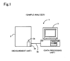
- Fig. 1 is a front view briefly showing the structure of the sample analyzer of an embodiment.
- a sample analyzer 1 of the present embodiment is used in blood testings, comprises a measurement unit 2 and data processing unit 3.
- the measurement unit 2 performs predetermined measurements of components contained in blood specimens, and the measurement data are subjected to an analysis process when received by the data processing unit 3.
- the sample analyzer 1 is installed in medical facilities such as hospitals, or pathology laboratories and the like.
- the measurement unit 2 and data processing unit 3 are connected by a data transfer cable 3a so as to be capable of mutual data communications.
- the configuration is not limited to a direct connection between the measurement unit 1 and data processing unit 3 by the data transfer cable 3a, inasmuch as, for example, the measurement unit 2 and data processing unit 3 may also be connected through a dedicated line using a telephone line, or a communication network such as a LAN, Internet or the like.
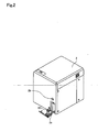
- Fig. 2 is a perspective view of the exterior of the measurement unit 2.
- a blood collection tube placement unit 2a for placing a blood collection tube 20 that contains a blood sample.
- the blood collection tube placement unit 2a can receive a blood collection tube 20 placed therein by a user when a button switch 2b provided nearby is pressed by the user and the blood collection tube placement unit 2a moves in a forward direction. After the blood collection tube 20 has been placed, the user again presses the button switch 2b and the blood collection tube placement unit 2a withdraws and closes.
- Fig. 3 is a perspective view showing the interior structure of the measurement unit 2
- Fig. 4 is a side view of the same.
- the blood collection tube placement unit 2a holding the collection tube 20 is received within the measurement unit 2 as previously described, and the collection tube 20 is positioned at a predetermined suction position.
- a sample supply unit 4 including a pipette 21 for suctioning samples, chambers 22 and 23 for mixing and adjusting blood and reagent and the like is provided within the measurement unit 2.
- the pipette 21 is tube-like and extends vertically, and the tip is sharply tapered.
- the pipette 21 is linked to a syringe pump not shown in the drawing, and a predetermined amount of liquid can be suctioned or discharged by the operation of this syringe pump; the pipette 21 is also linked to a moving mechanism so as to be movable in vertical directions and forward and backward directions.
- the blood collection tube 20 is sealed by a rubber cap 20a, and the sharp tip of the pipette 21 pieces the cap 20a of the collection tube 20 placed at the suction position, and a predetermined amount of blood sample contained in the collection tube 20 can be suctioned by the pipette 21. As shown in Fig.
- chambers 22 and 23 are provided behind the collection tube placement unit 2a; the pipette 21 is moved by the moving mechanism when the blood sample has been suctioned, and supplies the blood sample to the chambers 22 and 23 by discharging the blood sample into the chambers 22 and 23.
- Fig. 5 is a block diagram showing the structure of the measurement unit 2
- Fig. 6 is a flow circuit diagram showing the structure of the sample supply unit 4.
- the measurement unit 2 is provided with a sample supply unit 4, WBC detection unit 5, RBC detection unit 6, HGB detection unit 7, control unit 8, and communication unit 9.
- the control unit 8 is configured by a CPU, ROM, RAM and the like, and performs operation control of each type of structural element of the measurement unit 2.
- the communication unit 9 is an interface, such as, for example, an RS-232C interface, USB interface, Ethernet (registered trademark), and is capable of sending and receiving data to/from the data processing unit 3.
- the sample supply unit 4 is a flow unit provided with a plurality of electromagnetic valves, diaphragm pumps and the like.
- Chamber 22 is used to prepare the sample supplied for the measurement of red blood cells and platelets, and the measurement of hemoglobin.
- the chamber 23 is used to prepare the sample supplied for white blood cell measurement.
- Fig. 6 shows only the structure of the flow circuit on the periphery of the chamber 23 in order to simplify the drawing.
- the chamber 23 is connected to a reagent container FFD accommodating hemolytic agent and a reagent container FFS accommodating staining fluid through fluid flow paths P1 and P2, such as tubes or the like.
- Electromagnetic valves SV19 and SV20 are provided in the fluid flow path P1 connecting the chamber 23 and the reagent container FFD, and a diaphragm pump DP4 is provided between the electromagnetic valves SV19 and SV20.
- the diaphragm pump DP4 is connected to a positive pressure source and a negative pressure source, such that the diaphragm pump DP4 can be operated by positive pressure drive and negative pressure drive.
- Electromagnetic valves SV40 and SV41 are provided in the fluid flow path P2 connecting the chamber 23 and the reagent container FFS, and a diaphragm pump DP5 is provided between the electromagnetic valves SV40 and SV41.
- the electromagnetic valves SV19, SV20, SV40, SV41, and diaphragm pumps DP4 and DP5 are operationally controlled as follows, and are capable of supplying hemolytic agent and staining fluid to the chamber 23.
- the electromagnetic valve SV19, which is disposed on the reagent container FFD side of the diaphragm pump DP4 is opened, and with the electromagnetic valve SV20, which is disposed on the chamber 23 side of the diaphragm pump DP4, in the closed state, a hemolytic agent is supplied in a fixed dosage from the reagent container FFD by negative pressure actuation of the diaphragm pump DP4.
- the electromagnetic valve SV19 is closed, the electromagnetic valve SV20 is opened, and the fixed quantity of hemolytic agent is supplied to the chamber 23 by positive pressure actuation of the diaphragm pump DP4.
- the electromagnetic valve SV40 which is disposed on the reagent container FFS side of the diaphragm pump DP5
- the electromagnetic valve SV41 which is disposed on the chamber 23 side of the diaphragm pump DP5
- a staining fluid is supplied in a fixed dosage from the reagent container FFS by negative pressure actuation of the diaphragm pump DP5.
- the electromagnetic valve SV40 is closed, the electromagnetic valve SV41 is opened, and the fixed quantity of staining fluid is supplied to the chamber 23 by positive pressure actuation of the diaphragm pump DP5.
- the blood sample and reagents hemolytic reagent and staining fluid
- the sample is prepared for white blood cell measurement.
- the chamber 23 is connected to the WBC detection unit flow cytometer through a fluid flow path P3 that includes tubes and an electromagnetic valve SV4.
- the fluid flow path P3 branches in its medial region, and electromagnetic valves SV1 and SV3 are connected in series at the branch.
- a syringe pump SP2 is disposed medially to the electromagnetic valves SV1 and SV3.
- a stepping motor M2 is connected to the syringe pump SP2, such that the syringe pump SP2 is actuated by the operation of the stepping motor M2.
- the fluid flow path P3 connecting the chamber 23 and the WBC detection unit 5 also branches, and an electromagnetic valve SV29 and diaphragm pump DP6 are connected at the branch.
- the diaphragm pump DP6 When white blood cells are measured by the WBC detection unit 5, the diaphragm pump DP6 is operated under negative pressure with the electromagnetic valves SV4 and SV29 in an open state, and the sample charges the fluid flow path P3 when the sample is suctioned from the chamber 23. When the sample charging is completed, the electromagnetic valves SV4 and SV29 are closed. Thereafter, the electromagnetic valve SV3 is opened, and the charged sample is supplied to the WBC detection unit 5 by operating the syringe pump SP2.
- the sample supply unit 4 is provided with a sheath fluid chamber 24, and the sheath fluid chamber 24 is connected to the WBC detection unit 5 through the fluid flow path P4.
- An electromagnetic valve SV31 is provided in the fluid flow path P4.
- the sheath fluid chamber 24 is a chamber for storing sheath fluid to be supplied to the WBC detection unit 5, and is connected to the sheath fluid container EPK that holds the sheath fluid through the fluid flow path P5 that includes tubes and an electromagnetic valve SV33.
- the electromagnetic valve SV33 is opened and sheath fluid is supplied to the sheath fluid chamber 24, such that sheath fluid is stored in the sheath fluid chamber 24 beforehand.
- the electromagnetic valve SV31 is opened, and sheath fluid stored in the sheath fluid chamber 24 is supplied to the WBC detection unit 5 simultaneously with the sample supplied to the WBC detection unit 5.
- the WBC detection unit 5 is an optical type flow cytometer, and is capable of measuring white blood cells by a flow cytometry via a semiconductor laser.
- the WBC detection unit 5 is provided with a flow cell 51, which forms the fluid flow of the sample.
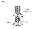
- Fig. 7 is a perspective view schematically showing the structure of the flow cell 51.
- the flow cell 51 is configured by a material such as transparent glass, glass, synthetic resin and the like, formed in a tube-like shape, and is a flow path through the interior of which the sheath fluid flows.
- the flow cell 51 is provided with an orifice 51a, the internal cavity of which has an aperture that is narrower than the other parts.
- the vicinity of the inlet of the orifice 51a of the flow cell 51 has a double-tube structure, and the internal side of this tube part becomes a sample nozzle 51b.
- the sample nozzle 51b is connected to the fluid flow path P3 of the sample supply unit 4, and sample is discharged through the sample nozzle 51b.
- the cavity on the outer side of the sample nozzle 51b is the flow path 51c through which the sheath fluid flows, and the flow path 51c is connected to the previously described fluid flow path P4.
- the sheath fluid supplied from the sheath fluid chamber 24 flows through the flow path 51c via the fluid flow path P4, and is introduced to the orifice 51a.
- the sheath fluid supplied to the flow cell 51 in this way flows so as to encapsulate the sample discharged from the sample nozzle 51b. Then, the sample flow is constricted by the orifice 51a, such that the particles of white blood cells and red blood cells contained in the sample are encapsulated in the sheath fluid and pass through the orifice 51a one by one.
- Fig. 8 is a brief plan view that schematically shows the structure of the WBC detection unit 5.
- a semiconductor laser light source 52 is arranged in the WBC detection unit 5 so as to emit laser light toward the flow cell 51.
- An illumination lens system 53 including a plurality of lenses is arranged medially to the flow cell 51 and the semiconductor laser light source 52. Parallel beams emitted from the semiconductor laser light source 52 are collected at a beam spot by the illumination lens system 53.
- a beam stopper 54a is provided on the optical axis extending linearly from the semiconductor laser light source 52 so as to be opposite the illumination lens system 53 and with the flow cell 51 interposed therebetween.
- a photodiode 54 is arranged on the optical axis downstream of the beam stopper 54a.
- optical signals of scattered light and fluorescent light are generated by the laser light.
- the forward scattered light signals irradiate toward the photodiode 54.
- the direct light of the semiconductor laser 52 is blocked by the beam stopper 54a, and only the scattered light (hereinafter referred to as "forward scattered light") advancing along the optical axis direction enters the photodiode 54.
- the forward scattered light emitted from the flow cell 51 is subjected to photoelectric conversion by the photodiode 54, and the electrical signals (hereinafter referred to as "forward scattered light signals") generated by this conversion are amplified by an amplifier 54b, and output to the control unit 8.
- the forward scattered light signals reflect the size of the blood cells, and the size of the blood cells and the like can be obtained when the control unit 8 subjects the forward scattered light signals to signal processing.
- a side collective lens 55 is arranged at the side of the flow cell 51, in a direction perpendicular to the optical axis extending linearly from the semiconductor laser light source 52 to the photodiode 54, and the lateral light (light emitted in a direction intersecting the optical axis) generated when the semiconductor laser irradiates the blood cells passing through the flow cell 51 is collected by the side collective lens 55.
- a dichroic mirror 56 is provided on the downstream side of the side collective lens 55, and the signal light transmitted from the side collective lens 55 is divided into a scattered light component and fluorescent light component by the dichroic mirror 56.
- a side scattered light photoreceptor photodiode 57 is provided at the side (the direction intersecting the direction of the optical axis connecting the side collective lens 55 and the dichroic mirror 56) of the dichroic mirror 56, and an optical filter 58a and avalanche photodiode 58 are provided on the optical axis on the downstream side of the dichroic mirror 56. Then, the side scattered light component separated by the dichroic mirror 56 is subjected to photoelectric conversion by the photodiode 57, and the electrical signals (hereinafter referred to as "side scattered light signals”) generated by this conversion are amplified by an amplifier 57a and output to the control unit 8.
- the side scattered light signals reflect the internal information (size of the nucleus and the like) of the blood cells, and the size of the nucleus of the blood cell and the like can be obtained when the control unit 8 subjects the side scattered light signal to signal processing. Furthermore, the side fluorescent light component emitted from the dichroic mirror 56 is subjected to wavelength selection by the optical filter 58a, and subsequent photoelectric conversion by the avalanche photodiode 58, and the electrical signals (side fluorescent light signals) thus obtained are amplified by an amplifier 58b and output to the control unit 8.
- the side fluorescent light signals reflect information related to the degree of staining of the blood cells, and the stainability of the blood cells can be obtained by subjecting the side fluorescent light signals to signal processing.
- the RBC detection unit 6 can measure the number of red blood cells and platelets by a sheath flow DC detection method.
- the RBC detection unit 6 has a flow cell, and sample is supplied from the previously mentioned chamber 22 to the flow cell.
- a sample is prepared by mixing solution fluid with the blood in the chamber 22.
- the sample is supplied from the sample supply unit to the flow cell together with the sheath fluid, and a flow is formed in which the sample is encapsulated in the sheath fluid within the flow cell.
- an aperture with an electrode is provided in the flow path in the flow cell, and the direct current (DC) resistance in the aperture is detected when the blood cells in the sample pass thought the aperture one by one, and the electrical signal of the DC resistance is output to the control unit 8. since the DC resistance increases when the blood cell passes through the aperture, the electrical signal reflects information of the passage of the blood cell through the aperture, and the red blood cells and platelets can be counted by subjecting the electrical signals to signal processing.
- the HGB detection unit 7 is capable of measuring the amount of hemoglobin by the SLS hemoglobin method.
- the HGB detection unit 7 is provided with a cell for accommodating dilute sample, sample is supplied from the chamber 22 to this cell.
- a sample is prepared by mixing dilution liquid and hemolytic reagent in blood in the chamber 22.
- the hemolytic reagent has the characteristic of transforming hemoglobin in the blood to SLS hemoglobin.
- a light-emitting diode and photodiode are arranged in opposition with the cell interposed therebetween, and light emitted from the light-emitting diode is received by the photodiode.
- the light-emitting diode emits light of a wavelength that has high absorption by SLS hemoglobin, and the cell is formed of a plastic material of high transparency.
- the photodiode outputs electrical signals corresponding to the amount of received light (optical density) to the control unit 8, and the control unit 8 compares this optical density with the optical density of the dilution liquid alone which was measured beforehand, then calculates the hemoglobin value.
- the control unit 8 receives electrical signals from the WBC detection unit 5, the RBC detection unit 6, and the HGB detection unit 7, and obtains the measurement data indicating the size of the blood cells, the size of the nucleus of the blood cells, the stainability of the blood cells, the number of red blood cells, the number of blood platelets, the hemoglobin value and the like. As shown in Fig.
- control unit 8 includes a signal processing circuit 8a and a control circuit 8b, where the output signal (side fluorescent light signal, forward scattered light signal, side scattered light signal) of the WBC detection unit 5, the output signal of the RBC detection unit 6, and the output signal of the HGB detection unit 7 are respectively signal processed by the signal processing circuit 8a to acquire the measurement data, and the measurement data is transmitted to the data processing unit 3 by the control circuit 8b.
- the data processing unit 3 is configured by a computer provided with a CPU, ROM, RAM, hard disk, communication interface, input unit including a keyboard and mouse and the like, and a display device.
- the communication interface is, for example, an RS-232C interface, USB interface, Ethernet (registered trademark), and is capable of sending and receiving data to/from the measurement unit 2.
- an operating system, and application program for analyzing the measurement data received from the measurement unit 2 are installed on the hard disk of the data processing unit 3.
- WBC white blood cell count
- RBC red blood cell count
- HGB hemoglobin amount
- HCT hematocrit value
- MCV mean red blood cell volume
- MH mean red blood cell hemoglobin
- MCHC mean red blood cell hemoglobin concentration
- PHT platelet count
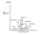
- Fig. 9 is a scattergram prepared using the blood analyzer according to the present embodiment.
- the vertical axis shows the intensity of the side fluorescent light (level of received light), and the horizontal axis shows the intensity of the side scattered light (level of received light).
- measurement is performed using the same normal blood sample.
- the blood analyzer 1 according to the present embodiment has a configuration of classifying the white blood cells into five classification of neutrophils, lymphocytes, monocytes, eosinophils, and basophils all at once, where each cluster of neutrophils, lymphocytes, monocytes, eosinophils, and basophils is clearly formed in the scattergram prepared by the blood analyzer 1, as shown in Fig. 9, indicating that the white blood cells are classified at high precision.
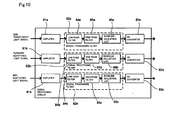
- Fig. 10 is a block diagram showing a schematic configuration of the signal processing circuit 8a shown in Fig. 5.
- the signal processing circuit 8a includes amplifiers 81a to 81c, signal processing filters 82a to 82c, and AD converters 83a to 83c.
- the signal processing filters 82a to 82c respectively includes low pass filters (high cut filters) 84a to 84c for reducing the high frequency noise, high pass filters 85a to 85c for reducing the fluctuation at the baseline of the signal, and baseline adjusting units 86a to 86c for adjusting the baseline of the signal to a predetermined level.
- the side fluorescent light signal output from the WBC detection unit 5 is processed by the amplifier 81a, the signal processing filter 82a, and the AD converter 83a; the forward fluorescent light signal output from the WBC detection unit 5 is processed by the amplifier 81b, the signal processing filter 82b, and the AD converter 83b; and the side scattered light signal output from the WBC detection unit 5 is processed by the amplifier 81c, the signal processing filter 82c, and the AD converter 83c.
- Only the circuits for processing the output signals from the WBC detection unit 5 are shown in Fig. 10 to simplify the explanation, but circuits for processing the output signals of the RBC detection unit 6 and the HGB detection unit are also arranged in the signal processing circuit 8a.
- the set value of gain of the amplifiers 81a to 81c is switched by the measurement mode (white blood cell classifying mode, reticular red blood cell measurement mode etc.)
- the gain adjustment is performed by adjusting the gain so that the standard particles appear at the appropriate appearing position when the standard particles (e.g., control blood, calibrator), whose appearing position on the scattergram is known in advance in an appropriately gain adjusted state, are being measured.
- the low pass filters 84a to 84c are set with an appropriate high pass cut-off frequency so as to efficiently attenuate the noise of the side fluorescent light signal, the forward scattered light signal, and the side scattered light signal.
- the high pass cut-off frequency of the low pass filter 84a is set to less than or equal to the frequency Y obtained by equation (5).
- Y 10.482 ⁇ EXP ⁇ - 0.018 ⁇ C + 1.3
- C inter-terminal capacity of avalanche photodiode
- Fig. 11 is a frame format view explaining the range used in the analysis of the amplified signal of the side fluorescent light signal.
- the full scale input voltage of the AD converter 83a is 4V, and the resolution is 8 bits in the blood analyzer 1 according to the present embodiment.
- Figs. 12 to 21 are scattergrams obtained for when the maximum allowable level is 80mV-p, 100mVp-p, 150mVp-p, 200mVp-p, 250mVp-p, 300mVp-p, 400mVp-p, 500mVp-p, 600mVp-p and 700mVp-p. In Figs.
- the regions enclosed with a solid line respectively show the respective regions in which neutrophils, lymphocytes, monocytes, eosinophils, and basophils are present.
- the level of noise is 300mVp-p
- the overlap of the regions in which neutrophils, lymphocytes, monocytes, eosinophils, and basophils are present is small, and the white blood cells can be satisfactorily classified into five classifications with the noise level of such extent.
- the region in which the lymphocytes are present overlaps the region in which the ghosts are present, as shown in Figs. 20 and 21, when the maximum allowable level of noise is greater than or equal to 600mVp-p, but the region in which the lymphocytes are present and the region in which the ghosts are present do not overlap for 500mVp-p, as shown in Fig. 19.
- the position at which the lymphocytes are present and the position at which the ghosts are present do not overlap and can be satisfactorily discriminated when the maximum allowable noise level is less than or equal to 500mVp-p, and the white blood cells can be satisfactorily classified as a result.
- the number of basophils is usually less than or equal to 1% of the entire white blood cells, and thus the fractionation of the basophils may not be performed since it is sufficiently practicable if the white blood cells can be classified into four classifications of neutrophils, lymphocytes, monocytes, and eosinophils.
- the white blood cells may be classified into four classifications, the basophils may be independently measured, and the results may be combined to have five classifications.
- the avalanche photodiode has a property in that the inter-terminal capacity becomes larger and the S/N ratio of the output signal becomes lower as the light receiving surface becomes larger. Therefore, the noise component contained in the side fluorescent light signal increases as the light receiving surface of the avalanche photodiode becomes larger, whereby the high pass cut-off frequency of the low pass filter 84a must be set low. In other words, the high pass cut-off frequency corresponding to the maximum allowable level of the same noise changes according to the inter-terminal capacity of the avalanche photodiode.
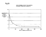
- Figs. 22 and 23 are graphs showing the relationship between the inter-terminal capacity of the avalanche photodiode and the high pass cut-off frequency of the low pass filter 84a of when the maximum allowable level of the noise is 300mVp-p and 500mVp-p, respectively.
- the high pass cut-off frequency corresponding to the maximum allowable level of the noise of 300mVp-p when the inter-terminal capacity is 0pF was 10.28MHz, as shown in Fig. 22.
- the maximum allowable level of the noise is 300mVp-p
- the inter-terminal capacity is 1pF, 3pF, 5pF, 10pF, 18pF, 36pF, 56pF, 120pF, 240pF, and 470pF
- the respective high pass cut-off frequency was 10.11MHz, 9.6MHz, 9.14MHz, 7.97MHz, 6.62MHz, 5.19MHz, 4.18MHz, 2.22MHz, 1.55MHz, 1.35MHz, and 0.87MHz.
- the approximate expression of the relationship between the inter-terminal capacity and the limiting frequency of when the maximum allowable level of the noise is 300mVp-p is as expressed with equation (5). In Fig. 22, the curve of equation (5) is shown with a solid line.
- the maximum allowable level of the noise is set to 500mVp-p
- the inter-terminal capacity is 0pF, 1pF, 3pF, 5pF, 10pF, 18pF, 36pF, 56pF, 120pF, 240pF, and 470pF
- the respective high pass cut-off frequency was 18.86MHz, 18.62MHz, 16.94MHz, 16.35MHz, 13.47MHz, 10.48MHz, 8.09MHz, 6.32MHz, 3.46MHz, 2.47MHz, 2.18MHz, and 1.52MHz, as shown in Fig. 23.
- the approximate expression of the relationship between the inter-terminal capacity and the limiting frequency of when the maximum allowable level of the noise is 500mVp-p is as expressed with equation (6).
- the curve of equation (6) is shown with a solid line.
- Y 17.289 ⁇ EXP ⁇ - 0.022 ⁇ C + 2 C: inter-terminal capacity of avalanche photodiode
- the high pass cut-off frequency is set to lower than or equal to the frequency Y provided by equation (5) and the noise level contained in the signal after the noise reduction by the low pass filter 84a is set to less than or equal to 300mVp-p in the present embodiment, but are not limited thereto, and the high pass cut-off frequency may be set to less than or equal to the frequency Y provided by equation (6), and the noise level to lower than or equal to 500mVp-p, in which case, a satisfactory analysis result is also obtained.
- the noise level is set to lower than or equal to 500mVp-p.
- the noise contained in the output signal can be further reduced by having a smaller inter-terminal capacity of the avalanche photodiode 58.
- the S/N ratio is enhanced by enhancing the intensity of the light emitted from the semiconductor laser light source 52, but such effect is low compared to when the light receiving surface (i.e., inter-terminal capacity) of the avalanche photodiode 58 is made small, and is also not preferable in terms of power consumption since the energy consumption increases when the level of the output light is increased. It is essential to have the light receiving surface of the avalanche photodiode 58 as small as possible.
- the light receiving surface may become smaller than the image of the particles projected onto the light receiving surface of the avalanche photodiode 58 by the side light collective lens 55 if the light receiving surface of the avalanche photodiode 58 is made small in excess, and the side fluorescent light signal accurately reflecting the information related to the particles may not be obtained.
- the image of the particles may be made smaller than the light receiving surface by reducing the magnification of the side light collective lens 55.
- the light receiving surface is too small, the positional adjustment with the optical axis becomes difficult and high precision in assembly becomes necessary, which leads to increase in the manufacturing cost.
- the avalanche photodiode 58 having a circular light receiving surface of a diameter of 1.5 mm is used in the present invention taking into consideration the noise level of the output signal of the avalanche photodiode, the manufacturing cost of the optical lens, the precision in assembly of the WBC detection unit 5 and the like.
- the inter-terminal capacity of the avalanche photodiode 58 was 8.4 pF.
- the high pass cut-off frequency of the low pass filter 84a was 2.3 MHz in the present embodiment.
- the shape of the light receiving surface of the avalanche photodiode 58 is circular with a diameter of 1.5 mm in the present embodiment, the shape is not limited thereto, and may be a circular shape with a diameter of 0.1 mm-2 mm, may be a square with a side length of 0.1-2 mm, or may be other shapes such as a rectangular shape having a surface area of the same degree.
- the measurement unit 2 and the data processing unit 3 are separately arranged, the blood analyzer 1 is configured by such units in the present embodiment, but configuration of the blood analyzer 1 is not limited thereto, and an integrated blood analyzer having both the function of the measurement unit 2 and the function of the data processing unit 3 may be provided.
Abstract
Description
- The present invention relates to a blood analyzer and method for analyzing blood sample.
- A blood analyzer, which includes an optical flow cytometer, for analyzing a blood sample is known. The flow cytometer is provided with a flow cell for conducting the liquid of the blood sample, a light source for irradiating light onto the flow cell, and a light receiving element, and the light irradiated from the light source is scattered by the particles in the flow cell. The hemolyzing process of the red blood cells and the staining process of the particles of the white blood cells and the like are performed by adding hemolytic agent and fluorescence reagent to the blood sample, and the stained particles emit fluorescence light when receiving light. The scattered light and the fluorescence light are received by the light receiving elements, and the detection signals thereof are analyzed to measure the white blood cells in the blood sample and to classify the white blood cells to lymphocytes, monocytes, granulocytes and the like. In such flow cytometer, since the classification of the white blood cells and the ghosts (red blood cell membrane not completely shrunk with hemolytic agent) is discriminated using the fluorescent light signal, the hemolytic agent having high hemolyzing ability of shrinking the red blood cells to an extent the sizes of the white blood cells and the ghost can be clearly distinguished does not need to be used and thus the extent of damage of the white blood cells is alleviated and the form of the white blood cells is maintained. The reagent for dissolving the red blood cells while maintaining the form of the white blood cells to have the blood sample in a state suitable for the classification of the white blood cells has been disclosed (see
US Patent No. 6,004,816 ). - Furthermore, an optical system of high measurement accuracy becomes necessary since the classification of the white blood cells by means of the flow cytometer is performed based on the slight difference in size and form of the cell or the nucleus of each white blood cell. Moreover, the optical system of high measurement accuracy is necessary to discriminate the white blood cells and the ghosts using the fluorescent light signal since some ghosts are attached with a small amount of fluorescent pigment and thus emit fluorescent light signal. A photo-multiplier (photoelectron multiplier) having high sensitivity is generally used as the fluorescent light receiving element (see e.g.,
US Patent No. 6,365,106 ). Furthermore, a flow cytometer using an avalanche photodiode (APD) as the light receiving element for receiving fluorescent light is also disclosed (seeUS patent No. 5,739,902 ). - The amplification ratio of the signal of the element itself is low in the avalanche photodiode compared to the photo-multiplier, and thus the gain of the amplifying circuit arranged in the post-stage of the element must be set large. However, if the output signal of the avalanche photodiode is amplified with the amplifying circuit set with a large gain, the level of high frequency noise generated in the amplifying circuit increases, and high precision analysis of the sample becomes difficult.
- The scope of the present invention is defined solely by the appended claims, and is not affected to any degree by the statements within this summary.
- A first aspect of the present invention is a blood analyzer, comprising: a sample preparing part for preparing a measurement sample comprising a blood, a hemolyzing reagent, and a staining reagent; a flow cell in which the measurement sample flows; a light source for irradiating the measurement sample flowing in the flow cell; a scattered light detector for detecting scattered light from the measurement sample irradiated by the light source; a fluorescence light detector comprising an avalanche photo diode for detecting fluorescence light from the measurement sample irradiated by the light source; a signal processing part for processing a first detection signal from the scattered light detector and a second detection signal from the fluorescence light detector, wherein the signal processing part reduces high frequency noise included in an amplified second detection signal; and a analysis part for classifying white blood cells in the blood into groups based on the first and the second detection signals processed by the signal processing part.
A second aspect of the present invention is a blood analyzer, comprising: a sample preparing part for preparing a measurement sample comprising a blood, a hemolyzing reagent, and a staining reagent; a flow cell in which the measurement sample flows; a light source for irradiating the measurement sample flowing in the flow cell; a scattered light detector for detecting scattered light from the measurement sample irradiated by the light source; a fluorescence light detector comprising an avalanche photo diode for detecting fluorescence light from the measurement sample irradiated by the light source; a signal processing part for processing a first detection signal from the scattered light detector and a second detection signal from the fluorescence light detector, wherein the signal processing part comprises a low pass filter for reducing high frequency noise included in an amplified second detection signal; and a analysis part for classifying white blood cells in the blood into groups based on the first and the second detection signals processed by the signal processing part; wherein a cutoff frequency of the low pass filter is less than frequency Y of following formula:
(C represents electric capacity between terminals of the avalanche photo diode).
A third aspect of the present invention is a blood analyzing method, comprising: preparing a measurement sample comprising a blood, a hemolyzing reagent, and a staining reagent; exposing the measurement sample to light from a light source; detecting scattered light from the measurement sample irradiated by the light source; detecting, by an avalanche photo diode, fluorescence light from the measurement sample irradiated by the light source; processing a first detection signal obtained from the scattered light; processing a second detection signal obtained from the fluorescence light, the processing of the second detection signal comprising reducing high frequency noise included in an amplified second detection signal; and classifying white blood cells in the blood into groups based on a processed first detection signal and a processed second detection signal. - The invention, together with objects and advantages thereof, may best be understood by reference to the following description of the presently preferred embodiments together with the accompanying drawings in which:
- Fig. 1 is a front view briefly showing the structure of the sample analyzer of an embodiment;
- Fig. 2 is a perspective exterior view of the measurement unit provided in the sample analyzer of the embodiment;
- Fig. 3 is a perspective view showing the internal structure of the measurement unit provided in the sample analyzer of the embodiment;
- Fig. 4 is a side view showing the internal structure of the measurement unit provided in the sample analyzer of the embodiment;
- Fig. 5 is a block diagram showing the structure of the measurement unit provided in the sample analyzer of the embodiment;
- Fig. 6 is a fluid circuit diagram showing the structure of the sample supply section provided in the measurement unit;
- Fig. 7 is a perspective view schematically showing the structure of the flow cell provided in the measurement unit;
- Fig. 8 is a brief plan view schematically showing the structure of the flow cytometer provided in the measurement unit;
- Fig. 9 is a scattergram prepared using the blood analyzer according to the embodiment;
- Fig. 10 is a block diagram showing a schematic configuration of the signal processing circuit shown in Fig. 5;
- Fig. 11 is a frame format view explaining the range used in the analysis of the amplified signal of the side fluorescent light signal;
- Fig. 12 is a scattergram obtained when the maximum allowable level of noise is set to 80mVp-p;
- Fig. 13 is a scattergram obtained when the maximum allowable level of noise is set to 100mVp-p;
- Fig. 14 is a scattergram obtained when the maximum allowable level of noise is set to 150mVp-p;
- Fig. 15 is a scattergram obtained when the maximum allowable level of noise is set to 200mVp-p;
- Fig. 16 is a scattergram obtained when the maximum allowable level of noise is set to 250mVp-p;
- Fig. 17 is a scattergram obtained when the maximum allowable level of noise is set to 300mVp-p;
- Fig. 18 is a scattergram obtained when the maximum allowable level of noise is set to 400mVp-p;
- Fig. 19 is a scattergram obtained when the maximum allowable level of noise is set to 500mVp-p;
- Fig. 20 is a scattergram obtained when the maximum allowable level of noise is set to 600mVp-p;
- Fig. 21 is a scattergram obtained when the maximum allowable level of noise is set to 700mVp-p;
- Fig. 22 is a graph showing the relationship between the inter-terminal capacity of the avalanche photodiode and the high pass cut-off frequency of the A/D converter when the maximum allowable level of noise is set to 300mVp-p; and
- Fig. 23 is a graph showing the relationship between the inter-terminal capacity of the avalanche photodiode and the high pass cut-off frequency of the A/D converter when the maximum allowable level of noise is set to 500mVp-p.
- The preferred embodiments of the present invention are described hereinafter with reference to the drawings.
- Fig. 1 is a front view briefly showing the structure of the sample analyzer of an embodiment. As shown in Fig. 1, a
sample analyzer 1 of the present embodiment is used in blood testings, comprises ameasurement unit 2 anddata processing unit 3. Themeasurement unit 2 performs predetermined measurements of components contained in blood specimens, and the measurement data are subjected to an analysis process when received by thedata processing unit 3. Thesample analyzer 1 is installed in medical facilities such as hospitals, or pathology laboratories and the like. Themeasurement unit 2 anddata processing unit 3 are connected by adata transfer cable 3a so as to be capable of mutual data communications. The configuration is not limited to a direct connection between themeasurement unit 1 anddata processing unit 3 by thedata transfer cable 3a, inasmuch as, for example, themeasurement unit 2 anddata processing unit 3 may also be connected through a dedicated line using a telephone line, or a communication network such as a LAN, Internet or the like. - Fig. 2 is a perspective view of the exterior of the
measurement unit 2. As shown in Fig. 2, at the lower right of the front of themeasurement unit 2, is provided with a blood collectiontube placement unit 2a for placing ablood collection tube 20 that contains a blood sample. The blood collectiontube placement unit 2a can receive ablood collection tube 20 placed therein by a user when abutton switch 2b provided nearby is pressed by the user and the blood collectiontube placement unit 2a moves in a forward direction. After theblood collection tube 20 has been placed, the user again presses thebutton switch 2b and the blood collectiontube placement unit 2a withdraws and closes. - Fig. 3 is a perspective view showing the interior structure of the
measurement unit 2, and Fig. 4 is a side view of the same. The blood collectiontube placement unit 2a holding thecollection tube 20 is received within themeasurement unit 2 as previously described, and thecollection tube 20 is positioned at a predetermined suction position. Asample supply unit 4 including apipette 21 for suctioning samples,chambers measurement unit 2. Thepipette 21 is tube-like and extends vertically, and the tip is sharply tapered. Thepipette 21 is linked to a syringe pump not shown in the drawing, and a predetermined amount of liquid can be suctioned or discharged by the operation of this syringe pump; thepipette 21 is also linked to a moving mechanism so as to be movable in vertical directions and forward and backward directions. Theblood collection tube 20 is sealed by arubber cap 20a, and the sharp tip of thepipette 21 pieces thecap 20a of thecollection tube 20 placed at the suction position, and a predetermined amount of blood sample contained in thecollection tube 20 can be suctioned by thepipette 21. As shown in Fig. 4,chambers tube placement unit 2a; thepipette 21 is moved by the moving mechanism when the blood sample has been suctioned, and supplies the blood sample to thechambers chambers - Fig. 5 is a block diagram showing the structure of the
measurement unit 2, and Fig. 6 is a flow circuit diagram showing the structure of thesample supply unit 4. As shown in Fig. 4, themeasurement unit 2 is provided with asample supply unit 4,WBC detection unit 5,RBC detection unit 6,HGB detection unit 7,control unit 8, andcommunication unit 9. Thecontrol unit 8 is configured by a CPU, ROM, RAM and the like, and performs operation control of each type of structural element of themeasurement unit 2. Thecommunication unit 9 is an interface, such as, for example, an RS-232C interface, USB interface, Ethernet (registered trademark), and is capable of sending and receiving data to/from thedata processing unit 3. - As shown in Fig. 6, the
sample supply unit 4 is a flow unit provided with a plurality of electromagnetic valves, diaphragm pumps and the like.Chamber 22 is used to prepare the sample supplied for the measurement of red blood cells and platelets, and the measurement of hemoglobin. Thechamber 23 is used to prepare the sample supplied for white blood cell measurement. Fig. 6 shows only the structure of the flow circuit on the periphery of thechamber 23 in order to simplify the drawing. Thechamber 23 is connected to a reagent container FFD accommodating hemolytic agent and a reagent container FFS accommodating staining fluid through fluid flow paths P1 and P2, such as tubes or the like. Electromagnetic valves SV19 and SV20 are provided in the fluid flow path P1 connecting thechamber 23 and the reagent container FFD, and a diaphragm pump DP4 is provided between the electromagnetic valves SV19 and SV20. The diaphragm pump DP4 is connected to a positive pressure source and a negative pressure source, such that the diaphragm pump DP4 can be operated by positive pressure drive and negative pressure drive. Electromagnetic valves SV40 and SV41 are provided in the fluid flow path P2 connecting thechamber 23 and the reagent container FFS, and a diaphragm pump DP5 is provided between the electromagnetic valves SV40 and SV41. - The electromagnetic valves SV19, SV20, SV40, SV41, and diaphragm pumps DP4 and DP5 are operationally controlled as follows, and are capable of supplying hemolytic agent and staining fluid to the
chamber 23. First, the electromagnetic valve SV19, which is disposed on the reagent container FFD side of the diaphragm pump DP4, is opened, and with the electromagnetic valve SV20, which is disposed on thechamber 23 side of the diaphragm pump DP4, in the closed state, a hemolytic agent is supplied in a fixed dosage from the reagent container FFD by negative pressure actuation of the diaphragm pump DP4. Thereafter, the electromagnetic valve SV19 is closed, the electromagnetic valve SV20 is opened, and the fixed quantity of hemolytic agent is supplied to thechamber 23 by positive pressure actuation of the diaphragm pump DP4. Similarly, the electromagnetic valve SV40, which is disposed on the reagent container FFS side of the diaphragm pump DP5, is opened, and with the electromagnetic valve SV41, which is disposed on thechamber 23 side of the diaphragm pump DP5, in the closed state, a staining fluid is supplied in a fixed dosage from the reagent container FFS by negative pressure actuation of the diaphragm pump DP5. Thereafter, the electromagnetic valve SV40 is closed, the electromagnetic valve SV41 is opened, and the fixed quantity of staining fluid is supplied to thechamber 23 by positive pressure actuation of the diaphragm pump DP5. Thus, the blood sample and reagents (hemolytic reagent and staining fluid) are mixed and the sample is prepared for white blood cell measurement. - Furthermore, the
chamber 23 is connected to the WBC detection unit flow cytometer through a fluid flow path P3 that includes tubes and an electromagnetic valve SV4. The fluid flow path P3 branches in its medial region, and electromagnetic valves SV1 and SV3 are connected in series at the branch. A syringe pump SP2 is disposed medially to the electromagnetic valves SV1 and SV3. A stepping motor M2 is connected to the syringe pump SP2, such that the syringe pump SP2 is actuated by the operation of the stepping motor M2. Furthermore, the fluid flow path P3 connecting thechamber 23 and theWBC detection unit 5 also branches, and an electromagnetic valve SV29 and diaphragm pump DP6 are connected at the branch. When white blood cells are measured by theWBC detection unit 5, the diaphragm pump DP6 is operated under negative pressure with the electromagnetic valves SV4 and SV29 in an open state, and the sample charges the fluid flow path P3 when the sample is suctioned from thechamber 23. When the sample charging is completed, the electromagnetic valves SV4 and SV29 are closed. Thereafter, the electromagnetic valve SV3 is opened, and the charged sample is supplied to theWBC detection unit 5 by operating the syringe pump SP2. - As shown in Fig. 6, the
sample supply unit 4 is provided with asheath fluid chamber 24, and thesheath fluid chamber 24 is connected to theWBC detection unit 5 through the fluid flow path P4. An electromagnetic valve SV31 is provided in the fluid flow path P4. Thesheath fluid chamber 24 is a chamber for storing sheath fluid to be supplied to theWBC detection unit 5, and is connected to the sheath fluid container EPK that holds the sheath fluid through the fluid flow path P5 that includes tubes and an electromagnetic valve SV33. Before starting the measurement of white blood cells, the electromagnetic valve SV33 is opened and sheath fluid is supplied to thesheath fluid chamber 24, such that sheath fluid is stored in thesheath fluid chamber 24 beforehand. Then, when the measurement of white blood cells begins, the electromagnetic valve SV31 is opened, and sheath fluid stored in thesheath fluid chamber 24 is supplied to theWBC detection unit 5 simultaneously with the sample supplied to theWBC detection unit 5. - The
WBC detection unit 5 is an optical type flow cytometer, and is capable of measuring white blood cells by a flow cytometry via a semiconductor laser. TheWBC detection unit 5 is provided with aflow cell 51, which forms the fluid flow of the sample. Fig. 7 is a perspective view schematically showing the structure of theflow cell 51. Theflow cell 51 is configured by a material such as transparent glass, glass, synthetic resin and the like, formed in a tube-like shape, and is a flow path through the interior of which the sheath fluid flows. Theflow cell 51 is provided with anorifice 51a, the internal cavity of which has an aperture that is narrower than the other parts. The vicinity of the inlet of theorifice 51a of theflow cell 51 has a double-tube structure, and the internal side of this tube part becomes asample nozzle 51b. Thesample nozzle 51b is connected to the fluid flow path P3 of thesample supply unit 4, and sample is discharged through thesample nozzle 51b. Furthermore, the cavity on the outer side of thesample nozzle 51b is theflow path 51c through which the sheath fluid flows, and theflow path 51c is connected to the previously described fluid flow path P4. The sheath fluid supplied from thesheath fluid chamber 24 flows through theflow path 51c via the fluid flow path P4, and is introduced to theorifice 51a. The sheath fluid supplied to theflow cell 51 in this way flows so as to encapsulate the sample discharged from thesample nozzle 51b. Then, the sample flow is constricted by theorifice 51a, such that the particles of white blood cells and red blood cells contained in the sample are encapsulated in the sheath fluid and pass through theorifice 51a one by one. - Fig. 8 is a brief plan view that schematically shows the structure of the
WBC detection unit 5. A semiconductorlaser light source 52 is arranged in theWBC detection unit 5 so as to emit laser light toward theflow cell 51. Anillumination lens system 53 including a plurality of lenses is arranged medially to theflow cell 51 and the semiconductorlaser light source 52. Parallel beams emitted from the semiconductorlaser light source 52 are collected at a beam spot by theillumination lens system 53. Furthermore, abeam stopper 54a is provided on the optical axis extending linearly from the semiconductorlaser light source 52 so as to be opposite theillumination lens system 53 and with theflow cell 51 interposed therebetween. Aphotodiode 54 is arranged on the optical axis downstream of thebeam stopper 54a. - When the sample flows through the
flow cell 51, optical signals of scattered light and fluorescent light are generated by the laser light. Among these, the forward scattered light signals irradiate toward thephotodiode 54. Among the light advancing along the optical axis extending linearly from thesemiconductor laser 52, the direct light of thesemiconductor laser 52 is blocked by thebeam stopper 54a, and only the scattered light (hereinafter referred to as "forward scattered light") advancing along the optical axis direction enters thephotodiode 54. The forward scattered light emitted from theflow cell 51 is subjected to photoelectric conversion by thephotodiode 54, and the electrical signals (hereinafter referred to as "forward scattered light signals") generated by this conversion are amplified by anamplifier 54b, and output to thecontrol unit 8. The forward scattered light signals reflect the size of the blood cells, and the size of the blood cells and the like can be obtained when thecontrol unit 8 subjects the forward scattered light signals to signal processing. - Furthermore, a side
collective lens 55 is arranged at the side of theflow cell 51, in a direction perpendicular to the optical axis extending linearly from the semiconductorlaser light source 52 to thephotodiode 54, and the lateral light (light emitted in a direction intersecting the optical axis) generated when the semiconductor laser irradiates the blood cells passing through theflow cell 51 is collected by the sidecollective lens 55. Adichroic mirror 56 is provided on the downstream side of the sidecollective lens 55, and the signal light transmitted from the sidecollective lens 55 is divided into a scattered light component and fluorescent light component by thedichroic mirror 56. A side scatteredlight photoreceptor photodiode 57 is provided at the side (the direction intersecting the direction of the optical axis connecting the sidecollective lens 55 and the dichroic mirror 56) of thedichroic mirror 56, and anoptical filter 58a andavalanche photodiode 58 are provided on the optical axis on the downstream side of thedichroic mirror 56. Then, the side scattered light component separated by thedichroic mirror 56 is subjected to photoelectric conversion by thephotodiode 57, and the electrical signals (hereinafter referred to as "side scattered light signals") generated by this conversion are amplified by anamplifier 57a and output to thecontrol unit 8. The side scattered light signals reflect the internal information (size of the nucleus and the like) of the blood cells, and the size of the nucleus of the blood cell and the like can be obtained when thecontrol unit 8 subjects the side scattered light signal to signal processing. Furthermore, the side fluorescent light component emitted from thedichroic mirror 56 is subjected to wavelength selection by theoptical filter 58a, and subsequent photoelectric conversion by theavalanche photodiode 58, and the electrical signals (side fluorescent light signals) thus obtained are amplified by anamplifier 58b and output to thecontrol unit 8. The side fluorescent light signals reflect information related to the degree of staining of the blood cells, and the stainability of the blood cells can be obtained by subjecting the side fluorescent light signals to signal processing. - The
RBC detection unit 6 can measure the number of red blood cells and platelets by a sheath flow DC detection method. TheRBC detection unit 6 has a flow cell, and sample is supplied from the previously mentionedchamber 22 to the flow cell. When measuring red blood cells and platelets, a sample is prepared by mixing solution fluid with the blood in thechamber 22. The sample is supplied from the sample supply unit to the flow cell together with the sheath fluid, and a flow is formed in which the sample is encapsulated in the sheath fluid within the flow cell. Furthermore, an aperture with an electrode is provided in the flow path in the flow cell, and the direct current (DC) resistance in the aperture is detected when the blood cells in the sample pass thought the aperture one by one, and the electrical signal of the DC resistance is output to thecontrol unit 8. since the DC resistance increases when the blood cell passes through the aperture, the electrical signal reflects information of the passage of the blood cell through the aperture, and the red blood cells and platelets can be counted by subjecting the electrical signals to signal processing. - The
HGB detection unit 7 is capable of measuring the amount of hemoglobin by the SLS hemoglobin method. TheHGB detection unit 7 is provided with a cell for accommodating dilute sample, sample is supplied from thechamber 22 to this cell. When measuring hemoglobin, a sample is prepared by mixing dilution liquid and hemolytic reagent in blood in thechamber 22. The hemolytic reagent has the characteristic of transforming hemoglobin in the blood to SLS hemoglobin. Furthermore, a light-emitting diode and photodiode are arranged in opposition with the cell interposed therebetween, and light emitted from the light-emitting diode is received by the photodiode. The light-emitting diode emits light of a wavelength that has high absorption by SLS hemoglobin, and the cell is formed of a plastic material of high transparency. Thus, in the photodiode, only the transmission light absorbed by the dilute sample is received among the light emitted by the light-emitting diode. The photodiode outputs electrical signals corresponding to the amount of received light (optical density) to thecontrol unit 8, and thecontrol unit 8 compares this optical density with the optical density of the dilution liquid alone which was measured beforehand, then calculates the hemoglobin value. - The
control unit 8 receives electrical signals from theWBC detection unit 5, theRBC detection unit 6, and theHGB detection unit 7, and obtains the measurement data indicating the size of the blood cells, the size of the nucleus of the blood cells, the stainability of the blood cells, the number of red blood cells, the number of blood platelets, the hemoglobin value and the like. As shown in Fig. 5, thecontrol unit 8 includes asignal processing circuit 8a and acontrol circuit 8b, where the output signal (side fluorescent light signal, forward scattered light signal, side scattered light signal) of theWBC detection unit 5, the output signal of theRBC detection unit 6, and the output signal of theHGB detection unit 7 are respectively signal processed by thesignal processing circuit 8a to acquire the measurement data, and the measurement data is transmitted to thedata processing unit 3 by thecontrol circuit 8b. - The
data processing unit 3 is configured by a computer provided with a CPU, ROM, RAM, hard disk, communication interface, input unit including a keyboard and mouse and the like, and a display device. The communication interface is, for example, an RS-232C interface, USB interface, Ethernet (registered trademark), and is capable of sending and receiving data to/from themeasurement unit 2. Furthermore, an operating system, and application program for analyzing the measurement data received from themeasurement unit 2 are installed on the hard disk of thedata processing unit 3. In thedata processing unit 3, measurement data are analyzed, white blood cell count (WBC), red blood cell count (RBC), hemoglobin amount (HGB), hematocrit value (HCT, mean red blood cell volume (MCV), mean red blood cell hemoglobin (MCH), mean red blood cell hemoglobin concentration (MCHC), platelet count (PLT), are calculated, and a scattergram is prepared using the side scattered light signals and side fluorescent light signals, and the white blood cells are classifies as neutrophils, lymphocytes, monocytes, eosinophils, and basophils when the CPU executes the application program. - Fig. 9 is a scattergram prepared using the blood analyzer according to the present embodiment. In Fig. 9, the vertical axis shows the intensity of the side fluorescent light (level of received light), and the horizontal axis shows the intensity of the side scattered light (level of received light). In the present experiment, measurement is performed using the same normal blood sample. The
blood analyzer 1 according to the present embodiment has a configuration of classifying the white blood cells into five classification of neutrophils, lymphocytes, monocytes, eosinophils, and basophils all at once, where each cluster of neutrophils, lymphocytes, monocytes, eosinophils, and basophils is clearly formed in the scattergram prepared by theblood analyzer 1, as shown in Fig. 9, indicating that the white blood cells are classified at high precision. - The configuration of the
signal processing circuit 8a of thecontrol unit 8 will now be further described in detail. Fig. 10 is a block diagram showing a schematic configuration of thesignal processing circuit 8a shown in Fig. 5. As shown in Fig. 10, thesignal processing circuit 8a includesamplifiers 81a to 81c,signal processing filters 82a to 82c, andAD converters 83a to 83c. Thesignal processing filters 82a to 82c respectively includes low pass filters (high cut filters) 84a to 84c for reducing the high frequency noise,high pass filters 85a to 85c for reducing the fluctuation at the baseline of the signal, and baseline adjusting units 86a to 86c for adjusting the baseline of the signal to a predetermined level. The side fluorescent light signal output from theWBC detection unit 5 is processed by theamplifier 81a, thesignal processing filter 82a, and theAD converter 83a; the forward fluorescent light signal output from theWBC detection unit 5 is processed by theamplifier 81b, thesignal processing filter 82b, and theAD converter 83b; and the side scattered light signal output from theWBC detection unit 5 is processed by the amplifier 81c, thesignal processing filter 82c, and theAD converter 83c. Only the circuits for processing the output signals from theWBC detection unit 5 are shown in Fig. 10 to simplify the explanation, but circuits for processing the output signals of theRBC detection unit 6 and the HGB detection unit are also arranged in thesignal processing circuit 8a. - The set value of gain of the
amplifiers 81a to 81c is switched by the measurement mode (white blood cell classifying mode, reticular red blood cell measurement mode etc.) The gain adjustment is performed by adjusting the gain so that the standard particles appear at the appropriate appearing position when the standard particles (e.g., control blood, calibrator), whose appearing position on the scattergram is known in advance in an appropriately gain adjusted state, are being measured. Thelow pass filters 84a to 84c are set with an appropriate high pass cut-off frequency so as to efficiently attenuate the noise of the side fluorescent light signal, the forward scattered light signal, and the side scattered light signal. For example, the high pass cut-off frequency of thelow pass filter 84a is set to less than or equal to the frequency Y obtained by equation (5).
C: inter-terminal capacity of avalanche photodiode - This is based on the following knowledge of the inventors of the present invention. Fig. 11 is a frame format view explaining the range used in the analysis of the amplified signal of the side fluorescent light signal. As shown in Fig. 11, the full scale input voltage of the
AD converter 83a is 4V, and the resolution is 8 bits in theblood analyzer 1 according to the present embodiment. The resolution on the vertical axis of the scattergram for white blood cell classification described above is 250 where the top six stages out of the data of 256 stages obtained from the output of theAD converter 83a are excluded. That is, the range using the output voltage of theamplifier 81a in the analysis of thedata processing unit 3 is 250x4000/256=3906.25mV. The inventors of the present invention performed experiments with a plurality of high pass cut-off frequencies of thelow pass filter 84a set in the above condition, and researched to what extent the maximum allowable level of the noise contained in the signal after the noise reduction by thelow pass filter 84a should be set to obtain a satisfactory analysis result. Figs. 12 to 21 are scattergrams obtained for when the maximum allowable level is 80mV-p, 100mVp-p, 150mVp-p, 200mVp-p, 250mVp-p, 300mVp-p, 400mVp-p, 500mVp-p, 600mVp-p and 700mVp-p. In Figs. 12 to 21, the regions enclosed with a solid line respectively show the respective regions in which neutrophils, lymphocytes, monocytes, eosinophils, and basophils are present. When the level of noise is 300mVp-p, the overlap of the regions in which neutrophils, lymphocytes, monocytes, eosinophils, and basophils are present is small, and the white blood cells can be satisfactorily classified into five classifications with the noise level of such extent. In other words, an extremely satisfactory analysis is possible if the maximum allowable level of the noise contained in the amplified voltage is less than or equal to about 8% (100×300/3906.25=7.68%) with respect to the range (3906.25mV) using the output voltage (amplified voltage) of theamplifier 81a in the analysis of thedata processing unit 3. - The region in which the lymphocytes are present overlaps the region in which the ghosts are present, as shown in Figs. 20 and 21, when the maximum allowable level of noise is greater than or equal to 600mVp-p, but the region in which the lymphocytes are present and the region in which the ghosts are present do not overlap for 500mVp-p, as shown in Fig. 19. High stainability is ensured while damaging the white blood cells to an appropriate extent and maintaining the form of the white blood cells with hemolytic agent in which the hemolyzing ability is not very high such as stromatolyser 4DS and stromatolyser 4DL, but the region in which the ghosts are present and the region in which the lymphocytes are present overlap and cannot be satisfactorily discriminated only with the side scattered light since the dissolving extent of the red blood cells is low. Therefore, in the classification of the white blood cells, accurate discrimination of the relevant lymphocytes and the ghosts is particularly important, and the respective appearing positions in the side fluorescent light intensity desirably do not overlap in order to discriminate the lymphocytes and the ghosts at high precision using the side fluorescent light intensity. From such standpoints, the position at which the lymphocytes are present and the position at which the ghosts are present do not overlap and can be satisfactorily discriminated when the maximum allowable noise level is less than or equal to 500mVp-p, and the white blood cells can be satisfactorily classified as a result. Furthermore, the number of basophils is usually less than or equal to 1% of the entire white blood cells, and thus the fractionation of the basophils may not be performed since it is sufficiently practicable if the white blood cells can be classified into four classifications of neutrophils, lymphocytes, monocytes, and eosinophils. Moreover, the white blood cells may be classified into four classifications, the basophils may be independently measured, and the results may be combined to have five classifications. In this aspect as well, the overlap of the respective regions in which the neutrophils, lymphocytes, monocytes, and eosinophils are present is few, and the white blood cells can be satisfactorily classified into four classifications if the noise level is less than or equal to 500mVp-p, as shown in Fig. 19. Therefore, satisfactory analysis is possible even if the maximum allowable level of the noise contained in the amplified voltage is less than or equal to about 13% (100×500/3906.25=12.8%) with respect to the usage range of the amplified voltage in the analysis of the
data processing unit 3. - The avalanche photodiode has a property in that the inter-terminal capacity becomes larger and the S/N ratio of the output signal becomes lower as the light receiving surface becomes larger. Therefore, the noise component contained in the side fluorescent light signal increases as the light receiving surface of the avalanche photodiode becomes larger, whereby the high pass cut-off frequency of the
low pass filter 84a must be set low. In other words, the high pass cut-off frequency corresponding to the maximum allowable level of the same noise changes according to the inter-terminal capacity of the avalanche photodiode. - Figs. 22 and 23 are graphs showing the relationship between the inter-terminal capacity of the avalanche photodiode and the high pass cut-off frequency of the
low pass filter 84a of when the maximum allowable level of the noise is 300mVp-p and 500mVp-p, respectively. As a result of the experiment, the high pass cut-off frequency corresponding to the maximum allowable level of the noise of 300mVp-p when the inter-terminal capacity is 0pF was 10.28MHz, as shown in Fig. 22. Similarly, when the maximum allowable level of the noise is 300mVp-p, if the inter-terminal capacity is 1pF, 3pF, 5pF, 10pF, 18pF, 36pF, 56pF, 120pF, 240pF, and 470pF, the respective high pass cut-off frequency was 10.11MHz, 9.6MHz, 9.14MHz, 7.97MHz, 6.62MHz, 5.19MHz, 4.18MHz, 2.22MHz, 1.55MHz, 1.35MHz, and 0.87MHz. The approximate expression of the relationship between the inter-terminal capacity and the limiting frequency of when the maximum allowable level of the noise is 300mVp-p is as expressed with equation (5). In Fig. 22, the curve of equation (5) is shown with a solid line. On the other hand, when the maximum allowable level of the noise is set to 500mVp-p, if the inter-terminal capacity is 0pF, 1pF, 3pF, 5pF, 10pF, 18pF, 36pF, 56pF, 120pF, 240pF, and 470pF, the respective high pass cut-off frequency was 18.86MHz, 18.62MHz, 16.94MHz, 16.35MHz, 13.47MHz, 10.48MHz, 8.09MHz, 6.32MHz, 3.46MHz, 2.47MHz, 2.18MHz, and 1.52MHz, as shown in Fig. 23. The approximate expression of the relationship between the inter-terminal capacity and the limiting frequency of when the maximum allowable level of the noise is 500mVp-p is as expressed with equation (6). In Fig. 23, the curve of equation (6) is shown with a solid line.
C: inter-terminal capacity of avalanche photodiode - Therefore, the high pass cut-off frequency is set to lower than or equal to the frequency Y provided by equation (5) and the noise level contained in the signal after the noise reduction by the
low pass filter 84a is set to less than or equal to 300mVp-p in the present embodiment, but are not limited thereto, and the high pass cut-off frequency may be set to less than or equal to the frequency Y provided by equation (6), and the noise level to lower than or equal to 500mVp-p, in which case, a satisfactory analysis result is also obtained. In particular, when classifying the white blood cells into four classifications, sufficient precision of analysis can be obtained even if the noise level is set to lower than or equal to 500mVp-p. - As described above, the noise contained in the output signal can be further reduced by having a smaller inter-terminal capacity of the
avalanche photodiode 58. The S/N ratio is enhanced by enhancing the intensity of the light emitted from the semiconductorlaser light source 52, but such effect is low compared to when the light receiving surface (i.e., inter-terminal capacity) of theavalanche photodiode 58 is made small, and is also not preferable in terms of power consumption since the energy consumption increases when the level of the output light is increased. It is essential to have the light receiving surface of theavalanche photodiode 58 as small as possible. On the other hand, the light receiving surface may become smaller than the image of the particles projected onto the light receiving surface of theavalanche photodiode 58 by the side lightcollective lens 55 if the light receiving surface of theavalanche photodiode 58 is made small in excess, and the side fluorescent light signal accurately reflecting the information related to the particles may not be obtained. The image of the particles may be made smaller than the light receiving surface by reducing the magnification of the side lightcollective lens 55. However, if the light receiving surface is too small, the positional adjustment with the optical axis becomes difficult and high precision in assembly becomes necessary, which leads to increase in the manufacturing cost. Thus, theavalanche photodiode 58 having a circular light receiving surface of a diameter of 1.5 mm is used in the present invention taking into consideration the noise level of the output signal of the avalanche photodiode, the manufacturing cost of the optical lens, the precision in assembly of theWBC detection unit 5 and the like. The inter-terminal capacity of theavalanche photodiode 58 was 8.4 pF. The high pass cut-off frequency of thelow pass filter 84a was 2.3 MHz in the present embodiment. - Although the shape of the light receiving surface of the
avalanche photodiode 58 is circular with a diameter of 1.5 mm in the present embodiment, the shape is not limited thereto, and may be a circular shape with a diameter of 0.1 mm-2 mm, may be a square with a side length of 0.1-2 mm, or may be other shapes such as a rectangular shape having a surface area of the same degree. - Furthermore, the
measurement unit 2 and thedata processing unit 3 are separately arranged, theblood analyzer 1 is configured by such units in the present embodiment, but configuration of theblood analyzer 1 is not limited thereto, and an integrated blood analyzer having both the function of themeasurement unit 2 and the function of thedata processing unit 3 may be provided.
Claims (20)
- A blood analyzer, comprising:a sample preparing part for preparing a measurement sample comprising a blood, a hemolyzing reagent, and a staining reagent;a flow cell in which the measurement sample flows;a light source for irradiating the measurement sample flowing in the flow cell;a scattered light detector for detecting scattered light from the measurement sample irradiated by the light source;a fluorescence light detector comprising an avalanche photo diode for detecting fluorescence light from the measurement sample irradiated by the light source;a signal processing part for processing a first detection signal from the scattered light detector and a second detection signal from the fluorescence light detector, wherein the signal processing part reduces high frequency noise included in an amplified second detection signal; anda analysis part for classifying white blood cells in the blood into groups based on the first and the second detection signals processed by the signal processing part.
- The blood analyzer according to claim 1,
wherein the signal processing part comprises a low pass filter for reducing the high frequency noise. - The blood analyzer according to claim 2,
wherein the signal processing part further comprises:a high pass filter for reducing fluctuation of a base line of the amplified second detection signal; anda base line adjuster for adjusting the base line to a predetermined level. - The blood analyzer according to claim 2 or claim 3,
wherein the signal processing part further comprises:an amplifier for amplifying the second detection signal for obtaining the amplified second detection signal. - The blood analyzer according to any one of claims 1 to 4,
wherein the analysis part classifies the white blood cells into at least four groups. - The blood analyzer according to claim 5,
wherein the analysis part classifies the white blood cells into neutrophils, lymphocytes, monocytes, and eosinocytes. - The blood analyzer according to claim 5,
wherein the analysis part classifies the white blood cells into neutrophils, lymphocytes, monocytes, eosinocytes, and basocytes. - The blood analyzer according to any one of claims 1 to 7,
wherein the signal processing part reduces the high frequency noise such that noise included in the amplified second detection signal is less than 13% of using range of signal level of the amplified second detection signal. - The blood analyzer according to any one of claims 1 to 8,
wherein the signal processing part reduces the high frequency noise such that noise included in the amplified second detection signal is less than 8% of using range of signal level of the amplified second detection signal. - The blood analyzer according to any one of claims 1 to 9,
wherein the avalanche photo diode comprises a light detecting round surface having diameter of between about 0.1mm and about 2mm. - The blood analyzer according to any one of claims 1 to 10,
wherein the avalanche photo diode comprises a light detecting rectangle surface having sides of between about 0.1mm and about 2mm. - The blood analyzer according to any one of claims 1 to 11,
wherein the light source comprises a laser diode. - The blood analyzer according to claim 12,
wherein the laser diode irradiates red light. - The blood analyzer according to any one of claims 1 to 13,
wherein the scattered light detector comprises a PIN photodiode for detecting the scattered light. - A blood analyzer, comprising:a sample preparing part for preparing a measurement sample comprising a blood, a hemolyzing reagent, and a staining reagent;a flow cell in which the measurement sample flows;a light source for irradiating the measurement sample flowing in the flow cell;a scattered light detector for detecting scattered light from the measurement sample irradiated by the light source;a fluorescence light detector comprising an avalanche photo diode for detecting fluorescence light from the measurement sample irradiated by the light source;a signal processing part for processing a first detection signal from the scattered light detector and a second detection signal from the fluorescence light detector, wherein the signal processing part comprises a low pass filter for reducing high frequency noise included in an amplified second detection signal; anda analysis part for classifying white blood cells in the blood into groups based on the first and the second detection signals processed by the signal processing part;wherein a cutoff frequency of the low pass filter is less than frequency Y of following formula:

(C represents electric capacity between terminals of the avalanche photo diode). - The blood analyzer according to claim 15,
wherein the cutoff frequency of the low pass filter is less than frequency Y of following formula:
(C represents electric capacity between terminals of the avalanche photo diode). - A blood analyzing method, comprising:preparing a measurement sample comprising a blood, a hemolyzing reagent, and a staining reagent;exposing the measurement sample to light from a light source;detecting scattered light from the measurement sample irradiated by the light source;detecting, by an avalanche photo diode, fluorescence light from the measurement sample irradiated by the light source;processing a first detection signal obtained from the scattered light;processing a second detection signal obtained from the fluorescence light, the processing of the second detection signal comprising reducing high frequency noise included in an amplified second detection signal; andclassifying white blood cells in the blood into groups based on a processed first detection signal and a processed second detection signal.
- The blood analyzing method according to claim 17,
wherein the processing of the second detection signal further comprises:amplifying the second detection signal for obtaining the amplified second detection signal; andprocessing the amplified second detection signal. - The blood analyzing method according to claim 18,
wherein the processing of the amplified second detection signal comprises:the reducing of the high frequency noise;reducing fluctuation of a base line of the amplified second detection signal; andadjusting the base line to a predetermined level. - The blood analyzing method according to any one of claims 17 to 19,
wherein the white blood cells are classified into at least four groups in the classifying step.
Applications Claiming Priority (1)
| Application Number | Priority Date | Filing Date | Title |
|---|---|---|---|
| JP2005329919A JP4745030B2 (en) | 2005-11-15 | 2005-11-15 | Blood analyzer |
Publications (3)
| Publication Number | Publication Date |
|---|---|
| EP1785720A2 true EP1785720A2 (en) | 2007-05-16 |
| EP1785720A3 EP1785720A3 (en) | 2008-03-19 |
| EP1785720B1 EP1785720B1 (en) | 2019-11-13 |
Family
ID=37729558
Family Applications (1)
| Application Number | Title | Priority Date | Filing Date |
|---|---|---|---|
| EP06023539.7A Active EP1785720B1 (en) | 2005-11-15 | 2006-11-13 | Blood analyzer and blood analyzing method |
Country Status (4)
| Country | Link |
|---|---|
| US (1) | US7916280B2 (en) |
| EP (1) | EP1785720B1 (en) |
| JP (1) | JP4745030B2 (en) |
| CN (1) | CN1967244B (en) |
Cited By (3)
| Publication number | Priority date | Publication date | Assignee | Title |
|---|---|---|---|---|
| EP2280278A1 (en) * | 2008-05-09 | 2011-02-02 | Sysmex Corporation | Blood analyzer, blood analysis method and hemolytic agent |
| EP2926732A1 (en) * | 2014-03-31 | 2015-10-07 | Sysmex Corporation | Blood analyzer |
| US9939453B2 (en) | 2012-12-31 | 2018-04-10 | Beckman Coulter, Inc. | Immature platelet enumeration systems and methods |
Families Citing this family (38)
| Publication number | Priority date | Publication date | Assignee | Title |
|---|---|---|---|---|
| JP5025388B2 (en) * | 2007-08-27 | 2012-09-12 | シスメックス株式会社 | Sample analyzer and sample analysis method |
| WO2009057525A1 (en) * | 2007-10-29 | 2009-05-07 | Sysmex Corporation | Cell analysis apparatus and cell analysis method |
| WO2009136573A1 (en) * | 2008-05-09 | 2009-11-12 | シスメックス株式会社 | Blood analyzer, blood analysis method, hemolytic agent and staining agent |
| FR2933192B1 (en) * | 2008-06-25 | 2010-09-17 | Horiba Abx Sas | DEVICE AND METHOD FOR ELECTRO OPTICAL MEASUREMENT FOR CLASSIFYING AND COUNTING MICROSCOPIC ELEMENTS. |
| CA2979457C (en) * | 2008-07-17 | 2020-04-28 | Luminex Corporation | Methods, storage mediums, and systems for configuring classification regions within a classification matrix of an analysis system and for classifying particles of an assay |
| FR2939199B1 (en) * | 2008-12-02 | 2011-02-11 | C2 Diagnostics | METHOD AND DEVICE FOR FLOW CYTOMETRY WITHOUT SAGING FLUID |
| FI20095063A0 (en) | 2009-01-26 | 2009-01-26 | Wallac Oy | Optical measuring instrument |
| WO2011001681A1 (en) * | 2009-07-03 | 2011-01-06 | シスメックス株式会社 | Blood analyzer and blood analyzing method |
| JP2011095182A (en) * | 2009-10-30 | 2011-05-12 | Sysmex Corp | Cell analyzing apparatus and cell analyzing method |
| FR2956207B1 (en) * | 2010-02-10 | 2012-05-04 | Horiba Abx Sas | DEVICE AND METHOD FOR MULTIPARAMETRIC MEASUREMENTS OF MICROPARTICLES IN A FLUID |
| CN102272581A (en) * | 2010-03-31 | 2011-12-07 | 古河电气工业株式会社 | Cell discrimination device and cell discrimination method |
| CN102095712A (en) * | 2010-12-21 | 2011-06-15 | 无锡荣兴科技有限公司 | Photoelectric sensor for detecting blue-green algae |
| CN102252998B (en) * | 2011-04-19 | 2014-09-03 | 王成文 | Blood cell analysis microelectronic acquisition system |
| EP2520926B1 (en) * | 2011-05-05 | 2022-06-15 | Sysmex Corporation | Blood analyzer, blood analysis method, and computer program product |
| JP5362895B1 (en) * | 2012-11-06 | 2013-12-11 | リオン株式会社 | Light scattering particle counter |
| WO2014130542A1 (en) * | 2013-02-19 | 2014-08-28 | Abbott Point Of Care, Inc. | Biologic fluid sample analysis cartridge with non-reflective beads |
| US9372143B2 (en) * | 2013-05-15 | 2016-06-21 | Captl Llc | Scanning image flow cytometer |
| CN103558155B (en) * | 2013-08-12 | 2016-08-10 | 浙江工业大学 | The diagnosis of a kind of non-diseases based on narrow slit wave-guide and the blood sugar detecting method of therapeutic purposes |
| US9500588B2 (en) | 2014-09-30 | 2016-11-22 | Perkinelmer Health Sciences, Inc. | Flow cell modules and liquid sample analyzers and methods including same |
| US9581491B2 (en) | 2014-09-30 | 2017-02-28 | Perkinelmer Health Sciences, Inc. | Flow cell modules and liquid sample analyzers and methods including same |
| US10900885B2 (en) | 2014-12-19 | 2021-01-26 | Captl Llc | Flow cytometry using hydrodynamically planar flow |
| WO2016130964A1 (en) | 2015-02-13 | 2016-08-18 | Abbott Laboratories | Decapping and capping apparatus, systems and methods for use in diagnostic analyzers |
| US10036698B2 (en) | 2015-06-19 | 2018-07-31 | Captl Llc | Time-sequential cytometry |
| DE102015110316B4 (en) * | 2015-06-26 | 2021-09-09 | Fraunhofer-Gesellschaft zur Förderung der angewandten Forschung e.V. | Devices, cytometers, methods and computer programs for providing information about at least one sequence |
| JP6609429B2 (en) * | 2015-06-30 | 2019-11-20 | 日本光電工業株式会社 | Blood analysis method and blood analyzer |
| CN105044038A (en) * | 2015-08-31 | 2015-11-11 | 广州中国科学院先进技术研究所 | Non-invasive biomass online detection device used for shake-flask culture |
| JP6703824B2 (en) * | 2015-11-30 | 2020-06-03 | シスメックス株式会社 | Cell selection method, cell detection method, cell selection device, and cell detection device |
| JP6654059B2 (en) * | 2016-02-18 | 2020-02-26 | アズビル株式会社 | Particle detection system and particle detection method |
| JP6738652B2 (en) * | 2016-05-26 | 2020-08-12 | シスメックス株式会社 | Sample analysis method, sample analyzer and reagent |
| CN106092902A (en) * | 2016-06-30 | 2016-11-09 | 上海市奉贤区中心医院 | Medical scanning devices |
| CN110887818B (en) * | 2018-09-07 | 2023-05-02 | 深圳迈瑞生物医疗电子股份有限公司 | Analysis method of blood sample, blood cell analyzer and storage medium |
| US20220062899A1 (en) * | 2019-01-18 | 2022-03-03 | Mission Bio, Inc. | Method, Apparatus and System to Detect Sub-Particle Flowrate in a Closed System |
| WO2020237222A1 (en) | 2019-05-22 | 2020-11-26 | Mission Bio, Inc. | Method and apparatus for simultaneous targeted sequencing of dna, rna and protein |
| WO2021003255A1 (en) | 2019-07-01 | 2021-01-07 | Mission Bio | Method and apparatus to normalize quantitative readouts in single-cell experiments |
| CN111707601A (en) * | 2020-06-23 | 2020-09-25 | 合肥安为康医学检验有限公司 | Whole blood biochemical detection method and device |
| CN112730203B (en) * | 2020-12-29 | 2023-06-16 | 深圳市科曼医疗设备有限公司 | Optical system, optical gain calibration method, and storage medium for blood cell analyzer |
| CN114307443A (en) * | 2021-12-31 | 2022-04-12 | 天津怡和嘉业医疗科技有限公司 | Empty gas detection surveys structure, air filter equipment and filtration equipment |
| CN116106522B (en) * | 2023-04-11 | 2023-09-08 | 深圳市帝迈生物技术有限公司 | Blood analysis device |
Citations (3)
| Publication number | Priority date | Publication date | Assignee | Title |
|---|---|---|---|---|
| US5739902A (en) | 1993-06-08 | 1998-04-14 | Gjelsnes; Oddbjorn | Liquid flow cytometer |
| US6004816A (en) | 1997-05-19 | 1999-12-21 | Sysmex Corporation | Reagent and method for classification and counting of leukocytes |
| US6365106B1 (en) | 1999-01-21 | 2002-04-02 | Sysmex Corporation | Sheath flow cell and blood analyzer using the same |
Family Cites Families (17)
| Publication number | Priority date | Publication date | Assignee | Title |
|---|---|---|---|---|
| US4157499A (en) * | 1977-09-15 | 1979-06-05 | Becton, Dickinson And Company | Blood cell counter having dual testing heads |
| US4850707A (en) * | 1986-06-06 | 1989-07-25 | Massachusetts Institute Of Technology | Optical pulse particle size analyzer |
| JP2941041B2 (en) * | 1990-11-16 | 1999-08-25 | シスメックス株式会社 | Classification of leukocytes by flow cytometry |
| JPH07113632B2 (en) * | 1991-04-22 | 1995-12-06 | 株式会社日立製作所 | White blood cell analysis method |
| EP0529666B1 (en) * | 1991-08-30 | 2000-04-12 | Omron Corporation | Cell analyzing apparatus |
| DE69432410T2 (en) * | 1993-05-14 | 2004-03-04 | Coulter International Corp., Miami | RETICULOYCYTE DETERMINATION METHOD AND DEVICE USING LIGHT SCATTERING TECHNIQUES |
| JP2970832B2 (en) * | 1994-03-14 | 1999-11-02 | 日立電子エンジニアリング株式会社 | Signal processing circuit for particle detector |
| US5631165A (en) * | 1994-08-01 | 1997-05-20 | Abbott Laboratories | Method for performing automated hematology and cytometry analysis |
| US5805281A (en) * | 1997-04-21 | 1998-09-08 | Particle Measuring Systems | Noise reduction utilizing signal multiplication |
| JP4215397B2 (en) * | 1998-05-14 | 2009-01-28 | ルミネックス コーポレイション | Multiple analyte diagnostic system |
| JP4101994B2 (en) * | 1999-01-21 | 2008-06-18 | シスメックス株式会社 | Particle analyzer and automatic particle analysis method |
| JP3690960B2 (en) * | 2000-03-31 | 2005-08-31 | シスメックス株式会社 | Flow cytometer |
| JP2002195932A (en) * | 2000-12-22 | 2002-07-10 | Sysmex Corp | Flow cytometer |
| AU2002318269A1 (en) * | 2001-07-18 | 2003-03-03 | The Regents Of The University Of Michigan | Gas-focusing flow cytometer cell and flow cytometer detection system with waveguide optics |
| US9429509B2 (en) * | 2002-01-28 | 2016-08-30 | Sysmex Corporation | Particle analyzer and particle analysis method |
| ATE425456T1 (en) * | 2002-06-24 | 2009-03-15 | Sysmex Corp | METHOD FOR CLASSIFICATION AND COUNTING LEUKOCYTES |
| KR101166180B1 (en) * | 2003-08-13 | 2012-07-18 | 루미넥스 코포레이션 | Methods for controlling one or more parameters of a flow cytometer type measurement system |
-
2005
- 2005-11-15 JP JP2005329919A patent/JP4745030B2/en active Active
-
2006
- 2006-11-13 EP EP06023539.7A patent/EP1785720B1/en active Active
- 2006-11-14 CN CN2006101381415A patent/CN1967244B/en active Active
- 2006-11-15 US US11/599,910 patent/US7916280B2/en active Active
Patent Citations (3)
| Publication number | Priority date | Publication date | Assignee | Title |
|---|---|---|---|---|
| US5739902A (en) | 1993-06-08 | 1998-04-14 | Gjelsnes; Oddbjorn | Liquid flow cytometer |
| US6004816A (en) | 1997-05-19 | 1999-12-21 | Sysmex Corporation | Reagent and method for classification and counting of leukocytes |
| US6365106B1 (en) | 1999-01-21 | 2002-04-02 | Sysmex Corporation | Sheath flow cell and blood analyzer using the same |
Cited By (8)
| Publication number | Priority date | Publication date | Assignee | Title |
|---|---|---|---|---|
| EP2280278A1 (en) * | 2008-05-09 | 2011-02-02 | Sysmex Corporation | Blood analyzer, blood analysis method and hemolytic agent |
| EP2280278A4 (en) * | 2008-05-09 | 2015-04-08 | Sysmex Corp | Blood analyzer, blood analysis method and hemolytic agent |
| CN104965068A (en) * | 2008-05-09 | 2015-10-07 | 希森美康株式会社 | Blood analyzer, blood analysis method and hemolytic agent |
| CN104965068B (en) * | 2008-05-09 | 2017-12-08 | 希森美康株式会社 | Blood analysis device, blood analysis method and hemolytic agent |
| US9891210B2 (en) | 2008-05-09 | 2018-02-13 | Sysmex Corporation | Blood analyzer, blood analysis method and hemolytic agent |
| US9939453B2 (en) | 2012-12-31 | 2018-04-10 | Beckman Coulter, Inc. | Immature platelet enumeration systems and methods |
| EP2926732A1 (en) * | 2014-03-31 | 2015-10-07 | Sysmex Corporation | Blood analyzer |
| US10126292B2 (en) | 2014-03-31 | 2018-11-13 | Sysmex Corporation | Blood analyzer |
Also Published As
| Publication number | Publication date |
|---|---|
| US7916280B2 (en) | 2011-03-29 |
| JP4745030B2 (en) | 2011-08-10 |
| US20070109530A1 (en) | 2007-05-17 |
| EP1785720A3 (en) | 2008-03-19 |
| CN1967244A (en) | 2007-05-23 |
| CN1967244B (en) | 2013-09-04 |
| JP2007139438A (en) | 2007-06-07 |
| EP1785720B1 (en) | 2019-11-13 |
Similar Documents
| Publication | Publication Date | Title |
|---|---|---|
| EP1785720B1 (en) | Blood analyzer and blood analyzing method | |
| US7894047B2 (en) | Blood analyzer, sample analyzer, and flow cytometer | |
| US9891210B2 (en) | Blood analyzer, blood analysis method and hemolytic agent | |
| US20200256785A1 (en) | Disposable chip-type flow cell and flow cytometer using the same | |
| JP5619604B2 (en) | Blood analyzer, blood analysis method, hemolyzing agent and staining agent | |
| EP1953527B2 (en) | Sample analyzer and computer program product | |
| CN106018771B (en) | Blood analysis device and blood analysis method | |
| WO2020091866A1 (en) | Particle sorting module with alignment window, systems and methods of use thereof | |
| CN113196039A (en) | Sample optical detection device, sample detection method and sample analyzer | |
| JP5441466B2 (en) | Veterinary blood cell analyzer | |
| JPH05322882A (en) | Blood analyzing instrument | |
| US20230046207A1 (en) | Outlet fittings for reducing bubbles at the interface with a flow cell, and flow cytometers and methods using the same | |
| CN113670800B (en) | Sample analyzer and sample analysis method | |
| JP2014006085A (en) | Counting chip, counting method, and counting device | |
| CN116026728A (en) | Blood analyzer and blood analysis method | |
| CN113670800A (en) | Sample analyzer and sample analyzing method |
Legal Events
| Date | Code | Title | Description |
|---|---|---|---|
| PUAI | Public reference made under article 153(3) epc to a published international application that has entered the european phase |
Free format text: ORIGINAL CODE: 0009012 |
|
| AK | Designated contracting states |
Kind code of ref document: A2 Designated state(s): AT BE BG CH CY CZ DE DK EE ES FI FR GB GR HU IE IS IT LI LT LU LV MC NL PL PT RO SE SI SK TR |
|
| AX | Request for extension of the european patent |
Extension state: AL BA HR MK YU |
|
| PUAL | Search report despatched |
Free format text: ORIGINAL CODE: 0009013 |
|
| AK | Designated contracting states |
Kind code of ref document: A3 Designated state(s): AT BE BG CH CY CZ DE DK EE ES FI FR GB GR HU IE IS IT LI LT LU LV MC NL PL PT RO SE SI SK TR |
|
| AX | Request for extension of the european patent |
Extension state: AL BA HR MK YU |
|
| 17P | Request for examination filed |
Effective date: 20080917 |
|
| AKX | Designation fees paid |
Designated state(s): AT BE BG CH CY CZ DE DK EE ES FI FR GB GR HU IE IS IT LI LT LU LV MC NL PL PT RO SE SI SK TR |
|
| 17Q | First examination report despatched |
Effective date: 20091208 |
|
| REG | Reference to a national code |
Ref country code: DE Ref legal event code: R079 Ref document number: 602006058804 Country of ref document: DE Free format text: PREVIOUS MAIN CLASS: G01N0021640000 Ipc: G01N0015140000 |
|
| GRAP | Despatch of communication of intention to grant a patent |
Free format text: ORIGINAL CODE: EPIDOSNIGR1 |
|
| STAA | Information on the status of an ep patent application or granted ep patent |
Free format text: STATUS: GRANT OF PATENT IS INTENDED |
|
| RIC1 | Information provided on ipc code assigned before grant |
Ipc: G01N 15/14 20060101AFI20190611BHEP Ipc: G01N 21/05 20060101ALI20190611BHEP Ipc: G01N 33/49 20060101ALI20190611BHEP Ipc: G01N 21/53 20060101ALI20190611BHEP |
|
| INTG | Intention to grant announced |
Effective date: 20190708 |
|
| GRAS | Grant fee paid |
Free format text: ORIGINAL CODE: EPIDOSNIGR3 |
|
| GRAA | (expected) grant |
Free format text: ORIGINAL CODE: 0009210 |
|
| STAA | Information on the status of an ep patent application or granted ep patent |
Free format text: STATUS: THE PATENT HAS BEEN GRANTED |
|
| REG | Reference to a national code |
Ref country code: DE Ref legal event code: R081 Ref document number: 602006058804 Country of ref document: DE Owner name: SYSMEX CORP., KOBE-SHI, JP Free format text: FORMER OWNER: SYSMEX CORP., KOBE, HYOGO, JP |
|
| AK | Designated contracting states |
Kind code of ref document: B1 Designated state(s): AT BE BG CH CY CZ DE DK EE ES FI FR GB GR HU IE IS IT LI LT LU LV MC NL PL PT RO SE SI SK TR |
|
| REG | Reference to a national code |
Ref country code: GB Ref legal event code: FG4D |
|
| REG | Reference to a national code |
Ref country code: AT Ref legal event code: REF Ref document number: 1202175 Country of ref document: AT Kind code of ref document: T Effective date: 20191115 Ref country code: CH Ref legal event code: EP |
|
| REG | Reference to a national code |
Ref country code: DE Ref legal event code: R096 Ref document number: 602006058804 Country of ref document: DE |
|
| REG | Reference to a national code |
Ref country code: IE Ref legal event code: FG4D |
|
| REG | Reference to a national code |
Ref country code: NL Ref legal event code: MP Effective date: 20191113 |
|
| REG | Reference to a national code |
Ref country code: LT Ref legal event code: MG4D |
|
| PG25 | Lapsed in a contracting state [announced via postgrant information from national office to epo] |
Ref country code: NL Free format text: LAPSE BECAUSE OF FAILURE TO SUBMIT A TRANSLATION OF THE DESCRIPTION OR TO PAY THE FEE WITHIN THE PRESCRIBED TIME-LIMIT Effective date: 20191113 Ref country code: ES Free format text: LAPSE BECAUSE OF FAILURE TO SUBMIT A TRANSLATION OF THE DESCRIPTION OR TO PAY THE FEE WITHIN THE PRESCRIBED TIME-LIMIT Effective date: 20191113 Ref country code: PL Free format text: LAPSE BECAUSE OF FAILURE TO SUBMIT A TRANSLATION OF THE DESCRIPTION OR TO PAY THE FEE WITHIN THE PRESCRIBED TIME-LIMIT Effective date: 20191113 Ref country code: LT Free format text: LAPSE BECAUSE OF FAILURE TO SUBMIT A TRANSLATION OF THE DESCRIPTION OR TO PAY THE FEE WITHIN THE PRESCRIBED TIME-LIMIT Effective date: 20191113 Ref country code: GR Free format text: LAPSE BECAUSE OF FAILURE TO SUBMIT A TRANSLATION OF THE DESCRIPTION OR TO PAY THE FEE WITHIN THE PRESCRIBED TIME-LIMIT Effective date: 20200214 Ref country code: BG Free format text: LAPSE BECAUSE OF FAILURE TO SUBMIT A TRANSLATION OF THE DESCRIPTION OR TO PAY THE FEE WITHIN THE PRESCRIBED TIME-LIMIT Effective date: 20200213 Ref country code: FI Free format text: LAPSE BECAUSE OF FAILURE TO SUBMIT A TRANSLATION OF THE DESCRIPTION OR TO PAY THE FEE WITHIN THE PRESCRIBED TIME-LIMIT Effective date: 20191113 Ref country code: SE Free format text: LAPSE BECAUSE OF FAILURE TO SUBMIT A TRANSLATION OF THE DESCRIPTION OR TO PAY THE FEE WITHIN THE PRESCRIBED TIME-LIMIT Effective date: 20191113 Ref country code: LV Free format text: LAPSE BECAUSE OF FAILURE TO SUBMIT A TRANSLATION OF THE DESCRIPTION OR TO PAY THE FEE WITHIN THE PRESCRIBED TIME-LIMIT Effective date: 20191113 Ref country code: PT Free format text: LAPSE BECAUSE OF FAILURE TO SUBMIT A TRANSLATION OF THE DESCRIPTION OR TO PAY THE FEE WITHIN THE PRESCRIBED TIME-LIMIT Effective date: 20200313 |
|
| PG25 | Lapsed in a contracting state [announced via postgrant information from national office to epo] |
Ref country code: IS Free format text: LAPSE BECAUSE OF FAILURE TO SUBMIT A TRANSLATION OF THE DESCRIPTION OR TO PAY THE FEE WITHIN THE PRESCRIBED TIME-LIMIT Effective date: 20200313 |
|
| REG | Reference to a national code |
Ref country code: CH Ref legal event code: PL |
|
| PG25 | Lapsed in a contracting state [announced via postgrant information from national office to epo] |
Ref country code: LI Free format text: LAPSE BECAUSE OF NON-PAYMENT OF DUE FEES Effective date: 20191130 Ref country code: CH Free format text: LAPSE BECAUSE OF NON-PAYMENT OF DUE FEES Effective date: 20191130 Ref country code: CZ Free format text: LAPSE BECAUSE OF FAILURE TO SUBMIT A TRANSLATION OF THE DESCRIPTION OR TO PAY THE FEE WITHIN THE PRESCRIBED TIME-LIMIT Effective date: 20191113 Ref country code: LU Free format text: LAPSE BECAUSE OF NON-PAYMENT OF DUE FEES Effective date: 20191113 Ref country code: RO Free format text: LAPSE BECAUSE OF FAILURE TO SUBMIT A TRANSLATION OF THE DESCRIPTION OR TO PAY THE FEE WITHIN THE PRESCRIBED TIME-LIMIT Effective date: 20191113 Ref country code: DK Free format text: LAPSE BECAUSE OF FAILURE TO SUBMIT A TRANSLATION OF THE DESCRIPTION OR TO PAY THE FEE WITHIN THE PRESCRIBED TIME-LIMIT Effective date: 20191113 Ref country code: EE Free format text: LAPSE BECAUSE OF FAILURE TO SUBMIT A TRANSLATION OF THE DESCRIPTION OR TO PAY THE FEE WITHIN THE PRESCRIBED TIME-LIMIT Effective date: 20191113 |
|
| REG | Reference to a national code |
Ref country code: DE Ref legal event code: R097 Ref document number: 602006058804 Country of ref document: DE |
|
| REG | Reference to a national code |
Ref country code: AT Ref legal event code: MK05 Ref document number: 1202175 Country of ref document: AT Kind code of ref document: T Effective date: 20191113 |
|
| REG | Reference to a national code |
Ref country code: BE Ref legal event code: MM Effective date: 20191130 |
|
| PG25 | Lapsed in a contracting state [announced via postgrant information from national office to epo] |
Ref country code: MC Free format text: LAPSE BECAUSE OF FAILURE TO SUBMIT A TRANSLATION OF THE DESCRIPTION OR TO PAY THE FEE WITHIN THE PRESCRIBED TIME-LIMIT Effective date: 20191113 Ref country code: SK Free format text: LAPSE BECAUSE OF FAILURE TO SUBMIT A TRANSLATION OF THE DESCRIPTION OR TO PAY THE FEE WITHIN THE PRESCRIBED TIME-LIMIT Effective date: 20191113 |
|
| PLBE | No opposition filed within time limit |
Free format text: ORIGINAL CODE: 0009261 |
|
| STAA | Information on the status of an ep patent application or granted ep patent |
Free format text: STATUS: NO OPPOSITION FILED WITHIN TIME LIMIT |
|
| 26N | No opposition filed |
Effective date: 20200814 |
|
| GBPC | Gb: european patent ceased through non-payment of renewal fee |
Effective date: 20200213 |
|
| PG25 | Lapsed in a contracting state [announced via postgrant information from national office to epo] |
Ref country code: FR Free format text: LAPSE BECAUSE OF NON-PAYMENT OF DUE FEES Effective date: 20200113 Ref country code: IE Free format text: LAPSE BECAUSE OF NON-PAYMENT OF DUE FEES Effective date: 20191113 |
|
| PG25 | Lapsed in a contracting state [announced via postgrant information from national office to epo] |
Ref country code: AT Free format text: LAPSE BECAUSE OF FAILURE TO SUBMIT A TRANSLATION OF THE DESCRIPTION OR TO PAY THE FEE WITHIN THE PRESCRIBED TIME-LIMIT Effective date: 20191113 Ref country code: SI Free format text: LAPSE BECAUSE OF FAILURE TO SUBMIT A TRANSLATION OF THE DESCRIPTION OR TO PAY THE FEE WITHIN THE PRESCRIBED TIME-LIMIT Effective date: 20191113 Ref country code: BE Free format text: LAPSE BECAUSE OF NON-PAYMENT OF DUE FEES Effective date: 20191130 |
|
| PG25 | Lapsed in a contracting state [announced via postgrant information from national office to epo] |
Ref country code: IT Free format text: LAPSE BECAUSE OF FAILURE TO SUBMIT A TRANSLATION OF THE DESCRIPTION OR TO PAY THE FEE WITHIN THE PRESCRIBED TIME-LIMIT Effective date: 20191113 Ref country code: GB Free format text: LAPSE BECAUSE OF NON-PAYMENT OF DUE FEES Effective date: 20200213 |
|
| PG25 | Lapsed in a contracting state [announced via postgrant information from national office to epo] |
Ref country code: CY Free format text: LAPSE BECAUSE OF FAILURE TO SUBMIT A TRANSLATION OF THE DESCRIPTION OR TO PAY THE FEE WITHIN THE PRESCRIBED TIME-LIMIT Effective date: 20191113 |
|
| PG25 | Lapsed in a contracting state [announced via postgrant information from national office to epo] |
Ref country code: HU Free format text: LAPSE BECAUSE OF FAILURE TO SUBMIT A TRANSLATION OF THE DESCRIPTION OR TO PAY THE FEE WITHIN THE PRESCRIBED TIME-LIMIT; INVALID AB INITIO Effective date: 20061113 |
|
| PG25 | Lapsed in a contracting state [announced via postgrant information from national office to epo] |
Ref country code: TR Free format text: LAPSE BECAUSE OF FAILURE TO SUBMIT A TRANSLATION OF THE DESCRIPTION OR TO PAY THE FEE WITHIN THE PRESCRIBED TIME-LIMIT Effective date: 20191113 |
|
| PGFP | Annual fee paid to national office [announced via postgrant information from national office to epo] |
Ref country code: DE Payment date: 20230929 Year of fee payment: 18 |