EP1787583B1 - Cap for a lancing drive - Google Patents
Cap for a lancing drive Download PDFInfo
- Publication number
- EP1787583B1 EP1787583B1 EP07075043A EP07075043A EP1787583B1 EP 1787583 B1 EP1787583 B1 EP 1787583B1 EP 07075043 A EP07075043 A EP 07075043A EP 07075043 A EP07075043 A EP 07075043A EP 1787583 B1 EP1787583 B1 EP 1787583B1
- Authority
- EP
- European Patent Office
- Prior art keywords
- cap
- contact ring
- lancing
- legs
- cap body
- Prior art date
- Legal status (The legal status is an assumption and is not a legal conclusion. Google has not performed a legal analysis and makes no representation as to the accuracy of the status listed.)
- Expired - Lifetime
Links
- 210000004369 blood Anatomy 0.000 claims abstract description 51
- 239000008280 blood Substances 0.000 claims abstract description 51
- 230000002500 effect on skin Effects 0.000 claims abstract description 26
- 230000003247 decreasing effect Effects 0.000 claims description 2
- 239000012858 resilient material Substances 0.000 claims description 2
- 210000001519 tissue Anatomy 0.000 abstract description 23
- 239000012530 fluid Substances 0.000 abstract description 7
- 210000003722 extracellular fluid Anatomy 0.000 abstract description 4
- 239000000463 material Substances 0.000 description 29
- 210000002414 leg Anatomy 0.000 description 22
- 238000012360 testing method Methods 0.000 description 10
- 229920001971 elastomer Polymers 0.000 description 6
- 229920003023 plastic Polymers 0.000 description 6
- 229920001296 polysiloxane Polymers 0.000 description 4
- 230000017531 blood circulation Effects 0.000 description 3
- 230000007423 decrease Effects 0.000 description 3
- 210000000245 forearm Anatomy 0.000 description 3
- 238000000034 method Methods 0.000 description 3
- 239000004033 plastic Substances 0.000 description 3
- WQZGKKKJIJFFOK-GASJEMHNSA-N Glucose Natural products OC[C@H]1OC(O)[C@H](O)[C@@H](O)[C@@H]1O WQZGKKKJIJFFOK-GASJEMHNSA-N 0.000 description 2
- 230000000694 effects Effects 0.000 description 2
- 239000008103 glucose Substances 0.000 description 2
- 230000002706 hydrostatic effect Effects 0.000 description 2
- 239000004816 latex Substances 0.000 description 2
- 229920000126 latex Polymers 0.000 description 2
- 230000007246 mechanism Effects 0.000 description 2
- 239000004814 polyurethane Substances 0.000 description 2
- 229920002635 polyurethane Polymers 0.000 description 2
- 238000005070 sampling Methods 0.000 description 2
- 238000012546 transfer Methods 0.000 description 2
- 230000007704 transition Effects 0.000 description 2
- 239000012780 transparent material Substances 0.000 description 2
- 208000019901 Anxiety disease Diseases 0.000 description 1
- 206010052428 Wound Diseases 0.000 description 1
- 210000001015 abdomen Anatomy 0.000 description 1
- 229920000122 acrylonitrile butadiene styrene Polymers 0.000 description 1
- 230000009471 action Effects 0.000 description 1
- 239000012491 analyte Substances 0.000 description 1
- 230000036506 anxiety Effects 0.000 description 1
- 230000015572 biosynthetic process Effects 0.000 description 1
- 210000000746 body region Anatomy 0.000 description 1
- 230000008859 change Effects 0.000 description 1
- 230000006835 compression Effects 0.000 description 1
- 238000007906 compression Methods 0.000 description 1
- 238000010276 construction Methods 0.000 description 1
- 238000011109 contamination Methods 0.000 description 1
- 239000013256 coordination polymer Substances 0.000 description 1
- 238000013461 design Methods 0.000 description 1
- 210000000624 ear auricle Anatomy 0.000 description 1
- 238000000605 extraction Methods 0.000 description 1
- 210000003414 extremity Anatomy 0.000 description 1
- 229920002457 flexible plastic Polymers 0.000 description 1
- 238000007373 indentation Methods 0.000 description 1
- 238000012544 monitoring process Methods 0.000 description 1
- 210000005036 nerve Anatomy 0.000 description 1
- 239000007787 solid Substances 0.000 description 1
- 210000000689 upper leg Anatomy 0.000 description 1
Images


Classifications
-
- A—HUMAN NECESSITIES
- A61—MEDICAL OR VETERINARY SCIENCE; HYGIENE
- A61B—DIAGNOSIS; SURGERY; IDENTIFICATION
- A61B5/00—Measuring for diagnostic purposes; Identification of persons
- A61B5/15—Devices for taking samples of blood
- A61B5/150007—Details
- A61B5/150053—Details for enhanced collection of blood or interstitial fluid at the sample site, e.g. by applying compression, heat, vibration, ultrasound, suction or vacuum to tissue; for reduction of pain or discomfort; Skin piercing elements, e.g. blades, needles, lancets or canulas, with adjustable piercing speed
- A61B5/150061—Means for enhancing collection
- A61B5/150068—Means for enhancing collection by tissue compression, e.g. with specially designed surface of device contacting the skin area to be pierced
-
- A—HUMAN NECESSITIES
- A61—MEDICAL OR VETERINARY SCIENCE; HYGIENE
- A61B—DIAGNOSIS; SURGERY; IDENTIFICATION
- A61B5/00—Measuring for diagnostic purposes; Identification of persons
- A61B5/14—Devices for taking samples of blood ; Measuring characteristics of blood in vivo, e.g. gas concentration within the blood, pH-value of blood
- A61B5/1405—Devices for taking blood samples
-
- A—HUMAN NECESSITIES
- A61—MEDICAL OR VETERINARY SCIENCE; HYGIENE
- A61B—DIAGNOSIS; SURGERY; IDENTIFICATION
- A61B5/00—Measuring for diagnostic purposes; Identification of persons
- A61B5/15—Devices for taking samples of blood
- A61B5/150007—Details
- A61B5/150015—Source of blood
- A61B5/150022—Source of blood for capillary blood or interstitial fluid
-
- A—HUMAN NECESSITIES
- A61—MEDICAL OR VETERINARY SCIENCE; HYGIENE
- A61B—DIAGNOSIS; SURGERY; IDENTIFICATION
- A61B5/00—Measuring for diagnostic purposes; Identification of persons
- A61B5/15—Devices for taking samples of blood
- A61B5/150007—Details
- A61B5/150748—Having means for aiding positioning of the piercing device at a location where the body is to be pierced
-
- A—HUMAN NECESSITIES
- A61—MEDICAL OR VETERINARY SCIENCE; HYGIENE
- A61B—DIAGNOSIS; SURGERY; IDENTIFICATION
- A61B5/00—Measuring for diagnostic purposes; Identification of persons
- A61B5/15—Devices for taking samples of blood
- A61B5/151—Devices specially adapted for taking samples of capillary blood, e.g. by lancets, needles or blades
Definitions
- the present invention generally relates to lancing devices for lancing dermal tissue and for withdrawing a fluid sample.
- Lancets in conventional use generally have a rigid body and a sterile needle which protrudes from one end.
- the lancet may be used to pierce the skin, thereby enabling the collection of a blood sample from the opening.
- the blood is then transferred to a test collection device.
- Blood is most commonly taken from the fingertips, where there is generally an abundant supply.
- the nerve density in this region causes significant pain in many patients. Sampling of alternate sites, such as earlobes and limbs, is sometimes practiced to access sites which are less sensitive. These sites are also less likely to provide sufficient blood volume, and make blood transfer directly to test devices difficult.
- Some blood glucose monitoring systems require that the blood sample be applied to a test device which is in contact with a test instrument. In such situations, bringing the finger of a patient directly to the test device poses some risk of contamination from blood of a previous patient. With such systems, particularly in hospital settings, it is common to lance a patient, collect a sample in a micropipette via capillary action and then deliver the sample from the pipette to the test device.
- these lancet devices do not extract ('squeeze out') a sufficient sample from the various surfaces for lancing.
- the curved surface of a fingertip requires the right amount of pressure to be applied to extract blood quickly and efficiently from the patient. Therefore, there is a need for a lancet system that can accommodate the lancing of curved surfaces (e.g., fingertips) as well as flat surfaces (e.g., forearm or leg) to express sufficient volume of blood or interstitial fluid, while concomitantly reducing pain experienced by the user.
- EP 0 783 868 A1 discloses an assembly for adjusting the piercing depth of a lancet.
- the assembly comprises a cap mounted on an injector and having a stop means constructed so that an end of the lancet housing abuts against the stop means after ejecting the lancet so that movement of the lancet housing is stopped while the lancet is outside of the cap, a cover element through which the lancet extends which has an opening against which the user's skin is placed, and an adjusting element which engages the cap and the cover element.
- WO 97/43962 discloses a lancing device according to the preamble of claim 1.
- the present invention provides a lancing device as recited in the claims.
- the cap body is transparent to facilitate viewing of the quantity of blood expressed.
- the cap is removably and replaceably connected to the distal end of the housing.
- the sleeve can be biased toward the distal end of the cap body, for example, by a spring.
- the present invention is directed to a cap for use with a lancing device for lancing dermal tissue to express a fluid sample, such as blood, interstitial fluid, or both.
- a fluid sample such as blood, interstitial fluid, or both.
- the cap of the present invention is designed to facilitate the expression of blood after the dermal tissue is lanced by increasing the pressure on the dermal tissue surrounding the lancing site. This increase in pressure results in increased blood flow from the lancing site, thereby reducing the time necessary to express a sufficient quantity of blood and eliminating the need for placing the lancing device on a surface and using the other free hand to squeeze out the sample fluid.
- the cap of the present invention is particularly suited for collecting blood samples from lancing sites other than on the fingertip of the patient, which is the traditional location for collecting blood samples.
- Use of such alternative sites can be less painful to the patient and also allows the patient to "rest" his or her fingertip.
- Suitable alternative sites include, but are not limited to, the forearms, the upper arms, the thighs, the palms, and the abdomen of a patient.
- Blood sample collection at alternative sites can be problematic as manually applying sufficient pressure on the dermal tissue proximate the lancing site to collect the blood sample can be difficult and typically results in low yields.
- the cap of the present invention allows the user to increase the amount of pressure at the lancing site such that a sufficient quantity of blood can be expressed from the alternative sample site.
- FIGS. 1 through 4 A cap 10 not in accordance with the present invention is illustrated in FIGS. 1 through 4 .
- the cap 10 is design to be connected to the distal end of the housing 12 of a conventional lancing device.
- a lancet 30 is mounted within the housing 12 of the lancing device and is movable along a first axis, indicated by line A in FIG. 1 , relative to the housing 12.
- the lancet 30 can be driven along the first axis by the lancing device to puncture the dermal tissue.
- the blood sample can then be expressed for collection from the lancing site.
- Such conventional lancing devices are available from Lifescan, Inc.
- lancing devices are described in U.S. Patent Nos. 5,730,753 to Morita , 6,045,567 to Taylor , and 6,071,250 to Douglas .
- the cap of the present invention can be used with any lancing device employing a movable lancet for lancing dermal tissue.
- the present invention is intended to include any device suitable for expressing a fluid sample from a user employing different extraction techniques, including the use of lancets, hollow and solid needles or microneedles, ultrasonic devices, thermal techniques, and the like.
- the device can be a simple lancing device as described above, or can include devices having integrated meters or measuring devices suitable for testing an analyte, such as glucose.
- the cap 10 includes a cap body 14 having a proximal end 32 and a distal end 34 as best illustrated in FIG. 2 .
- a contact ring 16 is attached to the distal end 34 of the cap body 36.
- An opening 18, shown in FIGS. 3A and 4 is provided in the contact ring 16 to allow a portion of the lancet 30 to pass therethrough to effect puncturing of the dermal tissue.
- the cap body 14 can include a connector 20 for removably and replaceably connecting the proximal end 32 of the cap body 14 to the distal end of the housing 12 of the lancing device.
- the connector 20 preferably is threaded to mate with corresponding threads provided in the housing 12 of the lancing device.
- the connector 20 can be sized and shaped to snap-fit to the housing 12.
- the cap 10 can be permanently affixed to the housing 12, although, it is preferable for the cap 14 to be removably and replaceably connected to the housing 12.
- the cap body 14 can be constructed from a transparent, translucent or opaque material, such as a clear, transparent plastic, or includes a transparent portion forming a window to the interior of the cap body, or can be constructed of conventional non-transparent material. If transparent, the material should be sufficiently so to permit expressed blood to be viewed within the cap body 14. The transparency of the cap body 14 allows the user to view the amount of blood expressed for collection from the lancing site, as discussed in more detail below.
- the contact ring 16 preferably has a multi-contoured surface 22 for contacting the dermal tissue both during lancing and during blood sample expression.
- the multi-contoured surface 22 is oriented generally about a second axis, indicated by line B in FIG. 4A , distinct from the first axis A.
- the second axis B is perpendicular to the first axis A.
- the second axis is not limited to this preferred orientation and that any orientation distinct from the axis of motion of the lancet can be employed.
- the multi-contoured surface 22 is designed to pressure the dermal tissue to maximize blood flow rate from the periphery of the pressured area to the center of the lancing site and to facilitate the expression of a blood sample for collection.
- the term multi-contoured surface as used herein is intended to include two or more surfaces oriented at distinct angles with respect to each other and with respect to a common axis.
- the multi-contoured surface can extend inwardly from a vertical wall, or can extend inwardly from a flat surface extending radially inwardly from the vertical wall.
- the multi-contoured surface can include any selected number of surfaces.
- the surface can be, according to one practice, non-planar.
- the multi-contoured surface 22 is comprised of an outer radial portion 24 and an inner radial portion 26 proximate the opening 18.
- the outer radial portion 24 is preferably oriented at a first angle C relative to the second axis B.
- the inner radial portion 26 is preferably oriented at a second angle D, distinct from the first angle C, relative to the second axis B.
- the outer radial portion 24 and the inner radial portion 26 can have any selected surface feature or shape, e.g., can be linear, stepped, or curved.
- the outer radial portion 24 is generally linear from the perimeter 28 of the contact ring 16 to the intersection with the inner radial portion 26.
- the outer radial portion 24 can be convex or concave in curvature.
- the inner radial portion 26 is generally concave in curvature, but can also be linear or convex.
- the angle C corresponding to the slope of the outer radial portion 24, is in the range between about 5° and about 15°.
- the radial extent of the outer radial portion 24, generally illustrated by line E in FIG. 3A is preferably between about 25% to about 75% of the total radius of the contact ring 16, as measured from the center point CP of the contact ring 16 to the perimeter 28 of the contact ring 16. In an embodiment, the radial extent E of the outer radial portion 24 is about 50% of the total radius of the contact ring 16.
- the contact ring 16 can be constructed from plastic or other materials suitable for use in a medical instrument.
- the contact ring 16 can have a non-transparent color, such as white, that is distinct and in contrast from the color of the dermal tissue. A contrasting color allows the user to better visualize the quantity of expressed blood.
- the contact ring 16 can be a separate, discrete component affixed to the cap body 14, or can be integrally formed with the cap body 14.
- the contact ring 16 of the cap 10 is sized and dimensioned to be placed in intimate facing contact with the skin of the user. When placed thereagainst, the contact ring creates a pressure gradient that extends from the radial outer surface inwardly towards the opening 18. Specifically, when the skin is lanced by the lancet 30, the contact ring 16, which is disposed about the lancing site, creates a pressure gradient that urges fluid to flow toward the opening 18, as indicated by arrows 19.
- the pressure profile 31 created by the cap 10 has pressure peaks 33 that coincide with the perimeter portion of the cap, or with the start of the multi-contoured surface 22.
- the pressure is a maximum at this portion since the cap contacts the skin of the user to a greater degree.
- the surfaces of the multi-contoured surface extend inwardly towards the opening 18 and away from the skin, the overall pressure decreases. This forms a pressure gradient that extends from the outermost portion of the cap 10 to the opening 18.
- the illustrated pressure gradient 31 has decreases in a somewhat uniform manner across the surface 24, and in a more rapid manner across surface 26. Those of ordinary skill will recognize that the pressure profile will change as a function of the configuration of the contact ring.
- the contact ring 16 can include an anti-slip feature adapted to prevent the contact ring 16 and the cap 10 from moving relative to (or across) the surface of the skin during expression of a blood sample.
- the anti-slip feature comprises a suitable anti-slip material 23, such as rubber or silicone, that is attached, coupled or affixed to a portion of the multi-contoured surface 22 of the contact ring. The anti-slip material 23 ensures sufficient friction between the contact ring and the skin to resist movement of the contact ring relative to the skin surface.
- the multi-contoured surface can be formed ro have selected surface features, such as protrusions or indentations, or can be roughened, to increase the friction between the contact ring and the skin.
- the entire contact ring can be formed from an anti-slip material to prevent movement.
- FIG. 4C illustrates another embodiment of the contact ring 16 of the cap 10 not according to the present invention.
- the illustrated contact ring 16' has an axially or vertically extending outer wall or perimeter 28' that terminates at a distal end 29.
- the distal end 29 includes a first flat face portion 29A that is adapted to press against the skin of the user during use.
- the flat face portion 29A is generally perpendicular to the perimeter portion 28'.
- the multi-contoured surface 22' extends radially inwardly from the flat face portion 29A towards the opening 18'.
- the multi-contoured surface 22' extends between the annular flat face portion 29A, as indicated by the designation L.
- the multi-contoured surface can also be configured to include the flat face portion 29A.
- the multi-contoured surface includes three surfaces.
- an anti-slip feature comprising an anti-slip material or a roughened surface, may be incorporated in the contact ring 16' to prevent movement of the contact ring relative to the skin surface during expression of the blood sample.
- the illustrated multi-contoured surface 22' includes two or more surfaces oriented relative to each other to form different, distinct angles.
- the multi-contoured surface 22' includes a pair of surfaces 25 and 27.
- the radially outer surface 25 is oriented at a first angle relative to the axis B.
- the radially inner surface 27 is oriented at a second angle relative to the axis B different from the first angle.
- the surfaces 25 and 27 can have any selected shape or angle.
- the cap 10 is connected to the housing 12 of the lancing device and the dermal tissue is lanced by the lancet 30 passing through the opening 18 in the contact ring 16.
- the lancet 30 is then withdrawn into the cap 10 or the lancing device.
- the contact ring 16 is pressed into contact with the dermal tissue proximate the lancing site causing blood to exit the lancing site and enter the cap 10 through the opening 18.
- Dermal tissue is "squeezed" into contact with the outer radial portion 24 and the inner radial portion 26 of the multi-contoured surface 22.
- the multi-contoured surface 22 facilitates blood expression by increasing the hydrostatic pressure on the dermal tissue in contact with the perimeter 28 of the contact ring 16.
- the hydrostatic pressure on the dermal tissue decreases as the slope of the outer radial surface 24 and the inner radial surface changes toward the opening 18. This inwardly extending pressure gradient is illustrated in FIG. 4B .
- Experimental testing has revealed that 1.5 ml to 3 ml of blood can easily be expressed from the lancing site using the cap 10 of the present invention at sampling sites other than the finger.
- the cap body 14 can be transparent and the contact ring can be a contrasting color, such as white, the user can easily monitor the volume of blood expressed.
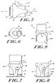
- FIGS. 5 through 9 An embodiment of the cap of the present invention is illustrated in FIGS. 5 through 9 , in which a sleeve 60 is mounted about the cap body 14.
- the sleeve 60 is movable generally along the first axis A, i.e., along the axis of motion of the lancet, and relative to the cap body 60.
- the sleeve 60 comprises an annular collar 62 and at least two legs 64A and 64B that extend from the collar 62 in the direction of the first axis A toward the distal end 34 of the cap 10.
- the legs 64A and 64B taper from an increased width proximate the collar 62 to a decreased width proximate the contact ring 16.
- the legs 64A and 64B are arcuate in cross-section and encompass only a portion of the circumference of the contact ring 16.
- the legs 64A and 64B are preferably symmetrically disposed about the circumference of the contact ring 16. Although only two legs are illustrated, one skilled in the art will appreciate that additional legs can be added without departing from the present invention. In addition, the legs need not be positioned symmetrically about the contact ring 16.
- the sleeve 60 is preferably slidable along an axis parallel to the first axis A, as indicated by arrow T in FIG. 5 .
- a longitudinally extending slot 66 can be formed in one or both of sides of the cap body 14.
- a protruding guide member 68 can be formed in one or both of the legs 64A and 64B.
- the guide member 68 is sized and shaped to slide within the slot 66 and inhibits lateral motion of the sleeve 60 relative to the cap body 14.
- the slot 66 can be formed in one or more of the legs 64A and 64B and the guide member 68 can be formed on the cap body 14.
- a spring 70 or other biasing mechanism can be provided to bias the sleeve 60 toward the distal end of the cap 10.
- the sleeve 60 is not limited to use with the cap 10 of the present invention, but can be used with the cap of any lancing device.
- the sleeve 60 allows the user to maintain a portion of the lancing device, the legs 64A and 64B of the sleeve 60, in contact with skin when the cap 14 and the contact ring 16 are removed from contact with skin, as illustrated in FIG. 7 .
- the legs 64A and 64B allow the user to maintain the opening 18 in alignment with the lancing site when the contact ring is returned into contact with dermal tissue, as illustrated in FIG. 8 .
- the sleeve legs 64A and 64B further include an anti-slip feature to prevent movement of the sleeve relative to the skin.
- An anti-slip material such as rubber or silicone, may be affixed to the contact surface of the sleeve legs to prevent movement.
- the anti-slip feature comprises a roughened surface where the sleeve legs contact the skin.
- the legs 64A and 64B can be spaced apart a distance sufficient to allow a finger 80 of the user to fit between the legs 64A and 64B.
- the surfaces 67 connecting the two legs 64A and 64B can be curved, and are preferably parabolic in shape, to further facilitate the user's finger 80.
- the legs 64A and 64B, as well as the sleeve 60 can be constructed from a flexible, resilient material, such as a flexible plastic. The preferred material of choice is ABS plastic.
- the user's finger 80 can be positioned between the legs 64A and 64B when the sleeve 60 is positioned beneath the cap 10.
- the legs 64A and 64B compress the user's finger therebetween to pinch or squeeze the dermal tissue.
- the user's finger can then be lanced and the compression of the user's finger by the legs 64A and 64B can facilitate the expression of blood from the lancing site.
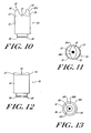
- FIGS. 10 through 13 Alternate embodiments of a cap not according to the present invention are illustrated in FIGS. 10 through 13 , in which the contact ring 16 is designed for lancing the sharp curve (or side) of the fingertip, as well as the ventral side of the fingertips.
- FIGS. 10 and 11 illustrate another embodiment of a cap not according to the present invention.
- the cap 80 includes a cap body 81 having a proximal end 86.
- a contact ring 85 is attached to the distal end 83 of the cap body 81.
- An opening 92 is provided in the contact ring 85 to allow a portion of the lancet 30 to pass through to effect puncturing of the fingertip.
- the illustrated cap body 81 can include a connector 84 for removably and replaceably connecting the proximal end 86 of the cap body 81 to the distal end of the housing 12 of the lancing device.
- the connector 84 can be sized and shaped to fit the housing 12.
- the cap 80 can be permanently affixed to the housing 12, although it is preferable that the cap 80 be removably and replaceably connected to the housing 12.
- the cap body 81 is constructed from transparent, translucent, or opaque material, such as clear or transparent plastic, or includes a transparent portion forming a window to the interior of the cap body.
- the material should be sufficiently transparent to allow the blood being expressed from within the cap body 81 to be viewed by the user.
- the transparency of the cap body 81 allows the view the amount of blood expressed for collection from the lancing, etc.
- the contact ring 85 preferably employs a pair of pressure wings 82 sized and dimensioned to accommodate the sharp curve of the fingertip therebetween.
- the pressure wings 82 thus form a recess 87 for accommodating the finger of the user. This applies the correct amount of pressure to allow for the expression of blood.
- the pressure wings extend radially outward and away from the contact ring for contacting the fingertip both during lancing and during blood sample by pressing.
- the pressure wings 82 and 82 constitute a multi-contoured surface that extends from the outer periphery of the body 81 to the opening 92.
- the multi-contoured surface 88 is designed to pressure the fingertip to maximize blood flow rate from the lancing site and to facilitate the expression of blood for sample collection.
- the illustrated multi-contoured surface 88 comprises two or more non-planar surfaces disposed at distinct angles relative to each other and with respect to a common axis.
- the pressure wings 82, 82 that constitute the multi-contoured surface 88 is comprised of a radial outer portion 88A and a curved radial inner portion 88B proximate to the opening 92.
- the transition point between the surfaces 88A and 88B can be arcuate, rounded, or sharp.
- the illustrated contact ring 85 can be constructed from plastic or other materials suitable for use in a medical instrument.
- the contact ring 85 can have a non-transparent color that is distinct from the color of the fingertip. White is the preferred color of choice. A contrasting color allows the user to better visualize the quantity of blood expressed.
- the contact ring 85 can be a separate, discrete component affixed to the cap body 81, or can be integrally formed with the cap body 81.
- the cap 80 When in use, the cap 80 is connected to the housing 12 of the lancing device, and the fingertip of the user is placed in the recess 87 formed by the pressure wings 82, 82.
- the lancet 30 of the device is deployed and passes through the opening 92 in the contact ring 85 to pierce the skin.
- the contact ring 85 is pressed into contact with the fingertip proximate to the lancing site to express blood.
- the multi-contoured surface 87 facilitates blood expression by creating a pressure gradient that extends radially inwardly towards the opening 92.
- an anti-slip feature on the contact ring 85 prevents movement of the contact ring relative to the skin surface when the contact ring is pressed into contact with the fingertip.
- the anti-slip feature can comprise a suitable anti-slip material affixed to the multi-contoured surface, or a roughened multi-contoured surface.
- the contact ring 85 can be constructed entirely of a suitable anti-slip material to provide an anti-slip feature.
- FIGS. 12 and 13 illustrate another embodiment of the cap not according to the present invention.
- the cap 90 includes a contact ring 95 attached to the distal end 97 of the cap body 94.
- An opening 124 formed in the contact ring 95 allows a portion of the lancet 30 to pass therethrough to create a puncture on the ventral side of the fingertip.
- the cap body 94 includes a connector 99 for removably and replaceably connecting a proximal end 98 of the cap body 94 to a distal end of the housing 12.
- the connector 99 can be sized and shaped to fit the housing 12.
- the cap 90 can be permanently affixed to the housing 12.
- the cap 93 is removably and replaceably connected to the housing 12.
- the cap body 94 is preferably similar to cap body 81 of FIG. 10 .
- the materials of cap 80 are also the same for cap 93.
- the material can be transparent or include a transparent portion to allow expressed blood to be viewed within the cap 93.
- the illustrated contact ring 95 has a multi-contoured surface 96 that extends from the periphery of the cap body 94 to the central opening 101.
- the multi-contoured surface 96 can include two or more surfaces disposed at distinct angles relative to each other and with respect to a common axis.
- the illustrated multi-contoured surface 96 is comprised of an outer radial portion 96A, a middle portion 96B, and an inner radial portion 96C disposed proximate to the opening 101.
- the outer, middle and inner radial portions of the cap can have any selected surface feature or shape, e.g., can be linear, stepped, or curved.
- the transition points between each surface 96A, 96B and 96C of the multi-contoured surface can have rounded, arcuate, or sharp surface features.
- the illustrated contact ring 95 can be constructed from plastic or other materials suitable for use in a medical instrument.
- the contact ring 95 can have a non-transparent color that is distinct from the color of the fingertip. White is the preferred color of choice. A contrasting color allows the user to better visualize the quantity of blood expressed.
- the contact ring 95 can be separated, discrete component affixed to the cap body 94, or can be integrally formed with the cap body 94.
- the cap 90 When in use, the cap 90 is connected to the housing 12 of the lancing device and the fingertip is placed in intimate facing contact with the ventral side finger and lanced by the lancet 30 passing through the opening 101 in the contact ring 96.
- the lancet 30 is withdrawn into the cap 90 or lancing device.
- the fingertip is squeezed into contact with the outer radial portion 96A, middle radial portion 96B, and inner radial portion 96C of the multi-contoured surface 96.
- the multi-contour surface 96 facilitates blood expression by creating a pressure gradient that extends radially inwardly toward the opening 101 from the perimeter 100 of the contact ring 95 or cap body 94.
- an anti-slip feature on the contact ring 95 prevents movement of the contact ring relative to the skin surface when the contact ring is pressed into contact with the fingertip.
- the anti-slip feature can comprise a suitable anti-slip material, such as rubber or silicone, affixed to the multi-contoured surface.
- at least a portion of the multi-contoured surface comprises a roughened contact surface to ensure friction between the contact ring and the skin.
- FIGS. 14-17 An alternative embodiment of the cap not according to the present invention is illustrated in FIGS. 14-17 in which the contact region is designed with a flexible material for lancing various surfaces of a user.
- FIGS. 14 and 15 illustrate another embodiment of the cap for use at multiple different lancing sites not according to the present invention.
- the illustrated cap 110 includes a cap body 112 that terminates at a contact ring 114 mounted at a distal end.
- the distal end 115 of the cap 110 can couple to the housing 12 via any suitable structure.
- the cap is permanently affixed to the housing, and hence not axially movable relative thereto.
- the contact ring 114 of the cap 110 can include, if desired, a multi-contoured surface 118 having a plurality of surfaces oriented at angles relative to each other.
- a central opening can also be formed therein.
- the contact ring can be a unitary structure with nominal surface features formed therein.
- the illustrated contact ring is preferably formed of a deformable, resilient, flexible material that is capable of conforming to the shape of the body region of the user placed in contact therewith.
- the contact ring can be preferably formed of a rubber material, polyurethane, latex, or other flexible material.
- the cap body 112 can also be formed of any suitable transparent, translucent, or opaque material, such as clear or transparent plastic, or can include a transparent portion forming a window to the interior of the cap body to enable the user to view the expressed blood.
- the cap can be formed of a non-transparent material.
- the contact ring 114 can be disposed in a rest position, FIG. 14 , when not in contact with a lancing site, and hence no shape is imparted to the ring.
- the contact ring When placed in contact with the lancing site, such as the ventral side of a finger, or any other suitable portion of the finger, the contact ring conforms to the shape of the lancing site, FIG. 15 .
- an anti-slip feature on the contact ring 114 prevents movement of the contact ring relative to the skin surface when the contact ring is pressed into contact with the fingertip.
- the anti-slip feature can comprise a suitable anti-slip material, such as rubber or silicone, affixed to the multi-contoured surface.
- at least a portion of the multi-contoured surface comprises a roughened contact surface to ensure friction between the contact ring and the skin.
- a cap 130 includes a cap body 132 that has mounted thereto a deformable contact ring 134.
- the illustrated contact ring 134 has edge portions 136 that extend over or outwardly from the perimeter of the cap body 132.
- the contact ring can include, if desired, a multi-contoured surface having a plurality of surfaces oriented at angles relative to each other. A central opening can also be formed therein.
- the contact ring can be a unitary structure with nominal surface features formed therein.
- the contact ring can be preferably formed of rubber material, polyurethane, latex, or other flexible material.
- the contact ring 134 can be disposed in a rest position, FIG. 16 , when not disposed in contact with a lancing site, and hence no shape is imparted to the ring.
- the contact ring 134 conforms to the shape of the lancing site, FIG. 17 .
- the overhanging portions of the deformable contact ring can 'flip' over and extend along the outer surface of the cap body 132 so it can be used on a flatter skin area, such as the forearm.
- the cap body 132 can includes a connector for removably and replaceably connecting a proximal end of the cap body 132 to a distal end of the housing 12.
- the cap 130 can be permanently affixed to the housing 12.
- the cap 130 is removably and replaceably connected to the housing 12.
Abstract
Description
- The present invention generally relates to lancing devices for lancing dermal tissue and for withdrawing a fluid sample.
- Lancets in conventional use generally have a rigid body and a sterile needle which protrudes from one end. The lancet may be used to pierce the skin, thereby enabling the collection of a blood sample from the opening. The blood is then transferred to a test collection device. Blood is most commonly taken from the fingertips, where there is generally an abundant supply. However, the nerve density in this region causes significant pain in many patients. Sampling of alternate sites, such as earlobes and limbs, is sometimes practiced to access sites which are less sensitive. These sites are also less likely to provide sufficient blood volume, and make blood transfer directly to test devices difficult.
- Repeated lancing in limited surface areas (such as fingertips) results in callous formation. This leads to increased difficulty in drawing blood and increased pain to the user. To reduce the anxiety of piercing the skin and the associated pain, many spring loaded devices have been developed.
- After puncturing the skin, conventional lancing devices are laid down and the free hand of the user squeezes blood from the puncture wound. This technique requires a clean storage site for the lancing device and a two-hand operation. Once the drop of blood is expressed from the lancing site, the user transfers the blood to a test strip of a suitable meter.
- It is often desirable to collect the expressed sample from the patient and then introduce the sample to a test device in a controlled fashion. Some blood glucose monitoring systems, for example, require that the blood sample be applied to a test device which is in contact with a test instrument. In such situations, bringing the finger of a patient directly to the test device poses some risk of contamination from blood of a previous patient. With such systems, particularly in hospital settings, it is common to lance a patient, collect a sample in a micropipette via capillary action and then deliver the sample from the pipette to the test device.
- However, these lancet devices do not extract ('squeeze out') a sufficient sample from the various surfaces for lancing. For example, the curved surface of a fingertip requires the right amount of pressure to be applied to extract blood quickly and efficiently from the patient. Therefore, there is a need for a lancet system that can accommodate the lancing of curved surfaces (e.g., fingertips) as well as flat surfaces (e.g., forearm or leg) to express sufficient volume of blood or interstitial fluid, while concomitantly reducing pain experienced by the user.
-
EP 0 783 868 A1 discloses an assembly for adjusting the piercing depth of a lancet. The assembly comprises a cap mounted on an injector and having a stop means constructed so that an end of the lancet housing abuts against the stop means after ejecting the lancet so that movement of the lancet housing is stopped while the lancet is outside of the cap, a cover element through which the lancet extends which has an opening against which the user's skin is placed, and an adjusting element which engages the cap and the cover element. -
WO 97/43962 - The present invention provides a lancing device as recited in the claims.
- In accordance with one aspect of the present invention, the cap body is transparent to facilitate viewing of the quantity of blood expressed.
- In accordance with a further aspect of the present invention, the cap is removably and replaceably connected to the distal end of the housing.
- In accordance with another aspect of the present invention, the sleeve can be biased toward the distal end of the cap body, for example, by a spring.
- These and other features and advantages of the present invention will be more fully understood by reference to the following detailed description in conjunction with the attached drawings in which like reference numerals refer to like elements through the different views. The drawings illustrate principles of the invention and, although not to scale, show relative dimensions.
-
FIG. 1 is a side elevational view of a cap for a lancing device, illustrating the cap attached to a lancing device not in accordance with the teachings of the present invention; -
FIG. 2 is a side elevational view of the cap ofFIG. 1 ; -
FIG. 3A is an end view of the cap ofFIG. 1 ; -
FIG. 3B is an end view of the cap ofFIG. 1 , wherein an anti-slip material is affixed to the contact ring; -
FIG. 4A is a side elevational view in cross section along line 4-4 ofFIGure 3 , illustrating the contact ring of the cap ofFIG. 3 ; -
FIG. 4B is a graphic representation of the pressure profile created by the cap ofFIG. 2 ; -
FIG. 4C is a cross-sectional view of an alternate embodiment of the contact ring of the lancing device not according to the present invention; -
FIG. 5 is a side elevational view of an embodiment of the cap for a lancing device of the present invention, illustrating a sleeve positioned about the cap in accordance with the teachings of the present invention -
FIG. 6 is an end view of the cap ofFIG. 5 ; -
FIG. 7 is a side elevational view of the cap ofFIG. 5 , illustrating the cap displaced from the skin in accordance with the teachings of the present invention; -
FIG. 8 is a side elevational view of the cap ofFIG. 5 , illustrating the cap in contact with the skin in accordance with the teachings of the present invention; -
FIG. 9 is a front elevational view of the cap ofFIG. 5 ; -
FIG. 10 is a front elevational view of another embodiment of a cap for a lancing device, suitable for lancing a fingertip not in accordance with the teachings of the present invention; -
FIG. 11 is an end view of the cap ofFIG. 10 ; -
FIG. 12 is a front elevational view of another embodiment of a cap for a lancing device for lancing the ventral side of a fingertip not in accordance with the teachings of the present invention; -
FIG. 13 is an end view of the cap ofFIG. 12 ; -
FIG. 14 is a side view of an alternate embodiment of a cap not according to the present invention formed of a flexible material and disposed in a rest position; -
FIG. 15 is a side view of the cap ofFIG. 14 when the contact ring contacts the lancing site; -
FIG. 16 is a side view of an alternate embodiment of a cap not according to the present invention formed of a deformable, flexible material and disposed in a rest position; and -
FIG. 17 is a side view of the cap ofFIG. 16 when the contact ring contacts the lancing site. - The present invention is directed to a cap for use with a lancing device for lancing dermal tissue to express a fluid sample, such as blood, interstitial fluid, or both. We refer below to the expression of blood for purposes of simplicity, although it is intended to encompass the expression of interstitial fluid or both. The cap of the present invention is designed to facilitate the expression of blood after the dermal tissue is lanced by increasing the pressure on the dermal tissue surrounding the lancing site. This increase in pressure results in increased blood flow from the lancing site, thereby reducing the time necessary to express a sufficient quantity of blood and eliminating the need for placing the lancing device on a surface and using the other free hand to squeeze out the sample fluid.
- Moreover, the cap of the present invention is particularly suited for collecting blood samples from lancing sites other than on the fingertip of the patient, which is the traditional location for collecting blood samples. Use of such alternative sites can be less painful to the patient and also allows the patient to "rest" his or her fingertip. Suitable alternative sites include, but are not limited to, the forearms, the upper arms, the thighs, the palms, and the abdomen of a patient. Blood sample collection at alternative sites can be problematic as manually applying sufficient pressure on the dermal tissue proximate the lancing site to collect the blood sample can be difficult and typically results in low yields. The cap of the present invention allows the user to increase the amount of pressure at the lancing site such that a sufficient quantity of blood can be expressed from the alternative sample site.
- A
cap 10 not in accordance with the present invention is illustrated inFIGS. 1 through 4 . Thecap 10 is design to be connected to the distal end of thehousing 12 of a conventional lancing device. In a conventional lancing device alancet 30 is mounted within thehousing 12 of the lancing device and is movable along a first axis, indicated by line A inFIG. 1 , relative to thehousing 12. Thelancet 30 can be driven along the first axis by the lancing device to puncture the dermal tissue. The blood sample can then be expressed for collection from the lancing site. Such conventional lancing devices are available from Lifescan, Inc. of Milpitas, CA, Palco Laboratories of Santa Cruz, CA, Therasense of Alameda, CA, and Amira Medical of Scotts Valley CA. In addition, lancing devices are described in U.S. Patent Nos.5,730,753 to Morita ,6,045,567 to Taylor , and6,071,250 to Douglas . The cap of the present invention can be used with any lancing device employing a movable lancet for lancing dermal tissue. Moreover, the present invention is intended to include any device suitable for expressing a fluid sample from a user employing different extraction techniques, including the use of lancets, hollow and solid needles or microneedles, ultrasonic devices, thermal techniques, and the like. The device can be a simple lancing device as described above, or can include devices having integrated meters or measuring devices suitable for testing an analyte, such as glucose. - The
cap 10 includes acap body 14 having aproximal end 32 and adistal end 34 as best illustrated inFIG. 2 . Acontact ring 16 is attached to thedistal end 34 of the cap body 36. Anopening 18, shown inFIGS. 3A and4 , is provided in thecontact ring 16 to allow a portion of thelancet 30 to pass therethrough to effect puncturing of the dermal tissue. - Referring to
FIG. 2 , thecap body 14 can include aconnector 20 for removably and replaceably connecting theproximal end 32 of thecap body 14 to the distal end of thehousing 12 of the lancing device. Theconnector 20 preferably is threaded to mate with corresponding threads provided in thehousing 12 of the lancing device. One skilled in the art will recognize that alternative connecting mechanisms may be used. For example, theconnector 20 can be sized and shaped to snap-fit to thehousing 12. In addition, thecap 10 can be permanently affixed to thehousing 12, although, it is preferable for thecap 14 to be removably and replaceably connected to thehousing 12. - The
cap body 14 can be constructed from a transparent, translucent or opaque material, such as a clear, transparent plastic, or includes a transparent portion forming a window to the interior of the cap body, or can be constructed of conventional non-transparent material. If transparent, the material should be sufficiently so to permit expressed blood to be viewed within thecap body 14. The transparency of thecap body 14 allows the user to view the amount of blood expressed for collection from the lancing site, as discussed in more detail below. - Referring to
FIGS. 3A and4A , thecontact ring 16 preferably has amulti-contoured surface 22 for contacting the dermal tissue both during lancing and during blood sample expression. Themulti-contoured surface 22 is oriented generally about a second axis, indicated by line B inFIG. 4A , distinct from the first axis A. In the embodiment described herein the second axis B is perpendicular to the first axis A. One skilled in the art will recognize that the second axis is not limited to this preferred orientation and that any orientation distinct from the axis of motion of the lancet can be employed. - The
multi-contoured surface 22 is designed to pressure the dermal tissue to maximize blood flow rate from the periphery of the pressured area to the center of the lancing site and to facilitate the expression of a blood sample for collection. The term multi-contoured surface as used herein is intended to include two or more surfaces oriented at distinct angles with respect to each other and with respect to a common axis. The multi-contoured surface can extend inwardly from a vertical wall, or can extend inwardly from a flat surface extending radially inwardly from the vertical wall. Those of ordinary skill will recognize that the multi-contoured surface can include any selected number of surfaces. The surface can be, according to one practice, non-planar. In one embodiment described herein, themulti-contoured surface 22 is comprised of an outerradial portion 24 and an innerradial portion 26 proximate theopening 18. The outerradial portion 24 is preferably oriented at a first angle C relative to the second axis B. The innerradial portion 26 is preferably oriented at a second angle D, distinct from the first angle C, relative to the second axis B. The outerradial portion 24 and the innerradial portion 26 can have any selected surface feature or shape, e.g., can be linear, stepped, or curved. In the illustrated embodiment, the outerradial portion 24 is generally linear from theperimeter 28 of thecontact ring 16 to the intersection with the innerradial portion 26. Alternatively, the outerradial portion 24 can be convex or concave in curvature. Additionally, the innerradial portion 26 is generally concave in curvature, but can also be linear or convex. - As shown in
FIG. 4A , the angle C, corresponding to the slope of the outerradial portion 24, is in the range between about 5° and about 15°. Additionally, the radial extent of the outerradial portion 24, generally illustrated by line E inFIG. 3A , is preferably between about 25% to about 75% of the total radius of thecontact ring 16, as measured from the center point CP of thecontact ring 16 to theperimeter 28 of thecontact ring 16. In an embodiment, the radial extent E of the outerradial portion 24 is about 50% of the total radius of thecontact ring 16. - The
contact ring 16 can be constructed from plastic or other materials suitable for use in a medical instrument. Thecontact ring 16 can have a non-transparent color, such as white, that is distinct and in contrast from the color of the dermal tissue. A contrasting color allows the user to better visualize the quantity of expressed blood. - The
contact ring 16 can be a separate, discrete component affixed to thecap body 14, or can be integrally formed with thecap body 14. - With reference to
FIG. 4B , thecontact ring 16 of thecap 10 is sized and dimensioned to be placed in intimate facing contact with the skin of the user. When placed thereagainst, the contact ring creates a pressure gradient that extends from the radial outer surface inwardly towards theopening 18. Specifically, when the skin is lanced by thelancet 30, thecontact ring 16, which is disposed about the lancing site, creates a pressure gradient that urges fluid to flow toward theopening 18, as indicated by arrows 19. - The
pressure profile 31 created by thecap 10 has pressure peaks 33 that coincide with the perimeter portion of the cap, or with the start of themulti-contoured surface 22. The pressure is a maximum at this portion since the cap contacts the skin of the user to a greater degree. When the surfaces of the multi-contoured surface extend inwardly towards theopening 18 and away from the skin, the overall pressure decreases. This forms a pressure gradient that extends from the outermost portion of thecap 10 to theopening 18. The illustratedpressure gradient 31 has decreases in a somewhat uniform manner across thesurface 24, and in a more rapid manner acrosssurface 26. Those of ordinary skill will recognize that the pressure profile will change as a function of the configuration of the contact ring. - According to an embodiment not according to the invention, illustrated in
FIG. 3B , thecontact ring 16 can include an anti-slip feature adapted to prevent thecontact ring 16 and thecap 10 from moving relative to (or across) the surface of the skin during expression of a blood sample. According to one embodiment, the anti-slip feature comprises asuitable anti-slip material 23, such as rubber or silicone, that is attached, coupled or affixed to a portion of themulti-contoured surface 22 of the contact ring. Theanti-slip material 23 ensures sufficient friction between the contact ring and the skin to resist movement of the contact ring relative to the skin surface. According to an alternate embodiment, the multi-contoured surface can be formed ro have selected surface features, such as protrusions or indentations, or can be roughened, to increase the friction between the contact ring and the skin. Alternatively, the entire contact ring can be formed from an anti-slip material to prevent movement. -
FIG. 4C illustrates another embodiment of thecontact ring 16 of thecap 10 not according to the present invention. Like reference numerals designate like or similar parts plus a superscript prime. The illustrated contact ring 16' has an axially or vertically extending outer wall or perimeter 28' that terminates at adistal end 29. Thedistal end 29 includes a firstflat face portion 29A that is adapted to press against the skin of the user during use. Theflat face portion 29A is generally perpendicular to the perimeter portion 28'. The multi-contoured surface 22' extends radially inwardly from theflat face portion 29A towards the opening 18'. The multi-contoured surface 22' extends between the annularflat face portion 29A, as indicated by the designation L. The multi-contoured surface can also be configured to include theflat face portion 29A. In this embodiment, the multi-contoured surface includes three surfaces. Optionally, an anti-slip feature, comprising an anti-slip material or a roughened surface, may be incorporated in the contact ring 16' to prevent movement of the contact ring relative to the skin surface during expression of the blood sample. - The illustrated multi-contoured surface 22' includes two or more surfaces oriented relative to each other to form different, distinct angles. In particular, the multi-contoured surface 22' includes a pair of
surfaces 25 and 27. The radiallyouter surface 25 is oriented at a first angle relative to the axis B. The radially inner surface 27 is oriented at a second angle relative to the axis B different from the first angle. As described above, thesurfaces 25 and 27 can have any selected shape or angle. - In use, the
cap 10 is connected to thehousing 12 of the lancing device and the dermal tissue is lanced by thelancet 30 passing through theopening 18 in thecontact ring 16. Thelancet 30 is then withdrawn into thecap 10 or the lancing device. Thecontact ring 16 is pressed into contact with the dermal tissue proximate the lancing site causing blood to exit the lancing site and enter thecap 10 through theopening 18. Dermal tissue is "squeezed" into contact with the outerradial portion 24 and the innerradial portion 26 of themulti-contoured surface 22. Themulti-contoured surface 22 facilitates blood expression by increasing the hydrostatic pressure on the dermal tissue in contact with theperimeter 28 of thecontact ring 16. The hydrostatic pressure on the dermal tissue decreases as the slope of the outerradial surface 24 and the inner radial surface changes toward theopening 18. This inwardly extending pressure gradient is illustrated inFIG. 4B . Experimental testing has revealed that 1.5 ml to 3 ml of blood can easily be expressed from the lancing site using thecap 10 of the present invention at sampling sites other than the finger. In addition, because thecap body 14 can be transparent and the contact ring can be a contrasting color, such as white, the user can easily monitor the volume of blood expressed. - An embodiment of the cap of the present invention is illustrated in
FIGS. 5 through 9 , in which asleeve 60 is mounted about thecap body 14. Thesleeve 60 is movable generally along the first axis A, i.e., along the axis of motion of the lancet, and relative to thecap body 60. Thesleeve 60 comprises anannular collar 62 and at least twolegs 64A and 64B that extend from thecollar 62 in the direction of the first axis A toward thedistal end 34 of thecap 10. Thelegs 64A and 64B taper from an increased width proximate thecollar 62 to a decreased width proximate thecontact ring 16. - As illustrated in
FIG. 6 , thelegs 64A and 64B are arcuate in cross-section and encompass only a portion of the circumference of thecontact ring 16. Thelegs 64A and 64B are preferably symmetrically disposed about the circumference of thecontact ring 16. Although only two legs are illustrated, one skilled in the art will appreciate that additional legs can be added without departing from the present invention. In addition, the legs need not be positioned symmetrically about thecontact ring 16. - The
sleeve 60 is preferably slidable along an axis parallel to the first axis A, as indicated by arrow T inFIG. 5 . A longitudinally extending slot 66 can be formed in one or both of sides of thecap body 14. A protrudingguide member 68 can be formed in one or both of thelegs 64A and 64B. Theguide member 68 is sized and shaped to slide within the slot 66 and inhibits lateral motion of thesleeve 60 relative to thecap body 14. Alternatively, the slot 66 can be formed in one or more of thelegs 64A and 64B and theguide member 68 can be formed on thecap body 14. - A
spring 70 or other biasing mechanism can be provided to bias thesleeve 60 toward the distal end of thecap 10. One skilled in the art will appreciate that thesleeve 60 is not limited to use with thecap 10 of the present invention, but can be used with the cap of any lancing device. - It is sometimes desirable to remove the
cap 10 and thecontact ring 16 from contact with the dermal tissue after lancing, for example, to remove pressure from the dermal tissue or to visibly inspect the lancing site. Thesleeve 60 allows the user to maintain a portion of the lancing device, thelegs 64A and 64B of thesleeve 60, in contact with skin when thecap 14 and thecontact ring 16 are removed from contact with skin, as illustrated inFIG. 7 . Importantly, thelegs 64A and 64B allow the user to maintain theopening 18 in alignment with the lancing site when the contact ring is returned into contact with dermal tissue, as illustrated inFIG. 8 . According to one embodiment, thesleeve legs 64A and 64B further include an anti-slip feature to prevent movement of the sleeve relative to the skin. An anti-slip material, such as rubber or silicone, may be affixed to the contact surface of the sleeve legs to prevent movement. Alternatively, the anti-slip feature comprises a roughened surface where the sleeve legs contact the skin. - Referring to
FIG. 9 , thelegs 64A and 64B can be spaced apart a distance sufficient to allow afinger 80 of the user to fit between thelegs 64A and 64B. Thesurfaces 67 connecting the twolegs 64A and 64B can be curved, and are preferably parabolic in shape, to further facilitate the user'sfinger 80. In addition, thelegs 64A and 64B, as well as thesleeve 60, can be constructed from a flexible, resilient material, such as a flexible plastic. The preferred material of choice is ABS plastic. As illustrated inFIGure 9 , the user'sfinger 80 can be positioned between thelegs 64A and 64B when thesleeve 60 is positioned beneath thecap 10. Thelegs 64A and 64B compress the user's finger therebetween to pinch or squeeze the dermal tissue. The user's finger can then be lanced and the compression of the user's finger by thelegs 64A and 64B can facilitate the expression of blood from the lancing site. - Alternate embodiments of a cap not according to the present invention are illustrated in
FIGS. 10 through 13 , in which thecontact ring 16 is designed for lancing the sharp curve (or side) of the fingertip, as well as the ventral side of the fingertips. -
FIGS. 10 and 11 illustrate another embodiment of a cap not according to the present invention. Thecap 80 includes acap body 81 having aproximal end 86. Acontact ring 85 is attached to thedistal end 83 of thecap body 81. Anopening 92 is provided in thecontact ring 85 to allow a portion of thelancet 30 to pass through to effect puncturing of the fingertip. The illustratedcap body 81 can include aconnector 84 for removably and replaceably connecting theproximal end 86 of thecap body 81 to the distal end of thehousing 12 of the lancing device. For example, theconnector 84 can be sized and shaped to fit thehousing 12. Thecap 80 can be permanently affixed to thehousing 12, although it is preferable that thecap 80 be removably and replaceably connected to thehousing 12. - The
cap body 81 is constructed from transparent, translucent, or opaque material, such as clear or transparent plastic, or includes a transparent portion forming a window to the interior of the cap body. The material should be sufficiently transparent to allow the blood being expressed from within thecap body 81 to be viewed by the user. The transparency of thecap body 81 allows the view the amount of blood expressed for collection from the lancing, etc. - The
contact ring 85 preferably employs a pair ofpressure wings 82 sized and dimensioned to accommodate the sharp curve of the fingertip therebetween. Thepressure wings 82 thus form arecess 87 for accommodating the finger of the user. This applies the correct amount of pressure to allow for the expression of blood. - Referring to
FIG. 11 , the pressure wings extend radially outward and away from the contact ring for contacting the fingertip both during lancing and during blood sample by pressing. Thepressure wings body 81 to theopening 92. Themulti-contoured surface 88 is designed to pressure the fingertip to maximize blood flow rate from the lancing site and to facilitate the expression of blood for sample collection. The illustratedmulti-contoured surface 88 comprises two or more non-planar surfaces disposed at distinct angles relative to each other and with respect to a common axis. For example, thepressure wings multi-contoured surface 88 is comprised of a radialouter portion 88A and a curved radial inner portion 88B proximate to theopening 92. The transition point between thesurfaces 88A and 88B can be arcuate, rounded, or sharp. - The illustrated
contact ring 85 can be constructed from plastic or other materials suitable for use in a medical instrument. Thecontact ring 85 can have a non-transparent color that is distinct from the color of the fingertip. White is the preferred color of choice. A contrasting color allows the user to better visualize the quantity of blood expressed. Thecontact ring 85 can be a separate, discrete component affixed to thecap body 81, or can be integrally formed with thecap body 81. - When in use, the
cap 80 is connected to thehousing 12 of the lancing device, and the fingertip of the user is placed in therecess 87 formed by thepressure wings lancet 30 of the device is deployed and passes through theopening 92 in thecontact ring 85 to pierce the skin. Thecontact ring 85 is pressed into contact with the fingertip proximate to the lancing site to express blood. Themulti-contoured surface 87 facilitates blood expression by creating a pressure gradient that extends radially inwardly towards theopening 92. According to an alternate embodiment, an anti-slip feature on thecontact ring 85 prevents movement of the contact ring relative to the skin surface when the contact ring is pressed into contact with the fingertip. As discussed, the anti-slip feature can comprise a suitable anti-slip material affixed to the multi-contoured surface, or a roughened multi-contoured surface. Alternatively, thecontact ring 85 can be constructed entirely of a suitable anti-slip material to provide an anti-slip feature. -
FIGS. 12 and 13 illustrate another embodiment of the cap not according to the present invention. As illustrated inFIG. 12 , thecap 90 includes acontact ring 95 attached to thedistal end 97 of thecap body 94. An opening 124 formed in thecontact ring 95 allows a portion of thelancet 30 to pass therethrough to create a puncture on the ventral side of the fingertip. - The
cap body 94 includes aconnector 99 for removably and replaceably connecting aproximal end 98 of thecap body 94 to a distal end of thehousing 12. For example, theconnector 99 can be sized and shaped to fit thehousing 12. Also, thecap 90 can be permanently affixed to thehousing 12. Preferably, the cap 93 is removably and replaceably connected to thehousing 12. Thecap body 94 is preferably similar to capbody 81 ofFIG. 10 . The materials ofcap 80 are also the same for cap 93. The material can be transparent or include a transparent portion to allow expressed blood to be viewed within the cap 93. - The illustrated
contact ring 95 has amulti-contoured surface 96 that extends from the periphery of thecap body 94 to thecentral opening 101. Themulti-contoured surface 96 can include two or more surfaces disposed at distinct angles relative to each other and with respect to a common axis. For example, the illustratedmulti-contoured surface 96 is comprised of an outerradial portion 96A, a middle portion 96B, and an innerradial portion 96C disposed proximate to theopening 101. The outer, middle and inner radial portions of the cap can have any selected surface feature or shape, e.g., can be linear, stepped, or curved. Moreover, the transition points between eachsurface - The illustrated
contact ring 95 can be constructed from plastic or other materials suitable for use in a medical instrument. Thecontact ring 95 can have a non-transparent color that is distinct from the color of the fingertip. White is the preferred color of choice. A contrasting color allows the user to better visualize the quantity of blood expressed. Similarly to cap 80, thecontact ring 95 can be separated, discrete component affixed to thecap body 94, or can be integrally formed with thecap body 94. - When in use, the
cap 90 is connected to thehousing 12 of the lancing device and the fingertip is placed in intimate facing contact with the ventral side finger and lanced by thelancet 30 passing through theopening 101 in thecontact ring 96. Thelancet 30 is withdrawn into thecap 90 or lancing device. The fingertip is squeezed into contact with the outerradial portion 96A, middle radial portion 96B, and innerradial portion 96C of themulti-contoured surface 96. Themulti-contour surface 96 facilitates blood expression by creating a pressure gradient that extends radially inwardly toward the opening 101 from theperimeter 100 of thecontact ring 95 orcap body 94. According to one embodiment, an anti-slip feature on thecontact ring 95 prevents movement of the contact ring relative to the skin surface when the contact ring is pressed into contact with the fingertip. As discussed, the anti-slip feature can comprise a suitable anti-slip material, such as rubber or silicone, affixed to the multi-contoured surface. Alternatively, at least a portion of the multi-contoured surface comprises a roughened contact surface to ensure friction between the contact ring and the skin. - An alternative embodiment of the cap not according to the present invention is illustrated in
FIGS. 14-17 in which the contact region is designed with a flexible material for lancing various surfaces of a user. -
FIGS. 14 and 15 illustrate another embodiment of the cap for use at multiple different lancing sites not according to the present invention. The illustratedcap 110 includes acap body 112 that terminates at acontact ring 114 mounted at a distal end. The distal end 115 of thecap 110 can couple to thehousing 12 via any suitable structure. According to a preferred embodiment, the cap is permanently affixed to the housing, and hence not axially movable relative thereto. Thecontact ring 114 of thecap 110 can include, if desired, a multi-contoured surface 118 having a plurality of surfaces oriented at angles relative to each other. A central opening can also be formed therein. According to an alternate embodiment, the contact ring can be a unitary structure with nominal surface features formed therein. - The illustrated contact ring is preferably formed of a deformable, resilient, flexible material that is capable of conforming to the shape of the body region of the user placed in contact therewith. The contact ring can be preferably formed of a rubber material, polyurethane, latex, or other flexible material. The
cap body 112 can also be formed of any suitable transparent, translucent, or opaque material, such as clear or transparent plastic, or can include a transparent portion forming a window to the interior of the cap body to enable the user to view the expressed blood. Alternatively, the cap can be formed of a non-transparent material. - The
contact ring 114 can be disposed in a rest position,FIG. 14 , when not in contact with a lancing site, and hence no shape is imparted to the ring. When placed in contact with the lancing site, such as the ventral side of a finger, or any other suitable portion of the finger, the contact ring conforms to the shape of the lancing site,FIG. 15 . According to one embodiment, an anti-slip feature on thecontact ring 114 prevents movement of the contact ring relative to the skin surface when the contact ring is pressed into contact with the fingertip. As discussed, the anti-slip feature can comprise a suitable anti-slip material, such as rubber or silicone, affixed to the multi-contoured surface. Alternatively, at least a portion of the multi-contoured surface comprises a roughened contact surface to ensure friction between the contact ring and the skin. - According to an alternate embodiment, as illustrated in
FIGS. 16 and 17 , acap 130 includes acap body 132 that has mounted thereto adeformable contact ring 134. The illustratedcontact ring 134 hasedge portions 136 that extend over or outwardly from the perimeter of thecap body 132. The contact ring can include, if desired, a multi-contoured surface having a plurality of surfaces oriented at angles relative to each other. A central opening can also be formed therein. According to an alternate embodiment, the contact ring can be a unitary structure with nominal surface features formed therein. - The contact ring can be preferably formed of rubber material, polyurethane, latex, or other flexible material. The
contact ring 134 can be disposed in a rest position,FIG. 16 , when not disposed in contact with a lancing site, and hence no shape is imparted to the ring. When placed in contact with the lancing site, such as the ventral side of a finger, or any other suitable portion of the finger, thecontact ring 134 conforms to the shape of the lancing site,FIG. 17 . Moreover, when disposed in this position, the overhanging portions of the deformable contact ring, can 'flip' over and extend along the outer surface of thecap body 132 so it can be used on a flatter skin area, such as the forearm. - The
cap body 132 can includes a connector for removably and replaceably connecting a proximal end of thecap body 132 to a distal end of thehousing 12. According to one practice, thecap 130 can be permanently affixed to thehousing 12. Preferably, thecap 130 is removably and replaceably connected to thehousing 12. - Since certain changes may be made in the above constructions without departing from the scope of the invention, it is intended that all matter contained in the above description or shown in the accompanying drawings be interpreted as illustrative and not in a limiting sense.
Claims (5)
- A lancing device for lancing dermal tissue, the lancing device including a housing (12) having a proximal end and a distal end, a lancet (30) mounted within the housing (12), the lancet (30) being movable along a first axis relative to the housing (12), and a cap (10), the cap (10) comprising:a cap body (14) having a proximal end and a distal end, the proximal end of the cap body (14) removeably and replaceably connected to the distal end of the housing (12),a contact ring (16) attached to the distal end of the cap body (14), the contact ring (16) including an opening (18) for a portion of the lancet (30) to pass therethrough; anda sleeve (60) mounted about the cap body (14), the sleeve (60) being movable generally along the first axis and relative to the cap body (14), the sleeve (60) including at least two legs (64A, 64B) for maintaining contact with the dermal tissue during expression of a blood sample after lancing the dermal tissue, characterised in that:the legs (64A, 64B) include an anti-slip feature to prevent movement of the legs (64A, 64B) relative to the skin, wherein the anti-slip feature comprises a roughened surface to increase friction between the legs (64A, 64B) and the skin.
- The lancing device of claim 1, wherein the sleeve (60) is biased toward the distal end of the cap body (14).
- The lancing device of claim 1 or claim 2, wherein the legs (64A, 64B) are spaced apart to permit a user's finger in the space therebetween.
- The lancing device of any one of claims 1 to 3, wherein the legs (64A, 64B) are constructed from a resilient material such that the legs (64A, 64B) act to compress the user's finger when positioned therebetween.
- The lancing device of any preceding claim, wherein the sleeve (60) comprises an annular collar (62), and the at least two legs (64A, 64B) extend from the collar (62) in the direction of the first axis toward the distal end (34) of the cap (10), wherein the legs (64A, 64B) taper from an increased width proximate the collar to a decreased width proximate the contact ring.
Applications Claiming Priority (3)
| Application Number | Priority Date | Filing Date | Title |
|---|---|---|---|
| US21080800P | 2000-06-09 | 2000-06-09 | |
| US26151301P | 2001-01-12 | 2001-01-12 | |
| EP01944344A EP1318752A2 (en) | 2000-06-09 | 2001-06-08 | Cap for a lancing device |
Related Parent Applications (2)
| Application Number | Title | Priority Date | Filing Date |
|---|---|---|---|
| EP01944344.9 Division | 2001-06-08 | ||
| EP01944344A Division EP1318752A2 (en) | 2000-06-09 | 2001-06-08 | Cap for a lancing device |
Publications (3)
| Publication Number | Publication Date |
|---|---|
| EP1787583A2 EP1787583A2 (en) | 2007-05-23 |
| EP1787583A3 EP1787583A3 (en) | 2010-02-17 |
| EP1787583B1 true EP1787583B1 (en) | 2012-02-01 |
Family
ID=26905524
Family Applications (2)
| Application Number | Title | Priority Date | Filing Date |
|---|---|---|---|
| EP07075043A Expired - Lifetime EP1787583B1 (en) | 2000-06-09 | 2001-06-08 | Cap for a lancing drive |
| EP01944344A Withdrawn EP1318752A2 (en) | 2000-06-09 | 2001-06-08 | Cap for a lancing device |
Family Applications After (1)
| Application Number | Title | Priority Date | Filing Date |
|---|---|---|---|
| EP01944344A Withdrawn EP1318752A2 (en) | 2000-06-09 | 2001-06-08 | Cap for a lancing device |
Country Status (17)
| Country | Link |
|---|---|
| US (3) | US6706049B2 (en) |
| EP (2) | EP1787583B1 (en) |
| JP (1) | JP4772263B2 (en) |
| KR (1) | KR20030045678A (en) |
| CN (1) | CN100515336C (en) |
| AT (1) | ATE543437T1 (en) |
| AU (2) | AU6676601A (en) |
| CA (1) | CA2412401C (en) |
| CZ (1) | CZ20024006A3 (en) |
| ES (1) | ES2378699T3 (en) |
| IL (2) | IL153295A0 (en) |
| MX (1) | MXPA02012175A (en) |
| NO (1) | NO20025880L (en) |
| PL (2) | PL197142B1 (en) |
| RU (1) | RU2269954C2 (en) |
| TW (1) | TWI305492B (en) |
| WO (1) | WO2001095806A2 (en) |
Families Citing this family (144)
| Publication number | Priority date | Publication date | Assignee | Title |
|---|---|---|---|---|
| US6706000B2 (en) * | 1997-11-21 | 2004-03-16 | Amira Medical | Methods and apparatus for expressing body fluid from an incision |
| US6036924A (en) * | 1997-12-04 | 2000-03-14 | Hewlett-Packard Company | Cassette of lancet cartridges for sampling blood |
| US6391005B1 (en) | 1998-03-30 | 2002-05-21 | Agilent Technologies, Inc. | Apparatus and method for penetration with shaft having a sensor for sensing penetration depth |
| EP1787583B1 (en) * | 2000-06-09 | 2012-02-01 | Diabetes Diagnostics, Inc. | Cap for a lancing drive |
| DE10057832C1 (en) * | 2000-11-21 | 2002-02-21 | Hartmann Paul Ag | Blood analysis device has syringe mounted in casing, annular mounting carrying needles mounted behind test strip and being swiveled so that needle can be pushed through strip and aperture in casing to take blood sample |
| US8641644B2 (en) | 2000-11-21 | 2014-02-04 | Sanofi-Aventis Deutschland Gmbh | Blood testing apparatus having a rotatable cartridge with multiple lancing elements and testing means |
| BR0206604A (en) | 2001-01-22 | 2004-02-17 | Hoffmann La Roche | Lancet device that has capillary action |
| JP3934107B2 (en) * | 2001-06-08 | 2007-06-20 | エフ ホフマン−ラ ロッシュ アクチェン ゲゼルシャフト | Test strip for collecting body fluid and method for collecting body fluid |
| US20020188223A1 (en) * | 2001-06-08 | 2002-12-12 | Edward Perez | Devices and methods for the expression of bodily fluids from an incision |
| EP1404234B1 (en) * | 2001-06-12 | 2011-02-09 | Pelikan Technologies Inc. | Apparatus for improving success rate of blood yield from a fingerstick |
| US7682318B2 (en) * | 2001-06-12 | 2010-03-23 | Pelikan Technologies, Inc. | Blood sampling apparatus and method |
| US9427532B2 (en) | 2001-06-12 | 2016-08-30 | Sanofi-Aventis Deutschland Gmbh | Tissue penetration device |
| US7025774B2 (en) | 2001-06-12 | 2006-04-11 | Pelikan Technologies, Inc. | Tissue penetration device |
| US7981056B2 (en) | 2002-04-19 | 2011-07-19 | Pelikan Technologies, Inc. | Methods and apparatus for lancet actuation |
| US8337419B2 (en) | 2002-04-19 | 2012-12-25 | Sanofi-Aventis Deutschland Gmbh | Tissue penetration device |
| US9795747B2 (en) | 2010-06-02 | 2017-10-24 | Sanofi-Aventis Deutschland Gmbh | Methods and apparatus for lancet actuation |
| ATE485766T1 (en) | 2001-06-12 | 2010-11-15 | Pelikan Technologies Inc | ELECTRICAL ACTUATING ELEMENT FOR A LANCET |
| US7749174B2 (en) | 2001-06-12 | 2010-07-06 | Pelikan Technologies, Inc. | Method and apparatus for lancet launching device intergrated onto a blood-sampling cartridge |
| DE60234598D1 (en) | 2001-06-12 | 2010-01-14 | Pelikan Technologies Inc | SELF-OPTIMIZING LANZET DEVICE WITH ADAPTANT FOR TEMPORAL FLUCTUATIONS OF SKIN PROPERTIES |
| US9226699B2 (en) | 2002-04-19 | 2016-01-05 | Sanofi-Aventis Deutschland Gmbh | Body fluid sampling module with a continuous compression tissue interface surface |
| US20030040683A1 (en) * | 2001-07-06 | 2003-02-27 | Peter Rule | Site selection for determining analyte concentration in living tissue |
| US6966880B2 (en) * | 2001-10-16 | 2005-11-22 | Agilent Technologies, Inc. | Universal diagnostic platform |
| US20040098010A1 (en) * | 2001-10-22 | 2004-05-20 | Glenn Davison | Confuser crown skin pricker |
| US7004928B2 (en) | 2002-02-08 | 2006-02-28 | Rosedale Medical, Inc. | Autonomous, ambulatory analyte monitor or drug delivery device |
| US9248267B2 (en) | 2002-04-19 | 2016-02-02 | Sanofi-Aventis Deustchland Gmbh | Tissue penetration device |
| US7717863B2 (en) | 2002-04-19 | 2010-05-18 | Pelikan Technologies, Inc. | Method and apparatus for penetrating tissue |
| US7175642B2 (en) | 2002-04-19 | 2007-02-13 | Pelikan Technologies, Inc. | Methods and apparatus for lancet actuation |
| US9795334B2 (en) | 2002-04-19 | 2017-10-24 | Sanofi-Aventis Deutschland Gmbh | Method and apparatus for penetrating tissue |
| US7547287B2 (en) | 2002-04-19 | 2009-06-16 | Pelikan Technologies, Inc. | Method and apparatus for penetrating tissue |
| US7371247B2 (en) * | 2002-04-19 | 2008-05-13 | Pelikan Technologies, Inc | Method and apparatus for penetrating tissue |
| US7291117B2 (en) | 2002-04-19 | 2007-11-06 | Pelikan Technologies, Inc. | Method and apparatus for penetrating tissue |
| US7563232B2 (en) * | 2002-04-19 | 2009-07-21 | Pelikan Technologies, Inc. | Method and apparatus for penetrating tissue |
| US8702624B2 (en) | 2006-09-29 | 2014-04-22 | Sanofi-Aventis Deutschland Gmbh | Analyte measurement device with a single shot actuator |
| US7892185B2 (en) * | 2002-04-19 | 2011-02-22 | Pelikan Technologies, Inc. | Method and apparatus for body fluid sampling and analyte sensing |
| US7909778B2 (en) | 2002-04-19 | 2011-03-22 | Pelikan Technologies, Inc. | Method and apparatus for penetrating tissue |
| US8360992B2 (en) | 2002-04-19 | 2013-01-29 | Sanofi-Aventis Deutschland Gmbh | Method and apparatus for penetrating tissue |
| US7901362B2 (en) | 2002-04-19 | 2011-03-08 | Pelikan Technologies, Inc. | Method and apparatus for penetrating tissue |
| US8221334B2 (en) | 2002-04-19 | 2012-07-17 | Sanofi-Aventis Deutschland Gmbh | Method and apparatus for penetrating tissue |
| US7892183B2 (en) | 2002-04-19 | 2011-02-22 | Pelikan Technologies, Inc. | Method and apparatus for body fluid sampling and analyte sensing |
| US7648468B2 (en) | 2002-04-19 | 2010-01-19 | Pelikon Technologies, Inc. | Method and apparatus for penetrating tissue |
| US8579831B2 (en) | 2002-04-19 | 2013-11-12 | Sanofi-Aventis Deutschland Gmbh | Method and apparatus for penetrating tissue |
| US8784335B2 (en) | 2002-04-19 | 2014-07-22 | Sanofi-Aventis Deutschland Gmbh | Body fluid sampling device with a capacitive sensor |
| US9314194B2 (en) | 2002-04-19 | 2016-04-19 | Sanofi-Aventis Deutschland Gmbh | Tissue penetration device |
| US7331931B2 (en) | 2002-04-19 | 2008-02-19 | Pelikan Technologies, Inc. | Method and apparatus for penetrating tissue |
| US7491178B2 (en) * | 2002-04-19 | 2009-02-17 | Pelikan Technologies, Inc. | Method and apparatus for penetrating tissue |
| US7232451B2 (en) | 2002-04-19 | 2007-06-19 | Pelikan Technologies, Inc. | Method and apparatus for penetrating tissue |
| US7229458B2 (en) | 2002-04-19 | 2007-06-12 | Pelikan Technologies, Inc. | Method and apparatus for penetrating tissue |
| US7674232B2 (en) * | 2002-04-19 | 2010-03-09 | Pelikan Technologies, Inc. | Method and apparatus for penetrating tissue |
| US7481776B2 (en) * | 2002-04-19 | 2009-01-27 | Pelikan Technologies, Inc. | Method and apparatus for penetrating tissue |
| US8267870B2 (en) | 2002-04-19 | 2012-09-18 | Sanofi-Aventis Deutschland Gmbh | Method and apparatus for body fluid sampling with hybrid actuation |
| US7226461B2 (en) | 2002-04-19 | 2007-06-05 | Pelikan Technologies, Inc. | Method and apparatus for a multi-use body fluid sampling device with sterility barrier release |
| US7297122B2 (en) | 2002-04-19 | 2007-11-20 | Pelikan Technologies, Inc. | Method and apparatus for penetrating tissue |
| US7976476B2 (en) * | 2002-04-19 | 2011-07-12 | Pelikan Technologies, Inc. | Device and method for variable speed lancet |
| US7141058B2 (en) * | 2002-04-19 | 2006-11-28 | Pelikan Technologies, Inc. | Method and apparatus for a body fluid sampling device using illumination |
| US20120296233A9 (en) * | 2002-09-05 | 2012-11-22 | Freeman Dominique M | Methods and apparatus for an analyte detecting device |
| US20060270998A1 (en) * | 2002-11-13 | 2006-11-30 | Marti Karim-Frederic | Device transforming the pain of a syringe needle into a tolerable feeling |
| US20060184189A1 (en) * | 2002-11-15 | 2006-08-17 | Lorin Olson | Cap for a dermal tissue lancing device |
| CN100415166C (en) * | 2002-11-15 | 2008-09-03 | 生命扫描有限公司 | Cap for a dermal tissue lancing device |
| US8574895B2 (en) | 2002-12-30 | 2013-11-05 | Sanofi-Aventis Deutschland Gmbh | Method and apparatus using optical techniques to measure analyte levels |
| AU2003300154A1 (en) * | 2002-12-31 | 2004-07-29 | Pelikan Technologies Inc. | Method and apparatus for loading penetrating members |
| WO2004064635A1 (en) * | 2003-01-17 | 2004-08-05 | Matsushita Electric Industrial Co., Ltd. | Apparatus for measuring biological component |
| US20040162573A1 (en) * | 2003-02-19 | 2004-08-19 | Kheiri Mohammad A. | Endcap for lancing device and method of use |
| WO2004080306A1 (en) * | 2003-03-06 | 2004-09-23 | Lifescan, Inc. | System and method for piercing dermal tissue |
| US7052652B2 (en) | 2003-03-24 | 2006-05-30 | Rosedale Medical, Inc. | Analyte concentration detection devices and methods |
| EP1628567B1 (en) | 2003-05-30 | 2010-08-04 | Pelikan Technologies Inc. | Method and apparatus for fluid injection |
| DK1633235T3 (en) | 2003-06-06 | 2014-08-18 | Sanofi Aventis Deutschland | Apparatus for sampling body fluid and detecting analyte |
| WO2006001797A1 (en) | 2004-06-14 | 2006-01-05 | Pelikan Technologies, Inc. | Low pain penetrating |
| US8148164B2 (en) | 2003-06-20 | 2012-04-03 | Roche Diagnostics Operations, Inc. | System and method for determining the concentration of an analyte in a sample fluid |
| US8058077B2 (en) | 2003-06-20 | 2011-11-15 | Roche Diagnostics Operations, Inc. | Method for coding information on a biosensor test strip |
| JP2007503913A (en) * | 2003-09-03 | 2007-03-01 | ファセット・テクノロジーズ・エルエルシー | End cap for body fluid collection device |
| US20090105612A1 (en) * | 2003-09-18 | 2009-04-23 | Facet Technologies, Llc | Lancing device end cap with pressure-actuated surface features |
| WO2005035018A2 (en) * | 2003-09-18 | 2005-04-21 | Facet Technologies, Llc | Lancing device end cap with rocking-actuated surface features |
| WO2005034778A1 (en) * | 2003-09-18 | 2005-04-21 | Facet Technologies, Llc | Lancing device end cap with flexing contact elements |
| US8282576B2 (en) | 2003-09-29 | 2012-10-09 | Sanofi-Aventis Deutschland Gmbh | Method and apparatus for an improved sample capture device |
| EP1680014A4 (en) | 2003-10-14 | 2009-01-21 | Pelikan Technologies Inc | Method and apparatus for a variable user interface |
| US7299082B2 (en) * | 2003-10-31 | 2007-11-20 | Abbott Diabetes Care, Inc. | Method of calibrating an analyte-measurement device, and associated methods, devices and systems |
| US20050096686A1 (en) * | 2003-10-31 | 2005-05-05 | Allen John J. | Lancing device with trigger mechanism for penetration depth control |
| EP1706026B1 (en) | 2003-12-31 | 2017-03-01 | Sanofi-Aventis Deutschland GmbH | Method and apparatus for improving fluidic flow and sample capture |
| US7822454B1 (en) | 2005-01-03 | 2010-10-26 | Pelikan Technologies, Inc. | Fluid sampling device with improved analyte detecting member configuration |
| EP1706016A4 (en) * | 2003-12-31 | 2017-07-05 | Sanofi-Aventis Deutschland GmbH | Improved penetrating member control using auto-pre-tent |
| US20050159768A1 (en) * | 2004-01-15 | 2005-07-21 | Home Diagnostics, Inc. | Lancing device |
| DE102004002874A1 (en) * | 2004-01-20 | 2005-08-11 | Roche Diagnostics Gmbh | Analyzer for analysis of blood samples |
| US7670352B1 (en) | 2004-03-24 | 2010-03-02 | Caribbean Medical Brokers, Inc. | Adjustable tip with integrated detent for blood lancet system |
| US20050215923A1 (en) * | 2004-03-26 | 2005-09-29 | Wiegel Christopher D | Fingertip conforming fluid expression cap |
| EP1778085A1 (en) * | 2004-04-01 | 2007-05-02 | Bayer Healthcare, LLC | Endcap for a vacuum lancing fixture |
| US20050234489A1 (en) * | 2004-04-16 | 2005-10-20 | John Allen | Method for lancing a dermal tissue target site |
| US20050234491A1 (en) * | 2004-04-16 | 2005-10-20 | Allen John J | Method for lancing a dermal tissue target site employing a dermal tissue lancing device with a tiltable cap |
| US20050234486A1 (en) * | 2004-04-16 | 2005-10-20 | Allen John J | Apparatus for extracting bodily fluid |
| GB0409354D0 (en) * | 2004-04-27 | 2004-06-02 | Owen Mumford Ltd | Removal of needles |
| US9101302B2 (en) * | 2004-05-03 | 2015-08-11 | Abbott Diabetes Care Inc. | Analyte test device |
| US8828203B2 (en) | 2004-05-20 | 2014-09-09 | Sanofi-Aventis Deutschland Gmbh | Printable hydrogels for biosensors |
| WO2005120197A2 (en) * | 2004-06-03 | 2005-12-22 | Pelikan Technologies, Inc. | Tissue interface on a fluid sampling device |
| US9775553B2 (en) | 2004-06-03 | 2017-10-03 | Sanofi-Aventis Deutschland Gmbh | Method and apparatus for a fluid sampling device |
| EP1765194A4 (en) | 2004-06-03 | 2010-09-29 | Pelikan Technologies Inc | Method and apparatus for a fluid sampling device |
| WO2005120199A2 (en) * | 2004-06-03 | 2005-12-22 | Pelikan Technologies, Inc. | Methods and apparatus for an integrated sample capture and analysis disposable |
| US7384402B2 (en) | 2004-06-10 | 2008-06-10 | Roche Diagnostics Operations, Inc. | Expression pad |
| US7569126B2 (en) | 2004-06-18 | 2009-08-04 | Roche Diagnostics Operations, Inc. | System and method for quality assurance of a biosensor test strip |
| US7766845B2 (en) * | 2004-06-21 | 2010-08-03 | Roche Diagnostics Operations, Inc. | Disposable lancet and lancing cap combination for increased hygiene |
| US7512432B2 (en) | 2004-07-27 | 2009-03-31 | Abbott Laboratories | Sensor array |
| US20080195131A1 (en) * | 2004-07-28 | 2008-08-14 | Facet Technologies, Llc | Lancing Device End Cap With Rocking-Actuated Surface Features |
| PL1632179T3 (en) * | 2004-09-02 | 2008-07-31 | Nipro Corp | Lancet with needle protector |
| US8652831B2 (en) | 2004-12-30 | 2014-02-18 | Sanofi-Aventis Deutschland Gmbh | Method and apparatus for analyte measurement test time |
| US20060281187A1 (en) | 2005-06-13 | 2006-12-14 | Rosedale Medical, Inc. | Analyte detection devices and methods with hematocrit/volume correction and feedback control |
| EP1928304B1 (en) | 2005-09-30 | 2012-10-24 | Intuity Medical, Inc. | Catalysts for body fluid sample extraction |
| US8801631B2 (en) * | 2005-09-30 | 2014-08-12 | Intuity Medical, Inc. | Devices and methods for facilitating fluid transport |
| US20070093863A1 (en) * | 2005-10-20 | 2007-04-26 | Pugh Jerry T | Cap for a dermal tissue lancing device |
| US20070093864A1 (en) * | 2005-10-20 | 2007-04-26 | Pugh Jerry T | Method for lancing a dermal tissue target site |
| CN101296656A (en) * | 2005-11-29 | 2008-10-29 | Ttm株式会社 | Body fluid sampler and method therefor |
| GB0524604D0 (en) * | 2005-12-02 | 2006-01-11 | Owen Mumford Ltd | Injection method and apparatus |
| GB2434103B (en) | 2006-01-12 | 2009-11-25 | Owen Mumford Ltd | Lancet firing device |
| WO2007089930A2 (en) * | 2006-01-31 | 2007-08-09 | Facet Technologies, Llc | Lancet with cap-removal guidance |
| US7885698B2 (en) | 2006-02-28 | 2011-02-08 | Abbott Diabetes Care Inc. | Method and system for providing continuous calibration of implantable analyte sensors |
| US20070255178A1 (en) * | 2006-04-27 | 2007-11-01 | Lifescan Scotland, Ltd. | Method for lancing a target site in low ambient light conditions |
| US20090163944A1 (en) * | 2006-05-10 | 2009-06-25 | Panasonic Corporation | Piercing instrument and piercing needle cartridge |
| US7909842B2 (en) * | 2006-06-15 | 2011-03-22 | Abbott Diabetes Care Inc. | Lancing devices having depth adjustment assembly |
| US20080065130A1 (en) * | 2006-08-22 | 2008-03-13 | Paul Patel | Elastomeric toroidal ring for blood expression |
| MX340230B (en) | 2007-04-30 | 2016-07-01 | F Hoffmann-La Roche Ag * | Instrument and system for producing a sample of a body liquid and for analysis thereof. |
| US20090099437A1 (en) * | 2007-10-11 | 2009-04-16 | Vadim Yuzhakov | Lancing Depth Adjustment Via Moving Cap |
| WO2009126900A1 (en) | 2008-04-11 | 2009-10-15 | Pelikan Technologies, Inc. | Method and apparatus for analyte detecting device |
| WO2009145920A1 (en) * | 2008-05-30 | 2009-12-03 | Intuity Medical, Inc. | Body fluid sampling device -- sampling site interface |
| US9636051B2 (en) | 2008-06-06 | 2017-05-02 | Intuity Medical, Inc. | Detection meter and mode of operation |
| EP2299904B1 (en) | 2008-06-06 | 2019-09-11 | Intuity Medical, Inc. | Medical measurement method |
| GB0814747D0 (en) * | 2008-08-13 | 2008-09-17 | Owen Mumford Ltd | Autoinjection devices |
| US8123772B2 (en) * | 2008-08-14 | 2012-02-28 | Abbott Diabetes Care Inc. | Cap for lancing device with adjustable mode of operation |
| US8092476B2 (en) * | 2008-08-14 | 2012-01-10 | Abbott Diabetes Care Inc. | Adjustable cap and lancing device and method of use |
| RU2466754C1 (en) * | 2008-09-29 | 2012-11-20 | Вифор (Интернациональ) Аг | Assembled cap and method for making it |
| GB2465390A (en) | 2008-11-17 | 2010-05-19 | Owen Mumford Ltd | Syringe needle cover remover |
| US9375169B2 (en) | 2009-01-30 | 2016-06-28 | Sanofi-Aventis Deutschland Gmbh | Cam drive for managing disposable penetrating member actions with a single motor and motor and control system |
| EP2226014B1 (en) * | 2009-03-06 | 2011-12-14 | Christophe Baudouin | Eye sampling device |
| WO2011014260A1 (en) * | 2009-07-30 | 2011-02-03 | Becton, Dickinson And Company | Lancing device having saddle-shaped tip |
| EP3106871B1 (en) | 2009-11-30 | 2021-10-27 | Intuity Medical, Inc. | A method of verifying the accuracy of the operation of an analyte monitoring device |
| US8965476B2 (en) | 2010-04-16 | 2015-02-24 | Sanofi-Aventis Deutschland Gmbh | Tissue penetration device |
| CA2803797A1 (en) | 2010-06-25 | 2011-12-29 | Intuity Medical, Inc. | Analyte monitoring methods and systems |
| US8486717B2 (en) | 2011-01-18 | 2013-07-16 | Symbolics, Llc | Lateral flow assays using two dimensional features |
| EP3407064B1 (en) | 2011-08-03 | 2020-04-22 | Intuity Medical, Inc. | Body fluid sampling arrangement |
| US9874556B2 (en) | 2012-07-18 | 2018-01-23 | Symbolics, Llc | Lateral flow assays using two dimensional features |
| WO2014099907A1 (en) | 2012-12-18 | 2014-06-26 | Abbott Diabetes Care Inc. | Dermal layer analyte sensing devices and methods |
| US9668686B2 (en) | 2013-03-15 | 2017-06-06 | Abbott Diabetes Care Inc. | In vivo glucose sensing in an increased perfusion dermal layer |
| US10729386B2 (en) | 2013-06-21 | 2020-08-04 | Intuity Medical, Inc. | Analyte monitoring system with audible feedback |
| CN105765384B (en) | 2013-09-13 | 2018-02-09 | Symbolics有限责任公司 | Detected with the lateral chromatography of two dimension experiment and control signal readout mode |
| CA2933166C (en) | 2013-12-31 | 2020-10-27 | Abbott Diabetes Care Inc. | Self-powered analyte sensor and devices using the same |
| EP3854302B1 (en) * | 2015-08-12 | 2023-10-04 | The University of Tasmania | Liquid collection device |
| US10500351B2 (en) | 2016-02-12 | 2019-12-10 | Shawn Michael Michels | Aid for subcutaneous tissue injection and process of effecting the injection with the aid |
| EP3503806B1 (en) | 2016-08-24 | 2020-09-30 | Becton, Dickinson and Company | A device for obtaining a blood sample |
Citations (1)
| Publication number | Priority date | Publication date | Assignee | Title |
|---|---|---|---|---|
| WO1997043962A1 (en) * | 1996-05-17 | 1997-11-27 | Mercury Diagnostics, Inc. | Methods and apparatus for expressing body fluid from an incision |
Family Cites Families (41)
| Publication number | Priority date | Publication date | Assignee | Title |
|---|---|---|---|---|
| US5070886A (en) * | 1988-01-22 | 1991-12-10 | Safety Diagnostice, Inc. | Blood collection and testing means |
| US5402798A (en) | 1991-07-18 | 1995-04-04 | Swierczek; Remi | Disposable skin perforator and blood testing device |
| JP2572823Y2 (en) * | 1992-02-13 | 1998-05-25 | 株式会社アドバンス | Simple blood sampler |
| CA2079192C (en) | 1992-09-25 | 1995-12-26 | Bernard Strong | Combined lancet and multi-function cap and lancet injector for use therewith |
| CA2170402C (en) | 1993-08-24 | 2000-07-18 | Michael P. Allen | Novel disposable electronic assay device |
| US5837546A (en) | 1993-08-24 | 1998-11-17 | Metrika, Inc. | Electronic assay device and method |
| JPH07236625A (en) * | 1994-02-28 | 1995-09-12 | Terumo Corp | Pulse oxymeter probe for finger |
| US5527513A (en) * | 1994-04-08 | 1996-06-18 | Becton Dickinson And Company | Collection assembly |
| US5709899A (en) * | 1994-05-02 | 1998-01-20 | Bivens; Thomas H. | Continuous filtering and treating device and method |
| JP2723048B2 (en) * | 1994-06-24 | 1998-03-09 | 株式会社ニッショー | Blood suction device |
| US5547702A (en) | 1994-07-08 | 1996-08-20 | Polymer Technology International Corporation | Method for continuous manufacture of diagnostic test strips |
| GB9417288D0 (en) * | 1994-08-25 | 1994-10-19 | Howmedica | Prosthetic bearing element and process for making such an element |
| US5628764A (en) | 1995-03-21 | 1997-05-13 | Schraga; Steven | Collar lancet device |
| US5569286A (en) | 1995-03-29 | 1996-10-29 | Becton Dickinson And Company | Lancet assembly |
| JP3638958B2 (en) * | 1995-07-28 | 2005-04-13 | アプルス株式会社 | Assembly for adjusting the penetration depth of the lancet |
| DE29514084U1 (en) * | 1995-09-01 | 1995-11-02 | Biosafe Diagnostics Corp | Blood collection and test device |
| US5879367A (en) | 1995-09-08 | 1999-03-09 | Integ, Inc. | Enhanced interstitial fluid collection |
| JP3685530B2 (en) * | 1995-09-20 | 2005-08-17 | 大日本印刷株式会社 | Blood analyzer |
| US5951493A (en) * | 1997-05-16 | 1999-09-14 | Mercury Diagnostics, Inc. | Methods and apparatus for expressing body fluid from an incision |
| US5797942A (en) | 1996-09-23 | 1998-08-25 | Schraga; Steven | Re-usable end cap for re-usable lancet devices for removing and disposing of a contaminated lancet |
| EP2290362B1 (en) | 1996-10-30 | 2013-01-23 | F. Hoffmann-La Roche AG | Synchronized analyte testing system |
| US6027459A (en) | 1996-12-06 | 2000-02-22 | Abbott Laboratories | Method and apparatus for obtaining blood for diagnostic tests |
| JPH10295675A (en) * | 1997-04-30 | 1998-11-10 | Toyo Seikan Kaisha Ltd | Finger band for blood collection |
| US6093158A (en) * | 1997-05-15 | 2000-07-25 | Morris; Donald E. | Systems for modifying behavioral disorders |
| US5916230A (en) | 1997-06-16 | 1999-06-29 | Bayer Corporation | Blood sampling device with adjustable end cap |
| US6056765A (en) * | 1997-06-24 | 2000-05-02 | Bajaj; Ratan | Lancet device |
| US5746761A (en) * | 1997-07-03 | 1998-05-05 | Arkadiy Turchin | Disposable lancet for finger/heel stick |
| DE19735855C2 (en) * | 1997-08-19 | 1999-11-18 | Daimler Chrysler Ag | Control of an air conditioning system and a clutch in a motor vehicle |
| US5964718A (en) * | 1997-11-21 | 1999-10-12 | Mercury Diagnostics, Inc. | Body fluid sampling device |
| US6053930A (en) * | 1998-05-11 | 2000-04-25 | Ruppert; Norbert | Single use lancet assembly |
| US6196060B1 (en) * | 1998-07-20 | 2001-03-06 | Intevep, S. A. | Apparatus and method for monitoring hydrogen permeation |
| US6210420B1 (en) | 1999-01-19 | 2001-04-03 | Agilent Technologies, Inc. | Apparatus and method for efficient blood sampling with lancet |
| US6197040B1 (en) | 1999-02-23 | 2001-03-06 | Lifescan, Inc. | Lancing device having a releasable connector |
| US6045567A (en) * | 1999-02-23 | 2000-04-04 | Lifescan Inc. | Lancing device causing reduced pain |
| US6132449A (en) * | 1999-03-08 | 2000-10-17 | Agilent Technologies, Inc. | Extraction and transportation of blood for analysis |
| US6283982B1 (en) | 1999-10-19 | 2001-09-04 | Facet Technologies, Inc. | Lancing device and method of sample collection |
| CN1217623C (en) | 1999-12-13 | 2005-09-07 | 爱科来株式会社 | Body fluid measuring apparatus with lancet and lancet holder used for the measuring apparatus |
| US6706159B2 (en) * | 2000-03-02 | 2004-03-16 | Diabetes Diagnostics | Combined lancet and electrochemical analyte-testing apparatus |
| DE10026172A1 (en) * | 2000-05-26 | 2001-11-29 | Roche Diagnostics Gmbh | Body fluid withdrawal system |
| EP1787583B1 (en) * | 2000-06-09 | 2012-02-01 | Diabetes Diagnostics, Inc. | Cap for a lancing drive |
| US6491709B2 (en) * | 2000-12-22 | 2002-12-10 | Becton, Dickinson And Company | Alternate-site lancer |
-
2001
- 2001-06-08 EP EP07075043A patent/EP1787583B1/en not_active Expired - Lifetime
- 2001-06-08 WO PCT/US2001/018482 patent/WO2001095806A2/en active IP Right Grant
- 2001-06-08 KR KR1020027016760A patent/KR20030045678A/en not_active Application Discontinuation
- 2001-06-08 JP JP2002509993A patent/JP4772263B2/en not_active Expired - Fee Related
- 2001-06-08 RU RU2002132895/14A patent/RU2269954C2/en not_active IP Right Cessation
- 2001-06-08 AU AU6676601A patent/AU6676601A/en active Pending
- 2001-06-08 CN CNB018139302A patent/CN100515336C/en not_active Expired - Fee Related
- 2001-06-08 AU AU2001266766A patent/AU2001266766B2/en not_active Ceased
- 2001-06-08 PL PL381834A patent/PL197142B1/en unknown
- 2001-06-08 AT AT07075043T patent/ATE543437T1/en active
- 2001-06-08 CA CA2412401A patent/CA2412401C/en not_active Expired - Fee Related
- 2001-06-08 EP EP01944344A patent/EP1318752A2/en not_active Withdrawn
- 2001-06-08 CZ CZ20024006A patent/CZ20024006A3/en unknown
- 2001-06-08 PL PL01359528A patent/PL195673B1/en unknown
- 2001-06-08 MX MXPA02012175A patent/MXPA02012175A/en active IP Right Grant
- 2001-06-08 US US09/877,514 patent/US6706049B2/en not_active Expired - Lifetime
- 2001-06-08 ES ES07075043T patent/ES2378699T3/en not_active Expired - Lifetime
- 2001-06-08 IL IL15329501A patent/IL153295A0/en unknown
-
2002
- 2002-12-05 IL IL153295A patent/IL153295A/en not_active IP Right Cessation
- 2002-12-06 NO NO20025880A patent/NO20025880L/en not_active Application Discontinuation
- 2002-12-18 TW TW091136451A patent/TWI305492B/en not_active IP Right Cessation
-
2003
- 2003-05-19 US US10/440,617 patent/US20030195540A1/en not_active Abandoned
-
2008
- 2008-09-22 US US12/234,758 patent/US20090076415A1/en not_active Abandoned
Patent Citations (1)
| Publication number | Priority date | Publication date | Assignee | Title |
|---|---|---|---|---|
| WO1997043962A1 (en) * | 1996-05-17 | 1997-11-27 | Mercury Diagnostics, Inc. | Methods and apparatus for expressing body fluid from an incision |
Also Published As
| Publication number | Publication date |
|---|---|
| JP2004503286A (en) | 2004-02-05 |
| EP1787583A3 (en) | 2010-02-17 |
| NO20025880D0 (en) | 2002-12-06 |
| CN1494396A (en) | 2004-05-05 |
| RU2002132895A (en) | 2004-03-27 |
| PL195673B1 (en) | 2007-10-31 |
| US20020016606A1 (en) | 2002-02-07 |
| WO2001095806A2 (en) | 2001-12-20 |
| JP4772263B2 (en) | 2011-09-14 |
| TW200410661A (en) | 2004-07-01 |
| US20090076415A1 (en) | 2009-03-19 |
| IL153295A (en) | 2010-06-16 |
| NO20025880L (en) | 2003-01-30 |
| AU6676601A (en) | 2001-12-24 |
| CA2412401A1 (en) | 2001-12-20 |
| CA2412401C (en) | 2011-05-10 |
| EP1318752A2 (en) | 2003-06-18 |
| KR20030045678A (en) | 2003-06-11 |
| EP1787583A2 (en) | 2007-05-23 |
| PL197142B1 (en) | 2008-03-31 |
| US20030195540A1 (en) | 2003-10-16 |
| ES2378699T3 (en) | 2012-04-17 |
| AU2001266766B2 (en) | 2006-02-02 |
| US6706049B2 (en) | 2004-03-16 |
| ATE543437T1 (en) | 2012-02-15 |
| MXPA02012175A (en) | 2004-08-19 |
| PL359528A1 (en) | 2004-08-23 |
| TWI305492B (en) | 2009-01-21 |
| IL153295A0 (en) | 2003-07-06 |
| WO2001095806A3 (en) | 2003-03-20 |
| CZ20024006A3 (en) | 2003-11-12 |
| RU2269954C2 (en) | 2006-02-20 |
| CN100515336C (en) | 2009-07-22 |
Similar Documents
| Publication | Publication Date | Title |
|---|---|---|
| EP1787583B1 (en) | Cap for a lancing drive | |
| AU2001266766A1 (en) | Cap for a lancing device | |
| US6589260B1 (en) | System for withdrawing body fluid | |
| US6793633B2 (en) | Blood and interstitial fluid sampling device | |
| US7828749B2 (en) | Blood and interstitial fluid sampling device | |
| US6866675B2 (en) | Lancet device having capillary action | |
| US7666150B2 (en) | Blood and interstitial fluid sampling device | |
| US6183489B1 (en) | Disposable element for use in a body fluid sampling device | |
| CA2733803A1 (en) | Cap for a lancing device | |
| CA2564233C (en) | System for removing body fluid, especially blood |
Legal Events
| Date | Code | Title | Description |
|---|---|---|---|
| PUAI | Public reference made under article 153(3) epc to a published international application that has entered the european phase |
Free format text: ORIGINAL CODE: 0009012 |
|
| AC | Divisional application: reference to earlier application |
Ref document number: 1318752 Country of ref document: EP Kind code of ref document: P |
|
| AK | Designated contracting states |
Kind code of ref document: A2 Designated state(s): AT BE CH CY DE DK ES FI FR GB GR IE IT LI LU MC NL PT SE TR |
|
| PUAL | Search report despatched |
Free format text: ORIGINAL CODE: 0009013 |
|
| AK | Designated contracting states |
Kind code of ref document: A3 Designated state(s): AT BE CH CY DE DK ES FI FR GB GR IE IT LI LU MC NL PT SE TR |
|
| RIC1 | Information provided on ipc code assigned before grant |
Ipc: A61B 5/151 20060101AFI20100114BHEP |
|
| 17P | Request for examination filed |
Effective date: 20100721 |
|
| AKX | Designation fees paid |
Designated state(s): AT BE CH CY DE DK ES FI FR GB GR IE IT LI LU MC NL PT SE TR |
|
| 17Q | First examination report despatched |
Effective date: 20110414 |
|
| GRAC | Information related to communication of intention to grant a patent modified |
Free format text: ORIGINAL CODE: EPIDOSCIGR1 |
|
| GRAP | Despatch of communication of intention to grant a patent |
Free format text: ORIGINAL CODE: EPIDOSNIGR1 |
|
| GRAS | Grant fee paid |
Free format text: ORIGINAL CODE: EPIDOSNIGR3 |
|
| GRAA | (expected) grant |
Free format text: ORIGINAL CODE: 0009210 |
|
| AC | Divisional application: reference to earlier application |
Ref document number: 1318752 Country of ref document: EP Kind code of ref document: P |
|
| AK | Designated contracting states |
Kind code of ref document: B1 Designated state(s): AT BE CH CY DE DK ES FI FR GB GR IE IT LI LU MC NL PT SE TR |
|
| REG | Reference to a national code |
Ref country code: GB Ref legal event code: FG4D |
|
| REG | Reference to a national code |
Ref country code: AT Ref legal event code: REF Ref document number: 543437 Country of ref document: AT Kind code of ref document: T Effective date: 20120215 Ref country code: CH Ref legal event code: EP |
|
| REG | Reference to a national code |
Ref country code: DE Ref legal event code: R096 Ref document number: 60146085 Country of ref document: DE Effective date: 20120329 |
|
| REG | Reference to a national code |
Ref country code: ES Ref legal event code: FG2A Ref document number: 2378699 Country of ref document: ES Kind code of ref document: T3 Effective date: 20120417 |
|
| REG | Reference to a national code |
Ref country code: NL Ref legal event code: VDEP Effective date: 20120201 |
|
| PG25 | Lapsed in a contracting state [announced via postgrant information from national office to epo] |
Ref country code: NL Free format text: LAPSE BECAUSE OF FAILURE TO SUBMIT A TRANSLATION OF THE DESCRIPTION OR TO PAY THE FEE WITHIN THE PRESCRIBED TIME-LIMIT Effective date: 20120201 |
|
| PG25 | Lapsed in a contracting state [announced via postgrant information from national office to epo] |
Ref country code: PT Free format text: LAPSE BECAUSE OF FAILURE TO SUBMIT A TRANSLATION OF THE DESCRIPTION OR TO PAY THE FEE WITHIN THE PRESCRIBED TIME-LIMIT Effective date: 20120601 Ref country code: FI Free format text: LAPSE BECAUSE OF FAILURE TO SUBMIT A TRANSLATION OF THE DESCRIPTION OR TO PAY THE FEE WITHIN THE PRESCRIBED TIME-LIMIT Effective date: 20120201 Ref country code: GR Free format text: LAPSE BECAUSE OF FAILURE TO SUBMIT A TRANSLATION OF THE DESCRIPTION OR TO PAY THE FEE WITHIN THE PRESCRIBED TIME-LIMIT Effective date: 20120502 Ref country code: BE Free format text: LAPSE BECAUSE OF FAILURE TO SUBMIT A TRANSLATION OF THE DESCRIPTION OR TO PAY THE FEE WITHIN THE PRESCRIBED TIME-LIMIT Effective date: 20120201 |
|
| REG | Reference to a national code |
Ref country code: AT Ref legal event code: MK05 Ref document number: 543437 Country of ref document: AT Kind code of ref document: T Effective date: 20120201 |
|
| PG25 | Lapsed in a contracting state [announced via postgrant information from national office to epo] |
Ref country code: CY Free format text: LAPSE BECAUSE OF FAILURE TO SUBMIT A TRANSLATION OF THE DESCRIPTION OR TO PAY THE FEE WITHIN THE PRESCRIBED TIME-LIMIT Effective date: 20120201 |
|
| PG25 | Lapsed in a contracting state [announced via postgrant information from national office to epo] |
Ref country code: SE Free format text: LAPSE BECAUSE OF FAILURE TO SUBMIT A TRANSLATION OF THE DESCRIPTION OR TO PAY THE FEE WITHIN THE PRESCRIBED TIME-LIMIT Effective date: 20120201 Ref country code: DK Free format text: LAPSE BECAUSE OF FAILURE TO SUBMIT A TRANSLATION OF THE DESCRIPTION OR TO PAY THE FEE WITHIN THE PRESCRIBED TIME-LIMIT Effective date: 20120201 |
|
| PLBE | No opposition filed within time limit |
Free format text: ORIGINAL CODE: 0009261 |
|
| STAA | Information on the status of an ep patent application or granted ep patent |
Free format text: STATUS: NO OPPOSITION FILED WITHIN TIME LIMIT |
|
| 26N | No opposition filed |
Effective date: 20121105 |
|
| PG25 | Lapsed in a contracting state [announced via postgrant information from national office to epo] |
Ref country code: MC Free format text: LAPSE BECAUSE OF NON-PAYMENT OF DUE FEES Effective date: 20120630 Ref country code: AT Free format text: LAPSE BECAUSE OF FAILURE TO SUBMIT A TRANSLATION OF THE DESCRIPTION OR TO PAY THE FEE WITHIN THE PRESCRIBED TIME-LIMIT Effective date: 20120201 |
|
| REG | Reference to a national code |
Ref country code: CH Ref legal event code: PL |
|
| REG | Reference to a national code |
Ref country code: CH Ref legal event code: PL |
|
| REG | Reference to a national code |
Ref country code: DE Ref legal event code: R097 Ref document number: 60146085 Country of ref document: DE Effective date: 20121105 |
|
| REG | Reference to a national code |
Ref country code: IE Ref legal event code: MM4A |
|
| PG25 | Lapsed in a contracting state [announced via postgrant information from national office to epo] |
Ref country code: LI Free format text: LAPSE BECAUSE OF NON-PAYMENT OF DUE FEES Effective date: 20120630 Ref country code: IE Free format text: LAPSE BECAUSE OF NON-PAYMENT OF DUE FEES Effective date: 20120608 Ref country code: CH Free format text: LAPSE BECAUSE OF NON-PAYMENT OF DUE FEES Effective date: 20120630 |
|
| PG25 | Lapsed in a contracting state [announced via postgrant information from national office to epo] |
Ref country code: TR Free format text: LAPSE BECAUSE OF FAILURE TO SUBMIT A TRANSLATION OF THE DESCRIPTION OR TO PAY THE FEE WITHIN THE PRESCRIBED TIME-LIMIT Effective date: 20120201 |
|
| PG25 | Lapsed in a contracting state [announced via postgrant information from national office to epo] |
Ref country code: LU Free format text: LAPSE BECAUSE OF NON-PAYMENT OF DUE FEES Effective date: 20120608 |
|
| REG | Reference to a national code |
Ref country code: FR Ref legal event code: PLFP Year of fee payment: 16 |
|
| REG | Reference to a national code |
Ref country code: FR Ref legal event code: PLFP Year of fee payment: 17 |
|
| REG | Reference to a national code |
Ref country code: FR Ref legal event code: PLFP Year of fee payment: 18 |
|
| PGFP | Annual fee paid to national office [announced via postgrant information from national office to epo] |
Ref country code: DE Payment date: 20180530 Year of fee payment: 18 |
|
| PGFP | Annual fee paid to national office [announced via postgrant information from national office to epo] |
Ref country code: FR Payment date: 20180514 Year of fee payment: 18 |
|
| PGFP | Annual fee paid to national office [announced via postgrant information from national office to epo] |
Ref country code: ES Payment date: 20180702 Year of fee payment: 18 Ref country code: GB Payment date: 20180606 Year of fee payment: 18 Ref country code: IT Payment date: 20180625 Year of fee payment: 18 |
|
| REG | Reference to a national code |
Ref country code: DE Ref legal event code: R119 Ref document number: 60146085 Country of ref document: DE |
|
| GBPC | Gb: european patent ceased through non-payment of renewal fee |
Effective date: 20190608 |
|
| PG25 | Lapsed in a contracting state [announced via postgrant information from national office to epo] |
Ref country code: DE Free format text: LAPSE BECAUSE OF NON-PAYMENT OF DUE FEES Effective date: 20200101 Ref country code: GB Free format text: LAPSE BECAUSE OF NON-PAYMENT OF DUE FEES Effective date: 20190608 Ref country code: IT Free format text: LAPSE BECAUSE OF NON-PAYMENT OF DUE FEES Effective date: 20190608 |
|
| PG25 | Lapsed in a contracting state [announced via postgrant information from national office to epo] |
Ref country code: FR Free format text: LAPSE BECAUSE OF NON-PAYMENT OF DUE FEES Effective date: 20190630 |
|
| REG | Reference to a national code |
Ref country code: ES Ref legal event code: FD2A Effective date: 20201027 |
|
| PG25 | Lapsed in a contracting state [announced via postgrant information from national office to epo] |
Ref country code: ES Free format text: LAPSE BECAUSE OF NON-PAYMENT OF DUE FEES Effective date: 20190609 |