EP1792575B1 - Embolic device delivery system - Google Patents
Embolic device delivery system Download PDFInfo
- Publication number
- EP1792575B1 EP1792575B1 EP06256106A EP06256106A EP1792575B1 EP 1792575 B1 EP1792575 B1 EP 1792575B1 EP 06256106 A EP06256106 A EP 06256106A EP 06256106 A EP06256106 A EP 06256106A EP 1792575 B1 EP1792575 B1 EP 1792575B1
- Authority
- EP
- European Patent Office
- Prior art keywords
- embolic device
- pusher
- end portion
- elongated member
- embolic
- Prior art date
- Legal status (The legal status is an assumption and is not a legal conclusion. Google has not performed a legal analysis and makes no representation as to the accuracy of the status listed.)
- Active
Links
- 230000003073 embolic effect Effects 0.000 title claims description 123
- 230000037361 pathway Effects 0.000 claims description 44
- 230000013011 mating Effects 0.000 claims description 2
- 238000000034 method Methods 0.000 description 20
- 210000005166 vasculature Anatomy 0.000 description 15
- 239000000853 adhesive Substances 0.000 description 6
- 230000001070 adhesive effect Effects 0.000 description 6
- 210000004204 blood vessel Anatomy 0.000 description 6
- 239000000835 fiber Substances 0.000 description 6
- 238000005304 joining Methods 0.000 description 6
- 206010053648 Vascular occlusion Diseases 0.000 description 5
- 238000010438 heat treatment Methods 0.000 description 5
- 208000021331 vascular occlusion disease Diseases 0.000 description 5
- 230000007246 mechanism Effects 0.000 description 3
- 206010002329 Aneurysm Diseases 0.000 description 2
- 208000027418 Wounds and injury Diseases 0.000 description 2
- 238000010276 construction Methods 0.000 description 2
- 230000006870 function Effects 0.000 description 2
- 238000012544 monitoring process Methods 0.000 description 2
- 229910000679 solder Inorganic materials 0.000 description 2
- 230000001154 acute effect Effects 0.000 description 1
- 230000000975 bioactive effect Effects 0.000 description 1
- 239000008280 blood Substances 0.000 description 1
- 210000004369 blood Anatomy 0.000 description 1
- 210000005013 brain tissue Anatomy 0.000 description 1
- 230000008859 change Effects 0.000 description 1
- 230000000295 complement effect Effects 0.000 description 1
- 230000007547 defect Effects 0.000 description 1
- 230000002950 deficient Effects 0.000 description 1
- 230000010339 dilation Effects 0.000 description 1
- 201000010099 disease Diseases 0.000 description 1
- 208000037265 diseases, disorders, signs and symptoms Diseases 0.000 description 1
- 230000005672 electromagnetic field Effects 0.000 description 1
- 229920005570 flexible polymer Polymers 0.000 description 1
- 238000002594 fluoroscopy Methods 0.000 description 1
- 239000006260 foam Substances 0.000 description 1
- 239000000017 hydrogel Substances 0.000 description 1
- 208000014674 injury Diseases 0.000 description 1
- 238000004519 manufacturing process Methods 0.000 description 1
- 239000003550 marker Substances 0.000 description 1
- 239000000463 material Substances 0.000 description 1
- 239000000155 melt Substances 0.000 description 1
- 230000003287 optical effect Effects 0.000 description 1
- 230000002035 prolonged effect Effects 0.000 description 1
- 230000004044 response Effects 0.000 description 1
- 229910001285 shape-memory alloy Inorganic materials 0.000 description 1
- 238000005476 soldering Methods 0.000 description 1
- 238000010561 standard procedure Methods 0.000 description 1
- 239000000126 substance Substances 0.000 description 1
- 238000001356 surgical procedure Methods 0.000 description 1
- 230000001225 therapeutic effect Effects 0.000 description 1
- 230000008733 trauma Effects 0.000 description 1
- 238000003466 welding Methods 0.000 description 1
Images

Classifications
-
- A—HUMAN NECESSITIES
- A61—MEDICAL OR VETERINARY SCIENCE; HYGIENE
- A61B—DIAGNOSIS; SURGERY; IDENTIFICATION
- A61B17/00—Surgical instruments, devices or methods, e.g. tourniquets
- A61B17/12—Surgical instruments, devices or methods, e.g. tourniquets for ligaturing or otherwise compressing tubular parts of the body, e.g. blood vessels, umbilical cord
- A61B17/12022—Occluding by internal devices, e.g. balloons or releasable wires
- A61B17/12131—Occluding by internal devices, e.g. balloons or releasable wires characterised by the type of occluding device
- A61B17/1214—Coils or wires
-
- A—HUMAN NECESSITIES
- A61—MEDICAL OR VETERINARY SCIENCE; HYGIENE
- A61B—DIAGNOSIS; SURGERY; IDENTIFICATION
- A61B17/00—Surgical instruments, devices or methods, e.g. tourniquets
- A61B17/12—Surgical instruments, devices or methods, e.g. tourniquets for ligaturing or otherwise compressing tubular parts of the body, e.g. blood vessels, umbilical cord
- A61B17/12022—Occluding by internal devices, e.g. balloons or releasable wires
- A61B17/12131—Occluding by internal devices, e.g. balloons or releasable wires characterised by the type of occluding device
- A61B17/12181—Occluding by internal devices, e.g. balloons or releasable wires characterised by the type of occluding device formed by fluidized, gelatinous or cellular remodelable materials, e.g. embolic liquids, foams or extracellular matrices
-
- A—HUMAN NECESSITIES
- A61—MEDICAL OR VETERINARY SCIENCE; HYGIENE
- A61B—DIAGNOSIS; SURGERY; IDENTIFICATION
- A61B17/00—Surgical instruments, devices or methods, e.g. tourniquets
- A61B17/12—Surgical instruments, devices or methods, e.g. tourniquets for ligaturing or otherwise compressing tubular parts of the body, e.g. blood vessels, umbilical cord
- A61B17/12022—Occluding by internal devices, e.g. balloons or releasable wires
- A61B2017/1205—Introduction devices
- A61B2017/12054—Details concerning the detachment of the occluding device from the introduction device
- A61B2017/12095—Threaded connection
Definitions
- the present invention is related to the delivery of embolic occlusion devices.
- occlusion device deployment systems and methods for mechanically deploying occlusion devices at a preselected location within a patient, in an accurate and rapid manner.
- the deployment systems and methods are particularly suited for deploying an embolic coil at a location of concern within the vasculature of a patient.
- catheter delivery systems for positioning and deploying therapeutic devices, such as dilation balloons, stents and embolic coils, in the vasculature of the human body has become a standard procedure for treating endovascular diseases. It has been found that such devices are particularly useful in treating areas where traditional operational procedures are impossible or pose a great risk to the patient, for example in the treatment of aneurysms in cranial blood vessels. Due to the delicate tissue surrounding cranial blood vessels, especially for example brain tissue, it is very difficult and often risky to perform surgical procedures to treat defects of the cranial blood vessels. Advancements in catheter deployment systems have provided an alternative treatment in such cases. Some of the advantages of catheter delivery systems are that they provide methods for treating blood vessels by an approach that has been found to reduce the risk of trauma to the surrounding tissue, and they also allow for treatment of blood vessels that in the past would have been considered inoperable.
- these procedures involve inserting the distal end of a delivery catheter into the vasculature of a patient and guiding it through the vasculature to a predetermined delivery site.
- a vascular occlusion device such as an embolic coil, is attached to the end of a delivery member which pushes the coil through the catheter and out of the distal end of the catheter into the delivery site.
- FIG. 1 Another coil deployment system employs a pusher member having an embolic coil attached to the pusher member by a connector fibre which is capable of being broken by heat, is disclosed in US-6478773 .
- the pusher member of this arrangement includes an electrical resistance heating coil through which the connector fibre is passed. Electrical current is supplied to the heating coil by a power source connected to the heating coil via wires extending through an internal lumen of the pusher. The power source is activated to increase the temperature of the heating coil which breaks the connector fibre.
- One drawback is that connecting the resistance heating coil to the power source requires running multiple wires through the pusher member. Additionally, the electrical current travelling through the wires may create stray electromagnetic fields that have the potential to interfere with other surgical and monitoring equipment.
- embolic coil positioning and delivery system which is described in US-5989242 , includes catheter having a shape memory alloy connector attached to the distal end of the catheter.
- the connector includes a socket having a pair of spaced-apart fingers which are responsive to a change in temperature. The fingers are bent towards each other and hold a ball which is connected to an end of an embolic coil.
- the connector absorbs laser light transmitted through an optical cable and transforms the light into heat energy. The heat energy raises the temperature of the connector and opens the fingers, thereby releasing the embolic coil.
- This type of ball and socket connection is rigid and causes the catheter to be stiff, making it difficult to guide the catheter through the vasculature of the body.
- a pusher-vasoocclusive coil assembly is described in WO 93/11825 , including a coil having an enlarged member at its proximal end and the pusher has a keyway at its distal end that receives the enlarged member in interlocking engagement.
- the above-identified delivery systems typically require electronic equipment powered by a power source. If the electronic equipment is defective or the power source fails, the procedure may be prolonged while the equipment is repaired or replaced. Prolonging the procedure may expose the patient to additional risk.
- a need remains for a rapid release vascular occlusion deployment system or method that can function without electrical equipment or a power supply, does not develop chemical debris, is simple to manufacture, flexible and easy to guide through the vasculature of the body, provides excellent control over the occlusion device, and reduces the possibility of interference with other surgical and/or monitoring equipment.
- the present invention embodies deployment systems and methods for accurately and rapidly deploying a vascular occlusion device at a location of concern within the vasculature of a patient.
- the deployment system can employ an elongated flexible delivery catheter for guiding a deployment unit to a location of concern within a patient.
- the deployment unit includes a pusher for pushing and guiding the vascular occlusion device, such as an embolic coil, through the delivery catheter to the location of concern.
- the pusher has a proximal end portion and a distal end portion, and a channel extending between the proximal end portion and the distal end portion.
- the pusher also includes an elongated member which is slidably located within the channel.
- the elongate member and the pusher are also able to rotate with respect to one another, i.e., the elongated member is able to rotate within the channel of the pusher, and the pusher is able to rotate around the elongated member.
- the distal end portion of the elongated member includes a connecting projection, plug or cam follower extending in a generally radial direction therefrom.
- An embolic device can be removably secured to the elongated member by engaging the connecting projection or cam follower with a channel or cam pathway defined by a proximal end portion of the embolic device.
- the connecting projection or cam follower can be engaged with the channel or cam pathway by positioning the elongated member so that the connecting projection or cam follower is at the entrance of the channel or cam pathway.
- the elongated member is rotated in the direction of the pathway, such as the wind, of the channel so that the connecting projection or cam follower moves within the channel or cam pathway.
- the channel or cam pathway is helically configured so that as the connecting projection or cam follower is helically threaded into the channel or cam pathway, the elongated member advances distally with respect to the embolic device and/or the embolic device advances proximally with respect to the elongated member.
- the embolic device can be released from the pusher after the device is positioned endoluminally. Prior to release, the distal end portion of the pusher is contacted with the proximal end portion of the embolic device attached to the elongated member so that the embolic device will not rotate independently of the pusher. This imparts an engaged state at which the embolic device is maintained in a substantially stationary position by engagement between the pusher and the embolic device. While in this engaged state, the elongated member is rotated in a direction opposite to the direction in which the elongated member had been rotated in order to secure the embolic device to the elongated member. The connecting projection or cam follower again moves along the channel or cam pathway until release, such as by unthreading the connecting projection or cam follower. The embolic device is thereby released from the deployment system at a desired deployment location.
- the device of the invention can be used in method of employing a pusher to deliver an embolic device to a location within the vasculature of a patient, the pusher including an elongated member having a proximal end portion, a distal end portion and a connecting projection along the distal end portion, the connecting projection being engageable with a pathway of an embolic device to removably attach the embolic device to the elongated member, comprising:
- the device of the invention can be used in a method of employing a pusher to deliver an embolic device to a location within the vasculature of a patient, the pusher including an elongated member having a proximal end portion, a distal end portion and a connecting projection along the distal end portion, the connecting projection being threadably engageable with a channel of an embolic device to removably attach the embolic device to the elongated member, comprising:
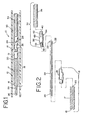
- Fig. 1 shows a deployment system 10 which includes an elongated flexible delivery catheter 12 which can be inserted into the vasculature of a patient and used to guide a deployment unit, generally designated at 14, to a preselected site in a manner generally known in the art.
- a deployment unit generally designated at 14
- the delivery catheter 12 and the deployment unit 14 are much longer than illustrated in the figures.
- the deployment unit 14 includes an elongated flexible pusher 16 which can be comprised of a delivery tube 17 and a pusher headpiece 19.
- the delivery tube 17 has a proximal end portion 18 and a distal end portion 20.
- An internal lumen (not shown) extends from the proximal end portion 18 of the delivery tube 17 through the pusher headpiece 19.
- the delivery tube 17 can be any suitable type of delivery tube generally known in the art that has sufficient column strength to push an embolic device through a delivery catheter and sufficient flexibility to be guided through tortuous pathways within the vasculature of a patient.
- the delivery tube preferably has the ability to resist torque applied to the delivery tube during release of the embolic device, as describe below.
- the delivery tube can be comprised a coil wound wire, or the delivery tube can be a flexible polymer sheath.
- An elongated member 24 is slidably disposed within the channel of the pusher 16, i.e., the elongated member 24 is relatively moveable in a proximal and a distal direction with respect to the pusher 16. Additionally, the elongated member 24 and the pusher 16 are able to rotate with respect to one another, i.e., the elongated member 24 is able to rotate within the channel of the pusher 16 and the pusher is able to rotate around the elongated member 24.
- the elongated member 24 is preferably comprised of a metallic or polymeric material which has tensile and flex properties that allow the elongated member to be easily guided through tortuous paths within the patient.
- the elongated member 24 includes a proximal end portion 26 and a distal end portion 28.
- the distal end portion 28 can be positioned to extend out of the pusher headpiece 19.
- the elongated member 24 also includes a connecting projection, cam follower or plug 29 extending in a generally radial direction from the distal end portion 28 of the elongated member 24.
- the connecting projection, cam follower or plug 29 is perpendicular to the axis of the elongated member 24.
- the connecting projection, cam follower or plug 29 can be used to removably secure an embolic device 30 to the elongated member 24, as described in more detail below.
- the elongated member 24 and the connecting projection, cam follower or plug 29 can be of a unitary construction.
- the projection, cam follower or plug 29 can be formed as a distal bend of the elongated member 24 which may have a modified characteristic such as an end of a different size.
- the connecting projection, cam follower or plug 29 can be attached to the elongated member 24 by any suitable attachment method known in the art, such as welding, force fitting, soldering or adhering with adhesive.
- the embolic device 30 is preferably an embolic device assembly that includes an embolic element 34 and a headpiece 36. As illustrated in Figs. 2 , 3 and 3a , the embolic device headpiece 36 has a proximal end portion 38 and a distal end portion 40. The distal end portion 40 includes a joining element 42, which is illustratively shown as a cylindrical projection, for connecting the embolic element 34 to the headpiece 36.
- the embolic element 34 and joining element 42 may be connected by weld, solder, adhesive or any other suitable attachment method known in the art.
- the embolic device 30 comprises the headpiece 36 and the embolic element 34 which are separate components that are secured together; however, it will be understood by one of ordinary skill in the art that the embolic element 34 and the headpiece 36 can be of a unitary construction to form embolic device 30.
- the embolic element 34 is preferably an embolic coil which can be of the type which takes a substantially linear configuration for being advanced through the delivery catheter and a randomly oriented relaxed condition after it is released from the catheter.
- the embolic element 34 may be any other type of embolic element which may take on various forms and configurations, such as hydrogels, foams, bioactive coils, braids, cables and hybrid devices.
- the headpiece 36 includes a circumferential wall 44 which defines a cavity 46.
- the circumferential wall 44 also includes a channel or cam pathway 48 into which the connecting projection, cam follower or plug 29 of the elongated member 24 can be threaded to secure the embolic device 30 to the elongated member 24.
- the channel or cam pathway 48 extends through the circumferential wall 44. It is also contemplated that the channel or cam pathway 48 could be comprised of a groove located on the inner surface of circumferential wall, but does not extend through the circumferential wall. Additionally, the channel or cam pathway 48 is preferably configured in the illustrated helical configuration; however, it is contemplated that the channel or cam pathway 48 can be of a substantially circular configuration or other turn configuration.
- the channel or cam pathway 48 includes an entrance 50 which can include a notch 52 that is sized to accommodate movement of the connecting projection, cam follower or plug 29 along it.
- the notch 52 can be slightly larger than the approximate dimensions of the connecting projection, cam follower or plug 29.
- the notch 52 aids in advancing the connecting projection, cam follower or plug 29 into the channel or cam pathway 48 and withdrawing the connecting projection, cam follower or plug 29 from the channel or cam pathway 48 when the headpiece 36 is engaged with headpiece 19.
- the channel or cam pathway 48 also includes an end wall 54 which is located distally of the entrance 50.
- the connecting projection, cam follower or plug 29 is positioned within the notch 52 of the entrance 54 of the channel or cam pathway 48.
- the elongated member 24 is then rotated to thread the connecting member, cam follower or plug 29 into the channel or cam pathway 48.
- the elongated member 24 is rotated in a clockwise direction to thread the connecting projection, cam follower or plug 29 into the channel or cam pathway 48 (if the helical configuration of the channel is wound in the opposite direction, the elongated member would be rotated counterclockwise to thread the connecting projection).
- the proximal end portion 38 of the headpiece 36 includes an arrangement for positively engaging the pusher, typically a headpiece thereof. By such an engagement, the embolic device headpiece and the pusher headpiece will not rotate circumferentially in a manner independent of each other.
- a preferred engagement arrangement in this regard includes an engagement member 56 of the headpiece 36 which mates with a corresponding engagement member 58 of a pusher headpiece 19.
- the illustrated respective engagement members 56, 58 each embody a partial circumferential projection in the axial direction, and such projections contact one another and can be complementary with each other.
- the projections combine to form a circumference with engaging surfaces that contact one another.
- the projections combine to form a shape having an axial or central axis, such as a cylinder.
- the engagement surfaces 62, 62a and 64, 64a can be along an axis aligned parallel to the central axis of the cylinder formed by the mated engagement members 56, 58.
- the engaging surfaces also need not be parallel to the central axis but can be at an acute angle to the central axis of the cylinder.
- each engagement surface can be along a common plane that is parallel to the central axis of the cylinder.
- the engagement surfaces of each headpiece can be along separate planes that do not intersect.
- each engagement surface could be along a different plane wherein each plane is separated by a distance. This would also include engagement surfaces of the same headpiece that are bevelled in the same direction at the same angle.
- the engagement surfaces can be along separate planes that intersect.
- the engagement surfaces 62, 62a of the headpiece 36 could be bevelled inwardly toward each other, or the engagement surfaces could be bevelled outwardly away from each other.
- the engagement surfaces typically can be planar, or flat, but can have a curved configuration or component.
- the engagement surfaces could have a tongue and groove mating configuration wherein an engagement surface of one headpiece could have a tongue, and the corresponding engagement surface of the other headpiece could have a corresponding groove which mates with the tongue when the engagement members are engaged.
- the engagement surfaces interact with each other to provide interference with independent circumferential movement of the headpieces while allowing independent movement of the embolic device 30 and the pusher 16 axially when it is desired to deploy the embolic device.
- the illustrated engagement member 56 of the embolic device headpiece 36 is a semi-circular projection 60 which includes engagement surfaces that are flats 62, 62a located on either side or edge of the projection 60.
- the flats 62, 62a in this illustrated embodiment engage corresponding engagement surfaces, such as flats 64, 64a, located on a semi-circular projection 66 of engagement member 58 of the pusher headpiece 19 shown in Figs. 4 and 4a .
- the arrangement for positively engaging the respective headpieces 19 and 36 functions as follows according to the illustrated preferred embodiment.
- the pusher headpiece 19 and the embolic device headpiece 36 engage each other to either resist or counteract torque applied to the proximal end portion 26 of the elongated member 24.
- the engagement of pusher headpiece 19 and embolic headpiece 36 can be used to rotate embolic device 30 by rotating pusher 16.
- the illustrated pusher headpiece 19 also includes a proximal end portion 68.
- the proximal end portion 68 includes a joining element 70, which is illustratively shown as a tubular projection, for joining the headpiece 19 to the delivery tube 17.
- the distal end portion 20 of the delivery tube 17 engages, such as by fitting over, the joining member 70.
- the joining member 70 and the delivery tube 17 can be connected by weld, solder, adhesive or any other suitable method.
- the headpiece 19 also includes a passageway 72 which allows the elongated member 24 to extend through it and project from headpiece 19 of the pusher 16.
- the embolic device 30 is preferably attached to the elongated member 24 of the pusher 16 by contacting the engagement member 56 of the embolic device 30 with engagement member 58 of the pusher 16 so that the flats or engagement surfaces 62, 62a and 64, 64a respectively of the respective engagement members 56 and 58 mate with each other.
- the elongated member 24 is then advanced distally within the pusher 16, and the connecting projection, cam follower or plug 29 is aligned with the notch 52 of the channel or cam pathway 48.
- the elongated member 24 is rotated in a direction that moves the connecting projection, cam follower or plug 29 within the channel or cam pathway 48.
- the elongated member 24 is rotated until the connecting projection, cam follower or plug 29 contacts the end wall 54 of the channel or cam pathway 48.
- An alternative method of connecting the embolic device 30 to the elongate member 24 would be to position the elongated member 24 so that it extends out of the headpiece 19 of the pusher 16. The distal end portion 28 of the elongated member 24 is then positioned so that the connecting projection, cam follower or plug 29 is located at the notch 52 of the channel or cam pathway 48. The embolic device 30 is maintained in a substantially stationary position, such as by grasping by hand or by some other mechanism, and the elongated member 24 is rotated to move the connecting projection, cam follower or plug 29 into the channel or cam pathway 48.
- the elongated member 24 can be maintained in a stationary position, and the embolic device 30 can be rotated by hand or some other method to position the connecting projection, cam follower or plug 29 into the channel or cam pathway 48.
- the delivery catheter 12 can be inserted into the vasculature system of a patient, and the distal end portion 74 of the catheter 12 can be positioned at a preselected location within a blood vessel, typically in conjunction with other devices and professional procedures as generally known in the art.
- the delivery unit 14 is inserted into a proximal end portion 76 of the catheter 12, and preferably the delivery unit 14 is advanced through the delivery catheter 12 until the embolic device 30 reaches the distal end portion 74 of the delivery catheter 12. If desired, the pusher headpiece 19 and the embolic device headpiece 36 can be engaged to increase column strength during the advancement of the pusher 16.
- the embolic device 30 may be moved out of the distal end portion 74 of the delivery catheter 12 in one of several ways.
- the delivery catheter 12 may be moved in a retrograde manner as indicated by arrow A.
- the pusher 16 may be advanced as indicated by arrow B.
- the embolic device 30 may be advanced out of the delivery catheter 12 by advancing the elongated member 24 in a distal direction.
- Yet another alternative can be to use any of the above methods in conjunction with one another.
- the embolic device 30 preferably includes a radiopaque marker so that the position of the embolic device 30 can be monitored by fluoroscopy.
- the elongated member 24 can be manipulated to more precisely place the embolic device 30 at the desired location. If it is determined that the embolic device 30 is in the wrong position and/or a different embolic device is required, the pusher 16 and the elongated member 24 can be retracted to move the embolic device 30 back into the delivery catheter 12. Once in the delivery catheter 12, the embolic device 30 can be repositioned or completely removed from the patient.
- the headpieces are so engaged.
- the pusher headpiece 19 is engaged with the embolic device headpiece 36 so that the corresponding flats 62, 62a and 64, 64a engage each other, as illustrated in Fig. 7 .
- Engagement of the headpieces 19 and 36 can be accomplished as needed by advancing the pusher 16 in a distal direction as indicated by arrow C. It is also contemplated that in certain situations, it may be advantageous to engage the headpieces 19 and 36 by moving the elongated member 24 in a proximal direction as indicated by arrow D.
- the embolic device 30 can be released by rotating the elongated member 24 so that the connecting projection, cam follower or plug 29 disengages and clears the channel or cam pathway 48.
- the connecting projection, cam follower or plug 29 is unthreaded from the channel or cam pathway 48 by rotating the elongated member 24 circumferentially to provide torsional force to the elongated member, as illustrated by arrow E (or in the opposite circumferential direction if the channel or cam pathway is helically wound in the opposite direction).
- the torque applied to the elongated member 24 is resisted by the delivery tube 17 and headpiece 19.
- the engagement along the headpieces 36 and 19, limits or reduces rotational movement of the headpiece 36 of the embolic device 30 which causes the connecting projection, cam follower or plug 29 to unthread from channel or cam pathway 48 of the substantially stationary headpiece 36.
- the headpieces 36 and 19 maintain contact during release of the embolic device 30.
- the engagement between the headpieces 36 and 19 also limits or reduces any undesired rotational movement of the embolic device 30.
- the channel or cam pathway 48 of the embolic headpiece 36 be configured so that the elongated member 24 is rotated in a direction opposite of the wind of the coil during unthreading to avoid buckling or kinking the pusher 16.
- the embolic device 30 can be released for deployment at a desired location within the patient such as within or at an aneurysm.
- the pusher 16 can now be retracted through the delivery catheter 12 and removed from the patient.
Description
- The present invention is related to the delivery of embolic occlusion devices. Disclosed are occlusion device deployment systems and methods for mechanically deploying occlusion devices at a preselected location within a patient, in an accurate and rapid manner. The deployment systems and methods are particularly suited for deploying an embolic coil at a location of concern within the vasculature of a patient.
- The use of catheter delivery systems for positioning and deploying therapeutic devices, such as dilation balloons, stents and embolic coils, in the vasculature of the human body has become a standard procedure for treating endovascular diseases. It has been found that such devices are particularly useful in treating areas where traditional operational procedures are impossible or pose a great risk to the patient, for example in the treatment of aneurysms in cranial blood vessels. Due to the delicate tissue surrounding cranial blood vessels, especially for example brain tissue, it is very difficult and often risky to perform surgical procedures to treat defects of the cranial blood vessels. Advancements in catheter deployment systems have provided an alternative treatment in such cases. Some of the advantages of catheter delivery systems are that they provide methods for treating blood vessels by an approach that has been found to reduce the risk of trauma to the surrounding tissue, and they also allow for treatment of blood vessels that in the past would have been considered inoperable.
- Typically, these procedures involve inserting the distal end of a delivery catheter into the vasculature of a patient and guiding it through the vasculature to a predetermined delivery site. A vascular occlusion device, such as an embolic coil, is attached to the end of a delivery member which pushes the coil through the catheter and out of the distal end of the catheter into the delivery site. Some of the problems that have been associated with these procedures relate to the accuracy of coil placement. For example, the force of the coil exiting the delivery catheter may cause the coil to over shoot the predetermined site or dislodge previously deployed coils. Also, once the coil is pushed out of the distal end of the catheter, the coil cannot be retracted and may migrate to an undesired location. Often, retrieving and repositioning the coil requires a separate procedure and has the potential to expose the patient to additional risk.
- In response to the above mentioned concerns, numerous devices and release mechanisms have been developed in an attempt to provide a deployment system which allows control of the occlusion device after the device has been delivered by the catheter and to also provide a rapid release or detachment mechanism to release the device once it is in place. One such device, which is disclosed in
US-5108407 , includes a fibre optic cable including a connector device mounted to the end to the optic fibre. An embolic coil is attached to the connector device by a heat releasable adhesive. Laser light is transmitted through the fibre optic cable to increase the temperature of the connector device, which melts the adhesive and releases the embolic coil. One drawback to using this type of system is the potential risk of melted adhesives contaminating the blood stream. - Another coil deployment system employs a pusher member having an embolic coil attached to the pusher member by a connector fibre which is capable of being broken by heat, is disclosed in
US-6478773 . The pusher member of this arrangement includes an electrical resistance heating coil through which the connector fibre is passed. Electrical current is supplied to the heating coil by a power source connected to the heating coil via wires extending through an internal lumen of the pusher. The power source is activated to increase the temperature of the heating coil which breaks the connector fibre. One drawback is that connecting the resistance heating coil to the power source requires running multiple wires through the pusher member. Additionally, the electrical current travelling through the wires may create stray electromagnetic fields that have the potential to interfere with other surgical and monitoring equipment. - Yet another embolic coil positioning and delivery system, which is described in
US-5989242 , includes catheter having a shape memory alloy connector attached to the distal end of the catheter. The connector includes a socket having a pair of spaced-apart fingers which are responsive to a change in temperature. The fingers are bent towards each other and hold a ball which is connected to an end of an embolic coil. The connector absorbs laser light transmitted through an optical cable and transforms the light into heat energy. The heat energy raises the temperature of the connector and opens the fingers, thereby releasing the embolic coil. This type of ball and socket connection is rigid and causes the catheter to be stiff, making it difficult to guide the catheter through the vasculature of the body. - A pusher-vasoocclusive coil assembly is described in
WO 93/11825 - Therefore, a need remains for a rapid release vascular occlusion deployment system or method that can function without electrical equipment or a power supply, does not develop chemical debris, is simple to manufacture, flexible and easy to guide through the vasculature of the body, provides excellent control over the occlusion device, and reduces the possibility of interference with other surgical and/or monitoring equipment.
- The present invention embodies deployment systems and methods for accurately and rapidly deploying a vascular occlusion device at a location of concern within the vasculature of a patient. The deployment system can employ an elongated flexible delivery catheter for guiding a deployment unit to a location of concern within a patient. The deployment unit includes a pusher for pushing and guiding the vascular occlusion device, such as an embolic coil, through the delivery catheter to the location of concern.
- Preferably, the pusher has a proximal end portion and a distal end portion, and a channel extending between the proximal end portion and the distal end portion. The pusher also includes an elongated member which is slidably located within the channel. The elongate member and the pusher are also able to rotate with respect to one another, i.e., the elongated member is able to rotate within the channel of the pusher, and the pusher is able to rotate around the elongated member.
- The distal end portion of the elongated member includes a connecting projection, plug or cam follower extending in a generally radial direction therefrom. An embolic device can be removably secured to the elongated member by engaging the connecting projection or cam follower with a channel or cam pathway defined by a proximal end portion of the embolic device. The connecting projection or cam follower can be engaged with the channel or cam pathway by positioning the elongated member so that the connecting projection or cam follower is at the entrance of the channel or cam pathway. The elongated member is rotated in the direction of the pathway, such as the wind, of the channel so that the connecting projection or cam follower moves within the channel or cam pathway. In one preferred embodiment, the channel or cam pathway is helically configured so that as the connecting projection or cam follower is helically threaded into the channel or cam pathway, the elongated member advances distally with respect to the embolic device and/or the embolic device advances proximally with respect to the elongated member.
- The embolic device can be released from the pusher after the device is positioned endoluminally. Prior to release, the distal end portion of the pusher is contacted with the proximal end portion of the embolic device attached to the elongated member so that the embolic device will not rotate independently of the pusher. This imparts an engaged state at which the embolic device is maintained in a substantially stationary position by engagement between the pusher and the embolic device. While in this engaged state, the elongated member is rotated in a direction opposite to the direction in which the elongated member had been rotated in order to secure the embolic device to the elongated member. The connecting projection or cam follower again moves along the channel or cam pathway until release, such as by unthreading the connecting projection or cam follower. The embolic device is thereby released from the deployment system at a desired deployment location.
- The device of the invention can be used in method of employing a pusher to deliver an embolic device to a location within the vasculature of a patient, the pusher including an elongated member having a proximal end portion, a distal end portion and a connecting projection along the distal end portion, the connecting projection being engageable with a pathway of an embolic device to removably attach the embolic device to the elongated member, comprising:
- manipulating the pusher and guiding the embolic device to a preselected location within the vasculature of a patient;
- maintaining the embolic device in a substantially stationary position; and
- disengaging the connecting projection by rotating the elongated member, thereby releasing the embolic device from the pusher.
- The device of the invention can be used in a method of employing a pusher to deliver an embolic device to a location within the vasculature of a patient, the pusher including an elongated member having a proximal end portion, a distal end portion and a connecting projection along the distal end portion, the connecting projection being threadably engageable with a channel of an embolic device to removably attach the embolic device to the elongated member, comprising:
- manipulating the pusher and guiding the embolic device to a preselected location within the vasculature of a patient;
- maintaining the elongated member in a substantially stationary position; and
- unthreading the connecting projection by rotating the embolic device, thereby releasing the embolic device from the pusher to deploy the embolic device within the vasculature.
- Embodiments of the invention will now be described by way of example with reference to the accompanying drawings, in which:
-
Fig. 1 is an enlarged partially sectioned view of an occlusion device deployment system in accordance with a preferred embodiment of the present invention; -
Fig. 2 is an exploded view of the deployment unit illustrated inFig. 1 ; -
Figs. 3 and 3a are enlarged perspective views of one embodiment of the embolic device headpiece; -
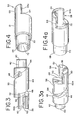
Figs. 4 and 4a are enlarged perspective views of one embodiment of the pusher headpiece; -
Fig. 5 is an enlarged partially sectioned view of the deployment system ofFig. 1 shown prior to deployment; -
Fig. 6 is an enlarged partially sectioned view of the deployment system ofFig. 1 shown after the embolic device has exited the delivery catheter and shown with the distal end portion of the pusher and the embolic device being separated; -
Fig. 7 is an enlarged partially sectioned view of the deployment system ofFig. 1 shown with the pusher engaging the embolic device after the embolic device has exited the delivery catheter; and -
Fig. 8 is an enlarged partially sectioned view of the deployment system ofFig. 1 shown after the embolic device has been released. - Referring to the drawings,
Fig. 1 shows a deployment system 10 which includes an elongatedflexible delivery catheter 12 which can be inserted into the vasculature of a patient and used to guide a deployment unit, generally designated at 14, to a preselected site in a manner generally known in the art. One of ordinary skill in the art will appreciate that thedelivery catheter 12 and thedeployment unit 14 are much longer than illustrated in the figures. - Referring to
Figs. 1 and 2 , thedeployment unit 14 includes an elongatedflexible pusher 16 which can be comprised of adelivery tube 17 and apusher headpiece 19. Thedelivery tube 17 has aproximal end portion 18 and adistal end portion 20. An internal lumen (not shown) extends from theproximal end portion 18 of thedelivery tube 17 through thepusher headpiece 19. Thedelivery tube 17 can be any suitable type of delivery tube generally known in the art that has sufficient column strength to push an embolic device through a delivery catheter and sufficient flexibility to be guided through tortuous pathways within the vasculature of a patient. Additionally, the delivery tube preferably has the ability to resist torque applied to the delivery tube during release of the embolic device, as describe below. For example, the delivery tube can be comprised a coil wound wire, or the delivery tube can be a flexible polymer sheath. - An
elongated member 24 is slidably disposed within the channel of thepusher 16, i.e., theelongated member 24 is relatively moveable in a proximal and a distal direction with respect to thepusher 16. Additionally, theelongated member 24 and thepusher 16 are able to rotate with respect to one another, i.e., theelongated member 24 is able to rotate within the channel of thepusher 16 and the pusher is able to rotate around theelongated member 24. - The
elongated member 24 is preferably comprised of a metallic or polymeric material which has tensile and flex properties that allow the elongated member to be easily guided through tortuous paths within the patient. - The
elongated member 24 includes aproximal end portion 26 and adistal end portion 28. Thedistal end portion 28 can be positioned to extend out of thepusher headpiece 19. Theelongated member 24 also includes a connecting projection, cam follower or plug 29 extending in a generally radial direction from thedistal end portion 28 of theelongated member 24. In the illustrated arrangement, the connecting projection, cam follower or plug 29 is perpendicular to the axis of theelongated member 24. The connecting projection, cam follower or plug 29 can be used to removably secure anembolic device 30 to theelongated member 24, as described in more detail below. - The
elongated member 24 and the connecting projection, cam follower or plug 29 can be of a unitary construction. For example the projection, cam follower or plug 29 can be formed as a distal bend of theelongated member 24 which may have a modified characteristic such as an end of a different size. Alternatively, the connecting projection, cam follower or plug 29 can be attached to theelongated member 24 by any suitable attachment method known in the art, such as welding, force fitting, soldering or adhering with adhesive. - The
embolic device 30 is preferably an embolic device assembly that includes anembolic element 34 and aheadpiece 36. As illustrated inFigs. 2 ,3 and 3a , theembolic device headpiece 36 has aproximal end portion 38 and adistal end portion 40. Thedistal end portion 40 includes a joiningelement 42, which is illustratively shown as a cylindrical projection, for connecting theembolic element 34 to theheadpiece 36. Theembolic element 34 and joiningelement 42 may be connected by weld, solder, adhesive or any other suitable attachment method known in the art. Illustratively, theembolic device 30 comprises theheadpiece 36 and theembolic element 34 which are separate components that are secured together; however, it will be understood by one of ordinary skill in the art that theembolic element 34 and theheadpiece 36 can be of a unitary construction to formembolic device 30. - The
embolic element 34 is preferably an embolic coil which can be of the type which takes a substantially linear configuration for being advanced through the delivery catheter and a randomly oriented relaxed condition after it is released from the catheter. Alternatively, theembolic element 34 may be any other type of embolic element which may take on various forms and configurations, such as hydrogels, foams, bioactive coils, braids, cables and hybrid devices. - In the illustrated embodiment, the
headpiece 36 includes acircumferential wall 44 which defines acavity 46. Thecircumferential wall 44 also includes a channel orcam pathway 48 into which the connecting projection, cam follower or plug 29 of theelongated member 24 can be threaded to secure theembolic device 30 to theelongated member 24. Illustratively, the channel orcam pathway 48 extends through thecircumferential wall 44. It is also contemplated that the channel orcam pathway 48 could be comprised of a groove located on the inner surface of circumferential wall, but does not extend through the circumferential wall. Additionally, the channel orcam pathway 48 is preferably configured in the illustrated helical configuration; however, it is contemplated that the channel orcam pathway 48 can be of a substantially circular configuration or other turn configuration. - Preferably, including when the channel or
cam pathway 48 is of a helical configuration, the channel orcam pathway 48 includes anentrance 50 which can include anotch 52 that is sized to accommodate movement of the connecting projection, cam follower or plug 29 along it. For example, thenotch 52 can be slightly larger than the approximate dimensions of the connecting projection, cam follower or plug 29. Thenotch 52 aids in advancing the connecting projection, cam follower or plug 29 into the channel orcam pathway 48 and withdrawing the connecting projection, cam follower or plug 29 from the channel orcam pathway 48 when theheadpiece 36 is engaged withheadpiece 19. The channel orcam pathway 48 also includes anend wall 54 which is located distally of theentrance 50. - To connect the
embolic device 30 to theelongated member 24, the connecting projection, cam follower or plug 29 is positioned within thenotch 52 of theentrance 54 of the channel orcam pathway 48. Theelongated member 24 is then rotated to thread the connecting member, cam follower or plug 29 into the channel orcam pathway 48. In the illustrated embodiment, theelongated member 24 is rotated in a clockwise direction to thread the connecting projection, cam follower or plug 29 into the channel or cam pathway 48 (if the helical configuration of the channel is wound in the opposite direction, the elongated member would be rotated counterclockwise to thread the connecting projection). When the connecting projection, cam follower or plug 29 is threaded in a helically shaped channel orcam pathway 48, theelongated member 24 moves distally within thecavity 46 of theheadpiece 36. The elongated member is rotated until the connecting projection, cam follower or plug 29 contacts endwall 54 of the channel orcam pathway 48 and is thus set into a closed condition. - The
proximal end portion 38 of theheadpiece 36 includes an arrangement for positively engaging the pusher, typically a headpiece thereof. By such an engagement, the embolic device headpiece and the pusher headpiece will not rotate circumferentially in a manner independent of each other. - A preferred engagement arrangement in this regard includes an
engagement member 56 of theheadpiece 36 which mates with acorresponding engagement member 58 of apusher headpiece 19. As shown inFigs. 3, 3a, 4 and 4a , the illustratedrespective engagement members - The engagement surfaces 62, 62a and 64, 64a can be along an axis aligned parallel to the central axis of the cylinder formed by the mated
engagement members - In yet another alternative, the engagement surfaces can be along separate planes that intersect. For example, in the illustrated embodiment the engagement surfaces 62, 62a of the
headpiece 36 could be bevelled inwardly toward each other, or the engagement surfaces could be bevelled outwardly away from each other. The engagement surfaces typically can be planar, or flat, but can have a curved configuration or component. For example, the engagement surfaces could have a tongue and groove mating configuration wherein an engagement surface of one headpiece could have a tongue, and the corresponding engagement surface of the other headpiece could have a corresponding groove which mates with the tongue when the engagement members are engaged. - The engagement surfaces interact with each other to provide interference with independent circumferential movement of the headpieces while allowing independent movement of the
embolic device 30 and thepusher 16 axially when it is desired to deploy the embolic device. The illustratedengagement member 56 of theembolic device headpiece 36 is asemi-circular projection 60 which includes engagement surfaces that areflats projection 60. Theflats flats semi-circular projection 66 ofengagement member 58 of thepusher headpiece 19 shown inFigs. 4 and 4a . - As will be explained in more detail below, the arrangement for positively engaging the
respective headpieces pusher headpiece 19 and theembolic device headpiece 36 engage each other to either resist or counteract torque applied to theproximal end portion 26 of theelongated member 24. Alternatively, the engagement ofpusher headpiece 19 andembolic headpiece 36 can be used to rotateembolic device 30 by rotatingpusher 16. - As illustrated in
Figs. 4 and 4a , the illustratedpusher headpiece 19 also includes aproximal end portion 68. Theproximal end portion 68 includes a joiningelement 70, which is illustratively shown as a tubular projection, for joining theheadpiece 19 to thedelivery tube 17. Thedistal end portion 20 of thedelivery tube 17 engages, such as by fitting over, the joiningmember 70. The joiningmember 70 and thedelivery tube 17 can be connected by weld, solder, adhesive or any other suitable method. Theheadpiece 19 also includes apassageway 72 which allows theelongated member 24 to extend through it and project fromheadpiece 19 of thepusher 16. - To secure the embolic device in the vascular occlusion deployment system, the
embolic device 30 is preferably attached to theelongated member 24 of thepusher 16 by contacting theengagement member 56 of theembolic device 30 withengagement member 58 of thepusher 16 so that the flats or engagement surfaces 62, 62a and 64, 64a respectively of therespective engagement members elongated member 24 is then advanced distally within thepusher 16, and the connecting projection, cam follower or plug 29 is aligned with thenotch 52 of the channel orcam pathway 48. Theelongated member 24 is rotated in a direction that moves the connecting projection, cam follower or plug 29 within the channel orcam pathway 48. Theelongated member 24 is rotated until the connecting projection, cam follower or plug 29 contacts theend wall 54 of the channel orcam pathway 48. - An alternative method of connecting the
embolic device 30 to theelongate member 24 would be to position theelongated member 24 so that it extends out of theheadpiece 19 of thepusher 16. Thedistal end portion 28 of theelongated member 24 is then positioned so that the connecting projection, cam follower or plug 29 is located at thenotch 52 of the channel orcam pathway 48. Theembolic device 30 is maintained in a substantially stationary position, such as by grasping by hand or by some other mechanism, and theelongated member 24 is rotated to move the connecting projection, cam follower or plug 29 into the channel orcam pathway 48. In lieu of rotating theelongated member 24, theelongated member 24 can be maintained in a stationary position, and theembolic device 30 can be rotated by hand or some other method to position the connecting projection, cam follower or plug 29 into the channel orcam pathway 48. - After the
embolic device 30 has been attached to theelongated member 24, referring toFigs. 5 to 8 , thedelivery catheter 12 can be inserted into the vasculature system of a patient, and thedistal end portion 74 of thecatheter 12 can be positioned at a preselected location within a blood vessel, typically in conjunction with other devices and professional procedures as generally known in the art. Thedelivery unit 14 is inserted into aproximal end portion 76 of thecatheter 12, and preferably thedelivery unit 14 is advanced through thedelivery catheter 12 until theembolic device 30 reaches thedistal end portion 74 of thedelivery catheter 12. If desired, thepusher headpiece 19 and theembolic device headpiece 36 can be engaged to increase column strength during the advancement of thepusher 16. - Once the
embolic device 30 reaches thedistal end portion 74 of thedelivery catheter 12, theembolic device 30 may be moved out of thedistal end portion 74 of thedelivery catheter 12 in one of several ways. Thedelivery catheter 12 may be moved in a retrograde manner as indicated by arrow A. Alternatively, thepusher 16 may be advanced as indicated by arrow B. As a further alternative, theembolic device 30 may be advanced out of thedelivery catheter 12 by advancing theelongated member 24 in a distal direction. Yet another alternative can be to use any of the above methods in conjunction with one another. - The
embolic device 30 preferably includes a radiopaque marker so that the position of theembolic device 30 can be monitored by fluoroscopy. Referring toFig. 6 , after theembolic device 30 has exited thedelivery catheter 12, if required, theelongated member 24 can be manipulated to more precisely place theembolic device 30 at the desired location. If it is determined that theembolic device 30 is in the wrong position and/or a different embolic device is required, thepusher 16 and theelongated member 24 can be retracted to move theembolic device 30 back into thedelivery catheter 12. Once in thedelivery catheter 12, theembolic device 30 can be repositioned or completely removed from the patient. - After it has been determined that the
embolic device 30 is at the desired location within the patient, and if not already in engagement, the headpieces are so engaged. Typically, thepusher headpiece 19 is engaged with theembolic device headpiece 36 so that the correspondingflats Fig. 7 . Engagement of theheadpieces pusher 16 in a distal direction as indicated by arrow C. It is also contemplated that in certain situations, it may be advantageous to engage theheadpieces elongated member 24 in a proximal direction as indicated by arrow D. - After the
headpieces embolic device 30 can be released by rotating theelongated member 24 so that the connecting projection, cam follower or plug 29 disengages and clears the channel orcam pathway 48. Preferably, the connecting projection, cam follower or plug 29 is unthreaded from the channel orcam pathway 48 by rotating theelongated member 24 circumferentially to provide torsional force to the elongated member, as illustrated by arrow E (or in the opposite circumferential direction if the channel or cam pathway is helically wound in the opposite direction). The torque applied to theelongated member 24 is resisted by thedelivery tube 17 andheadpiece 19. Additionally, the engagement along theheadpieces flats headpiece 36 of theembolic device 30 which causes the connecting projection, cam follower or plug 29 to unthread from channel orcam pathway 48 of the substantiallystationary headpiece 36. Theheadpieces embolic device 30. The engagement between theheadpieces embolic device 30. When thepusher 16 is comprised of a coiled wire, it is preferable that the channel orcam pathway 48 of theembolic headpiece 36 be configured so that theelongated member 24 is rotated in a direction opposite of the wind of the coil during unthreading to avoid buckling or kinking thepusher 16. - It is also contemplated that there may be situations where it would be advantageous to disengage the connecting projection, cam follower or plug 29 from the channel or
cam pathway 48 by rotating theembolic device 30 while maintaining theelongated member 24 in a substantially stationary position. By this approach, thepusher 16 is rotated and the rotational movement of thepusher 16 is translated along it, through the headpieces, to the embolic device. At the same time, the elongated member is maintained in a substantially stationary position, resulting in the unthreading in the connecting projection, cam follower or plug 29 from the channel orcam pathway 48. - As illustrated in
Fig. 8 , after the connecting projection, cam follower or plug 29 has been rotated and moved so as to clear the channel orcam pathway 48, theembolic device 30 can be released for deployment at a desired location within the patient such as within or at an aneurysm. Thepusher 16 can now be retracted through thedelivery catheter 12 and removed from the patient.
Claims (9)
- An embolic device delivery system (10), comprising:a pusher (16) having a proximal end portion and a distal end portion; ,an elongated member (24) having a proximal end portion (26) and a distal end portion (26), said elongated member positioned along the pusher (16), said elongated member and said pusher being relatively rotatable;a connecting projection (29) extending in a generally radial direction from the distal end portion of the elongated member (24), said connecting projection being in operative camming communication with a pathway of a proximal portion of an embolic device to removably secure the embolic device to the elongated member; andsaid distal end portion of the pusher contacting the embolic device (30) to essentially prevent rotational movement of the embolic device with respect to the pusher.
- The delivery system of claim 1, wherein the pathway of the embolic device (30) comprises a generally helical configuration.
- The delivery system of claim 1, wherein the distal end portion of the pusher (16), includes an engagement member (58) and the embolic device (30) includes an engagement member (56), and wherein the contacting of the distal end portion of the pusher and the embolic device to essentially prevent rotational movement of the embolic device comprises mating the engagement member of the pusher with the engagement member of the embolic device.
- The delivery system of claim 3, wherein:the engagement member (58) of the pusher (16) and the engagement member (56) of the embolic device (30) mate to form a shape having an axial axis;the engagement member of the pusher including at least one engagement surface that is axially oriented and extends in a direction that is generally parallel to the axial axis;the engagement member of the embolic device including at least one engagement surface (68) that is axially oriented and extends in a direction that is generally parallel to the axial axis; andthe at least one engagement surface (64) of the engagement member of the pusher contacting the at least one engagement surface of the engagement member of the embolic device when said engagement members mate.
- The delivery system of claim 4, wherein the at least one engagement surface of the engagement member (58) of the pusher (16) and the at least one engagement surface (62) of the engagement member (56) of the embolic device (30) are substantially planar.
- The delivery system of claim 3, wherein the pusher comprises a delivery tube (17) and a pusher headpiece (19), and the engagement member (58) of the pusher is located on the pusher (16) headpiece.
- The delivery system of claim 3, wherein the embolic device (30) comprises an embolic element (34) and an embolic device headpiece (36), and the engagement member (56) of the embolic device is located on the embolic device headpiece.
- The delivery system of claim 7, wherein the pathway is a threadable channel (48) of the embolic device headpiece (36).
- A kit which comprises an embolic device delivery system as claimed in claim 1, and an embolic device (30) which has a proximal end portion and a distal end portion, with a pathway provided in the proximal end portion, in which:the elongated member (24) includes a distal end portion which has a connecting projection (29) extending in a generally radial direction from the distal end portion of the elongated member, said connecting projection engaging the pathway to removably secure the embolic device to the elongated member; andthe distal end portion of the pusher (16) contacting the proximal end portion of the embolic device substantially to prevent rotation of the embolic device with respect to the pusher.
Applications Claiming Priority (1)
| Application Number | Priority Date | Filing Date | Title |
|---|---|---|---|
| US11/290,954 US20070123927A1 (en) | 2005-11-30 | 2005-11-30 | Embolic device delivery system |
Publications (2)
| Publication Number | Publication Date |
|---|---|
| EP1792575A1 EP1792575A1 (en) | 2007-06-06 |
| EP1792575B1 true EP1792575B1 (en) | 2010-06-30 |
Family
ID=37735217
Family Applications (1)
| Application Number | Title | Priority Date | Filing Date |
|---|---|---|---|
| EP06256106A Active EP1792575B1 (en) | 2005-11-30 | 2006-11-29 | Embolic device delivery system |
Country Status (4)
| Country | Link |
|---|---|
| US (1) | US20070123927A1 (en) |
| EP (1) | EP1792575B1 (en) |
| JP (1) | JP4884943B2 (en) |
| DE (1) | DE602006015148D1 (en) |
Cited By (3)
| Publication number | Priority date | Publication date | Assignee | Title |
|---|---|---|---|---|
| US8192480B2 (en) | 2007-12-21 | 2012-06-05 | Microvention, Inc. | System and method of detecting implant detachment |
| US8753303B2 (en) | 2009-09-25 | 2014-06-17 | Boston Scientific Scimed, Inc. | Delivery system having stent locking structure |
| US9242070B2 (en) | 2007-12-21 | 2016-01-26 | MicronVention, Inc. | System and method for locating detachment zone of a detachable implant |
Families Citing this family (20)
| Publication number | Priority date | Publication date | Assignee | Title |
|---|---|---|---|---|
| US20070135826A1 (en) | 2005-12-01 | 2007-06-14 | Steve Zaver | Method and apparatus for delivering an implant without bias to a left atrial appendage |
| US20070299461A1 (en) * | 2006-06-21 | 2007-12-27 | Boston Scientific Scimed, Inc. | Embolic coils and related components, systems, and methods |
| US20090099592A1 (en) * | 2007-10-15 | 2009-04-16 | Boston Scientific Scimed, Inc. | Detachable Interlock Systems and Methods of Use |
| CA2739603A1 (en) * | 2008-10-13 | 2010-04-22 | Stryker Corporation | Vaso-occlusive coil delivery system |
| CN102368962A (en) * | 2009-03-13 | 2012-03-07 | 斯瑞克公司 | Electrical contact for occlusive device delivery system |
| EP2416712B1 (en) | 2009-04-06 | 2018-12-19 | Stryker Corporation | Delivery wire for occlusive device delivery system |
| US8398671B2 (en) * | 2009-04-16 | 2013-03-19 | Stryker Corporation | Electrical contact for occlusive device delivery system |
| US9314250B2 (en) | 2009-04-16 | 2016-04-19 | Stryker Corporation | Electrical contact for occlusive device delivery system |
| WO2010120653A1 (en) * | 2009-04-16 | 2010-10-21 | Boston Scientific Scimed, Inc. | Delivery wire for occlusive device delivery system and method of manufacture |
| US8992563B2 (en) * | 2009-11-02 | 2015-03-31 | Boston Scientific Scimed, Inc. | Delivery wire assembly for occlusive device delivery system |
| WO2011062844A1 (en) * | 2009-11-18 | 2011-05-26 | Boston Scientific Scimed, Inc. | Delivery wire assembly for occlusive device delivery system |
| US8821529B2 (en) | 2011-03-25 | 2014-09-02 | Aga Medical Corporation | Device and method for occluding a septal defect |
| US10201336B2 (en) * | 2011-03-25 | 2019-02-12 | St. Jude Medical, Cardiology Division, Inc. | Device and method for delivering a vascular device |
| WO2014074132A1 (en) * | 2012-11-09 | 2014-05-15 | Aga Medical Corporation | Devices and methods for delivering vascular implants |
| US9788839B2 (en) * | 2014-02-14 | 2017-10-17 | Cook Medical Technologies Llc | Stable screw-type detachment mechanism |
| EP3445284B1 (en) * | 2016-04-21 | 2023-05-24 | Zenflow, Inc. | Systems for implants and deployment devices |
| CN106377292B (en) * | 2016-11-10 | 2024-04-12 | 通桥医疗科技有限公司 | Embolic coil release device |
| AU2017371223B2 (en) | 2016-12-09 | 2023-04-27 | Zenflow, Inc. | Systems, devices, and methods for the accurate deployment of an implant in the prostatic urethra |
| CN111741721B (en) * | 2018-02-23 | 2023-08-04 | 波士顿科学国际有限公司 | Attachment mechanism for medical implants |
| AU2021329380A1 (en) | 2020-08-21 | 2023-03-16 | Shape Memory Medical, Inc. | Mechanical detachment system for transcatheter devices |
Family Cites Families (38)
| Publication number | Priority date | Publication date | Assignee | Title |
|---|---|---|---|---|
| US3789841A (en) * | 1971-09-15 | 1974-02-05 | Becton Dickinson Co | Disposable guide wire |
| US3963322A (en) * | 1975-01-23 | 1976-06-15 | Ite Imperial Corporation | Torque controlling set screw for use with the cable of solderless connectors, or the like |
| US4884579A (en) * | 1988-04-18 | 1989-12-05 | Target Therapeutics | Catheter guide wire |
| US5108407A (en) * | 1990-06-08 | 1992-04-28 | Rush-Presbyterian St. Luke's Medical Center | Method and apparatus for placement of an embolic coil |
| US5234437A (en) * | 1991-12-12 | 1993-08-10 | Target Therapeutics, Inc. | Detachable pusher-vasoocclusion coil assembly with threaded coupling |
| US5261916A (en) * | 1991-12-12 | 1993-11-16 | Target Therapeutics | Detachable pusher-vasoocclusive coil assembly with interlocking ball and keyway coupling |
| US5263964A (en) * | 1992-05-06 | 1993-11-23 | Coil Partners Ltd. | Coaxial traction detachment apparatus and method |
| DE69327157T2 (en) * | 1992-09-22 | 2000-04-06 | Target Therapeutics Inc | ARRANGEMENT OF A DETACHABLE EMBOLY SPIRAL SPRING |
| US5250071A (en) * | 1992-09-22 | 1993-10-05 | Target Therapeutics, Inc. | Detachable embolic coil assembly using interlocking clasps and method of use |
| US5312415A (en) * | 1992-09-22 | 1994-05-17 | Target Therapeutics, Inc. | Assembly for placement of embolic coils using frictional placement |
| USRE37117E1 (en) * | 1992-09-22 | 2001-03-27 | Target Therapeutics, Inc. | Detachable embolic coil assembly using interlocking clasps and method of use |
| US5925059A (en) * | 1993-04-19 | 1999-07-20 | Target Therapeutics, Inc. | Detachable embolic coil assembly |
| US5725546A (en) * | 1994-06-24 | 1998-03-10 | Target Therapeutics, Inc. | Detachable microcoil delivery catheter |
| IL116561A0 (en) * | 1994-12-30 | 1996-03-31 | Target Therapeutics Inc | Severable joint for detachable devices placed within the body |
| US6705323B1 (en) * | 1995-06-07 | 2004-03-16 | Conceptus, Inc. | Contraceptive transcervical fallopian tube occlusion devices and methods |
| US5989242A (en) * | 1995-06-26 | 1999-11-23 | Trimedyne, Inc. | Therapeutic appliance releasing device |
| US5601600A (en) * | 1995-09-08 | 1997-02-11 | Conceptus, Inc. | Endoluminal coil delivery system having a mechanical release mechanism |
| US5984929A (en) * | 1997-08-29 | 1999-11-16 | Target Therapeutics, Inc. | Fast detaching electronically isolated implant |
| US6346091B1 (en) * | 1998-02-13 | 2002-02-12 | Stephen C. Jacobsen | Detachable coil for aneurysm therapy |
| US6478773B1 (en) * | 1998-12-21 | 2002-11-12 | Micrus Corporation | Apparatus for deployment of micro-coil using a catheter |
| US6296622B1 (en) * | 1998-12-21 | 2001-10-02 | Micrus Corporation | Endoluminal device delivery system using axially recovering shape memory material |
| US6277126B1 (en) * | 1998-10-05 | 2001-08-21 | Cordis Neurovascular Inc. | Heated vascular occlusion coil development system |
| US6102932A (en) * | 1998-12-15 | 2000-08-15 | Micrus Corporation | Intravascular device push wire delivery system |
| US6835185B2 (en) * | 1998-12-21 | 2004-12-28 | Micrus Corporation | Intravascular device deployment mechanism incorporating mechanical detachment |
| US6347333B2 (en) * | 1999-01-15 | 2002-02-12 | Unext.Com Llc | Online virtual campus |
| AU2001268587A1 (en) * | 2000-06-19 | 2002-01-02 | Image-Guided Neurologics, Inc. | System and method of minimally-invasive exovascular aneurysm treatment |
| US6566147B2 (en) * | 2001-02-02 | 2003-05-20 | Micron Technology, Inc. | Method for controlling deposition of dielectric films |
| US6811561B2 (en) * | 2001-11-15 | 2004-11-02 | Cordis Neurovascular, Inc. | Small diameter deployment system with improved headpiece |
| US7338511B2 (en) * | 2002-05-24 | 2008-03-04 | Boston Scientific-Scimed, Inc. | Solid embolic material with variable expansion |
| US7597704B2 (en) * | 2003-04-28 | 2009-10-06 | Atritech, Inc. | Left atrial appendage occlusion device with active expansion |
| US7735493B2 (en) * | 2003-08-15 | 2010-06-15 | Atritech, Inc. | System and method for delivering a left atrial appendage containment device |
| EP1691856A2 (en) * | 2003-10-14 | 2006-08-23 | Cube Medical A/S | Medical device with electrospun nanofibers |
| US8092483B2 (en) * | 2004-03-06 | 2012-01-10 | Medtronic, Inc. | Steerable device having a corewire within a tube and combination with a functional medical component |
| JP2008503254A (en) * | 2004-06-16 | 2008-02-07 | ヌームアールエックス・インコーポレーテッド | Intrabronchial lung volume reduction system |
| US7708755B2 (en) * | 2005-06-02 | 2010-05-04 | Codman & Shurtleff Inc. | Stretch resistant embolic coil delivery system with combined mechanical and pressure release mechanism |
| US7344558B2 (en) * | 2006-02-28 | 2008-03-18 | Cordis Development Corporation | Embolic device delivery system |
| US7766933B2 (en) * | 2006-03-31 | 2010-08-03 | Codman & Shurtleff, Inc. | Stretch resistant design for embolic coils with stabilization bead |
| US7771451B2 (en) * | 2006-04-05 | 2010-08-10 | Boston Scientific Scimed, Inc. | Method and apparatus for the deployment of vaso-occlusive coils |
-
2005
- 2005-11-30 US US11/290,954 patent/US20070123927A1/en not_active Abandoned
-
2006
- 2006-11-29 JP JP2006321935A patent/JP4884943B2/en active Active
- 2006-11-29 EP EP06256106A patent/EP1792575B1/en active Active
- 2006-11-29 DE DE602006015148T patent/DE602006015148D1/en active Active
Cited By (6)
| Publication number | Priority date | Publication date | Assignee | Title |
|---|---|---|---|---|
| US8192480B2 (en) | 2007-12-21 | 2012-06-05 | Microvention, Inc. | System and method of detecting implant detachment |
| US8460332B2 (en) | 2007-12-21 | 2013-06-11 | Microvention, Inc. | System and method of detecting implant detachment |
| US9242070B2 (en) | 2007-12-21 | 2016-01-26 | MicronVention, Inc. | System and method for locating detachment zone of a detachable implant |
| US10299755B2 (en) | 2007-12-21 | 2019-05-28 | Microvention, Inc. | System and method for locating detachment zone of a detachable implant |
| US8753303B2 (en) | 2009-09-25 | 2014-06-17 | Boston Scientific Scimed, Inc. | Delivery system having stent locking structure |
| US9597207B2 (en) | 2009-09-25 | 2017-03-21 | Boston Scientific Scimed, Inc. | Delivery system having stent locking structure |
Also Published As
| Publication number | Publication date |
|---|---|
| JP4884943B2 (en) | 2012-02-29 |
| DE602006015148D1 (en) | 2010-08-12 |
| EP1792575A1 (en) | 2007-06-06 |
| JP2007160086A (en) | 2007-06-28 |
| US20070123927A1 (en) | 2007-05-31 |
Similar Documents
| Publication | Publication Date | Title |
|---|---|---|
| EP1792575B1 (en) | Embolic device delivery system | |
| EP1792576B1 (en) | Embolic device delivery system | |
| US7344558B2 (en) | Embolic device delivery system | |
| EP1813213B1 (en) | Embolic device delivery system | |
| US8795316B2 (en) | Implantable medical device delivery system with a frangible portion and methods of making and using the same | |
| JP4662576B2 (en) | Removable vascular occlusion member using a thermoadhesive joint | |
| US5800455A (en) | Detachable embolic coil assembly | |
| EP0617632B1 (en) | Detachable embolic coil assembly | |
| US5925059A (en) | Detachable embolic coil assembly | |
| EP0914804B1 (en) | Detachable embolic coil assembly | |
| EP1738693B1 (en) | Laser-based vascular occlusion device detachment system | |
| US8721701B2 (en) | Vascular occlusion device deployment system with gripping feature opened by a collapsible reaction chamber | |
| CA2551328A1 (en) | Chemically based vascular occlusion device deployment with gripping feature | |
| CA2551374C (en) | Chemically based vascular occlusion device deployment |
Legal Events
| Date | Code | Title | Description |
|---|---|---|---|
| PUAI | Public reference made under article 153(3) epc to a published international application that has entered the european phase |
Free format text: ORIGINAL CODE: 0009012 |
|
| AK | Designated contracting states |
Kind code of ref document: A1 Designated state(s): AT BE BG CH CY CZ DE DK EE ES FI FR GB GR HU IE IS IT LI LT LU LV MC NL PL PT RO SE SI SK TR |
|
| AX | Request for extension of the european patent |
Extension state: AL BA HR MK YU |
|
| RIN1 | Information on inventor provided before grant (corrected) |
Inventor name: FARNAN, ROBERT C. |
|
| 17P | Request for examination filed |
Effective date: 20071126 |
|
| AKX | Designation fees paid |
Designated state(s): DE FR GB NL |
|
| GRAP | Despatch of communication of intention to grant a patent |
Free format text: ORIGINAL CODE: EPIDOSNIGR1 |
|
| RAP1 | Party data changed (applicant data changed or rights of an application transferred) |
Owner name: CODMAN & SHURTLEFF, INC. |
|
| GRAS | Grant fee paid |
Free format text: ORIGINAL CODE: EPIDOSNIGR3 |
|
| GRAA | (expected) grant |
Free format text: ORIGINAL CODE: 0009210 |
|
| AK | Designated contracting states |
Kind code of ref document: B1 Designated state(s): DE FR GB NL |
|
| REG | Reference to a national code |
Ref country code: GB Ref legal event code: FG4D |
|
| REF | Corresponds to: |
Ref document number: 602006015148 Country of ref document: DE Date of ref document: 20100812 Kind code of ref document: P |
|
| REG | Reference to a national code |
Ref country code: NL Ref legal event code: T3 |
|
| PLBE | No opposition filed within time limit |
Free format text: ORIGINAL CODE: 0009261 |
|
| STAA | Information on the status of an ep patent application or granted ep patent |
Free format text: STATUS: NO OPPOSITION FILED WITHIN TIME LIMIT |
|
| 26N | No opposition filed |
Effective date: 20110331 |
|
| REG | Reference to a national code |
Ref country code: DE Ref legal event code: R097 Ref document number: 602006015148 Country of ref document: DE Effective date: 20110330 |
|
| REG | Reference to a national code |
Ref country code: FR Ref legal event code: CA Effective date: 20111011 |
|
| REG | Reference to a national code |
Ref country code: FR Ref legal event code: PLFP Year of fee payment: 11 |
|
| REG | Reference to a national code |
Ref country code: FR Ref legal event code: PLFP Year of fee payment: 12 |
|
| REG | Reference to a national code |
Ref country code: FR Ref legal event code: PLFP Year of fee payment: 13 |
|
| PGFP | Annual fee paid to national office [announced via postgrant information from national office to epo] |
Ref country code: NL Payment date: 20191114 Year of fee payment: 14 |
|
| REG | Reference to a national code |
Ref country code: NL Ref legal event code: MM Effective date: 20201201 |
|
| PG25 | Lapsed in a contracting state [announced via postgrant information from national office to epo] |
Ref country code: NL Free format text: LAPSE BECAUSE OF NON-PAYMENT OF DUE FEES Effective date: 20201201 |
|
| PGFP | Annual fee paid to national office [announced via postgrant information from national office to epo] |
Ref country code: FR Payment date: 20221010 Year of fee payment: 17 |
|
| PGFP | Annual fee paid to national office [announced via postgrant information from national office to epo] |
Ref country code: GB Payment date: 20221006 Year of fee payment: 17 Ref country code: DE Payment date: 20220621 Year of fee payment: 17 |