EP1793372A1 - Sound encoding device and sound encoding method - Google Patents
Sound encoding device and sound encoding method Download PDFInfo
- Publication number
- EP1793372A1 EP1793372A1 EP05799362A EP05799362A EP1793372A1 EP 1793372 A1 EP1793372 A1 EP 1793372A1 EP 05799362 A EP05799362 A EP 05799362A EP 05799362 A EP05799362 A EP 05799362A EP 1793372 A1 EP1793372 A1 EP 1793372A1
- Authority
- EP
- European Patent Office
- Prior art keywords
- analysis
- section
- short
- frame
- window
- Prior art date
- Legal status (The legal status is an assumption and is not a legal conclusion. Google has not performed a legal analysis and makes no representation as to the accuracy of the status listed.)
- Granted
Links
Images


Classifications
-
- G—PHYSICS
- G10—MUSICAL INSTRUMENTS; ACOUSTICS
- G10L—SPEECH ANALYSIS OR SYNTHESIS; SPEECH RECOGNITION; SPEECH OR VOICE PROCESSING; SPEECH OR AUDIO CODING OR DECODING
- G10L19/00—Speech or audio signals analysis-synthesis techniques for redundancy reduction, e.g. in vocoders; Coding or decoding of speech or audio signals, using source filter models or psychoacoustic analysis
- G10L19/02—Speech or audio signals analysis-synthesis techniques for redundancy reduction, e.g. in vocoders; Coding or decoding of speech or audio signals, using source filter models or psychoacoustic analysis using spectral analysis, e.g. transform vocoders or subband vocoders
- G10L19/0212—Speech or audio signals analysis-synthesis techniques for redundancy reduction, e.g. in vocoders; Coding or decoding of speech or audio signals, using source filter models or psychoacoustic analysis using spectral analysis, e.g. transform vocoders or subband vocoders using orthogonal transformation
-
- G—PHYSICS
- G10—MUSICAL INSTRUMENTS; ACOUSTICS
- G10L—SPEECH ANALYSIS OR SYNTHESIS; SPEECH RECOGNITION; SPEECH OR VOICE PROCESSING; SPEECH OR AUDIO CODING OR DECODING
- G10L19/00—Speech or audio signals analysis-synthesis techniques for redundancy reduction, e.g. in vocoders; Coding or decoding of speech or audio signals, using source filter models or psychoacoustic analysis
- G10L19/02—Speech or audio signals analysis-synthesis techniques for redundancy reduction, e.g. in vocoders; Coding or decoding of speech or audio signals, using source filter models or psychoacoustic analysis using spectral analysis, e.g. transform vocoders or subband vocoders
- G10L19/022—Blocking, i.e. grouping of samples in time; Choice of analysis windows; Overlap factoring
-
- H—ELECTRICITY
- H03—ELECTRONIC CIRCUITRY
- H03M—CODING; DECODING; CODE CONVERSION IN GENERAL
- H03M7/00—Conversion of a code where information is represented by a given sequence or number of digits to a code where the same, similar or subset of information is represented by a different sequence or number of digits
- H03M7/30—Compression; Expansion; Suppression of unnecessary data, e.g. redundancy reduction
Definitions
- the present invention relates to a speech encoding apparatus and a speech encoding method.
- transform encoding whereby a time signal is transformed into a frequency domain and transform coefficients are encoded, can efficiently eliminate redundancy contained in the time domain signal.
- transform encoding by utilizing perceptual characteristics represented in the frequency domain, it is possible to implement encoding in which quantization distortion is difficult to be perceived even at a low bit rate.
- LOT lapped orthogonal transform
- MDCT Modified Discrete Cosine Transform
- analysis frames are arranged so that a current analysis frame overlaps previous and subsequent analysis frames, and analysis is performed. At this time, it is only necessary to encode coefficients corresponding to half of the analysis length out of transformed coefficients, so that efficient encoding can be performed by using MDCT.
- the current frame and its adjacent frames are overlapped and added, thereby providing a feature that even under circumstances where different quantization distortions occur for each frame, discontinuity at frame boundaries is unlikely to occur.
- a target signal is multiplied by an analysis window and a synthesis window which are window functions.
- the analysis window/synthesis window to be used at this time has a slope at a portion to be overlapped with the adjacent frames.
- the length of the overlapping period (that is, the length of the slope) and a delay necessary for buffering an input frame correspond to the length of a delay occurring by the MDCT analysis/synthesis. If this delay increases in bidirectional communication, it takes time for a response from a terminal to arrive at the other terminal, and therefore smooth conversation cannot be performed. Thus, it is preferable that the delay is as short as possible.
- the analysis window/synthesis window to be used in MDCT realizes perfect reconstruction (where distortion due to transform is zero on the assumption that there is no quantization distortion).
- Non-Patent Document 1 proposes a sine window expressed by equation 2.
- the sine window is as shown in FIG.1.
- side lobes are sufficiently attenuated in the spectrum characteristics of the sine window, so that accurate spectrum analysis is possible.
- w i sin i ⁇ ⁇ N 0 ⁇ i ⁇ N
- Non-Patent Document 2 proposes a method of performing MDCT analysis/synthesis using the window expressed by equation 3 as a window satisfying the condition of equation 1.
- N is the length of the analysis window
- L is the length of the overlapping period.
- the window expressed by equation 3 is as shown in FIG.2.
- the overlapping period is L, and thus the delay by this window is represented by L. Therefore, the occurrence of the delay can be suppressed by setting overlapping period L short.
- Non-Patent Document 2 M. Iwadare, et al., "A 128 kb/s Hi-Fi Audio CODEC Based on Adaptive Transform Coding with Adaptive Block Size MDCT,” IEEE Journal on Selected Areas in Communications, Vol. 10, No. 1, pp. 138-144, Jan. 1992 .
- an overlapping period of adjacent analysis frames has a half length of the analysis frame.
- the analysis frame length is N, and thus the overlapping period is N/2. Therefore, on the synthesis side, in order to synthesize the signal located at N/2 to N-1, unless information of the subsequent analysis frame is obtained, the signal cannot be synthesized. That is, until the sample value located at (3N/2)-1 is obtained, MDCT analysis cannot be performed on the subsequent analysis frame. Only after the sample at the location of (3N/2)-1 is obtained, MDCT analysis is performed on the subsequent analysis frame, and the signal at N/2 to N-1 can be synthesized using transform coefficients of the analysis frame. Accordingly, when a sine window is used, a delay with a length of N/2 occurs.
- a speech encoding apparatus of the present invention adopts a configuration including: a analysis section that performs MDCT analysis on one frame of a time-domain speech signal by both a long analysis length and a short analysis length to obtain two types of transform coefficients in a frequency domain; and an encoding section that encodes the two types of transform coefficients.
- the speech encoding apparatus includes frame configuring section 10, analysis section 20 and transform coefficient encoding section 30.
- the speech decoding apparatus includes transform coefficient decoding section 50, synthesizing section 60 and frame connecting section 70.
- frame configuring section 10 forms a time-domain speech signal to be inputted, into frames.
- Analysis section 20 transforms the time-domain speech signal broken into frames, into a frequency-domain signal by MDCT analysis.
- Transform coefficient encoding section 30 encodes transform coefficients obtained by analysis section 20 and outputs encoded parameters. The encoded parameters are transmitted to the speech decoding apparatus through a transmission channel.
- transform coefficient decoding section 50 decodes the encoded parameters transmitted through the transmission channel.
- Synthesizing section 60 generates a time-domain signal from decoded transform coefficients by MDCT synthesis.
- Frame connecting section 70 connects the time-domain signal so that there is no discontinuity between adjacent frames, and outputs a decoded speech signal.
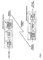
- FIG.4 A more detailed configuration of the speech encoding apparatus is shown in FIG.4, and a figure of waveforms to explain the signal processing in the encoding apparatus is shown in FIG.5.
- Signals A to G shown in FIG.4 correspond to signals A to G shown in FIG.5.
- frame configuring section 10 When speech signal A is inputted to frame configuring section 10, an analysis frame period for long analysis (long analysis frame) and an analysis frame period for short analysis (short analysis frame) are determined in frame configuring section 10. Then, frame configuring section 10 outputs long analysis frame signal B to windowing section 211 of long analysis section 21 and outputs short analysis frame signal C to windowing section 221 of short analysis section 22.
- a long analysis frame length (long analysis window length) and a short analysis frame length (short analysis window length) are predetermined, and, here, a description is made with the long analysis frame length being M1 and the short analysis frame length being M2 (M1>M2). Thus, a delay to occur is M2/2.
- windowing section 211 multiplies long analysis frame signal B with analysis length (analysis window length) M1 by an analysis window and outputs signal D multiplied by the analysis window to MDCT section 212.
- analysis window the long analysis window shown in FIG. 6 is used.
- the long analysis window is designed based on equation 3 with the analysis length being M1 and the overlapping period being M2/2.
- MDCT section 212 performs MDCT on signal D according to equation 4. MDCT section 212 then outputs transform coefficients F obtained by the MDCT to transform coefficient encoding section 30.
- ⁇ s1(i);0 ⁇ i ⁇ M1 ⁇ represents a time signal included in the long analysis frame
- ⁇ X1(k);0 ⁇ k ⁇ M1/2 ⁇ represents the transform coefficients F obtained by long analysis.
- windowing section 221 multiplies short analysis frame signal C with analysis length (analysis window length) M2 by an analysis window and outputs signal E multiplied by the analysis window to MDCT section 222.
- analysis window the short analysis window shown in FIG. 6 is used.
- the short analysis window is designed based on equation 2 with the analysis length being M2 (M2 ⁇ M1).
- MDCT section 222 performs MDCT on signal E according to equation 5. MDCT section 222 then outputs transform coefficients G obtained by the MDCT to transform coefficient encoding section 30.
- ⁇ s2(i);0 ⁇ i ⁇ M2 ⁇ represents a time signal included in a short analysis frame
- ⁇ X2(k);0 ⁇ k ⁇ M2/2 ⁇ represents transform coefficients G obtained by short analysis.
- Transform coefficient encoding section 30 encodes transform coefficients F: ⁇ X1(k) ⁇ and transform coefficients G: ⁇ X2(k) ⁇ and time-division multiplexes and outputs the respective encoded parameters . At this time, transform coefficient encoding section 30 performs more accurate (smaller quantization error) encoding on the transform coefficients ⁇ X2(k) ⁇ than that performed on the transform coefficients ⁇ X1(k) ⁇ .
- transform coefficient encoding section 30 performs encoding on the transform coefficients ⁇ X1(k) ⁇ and the transform coefficients ⁇ X2(k) ⁇ so that the number of bits to be encoded per transform coefficient for the transform coefficients ⁇ X2(k) ⁇ is set to a higher value than the number of bits to be encoded per transform coefficient for the transform coefficients ⁇ X1(k) ⁇ . That is, transform coefficient encoding section 30 performs encoding so that the quantization distortion of the transform coefficients ⁇ X2(k) ⁇ is smaller than that of the transform coefficients ⁇ X1(k) ⁇ .
- the encoding method described in Japanese Patent Application Laid-Open No.2003-323199 for example, can be used.
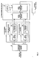
- FIG.7 A more detailed configuration of the speech decoding apparatus is shown in FIG.7, and a signal state transition is shown in FIG.8.
- Signals A to I shown in FIG.7 correspond to signals A to I shown in FIG.8.
- transform coefficient decoding section 50 When encoded parameters are inputted to transform coefficient decoding section 50, decoded transform coefficients(long analysis) ⁇ X1q(k);0 ⁇ k ⁇ M1/2 ⁇ :A and decoded transform coefficients(short analysis) ⁇ X2q(k);0 ⁇ k ⁇ M2/2 ⁇ :B, are decoded in transform coefficient decoding section 50.
- the transform coefficient decoding section 50 then outputs the decoded transform coefficients ⁇ X1q(k) ⁇ :A to IMDCT section 611 of long synthesizing section 61 and outputs the decoded transform coefficients ⁇ X2q(k) ⁇ :B to IMDCT section 621 of short synthesizing section 62.
- IMDCT section 611 performs IMDCT (inverse transform of MDCT performed by MDCT section 212) on the decoded transform coefficients ⁇ X1q(k) ⁇ and generates long synthesis signal C, and outputs long synthesis signal C to windowing section 612.
- Windowing section 612 multiplies long synthesis signal C by a synthesis window and outputs signal E multiplied by the synthesis window to intra-frame connecting section 71.
- the long analysis window shown in FIG.6 is used as in windowing section 211 of the speech encoding apparatus.
- IMDCT section 621 performs IMDCT (inverse transform of MDCT performed by MDCT section 222) on the decoded transform coefficients ⁇ X2q(k) ⁇ and generates short synthesis signal D, and outputs short synthesis signal D to windowing section 622.
- Windowing section 622 multiplies short synthesis signal D by a synthesis window and outputs signal F multiplied by the synthesis window to intra-frame connecting section 71.
- the short analysis window shown in FIG.6 is used as in windowing section 221 of the speech encoding apparatus.
- intra-frame connecting section 71 decoded signal G of the n-th frame is generated. Then, in inter-frame connecting section 73, periods corresponding to decoded signal G of the n-th frame and decoded signal H of the (n-1)-th frame are overlapped and added to generate adecodedspeechsignal. Thus, in intra-frame connecting section 71, periods corresponding to signal E and signal F are overlapped and added to generate the decoded signal of the n-th frame ⁇ sq(i);0 ⁇ i ⁇ M1 ⁇ :G.
- inter-frame connecting section 73 periods corresponding to decoded signal G of the n-th frame and decoded signal H of the (n-1) -th frame buffered in buffer 72 are overlapped and added to generate decoded speech signal I. Thereafter, decoded signal G of the n-th frame is stored in buffer 72 for processing for a subsequent frame ((n+1)-th frame).
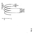
- FIG.9 the correspondence relationship between the arrangement of frames containing a speech signal and the arrangement of the analysis frames in analysis section 20 is shown in FIG.9.
- analysis of one frame period (a unit for generating encoded parameters) of a speech signal is performed always using a combination of long analysis and short analysis.
- MDCT analysis is performed using a combination of a long analysis length (long analysis) and a short analysis length (short analysis), and encoding processing is performed to reduce the quantization error of transform coefficients obtained by short analysis, so that it is possible to efficiently eliminate redundancy by setting a long analysis length where the delay is short and reduce the quantization distortion of the transform coefficients by setting a short analysis. Accordingly, it is possible to suppress the length of delay low to M2/2 and alleviate the distortion between frames.
- the short analysis window is arranged temporally after the long analysis window
- the long analysis window may be arranged temporally after the short analysis window as shown in FIG.10, for example.
- the amount of delay can be suppressed low, and the distortion between frames can be alleviated.
- the short analysis window is designed based on equation 2
- a window expressed by equation 3 may be used as the short analysis window, provided that the relationship between analysis length M2 of the short analysis window and analysis length M1 of the long analysis window is M2 ⁇ M1. That is, a window designed based on equation 3 with the analysis length being M2 may be used as the short analysis window. An example of this window is shown in FIG.11. Even with such an analysis window configuration, the length of delay can be suppressed low, and the distortion between frames can be alleviated.
- a speech signal to be inputted to a speech encoding apparatus is a beginning portion of a word or a transition portion where characteristics rapidly change, time resolution is required rather than frequency resolution. For such a speech signal, speech quality is improved by analyzing all analysis frames using short analysis frames.
- MDCT analysis is performed on each frame by switching between (1) a mode (long-short combined analysis mode) in which the analysis is performed by a combination of long analysis and short analysis and (2) a mode (all-short analysis mode) in which short analysis is repeatedly performed a plurality of times, according to the characteristics of the input speech signal.
- a mode long-short combined analysis mode
- all-short analysis mode short analysis is repeatedly performed a plurality of times
- FIG.13 The configuration of a speech encoding apparatus according to Embodiment 2 of the present invention is shown in FIG.13.
- the speech encoding apparatus according to the present embodiment having the configuration (FIG.4) in Embodiment 1 further includes determination section 15, multiplexing section 35, SW (switch) 11 and SW12.
- FIG.13 components that are the same as those in FIG.4 will be assigned the same reference numerals without further explanations.
- output to analysis section 20 from frame configuring section 10 and output to transform coefficient encoding section 30 from analysis section 20 are actually performed in a parallel manner as shown in FIG.4, here, for convenience of graphical representation, each output is shown by a single signal line.
- Determination section 15 analyzes the input speech signal and determines the characteristics of the signal. In characteristic determination, temporal variation of characteristics of the speech signal is monitored. When the amount of variation is less than a predetermined amount, it is determined to be a stationary portion, and, when the amount of change is greater than or equal to the predetermined amount, it is determined to be a non-stationary portion.
- the characteristics of the speech signal includes, for example, a short-term power or a short-term spectrum.
- Determination section 15 then switches the analysis mode of MDCT analysis between the long-short combined analysis mode and the all-short analysis mode, according to a determination result.
- determination section 15 connects SW11 and SW12 to the side of analysis section 20 and performs MDCT analysis in the long-short combined analysis mode using analysis section 20.
- determination section 15 connects SW11 and SW12 to the side of all-short analysis section 25 and performs MDCT analysis in the all-short analysis mode using all-short analysis section 25.
- the frame is analyzed using a combination of long analysis and short analysis, as in Embodiment 1, and, when the speech signal is a non-stationary portion, short analysis is repeatedly performed a plurality of times.
- all-short analysis section 25 When the all-short analysis mode is selected by determination section 15, all-short analysis section 25 performs analysis by MDCT expressed by equation 5 using an analysis window expressed by equation 2 where the analysis window length is M2.
- determination section 15 encodes determination information indicating whether the input speech signal is a stationary portion or a non-stationary portion, and outputs the encoded determination information to multiplexing section 35.
- the determination information is multiplexed with an encoded parameter to be outputted from transform coefficient encoding section 30 by multiplexing section 35 and outputted.
- FIG.14 The configuration of a speech decoding apparatus according to Embodiment 2 of the present invention is shown in FIG.14.
- the speech decoding apparatus according to the present embodiment having the configuration (FIG.7) in Embodiment 1 further includes demultiplexing section 45, determination information decoding section 55, all-short synthesizing section 65, SW21 and SW22.
- FIG.14 components that are the same as those in FIG.7 will be assigned the same reference numerals without further explanations.
- output to synthesizing section 60 from transform coefficient decoding section 50 and output to intra-frame connecting section 71 from synthesizing section 60 are actually performed in a parallel manner as shown in FIG.7, here, for convenience of graphical representation, each output is shown by a single signal line.
- Demultiplexing section 45 separates encoded parameters to be inputted into an encoded parameter indicating determination information and an encoded parameter indicating transform coefficients, and outputs the encoded parameters to determination information decoding section 55 and transform coefficient decoding section 50, respectively.
- Determination information decoding section 55 decodes the inputted determination information.
- determination information decoding section 55 connects SW21 and SW22 to the side of synthesizing section 60 and generates a synthesis signal using synthesizing section 60. Generation of a synthesis signal using synthesizing section 60 is the same as that described in Embodiment 1.
- determination information decoding section 55 connects SW21 and SW22 to the side of all-short synthesizing section 65 and generates a synthesis signal using all-short synthesizing section 65. All-short synthesizing section 65 performs IMDCT processing on each of a plurality of decoded transform coefficients (short analysis) in one frame and generates a synthesis signal.
- the speech signal of that frame is analyzed by a combination of long analysis and short analysis, and, when an input speech signal is a non-stationary portion (when the input speech signal rapidly changes), the speech signal of that frame is analyzed by short analysis to improve the time resolution, so that it is possible to perform optimal MDCT analysis according to the characteristics of the input speech signal, and, even when the characteristics of the input speech signal change, maintain good speech quality.
- the overlapping period in the long-short combined analysis mode is the same as the overlapping period in the all-short analysis mode.
- an analysis frame for transition such as LONG_START_WINDOW or LONG_STOP_WINDOW, described in ISO/IEC IS 13818-7
- AAC Advanced Audio Coding
- the analysis mode of the subsequent frame can be determined according to the SNR of the connecting portion, so that the misdetermination of the analysis mode can be reduced.
- the speech encoding apparatus and the speech decoding apparatus according to the embodiments can also be provided to a radio communication apparatus such as a radio communication mobile station apparatus and a radio communication base station apparatus used in a mobile communication system.
- a radio communication apparatus such as a radio communication mobile station apparatus and a radio communication base station apparatus used in a mobile communication system.
- each function block used to explain the above-described embodiments is typically implemented as an LSI constituted by an integrated circuit. These may be individual chips or may partially or totally contained on a single chip.
- each function block is described as an LSI, but this may also be referred to as "IC”, “system LSI”, “super LSI”, “ultra LSI” depending on differing extents of integration.
- circuit integration is not limited to LSI's, and implementation using dedicated circuitry or general purpose processors is also possible.
- LSI manufacture utilization of a programmable FPGA (Field Programmable Gate Array) or a reconfigurable processor in which connections and settings of circuit cells within an LSI can be reconfigured is also possible.
- FPGA Field Programmable Gate Array
- the present invention can be applied to a communication apparatus such as in a mobile communication system and a packet communication system using the Internet Protocol.
Landscapes
- Engineering & Computer Science (AREA)
- Physics & Mathematics (AREA)
- Health & Medical Sciences (AREA)
- Signal Processing (AREA)
- Audiology, Speech & Language Pathology (AREA)
- Human Computer Interaction (AREA)
- Computational Linguistics (AREA)
- Acoustics & Sound (AREA)
- Multimedia (AREA)
- Spectroscopy & Molecular Physics (AREA)
- Theoretical Computer Science (AREA)
- Compression, Expansion, Code Conversion, And Decoders (AREA)
- Reduction Or Emphasis Of Bandwidth Of Signals (AREA)
- Electrophonic Musical Instruments (AREA)
Abstract
Description
- The present invention relates to a speech encoding apparatus and a speech encoding method.
- In speech encoding, transform encoding whereby a time signal is transformed into a frequency domain and transform coefficients are encoded, can efficiently eliminate redundancy contained in the time domain signal. In addition, in the transform encoding, by utilizing perceptual characteristics represented in the frequency domain, it is possible to implement encoding in which quantization distortion is difficult to be perceived even at a low bit rate.
- In transform encoding for the recent years, a transform technique called lapped orthogonal transform (LOT) is often used. In LOT, transform is performed based on an orthogonal function taking into consideration not only the orthogonal components within a block but also the orthogonal components between adjacent blocks. Typical techniques of such transform include MDCT (Modified Discrete Cosine Transform). In MDCT, analysis frames are arranged so that a current analysis frame overlaps previous and subsequent analysis frames, and analysis is performed. At this time, it is only necessary to encode coefficients corresponding to half of the analysis length out of transformed coefficients, so that efficient encoding can be performed by using MDCT. In addition, upon synthesis, the current frame and its adjacent frames are overlapped and added, thereby providing a feature that even under circumstances where different quantization distortions occur for each frame, discontinuity at frame boundaries is unlikely to occur.
- Normally, when analysis/synthesis is performed by MDCT, a target signal is multiplied by an analysis window and a synthesis window which are window functions. The analysis window/synthesis window to be used at this time has a slope at a portion to be overlapped with the adjacent frames. The length of the overlapping period (that is, the length of the slope) and a delay necessary for buffering an input frame correspond to the length of a delay occurring by the MDCT analysis/synthesis. If this delay increases in bidirectional communication, it takes time for a response from a terminal to arrive at the other terminal, and therefore smooth conversation cannot be performed. Thus, it is preferable that the delay is as short as possible.
- Conventional MDCT will be described below.
- When a condition expressed by
equation 1 is satisfied, the analysis window/synthesis window to be used in MDCT realizes perfect reconstruction (where distortion due to transform is zero on the assumption that there is no quantization distortion).
[1]
- As a typical window satisfying the condition of
equation 1, Non-PatentDocument 1 proposes a sine window expressed byequation 2. The sine window is as shown in FIG.1. When such a sine window is used, side lobes are sufficiently attenuated in the spectrum characteristics of the sine window, so that accurate spectrum analysis is possible.
[2]
- Non-Patent
Document 2 proposes a method of performing MDCT analysis/synthesis using the window expressed by equation 3 as a window satisfying the condition ofequation 1. Here, N is the length of the analysis window, and L is the length of the overlapping period. The window expressed by equation 3 is as shown in FIG.2. When such a window is used, the overlapping period is L, and thus the delay by this window is represented by L. Therefore, the occurrence of the delay can be suppressed by setting overlapping period L short.
[3]
Non-Patent Document 1 : Takehiro Moriya, "Speech Coding", the Institute of Electronics, Information and Communication Engineers, October 20, 1998, pp. 36-38
Non-Patent Document 2: M. Iwadare, et al., "A 128 kb/s Hi-Fi Audio CODEC Based on Adaptive Transform Coding with Adaptive Block Size MDCT," IEEE Journal on Selected Areas in Communications, Vol. 10, No. 1, pp. 138-144, Jan. 1992. - When the sine window expressed by
equation 2 is used, as shown in FIG. 1, an overlapping period of adjacent analysis frames has a half length of the analysis frame. In this example, the analysis frame length is N, and thus the overlapping period is N/2. Therefore, on the synthesis side, in order to synthesize the signal located at N/2 to N-1, unless information of the subsequent analysis frame is obtained, the signal cannot be synthesized. That is, until the sample value located at (3N/2)-1 is obtained, MDCT analysis cannot be performed on the subsequent analysis frame. Only after the sample at the location of (3N/2)-1 is obtained, MDCT analysis is performed on the subsequent analysis frame, and the signal at N/2 to N-1 can be synthesized using transform coefficients of the analysis frame. Accordingly, when a sine window is used, a delay with a length of N/2 occurs. - On the other hand, when the window expressed by equation 3 is used, discontinuity between frames is likely to occur since overlapping period L is short. When MDCT analysis is performed on each of the current analysis frame and the subsequent analysis frame, and the transform coefficients are quantized, quantization is independently performed, and therefore different quantization distortions occur in the current analysis frame and the subsequent analysis frame. When transform coefficients to which quantization distortion is added are inverse transformed into the time domain, the quantization distortion is added over the entire synthesis frame in the time signal. That is, quantization distortion of the current synthesis frame and quantization distortion of the subsequent synthesis frame occur without correlation. Therefore, when the overlapping period is short, discontinuity of a decoded signal resulting from quantization distortion cannot be sufficiently absorbed in an adjacent portion between synthesis frames, and accordingly, the distortion between the frames is perceived. This tendency markedly appears when overlapping period L is made shorter.
- It is therefore an object of the present invention to provide a speech encoding apparatus and a speech encoding method that are capable of suppressing the amount of delay low and alleviating the distortion between frames.
- A speech encoding apparatus of the present invention adopts a configuration including: a analysis section that performs MDCT analysis on one frame of a time-domain speech signal by both a long analysis length and a short analysis length to obtain two types of transform coefficients in a frequency domain; and an encoding section that encodes the two types of transform coefficients.
- According to the present invention, it is possible to suppress the amount of delay low and alleviate the distortion between frames.
-
- FIG.1 shows a conventional analysis window;
- FIG.2 shows a conventional analysis window;
- FIG.3 is a block diagram showing the configurations of a speech encoding apparatus and a speech decoding apparatus according to
Embodiment 1 of the present invention; - FIG.4 is a block diagram showing the configuration of the speech encoding apparatus according to
Embodiment 1 of the present invention; - FIG.5 is a figure of waveforms to explain the signal processing in the encoding apparatus diagram of the speech encoding apparatus according to
Embodiment 1 of the present invention; - FIG.6 shows an analysis window according to
Embodiment 1 of the present invention; - FIG.7 is a block diagram showing the configuration of the speech decoding apparatus according to
Embodiment 1 of the present invention; - FIG.8 is a signal state transition diagram of the speech decoding apparatus according to
Embodiment 1 of the present invention; - FIG.9 illustrates operation of the speech encoding apparatus according to
Embodiment 1 of the present invention; - FIG.10 shows an analysis window according to
Embodiment 1 of the present invention; - FIG.11 shows an analysis window according to
Embodiment 1 of the present invention; - FIG.12 shows an analysis window according to
Embodiment 2 of the present invention; - FIG.13 is a block diagram showing the configuration of a speech encoding apparatus according to
Embodiment 2 of the present invention; and - FIG.14 is a block diagram showing the configuration of a speech decoding apparatus according to
Embodiment 2 of the present invention. - Embodiments of the present invention will be described in detail below with reference to the accompanying drawings.
- The configurations of a speech encoding apparatus and a speech decoding apparatus according to
Embodiment 1 of the present invention are shown in FIG.3. As shown in the drawing, the speech encoding apparatus includesframe configuring section 10,analysis section 20 and transformcoefficient encoding section 30. The speech decoding apparatus includes transformcoefficient decoding section 50, synthesizingsection 60 andframe connecting section 70. - In the speech encoding apparatus,
frame configuring section 10 forms a time-domain speech signal to be inputted, into frames.Analysis section 20 transforms the time-domain speech signal broken into frames, into a frequency-domain signal by MDCT analysis. Transformcoefficient encoding section 30 encodes transform coefficients obtained byanalysis section 20 and outputs encoded parameters. The encoded parameters are transmitted to the speech decoding apparatus through a transmission channel. - In the speech decoding apparatus, transform
coefficient decoding section 50 decodes the encoded parameters transmitted through the transmission channel. Synthesizingsection 60 generates a time-domain signal from decoded transform coefficients by MDCT synthesis.Frame connecting section 70 connects the time-domain signal so that there is no discontinuity between adjacent frames, and outputs a decoded speech signal. - Next, the speech encoding apparatus will be described in more detail. A more detailed configuration of the speech encoding apparatus is shown in FIG.4, and a figure of waveforms to explain the signal processing in the encoding apparatus is shown in FIG.5. Signals A to G shown in FIG.4 correspond to signals A to G shown in FIG.5.
- When speech signal A is inputted to frame configuring
section 10, an analysis frame period for long analysis (long analysis frame) and an analysis frame period for short analysis (short analysis frame) are determined inframe configuring section 10. Then,frame configuring section 10 outputs long analysis frame signal B towindowing section 211 oflong analysis section 21 and outputs short analysis frame signal C towindowing section 221 ofshort analysis section 22. A long analysis frame length (long analysis window length) and a short analysis frame length (short analysis window length) are predetermined, and, here, a description is made with the long analysis frame length being M1 and the short analysis frame length being M2 (M1>M2). Thus, a delay to occur is M2/2. - In
long analysis section 21,windowing section 211 multiplies long analysis frame signal B with analysis length (analysis window length) M1 by an analysis window and outputs signal D multiplied by the analysis window toMDCT section 212. As the analysis window, the long analysis window shown in FIG. 6 is used. The long analysis window is designed based on equation 3 with the analysis length being M1 and the overlapping period being M2/2. -
MDCT section 212 performs MDCT on signal D according to equation 4.MDCT section 212 then outputs transform coefficients F obtained by the MDCT to transformcoefficient encoding section 30. In equation 4, {s1(i);0≤i<M1} represents a time signal included in the long analysis frame, and {X1(k);0≤k<M1/2} represents the transform coefficients F obtained by long analysis.
[4]
- On the other hand, in
short analysis section 22,windowing section 221 multiplies short analysis frame signal C with analysis length (analysis window length) M2 by an analysis window and outputs signal E multiplied by the analysis window toMDCT section 222. As the analysis window, the short analysis window shown in FIG. 6 is used. The short analysis window is designed based onequation 2 with the analysis length being M2 (M2<M1). -
MDCT section 222 performs MDCT on signal E according to equation 5.MDCT section 222 then outputs transform coefficients G obtained by the MDCT to transformcoefficient encoding section 30. In equation 5, {s2(i);0≤i<M2} represents a time signal included in a short analysis frame, and {X2(k);0≤k<M2/2} represents transform coefficients G obtained by short analysis.
[5]
- Transform
coefficient encoding section 30 encodes transform coefficients F:{X1(k)} and transform coefficients G: {X2(k)} and time-division multiplexes and outputs the respective encoded parameters . At this time, transformcoefficient encoding section 30 performs more accurate (smaller quantization error) encoding on the transform coefficients {X2(k)} than that performed on the transform coefficients {X1(k)}. For example, transformcoefficient encoding section 30 performs encoding on the transform coefficients {X1(k)} and the transform coefficients {X2(k)} so that the number of bits to be encoded per transform coefficient for the transform coefficients {X2(k)} is set to a higher value than the number of bits to be encoded per transform coefficient for the transform coefficients {X1(k)}. That is, transformcoefficient encoding section 30 performs encoding so that the quantization distortion of the transform coefficients {X2(k)} is smaller than that of the transform coefficients {X1(k)}. For an encoding method in transformcoefficient encoding section 30, the encoding method described inJapanese Patent Application Laid-Open No.2003-323199 - Next, the speech decoding apparatus will be described in more detail. A more detailed configuration of the speech decoding apparatus is shown in FIG.7, and a signal state transition is shown in FIG.8. Signals A to I shown in FIG.7 correspond to signals A to I shown in FIG.8.
- When encoded parameters are inputted to transform
coefficient decoding section 50, decoded transform coefficients(long analysis) {X1q(k);0≤k<M1/2}:A and decoded transform coefficients(short analysis) {X2q(k);0≤k<M2/2}:B, are decoded in transformcoefficient decoding section 50. The transformcoefficient decoding section 50 then outputs the decoded transform coefficients {X1q(k)}:A toIMDCT section 611 of long synthesizingsection 61 and outputs the decoded transform coefficients {X2q(k)}:B toIMDCT section 621 ofshort synthesizing section 62. - In long synthesizing
section 61,IMDCT section 611 performs IMDCT (inverse transform of MDCT performed by MDCT section 212) on the decoded transform coefficients {X1q(k)} and generates long synthesis signal C, and outputs long synthesis signal C towindowing section 612. -
Windowing section 612 multiplies long synthesis signal C by a synthesis window and outputs signal E multiplied by the synthesis window to intra-frame connectingsection 71. As the synthesis window, the long analysis window shown in FIG.6 is used as inwindowing section 211 of the speech encoding apparatus. - On the other hand, in
short synthesizing section 62,IMDCT section 621 performs IMDCT (inverse transform of MDCT performed by MDCT section 222) on the decoded transform coefficients {X2q(k)} and generates short synthesis signal D, and outputs short synthesis signal D towindowing section 622. -
Windowing section 622 multiplies short synthesis signal D by a synthesis window and outputs signal F multiplied by the synthesis window to intra-frame connectingsection 71. As the synthesis window, the short analysis window shown in FIG.6 is used as inwindowing section 221 of the speech encoding apparatus. - In
intra-frame connecting section 71, decoded signal G of the n-th frame is generated. Then, ininter-frame connecting section 73, periods corresponding to decoded signal G of the n-th frame and decoded signal H of the (n-1)-th frame are overlapped and added to generate adecodedspeechsignal. Thus, inintra-frame connecting section 71, periods corresponding to signal E and signal F are overlapped and added to generate the decoded signal of the n-th frame {sq(i);0≤i<M1}:G. Then, ininter-frame connecting section 73, periods corresponding to decoded signal G of the n-th frame and decoded signal H of the (n-1) -th frame buffered inbuffer 72 are overlapped and added to generate decoded speech signal I. Thereafter, decoded signal G of the n-th frame is stored inbuffer 72 for processing for a subsequent frame ((n+1)-th frame). - Next, the correspondence relationship between the arrangement of frames containing a speech signal and the arrangement of the analysis frames in
analysis section 20 is shown in FIG.9. As shown in FIG.9, in the present embodiment, analysis of one frame period (a unit for generating encoded parameters) of a speech signal is performed always using a combination of long analysis and short analysis. - As described above, in the present embodiment, MDCT analysis is performed using a combination of a long analysis length (long analysis) and a short analysis length (short analysis), and encoding processing is performed to reduce the quantization error of transform coefficients obtained by short analysis, so that it is possible to efficiently eliminate redundancy by setting a long analysis length where the delay is short and reduce the quantization distortion of the transform coefficients by setting a short analysis. Accordingly, it is possible to suppress the length of delay low to M2/2 and alleviate the distortion between frames.
- For the arrangement of a long analysis window and a short analysis window in one frame period, although, in FIG. 6, the short analysis window is arranged temporally after the long analysis window, the long analysis window may be arranged temporally after the short analysis window as shown in FIG.10, for example. Even with the arrangement shown in FIG. 10, as with the arrangement shown in FIG.6, the amount of delay can be suppressed low, and the distortion between frames can be alleviated.
- Although, in the present embodiment, the short analysis window is designed based on
equation 2, a window expressed by equation 3 may be used as the short analysis window, provided that the relationship between analysis length M2 of the short analysis window and analysis length M1 of the long analysis window is M2<M1. That is, a window designed based on equation 3 with the analysis length being M2 may be used as the short analysis window. An example of this window is shown in FIG.11. Even with such an analysis window configuration, the length of delay can be suppressed low, and the distortion between frames can be alleviated. - When a speech signal to be inputted to a speech encoding apparatus is a beginning portion of a word or a transition portion where characteristics rapidly change, time resolution is required rather than frequency resolution. For such a speech signal, speech quality is improved by analyzing all analysis frames using short analysis frames.
- In view of this, in the present embodiment, MDCT analysis is performed on each frame by switching between (1) a mode (long-short combined analysis mode) in which the analysis is performed by a combination of long analysis and short analysis and (2) a mode (all-short analysis mode) in which short analysis is repeatedly performed a plurality of times, according to the characteristics of the input speech signal. An example of analysis/synthesis windows to be used for each frame in the all-short analysis mode is shown in FIG.12. The long-short combined analysis mode is the same as that described in
Embodiment 1. - The configuration of a speech encoding apparatus according to
Embodiment 2 of the present invention is shown in FIG.13. As shown in the drawing, the speech encoding apparatus according to the present embodiment having the configuration (FIG.4) inEmbodiment 1 further includesdetermination section 15, multiplexingsection 35, SW (switch) 11 and SW12. In FIG.13, components that are the same as those in FIG.4 will be assigned the same reference numerals without further explanations. Although output toanalysis section 20 fromframe configuring section 10 and output to transformcoefficient encoding section 30 fromanalysis section 20 are actually performed in a parallel manner as shown in FIG.4, here, for convenience of graphical representation, each output is shown by a single signal line. -
Determination section 15 analyzes the input speech signal and determines the characteristics of the signal. In characteristic determination, temporal variation of characteristics of the speech signal is monitored. When the amount of variation is less than a predetermined amount, it is determined to be a stationary portion, and, when the amount of change is greater than or equal to the predetermined amount, it is determined to be a non-stationary portion. The characteristics of the speech signal includes, for example, a short-term power or a short-term spectrum. -
Determination section 15 then switches the analysis mode of MDCT analysis between the long-short combined analysis mode and the all-short analysis mode, according to a determination result. Thus, when the input speech signal is a stationary portion,determination section 15 connects SW11 and SW12 to the side ofanalysis section 20 and performs MDCT analysis in the long-short combined analysis mode usinganalysis section 20. On the other hand, when the input speech signal is a non-stationary portion,determination section 15 connects SW11 and SW12 to the side of all-short analysis section 25 and performs MDCT analysis in the all-short analysis mode using all-short analysis section 25. By this switching, when the speech signal is a stationary portion, the frame is analyzed using a combination of long analysis and short analysis, as inEmbodiment 1, and, when the speech signal is a non-stationary portion, short analysis is repeatedly performed a plurality of times. - When the all-short analysis mode is selected by
determination section 15, all-short analysis section 25 performs analysis by MDCT expressed by equation 5 using an analysis window expressed byequation 2 where the analysis window length is M2. - In addition,
determination section 15 encodes determination information indicating whether the input speech signal is a stationary portion or a non-stationary portion, and outputs the encoded determination information to multiplexingsection 35. The determination information is multiplexed with an encoded parameter to be outputted from transformcoefficient encoding section 30 by multiplexingsection 35 and outputted. - The configuration of a speech decoding apparatus according to
Embodiment 2 of the present invention is shown in FIG.14. As shown in the drawing, the speech decoding apparatus according to the present embodiment having the configuration (FIG.7) inEmbodiment 1 further includesdemultiplexing section 45, determinationinformation decoding section 55, all-short synthesizing section 65, SW21 and SW22. In FIG.14, components that are the same as those in FIG.7 will be assigned the same reference numerals without further explanations. Although output to synthesizingsection 60 from transformcoefficient decoding section 50 and output to intra-frame connectingsection 71 from synthesizingsection 60 are actually performed in a parallel manner as shown in FIG.7, here, for convenience of graphical representation, each output is shown by a single signal line. -
Demultiplexing section 45 separates encoded parameters to be inputted into an encoded parameter indicating determination information and an encoded parameter indicating transform coefficients, and outputs the encoded parameters to determinationinformation decoding section 55 and transformcoefficient decoding section 50, respectively. - Determination
information decoding section 55 decodes the inputted determination information. When the determination information indicates a stationary portion, determinationinformation decoding section 55 connects SW21 and SW22 to the side of synthesizingsection 60 and generates a synthesis signal using synthesizingsection 60. Generation of a synthesis signal using synthesizingsection 60 is the same as that described inEmbodiment 1. On the other hand, when the determination information indicates a non-stationary portion, determinationinformation decoding section 55 connects SW21 and SW22 to the side of all-short synthesizing section 65 and generates a synthesis signal using all-short synthesizing section 65. All-short synthesizing section 65 performs IMDCT processing on each of a plurality of decoded transform coefficients (short analysis) in one frame and generates a synthesis signal. - As described above, in the present embodiment, when, in one frame, an input speech signal is a stationary portion and stable, the speech signal of that frame is analyzed by a combination of long analysis and short analysis, and, when an input speech signal is a non-stationary portion (when the input speech signal rapidly changes), the speech signal of that frame is analyzed by short analysis to improve the time resolution, so that it is possible to perform optimal MDCT analysis according to the characteristics of the input speech signal, and, even when the characteristics of the input speech signal change, maintain good speech quality.
- In the present embodiment, the overlapping period in the long-short combined analysis mode is the same as the overlapping period in the all-short analysis mode. Thus, there is no need to use an analysis frame for transition, such as LONG_START_WINDOW or LONG_STOP_WINDOW, described in ISO/IEC IS 13818-7 Information technology - Generic coding of moving pictures and associated audio information - Part 7: Advanced Audio Coding (AAC), for example.
- For another method of determining between the long-short combined analysis mode and the all-short analysis mode, there is a method in which such determination is made according to the SNR of the signal located at a portion connected to a subsequent frame with respect to the original signal. By using this determination method, the analysis mode of the subsequent frame can be determined according to the SNR of the connecting portion, so that the misdetermination of the analysis mode can be reduced.
- The above-described embodiments can be applied to an extension layer of layered encoding where the number of layers is two or more.
- The speech encoding apparatus and the speech decoding apparatus according to the embodiments can also be provided to a radio communication apparatus such as a radio communication mobile station apparatus and a radio communication base station apparatus used in a mobile communication system.
- In the above embodiments, the case has been described as an example where the present invention is implemented with hardware, the present invention can be implemented with software.
- Furthermore, each function block used to explain the above-described embodiments is typically implemented as an LSI constituted by an integrated circuit. These may be individual chips or may partially or totally contained on a single chip.
- Here, each function block is described as an LSI, but this may also be referred to as "IC", "system LSI", "super LSI", "ultra LSI" depending on differing extents of integration.
- Further, the method of circuit integration is not limited to LSI's, and implementation using dedicated circuitry or general purpose processors is also possible. After LSI manufacture, utilization of a programmable FPGA (Field Programmable Gate Array) or a reconfigurable processor in which connections and settings of circuit cells within an LSI can be reconfigured is also possible.
- Further, if integrated circuit technology comes out to replace LSI's as a result of the development of semiconductor technology or a derivative other technology, it is naturally also possible to carry out function block integration using this technology. Application in biotechnology is also possible.
- The present application is based on
Japanese Patent Application No. 2004-311143, filed on October 26, 2004 - The present invention can be applied to a communication apparatus such as in a mobile communication system and a packet communication system using the Internet Protocol.
Claims (6)
- A speech encoding apparatus comprising:a analysis section that performs MDCT analysis on one frame of a time-domain speech signal by both a long analysis length and a short analysis length to obtain two types of transform coefficients in a frequency domain; andan encoding section that encodes the two types of transform coefficients.
- The speech encoding apparatus according to claim 1, wherein the encoding section performs more accurate encoding on the second transform coefficients obtained by the short analysis length than encoding performed on the first transform coefficients obtained by the long analysis length.
- The speech encoding apparatus according to claim 1, further comprising:a determination section that determines whether the speech signal is a stationary portion or a non-stationary portion; anda second analysis section that repeats MDCT analysis on the one frame a plurality of times by the short analysis length when the speech signal is the non-stationary portion.
- A radio communication mobile station apparatus comprising the speech encoding apparatus according to claim 1.
- A radio communication base station apparatus comprising the speech encoding apparatus according to claim 1.
- A speech encoding method comprising the steps of:performing MDCT analysis on one frame of a time-domain speech signal by both a long analysis length and a short analysis length to obtain two types of transform coefficients in a frequency domain; andencoding the two types of transform coefficients.
Applications Claiming Priority (2)
| Application Number | Priority Date | Filing Date | Title |
|---|---|---|---|
| JP2004311143 | 2004-10-26 | ||
| PCT/JP2005/019578 WO2006046546A1 (en) | 2004-10-26 | 2005-10-25 | Sound encoding device and sound encoding method |
Publications (3)
| Publication Number | Publication Date |
|---|---|
| EP1793372A1 true EP1793372A1 (en) | 2007-06-06 |
| EP1793372A4 EP1793372A4 (en) | 2008-01-23 |
| EP1793372B1 EP1793372B1 (en) | 2011-12-14 |
Family
ID=36227786
Family Applications (1)
| Application Number | Title | Priority Date | Filing Date |
|---|---|---|---|
| EP05799362A Active EP1793372B1 (en) | 2004-10-26 | 2005-10-25 | Speech encoding apparatus and speech encoding method |
Country Status (8)
| Country | Link |
|---|---|
| US (1) | US8326606B2 (en) |
| EP (1) | EP1793372B1 (en) |
| JP (1) | JP5100124B2 (en) |
| KR (1) | KR20070068424A (en) |
| CN (1) | CN101061533B (en) |
| AT (1) | ATE537536T1 (en) |
| BR (1) | BRPI0517513A (en) |
| WO (1) | WO2006046546A1 (en) |
Cited By (5)
| Publication number | Priority date | Publication date | Assignee | Title |
|---|---|---|---|---|
| WO2008016945A3 (en) * | 2006-07-31 | 2008-04-10 | Qualcomm Inc | Systems and methods for modifying a window with a frame associated with an audio signal |
| WO2009047675A2 (en) * | 2007-10-10 | 2009-04-16 | Koninklijke Philips Electronics N.V. | Encoding and decoding of an audio signal |
| WO2013092292A1 (en) * | 2011-12-21 | 2013-06-27 | Dolby International Ab | Audio encoder with parallel architecture |
| US9653088B2 (en) | 2007-06-13 | 2017-05-16 | Qualcomm Incorporated | Systems, methods, and apparatus for signal encoding using pitch-regularizing and non-pitch-regularizing coding |
| US20220005486A1 (en) * | 2008-09-18 | 2022-01-06 | Electronics And Telecommunications Research Institute | Encoding apparatus and decoding apparatus for transforming between modified discrete cosine transform-based coder and different coder |
Families Citing this family (21)
| Publication number | Priority date | Publication date | Assignee | Title |
|---|---|---|---|---|
| JP5100124B2 (en) * | 2004-10-26 | 2012-12-19 | パナソニック株式会社 | Speech coding apparatus and speech coding method |
| WO2007037361A1 (en) | 2005-09-30 | 2007-04-05 | Matsushita Electric Industrial Co., Ltd. | Audio encoding device and audio encoding method |
| JPWO2007043643A1 (en) * | 2005-10-14 | 2009-04-16 | パナソニック株式会社 | Speech coding apparatus, speech decoding apparatus, speech coding method, and speech decoding method |
| US20100161323A1 (en) * | 2006-04-27 | 2010-06-24 | Panasonic Corporation | Audio encoding device, audio decoding device, and their method |
| US8036903B2 (en) | 2006-10-18 | 2011-10-11 | Fraunhofer-Gesellschaft Zur Foerderung Der Angewandten Forschung E.V. | Analysis filterbank, synthesis filterbank, encoder, de-coder, mixer and conferencing system |
| WO2008071353A2 (en) | 2006-12-12 | 2008-06-19 | Fraunhofer-Gesellschaft Zur Förderung Der Angewandten Forschung E.V: | Encoder, decoder and methods for encoding and decoding data segments representing a time-domain data stream |
| CN101548318B (en) * | 2006-12-15 | 2012-07-18 | 松下电器产业株式会社 | Encoding device, decoding device, and method thereof |
| CN101790756B (en) * | 2007-08-27 | 2012-09-05 | 爱立信电话股份有限公司 | Transient detector and method for supporting encoding of an audio signal |
| CN101604983B (en) * | 2008-06-12 | 2013-04-24 | 华为技术有限公司 | Device, system and method for coding and decoding |
| MY152252A (en) * | 2008-07-11 | 2014-09-15 | Fraunhofer Ges Forschung | Apparatus and method for encoding/decoding an audio signal using an aliasing switch scheme |
| WO2011047887A1 (en) * | 2009-10-21 | 2011-04-28 | Dolby International Ab | Oversampling in a combined transposer filter bank |
| EP2460158A4 (en) * | 2009-07-27 | 2013-09-04 | A method and an apparatus for processing an audio signal | |
| CN102243872A (en) * | 2010-05-10 | 2011-11-16 | 炬力集成电路设计有限公司 | Method and system for encoding and decoding digital audio signals |
| WO2012070866A2 (en) * | 2010-11-24 | 2012-05-31 | 엘지전자 주식회사 | Speech signal encoding method and speech signal decoding method |
| FR2977439A1 (en) * | 2011-06-28 | 2013-01-04 | France Telecom | WINDOW WINDOWS IN ENCODING / DECODING BY TRANSFORMATION WITH RECOVERY, OPTIMIZED IN DELAY. |
| KR101390551B1 (en) * | 2012-09-24 | 2014-04-30 | 충북대학교 산학협력단 | Method of low delay modified discrete cosine transform |
| KR20140075466A (en) | 2012-12-11 | 2014-06-19 | 삼성전자주식회사 | Encoding and decoding method of audio signal, and encoding and decoding apparatus of audio signal |
| CA2900437C (en) | 2013-02-20 | 2020-07-21 | Christian Helmrich | Apparatus and method for encoding or decoding an audio signal using a transient-location dependent overlap |
| EP2830058A1 (en) * | 2013-07-22 | 2015-01-28 | Fraunhofer-Gesellschaft zur Förderung der angewandten Forschung e.V. | Frequency-domain audio coding supporting transform length switching |
| BR112017010911B1 (en) * | 2014-12-09 | 2023-11-21 | Dolby International Ab | DECODING METHOD AND SYSTEM FOR HIDING ERRORS IN DATA PACKETS THAT MUST BE DECODED IN AN AUDIO DECODER BASED ON MODIFIED DISCRETE COSINE TRANSFORMATION |
| KR20180081504A (en) * | 2015-11-09 | 2018-07-16 | 소니 주식회사 | Decode device, decode method, and program |
Citations (5)
| Publication number | Priority date | Publication date | Assignee | Title |
|---|---|---|---|---|
| EP0559383A1 (en) * | 1992-03-02 | 1993-09-08 | AT&T Corp. | A method and apparatus for coding audio signals based on perceptual model |
| US5414795A (en) * | 1991-03-29 | 1995-05-09 | Sony Corporation | High efficiency digital data encoding and decoding apparatus |
| EP0697665A2 (en) * | 1994-08-16 | 1996-02-21 | Sony Corporation | Method and apparatus for encoding, transmitting and decoding information |
| EP0725493A2 (en) * | 1995-01-31 | 1996-08-07 | AT&T Corp. | A method of window switching in an audio coder |
| US5825320A (en) * | 1996-03-19 | 1998-10-20 | Sony Corporation | Gain control method for audio encoding device |
Family Cites Families (21)
| Publication number | Priority date | Publication date | Assignee | Title |
|---|---|---|---|---|
| US5487086A (en) * | 1991-09-13 | 1996-01-23 | Comsat Corporation | Transform vector quantization for adaptive predictive coding |
| JP3531177B2 (en) | 1993-03-11 | 2004-05-24 | ソニー株式会社 | Compressed data recording apparatus and method, compressed data reproducing method |
| US5533052A (en) * | 1993-10-15 | 1996-07-02 | Comsat Corporation | Adaptive predictive coding with transform domain quantization based on block size adaptation, backward adaptive power gain control, split bit-allocation and zero input response compensation |
| AU709245B2 (en) * | 1994-08-22 | 1999-08-26 | Sony Corporation | Transmitter-receiver |
| US5852806A (en) * | 1996-03-19 | 1998-12-22 | Lucent Technologies Inc. | Switched filterbank for use in audio signal coding |
| US5848391A (en) * | 1996-07-11 | 1998-12-08 | Fraunhofer-Gesellschaft Zur Forderung Der Angewandten Forschung E.V. | Method subband of coding and decoding audio signals using variable length windows |
| US6138120A (en) * | 1998-06-19 | 2000-10-24 | Oracle Corporation | System for sharing server sessions across multiple clients |
| JP2000134106A (en) * | 1998-10-29 | 2000-05-12 | Matsushita Electric Ind Co Ltd | Method of discriminating and adapting block size in frequency region for audio conversion coding |
| DE19921122C1 (en) * | 1999-05-07 | 2001-01-25 | Fraunhofer Ges Forschung | Method and device for concealing an error in a coded audio signal and method and device for decoding a coded audio signal |
| US20020147652A1 (en) * | 2000-10-18 | 2002-10-10 | Ahmed Gheith | System and method for distruibuted client state management across a plurality of server computers |
| JP2002196792A (en) * | 2000-12-25 | 2002-07-12 | Matsushita Electric Ind Co Ltd | Audio coding system, audio coding method, audio coder using the method, recording medium, and music distribution system |
| WO2002056297A1 (en) * | 2001-01-11 | 2002-07-18 | Sasken Communication Technologies Limited | Adaptive-block-length audio coder |
| JP2003066998A (en) | 2001-08-28 | 2003-03-05 | Mitsubishi Electric Corp | Acoustic signal encoding apparatus |
| US7460993B2 (en) * | 2001-12-14 | 2008-12-02 | Microsoft Corporation | Adaptive window-size selection in transform coding |
| JP2003216188A (en) | 2002-01-25 | 2003-07-30 | Matsushita Electric Ind Co Ltd | Audio signal encoding method, encoder and storage medium |
| EP1394772A1 (en) * | 2002-08-28 | 2004-03-03 | Deutsche Thomson-Brandt Gmbh | Signaling of window switchings in a MPEG layer 3 audio data stream |
| JP2004252068A (en) | 2003-02-19 | 2004-09-09 | Matsushita Electric Ind Co Ltd | Device and method for encoding digital audio signal |
| US7325023B2 (en) * | 2003-09-29 | 2008-01-29 | Sony Corporation | Method of making a window type decision based on MDCT data in audio encoding |
| US7315822B2 (en) * | 2003-10-20 | 2008-01-01 | Microsoft Corp. | System and method for a media codec employing a reversible transform obtained via matrix lifting |
| JP5100124B2 (en) * | 2004-10-26 | 2012-12-19 | パナソニック株式会社 | Speech coding apparatus and speech coding method |
| US7386445B2 (en) * | 2005-01-18 | 2008-06-10 | Nokia Corporation | Compensation of transient effects in transform coding |
-
2005
- 2005-10-25 JP JP2006543162A patent/JP5100124B2/en active Active
- 2005-10-25 EP EP05799362A patent/EP1793372B1/en active Active
- 2005-10-25 WO PCT/JP2005/019578 patent/WO2006046546A1/en active Application Filing
- 2005-10-25 AT AT05799362T patent/ATE537536T1/en active
- 2005-10-25 CN CN200580035271XA patent/CN101061533B/en active Active
- 2005-10-25 KR KR1020077009506A patent/KR20070068424A/en not_active Application Discontinuation
- 2005-10-25 BR BRPI0517513-5A patent/BRPI0517513A/en not_active Application Discontinuation
- 2005-10-25 US US11/577,638 patent/US8326606B2/en active Active
Patent Citations (5)
| Publication number | Priority date | Publication date | Assignee | Title |
|---|---|---|---|---|
| US5414795A (en) * | 1991-03-29 | 1995-05-09 | Sony Corporation | High efficiency digital data encoding and decoding apparatus |
| EP0559383A1 (en) * | 1992-03-02 | 1993-09-08 | AT&T Corp. | A method and apparatus for coding audio signals based on perceptual model |
| EP0697665A2 (en) * | 1994-08-16 | 1996-02-21 | Sony Corporation | Method and apparatus for encoding, transmitting and decoding information |
| EP0725493A2 (en) * | 1995-01-31 | 1996-08-07 | AT&T Corp. | A method of window switching in an audio coder |
| US5825320A (en) * | 1996-03-19 | 1998-10-20 | Sony Corporation | Gain control method for audio encoding device |
Non-Patent Citations (2)
| Title |
|---|
| BOSI M ET AL: "ISO/IEC MPEG-2 ADVANCED AUDIO CODING" JOURNAL OF THE AUDIO ENGINEERING SOCIETY, AUDIO ENGINEERING SOCIETY, NEW YORK, NY, US, vol. 45, no. 10, October 1997 (1997-10), pages 789-812, XP000730161 ISSN: 1549-4950 * |
| See also references of WO2006046546A1 * |
Cited By (8)
| Publication number | Priority date | Publication date | Assignee | Title |
|---|---|---|---|---|
| WO2008016945A3 (en) * | 2006-07-31 | 2008-04-10 | Qualcomm Inc | Systems and methods for modifying a window with a frame associated with an audio signal |
| US7987089B2 (en) | 2006-07-31 | 2011-07-26 | Qualcomm Incorporated | Systems and methods for modifying a zero pad region of a windowed frame of an audio signal |
| US9653088B2 (en) | 2007-06-13 | 2017-05-16 | Qualcomm Incorporated | Systems, methods, and apparatus for signal encoding using pitch-regularizing and non-pitch-regularizing coding |
| WO2009047675A2 (en) * | 2007-10-10 | 2009-04-16 | Koninklijke Philips Electronics N.V. | Encoding and decoding of an audio signal |
| WO2009047675A3 (en) * | 2007-10-10 | 2009-07-02 | Koninkl Philips Electronics Nv | Encoding and decoding of an audio signal |
| US20220005486A1 (en) * | 2008-09-18 | 2022-01-06 | Electronics And Telecommunications Research Institute | Encoding apparatus and decoding apparatus for transforming between modified discrete cosine transform-based coder and different coder |
| US9548061B2 (en) | 2011-11-30 | 2017-01-17 | Dolby International Ab | Audio encoder with parallel architecture |
| WO2013092292A1 (en) * | 2011-12-21 | 2013-06-27 | Dolby International Ab | Audio encoder with parallel architecture |
Also Published As
| Publication number | Publication date |
|---|---|
| CN101061533B (en) | 2011-05-18 |
| WO2006046546A1 (en) | 2006-05-04 |
| KR20070068424A (en) | 2007-06-29 |
| CN101061533A (en) | 2007-10-24 |
| US8326606B2 (en) | 2012-12-04 |
| JPWO2006046546A1 (en) | 2008-05-22 |
| US20080065373A1 (en) | 2008-03-13 |
| BRPI0517513A (en) | 2008-10-14 |
| JP5100124B2 (en) | 2012-12-19 |
| EP1793372A4 (en) | 2008-01-23 |
| EP1793372B1 (en) | 2011-12-14 |
| ATE537536T1 (en) | 2011-12-15 |
Similar Documents
| Publication | Publication Date | Title |
|---|---|---|
| EP1793372B1 (en) | Speech encoding apparatus and speech encoding method | |
| EP1798724B1 (en) | Encoder, decoder, encoding method, and decoding method | |
| KR101340233B1 (en) | Stereo encoding device, stereo decoding device, and stereo encoding method | |
| KR101192241B1 (en) | Mixing of input data streams and generation of an output data stream therefrom | |
| AU2010209673B2 (en) | Improved harmonic transposition | |
| US8010349B2 (en) | Scalable encoder, scalable decoder, and scalable encoding method | |
| EP2101322B1 (en) | Encoding device, decoding device, and method thereof | |
| US20230197089A1 (en) | Harmonic transposition in an audio coding method and system | |
| EP1806737A1 (en) | Sound encoder and sound encoding method | |
| JPWO2007088853A1 (en) | Speech coding apparatus, speech decoding apparatus, speech coding system, speech coding method, and speech decoding method | |
| EP2133872A1 (en) | Encoding device and encoding method | |
| US20100017197A1 (en) | Voice coding device, voice decoding device and their methods | |
| EP2296143A1 (en) | Audio signal decoding device and balance adjustment method for audio signal decoding device | |
| US20210383818A1 (en) | Apparatus and method for processing an encoded audio signal | |
| US8977546B2 (en) | Encoding device, decoding device and method for both | |
| AU2015221516A1 (en) | Improved Harmonic Transposition |
Legal Events
| Date | Code | Title | Description |
|---|---|---|---|
| PUAI | Public reference made under article 153(3) epc to a published international application that has entered the european phase |
Free format text: ORIGINAL CODE: 0009012 |
|
| 17P | Request for examination filed |
Effective date: 20070416 |
|
| AK | Designated contracting states |
Kind code of ref document: A1 Designated state(s): AT BE BG CH CY CZ DE DK EE ES FI FR GB GR HU IE IS IT LI LT LU LV MC NL PL PT RO SE SI SK TR |
|
| A4 | Supplementary search report drawn up and despatched |
Effective date: 20071227 |
|
| DAX | Request for extension of the european patent (deleted) | ||
| 17Q | First examination report despatched |
Effective date: 20080116 |
|
| RAP1 | Party data changed (applicant data changed or rights of an application transferred) |
Owner name: PANASONIC CORPORATION |
|
| GRAP | Despatch of communication of intention to grant a patent |
Free format text: ORIGINAL CODE: EPIDOSNIGR1 |
|
| RTI1 | Title (correction) |
Free format text: SPEECH ENCODING APPARATUS AND SPEECH ENCODING METHOD |
|
| GRAS | Grant fee paid |
Free format text: ORIGINAL CODE: EPIDOSNIGR3 |
|
| GRAA | (expected) grant |
Free format text: ORIGINAL CODE: 0009210 |
|
| AK | Designated contracting states |
Kind code of ref document: B1 Designated state(s): AT BE BG CH CY CZ DE DK EE ES FI FR GB GR HU IE IS IT LI LT LU LV MC NL PL PT RO SE SI SK TR |
|
| REG | Reference to a national code |
Ref country code: GB Ref legal event code: FG4D |
|
| REG | Reference to a national code |
Ref country code: CH Ref legal event code: EP |
|
| REG | Reference to a national code |
Ref country code: IE Ref legal event code: FG4D |
|
| REG | Reference to a national code |
Ref country code: DE Ref legal event code: R096 Ref document number: 602005031691 Country of ref document: DE Effective date: 20120209 |
|
| REG | Reference to a national code |
Ref country code: NL Ref legal event code: VDEP Effective date: 20111214 |
|
| PG25 | Lapsed in a contracting state [announced via postgrant information from national office to epo] |
Ref country code: LT Free format text: LAPSE BECAUSE OF FAILURE TO SUBMIT A TRANSLATION OF THE DESCRIPTION OR TO PAY THE FEE WITHIN THE PRESCRIBED TIME-LIMIT Effective date: 20111214 |
|
| LTIE | Lt: invalidation of european patent or patent extension |
Effective date: 20111214 |
|
| PG25 | Lapsed in a contracting state [announced via postgrant information from national office to epo] |
Ref country code: GR Free format text: LAPSE BECAUSE OF FAILURE TO SUBMIT A TRANSLATION OF THE DESCRIPTION OR TO PAY THE FEE WITHIN THE PRESCRIBED TIME-LIMIT Effective date: 20120315 Ref country code: SE Free format text: LAPSE BECAUSE OF FAILURE TO SUBMIT A TRANSLATION OF THE DESCRIPTION OR TO PAY THE FEE WITHIN THE PRESCRIBED TIME-LIMIT Effective date: 20111214 Ref country code: LV Free format text: LAPSE BECAUSE OF FAILURE TO SUBMIT A TRANSLATION OF THE DESCRIPTION OR TO PAY THE FEE WITHIN THE PRESCRIBED TIME-LIMIT Effective date: 20111214 Ref country code: NL Free format text: LAPSE BECAUSE OF FAILURE TO SUBMIT A TRANSLATION OF THE DESCRIPTION OR TO PAY THE FEE WITHIN THE PRESCRIBED TIME-LIMIT Effective date: 20111214 Ref country code: SI Free format text: LAPSE BECAUSE OF FAILURE TO SUBMIT A TRANSLATION OF THE DESCRIPTION OR TO PAY THE FEE WITHIN THE PRESCRIBED TIME-LIMIT Effective date: 20111214 |
|
| PG25 | Lapsed in a contracting state [announced via postgrant information from national office to epo] |
Ref country code: CY Free format text: LAPSE BECAUSE OF FAILURE TO SUBMIT A TRANSLATION OF THE DESCRIPTION OR TO PAY THE FEE WITHIN THE PRESCRIBED TIME-LIMIT Effective date: 20111214 Ref country code: BE Free format text: LAPSE BECAUSE OF FAILURE TO SUBMIT A TRANSLATION OF THE DESCRIPTION OR TO PAY THE FEE WITHIN THE PRESCRIBED TIME-LIMIT Effective date: 20111214 |
|
| PG25 | Lapsed in a contracting state [announced via postgrant information from national office to epo] |
Ref country code: SK Free format text: LAPSE BECAUSE OF FAILURE TO SUBMIT A TRANSLATION OF THE DESCRIPTION OR TO PAY THE FEE WITHIN THE PRESCRIBED TIME-LIMIT Effective date: 20111214 Ref country code: CZ Free format text: LAPSE BECAUSE OF FAILURE TO SUBMIT A TRANSLATION OF THE DESCRIPTION OR TO PAY THE FEE WITHIN THE PRESCRIBED TIME-LIMIT Effective date: 20111214 Ref country code: IS Free format text: LAPSE BECAUSE OF FAILURE TO SUBMIT A TRANSLATION OF THE DESCRIPTION OR TO PAY THE FEE WITHIN THE PRESCRIBED TIME-LIMIT Effective date: 20120414 Ref country code: EE Free format text: LAPSE BECAUSE OF FAILURE TO SUBMIT A TRANSLATION OF THE DESCRIPTION OR TO PAY THE FEE WITHIN THE PRESCRIBED TIME-LIMIT Effective date: 20111214 Ref country code: BG Free format text: LAPSE BECAUSE OF FAILURE TO SUBMIT A TRANSLATION OF THE DESCRIPTION OR TO PAY THE FEE WITHIN THE PRESCRIBED TIME-LIMIT Effective date: 20120314 |
|
| PG25 | Lapsed in a contracting state [announced via postgrant information from national office to epo] |
Ref country code: PL Free format text: LAPSE BECAUSE OF FAILURE TO SUBMIT A TRANSLATION OF THE DESCRIPTION OR TO PAY THE FEE WITHIN THE PRESCRIBED TIME-LIMIT Effective date: 20111214 Ref country code: PT Free format text: LAPSE BECAUSE OF FAILURE TO SUBMIT A TRANSLATION OF THE DESCRIPTION OR TO PAY THE FEE WITHIN THE PRESCRIBED TIME-LIMIT Effective date: 20120416 Ref country code: RO Free format text: LAPSE BECAUSE OF FAILURE TO SUBMIT A TRANSLATION OF THE DESCRIPTION OR TO PAY THE FEE WITHIN THE PRESCRIBED TIME-LIMIT Effective date: 20111214 |
|
| REG | Reference to a national code |
Ref country code: AT Ref legal event code: MK05 Ref document number: 537536 Country of ref document: AT Kind code of ref document: T Effective date: 20111214 |
|
| PLBE | No opposition filed within time limit |
Free format text: ORIGINAL CODE: 0009261 |
|
| STAA | Information on the status of an ep patent application or granted ep patent |
Free format text: STATUS: NO OPPOSITION FILED WITHIN TIME LIMIT |
|
| PG25 | Lapsed in a contracting state [announced via postgrant information from national office to epo] |
Ref country code: DK Free format text: LAPSE BECAUSE OF FAILURE TO SUBMIT A TRANSLATION OF THE DESCRIPTION OR TO PAY THE FEE WITHIN THE PRESCRIBED TIME-LIMIT Effective date: 20111214 |
|
| 26N | No opposition filed |
Effective date: 20120917 |
|
| PG25 | Lapsed in a contracting state [announced via postgrant information from national office to epo] |
Ref country code: IT Free format text: LAPSE BECAUSE OF FAILURE TO SUBMIT A TRANSLATION OF THE DESCRIPTION OR TO PAY THE FEE WITHIN THE PRESCRIBED TIME-LIMIT Effective date: 20111214 |
|
| REG | Reference to a national code |
Ref country code: DE Ref legal event code: R097 Ref document number: 602005031691 Country of ref document: DE Effective date: 20120917 |
|
| PG25 | Lapsed in a contracting state [announced via postgrant information from national office to epo] |
Ref country code: AT Free format text: LAPSE BECAUSE OF FAILURE TO SUBMIT A TRANSLATION OF THE DESCRIPTION OR TO PAY THE FEE WITHIN THE PRESCRIBED TIME-LIMIT Effective date: 20111214 |
|
| PG25 | Lapsed in a contracting state [announced via postgrant information from national office to epo] |
Ref country code: ES Free format text: LAPSE BECAUSE OF FAILURE TO SUBMIT A TRANSLATION OF THE DESCRIPTION OR TO PAY THE FEE WITHIN THE PRESCRIBED TIME-LIMIT Effective date: 20120325 |
|
| PG25 | Lapsed in a contracting state [announced via postgrant information from national office to epo] |
Ref country code: MC Free format text: LAPSE BECAUSE OF NON-PAYMENT OF DUE FEES Effective date: 20121031 |
|
| REG | Reference to a national code |
Ref country code: CH Ref legal event code: PL |
|
| PG25 | Lapsed in a contracting state [announced via postgrant information from national office to epo] |
Ref country code: FI Free format text: LAPSE BECAUSE OF FAILURE TO SUBMIT A TRANSLATION OF THE DESCRIPTION OR TO PAY THE FEE WITHIN THE PRESCRIBED TIME-LIMIT Effective date: 20111214 |
|
| REG | Reference to a national code |
Ref country code: IE Ref legal event code: MM4A |
|
| PG25 | Lapsed in a contracting state [announced via postgrant information from national office to epo] |
Ref country code: LI Free format text: LAPSE BECAUSE OF NON-PAYMENT OF DUE FEES Effective date: 20121031 Ref country code: IE Free format text: LAPSE BECAUSE OF NON-PAYMENT OF DUE FEES Effective date: 20121025 Ref country code: CH Free format text: LAPSE BECAUSE OF NON-PAYMENT OF DUE FEES Effective date: 20121031 |
|
| PG25 | Lapsed in a contracting state [announced via postgrant information from national office to epo] |
Ref country code: TR Free format text: LAPSE BECAUSE OF FAILURE TO SUBMIT A TRANSLATION OF THE DESCRIPTION OR TO PAY THE FEE WITHIN THE PRESCRIBED TIME-LIMIT Effective date: 20111214 |
|
| PG25 | Lapsed in a contracting state [announced via postgrant information from national office to epo] |
Ref country code: LU Free format text: LAPSE BECAUSE OF NON-PAYMENT OF DUE FEES Effective date: 20121025 |
|
| PG25 | Lapsed in a contracting state [announced via postgrant information from national office to epo] |
Ref country code: HU Free format text: LAPSE BECAUSE OF FAILURE TO SUBMIT A TRANSLATION OF THE DESCRIPTION OR TO PAY THE FEE WITHIN THE PRESCRIBED TIME-LIMIT Effective date: 20051025 |
|
| REG | Reference to a national code |
Ref country code: DE Ref legal event code: R082 Ref document number: 602005031691 Country of ref document: DE Representative=s name: GRUENECKER, KINKELDEY, STOCKMAIR & SCHWANHAEUS, DE |
|
| REG | Reference to a national code |
Ref country code: DE Ref legal event code: R081 Ref document number: 602005031691 Country of ref document: DE Owner name: OPTIS WIRELESS TECHNOLOGY, LLC (N. D. GES. D. , US Free format text: FORMER OWNER: PANASONIC CORPORATION, KADOMA, OSAKA, JP Effective date: 20141124 Ref country code: DE Ref legal event code: R082 Ref document number: 602005031691 Country of ref document: DE Representative=s name: GRUENECKER, KINKELDEY, STOCKMAIR & SCHWANHAEUS, DE Effective date: 20141124 Ref country code: DE Ref legal event code: R081 Ref document number: 602005031691 Country of ref document: DE Owner name: OPTIS WIRELESS TECHNOLOGY, LLC (N. D. GES. D. , US Free format text: FORMER OWNER: MATSUSHITA ELECTRIC INDUSTRIAL CO., LTD., KADOMA-SHI, OSAKA, JP Effective date: 20111222 Ref country code: DE Ref legal event code: R082 Ref document number: 602005031691 Country of ref document: DE Representative=s name: GRUENECKER PATENT- UND RECHTSANWAELTE PARTG MB, DE Effective date: 20141124 |
|
| REG | Reference to a national code |
Ref country code: GB Ref legal event code: 732E Free format text: REGISTERED BETWEEN 20150312 AND 20150318 |
|
| REG | Reference to a national code |
Ref country code: FR Ref legal event code: PLFP Year of fee payment: 11 |
|
| REG | Reference to a national code |
Ref country code: FR Ref legal event code: TP Owner name: OPTIS WIRELESS TECHNOLOGY, LLC, US Effective date: 20151223 |
|
| REG | Reference to a national code |
Ref country code: FR Ref legal event code: PLFP Year of fee payment: 12 |
|
| REG | Reference to a national code |
Ref country code: FR Ref legal event code: PLFP Year of fee payment: 13 |
|
| REG | Reference to a national code |
Ref country code: FR Ref legal event code: PLFP Year of fee payment: 14 |
|
| PGFP | Annual fee paid to national office [announced via postgrant information from national office to epo] |
Ref country code: FR Payment date: 20221024 Year of fee payment: 18 |
|
| PGFP | Annual fee paid to national office [announced via postgrant information from national office to epo] |
Ref country code: GB Payment date: 20221018 Year of fee payment: 18 Ref country code: DE Payment date: 20221028 Year of fee payment: 18 |
|
| P01 | Opt-out of the competence of the unified patent court (upc) registered |
Effective date: 20230523 |