EP1795155A2 - Intervertebral implant - Google Patents
Intervertebral implant Download PDFInfo
- Publication number
- EP1795155A2 EP1795155A2 EP07004657A EP07004657A EP1795155A2 EP 1795155 A2 EP1795155 A2 EP 1795155A2 EP 07004657 A EP07004657 A EP 07004657A EP 07004657 A EP07004657 A EP 07004657A EP 1795155 A2 EP1795155 A2 EP 1795155A2
- Authority
- EP
- European Patent Office
- Prior art keywords
- intervertebral implant
- implant according
- parts
- intervertebral
- anchoring
- Prior art date
- Legal status (The legal status is an assumption and is not a legal conclusion. Google has not performed a legal analysis and makes no representation as to the accuracy of the status listed.)
- Granted
Links
Images


Classifications
-
- A—HUMAN NECESSITIES
- A61—MEDICAL OR VETERINARY SCIENCE; HYGIENE
- A61F—FILTERS IMPLANTABLE INTO BLOOD VESSELS; PROSTHESES; DEVICES PROVIDING PATENCY TO, OR PREVENTING COLLAPSING OF, TUBULAR STRUCTURES OF THE BODY, e.g. STENTS; ORTHOPAEDIC, NURSING OR CONTRACEPTIVE DEVICES; FOMENTATION; TREATMENT OR PROTECTION OF EYES OR EARS; BANDAGES, DRESSINGS OR ABSORBENT PADS; FIRST-AID KITS
- A61F2/00—Filters implantable into blood vessels; Prostheses, i.e. artificial substitutes or replacements for parts of the body; Appliances for connecting them with the body; Devices providing patency to, or preventing collapsing of, tubular structures of the body, e.g. stents
- A61F2/02—Prostheses implantable into the body
- A61F2/30—Joints
- A61F2/44—Joints for the spine, e.g. vertebrae, spinal discs
- A61F2/442—Intervertebral or spinal discs, e.g. resilient
- A61F2/4425—Intervertebral or spinal discs, e.g. resilient made of articulated components
-
- A—HUMAN NECESSITIES
- A61—MEDICAL OR VETERINARY SCIENCE; HYGIENE
- A61F—FILTERS IMPLANTABLE INTO BLOOD VESSELS; PROSTHESES; DEVICES PROVIDING PATENCY TO, OR PREVENTING COLLAPSING OF, TUBULAR STRUCTURES OF THE BODY, e.g. STENTS; ORTHOPAEDIC, NURSING OR CONTRACEPTIVE DEVICES; FOMENTATION; TREATMENT OR PROTECTION OF EYES OR EARS; BANDAGES, DRESSINGS OR ABSORBENT PADS; FIRST-AID KITS
- A61F2/00—Filters implantable into blood vessels; Prostheses, i.e. artificial substitutes or replacements for parts of the body; Appliances for connecting them with the body; Devices providing patency to, or preventing collapsing of, tubular structures of the body, e.g. stents
- A61F2/02—Prostheses implantable into the body
- A61F2/30—Joints
- A61F2/30721—Accessories
- A61F2/30749—Fixation appliances for connecting prostheses to the body
-
- A—HUMAN NECESSITIES
- A61—MEDICAL OR VETERINARY SCIENCE; HYGIENE
- A61F—FILTERS IMPLANTABLE INTO BLOOD VESSELS; PROSTHESES; DEVICES PROVIDING PATENCY TO, OR PREVENTING COLLAPSING OF, TUBULAR STRUCTURES OF THE BODY, e.g. STENTS; ORTHOPAEDIC, NURSING OR CONTRACEPTIVE DEVICES; FOMENTATION; TREATMENT OR PROTECTION OF EYES OR EARS; BANDAGES, DRESSINGS OR ABSORBENT PADS; FIRST-AID KITS
- A61F2/00—Filters implantable into blood vessels; Prostheses, i.e. artificial substitutes or replacements for parts of the body; Appliances for connecting them with the body; Devices providing patency to, or preventing collapsing of, tubular structures of the body, e.g. stents
- A61F2/02—Prostheses implantable into the body
- A61F2/30—Joints
- A61F2/30767—Special external or bone-contacting surface, e.g. coating for improving bone ingrowth
-
- A—HUMAN NECESSITIES
- A61—MEDICAL OR VETERINARY SCIENCE; HYGIENE
- A61F—FILTERS IMPLANTABLE INTO BLOOD VESSELS; PROSTHESES; DEVICES PROVIDING PATENCY TO, OR PREVENTING COLLAPSING OF, TUBULAR STRUCTURES OF THE BODY, e.g. STENTS; ORTHOPAEDIC, NURSING OR CONTRACEPTIVE DEVICES; FOMENTATION; TREATMENT OR PROTECTION OF EYES OR EARS; BANDAGES, DRESSINGS OR ABSORBENT PADS; FIRST-AID KITS
- A61F2/00—Filters implantable into blood vessels; Prostheses, i.e. artificial substitutes or replacements for parts of the body; Appliances for connecting them with the body; Devices providing patency to, or preventing collapsing of, tubular structures of the body, e.g. stents
- A61F2/02—Prostheses implantable into the body
- A61F2/30—Joints
- A61F2/44—Joints for the spine, e.g. vertebrae, spinal discs
- A61F2/442—Intervertebral or spinal discs, e.g. resilient
-
- A—HUMAN NECESSITIES
- A61—MEDICAL OR VETERINARY SCIENCE; HYGIENE
- A61B—DIAGNOSIS; SURGERY; IDENTIFICATION
- A61B17/00—Surgical instruments, devices or methods, e.g. tourniquets
- A61B17/02—Surgical instruments, devices or methods, e.g. tourniquets for holding wounds open; Tractors
- A61B17/025—Joint distractors
-
- A—HUMAN NECESSITIES
- A61—MEDICAL OR VETERINARY SCIENCE; HYGIENE
- A61F—FILTERS IMPLANTABLE INTO BLOOD VESSELS; PROSTHESES; DEVICES PROVIDING PATENCY TO, OR PREVENTING COLLAPSING OF, TUBULAR STRUCTURES OF THE BODY, e.g. STENTS; ORTHOPAEDIC, NURSING OR CONTRACEPTIVE DEVICES; FOMENTATION; TREATMENT OR PROTECTION OF EYES OR EARS; BANDAGES, DRESSINGS OR ABSORBENT PADS; FIRST-AID KITS
- A61F2/00—Filters implantable into blood vessels; Prostheses, i.e. artificial substitutes or replacements for parts of the body; Appliances for connecting them with the body; Devices providing patency to, or preventing collapsing of, tubular structures of the body, e.g. stents
- A61F2/02—Prostheses implantable into the body
- A61F2/30—Joints
- A61F2/44—Joints for the spine, e.g. vertebrae, spinal discs
-
- A—HUMAN NECESSITIES
- A61—MEDICAL OR VETERINARY SCIENCE; HYGIENE
- A61F—FILTERS IMPLANTABLE INTO BLOOD VESSELS; PROSTHESES; DEVICES PROVIDING PATENCY TO, OR PREVENTING COLLAPSING OF, TUBULAR STRUCTURES OF THE BODY, e.g. STENTS; ORTHOPAEDIC, NURSING OR CONTRACEPTIVE DEVICES; FOMENTATION; TREATMENT OR PROTECTION OF EYES OR EARS; BANDAGES, DRESSINGS OR ABSORBENT PADS; FIRST-AID KITS
- A61F2/00—Filters implantable into blood vessels; Prostheses, i.e. artificial substitutes or replacements for parts of the body; Appliances for connecting them with the body; Devices providing patency to, or preventing collapsing of, tubular structures of the body, e.g. stents
- A61F2/02—Prostheses implantable into the body
- A61F2/30—Joints
- A61F2/46—Special tools or methods for implanting or extracting artificial joints, accessories, bone grafts or substitutes, or particular adaptations therefor
- A61F2/4603—Special tools or methods for implanting or extracting artificial joints, accessories, bone grafts or substitutes, or particular adaptations therefor for insertion or extraction of endoprosthetic joints or of accessories thereof
- A61F2/4611—Special tools or methods for implanting or extracting artificial joints, accessories, bone grafts or substitutes, or particular adaptations therefor for insertion or extraction of endoprosthetic joints or of accessories thereof of spinal prostheses
-
- A—HUMAN NECESSITIES
- A61—MEDICAL OR VETERINARY SCIENCE; HYGIENE
- A61F—FILTERS IMPLANTABLE INTO BLOOD VESSELS; PROSTHESES; DEVICES PROVIDING PATENCY TO, OR PREVENTING COLLAPSING OF, TUBULAR STRUCTURES OF THE BODY, e.g. STENTS; ORTHOPAEDIC, NURSING OR CONTRACEPTIVE DEVICES; FOMENTATION; TREATMENT OR PROTECTION OF EYES OR EARS; BANDAGES, DRESSINGS OR ABSORBENT PADS; FIRST-AID KITS
- A61F2/00—Filters implantable into blood vessels; Prostheses, i.e. artificial substitutes or replacements for parts of the body; Appliances for connecting them with the body; Devices providing patency to, or preventing collapsing of, tubular structures of the body, e.g. stents
- A61F2/02—Prostheses implantable into the body
- A61F2/30—Joints
- A61F2002/30001—Additional features of subject-matter classified in A61F2/28, A61F2/30 and subgroups thereof
- A61F2002/30108—Shapes
- A61F2002/3011—Cross-sections or two-dimensional shapes
- A61F2002/30112—Rounded shapes, e.g. with rounded corners
- A61F2002/30131—Rounded shapes, e.g. with rounded corners horseshoe- or crescent- or C-shaped or U-shaped
-
- A—HUMAN NECESSITIES
- A61—MEDICAL OR VETERINARY SCIENCE; HYGIENE
- A61F—FILTERS IMPLANTABLE INTO BLOOD VESSELS; PROSTHESES; DEVICES PROVIDING PATENCY TO, OR PREVENTING COLLAPSING OF, TUBULAR STRUCTURES OF THE BODY, e.g. STENTS; ORTHOPAEDIC, NURSING OR CONTRACEPTIVE DEVICES; FOMENTATION; TREATMENT OR PROTECTION OF EYES OR EARS; BANDAGES, DRESSINGS OR ABSORBENT PADS; FIRST-AID KITS
- A61F2/00—Filters implantable into blood vessels; Prostheses, i.e. artificial substitutes or replacements for parts of the body; Appliances for connecting them with the body; Devices providing patency to, or preventing collapsing of, tubular structures of the body, e.g. stents
- A61F2/02—Prostheses implantable into the body
- A61F2/30—Joints
- A61F2002/30001—Additional features of subject-matter classified in A61F2/28, A61F2/30 and subgroups thereof
- A61F2002/30108—Shapes
- A61F2002/3011—Cross-sections or two-dimensional shapes
- A61F2002/30138—Convex polygonal shapes
-
- A—HUMAN NECESSITIES
- A61—MEDICAL OR VETERINARY SCIENCE; HYGIENE
- A61F—FILTERS IMPLANTABLE INTO BLOOD VESSELS; PROSTHESES; DEVICES PROVIDING PATENCY TO, OR PREVENTING COLLAPSING OF, TUBULAR STRUCTURES OF THE BODY, e.g. STENTS; ORTHOPAEDIC, NURSING OR CONTRACEPTIVE DEVICES; FOMENTATION; TREATMENT OR PROTECTION OF EYES OR EARS; BANDAGES, DRESSINGS OR ABSORBENT PADS; FIRST-AID KITS
- A61F2/00—Filters implantable into blood vessels; Prostheses, i.e. artificial substitutes or replacements for parts of the body; Appliances for connecting them with the body; Devices providing patency to, or preventing collapsing of, tubular structures of the body, e.g. stents
- A61F2/02—Prostheses implantable into the body
- A61F2/30—Joints
- A61F2002/30001—Additional features of subject-matter classified in A61F2/28, A61F2/30 and subgroups thereof
- A61F2002/30316—The prosthesis having different structural features at different locations within the same prosthesis; Connections between prosthetic parts; Special structural features of bone or joint prostheses not otherwise provided for
- A61F2002/30317—The prosthesis having different structural features at different locations within the same prosthesis
- A61F2002/30324—The prosthesis having different structural features at different locations within the same prosthesis differing in thickness
-
- A—HUMAN NECESSITIES
- A61—MEDICAL OR VETERINARY SCIENCE; HYGIENE
- A61F—FILTERS IMPLANTABLE INTO BLOOD VESSELS; PROSTHESES; DEVICES PROVIDING PATENCY TO, OR PREVENTING COLLAPSING OF, TUBULAR STRUCTURES OF THE BODY, e.g. STENTS; ORTHOPAEDIC, NURSING OR CONTRACEPTIVE DEVICES; FOMENTATION; TREATMENT OR PROTECTION OF EYES OR EARS; BANDAGES, DRESSINGS OR ABSORBENT PADS; FIRST-AID KITS
- A61F2/00—Filters implantable into blood vessels; Prostheses, i.e. artificial substitutes or replacements for parts of the body; Appliances for connecting them with the body; Devices providing patency to, or preventing collapsing of, tubular structures of the body, e.g. stents
- A61F2/02—Prostheses implantable into the body
- A61F2/30—Joints
- A61F2002/30001—Additional features of subject-matter classified in A61F2/28, A61F2/30 and subgroups thereof
- A61F2002/30316—The prosthesis having different structural features at different locations within the same prosthesis; Connections between prosthetic parts; Special structural features of bone or joint prostheses not otherwise provided for
- A61F2002/30329—Connections or couplings between prosthetic parts, e.g. between modular parts; Connecting elements
- A61F2002/30331—Connections or couplings between prosthetic parts, e.g. between modular parts; Connecting elements made by longitudinally pushing a protrusion into a complementarily-shaped recess, e.g. held by friction fit
-
- A—HUMAN NECESSITIES
- A61—MEDICAL OR VETERINARY SCIENCE; HYGIENE
- A61F—FILTERS IMPLANTABLE INTO BLOOD VESSELS; PROSTHESES; DEVICES PROVIDING PATENCY TO, OR PREVENTING COLLAPSING OF, TUBULAR STRUCTURES OF THE BODY, e.g. STENTS; ORTHOPAEDIC, NURSING OR CONTRACEPTIVE DEVICES; FOMENTATION; TREATMENT OR PROTECTION OF EYES OR EARS; BANDAGES, DRESSINGS OR ABSORBENT PADS; FIRST-AID KITS
- A61F2/00—Filters implantable into blood vessels; Prostheses, i.e. artificial substitutes or replacements for parts of the body; Appliances for connecting them with the body; Devices providing patency to, or preventing collapsing of, tubular structures of the body, e.g. stents
- A61F2/02—Prostheses implantable into the body
- A61F2/30—Joints
- A61F2002/30001—Additional features of subject-matter classified in A61F2/28, A61F2/30 and subgroups thereof
- A61F2002/30316—The prosthesis having different structural features at different locations within the same prosthesis; Connections between prosthetic parts; Special structural features of bone or joint prostheses not otherwise provided for
- A61F2002/30329—Connections or couplings between prosthetic parts, e.g. between modular parts; Connecting elements
- A61F2002/30383—Connections or couplings between prosthetic parts, e.g. between modular parts; Connecting elements made by laterally inserting a protrusion, e.g. a rib into a complementarily-shaped groove
-
- A—HUMAN NECESSITIES
- A61—MEDICAL OR VETERINARY SCIENCE; HYGIENE
- A61F—FILTERS IMPLANTABLE INTO BLOOD VESSELS; PROSTHESES; DEVICES PROVIDING PATENCY TO, OR PREVENTING COLLAPSING OF, TUBULAR STRUCTURES OF THE BODY, e.g. STENTS; ORTHOPAEDIC, NURSING OR CONTRACEPTIVE DEVICES; FOMENTATION; TREATMENT OR PROTECTION OF EYES OR EARS; BANDAGES, DRESSINGS OR ABSORBENT PADS; FIRST-AID KITS
- A61F2/00—Filters implantable into blood vessels; Prostheses, i.e. artificial substitutes or replacements for parts of the body; Appliances for connecting them with the body; Devices providing patency to, or preventing collapsing of, tubular structures of the body, e.g. stents
- A61F2/02—Prostheses implantable into the body
- A61F2/30—Joints
- A61F2002/30001—Additional features of subject-matter classified in A61F2/28, A61F2/30 and subgroups thereof
- A61F2002/30316—The prosthesis having different structural features at different locations within the same prosthesis; Connections between prosthetic parts; Special structural features of bone or joint prostheses not otherwise provided for
- A61F2002/30329—Connections or couplings between prosthetic parts, e.g. between modular parts; Connecting elements
- A61F2002/30476—Connections or couplings between prosthetic parts, e.g. between modular parts; Connecting elements locked by an additional locking mechanism
- A61F2002/305—Snap connection
-
- A—HUMAN NECESSITIES
- A61—MEDICAL OR VETERINARY SCIENCE; HYGIENE
- A61F—FILTERS IMPLANTABLE INTO BLOOD VESSELS; PROSTHESES; DEVICES PROVIDING PATENCY TO, OR PREVENTING COLLAPSING OF, TUBULAR STRUCTURES OF THE BODY, e.g. STENTS; ORTHOPAEDIC, NURSING OR CONTRACEPTIVE DEVICES; FOMENTATION; TREATMENT OR PROTECTION OF EYES OR EARS; BANDAGES, DRESSINGS OR ABSORBENT PADS; FIRST-AID KITS
- A61F2/00—Filters implantable into blood vessels; Prostheses, i.e. artificial substitutes or replacements for parts of the body; Appliances for connecting them with the body; Devices providing patency to, or preventing collapsing of, tubular structures of the body, e.g. stents
- A61F2/02—Prostheses implantable into the body
- A61F2/30—Joints
- A61F2002/30001—Additional features of subject-matter classified in A61F2/28, A61F2/30 and subgroups thereof
- A61F2002/30316—The prosthesis having different structural features at different locations within the same prosthesis; Connections between prosthetic parts; Special structural features of bone or joint prostheses not otherwise provided for
- A61F2002/30535—Special structural features of bone or joint prostheses not otherwise provided for
- A61F2002/30604—Special structural features of bone or joint prostheses not otherwise provided for modular
-
- A—HUMAN NECESSITIES
- A61—MEDICAL OR VETERINARY SCIENCE; HYGIENE
- A61F—FILTERS IMPLANTABLE INTO BLOOD VESSELS; PROSTHESES; DEVICES PROVIDING PATENCY TO, OR PREVENTING COLLAPSING OF, TUBULAR STRUCTURES OF THE BODY, e.g. STENTS; ORTHOPAEDIC, NURSING OR CONTRACEPTIVE DEVICES; FOMENTATION; TREATMENT OR PROTECTION OF EYES OR EARS; BANDAGES, DRESSINGS OR ABSORBENT PADS; FIRST-AID KITS
- A61F2/00—Filters implantable into blood vessels; Prostheses, i.e. artificial substitutes or replacements for parts of the body; Appliances for connecting them with the body; Devices providing patency to, or preventing collapsing of, tubular structures of the body, e.g. stents
- A61F2/02—Prostheses implantable into the body
- A61F2/30—Joints
- A61F2002/30001—Additional features of subject-matter classified in A61F2/28, A61F2/30 and subgroups thereof
- A61F2002/30621—Features concerning the anatomical functioning or articulation of the prosthetic joint
- A61F2002/30649—Ball-and-socket joints
- A61F2002/3065—Details of the ball-shaped head
-
- A—HUMAN NECESSITIES
- A61—MEDICAL OR VETERINARY SCIENCE; HYGIENE
- A61F—FILTERS IMPLANTABLE INTO BLOOD VESSELS; PROSTHESES; DEVICES PROVIDING PATENCY TO, OR PREVENTING COLLAPSING OF, TUBULAR STRUCTURES OF THE BODY, e.g. STENTS; ORTHOPAEDIC, NURSING OR CONTRACEPTIVE DEVICES; FOMENTATION; TREATMENT OR PROTECTION OF EYES OR EARS; BANDAGES, DRESSINGS OR ABSORBENT PADS; FIRST-AID KITS
- A61F2/00—Filters implantable into blood vessels; Prostheses, i.e. artificial substitutes or replacements for parts of the body; Appliances for connecting them with the body; Devices providing patency to, or preventing collapsing of, tubular structures of the body, e.g. stents
- A61F2/02—Prostheses implantable into the body
- A61F2/30—Joints
- A61F2002/30001—Additional features of subject-matter classified in A61F2/28, A61F2/30 and subgroups thereof
- A61F2002/30621—Features concerning the anatomical functioning or articulation of the prosthetic joint
- A61F2002/30649—Ball-and-socket joints
- A61F2002/30662—Ball-and-socket joints with rotation-limiting means
-
- A—HUMAN NECESSITIES
- A61—MEDICAL OR VETERINARY SCIENCE; HYGIENE
- A61F—FILTERS IMPLANTABLE INTO BLOOD VESSELS; PROSTHESES; DEVICES PROVIDING PATENCY TO, OR PREVENTING COLLAPSING OF, TUBULAR STRUCTURES OF THE BODY, e.g. STENTS; ORTHOPAEDIC, NURSING OR CONTRACEPTIVE DEVICES; FOMENTATION; TREATMENT OR PROTECTION OF EYES OR EARS; BANDAGES, DRESSINGS OR ABSORBENT PADS; FIRST-AID KITS
- A61F2/00—Filters implantable into blood vessels; Prostheses, i.e. artificial substitutes or replacements for parts of the body; Appliances for connecting them with the body; Devices providing patency to, or preventing collapsing of, tubular structures of the body, e.g. stents
- A61F2/02—Prostheses implantable into the body
- A61F2/30—Joints
- A61F2/30767—Special external or bone-contacting surface, e.g. coating for improving bone ingrowth
- A61F2/30771—Special external or bone-contacting surface, e.g. coating for improving bone ingrowth applied in original prostheses, e.g. holes or grooves
- A61F2002/30795—Blind bores, e.g. of circular cross-section
- A61F2002/30807—Plurality of blind bores
- A61F2002/30808—Plurality of blind bores parallel
-
- A—HUMAN NECESSITIES
- A61—MEDICAL OR VETERINARY SCIENCE; HYGIENE
- A61F—FILTERS IMPLANTABLE INTO BLOOD VESSELS; PROSTHESES; DEVICES PROVIDING PATENCY TO, OR PREVENTING COLLAPSING OF, TUBULAR STRUCTURES OF THE BODY, e.g. STENTS; ORTHOPAEDIC, NURSING OR CONTRACEPTIVE DEVICES; FOMENTATION; TREATMENT OR PROTECTION OF EYES OR EARS; BANDAGES, DRESSINGS OR ABSORBENT PADS; FIRST-AID KITS
- A61F2/00—Filters implantable into blood vessels; Prostheses, i.e. artificial substitutes or replacements for parts of the body; Appliances for connecting them with the body; Devices providing patency to, or preventing collapsing of, tubular structures of the body, e.g. stents
- A61F2/02—Prostheses implantable into the body
- A61F2/30—Joints
- A61F2/30767—Special external or bone-contacting surface, e.g. coating for improving bone ingrowth
- A61F2/30771—Special external or bone-contacting surface, e.g. coating for improving bone ingrowth applied in original prostheses, e.g. holes or grooves
- A61F2002/30841—Sharp anchoring protrusions for impaction into the bone, e.g. sharp pins, spikes
- A61F2002/30845—Sharp anchoring protrusions for impaction into the bone, e.g. sharp pins, spikes with cutting edges
-
- A—HUMAN NECESSITIES
- A61—MEDICAL OR VETERINARY SCIENCE; HYGIENE
- A61F—FILTERS IMPLANTABLE INTO BLOOD VESSELS; PROSTHESES; DEVICES PROVIDING PATENCY TO, OR PREVENTING COLLAPSING OF, TUBULAR STRUCTURES OF THE BODY, e.g. STENTS; ORTHOPAEDIC, NURSING OR CONTRACEPTIVE DEVICES; FOMENTATION; TREATMENT OR PROTECTION OF EYES OR EARS; BANDAGES, DRESSINGS OR ABSORBENT PADS; FIRST-AID KITS
- A61F2/00—Filters implantable into blood vessels; Prostheses, i.e. artificial substitutes or replacements for parts of the body; Appliances for connecting them with the body; Devices providing patency to, or preventing collapsing of, tubular structures of the body, e.g. stents
- A61F2/02—Prostheses implantable into the body
- A61F2/30—Joints
- A61F2/30767—Special external or bone-contacting surface, e.g. coating for improving bone ingrowth
- A61F2/30771—Special external or bone-contacting surface, e.g. coating for improving bone ingrowth applied in original prostheses, e.g. holes or grooves
- A61F2002/30878—Special external or bone-contacting surface, e.g. coating for improving bone ingrowth applied in original prostheses, e.g. holes or grooves with non-sharp protrusions, for instance contacting the bone for anchoring, e.g. keels, pegs, pins, posts, shanks, stems, struts
- A61F2002/30879—Ribs
-
- A—HUMAN NECESSITIES
- A61—MEDICAL OR VETERINARY SCIENCE; HYGIENE
- A61F—FILTERS IMPLANTABLE INTO BLOOD VESSELS; PROSTHESES; DEVICES PROVIDING PATENCY TO, OR PREVENTING COLLAPSING OF, TUBULAR STRUCTURES OF THE BODY, e.g. STENTS; ORTHOPAEDIC, NURSING OR CONTRACEPTIVE DEVICES; FOMENTATION; TREATMENT OR PROTECTION OF EYES OR EARS; BANDAGES, DRESSINGS OR ABSORBENT PADS; FIRST-AID KITS
- A61F2/00—Filters implantable into blood vessels; Prostheses, i.e. artificial substitutes or replacements for parts of the body; Appliances for connecting them with the body; Devices providing patency to, or preventing collapsing of, tubular structures of the body, e.g. stents
- A61F2/02—Prostheses implantable into the body
- A61F2/30—Joints
- A61F2/30767—Special external or bone-contacting surface, e.g. coating for improving bone ingrowth
- A61F2/30771—Special external or bone-contacting surface, e.g. coating for improving bone ingrowth applied in original prostheses, e.g. holes or grooves
- A61F2002/30878—Special external or bone-contacting surface, e.g. coating for improving bone ingrowth applied in original prostheses, e.g. holes or grooves with non-sharp protrusions, for instance contacting the bone for anchoring, e.g. keels, pegs, pins, posts, shanks, stems, struts
- A61F2002/30884—Fins or wings, e.g. longitudinal wings for preventing rotation within the bone cavity
-
- A—HUMAN NECESSITIES
- A61—MEDICAL OR VETERINARY SCIENCE; HYGIENE
- A61F—FILTERS IMPLANTABLE INTO BLOOD VESSELS; PROSTHESES; DEVICES PROVIDING PATENCY TO, OR PREVENTING COLLAPSING OF, TUBULAR STRUCTURES OF THE BODY, e.g. STENTS; ORTHOPAEDIC, NURSING OR CONTRACEPTIVE DEVICES; FOMENTATION; TREATMENT OR PROTECTION OF EYES OR EARS; BANDAGES, DRESSINGS OR ABSORBENT PADS; FIRST-AID KITS
- A61F2/00—Filters implantable into blood vessels; Prostheses, i.e. artificial substitutes or replacements for parts of the body; Appliances for connecting them with the body; Devices providing patency to, or preventing collapsing of, tubular structures of the body, e.g. stents
- A61F2/02—Prostheses implantable into the body
- A61F2/30—Joints
- A61F2/30767—Special external or bone-contacting surface, e.g. coating for improving bone ingrowth
- A61F2/30771—Special external or bone-contacting surface, e.g. coating for improving bone ingrowth applied in original prostheses, e.g. holes or grooves
- A61F2002/30878—Special external or bone-contacting surface, e.g. coating for improving bone ingrowth applied in original prostheses, e.g. holes or grooves with non-sharp protrusions, for instance contacting the bone for anchoring, e.g. keels, pegs, pins, posts, shanks, stems, struts
- A61F2002/30891—Plurality of protrusions
- A61F2002/30892—Plurality of protrusions parallel
-
- A—HUMAN NECESSITIES
- A61—MEDICAL OR VETERINARY SCIENCE; HYGIENE
- A61F—FILTERS IMPLANTABLE INTO BLOOD VESSELS; PROSTHESES; DEVICES PROVIDING PATENCY TO, OR PREVENTING COLLAPSING OF, TUBULAR STRUCTURES OF THE BODY, e.g. STENTS; ORTHOPAEDIC, NURSING OR CONTRACEPTIVE DEVICES; FOMENTATION; TREATMENT OR PROTECTION OF EYES OR EARS; BANDAGES, DRESSINGS OR ABSORBENT PADS; FIRST-AID KITS
- A61F2/00—Filters implantable into blood vessels; Prostheses, i.e. artificial substitutes or replacements for parts of the body; Appliances for connecting them with the body; Devices providing patency to, or preventing collapsing of, tubular structures of the body, e.g. stents
- A61F2/02—Prostheses implantable into the body
- A61F2/30—Joints
- A61F2/30767—Special external or bone-contacting surface, e.g. coating for improving bone ingrowth
- A61F2/30771—Special external or bone-contacting surface, e.g. coating for improving bone ingrowth applied in original prostheses, e.g. holes or grooves
- A61F2002/30904—Special external or bone-contacting surface, e.g. coating for improving bone ingrowth applied in original prostheses, e.g. holes or grooves serrated profile, i.e. saw-toothed
-
- A—HUMAN NECESSITIES
- A61—MEDICAL OR VETERINARY SCIENCE; HYGIENE
- A61F—FILTERS IMPLANTABLE INTO BLOOD VESSELS; PROSTHESES; DEVICES PROVIDING PATENCY TO, OR PREVENTING COLLAPSING OF, TUBULAR STRUCTURES OF THE BODY, e.g. STENTS; ORTHOPAEDIC, NURSING OR CONTRACEPTIVE DEVICES; FOMENTATION; TREATMENT OR PROTECTION OF EYES OR EARS; BANDAGES, DRESSINGS OR ABSORBENT PADS; FIRST-AID KITS
- A61F2/00—Filters implantable into blood vessels; Prostheses, i.e. artificial substitutes or replacements for parts of the body; Appliances for connecting them with the body; Devices providing patency to, or preventing collapsing of, tubular structures of the body, e.g. stents
- A61F2/02—Prostheses implantable into the body
- A61F2/30—Joints
- A61F2/30767—Special external or bone-contacting surface, e.g. coating for improving bone ingrowth
- A61F2002/3093—Special external or bone-contacting surface, e.g. coating for improving bone ingrowth for promoting ingrowth of bone tissue
-
- A—HUMAN NECESSITIES
- A61—MEDICAL OR VETERINARY SCIENCE; HYGIENE
- A61F—FILTERS IMPLANTABLE INTO BLOOD VESSELS; PROSTHESES; DEVICES PROVIDING PATENCY TO, OR PREVENTING COLLAPSING OF, TUBULAR STRUCTURES OF THE BODY, e.g. STENTS; ORTHOPAEDIC, NURSING OR CONTRACEPTIVE DEVICES; FOMENTATION; TREATMENT OR PROTECTION OF EYES OR EARS; BANDAGES, DRESSINGS OR ABSORBENT PADS; FIRST-AID KITS
- A61F2/00—Filters implantable into blood vessels; Prostheses, i.e. artificial substitutes or replacements for parts of the body; Appliances for connecting them with the body; Devices providing patency to, or preventing collapsing of, tubular structures of the body, e.g. stents
- A61F2/02—Prostheses implantable into the body
- A61F2/30—Joints
- A61F2/44—Joints for the spine, e.g. vertebrae, spinal discs
- A61F2/442—Intervertebral or spinal discs, e.g. resilient
- A61F2/4425—Intervertebral or spinal discs, e.g. resilient made of articulated components
- A61F2002/443—Intervertebral or spinal discs, e.g. resilient made of articulated components having two transversal endplates and at least one intermediate component
-
- A—HUMAN NECESSITIES
- A61—MEDICAL OR VETERINARY SCIENCE; HYGIENE
- A61F—FILTERS IMPLANTABLE INTO BLOOD VESSELS; PROSTHESES; DEVICES PROVIDING PATENCY TO, OR PREVENTING COLLAPSING OF, TUBULAR STRUCTURES OF THE BODY, e.g. STENTS; ORTHOPAEDIC, NURSING OR CONTRACEPTIVE DEVICES; FOMENTATION; TREATMENT OR PROTECTION OF EYES OR EARS; BANDAGES, DRESSINGS OR ABSORBENT PADS; FIRST-AID KITS
- A61F2220/00—Fixations or connections for prostheses classified in groups A61F2/00 - A61F2/26 or A61F2/82 or A61F9/00 or A61F11/00 or subgroups thereof
- A61F2220/0025—Connections or couplings between prosthetic parts, e.g. between modular parts; Connecting elements
-
- A—HUMAN NECESSITIES
- A61—MEDICAL OR VETERINARY SCIENCE; HYGIENE
- A61F—FILTERS IMPLANTABLE INTO BLOOD VESSELS; PROSTHESES; DEVICES PROVIDING PATENCY TO, OR PREVENTING COLLAPSING OF, TUBULAR STRUCTURES OF THE BODY, e.g. STENTS; ORTHOPAEDIC, NURSING OR CONTRACEPTIVE DEVICES; FOMENTATION; TREATMENT OR PROTECTION OF EYES OR EARS; BANDAGES, DRESSINGS OR ABSORBENT PADS; FIRST-AID KITS
- A61F2230/00—Geometry of prostheses classified in groups A61F2/00 - A61F2/26 or A61F2/82 or A61F9/00 or A61F11/00 or subgroups thereof
- A61F2230/0002—Two-dimensional shapes, e.g. cross-sections
- A61F2230/0004—Rounded shapes, e.g. with rounded corners
- A61F2230/0013—Horseshoe-shaped, e.g. crescent-shaped, C-shaped, U-shaped
-
- A—HUMAN NECESSITIES
- A61—MEDICAL OR VETERINARY SCIENCE; HYGIENE
- A61F—FILTERS IMPLANTABLE INTO BLOOD VESSELS; PROSTHESES; DEVICES PROVIDING PATENCY TO, OR PREVENTING COLLAPSING OF, TUBULAR STRUCTURES OF THE BODY, e.g. STENTS; ORTHOPAEDIC, NURSING OR CONTRACEPTIVE DEVICES; FOMENTATION; TREATMENT OR PROTECTION OF EYES OR EARS; BANDAGES, DRESSINGS OR ABSORBENT PADS; FIRST-AID KITS
- A61F2230/00—Geometry of prostheses classified in groups A61F2/00 - A61F2/26 or A61F2/82 or A61F9/00 or A61F11/00 or subgroups thereof
- A61F2230/0002—Two-dimensional shapes, e.g. cross-sections
- A61F2230/0017—Angular shapes
-
- A—HUMAN NECESSITIES
- A61—MEDICAL OR VETERINARY SCIENCE; HYGIENE
- A61F—FILTERS IMPLANTABLE INTO BLOOD VESSELS; PROSTHESES; DEVICES PROVIDING PATENCY TO, OR PREVENTING COLLAPSING OF, TUBULAR STRUCTURES OF THE BODY, e.g. STENTS; ORTHOPAEDIC, NURSING OR CONTRACEPTIVE DEVICES; FOMENTATION; TREATMENT OR PROTECTION OF EYES OR EARS; BANDAGES, DRESSINGS OR ABSORBENT PADS; FIRST-AID KITS
- A61F2250/00—Special features of prostheses classified in groups A61F2/00 - A61F2/26 or A61F2/82 or A61F9/00 or A61F11/00 or subgroups thereof
- A61F2250/0014—Special features of prostheses classified in groups A61F2/00 - A61F2/26 or A61F2/82 or A61F9/00 or A61F11/00 or subgroups thereof having different values of a given property or geometrical feature, e.g. mechanical property or material property, at different locations within the same prosthesis
- A61F2250/0036—Special features of prostheses classified in groups A61F2/00 - A61F2/26 or A61F2/82 or A61F9/00 or A61F11/00 or subgroups thereof having different values of a given property or geometrical feature, e.g. mechanical property or material property, at different locations within the same prosthesis differing in thickness
-
- A—HUMAN NECESSITIES
- A61—MEDICAL OR VETERINARY SCIENCE; HYGIENE
- A61F—FILTERS IMPLANTABLE INTO BLOOD VESSELS; PROSTHESES; DEVICES PROVIDING PATENCY TO, OR PREVENTING COLLAPSING OF, TUBULAR STRUCTURES OF THE BODY, e.g. STENTS; ORTHOPAEDIC, NURSING OR CONTRACEPTIVE DEVICES; FOMENTATION; TREATMENT OR PROTECTION OF EYES OR EARS; BANDAGES, DRESSINGS OR ABSORBENT PADS; FIRST-AID KITS
- A61F2310/00—Prostheses classified in A61F2/28 or A61F2/30 - A61F2/44 being constructed from or coated with a particular material
- A61F2310/00005—The prosthesis being constructed from a particular material
- A61F2310/00011—Metals or alloys
- A61F2310/00023—Titanium or titanium-based alloys, e.g. Ti-Ni alloys
Definitions
- the invention relates to an intervertebral implant having a first part with an outer surface, which is supported on a first vertebral body, and a second part with an outer surface, which is supported on a second vertebral body, wherein the first and the second part are supported against each other, that a mobility of a part is given relative to the other part.
- Such an intervertebral implant is for example from the US-A-5,374,477 known.
- This intervertebral implant serves to replace an intervertebral disc removed from the disc space, and accordingly, the intervertebral implant must have a relatively low height, as it must fit into the intervertebral space. This is particularly difficult if between the upper part and the lower part of an additional joint insert is embedded, as in the known intervertebral implant of US-A-5,311,477 the case is.
- the intervertebral space has a relatively low height, It is also difficult to attach to the two parts of the intervertebral implant attack elements on which a handling instrument can attack. It is common to have such handling instruments separately on the upper part and the lower part to attack, for example, by pins that are inserted into holes on the upper part or on the lower part, so that used with the handling instrument, the two parts of the intervertebral implant in the intervertebral space and optionally also in their distance from each other can be changed so that thereby a certain spreading of the intervertebral space is possible. For this purpose, for example, reference is made to the forceps-shaped handling instrument in the US-A-5,314,477 ,
- the receiving holes must have a certain diameter. This results in a minimum overall height for the upper part and for the lower part, and in conventional intervertebral implants, the heights of the upper part and lower part, so that even when the upper part and lower part of a direct superimposed relatively large height of the intervertebral implant is inevitable.
- an intervertebral implant of the type described that upper part and lower part respectively directed to the other part projections or recesses, which are laterally offset from each other so that they interlock with each other in the lower part of the upper part, and that the engagement elements on Upper part and the lower part respectively in projections of these parts are arranged such that the engagement elements of the upper part and lower part are adjacent to each other and overlap at least partially in the direction of the height of the intervertebral implant.
- a minimum height of the two superimposed intervertebral implant parts can be achieved because the engagement elements, which can not fall below a minimum height, respectively in projections of upper part or lower part are arranged, ie in the parts with the largest height of upper and lower part , These areas of high heights are formed as projections, adjacent to each recesses are, in which the projections of the other part can dive.
- the engagement elements are insertion openings for pin-shaped holding elements of a handling instrument, these insertion openings may have a relatively large diameter due to the construction described and thus absorb strong retaining pins, and still results in a relatively low height of the intervertebral implant in directly superimposed parts.
- the insertion openings extend substantially parallel to the support surfaces, also thereby avoiding that the height of the intervertebral implant parts is increased.
- the lower part has a central depression opposite the lower support surface, which is surrounded by a U-shaped edge.
- the recess thus serves in directly superimposed lower part and upper part of receiving a projection on the upper part.
- the upper part carries a substantially complementary complementary in the depression central projection, so it is the entire volume of the recess exploited for the projection.
- the engagement elements of the lower part are arranged at the two ends of the U-shaped edge, so are outside.
- attack elements of the upper part can be arranged on the central projection of the upper part, so are towards the attacking elements of the shell further inside
- the engagement elements of the upper part can be arranged close to the lateral edges of the central projection, so that the distance of the engagement elements can be chosen relatively large for the upper part, thus the upper part as well as the lower part can reliably secure against tilting.
- lower part and upper part do not necessarily say something about the mounting position of the intervertebral implant in the spine, the part called “lower part” could actually be in the spine also up. It is only essential that upper part and lower part limit the intervertebral implant on opposite sides of the implant.
- the upper part and / or the lower part are formed substantially plate-shaped, wherein these parts may have projections and recesses, which are facing the respective other part is particularly advantageous.
- the plate-shaped design leads to a very low overall height of the intervertebral implant.
- both the lower part and the upper part each have a receptacle for a hinge insert.
- This joint insert which is placed after insertion of the intervertebral implant between the upper part and lower part, supports upper part and lower part against each other, he takes, for example, a resilient function and also leads to a certain pivotability of the two Parts of an intervertebral implant against each other, so that thus a pivotability of the adjacent vertebrae can be achieved.
- the hinge insert has at least one spherical support surface, which engages in the corresponding spherical shaped receptacle.
- the spherical receptacle is arranged in a central projection of the upper part.
- the hinge insert is inserted from the side into the receptacle, which carries the engagement elements for a handling instrument. These are the side from which the upper and lower parts are introduced into the intervertebral space, and from this side the joint insert can then also be inserted between the parts of the intervertebral implant already inserted.
- hinge insert along a guide into the receptacle can be inserted.
- the insert is preferably formed substantially plate-shaped.
- a particularly advantageous embodiment is obtained when the insert substantially completely fills the central receptacle and with the spherical support surface of the recording protrudes.
- the intervertebral implant 1 shown in the drawing comprises three parts, namely a plate-shaped upper part 2, a plate-shaped lower part 3 and a largely plate-shaped joint insert 4,
- the upper part 2 is flat on its upper side, so that thereby a support surface 5 is formed, on which various projections 6, 7 are arranged, that of the anchoring serve the upper part 2 in a vertebral bone, which rests with its an intervertebral space facing end surface on the support surface 5.
- the upper part 2 has a substantially rectangular cross section, wherein in the illustrated embodiment, a longitudinal edge 8 is bent outwards.
- the thickness of the plate-shaped upper part 2 is smaller than in the central region, so that along the narrow sides of the upper part 2 parallel to these edges extending downwardly facing recesses 9 form, which are open to the outside. Between the two recesses 9 is the central region of the upper part 2, which thus has a greater thickness or height and thus forms a formed between the two recesses 9, downwardly facing projection 10. This is limited by a substantially parallel to the support surface 5 extending bottom 11 in which a spherical recess 12 is located, this forms a bearing shell for the hinge insert. 4
- the lower part 3 of the intervertebral implant 1 is also plate-shaped and has on its underside a flat support surface 13 with projections 14 and 15 which correspond to the projections 6 and 7 of the support surface 5. On the side facing away from the support surface 13, the thickness of the lower part 3 is less in the central region than in an outer region.
- This outer region of greater thickness has the shape of a U with two parallel legs 16,17, parallel to extending the narrow edge of the cross-section similar to the upper part 2 formed lower part 3, and with a two legs 16 and 17 on one side connecting web 18.
- the enclosed by the legs 16 and 17 and the web 18 area forms a central recess 19, whose surface corresponds substantially to the surface of the central projection 10 of the upper part 2, while the arrangement and the extent of the legs 16 and 17 substantially correspond to the arrangement and extent of the recesses 9 on the upper part 2.
- the dimensions are chosen so that substantially the respective recesses are completely filled by the dipping projections.
- blind holes 22 and 23 are incorporated in the vicinity of the side edges, which are parallel to the blind holes 20 and 21 in Lower part 3 run.
- These blind holes 22 and 23 have a relatively large diameter, which corresponds to a substantial part of the height of the projection 10 and is greater than the thickness of the upper part 2 in the region of the recesses.
- the blind holes 20 and 21 of the lower part 3 and the blind holes 22 and 23 of the upper part 2 overlap in the direction of the height of the intervertebral implant 1 at least partially, as shown in the illustration 4 and 5 becomes clear.
- the blind holes 20,21,22 and 23 serve as receptacles for pin-shaped extensions of a handling instrument, not shown in the drawing and thus form attack elements for this handling instrument, which acts in this way separately on the upper part 2 and the lower part 3. It is possible with this handling instrument to introduce upper part 2 and lower part 3 of the intervertebral implant 1 in an intervertebral space, it facilitates the very low height of the intervertebral implant 1 this insertion, which is possible without much expansion of the intervertebral space.
- the two parts of the intervertebral implant 1 can be spread apart, d. H. their distance is increased, for example, with the help of the upper part 2 and the lower part 3 holding handling instrument.
- This hinge insert 4 is constructed substantially in the form of a plate having a flat bottom 24 and a spherically bulged top 25.
- the outer dimensions of the plate-shaped joint insert 4 correspond to those of the central recess 19 in the lower part 3, so that the hinge insert 4 can be inserted filling this recess in this, and from the side to which the blind holes 20,21,22,23 open ,
- guide strips 26 engage on the side edges of the hinge insert 4 in corresponding guide grooves 27 in the legs 16,17, so that an insertion guide for the hinge insert 4 is formed, which set this after insertion in the lower part 3.
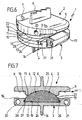
- the inserted hinge insert 4 fills after insertion, the recess 19 and stands with its spherical top 25 upward on the top of the lower part 3, the spherical top 25 dives complementary in the spherical indentation 12 at the bottom of the projection 10 a and there forms with upper part 2 of a ball joint, which allows a certain pivoting of the upper part 2 relative to the lower part 3 (Figure 7).
- the hinge insert 4 can wear on its flat bottom 24 a locking projection 28 which engages elastically when inserting the hinge insert 4 into the lower part 3 in a latching recess 29 which is located at the bottom of the recess 19; Thus, the hinge insert 4 is set in the insertion direction in the recess 19.
- Upper part 2 and lower part 3 are preferably ausverfraglichem Made of metal, for example made of titanium, while the hinge insert 4 is preferably made of a plastic-compatible body material, such as polyethylene.
- These support surfaces 5 and 13 may be formed particularly bone-compatible, for example, this surface can be roughened by a coating, so that there is an optimal anchoring with the adjacent bone material.
Abstract
Description
Die Erfindung betrifft ein Zwischenwirbelimplantat mit einem ersten Teil mit einer Außenfläche, die sich an einem ersten Wirbelkörper abstützt, und einem zweiten Teil mit einer Außenfläche, die sich an einem zweiten Wirbelkörper abstützt, wobei das erste und das zweite Teil so aneinander abgestützt sind, dass eine Beweglichkeit eines Teils relativ zu dem anderen Teil gegeben ist.The invention relates to an intervertebral implant having a first part with an outer surface, which is supported on a first vertebral body, and a second part with an outer surface, which is supported on a second vertebral body, wherein the first and the second part are supported against each other, that a mobility of a part is given relative to the other part.
Ein derartiges Zwischenwirbelimplantat ist beispielsweise aus der
Schwierigkeiten ergeben sich aber auch schon bei zweiteiligen Zwischenwirbelimplantaten insbesondere dann, wenn diese an ihren Stützflächen noch Stifte und andere Vorsprünge tragen, die der Verankerung des Zwischenwirbelimplantates im Knochen dienen sollen. Diese können dann häufig nur dadurch eingesetzt werden, dass der Zwischenwirbelraum stark aufgeweitet wird. Dies ist nicht nur sehr schwierig, sondern birgt auch die Gefahr von Verletzungen in sich.However, difficulties arise even with two-piece intervertebral implants especially when they still carry pins and other projections on their support surfaces, which are intended to anchor the intervertebral implant in the bone. These can then often be used only in that the intervertebral space is greatly expanded. Not only is this very difficult, it also carries the risk of injury.
Da der Zwischenwirbelraum eine relativ geringe Höhe aufweist, ist es auch schwierig, an den beiden Teilen des Zwischenwirbelimplantates Angriffselemente zu befestigen, an denen ein Handhabungsinstrument angreifen kann. Es ist üblich, derartige Handhabungsinstrumente getrennt am Oberteil und am Unterteil angreifen zu lassen, beispielsweise durch Stifte, die in Bohrungen am Oberteil bzw. am Unterteil eingesteckt werden, so dass mit dem Handhabungsinstrument die beiden Teile des Zwischenwirbelimplantates in den Zwischenwirbelraum eingesetzt und gegebenenfalls auch in ihrem Abstand voneinander verändert werden können, so dass dadurch eine gewisse Aufspreizung des Zwischenwirbelraumes möglich ist. Hierzu wird beispielsweise verwiesen auf das zangenförmige Handhabungsinstrument in der
Aufgrund der großen Kräfte ist es notwendig, für die Angriffselemente eine gewisse Bauhöhe vorzusehen, beispielsweise müssen die Aufnahmebohrungen einen bestimmten Durchmesser aufweisen. Daraus ergibt sich eine minimale Bauhöhe für das Oberteil und für das Unterteil, und bei herkömmlichen Zwischenwirbelimplantaten addieren sich somit die Bauhöhen von Oberteil und Unterteil, so dass selbst beim unmittelbaren Aufeinanderliegen von Oberteil und Unterteil eine relativ große Bauhöhe des Zwischenwirbelimplantates unvermeidlich ist.Due to the large forces, it is necessary to provide a certain height for the attack elements, for example, the receiving holes must have a certain diameter. This results in a minimum overall height for the upper part and for the lower part, and in conventional intervertebral implants, the heights of the upper part and lower part, so that even when the upper part and lower part of a direct superimposed relatively large height of the intervertebral implant is inevitable.
Es ist Aufgabe der Erfindung, ein gattungsgemäßes Zwischenwirbelimplantat so auszubilden, dass das Einführen des Zwischenwirbelimplantates in den Zwischenwirbelraum erleichtert wird.It is an object of the invention to form a generic intervertebral implant in such a way that the insertion of the intervertebral implant into the intervertebral space is facilitated.
Erfindungsgemäß wird die Aufgabe durch ein Zwischenwirbelimplantat der im beigefügten Anspruch 1 angegebenen Art gelöst. Weitere vorteilhafte Ausgestaltungen sind in den Unteransprüchen beschrieben.According to the invention the object is achieved by an intervertebral implant specified in the appended
Ferner kann bei einem Zwischenwirbelimplantat der beschriebenen Art vorgesehen sein, dass Oberteil und Unterteil jeweils zum anderen Teil gerichtete Vor- bzw. Rücksprünge aufweisen, die seitlich so gegeneinander versetzt sind, dass sie bei an das Unterteil angenähertem Oberteil ineinander eingreifen, und dass die Angriffselemente am Oberteil und am Unterteil jeweils in Vorsprüngen dieser Teile derart angeordnet sind, dass die Angriffselemente von Oberteil und Unterteil nebeneinander liegen und sich in Richtung der Höhe des Zwischenwirbelimplantats zumindest teilweise überlappen.Furthermore, it can be provided in an intervertebral implant of the type described that upper part and lower part respectively directed to the other part projections or recesses, which are laterally offset from each other so that they interlock with each other in the lower part of the upper part, and that the engagement elements on Upper part and the lower part respectively in projections of these parts are arranged such that the engagement elements of the upper part and lower part are adjacent to each other and overlap at least partially in the direction of the height of the intervertebral implant.
Bei einer solchen Ausgestaltung lässt sich eine minimale Bauhöhe der beiden aufeinanderliegenden zwischenwirbelimplantatsteile erreichen, da die Angriffselemente, die eine minimale Bauhöhe nicht unterschreiten können, jeweils in Vorsprüngen von Oberteil bzw. Unterteil angeordnet sind, also in den Teilen mit der größten Bauhöhe von Oberteil und Unterteil. Diese Bereiche großer Bauhöhen sind als Vorsprünge ausgebildet, neben denen sich jeweils Rücksprünge befinden, in die die Vorsprünge des jeweils anderen Teils eintauchen können. Daraus ergibt sich einmal, dass die Angriffselemente für die Handhabungsinstrumente nebeneinander liegen, und zum anderen, dass diese sich zumindest teilweise überlappen können, so dass die Gesamtbauhöhe der aufeinanderliegenden Teile des Zwischenwirbelimplantates gegenüber herkömmlichen Zwischenwirbelimplantaten deutlich herabgesetzt werden kann. Es ergibt sich somit eine verschachtelte Anordnung von Oberteil und Unterteil mit maximaler Ausnützung der zur Verfügung stehenden Materialhöhe.In such an embodiment, a minimum height of the two superimposed intervertebral implant parts can be achieved because the engagement elements, which can not fall below a minimum height, respectively in projections of upper part or lower part are arranged, ie in the parts with the largest height of upper and lower part , These areas of high heights are formed as projections, adjacent to each recesses are, in which the projections of the other part can dive. This results once that the engagement elements for the handling instruments are adjacent to each other, and secondly that they can overlap at least partially, so that the overall height of the superimposed parts of the intervertebral implant over conventional intervertebral implants can be significantly reduced. This results in a nested arrangement of the upper part and lower part with maximum utilization of the available material height.
Dabei ist es günstig, wenn die Angriffselemente Einstecköffnungen für stiftförmige Halteelemente eines Handhabungsinstrumentes sind, diese Einstecköffnungen können aufgrund der beschriebenen Konstruktion einen relativ großen Durchmesser aufweisen und damit kräftige Haltestifte aufnehmen, und trotzdem ergibt sich eine relativ geringe Bauhöhe des Zwischenwirbelimplantates bei unmittelbar aufeinandergelegten Teilen.It is advantageous if the engagement elements are insertion openings for pin-shaped holding elements of a handling instrument, these insertion openings may have a relatively large diameter due to the construction described and thus absorb strong retaining pins, and still results in a relatively low height of the intervertebral implant in directly superimposed parts.
Dabei ist es vorteilhaft, wenn sich die Einstecköffnungen im wesentlichen parallel zu den Stützflächen erstrecken, auch dadurch wird vermieden, dass die Bauhöhe der Zwischenwirbelimplantatsteile vergrößert wird.It is advantageous if the insertion openings extend substantially parallel to the support surfaces, also thereby avoiding that the height of the intervertebral implant parts is increased.
Bei einer bevorzugten Ausführungsform ist vorgesehen, dass das Unterteil eine der unteren Stützfläche gegenüberliegende zentrale Vertiefung aufweist, die von einem U-förmigen Rand umgeben ist. Die Vertiefung dient also bei unmittelbar aufeinanderliegenden Unterteil und Oberteil der Aufnahme eines Vorsprunges am Oberteil.In a preferred embodiment it is provided that the lower part has a central depression opposite the lower support surface, which is surrounded by a U-shaped edge. The recess thus serves in directly superimposed lower part and upper part of receiving a projection on the upper part.
Dabei ist es vorteilhaft, wenn das Oberteil einen im wesentlichen komplementär in die Vertiefung passenden zentralen Vorsprung trägt, es wird also das gesamte Volumen der Vertiefung für den Vorsprung ausgenutzt.It is advantageous if the upper part carries a substantially complementary complementary in the depression central projection, so it is the entire volume of the recess exploited for the projection.
Es ist weiterhin vorteilhaft, wenn die Angriffselemente des Unterteils an den beiden Enden des U-förmigen Randes angeordnet sind, also außen liegen.It is also advantageous if the engagement elements of the lower part are arranged at the two ends of the U-shaped edge, so are outside.
Die Angriffselemente des Oberteils können dagegen an dem zentralen Vorsprung des Oberteils angeordnet sein, liegen also gegenüber den Angriffselementen des Oberteils weiter innenThe attack elements of the upper part, however, can be arranged on the central projection of the upper part, so are towards the attacking elements of the shell further inside
Insbesondere können die Angriffselemente des Oberteils nahe der seitlichen Ränder des zentralen Vorsprungs angeordnet sein, so dass auch für das Oberteil der Abstand der Angriffselemente relativ groß gewählt werden kann, dadurch lässt sich das Oberteil ebenso wie das Unterteil gegen eine Verkippung zuverlässig sichern.In particular, the engagement elements of the upper part can be arranged close to the lateral edges of the central projection, so that the distance of the engagement elements can be chosen relatively large for the upper part, thus the upper part as well as the lower part can reliably secure against tilting.
Bereits hier sei darauf hingewiesen, dass die Ausdrücke "Unterteil "und "Oberteil" nicht unbedingt etwas über die Einbaulage des Zwischenwirbelimplantates in der Wirbelsäule aussagen, das mit "Unterteil" bezeichnete Teil könnte in der Wirbelsäule tatsächlich auch oben liegen. Wesentlich ist lediglich, dass Oberteil und Unterteil das Zwischenwirbelimplantat auf einander gegenüberliegenden Seiten des Implantates begrenzen.Already here it should be noted that the terms "lower part" and "upper part" do not necessarily say something about the mounting position of the intervertebral implant in the spine, the part called "lower part" could actually be in the spine also up. It is only essential that upper part and lower part limit the intervertebral implant on opposite sides of the implant.
Besonders vorteilhaft ist es, wenn das Oberteil und/oder das Unterteil im wesentlichen plattenförmig ausgebildet sind, wobei diese Teile Vor- und Rücksprünge aufweisen können, die dem jeweils anderen Teil zugewandt sind. Die plattenförmige Ausbildung führt aber insgesamt zu einer sehr geringen Bauhöhe des Zwischenwirbelimplantates.It when the upper part and / or the lower part are formed substantially plate-shaped, wherein these parts may have projections and recesses, which are facing the respective other part is particularly advantageous. Overall, the plate-shaped design leads to a very low overall height of the intervertebral implant.
Bei einer bevorzugten Ausführungsform weisen sowohl das Unterteil als auch das Oberteil je eine Aufnahme für einen Gelenkeinsatz auf. Dieser Gelenkeinsatz, der nach dem Einsetzen des Zwischenwirbelimplantates zwischen Oberteil und Unterteil platziert wird, stützt Oberteil und Unterteil gegeneinander ab, er übernimmt beispielsweise eine federnde Funktion und führt außerdem zu einer gewissen Verschwenkbarkeit der beiden Teile eines Zwischenwirbelimplantates gegeneinander, so dass damit auch eine Verschwenkbarkeit der benachbarten Wirbelkörper erreichbar ist.In a preferred embodiment, both the lower part and the upper part each have a receptacle for a hinge insert. This joint insert, which is placed after insertion of the intervertebral implant between the upper part and lower part, supports upper part and lower part against each other, he takes, for example, a resilient function and also leads to a certain pivotability of the two Parts of an intervertebral implant against each other, so that thus a pivotability of the adjacent vertebrae can be achieved.
Insbesondere ist es vorteilhaft, wenn der Gelenkeinsatz mindestens eine kugelige Stützfläche aufweist, die in die entsprechend kugelig geformte Aufnahme eingreift.In particular, it is advantageous if the hinge insert has at least one spherical support surface, which engages in the corresponding spherical shaped receptacle.
Günstig ist es, wenn die kugelige Aufnahme in einem zentralen Vorsprung des Oberteils angeordnet ist.It is advantageous if the spherical receptacle is arranged in a central projection of the upper part.
Es ist weiterhin vorteilhaft, wenn die zentrale Vertiefung des Unterteils die Aufnahme für den Gelenkeinsatz bildet.It is also advantageous if the central recess of the lower part forms the receptacle for the hinge insert.
Gemäß einer bevorzugten Ausführungsform der Erfindung ist vorgesehen, dass der Gelenkeinsatz von der Seite in die Aufnahme einschiebbar ist, die die Angriffselemente für ein Handhabungsinstrument trägt. Es handelt sich dabei um die Seite, von der Oberteil und Unterteil in den Zwischenwirbelraum eingeführt werden, und von dieser Seite her kann dann auch der Gelenkeinsatz zwischen die bereits eingesetzten Teile des Zwischenwirbelimplantats eingeschoben werden.According to a preferred embodiment of the invention it is provided that the hinge insert is inserted from the side into the receptacle, which carries the engagement elements for a handling instrument. These are the side from which the upper and lower parts are introduced into the intervertebral space, and from this side the joint insert can then also be inserted between the parts of the intervertebral implant already inserted.
Dabei ist es günstig, wenn der Gelenkeinsatz längs einer Führung in die Aufnahme einschiebbar ist.It is advantageous if the hinge insert along a guide into the receptacle can be inserted.
Auch der Einsatz ist vorzugsweise im wesentlichen plattenförmig ausgebildet.The insert is preferably formed substantially plate-shaped.
Eine besonders günstige Ausgestaltung ergibt sich, wenn der Einsatz die zentrale Aufnahme im wesentlichen vollständig ausfüllt und mit der kugeligen Stützfläche aus der Aufnahme hervorsteht.A particularly advantageous embodiment is obtained when the insert substantially completely fills the central receptacle and with the spherical support surface of the recording protrudes.
Die nachfolgende Beschreibung bevorzugter Ausführungsformen der Erfindung dient im Zusammenhang mit der Zeichnung der näheren Erläuterung. Es zeigen:
- Figur 1 : eine perspektivische Explosionsansicht eines Zwischenwirbelimplantates mit einem Oberteil, einem Unterteil und einem zwischen diese einsetzbaren Gelenkeinsatz ;
- Figur 2 : eine perspektivische Explosionsansicht des Oberteils und des Unterteils des Zwischenwirbelimplantates ohne eingesetzten Gelenkeinsatz ;
- Figur 3 : eine Ansicht
ähnlich Figur 2 mit in das Unterteil eingeschobenem Gelenkeinsatz ; - Figur 4 : eine perspektivische Ansicht des Oberteils und des Unterteils des Zwischenwirbelimplantates in maximaler gegenseitiger Annäherung ;
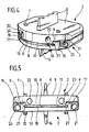
- Figur 5 : eine Vorderansicht des Zwischenwirbelimplantats der
Figur 4; - Figur 6 : eine perspektivische Ansicht des Zwischenwirbelimplantates mit eingesetztem Gelenkeinsatz und
- Figur 7 : eine Querschnittsansicht des Zwischenwirbelimplantats der
Figur 6.
- Figure 1 is an exploded perspective view of an intervertebral implant with an upper part, a lower part and an insertable therebetween hinge insert;
- Figure 2 is an exploded perspective view of the upper part and the lower part of the intervertebral implant without inserted hinge insert;
- Figure 3 is a view similar to Figure 2 with inserted into the lower part joint insert;
- Figure 4 is a perspective view of the upper part and the lower part of the intervertebral implant in maximum mutual approximation;
- FIG. 5: a front view of the intervertebral implant of FIG. 4;
- 6 shows a perspective view of the intervertebral implant with inserted joint insert and
- FIG. 7 shows a cross-sectional view of the intervertebral implant of FIG. 6.
Das in der Zeichnung dargestellte Zwischenwirbelimplantat 1 umfasst drei Teile, nämlich ein plattenförmiges Oberteil 2, ein plattenförmiges Unterteil 3 und einen weitgehend plattenförmig ausgebildeten Gelenkeinsatz 4,The
Das Oberteil 2 ist an seiner Oberseite eben ausgebildet, so dass dadurch eine Stützfläche 5 entsteht, auf der verschiedenartige Vorsprünge 6,7 angeordnet sind, die der Verankerung des Oberteils 2 in einem Wirbelknochen dienen, der mit seiner einem Zwischenwirbelraum zugewandten Endfläche auf der Stützfläche 5 aufliegt.The
Das Oberteil 2 hat einen im wesentlichen rechteckigen Querschnitt, wobei in dem dargestellten Ausführungsbeispiel eine Längskante 8 nach außen gebogen ist.The
An den beiden Schmalseiten dieses Rechteckes ist die Dicke des plattenförmigen Oberteiles 2 kleiner als im zentralen Bereich, so dass sich längs der schmalen Seiten des Oberteils 2 jeweils parallel zu diesen Kanten verlaufende, nach unten weisende Rücksprünge 9 ausbilden, die zur Außenseite hin offen sind. Zwischen den beiden Rücksprüngen 9 befindet sich der zentrale Bereich des Oberteils 2, der somit eine größere Dicke oder Höhe aufweist und somit einen zwischen den beiden Rücksprüngen 9 ausgebildeten, nach unten weisenden Vorsprung 10 ausbildet. Dieser wird durch eine im wesentlichen parallel zur Stützfläche 5 verlaufende Unterseite 11 begrenzt, in der sich eine kugelige Vertiefung 12 befindet, diese bildet eine Lagerschale aus für den Gelenkeinsatz 4.On the two narrow sides of this rectangle, the thickness of the plate-shaped
Das Unterteil 3 des Zwischenwirbelimplantates 1 ist ebenfalls plattenförmig ausgebildet und weist an seiner Unterseite eine ebene Stützfläche 13 mit Vorsprüngen 14 und 15 auf, die den Vorsprüngen 6 und 7 der Stützfläche 5 entsprechen. Auf der der Stützfläche 13 abgewandten Seite ist die Dicke des Unterteils 3 im zentralen Bereich geringer als in einem außenliegenden Bereich.The
Dieser außenliegende Bereich mit größerer Dicke hat die Form eines U mit zwei parallelen Schenkeln 16,17, die parallel zu den schmalkanten des im Querschnitt ähnlich wie das Oberteil 2 ausgebildeten Unterteiles 3 verlaufen, und mit einem die beiden Schenkel 16 und 17 an einer Seite verbindenden Steg 18. Der von den Schenkeln 16 und 17 und dem Steg 18 eingeschlossene Bereich bildet eine zentrale Vertiefung 19, deren Fläche im wesentlichen der Fläche des zentralen Vorsprunges 10 des Oberteils 2 entspricht, während die Anordnung und die Erstreckung der Schenkel 16 und 17 im wesentlichen der Anordnung und Erstreckung der Rücksprünge 9 am Oberteil 2 entsprechen. Es ist dadurch möglich, Oberteil 2 und Unterteil 3 so aufeinanderzulegen, dass der zentrale Vorsprung 10 des Oberteils 2 in die zentrale Vertiefung 19 eintaucht, während die Schenkel 16 und 17 des Unterteils 3 in die Rücksprünge 9 des Oberteils 2 eintauchen (Figur 4), in dieser Stellung sind Oberteil 2 und Unterteil 3 maximal einander angenähert und weisen eine minimale Bauhöhe auf.This outer region of greater thickness has the shape of a U with two
Die Abmessungen sind dabei so gewählt, dass im wesentlichen die jeweiligen Rücksprünge durch die eintauchenden Vorsprünge vollständig ausgefüllt werden.The dimensions are chosen so that substantially the respective recesses are completely filled by the dipping projections.
In die beiden Schenkel 16 und 17 des Unterteils 3 sind von deren freien Enden her parallel zu diesen Schenkeln 16,17 verlaufend Sacklochbohrungen 20 und 21 eingearbeitet, deren Durchmesser im Verhältnis zur Höhe der Schenkel 16,17 relativ groß ist, dieser Durchmesser ist tatsächlich größer als die Dicke oder Höhe des Unterteils 3 im Bereich der zentralen Vertiefung 19.In the two
In den zentralen Vorsprung 10 des Oberteils 2 sind in der Nähe von dessen Seitenkanten Sacklochbohrungen 22 und 23 eingearbeitet, die parallel zu den Sacklochbohrungen 20 und 21 im Unterteil 3 verlaufen. Auch diese Sacklochbohrungen 22 und 23 haben einen relativ großen Durchmesser, der einem wesentlichen Teil der Höhe des Vorsprunges 10 entspricht und größer ist als die Dicke des Oberteils 2 im Bereich der Rücksprünge 9.In the
Wenn Oberteil 2 und Unterteil 3 in der beschriebenen Weise dicht aneinander anliegen, überlappen sich die Sacklochbohrungen 20 und 21 des Unterteils 3 und die Sacklochbohrungen 22 und 23 des Oberteils 2 in Richtung der Höhe des Zwischenwirbelimplantates 1 zumindest teilweise, wie dies aus der Darstellung der Figuren 4 und 5 deutlich wird.If
Die Sacklochbohrungen 20,21,22 und 23 dienen als Aufnahmen für stiftförmige Verlängerungen eines in der Zeichnung nicht dargestellten Handhabungsinstrumentes und bilden somit Angriffselemente für dieses Handhabungsinstrument, welches auf diese Weise getrennt am Oberteil 2 und am Unterteil 3 angreift. Es ist mit diesem Handhabungsinstrument möglich, Oberteil 2 und Unterteil 3 des Zwischenwirbelimplantates 1 in einen Zwischenwirbelraum einzuführen, dabei erleichtert die sehr geringe Bauhöhe des Zwischenwirbelimplantates 1 dieses Einführen, das im wesentlichen ohne große Aufweitung des Zwischenwirbelraumes möglich ist.The
Nach dem Einführen des Oberteils 2 und des Unterteils 3 in dieser Weise können die beiden Teile des Zwischenwirbelimplantates 1 aufgespreizt werden, d. h. ihr Abstand wird beispielsweise mit Hilfe des das Oberteil 2 und das Unterteil 3 haltenden Handhabungsinstrumentes vergrößert.After insertion of the
In dieser aufgespreizten Lage von Oberteil 2 und Unterteil 3 ist es möglich, den Gelenkeinsatz 4 zwischen Oberteil 2 und Unterteil 3 einzuschieben.In this spread position of
Dieser Gelenkeinsatz 4 ist im wesentlichen in Form einer Platte aufgebaut, die eine ebene Unterseite 24 und eine kugelig aufgewölbte Oberseite 25 aufweist. Die Außenabmessungen des plattenförmigen Gelenkeinsatzes 4 entsprechen denen der zentralen Vertiefung 19 im Unterteil 3, so dass der Gelenkeinsatz 4 diese Vertiefung ausfüllend in diese eingeschoben werden kann, und zwar von der Seite her, auf die sich die Sacklochbohrungen 20,21,22,23 öffnen. Dabei greifen Führungsleisten 26 an den Seitenkanten des Gelenkeinsatzes 4 in entsprechende Führungsnuten 27 in den Schenkeln 16,17 ein, so dass eine Einschubführung für den Gelenkeinsatz 4 gebildet wird, die diesen nach dem Einsetzen im Unterteil 3 festlegen. Der eingeschobene Gelenkeinsatz 4 füllt nach dem Einschieben die Vertiefung 19 aus und steht mit seiner kugelig gewölbten Oberseite 25 nach oben über die Oberseite des Unterteiles 3 hervor, die kugelige Oberseite 25 taucht dabei komplementär in die kugelig gewölbte Vertiefung 12 an der Unterseite des Vorsprunges 10 ein und bildet dort mit Oberteil 2 ein Kugelgelenk aus, welches eine gewisse Verschwenkbarkeit des Oberteils 2 gegenüber dem Unterteil 3 ermöglicht (Figur 7).This
Der Gelenkeinsatz 4 kann an seiner ebenen Unterseite 24 einen Rastvorsprung 28 tragen, der beim Einschieben des Gelenkeinsatzes 4 in das Unterteil 3 elastisch in eine Rastausnehmung 29 einrastet, die sich am Boden der Vertiefung 19 befindet ; dadurch wird der Gelenkeinsatz 4 auch in Einschubrichtung in der Vertiefung 19 festgelegt.The
Oberteil 2 und Unterteil 3 sind vorzugsweise aus körperverfraglichem Metall hergestellt, beispielsweise aus Titan, während der Gelenkeinsatz 4 vorzugsweise aus einem ebenfallskörperverträglichen Kunststoffmaterial besteht, beispielsweise aus Polyethylen. Diese Stützflächen 5 bzw. 13 können besonders knochenverträglich ausgebildet sein, beispielsweise kann diese Fläche durch eine Beschichtung aufgerauht werden, so dass sich eine optimale Verankerung mit dem benachbarten Knochenmaterial ergibt.
Claims (29)
Priority Applications (1)
| Application Number | Priority Date | Filing Date | Title |
|---|---|---|---|
| EP07004657.8A EP1795155B1 (en) | 1999-07-02 | 1999-07-02 | Intervertebral implant |
Applications Claiming Priority (4)
| Application Number | Priority Date | Filing Date | Title |
|---|---|---|---|
| DE29911422U DE29911422U1 (en) | 1999-07-02 | 1999-07-02 | Intervertebral implant |
| EP07004657.8A EP1795155B1 (en) | 1999-07-02 | 1999-07-02 | Intervertebral implant |
| PCT/EP1999/004628 WO2001001893A1 (en) | 1999-07-02 | 1999-07-02 | Intervertebral implant |
| EP99931246A EP1194088B1 (en) | 1999-07-02 | 1999-07-02 | Intervertebral implant |
Related Parent Applications (1)
| Application Number | Title | Priority Date | Filing Date |
|---|---|---|---|
| EP99931246A Division EP1194088B1 (en) | 1999-07-02 | 1999-07-02 | Intervertebral implant |
Publications (3)
| Publication Number | Publication Date |
|---|---|
| EP1795155A2 true EP1795155A2 (en) | 2007-06-13 |
| EP1795155A3 EP1795155A3 (en) | 2007-06-27 |
| EP1795155B1 EP1795155B1 (en) | 2014-03-19 |
Family
ID=26062622
Family Applications (2)
| Application Number | Title | Priority Date | Filing Date |
|---|---|---|---|
| EP07004657.8A Expired - Lifetime EP1795155B1 (en) | 1999-07-02 | 1999-07-02 | Intervertebral implant |
| EP99931246A Expired - Lifetime EP1194088B1 (en) | 1999-07-02 | 1999-07-02 | Intervertebral implant |
Family Applications After (1)
| Application Number | Title | Priority Date | Filing Date |
|---|---|---|---|
| EP99931246A Expired - Lifetime EP1194088B1 (en) | 1999-07-02 | 1999-07-02 | Intervertebral implant |
Country Status (13)
| Country | Link |
|---|---|
| US (6) | US6936071B1 (en) |
| EP (2) | EP1795155B1 (en) |
| JP (1) | JP4192262B2 (en) |
| AR (1) | AR024632A1 (en) |
| AT (1) | ATE388677T1 (en) |
| AU (5) | AU780719B2 (en) |
| BR (1) | BR9917397A (en) |
| CA (1) | CA2391330C (en) |
| DE (3) | DE29911422U1 (en) |
| ES (1) | ES2303381T3 (en) |
| MX (1) | MXPA01013413A (en) |
| NZ (1) | NZ516410A (en) |
| WO (1) | WO2001001893A1 (en) |
Families Citing this family (284)
| Publication number | Priority date | Publication date | Assignee | Title |
|---|---|---|---|---|
| US20080215058A1 (en) * | 1997-01-02 | 2008-09-04 | Zucherman James F | Spine distraction implant and method |
| ATE388677T1 (en) | 1999-07-02 | 2008-03-15 | Spine Solutions Inc | INTERVERBARY IMPLANT |
| FR2897259B1 (en) * | 2006-02-15 | 2008-05-09 | Ldr Medical Soc Par Actions Si | INTERSOMATIC TRANSFORAMINAL CAGE WITH INTERBREBAL FUSION GRAFT AND CAGE IMPLANTATION INSTRUMENT |
| DE59914213D1 (en) | 1999-09-14 | 2007-04-05 | Spine Solutions Inc | INSERT INSTRUMENT FOR A INTERMEDIATE IMPLANT |
| US7223291B2 (en) | 2001-07-16 | 2007-05-29 | Spinecore, Inc. | Intervertebral spacer device having engagement hole pairs for manipulation using a surgical tool |
| US8940047B2 (en) | 2001-02-15 | 2015-01-27 | Spinecore, Inc. | Intervertebral spacer device having recessed notch pairs for manipulation using a surgical tool |
| US6673113B2 (en) * | 2001-10-18 | 2004-01-06 | Spinecore, Inc. | Intervertebral spacer device having arch shaped spring elements |
| FR2824261B1 (en) * | 2001-05-04 | 2004-05-28 | Ldr Medical | INTERVERTEBRAL DISC PROSTHESIS AND IMPLEMENTATION METHOD AND TOOLS |
| FR2827156B1 (en) | 2001-07-13 | 2003-11-14 | Ldr Medical | VERTEBRAL CAGE DEVICE WITH MODULAR FASTENING |
| WO2003032802A2 (en) * | 2001-10-18 | 2003-04-24 | Third Millennium Engineering Llc | Intervertebral spacer device having an arched spring element |
| FR2831048B1 (en) | 2001-10-18 | 2004-09-17 | Ldr Medical | PROGRESSIVE APPROACH OSTEOSYNTHESIS DEVICE AND PRE-ASSEMBLY PROCESS |
| FR2831049B1 (en) * | 2001-10-18 | 2004-08-13 | Ldr Medical | PLATE FOR OSTEOSYNTHESIS DEVICE AND PRE-ASSEMBLY METHOD |
| US6740118B2 (en) * | 2002-01-09 | 2004-05-25 | Sdgi Holdings, Inc. | Intervertebral prosthetic joint |
| US7708776B1 (en) * | 2002-01-16 | 2010-05-04 | Nuvasive, Inc. | Intervertebral disk replacement system and methods |
| CA2702131A1 (en) * | 2002-03-11 | 2003-09-25 | Zimmer Spine, Inc. | Instrumentation and procedure for implanting spinal implant devices |
| DE50210270D1 (en) | 2002-03-12 | 2007-07-19 | Cervitech Inc | Intervertebral prosthesis, especially for the cervical spine |
| PL371017A1 (en) | 2002-03-12 | 2005-06-13 | Cervitech, Inc. | Intravertebral prosthesis |
| RU2303422C2 (en) | 2002-03-12 | 2007-07-27 | Сервитек Инк. | Intervertebral prosthesis and system of intervertebral prostheses, in peculiar case, for cervical department of vertebral column |
| EP1344507A1 (en) * | 2002-03-12 | 2003-09-17 | Waldemar Link (GmbH & Co.) | Intervertebral prosthesis for the cervical spine |
| US6824278B2 (en) * | 2002-03-15 | 2004-11-30 | Memx, Inc. | Self-shadowing MEM structures |
| AU2003228391A1 (en) * | 2002-03-30 | 2003-10-20 | Cool Brace | Intervertebral device and method of use |
| CA2451147C (en) * | 2002-04-05 | 2013-07-30 | Nippon Steel Corporation | Pearlitic steel rail excellent in wear resistance and ductility and method for producing the same |
| US8038713B2 (en) | 2002-04-23 | 2011-10-18 | Spinecore, Inc. | Two-component artificial disc replacements |
| US20080027548A9 (en) | 2002-04-12 | 2008-01-31 | Ferree Bret A | Spacerless artificial disc replacements |
| US20030233097A1 (en) * | 2002-04-23 | 2003-12-18 | Ferree Bret A. | Artificial disc replacement (ADR) distraction sleeves and cutting guides |
| US20040030390A1 (en) * | 2002-04-23 | 2004-02-12 | Ferree Bret A. | Intradiscal component installation apparatus and methods |
| US6706068B2 (en) | 2002-04-23 | 2004-03-16 | Bret A. Ferree | Artificial disc replacements with natural kinematics |
| US7179294B2 (en) * | 2002-04-25 | 2007-02-20 | Warsaw Orthopedic, Inc. | Articular disc prosthesis and method for implanting the same |
| US7001433B2 (en) | 2002-05-23 | 2006-02-21 | Pioneer Laboratories, Inc. | Artificial intervertebral disc device |
| US8388684B2 (en) * | 2002-05-23 | 2013-03-05 | Pioneer Signal Technology, Inc. | Artificial disc device |
| GB2389046B (en) * | 2002-05-27 | 2005-10-05 | Biomet Merck Ltd | Spinal prosthesis |
| US6793678B2 (en) * | 2002-06-27 | 2004-09-21 | Depuy Acromed, Inc. | Prosthetic intervertebral motion disc having dampening |
| WO2004016217A2 (en) | 2002-08-15 | 2004-02-26 | David Gerber | Controlled artificial intervertebral disc implant |
| DE10242329B4 (en) * | 2002-09-12 | 2005-03-17 | Biedermann Motech Gmbh | Disc prosthesis |
| DE10242331B4 (en) * | 2002-09-12 | 2005-10-20 | Biedermann Motech Gmbh | Placeholder for vertebral bodies or intervertebral discs |
| WO2004026186A1 (en) * | 2002-09-18 | 2004-04-01 | Mathys Medizinaltechnik Ag | Implant comprising a two-piece joint |
| EP2002805A3 (en) | 2002-09-19 | 2009-01-07 | Malan De Villiers | Intervertebral prosthesis |
| US7833246B2 (en) * | 2002-10-29 | 2010-11-16 | Kyphon SÀRL | Interspinous process and sacrum implant and method |
| EP1555966A4 (en) | 2002-10-29 | 2011-03-16 | Spinecore Inc | Instrumentation, methods, and features for use in implanting an artificial intervertebral disc |
| CA2502292C (en) * | 2002-10-31 | 2011-07-26 | Spinal Concepts, Inc. | Movable disc implant |
| FR2846550B1 (en) * | 2002-11-05 | 2006-01-13 | Ldr Medical | INTERVERTEBRAL DISC PROSTHESIS |
| EP1417940A1 (en) | 2002-11-08 | 2004-05-12 | Waldemar Link (GmbH & Co.) | Vertebral prosthesis |
| US20040098129A1 (en) * | 2002-11-13 | 2004-05-20 | Jo-Wen Lin | Spinal implant insertion adjustment instrument and implants for use therewith |
| US7204852B2 (en) | 2002-12-13 | 2007-04-17 | Spine Solutions, Inc. | Intervertebral implant, insertion tool and method of inserting same |
| GB0301085D0 (en) * | 2003-01-17 | 2003-02-19 | Krishna Manoj | Articulating spinal disc prosthesis |
| US20040186577A1 (en) * | 2003-01-29 | 2004-09-23 | Ferree Bret A. | In situ artificaial disc replacements and other prosthetic components |
| EP2329778A3 (en) * | 2003-01-31 | 2012-06-20 | Spinalmotion, Inc. | Spinal midline indicator |
| JP4275699B2 (en) | 2003-01-31 | 2009-06-10 | スパイナルモーション, インコーポレイテッド | Intervertebral prosthesis placement instrument |
| US20040158254A1 (en) * | 2003-02-12 | 2004-08-12 | Sdgi Holdings, Inc. | Instrument and method for milling a path into bone |
| US7235101B2 (en) * | 2003-09-15 | 2007-06-26 | Warsaw Orthopedic, Inc. | Revisable prosthetic device |
| AU2004212942A1 (en) | 2003-02-14 | 2004-09-02 | Depuy Spine, Inc. | In-situ formed intervertebral fusion device |
| US6908484B2 (en) | 2003-03-06 | 2005-06-21 | Spinecore, Inc. | Cervical disc replacement |
| US7771478B2 (en) | 2003-04-04 | 2010-08-10 | Theken Spine, Llc | Artificial disc prosthesis |
| US8012212B2 (en) | 2003-04-07 | 2011-09-06 | Nuvasive, Inc. | Cervical intervertebral disk prosthesis |
| KR100754570B1 (en) * | 2003-04-07 | 2007-09-05 | 서비텍, 인크. | Prosthetic joint of cervical intervertebral for a cervical spine |
| WO2004089257A1 (en) | 2003-04-14 | 2004-10-21 | Mathys Medizinaltechnik Ag | Intervertebral implant |
| US7491204B2 (en) | 2003-04-28 | 2009-02-17 | Spine Solutions, Inc. | Instruments and method for preparing an intervertebral space for receiving an artificial disc implant |
| EP1514527A3 (en) * | 2003-05-06 | 2005-10-26 | Spinal Innovations, LLC | Artificial intervertebral disc |
| US7291173B2 (en) | 2003-05-06 | 2007-11-06 | Aesculap Ii, Inc. | Artificial intervertebral disc |
| US7105024B2 (en) * | 2003-05-06 | 2006-09-12 | Aesculap Ii, Inc. | Artificial intervertebral disc |
| DE20307876U1 (en) * | 2003-05-19 | 2004-09-23 | Metz-Stavenhagen, Peter, Dr.med. | Device for implantation in a human or animal spine |
| DE20308171U1 (en) * | 2003-05-21 | 2003-07-31 | Aesculap Ag & Co Kg | Vertebral body replacement implant |
| US20090076614A1 (en) * | 2007-09-17 | 2009-03-19 | Spinalmotion, Inc. | Intervertebral Prosthetic Disc with Shock Absorption Core |
| EP2226038A1 (en) | 2003-05-27 | 2010-09-08 | Spinalmotion, Inc. | Prosthetic disc for intervertebral insertion |
| US10052211B2 (en) | 2003-05-27 | 2018-08-21 | Simplify Medical Pty Ltd. | Prosthetic disc for intervertebral insertion |
| US7575599B2 (en) * | 2004-07-30 | 2009-08-18 | Spinalmotion, Inc. | Intervertebral prosthetic disc with metallic core |
| US20040267367A1 (en) | 2003-06-30 | 2004-12-30 | Depuy Acromed, Inc | Intervertebral implant with conformable endplate |
| US7320689B2 (en) * | 2003-07-15 | 2008-01-22 | Cervitech, Inc. | Multi-part cervical endoprosthesis with insertion instrument |
| EP1512384A1 (en) * | 2003-07-21 | 2005-03-09 | Cervitech, Inc. | Intervertebral disc prosthesis |
| US7803162B2 (en) | 2003-07-21 | 2010-09-28 | Spine Solutions, Inc. | Instruments and method for inserting an intervertebral implant |
| JP4299834B2 (en) | 2003-07-22 | 2009-07-22 | ジンテーズ ゲゼルシャフト ミト ベシュレンクテル ハフツング | Intervertebral implant with cap-shaped joint surface |
| AU2003304351B2 (en) * | 2003-07-22 | 2009-05-21 | Synthes Gmbh | Articulated endoprosthesis |
| US7153325B2 (en) * | 2003-08-01 | 2006-12-26 | Ultra-Kinetics, Inc. | Prosthetic intervertebral disc and methods for using the same |
| FR2858546B1 (en) * | 2003-08-04 | 2006-04-28 | Spine Next Sa | INTERVERTEBRAL DISC PROSTHESIS |
| US7753958B2 (en) | 2003-08-05 | 2010-07-13 | Gordon Charles R | Expandable intervertebral implant |
| DE10339170B4 (en) * | 2003-08-22 | 2009-10-15 | Aesculap Ag | Intervertebral implant |
| US7794465B2 (en) * | 2003-09-10 | 2010-09-14 | Warsaw Orthopedic, Inc. | Artificial spinal discs and associated implantation instruments and methods |
| DE10347175B4 (en) * | 2003-10-08 | 2005-10-20 | Aesculap Ag & Co Kg | Intervertebral implant |
| DE10347172B4 (en) * | 2003-10-08 | 2005-09-29 | Aesculap Ag & Co. Kg | Intervertebral implant |
| JP4695717B2 (en) * | 2003-11-03 | 2011-06-08 | イシュラップ インプラント システムズ, インコーポレイテッド | Artificial disc |
| DE50303981D1 (en) * | 2003-11-18 | 2006-08-03 | Zimmer Gmbh | Operating system for inserting disc implants |
| ATE390101T1 (en) | 2003-11-18 | 2008-04-15 | Zimmer Gmbh | DISC IMPLANT |
| US7837732B2 (en) | 2003-11-20 | 2010-11-23 | Warsaw Orthopedic, Inc. | Intervertebral body fusion cage with keels and implantation methods |
| US7670377B2 (en) * | 2003-11-21 | 2010-03-02 | Kyphon Sarl | Laterally insertable artifical vertebral disk replacement implant with curved spacer |
| FR2862866B1 (en) * | 2003-11-28 | 2006-12-15 | Gilles Voydeville | POSTERO-LATERAL INTERVERTEBRAL DISCSTRATE |
| US20050154462A1 (en) * | 2003-12-02 | 2005-07-14 | St. Francis Medical Technologies, Inc. | Laterally insertable artificial vertebral disk replacement implant with translating pivot point |
| US7217291B2 (en) | 2003-12-08 | 2007-05-15 | St. Francis Medical Technologies, Inc. | System and method for replacing degenerated spinal disks |
| DE10361166A1 (en) * | 2003-12-22 | 2005-07-28 | Meisel, Jörg, Dr. | Component for a prosthesis, especially a cervica vertebra, comprises two base parts coupled together by a hinge |
| DE10361957B4 (en) * | 2003-12-23 | 2006-03-02 | Eska Implants Gmbh & Co. | cervical spine implant |
| GB2410189A (en) * | 2004-01-23 | 2005-07-27 | Corin Ltd | Intervertebral disc prosthesis |
| US20050165407A1 (en) * | 2004-01-23 | 2005-07-28 | Diaz Robert L. | Disk arthroplasty instrumentation and implants |
| ES2547532T3 (en) | 2004-02-04 | 2015-10-07 | Ldr Medical | Intervertebral disc prosthesis |
| FR2865629B1 (en) | 2004-02-04 | 2007-01-26 | Ldr Medical | INTERVERTEBRAL DISC PROSTHESIS |
| US7195644B2 (en) * | 2004-03-02 | 2007-03-27 | Joint Synergy, Llc | Ball and dual socket joint |
| US20050209693A1 (en) * | 2004-03-02 | 2005-09-22 | Janzen Lo | Spinal implants |
| US8636802B2 (en) | 2004-03-06 | 2014-01-28 | DePuy Synthes Products, LLC | Dynamized interspinal implant |
| FR2869528B1 (en) * | 2004-04-28 | 2007-02-02 | Ldr Medical | INTERVERTEBRAL DISC PROSTHESIS |
| US20050251261A1 (en) * | 2004-05-05 | 2005-11-10 | Sdgi Holdings, Inc. | Artificial intervertebral disc for lateral insertion |
| US7500972B2 (en) * | 2004-05-07 | 2009-03-10 | Ethicon Endo-Surgery, Inc. | Device for alternately holding, or effecting relative longitudinal movement, of members of a medical instrument |
| DE202004009542U1 (en) * | 2004-06-16 | 2004-08-12 | Aesculap Ag & Co. Kg | Artificial intervertebral disk, comprising core with intensely curved upper and less curved lower surface |
| US8172904B2 (en) * | 2004-06-30 | 2012-05-08 | Synergy Disc Replacement, Inc. | Artificial spinal disc |
| US9237958B2 (en) | 2004-06-30 | 2016-01-19 | Synergy Disc Replacement Inc. | Joint prostheses |
| EP2641571B1 (en) * | 2004-06-30 | 2016-04-13 | Synergy Disc Replacement Inc. | Artificial spinal disc |
| US7585326B2 (en) | 2004-08-06 | 2009-09-08 | Spinalmotion, Inc. | Methods and apparatus for intervertebral disc prosthesis insertion |
| US7854752B2 (en) | 2004-08-09 | 2010-12-21 | Theken Spine, Llc | System and method for dynamic skeletal stabilization |
| PL1857079T3 (en) * | 2004-09-08 | 2010-01-29 | Synthes Gmbh | Universal intervertebral disc prosthesis |
| US7547309B2 (en) | 2004-09-23 | 2009-06-16 | Spine Solutions, Inc. | Distractor for lumbar insertion instrument |
| US7763024B2 (en) | 2004-09-23 | 2010-07-27 | Spine Solutions, Inc. | Adjustable cutting of cutout in vertebral bone |
| NZ554608A (en) * | 2004-09-23 | 2010-07-30 | Spine Solutions Inc | System and method for an intervertebral implant |
| US20060069441A1 (en) * | 2004-09-29 | 2006-03-30 | Zucherman James F | Posterior approach implant method for assembly of multi-piece artificial spinal disk replacement device in situ |
| US7582115B2 (en) * | 2004-09-30 | 2009-09-01 | Helmut Weber | Intervertebral prosthesis |
| US20060085076A1 (en) * | 2004-10-15 | 2006-04-20 | Manoj Krishna | Posterior spinal arthroplasty-development of a new posteriorly inserted artificial disc and an artificial facet joint |
| WO2006042485A1 (en) * | 2004-10-18 | 2006-04-27 | Buettner-Janz Karin | Intervertebral disk endoprosthesis for lumbar and cervical spine, which corresponds to the physiology of movement |
| US20060265074A1 (en) | 2004-10-21 | 2006-11-23 | Manoj Krishna | Posterior spinal arthroplasty-development of a new posteriorly inserted artificial disc, a new anteriorly inserted artifical disc and an artificial facet joint |
| ATE524121T1 (en) | 2004-11-24 | 2011-09-15 | Abdou Samy | DEVICES FOR PLACING AN ORTHOPEDIC INTERVERTEBRAL IMPLANT |
| DE102004059298B3 (en) * | 2004-12-09 | 2006-07-13 | Aesculap Ag & Co. Kg | Kit for an intervertebral implant and intervertebral implant |
| US20060149371A1 (en) * | 2004-12-10 | 2006-07-06 | Sdgi Holdings, Inc. | Intervertebral prosthetic device and method with locking mechanism |
| FR2879436B1 (en) | 2004-12-22 | 2007-03-09 | Ldr Medical | INTERVERTEBRAL DISC PROSTHESIS |
| CH697330B1 (en) | 2004-12-28 | 2008-08-29 | Synthes Gmbh | Intervertebral prosthesis. |
| US8083797B2 (en) | 2005-02-04 | 2011-12-27 | Spinalmotion, Inc. | Intervertebral prosthetic disc with shock absorption |
| ATE531346T1 (en) * | 2005-02-24 | 2011-11-15 | Morphogeny Llc | CONNECTED, SLIDING AND MATCHABLE ROTATABLE COMPONENTS |
| US8496686B2 (en) * | 2005-03-22 | 2013-07-30 | Gmedelaware 2 Llc | Minimally invasive spine restoration systems, devices, methods and kits |
| US8579911B2 (en) | 2008-01-18 | 2013-11-12 | Spinecore, Inc. | Instruments and methods for inserting artificial intervertebral implants |
| US8777959B2 (en) | 2005-05-27 | 2014-07-15 | Spinecore, Inc. | Intervertebral disc and insertion methods therefor |
| US8394142B2 (en) * | 2005-06-13 | 2013-03-12 | Synthes Usa, Llc | Customizing an intervertebral implant |
| EP1736120A1 (en) | 2005-06-22 | 2006-12-27 | Cervitech, Inc. | Intervertebral prosthesis with self-cutting fixation protrusions |
| FR2887435B1 (en) * | 2005-06-24 | 2007-10-05 | Abbott Spine Sa | INTERVERTEBRAL DISC PROSTHESIS |
| FR2887762B1 (en) * | 2005-06-29 | 2007-10-12 | Ldr Medical Soc Par Actions Si | INTERVERTEBRAL DISC PROSTHESIS INSERTION INSTRUMENTATION BETWEEN VERTEBRATES |
| HK1121665A1 (en) | 2005-07-06 | 2009-04-30 | Franz Jun Copf | Intervertebral disc prosthesis |
| EP1903996A2 (en) * | 2005-07-06 | 2008-04-02 | Copf jun., Franz | Intervertebral disc prosthesis |
| FR2891135B1 (en) | 2005-09-23 | 2008-09-12 | Ldr Medical Sarl | INTERVERTEBRAL DISC PROSTHESIS |
| US7867237B2 (en) * | 2005-10-31 | 2011-01-11 | Depuy Spine, Inc. | Arthroplasty revision device and method |
| US7927373B2 (en) * | 2005-10-31 | 2011-04-19 | Depuy Spine, Inc. | Intervertebral disc prosthesis |
| FR2893838B1 (en) * | 2005-11-30 | 2008-08-08 | Ldr Medical Soc Par Actions Si | PROSTHESIS OF INTERVERTEBRAL DISC AND INSTRUMENTATION OF INSERTION OF THE PROSTHESIS BETWEEN VERTEBRATES |
| US8603171B2 (en) * | 2006-01-25 | 2013-12-10 | Mimedx Group, Inc. | Spinal disc implants with flexible keels and methods of fabricating implants |
| US7708777B2 (en) * | 2006-02-03 | 2010-05-04 | Depuy Spine, Inc. | Modular intervertebral disc replacements |
| US8066774B2 (en) | 2006-04-07 | 2011-11-29 | Warsaw Orthopedic, Inc. | Artificial disc implants and associated methods and instrumentation |
| JP2009533187A (en) | 2006-04-12 | 2009-09-17 | スパイナルモーション, インコーポレイテッド | Posterior spine apparatus and method |
| US20080071379A1 (en) * | 2006-05-10 | 2008-03-20 | Mark Rydell | Intervertebral disc replacement |
| US7905906B2 (en) * | 2006-06-08 | 2011-03-15 | Disc Motion Technologies, Inc. | System and method for lumbar arthroplasty |
| US7731752B2 (en) * | 2006-07-21 | 2010-06-08 | Warsaw Orthopedic, Inc. | Implant with nested members and methods of use |
| AU2007276755A1 (en) | 2006-07-24 | 2008-01-31 | Spine Solutions, Inc. | Intervertebral implant with keel |
| US20080051901A1 (en) | 2006-07-28 | 2008-02-28 | Spinalmotion, Inc. | Spinal Prosthesis with Multiple Pillar Anchors |
| US20080051900A1 (en) * | 2006-07-28 | 2008-02-28 | Spinalmotion, Inc. | Spinal Prosthesis with Offset Anchors |
| CA2659024A1 (en) | 2006-07-31 | 2008-02-07 | Synthes (Usa) | Drilling/milling guide and keel cut preparation system |
| US7976550B2 (en) * | 2006-08-10 | 2011-07-12 | Pioneer Surgical Technology | Insertion instrument for artificial discs |
| US8409213B2 (en) * | 2006-08-10 | 2013-04-02 | Pioneer Surgical Technology, Inc. | Insertion instrument for artificial discs |
| US8118872B2 (en) * | 2006-08-10 | 2012-02-21 | Pioneer Surgical Technology, Inc. | System and methods for inserting a spinal disc device into an intervertebral space |
| US8906096B2 (en) | 2006-08-15 | 2014-12-09 | GMFDelaware 2 LLC | Spinal implant |
| EP2073762B1 (en) * | 2006-08-22 | 2011-04-06 | Synthes GmbH | Total disc replacement device |
| US8057545B2 (en) | 2006-08-25 | 2011-11-15 | Warsaw Orthopedic, Inc. | Revision spacer |
| US8414616B2 (en) * | 2006-09-12 | 2013-04-09 | Pioneer Surgical Technology, Inc. | Mounting devices for fixation devices and insertion instruments used therewith |
| US8715350B2 (en) | 2006-09-15 | 2014-05-06 | Pioneer Surgical Technology, Inc. | Systems and methods for securing an implant in intervertebral space |
| US8597357B2 (en) * | 2006-09-15 | 2013-12-03 | Pioneer Surgical Technology, Inc. | System and method for sizing, inserting and securing artificial disc in intervertebral space |
| US8377133B2 (en) | 2006-09-15 | 2013-02-19 | Pioneer Surgical Technology, Inc. | Systems and methods for sizing, inserting and securing an implant in intervertebral space |
| EP2063817A4 (en) | 2006-09-15 | 2012-04-18 | Pioneer Surgical Technology Inc | Joint arthroplasty devices having articulating members |
| US8372084B2 (en) * | 2006-09-22 | 2013-02-12 | Pioneer Surgical Technology, Inc. | System and methods for inserting a spinal disc device into an intervertebral space |
| US20080114453A1 (en) * | 2006-11-13 | 2008-05-15 | Warsaw Orthopedic, Inc. | Intervertebral prosthetic devices and surgical methods |
| US8092534B2 (en) | 2006-11-16 | 2012-01-10 | Warsaw Orthopedic, Inc. | Revision device |
| US20080140204A1 (en) * | 2006-12-07 | 2008-06-12 | Warsaw Orthopedic, Inc. | Vertebral Implant Systems and Methods of Use |
| US9867640B2 (en) * | 2006-12-07 | 2018-01-16 | Nexus Spine, LLC | Press-on pedicle screw assembly |
| US8105382B2 (en) | 2006-12-07 | 2012-01-31 | Interventional Spine, Inc. | Intervertebral implant |
| US8715352B2 (en) | 2006-12-14 | 2014-05-06 | Depuy Spine, Inc. | Buckling disc replacement |
| US20080154378A1 (en) * | 2006-12-22 | 2008-06-26 | Warsaw Orthopedic, Inc. | Bone implant having engineered surfaces |
| US20080161932A1 (en) * | 2006-12-27 | 2008-07-03 | Kevin Armstrong | Artificial Disc |
| US20080161921A1 (en) * | 2006-12-29 | 2008-07-03 | Warsaw Orthopedic, Inc. | Spinal Prosthesis Systems |
| CA2675222A1 (en) * | 2007-01-12 | 2008-07-24 | Synthes Usa, Llc | Modular intervertebral implant |
| US7959677B2 (en) | 2007-01-19 | 2011-06-14 | Flexuspine, Inc. | Artificial functional spinal unit system and method for use |
| US8034081B2 (en) | 2007-02-06 | 2011-10-11 | CollabComl, LLC | Interspinous dynamic stabilization implant and method of implanting |
| US9314346B2 (en) * | 2007-02-12 | 2016-04-19 | Brigham Young University | Spinal implant |
| US8308801B2 (en) * | 2007-02-12 | 2012-11-13 | Brigham Young University | Spinal implant |
| US9138263B2 (en) | 2007-02-14 | 2015-09-22 | William R. Krause | Flexible spine components |
| US8465546B2 (en) | 2007-02-16 | 2013-06-18 | Ldr Medical | Intervertebral disc prosthesis insertion assemblies |
| US20080228276A1 (en) * | 2007-03-14 | 2008-09-18 | Warsaw Orthopedic, Inc. | Intervertebral Prosthesis, Instruments, and Methods of Implanting |
| US20080228275A1 (en) * | 2007-03-14 | 2008-09-18 | Heather Cannon | Intervertebral implant component with three points of contact |
| DE102007024262B4 (en) | 2007-05-23 | 2017-01-26 | Janos Borgulya | Intervertebral disc prosthesis and instrument cluster with a disc prosthesis |
| FR2916956B1 (en) | 2007-06-08 | 2012-12-14 | Ldr Medical | INTERSOMATIC CAGE, INTERVERTEBRAL PROSTHESIS, ANCHORING DEVICE AND IMPLANTATION INSTRUMENTATION |
| US10821003B2 (en) | 2007-06-20 | 2020-11-03 | 3Spline Sezc | Spinal osteotomy |
| US8900307B2 (en) | 2007-06-26 | 2014-12-02 | DePuy Synthes Products, LLC | Highly lordosed fusion cage |
| US20090043391A1 (en) | 2007-08-09 | 2009-02-12 | Spinalmotion, Inc. | Customized Intervertebral Prosthetic Disc with Shock Absorption |
| US8231676B2 (en) * | 2007-09-17 | 2012-07-31 | Pioneer Surgical Technology, Inc. | Motion preserving artificial intervertebral disc device |
| WO2009055481A1 (en) | 2007-10-22 | 2009-04-30 | Spinalmotion, Inc. | Dynamic spacer device and method for spanning a space formed upon removal of an intervertebral disc |
| EP2211785B1 (en) | 2007-10-25 | 2016-01-27 | Synergy Disc Replacement, Inc. | Systems for vertebral disc replacement |
| US8758439B2 (en) | 2007-11-19 | 2014-06-24 | Linares Medical Devices, Llc | Spine support implant including inter vertebral insertable fluid ballastable insert and inter-vertebral web retaining harnesses |
| US20090131984A1 (en) * | 2007-11-19 | 2009-05-21 | Linares Miguel A | Spine support implant including inter vertebral insertable fluid ballastable insert and inter-vertebral web retaining harnesses |
| US8888850B2 (en) * | 2007-11-19 | 2014-11-18 | Linares Medical Devices, Llc | Combination spacer insert and support for providing inter-cervical vertebral support |
| US8894687B2 (en) | 2011-04-25 | 2014-11-25 | Nexus Spine, L.L.C. | Coupling system for surgical construct |
| US9232965B2 (en) * | 2009-02-23 | 2016-01-12 | Nexus Spine, LLC | Press-on link for surgical screws |
| US8118873B2 (en) * | 2008-01-16 | 2012-02-21 | Warsaw Orthopedic, Inc. | Total joint replacement |
| EP2471493A1 (en) | 2008-01-17 | 2012-07-04 | Synthes GmbH | An expandable intervertebral implant and associated method of manufacturing the same |
| US8764833B2 (en) | 2008-03-11 | 2014-07-01 | Spinalmotion, Inc. | Artificial intervertebral disc with lower height |
| US20090248161A1 (en) * | 2008-03-20 | 2009-10-01 | K2M, Inc. | Artificial disc replacement device |
| BRPI0910325A8 (en) | 2008-04-05 | 2019-01-29 | Synthes Gmbh | expandable intervertebral implant |
| US9034038B2 (en) | 2008-04-11 | 2015-05-19 | Spinalmotion, Inc. | Motion limiting insert for an artificial intervertebral disc |
| KR20110009216A (en) | 2008-05-05 | 2011-01-27 | 스피날모우션, 인코포레이티드 | Polyaryletherketone artificial intervertebral disc |
| US9220603B2 (en) | 2008-07-02 | 2015-12-29 | Simplify Medical, Inc. | Limited motion prosthetic intervertebral disc |
| WO2010000766A2 (en) * | 2008-07-03 | 2010-01-07 | Ceramtec Ag | Intervertebral disc endoprosthesis |
| EP2299944A4 (en) | 2008-07-17 | 2013-07-31 | Spinalmotion Inc | Artificial intervertebral disc placement system |
| WO2010009153A1 (en) | 2008-07-18 | 2010-01-21 | Spinalmotion, Inc. | Posterior prosthetic intervertebral disc |
| DE102008048739A1 (en) * | 2008-09-24 | 2010-04-01 | Franz Dr. Copf jun. | Disc prosthesis |
| US8147554B2 (en) | 2008-10-13 | 2012-04-03 | Globus Medical, Inc. | Intervertebral spacer |
| US8545566B2 (en) * | 2008-10-13 | 2013-10-01 | Globus Medical, Inc. | Articulating spacer |
| US8308804B2 (en) * | 2008-11-14 | 2012-11-13 | David Krueger | Spinal fusion device |
| JP5681639B2 (en) | 2008-12-22 | 2015-03-11 | ジンテス ゲゼルシャフト ミット ベシュレンクテル ハフツング | Orthopedic implant with flexible keel |
| US20100158209A1 (en) * | 2008-12-22 | 2010-06-24 | General Instrument Corporation | Access to Network Based on Automatic Speech-Recognition |
| CN102325508A (en) * | 2009-02-19 | 2012-01-18 | 安东·E·鲍登 | The dynamic type spinal implant of compliance |
| US9526620B2 (en) | 2009-03-30 | 2016-12-27 | DePuy Synthes Products, Inc. | Zero profile spinal fusion cage |
| US8500801B2 (en) | 2009-04-21 | 2013-08-06 | Medtronic, Inc. | Stents for prosthetic heart valves and methods of making same |
| US20110040331A1 (en) * | 2009-05-20 | 2011-02-17 | Jose Fernandez | Posterior stabilizer |
| CN105342683B (en) | 2009-07-06 | 2018-02-13 | 斯恩蒂斯有限公司 | Expandable fixation assemblies |
| US8617245B2 (en) | 2009-09-17 | 2013-12-31 | DePuy Synthes Products, LLC | Intervertebral implant having extendable bone fixation members |
| US9157497B1 (en) | 2009-10-30 | 2015-10-13 | Brigham Young University | Lamina emergent torsional joint and related methods |
| US8764806B2 (en) | 2009-12-07 | 2014-07-01 | Samy Abdou | Devices and methods for minimally invasive spinal stabilization and instrumentation |
| US9393129B2 (en) | 2009-12-10 | 2016-07-19 | DePuy Synthes Products, Inc. | Bellows-like expandable interbody fusion cage |
| US9833331B2 (en) | 2009-12-31 | 2017-12-05 | Ldr Medical | Anchoring device and system for an intervertebral implant, intervertebral implant and implantation instrument |
| BR112012019085A2 (en) * | 2010-02-22 | 2016-09-13 | Synthes Gmbh | full disk replacement with w-shaped spring elements. |
| KR101699577B1 (en) | 2010-04-09 | 2017-01-24 | 신세스 게엠바하 | Endplate of an intervertevral implant and implant |
| US9301853B2 (en) | 2010-04-09 | 2016-04-05 | DePuy Synthes Products, Inc. | Holder for implantation and extraction of prosthesis |
| US8858636B2 (en) | 2010-04-09 | 2014-10-14 | DePuy Synthes Products, LLC | Intervertebral implant |
| CN102232880A (en) * | 2010-04-23 | 2011-11-09 | 蒋秀英 | Artificial intervertebral disk |
| CN101828979B (en) * | 2010-04-29 | 2011-12-21 | 杨晋才 | Artificial cervical vertebral body and intervertebral disc composite body |
| US8979860B2 (en) | 2010-06-24 | 2015-03-17 | DePuy Synthes Products. LLC | Enhanced cage insertion device |
| US9282979B2 (en) | 2010-06-24 | 2016-03-15 | DePuy Synthes Products, Inc. | Instruments and methods for non-parallel disc space preparation |
| EP2588034B1 (en) | 2010-06-29 | 2018-01-03 | Synthes GmbH | Distractible intervertebral implant |
| US9402732B2 (en) | 2010-10-11 | 2016-08-02 | DePuy Synthes Products, Inc. | Expandable interspinous process spacer implant |
| US8496713B2 (en) | 2010-12-10 | 2013-07-30 | Globus Medical, Inc. | Spine stabilization device and methods |
| WO2012094647A2 (en) | 2011-01-06 | 2012-07-12 | Bergey Darren L | Interbody vertebral prosthetic device with blade anchor |
| US11701238B2 (en) | 2011-01-06 | 2023-07-18 | Darren L. BERGEY | Compressive, orthopedic, anchoring apparatus and method |
| US9084683B2 (en) | 2011-01-07 | 2015-07-21 | Pbn Spinal Implants, Llc | Spinal implant system and method |
| US8998991B2 (en) * | 2011-02-23 | 2015-04-07 | Globus Medical, Inc. | Six degree spine stabilization devices and methods |
| WO2012125382A1 (en) | 2011-03-11 | 2012-09-20 | FBC Device ApS | Spinal implant, instrument for preparation and method of use |
| US8388687B2 (en) | 2011-03-25 | 2013-03-05 | Flexuspine, Inc. | Interbody device insertion systems and methods |
| US9622759B2 (en) | 2011-04-21 | 2017-04-18 | DePuy Synthes Products, Inc. | Spline oriented indexing guide |
| RU2578177C2 (en) | 2011-05-18 | 2016-03-20 | Ульрих Гмбх Энд Ко. Кг | Artificial disc replacement |
| WO2012177412A2 (en) | 2011-06-07 | 2012-12-27 | Brigham Young University | Serpentine spinal stability device and associated methods |
| US8845728B1 (en) | 2011-09-23 | 2014-09-30 | Samy Abdou | Spinal fixation devices and methods of use |
| US9017410B2 (en) | 2011-10-26 | 2015-04-28 | Globus Medical, Inc. | Artificial discs |
| US9526627B2 (en) | 2011-11-17 | 2016-12-27 | Exactech, Inc. | Expandable interbody device system and method |
| US9198769B2 (en) | 2011-12-23 | 2015-12-01 | Pioneer Surgical Technology, Inc. | Bone anchor assembly, bone plate system, and method |
| US9125753B2 (en) | 2012-02-17 | 2015-09-08 | Ervin Caballes | Elastomeric artificial joints and intervertebral prosthesis systems |
| US20130226240A1 (en) | 2012-02-22 | 2013-08-29 | Samy Abdou | Spinous process fixation devices and methods of use |
| FR2987256B1 (en) | 2012-02-24 | 2014-08-08 | Ldr Medical | ANCHORING DEVICE FOR INTERVERTEBRAL IMPLANT, INTERVERTEBRAL IMPLANT AND IMPLANTATION INSTRUMENTATION |
| US8940052B2 (en) | 2012-07-26 | 2015-01-27 | DePuy Synthes Products, LLC | Expandable implant |
| US9198767B2 (en) | 2012-08-28 | 2015-12-01 | Samy Abdou | Devices and methods for spinal stabilization and instrumentation |
| US20140067069A1 (en) * | 2012-08-30 | 2014-03-06 | Interventional Spine, Inc. | Artificial disc |
| US9320617B2 (en) | 2012-10-22 | 2016-04-26 | Cogent Spine, LLC | Devices and methods for spinal stabilization and instrumentation |
| US9492288B2 (en) | 2013-02-20 | 2016-11-15 | Flexuspine, Inc. | Expandable fusion device for positioning between adjacent vertebral bodies |
| US9717601B2 (en) | 2013-02-28 | 2017-08-01 | DePuy Synthes Products, Inc. | Expandable intervertebral implant, system, kit and method |
| US9522070B2 (en) | 2013-03-07 | 2016-12-20 | Interventional Spine, Inc. | Intervertebral implant |
| FR3005569B1 (en) | 2013-05-16 | 2021-09-03 | Ldr Medical | VERTEBRAL IMPLANT, VERTEBRAL IMPLANT FIXATION DEVICE AND IMPLANTATION INSTRUMENTATION |
| US9198770B2 (en) | 2013-07-31 | 2015-12-01 | Globus Medical, Inc. | Artificial disc devices and related methods of use |
| US9517144B2 (en) | 2014-04-24 | 2016-12-13 | Exactech, Inc. | Limited profile intervertebral implant with incorporated fastening mechanism |
| US10398565B2 (en) | 2014-04-24 | 2019-09-03 | Choice Spine, Llc | Limited profile intervertebral implant with incorporated fastening and locking mechanism |
| FR3020756B1 (en) | 2014-05-06 | 2022-03-11 | Ldr Medical | VERTEBRAL IMPLANT, VERTEBRAL IMPLANT FIXATION DEVICE AND IMPLANT INSTRUMENTATION |
| JP6573908B2 (en) | 2014-05-12 | 2019-09-11 | インテグラ・ライフサイエンシーズ・コーポレイションIntegra LifeSciences Corporation | Total joint replacement prosthesis |
| US9642651B2 (en) | 2014-06-12 | 2017-05-09 | Brigham Young University | Inverted serpentine spinal stability device and associated methods |
| AU2014331640B2 (en) * | 2014-11-07 | 2017-02-16 | Wright Medical Technology, Inc | Talar dome fixation stem |
| US11426290B2 (en) | 2015-03-06 | 2022-08-30 | DePuy Synthes Products, Inc. | Expandable intervertebral implant, system, kit and method |
| US9913727B2 (en) | 2015-07-02 | 2018-03-13 | Medos International Sarl | Expandable implant |
| CN105030388A (en) * | 2015-08-19 | 2015-11-11 | 深圳清华大学研究院 | Lumbar intervertebral disc prosthesis, implanting instrument, device composed of waist prosthesis and implanting instrument and method for inserting lumbar vertebra implantation material |
| CN105105889B (en) * | 2015-08-31 | 2017-11-10 | 深圳清华大学研究院 | A kind of artificial lumbar disc prostheses |
| US10857003B1 (en) | 2015-10-14 | 2020-12-08 | Samy Abdou | Devices and methods for vertebral stabilization |
| US11596522B2 (en) | 2016-06-28 | 2023-03-07 | Eit Emerging Implant Technologies Gmbh | Expandable and angularly adjustable intervertebral cages with articulating joint |
| US11510788B2 (en) | 2016-06-28 | 2022-11-29 | Eit Emerging Implant Technologies Gmbh | Expandable, angularly adjustable intervertebral cages |
| US10744000B1 (en) | 2016-10-25 | 2020-08-18 | Samy Abdou | Devices and methods for vertebral bone realignment |
| US10973648B1 (en) | 2016-10-25 | 2021-04-13 | Samy Abdou | Devices and methods for vertebral bone realignment |
| US10537436B2 (en) | 2016-11-01 | 2020-01-21 | DePuy Synthes Products, Inc. | Curved expandable cage |
| RU2636852C1 (en) * | 2016-12-05 | 2017-11-28 | Федеральное государственное бюджетное учреждение науки Институт физики прочности и материаловедения Сибирского отделения Российской академии наук (ИФПМ СО РАН) | Intervertebral disk endoprosthesis |
| US10888433B2 (en) | 2016-12-14 | 2021-01-12 | DePuy Synthes Products, Inc. | Intervertebral implant inserter and related methods |
| CN107049563B (en) * | 2017-04-19 | 2020-02-07 | 北京爱康宜诚医疗器材有限公司 | Intervertebral disc prosthesis |
| US10398563B2 (en) | 2017-05-08 | 2019-09-03 | Medos International Sarl | Expandable cage |
| US11344424B2 (en) | 2017-06-14 | 2022-05-31 | Medos International Sarl | Expandable intervertebral implant and related methods |
| US10940016B2 (en) | 2017-07-05 | 2021-03-09 | Medos International Sarl | Expandable intervertebral fusion cage |
| JP2020533070A (en) | 2017-09-08 | 2020-11-19 | パイオニア サージカル テクノロジー インコーポレイテッド | Intervertebral implants, instruments, and methods |
| USD907771S1 (en) | 2017-10-09 | 2021-01-12 | Pioneer Surgical Technology, Inc. | Intervertebral implant |
| CN108969160B (en) * | 2018-07-27 | 2021-07-30 | 深圳清华大学研究院 | Intervertebral motion retaining device and integrated implantation instrument and implantation method thereof |
| CN108969162A (en) * | 2018-07-27 | 2018-12-11 | 深圳清华大学研究院 | A kind of intervertebral motion retaining device |
| US11179248B2 (en) | 2018-10-02 | 2021-11-23 | Samy Abdou | Devices and methods for spinal implantation |
| US11446156B2 (en) | 2018-10-25 | 2022-09-20 | Medos International Sarl | Expandable intervertebral implant, inserter instrument, and related methods |
| US11878133B2 (en) | 2019-10-08 | 2024-01-23 | Medtronic, Inc. | Methods of preparing balloon expandable catheters for cardiac and vascular interventions |
| US11291553B2 (en) * | 2020-03-05 | 2022-04-05 | Phoenyx Spinal Technologies, Inc. | Interlocking spinal disc prosthetic |
| US11426286B2 (en) | 2020-03-06 | 2022-08-30 | Eit Emerging Implant Technologies Gmbh | Expandable intervertebral implant |
| US11850160B2 (en) | 2021-03-26 | 2023-12-26 | Medos International Sarl | Expandable lordotic intervertebral fusion cage |
| US11752009B2 (en) | 2021-04-06 | 2023-09-12 | Medos International Sarl | Expandable intervertebral fusion cage |
Citations (6)
| Publication number | Priority date | Publication date | Assignee | Title |
|---|---|---|---|---|
| DE3023353A1 (en) | 1979-10-03 | 1981-04-09 | Gebrüder Sulzer AG, 8401 Winterthur | INTERMEDIATE TURBINE TOTAL PROSTHESIS |
| EP0317572A1 (en) | 1986-07-31 | 1989-05-31 | The General Hospital Corporation | Method of preparing peracetyl oxazolines |
| EP0333990A2 (en) | 1988-03-23 | 1989-09-27 | Waldemar Link (GmbH & Co.) | Surgical instrument set |
| WO1993010725A2 (en) | 1991-12-04 | 1993-06-10 | Customflex Limited | Improvements in or relating to spinal vertebrae implants |
| EP0560141A1 (en) | 1992-03-13 | 1993-09-15 | Waldemar Link (GmbH & Co.) | Intervertebral disc endoprosthesis |
| US5314477A (en) | 1990-03-07 | 1994-05-24 | J.B.S. Limited Company | Prosthesis for intervertebral discs and instruments for implanting it |
Family Cites Families (298)
| Publication number | Priority date | Publication date | Assignee | Title |
|---|---|---|---|---|
| US114816A (en) | 1871-05-16 | Improvement in carriage-jacks | ||
| GB1030145A (en) | 1964-04-21 | 1966-05-18 | Paul Wittebol | Improvements in or relating to femoral prostheses |
| US3486505A (en) | 1967-05-22 | 1969-12-30 | Gordon M Morrison | Orthopedic surgical instrument |
| US3510883A (en) | 1967-10-30 | 1970-05-12 | Robert F Cathcart | Joint prosthesis |
| BE757681A (en) | 1970-01-22 | 1971-04-01 | Sampson Arnold | IMPROVEMENTS TO DENTAL PROSTHESIS DEVICES |
| US3740769A (en) | 1971-02-11 | 1973-06-26 | E Haboush | Prosthesis for hip joints |
| DE2263842A1 (en) | 1972-12-28 | 1974-07-04 | Hoffmann Daimler Siegfried Dr | DISC PROTHESIS |
| JPS552966Y2 (en) | 1974-02-08 | 1980-01-24 | ||
| US3875595A (en) | 1974-04-15 | 1975-04-08 | Edward C Froning | Intervertebral disc prosthesis and instruments for locating same |
| US3903549A (en) | 1974-06-12 | 1975-09-09 | William Minor Deyerle | Acetabular cup prosthesis component for total or subtotal hip prosthesis system |
| GB1522603A (en) | 1974-08-07 | 1978-08-23 | Nat Res Dev | Prosthetic devices |
| USD243286S (en) | 1975-06-02 | 1977-02-01 | William Minor Deyerle | Femoral hip prosthesis component for total and sub-total hip replacement systems |
| US4034746A (en) | 1975-08-01 | 1977-07-12 | Williams Robert W | Retractor |
| US4038897A (en) | 1975-10-14 | 1977-08-02 | Electronic Music Laboratories, Inc. | Electronic music system and stringed instrument input device therefor |
| US4021864A (en) * | 1976-04-14 | 1977-05-10 | The Regents Of The University Of California | Ankle prosthesis |
| GB1579773A (en) * | 1977-07-18 | 1980-11-26 | Nat Res Dev | Endoprosthetic bone joint devices |
| CH624573A5 (en) | 1978-02-01 | 1981-08-14 | Sulzer Ag | Intervertebral prosthesis |
| US4470158A (en) | 1978-03-10 | 1984-09-11 | Biomedical Engineering Corp. | Joint endoprosthesis |
| DE3012447C2 (en) | 1980-03-31 | 1982-04-01 | Harald 7200 Tuttlingen Maslanka | Surgical grasper instrument |
| CA1146301A (en) | 1980-06-13 | 1983-05-17 | J. David Kuntz | Intervertebral disc prosthesis |
| US4309777A (en) | 1980-11-13 | 1982-01-12 | Patil Arun A | Artificial intervertebral disc |
| EP0077159A1 (en) | 1981-10-14 | 1983-04-20 | Brian Norman Atkins | Vertebrae spreader |
| US4770661A (en) | 1982-01-18 | 1988-09-13 | Indong Oh | Conversion femoral endoprosthesis |
| US4545374A (en) | 1982-09-03 | 1985-10-08 | Jacobson Robert E | Method and instruments for performing a percutaneous lumbar diskectomy |
| US4681589A (en) | 1984-06-01 | 1987-07-21 | Tronzo Raymond G | Adjustable acetabular cup prosthesis as part of a total cup replacement system |
| US4736738A (en) | 1984-07-09 | 1988-04-12 | Matej Lipovsek | Instrument kit and procedure for performing posterior lumbar interbody fusion |
| US4550450A (en) | 1984-07-24 | 1985-11-05 | Kinnett James G | Total shoulder prosthesis system |
| EP0176728B1 (en) | 1984-09-04 | 1989-07-26 | Humboldt-Universität zu Berlin | Intervertebral-disc prosthesis |
| US4622959A (en) | 1985-03-05 | 1986-11-18 | Marcus Randall E | Multi-use femoral intramedullary nail |
| DE3526742A1 (en) | 1985-07-26 | 1987-01-29 | Volkmar Dipl Ing Jansson | Guide sleeve with a striker for driving (bone) chips in bone |
| US4653487A (en) | 1986-01-29 | 1987-03-31 | Maale Gerhard E | Intramedullary rod assembly for cement injection system |
| US4697586A (en) | 1986-06-24 | 1987-10-06 | Gazale William J | Combined chisel-guide surgical instrument |
| GB8620937D0 (en) | 1986-08-29 | 1986-10-08 | Shepperd J A N | Spinal implant |
| CA1283501C (en) | 1987-02-12 | 1991-04-30 | Thomas P. Hedman | Artificial spinal disc |
| US4714469A (en) | 1987-02-26 | 1987-12-22 | Pfizer Hospital Products Group, Inc. | Spinal implant |
| JPH01136655A (en) | 1987-11-24 | 1989-05-29 | Asahi Optical Co Ltd | Movable type pyramid spacer |
| US4805607A (en) | 1987-12-03 | 1989-02-21 | Boehringer Mannheim Corporation | Modular intramedullary nail system |
| US4874389A (en) * | 1987-12-07 | 1989-10-17 | Downey Ernest L | Replacement disc |
| US4875474A (en) | 1988-01-29 | 1989-10-24 | Biomet, Inc. | Variable wall thickness interlocking intramedullary nail |
| US4936863A (en) | 1988-05-13 | 1990-06-26 | Hofmann Aaron A | Hip prosthesis |
| DE8807485U1 (en) | 1988-06-06 | 1989-08-10 | Mecron Medizinische Produkte Gmbh, 1000 Berlin, De | |
| CN1128944A (en) | 1988-06-13 | 1996-08-14 | 卡林技术公司 | Apparatus and method of inserting spinal implants |
| US5015247A (en) | 1988-06-13 | 1991-05-14 | Michelson Gary K | Threaded spinal implant |
| US6770074B2 (en) | 1988-06-13 | 2004-08-03 | Gary Karlin Michelson | Apparatus for use in inserting spinal implants |
| US5484437A (en) | 1988-06-13 | 1996-01-16 | Michelson; Gary K. | Apparatus and method of inserting spinal implants |
| CA1333209C (en) | 1988-06-28 | 1994-11-29 | Gary Karlin Michelson | Artificial spinal fusion implants |
| US4892545A (en) * | 1988-07-14 | 1990-01-09 | Ohio Medical Instrument Company, Inc. | Vertebral lock |
| US5545229A (en) * | 1988-08-18 | 1996-08-13 | University Of Medicine And Dentistry Of Nj | Functional and biocompatible intervertebral disc spacer containing elastomeric material of varying hardness |
| US4936853A (en) | 1989-01-11 | 1990-06-26 | Kirschner Medical Corporation | Modular knee prosthesis |
| US5022576A (en) | 1989-01-13 | 1991-06-11 | Jenq Jin Huoo | Lever-operated protective cover for a saw tooth-shaped cutter |
| CA1318469C (en) | 1989-02-15 | 1993-06-01 | Acromed Corporation | Artificial disc |
| JPH02261446A (en) * | 1989-04-03 | 1990-10-24 | Kawasaki Steel Corp | Artificial vertebra |
| DE3921973C1 (en) | 1989-07-04 | 1990-10-31 | Rainer Dr. 8000 Muenchen De Baumgart | |
| US5037438A (en) | 1989-07-25 | 1991-08-06 | Richards Medical Company | Zirconium oxide coated prosthesis for wear and corrosion resistance |
| US4932975A (en) | 1989-10-16 | 1990-06-12 | Vanderbilt University | Vertebral prosthesis |
| DE8912648U1 (en) * | 1989-10-23 | 1990-11-22 | Mecron Medizinische Produkte Gmbh, 1000 Berlin, De | |
| US5004476A (en) | 1989-10-31 | 1991-04-02 | Tulane University | Porous coated total hip replacement system |
| US5062850A (en) | 1990-01-16 | 1991-11-05 | University Of Florida | Axially-fixed vertebral body prosthesis and method of fixation |
| US5236460A (en) | 1990-02-12 | 1993-08-17 | Midas Rex Pneumatic Tools, Inc. | Vertebral body prosthesis |
| EP0453393B1 (en) | 1990-04-20 | 1993-10-06 | SULZER Medizinaltechnik AG | Implant, particularly intervertebral prosthesis |
| US6006174A (en) | 1990-10-03 | 1999-12-21 | Interdigital Technology Coporation | Multiple impulse excitation speech encoder and decoder |
| US5336232A (en) | 1991-03-14 | 1994-08-09 | United States Surgical Corporation | Approximating apparatus for surgical jaw structure and method of using the same |
| US5192327A (en) | 1991-03-22 | 1993-03-09 | Brantigan John W | Surgical prosthetic implant for vertebrae |
| US5108442A (en) * | 1991-05-09 | 1992-04-28 | Boehringer Mannheim Corporation | Prosthetic implant locking assembly |
| GB9110778D0 (en) | 1991-05-18 | 1991-07-10 | Middleton Jeffrey K | Apparatus for use in surgery |
| US5228455A (en) | 1991-05-20 | 1993-07-20 | Siemens Pacesetter, Inc. | Implant tool for extendable/retractable positive fixation lead |
| US5282868A (en) | 1991-06-17 | 1994-02-01 | Andre Bahler | Prosthetic arrangement for a complex joint, especially knee joint |
| US5383888A (en) | 1992-02-12 | 1995-01-24 | United States Surgical Corporation | Articulating endoscopic surgical apparatus |
| US5290312A (en) | 1991-09-03 | 1994-03-01 | Alphatec | Artificial vertebral body |
| US5395317A (en) | 1991-10-30 | 1995-03-07 | Smith & Nephew Dyonics, Inc. | Unilateral biportal percutaneous surgical procedure |
| US5258031A (en) | 1992-01-06 | 1993-11-02 | Danek Medical | Intervertebral disk arthroplasty |
| US5425773A (en) | 1992-01-06 | 1995-06-20 | Danek Medical, Inc. | Intervertebral disk arthroplasty device |
| US5509934A (en) | 1992-02-28 | 1996-04-23 | Osteonics Corp. | Prosthetic knee tibial component constructed of synthetic polymeric material |
| DE4208115A1 (en) | 1992-03-13 | 1993-09-16 | Link Waldemar Gmbh Co | DISC ENDOPROTHESIS |
| EP0566810B1 (en) | 1992-04-21 | 1996-08-14 | SULZER Medizinaltechnik AG | Artificial spinal disc |
| US5306309A (en) | 1992-05-04 | 1994-04-26 | Calcitek, Inc. | Spinal disk implant and implantation kit |
| US6102954A (en) | 1992-05-18 | 2000-08-15 | Astra Aktiebolag | Joint prosthesis and apparatus for preparing the bone prior to fitting of the prosthesis |
| US5423825A (en) | 1992-06-10 | 1995-06-13 | Levine; Andrew S. | Spinal fusion instruments and methods |
| US5344458A (en) | 1992-08-06 | 1994-09-06 | Bonutti Peter M | Arthroplasty component |
| US5271737A (en) | 1992-09-04 | 1993-12-21 | U.S. Medical Products, Inc. | Tibial prosthetic implant with offset stem |
| JPH06178787A (en) | 1992-12-14 | 1994-06-28 | Shima Yumiko | Centrum spacer with joint, intervertebral cavity measuring device and centrum spacer pattern |
| US5676701A (en) | 1993-01-14 | 1997-10-14 | Smith & Nephew, Inc. | Low wear artificial spinal disc |
| EP0607748B1 (en) * | 1993-01-21 | 1999-06-23 | Sulzer Orthopädie AG | Artificial wrist joint |
| ATE205069T1 (en) | 1993-02-09 | 2001-09-15 | Acromed Corp | DISC |
| ATE185062T1 (en) | 1993-02-10 | 1999-10-15 | Sulzer Spine Tech Inc | TOOL SET FOR STABILIZING THE SPINE |
| US5326366A (en) * | 1993-02-16 | 1994-07-05 | Wright Medical Technology, Inc. | Biomechanical great toe implant |
| SE9301405D0 (en) * | 1993-04-27 | 1993-04-27 | Medevelop Ab | BEFORE IMPLANTATION IN WEAVEN PROVIDED, MAINLY ROTATION SYMETRICALLY TRAINED ANCHORING ORGANIZATION, CONDUCTING PROTESTS OR DIFFICULTLY, ANCHORING DEVICE COMPLETED FOR APPLICATION OF SUFFICIENT ANCHORING |
| US5364397A (en) | 1993-06-01 | 1994-11-15 | Zimmer, Inc. | Spinal coupler seater with dual jaws and an independent plunger |
| CA2521196C (en) | 1993-06-10 | 2007-04-17 | Karlin Technology, Inc. | Bone removal device for use in performing spinal surgery |
| US5501654A (en) | 1993-07-15 | 1996-03-26 | Ethicon, Inc. | Endoscopic instrument having articulating element |
| US5409492A (en) | 1993-08-09 | 1995-04-25 | Stelkast Incorporated | System for coupling an implant to a tool for inserting and removing the implant |
| DE4328690B4 (en) | 1993-08-26 | 2006-08-17 | SDGI Holdings, Inc., Wilmington | Intervertebral implant for vertebral body blocking and implantation instrument for positioning the intervertebral implant |
| US5458641A (en) * | 1993-09-08 | 1995-10-17 | Ramirez Jimenez; Juan J. | Vertebral body prosthesis |
| CN1156255C (en) | 1993-10-01 | 2004-07-07 | 美商-艾克罗米德公司 | Spinal implant |
| US5443514A (en) | 1993-10-01 | 1995-08-22 | Acromed Corporation | Method for using spinal implants |
| FR2715293B1 (en) | 1994-01-26 | 1996-03-22 | Biomat | Vertebral interbody fusion cage. |
| US5431658A (en) | 1994-02-14 | 1995-07-11 | Moskovich; Ronald | Facilitator for vertebrae grafts and prostheses |
| US5507817A (en) | 1994-02-22 | 1996-04-16 | Kirschner Medical Corporation | Modular humeral prosthesis for reconstruction of the humerus |
| US6309421B1 (en) | 1994-03-18 | 2001-10-30 | Madhavan Pisharodi | Rotating, locking intervertebral disk stabilizer and applicator |
| FR2718635B1 (en) | 1994-04-15 | 1996-07-05 | Axcyl Medical | Cervical prosthesis. |
| US5658347A (en) | 1994-04-25 | 1997-08-19 | Sarkisian; James S. | Acetabular cup with keel |
| KR100231490B1 (en) * | 1994-05-23 | 1999-11-15 | . | Intervertebral fusion implant |
| DE9413471U1 (en) | 1994-08-20 | 1995-12-21 | Schaefer Micomed Gmbh | Ventral intervertebral implant |
| FR2724108B1 (en) | 1994-09-02 | 1997-01-17 | Jbs Sa | JOINT PROSTHESIS |
| US6033405A (en) | 1994-09-15 | 2000-03-07 | Surgical Dynamics, Inc. | Apparatus and method for implant insertion |
| US5562736A (en) | 1994-10-17 | 1996-10-08 | Raymedica, Inc. | Method for surgical implantation of a prosthetic spinal disc nucleus |
| US5674296A (en) | 1994-11-14 | 1997-10-07 | Spinal Dynamics Corporation | Human spinal disc prosthesis |
| CA2152521C (en) * | 1995-03-01 | 2000-06-20 | Jack E. Bridges | Low flux leakage cables and cable terminations for a.c. electrical heating of oil deposits |
| US5591235A (en) | 1995-03-15 | 1997-01-07 | Kuslich; Stephen D. | Spinal fixation device |
| WO1997031517A2 (en) | 1995-03-27 | 1997-08-28 | Sdgi Holdings, Inc. | Spinal fusion implants and tools for insertion and revision |
| US6245072B1 (en) | 1995-03-27 | 2001-06-12 | Sdgi Holdings, Inc. | Methods and instruments for interbody fusion |
| US6264655B1 (en) | 1995-06-07 | 2001-07-24 | Madhavan Pisharodi | Cervical disk and spinal stabilizer |
| FR2737656B1 (en) | 1995-08-09 | 1997-10-17 | Jbs Sa | IMPACTOR DEVICE FOR PLACING A PROSTHESIS FOR INTERVERTEBRAL DISCS |
| DE69621087T2 (en) | 1995-08-25 | 2004-04-01 | Bristol-Myers Squibb Co. | Prosthetic implant with ribs |
| US5782830A (en) | 1995-10-16 | 1998-07-21 | Sdgi Holdings, Inc. | Implant insertion device |
| DE19541114A1 (en) | 1995-10-26 | 1997-04-30 | Artos Med Produkte | Intervertebral implant |
| US5709683A (en) * | 1995-12-19 | 1998-01-20 | Spine-Tech, Inc. | Interbody bone implant having conjoining stabilization features for bony fusion |
| FR2742653B1 (en) | 1995-12-21 | 1998-02-27 | Colorado | INTERSOMATIC VERTEBRAL CAGE |
| US5702469A (en) * | 1996-01-18 | 1997-12-30 | Kinetikos Medical, Inc. | Thumb joint prosthesis and related method of implantation |
| US5722977A (en) | 1996-01-24 | 1998-03-03 | Danek Medical, Inc. | Method and means for anterior lumbar exact cut with quadrilateral osteotome and precision guide/spacer |
| CA2199462C (en) | 1996-03-14 | 2006-01-03 | Charles J. Winslow | Method and instrumentation for implant insertion |
| US5683465A (en) | 1996-03-18 | 1997-11-04 | Shinn; Gary Lee | Artificial intervertebral disk prosthesis |
| JP3819962B2 (en) | 1996-04-01 | 2006-09-13 | ペンタックス株式会社 | Interbody fusion implant guide device |
| US6835207B2 (en) * | 1996-07-22 | 2004-12-28 | Fred Zacouto | Skeletal implant |
| US5782832A (en) | 1996-10-01 | 1998-07-21 | Surgical Dynamics, Inc. | Spinal fusion implant and method of insertion thereof |
| US6063088A (en) | 1997-03-24 | 2000-05-16 | United States Surgical Corporation | Method and instrumentation for implant insertion |
| US5895428A (en) | 1996-11-01 | 1999-04-20 | Berry; Don | Load bearing spinal joint implant |
| US5720751A (en) | 1996-11-27 | 1998-02-24 | Jackson; Roger P. | Tools for use in seating spinal rods in open ended implants |
| US5951564A (en) | 1996-12-18 | 1999-09-14 | Bristol-Myers Squibb Company | Orthopaedic positioning apparatus |
| US6712819B2 (en) | 1998-10-20 | 2004-03-30 | St. Francis Medical Technologies, Inc. | Mating insertion instruments for spinal implants and methods of use |
| WO1998034552A1 (en) | 1997-02-06 | 1998-08-13 | Surgical Dynamics | Expandable non-threaded spinal fusion device |
| US5810878A (en) | 1997-02-12 | 1998-09-22 | Sdgi Holdings, Inc. | Rod introducer forceps |
| US5865847A (en) | 1997-03-06 | 1999-02-02 | Sulzer Spine-Tech Inc. | Lordotic spinal implant |
| US6641614B1 (en) * | 1997-05-01 | 2003-11-04 | Spinal Concepts, Inc. | Multi-variable-height fusion device |
| US6042582A (en) | 1997-05-20 | 2000-03-28 | Ray; Charles D. | Instrumentation and method for facilitating insertion of spinal implant |
| USD401335S (en) | 1997-07-28 | 1998-11-17 | Tibor Koros | Combined cervical and lumbar extractor and injector surgical instrument |
| US6146421A (en) | 1997-08-04 | 2000-11-14 | Gordon, Maya, Roberts And Thomas, Number 1, Llc | Multiple axis intervertebral prosthesis |
| US6086595A (en) | 1997-08-29 | 2000-07-11 | Sulzer Spine-Tech Inc. | Apparatus and method for spinal stabilization |
| US6059790A (en) | 1997-08-29 | 2000-05-09 | Sulzer Spine-Tech Inc. | Apparatus and method for spinal stabilization |
| US5865848A (en) | 1997-09-12 | 1999-02-02 | Artifex, Ltd. | Dynamic intervertebral spacer and method of use |
| US5824094A (en) | 1997-10-17 | 1998-10-20 | Acromed Corporation | Spinal disc |
| DE19748369C2 (en) | 1997-11-03 | 2003-08-21 | Medi Plus Instr Gmbh & Co Kg | Surgical sliding shaft instrument |
| US5888226A (en) * | 1997-11-12 | 1999-03-30 | Rogozinski; Chaim | Intervertebral prosthetic disc |
| US5899941A (en) | 1997-12-09 | 1999-05-04 | Chubu Bearing Kabushiki Kaisha | Artificial intervertebral disk |
| US6159215A (en) | 1997-12-19 | 2000-12-12 | Depuy Acromed, Inc. | Insertion instruments and method for delivering a vertebral body spacer |
| FR2774581B1 (en) | 1998-02-10 | 2000-08-11 | Dimso Sa | INTEREPINOUS STABILIZER TO BE ATTACHED TO SPINOUS APOPHYSIS OF TWO VERTEBRES |
| GB9804473D0 (en) | 1998-03-02 | 1998-04-29 | Benoist Girard & Cie | Prosthesis inserter |
| WO1999049818A1 (en) * | 1998-03-30 | 1999-10-07 | Marchosky J Alexander | Prosthetic system |
| US6019792A (en) | 1998-04-23 | 2000-02-01 | Cauthen Research Group, Inc. | Articulating spinal implant |
| CA2329363C (en) | 1998-04-23 | 2007-12-11 | Cauthen Research Group, Inc. | Articulating spinal implant |
| US6241769B1 (en) * | 1998-05-06 | 2001-06-05 | Cortek, Inc. | Implant for spinal fusion |
| US6171339B1 (en) | 1998-05-19 | 2001-01-09 | Sulzer Spine-Tech Inc. | Multi-lumen spinal implant guide and method |
| WO1999060956A1 (en) | 1998-05-27 | 1999-12-02 | Nuvasive, Inc. | Interlocking spinal inserts |
| EP1681021A3 (en) | 1998-06-09 | 2009-04-15 | Warsaw Orthopedic, Inc. | Abrading element for preparing a space between adjacent vertebral bodies |
| WO1999065412A1 (en) | 1998-06-18 | 1999-12-23 | Pioneer Laboratories, Inc. | Spinal fixation system |
| GB2338652A (en) | 1998-06-23 | 1999-12-29 | Biomet Merck Ltd | Vertebral body replacement |
| US6063121A (en) | 1998-07-29 | 2000-05-16 | Xavier; Ravi | Vertebral body prosthesis |
| US6126660A (en) | 1998-07-29 | 2000-10-03 | Sofamor Danek Holdings, Inc. | Spinal compression and distraction devices and surgical methods |
| US6017342A (en) | 1998-08-05 | 2000-01-25 | Beere Precision Medical Instrumnets, Inc. | Compression and distraction instrument |
| DE29814174U1 (en) | 1998-08-07 | 1999-12-16 | Howmedica Gmbh | Instruments for inserting an implant into the human spine |
| AU754516B2 (en) * | 1998-09-04 | 2002-11-21 | Warsaw Orthopedic, Inc. | Peanut spectacle multi discoid thoraco-lumbar disc prosthesis |
| WO2000019911A2 (en) | 1998-10-02 | 2000-04-13 | Synthes Ag Chur | Spinal disc space distractor |
| DE19846854A1 (en) * | 1998-10-12 | 2000-04-20 | Dunlop Gmbh | Pneumatic tire, used as a vehicle safety tire, has sidewall rubber reinforcement layers of different heights and varying thicknesses |
| US6652534B2 (en) | 1998-10-20 | 2003-11-25 | St. Francis Medical Technologies, Inc. | Apparatus and method for determining implant size |
| US7189234B2 (en) | 1998-10-20 | 2007-03-13 | St. Francis Medical Technologies, Inc. | Interspinous process implant sizer and distractor with a split head and size indicator and method |
| US6113637A (en) | 1998-10-22 | 2000-09-05 | Sofamor Danek Holdings, Inc. | Artificial intervertebral joint permitting translational and rotational motion |
| US6039763A (en) * | 1998-10-27 | 2000-03-21 | Disc Replacement Technologies, Inc. | Articulating spinal disc prosthesis |
| US6174311B1 (en) | 1998-10-28 | 2001-01-16 | Sdgi Holdings, Inc. | Interbody fusion grafts and instrumentation |
| US6102950A (en) | 1999-01-19 | 2000-08-15 | Vaccaro; Alex | Intervertebral body fusion device |
| CA2359943C (en) | 1999-01-25 | 2006-04-11 | Michelson, Gary K. | Instrument and method for creating an intervertebral space for receiving an implant |
| DE19903762C1 (en) | 1999-01-30 | 2000-11-16 | Aesculap Ag & Co Kg | Surgical instrument for inserting intervertebral implants |
| WO2000045753A1 (en) | 1999-02-04 | 2000-08-10 | Sdgi Holdings, Inc. | Improved interbody fusion device with anti-rotation features |
| US6368353B1 (en) | 1999-02-24 | 2002-04-09 | Michel A. Arcand | Shoulder prosthesis apparatus and methods |
| US6113638A (en) | 1999-02-26 | 2000-09-05 | Williams; Lytton A. | Method and apparatus for intervertebral implant anchorage |
| US6368350B1 (en) * | 1999-03-11 | 2002-04-09 | Sulzer Spine-Tech Inc. | Intervertebral disc prosthesis and method |
| US6113602A (en) | 1999-03-26 | 2000-09-05 | Sulzer Spine-Tech Inc. | Posterior spinal instrument guide and method |
| US6733505B2 (en) | 2000-04-26 | 2004-05-11 | Sdgi Holdings, Inc. | Apparatus and method for loading a prosthetic nucleus into a deployment cannula to replace the nucleus pulposus of an intervertebral disc |
| US6224599B1 (en) | 1999-05-19 | 2001-05-01 | Matthew G. Baynham | Viewable wedge distractor device |
| CA2376097A1 (en) * | 1999-06-04 | 2000-12-14 | Sdgi Holdings, Inc. | Artificial disc implant |
| ATE388677T1 (en) | 1999-07-02 | 2008-03-15 | Spine Solutions Inc | INTERVERBARY IMPLANT |
| FR2795945B1 (en) | 1999-07-09 | 2001-10-26 | Scient X | ANATOMICAL INTERSOMATIC IMPLANT AND GRIPPER FOR SUCH AN IMPLANT |
| FR2797179B1 (en) | 1999-08-03 | 2002-03-08 | Michel Gau | INTERVERTEBRAL NUCLEAR PROSTHESIS AND SURGICAL IMPLANTATION METHOD |
| US20120316648A1 (en) | 1999-08-18 | 2012-12-13 | Intrinsic Therapeutics, Inc. | Intervertebral disc reinforcement systems |
| DE59914213D1 (en) | 1999-09-14 | 2007-04-05 | Spine Solutions Inc | INSERT INSTRUMENT FOR A INTERMEDIATE IMPLANT |
| US6238414B1 (en) | 2000-01-20 | 2001-05-29 | Jerry R. Griffiths | Laparoscopic instrument with parallel actuated jaws |
| FR2805985B1 (en) | 2000-03-10 | 2003-02-07 | Eurosurgical | INTERVERTEBRAL DISK PROSTHESIS |
| US6478800B1 (en) | 2000-05-08 | 2002-11-12 | Depuy Acromed, Inc. | Medical installation tool |
| US6579318B2 (en) | 2000-06-12 | 2003-06-17 | Ortho Development Corporation | Intervertebral spacer |
| US6641582B1 (en) | 2000-07-06 | 2003-11-04 | Sulzer Spine-Tech Inc. | Bone preparation instruments and methods |
| US7018416B2 (en) | 2000-07-06 | 2006-03-28 | Zimmer Spine, Inc. | Bone implants and methods |
| US6638310B2 (en) | 2000-07-26 | 2003-10-28 | Osteotech, Inc. | Intervertebral spacer and implant insertion instrumentation |
| EP1363565A2 (en) | 2000-08-08 | 2003-11-26 | SDGI Holdings, Inc. | Implantable joint prosthesis |
| US6824565B2 (en) | 2000-09-08 | 2004-11-30 | Nabil L. Muhanna | System and methods for inserting a vertebral spacer |
| US6679886B2 (en) | 2000-09-01 | 2004-01-20 | Synthes (Usa) | Tools and methods for creating cavities in bone |
| US6500206B1 (en) | 2000-09-15 | 2002-12-31 | Donald W. Bryan | Instruments for inserting spinal vertebral implant |
| ATE296073T1 (en) | 2000-10-11 | 2005-06-15 | Michael D Mason | TRANSPLANTLESS SPINE FUSION DEVICE |
| US6743257B2 (en) | 2000-12-19 | 2004-06-01 | Cortek, Inc. | Dynamic implanted intervertebral spacer |
| AU2002235351A1 (en) | 2001-01-26 | 2002-08-06 | Osteotech, Inc. | Implant insertion tool |
| US7169182B2 (en) | 2001-07-16 | 2007-01-30 | Spinecore, Inc. | Implanting an artificial intervertebral disc |
| WO2002071986A2 (en) | 2001-03-13 | 2002-09-19 | Depuy International Ltd. | Vertebral body replacement device |
| US6368351B1 (en) | 2001-03-27 | 2002-04-09 | Bradley J. Glenn | Intervertebral space implant for use in spinal fusion procedures |
| US6440142B1 (en) | 2001-04-27 | 2002-08-27 | Third Millennium Engineering, Llc | Femoral ring loader |
| US6719794B2 (en) | 2001-05-03 | 2004-04-13 | Synthes (U.S.A.) | Intervertebral implant for transforaminal posterior lumbar interbody fusion procedure |
| FR2824261B1 (en) * | 2001-05-04 | 2004-05-28 | Ldr Medical | INTERVERTEBRAL DISC PROSTHESIS AND IMPLEMENTATION METHOD AND TOOLS |
| US6558424B2 (en) | 2001-06-28 | 2003-05-06 | Depuy Acromed | Modular anatomic fusion device |
| US7635368B2 (en) | 2001-07-16 | 2009-12-22 | Spinecore, Inc. | Intervertebral spacer device having simultaneously engageable angled perimeters for manipulation using a surgical tool |
| US6478801B1 (en) | 2001-07-16 | 2002-11-12 | Third Millennium Engineering, Llc | Insertion tool for use with tapered trial intervertebral distraction spacers |
| US20050143747A1 (en) | 2001-07-16 | 2005-06-30 | Rafail Zubok | Parallel distractor and related methods for use in implanting an artificial intervertebral disc |
| DE50114037D1 (en) | 2001-08-24 | 2008-07-31 | Zimmer Gmbh | Artificial disc |
| US6652533B2 (en) | 2001-09-20 | 2003-11-25 | Depuy Acromed, Inc. | Medical inserter tool with slaphammer |
| CA2460028A1 (en) | 2001-10-30 | 2003-05-08 | Osteotech, Inc. | Bone implant and insertion tools |
| US8025684B2 (en) | 2001-11-09 | 2011-09-27 | Zimmer Spine, Inc. | Instruments and methods for inserting a spinal implant |
| US7238203B2 (en) | 2001-12-12 | 2007-07-03 | Vita Special Purpose Corporation | Bioactive spinal implants and method of manufacture thereof |
| AU2002351368A1 (en) | 2001-12-13 | 2003-06-30 | Warsaw Orthopedic, Inc. | Instrumentation and method for delivering an implant into a vertebral space |
| US6740118B2 (en) | 2002-01-09 | 2004-05-25 | Sdgi Holdings, Inc. | Intervertebral prosthetic joint |
| CA2702131A1 (en) | 2002-03-11 | 2003-09-25 | Zimmer Spine, Inc. | Instrumentation and procedure for implanting spinal implant devices |
| AU2003228391A1 (en) | 2002-03-30 | 2003-10-20 | Cool Brace | Intervertebral device and method of use |
| US20080027548A9 (en) | 2002-04-12 | 2008-01-31 | Ferree Bret A | Spacerless artificial disc replacements |
| US20030195631A1 (en) | 2002-04-12 | 2003-10-16 | Ferree Bret A. | Shape-memory spacers for artificial disc replacements |
| US7179294B2 (en) * | 2002-04-25 | 2007-02-20 | Warsaw Orthopedic, Inc. | Articular disc prosthesis and method for implanting the same |
| US7153303B2 (en) | 2002-06-19 | 2006-12-26 | Sdgi Holdings, Inc. | Guide and blade for contouring vertebral bodies |
| AU2003247751A1 (en) | 2002-06-26 | 2004-01-19 | Nuvasive, Inc. | Total disc replacement system and related methods |
| US6793678B2 (en) | 2002-06-27 | 2004-09-21 | Depuy Acromed, Inc. | Prosthetic intervertebral motion disc having dampening |
| WO2004016217A2 (en) | 2002-08-15 | 2004-02-26 | David Gerber | Controlled artificial intervertebral disc implant |
| ES2269743T3 (en) | 2002-09-02 | 2007-04-01 | Synthes Gmbh | INTERVERTEBRAL IMPLANT WITH THREE PIECES ARTICULATION. |
| US7083649B2 (en) | 2002-10-29 | 2006-08-01 | St. Francis Medical Technologies, Inc. | Artificial vertebral disk replacement implant with translating pivot point |
| US6966929B2 (en) | 2002-10-29 | 2005-11-22 | St. Francis Medical Technologies, Inc. | Artificial vertebral disk replacement implant with a spacer |
| CA2502292C (en) | 2002-10-31 | 2011-07-26 | Spinal Concepts, Inc. | Movable disc implant |
| US20040133278A1 (en) | 2002-10-31 | 2004-07-08 | Marino James F. | Spinal disc implant |
| US7204852B2 (en) | 2002-12-13 | 2007-04-17 | Spine Solutions, Inc. | Intervertebral implant, insertion tool and method of inserting same |
| GB0301085D0 (en) | 2003-01-17 | 2003-02-19 | Krishna Manoj | Articulating spinal disc prosthesis |
| US20040158254A1 (en) | 2003-02-12 | 2004-08-12 | Sdgi Holdings, Inc. | Instrument and method for milling a path into bone |
| US7235101B2 (en) | 2003-09-15 | 2007-06-26 | Warsaw Orthopedic, Inc. | Revisable prosthetic device |
| US6908484B2 (en) | 2003-03-06 | 2005-06-21 | Spinecore, Inc. | Cervical disc replacement |
| US7491204B2 (en) | 2003-04-28 | 2009-02-17 | Spine Solutions, Inc. | Instruments and method for preparing an intervertebral space for receiving an artificial disc implant |
| EP2226038A1 (en) | 2003-05-27 | 2010-09-08 | Spinalmotion, Inc. | Prosthetic disc for intervertebral insertion |
| US7048766B2 (en) | 2003-06-06 | 2006-05-23 | Ferree Bret A | Methods and apparatus for total disc replacements with oblique keels |
| US7803162B2 (en) | 2003-07-21 | 2010-09-28 | Spine Solutions, Inc. | Instruments and method for inserting an intervertebral implant |
| US7713304B2 (en) | 2003-07-31 | 2010-05-11 | Globus Medical, Inc. | Transforaminal prosthetic spinal disc replacement |
| US7153325B2 (en) | 2003-08-01 | 2006-12-26 | Ultra-Kinetics, Inc. | Prosthetic intervertebral disc and methods for using the same |
| US7753958B2 (en) | 2003-08-05 | 2010-07-13 | Gordon Charles R | Expandable intervertebral implant |
| US7252673B2 (en) | 2003-09-10 | 2007-08-07 | Warsaw Orthopedic, Inc. | Devices and methods for inserting spinal implants |
| GB0325421D0 (en) | 2003-10-30 | 2003-12-03 | Gill Steven S | An intervertebral prosthesis |
| US7520899B2 (en) | 2003-11-05 | 2009-04-21 | Kyphon Sarl | Laterally insertable artificial vertebral disk replacement implant with crossbar spacer |
| US7837732B2 (en) | 2003-11-20 | 2010-11-23 | Warsaw Orthopedic, Inc. | Intervertebral body fusion cage with keels and implantation methods |
| US7670377B2 (en) | 2003-11-21 | 2010-03-02 | Kyphon Sarl | Laterally insertable artifical vertebral disk replacement implant with curved spacer |
| WO2005053580A1 (en) | 2003-11-28 | 2005-06-16 | Richard Mervyn Walker | An intervertebral prosthesis |
| US20050154462A1 (en) | 2003-12-02 | 2005-07-14 | St. Francis Medical Technologies, Inc. | Laterally insertable artificial vertebral disk replacement implant with translating pivot point |
| US7217291B2 (en) | 2003-12-08 | 2007-05-15 | St. Francis Medical Technologies, Inc. | System and method for replacing degenerated spinal disks |
| US8123757B2 (en) | 2003-12-31 | 2012-02-28 | Depuy Spine, Inc. | Inserter instrument and implant clip |
| US7625379B2 (en) | 2004-01-26 | 2009-12-01 | Warsaw Orthopedic, Inc. | Methods and instrumentation for inserting intervertebral grafts and devices |
| CA2556486C (en) | 2004-02-20 | 2010-03-23 | Spinecore, Inc. | Artificial intervertebral disc having a universal joint |
| US7806933B2 (en) | 2004-03-15 | 2010-10-05 | Warsaw Orthopedic, Inc. | System and method for stabilizing a prosthetic device |
| US20050256576A1 (en) | 2004-05-13 | 2005-11-17 | Moskowitz Nathan C | Artificial expansile total lumbar and thoracic discs for posterior placement without supplemental instrumentation and its adaptation for anterior placement of artificial cervical, thoracic and lumbar discs |
| US7854766B2 (en) | 2004-05-13 | 2010-12-21 | Moskowitz Nathan C | Artificial total lumbar disc for unilateral safe and simple posterior placement in the lumbar spine, and removable bifunctional screw which drives vertical sliding expansile plate expansion, and interplate widening, and angled traction spikes |
| US9237958B2 (en) | 2004-06-30 | 2016-01-19 | Synergy Disc Replacement Inc. | Joint prostheses |
| EP2641571B1 (en) | 2004-06-30 | 2016-04-13 | Synergy Disc Replacement Inc. | Artificial spinal disc |
| US8172904B2 (en) | 2004-06-30 | 2012-05-08 | Synergy Disc Replacement, Inc. | Artificial spinal disc |
| US7625380B2 (en) | 2004-07-21 | 2009-12-01 | Warsaw Orthopedic, Inc. | Dual distractor inserter |
| US7594919B2 (en) | 2004-07-23 | 2009-09-29 | Warsaw Orthopedic, Inc. | Artificial disc inserter |
| US20060041313A1 (en) | 2004-08-19 | 2006-02-23 | Sdgi Holdings, Inc. | Intervertebral disc system |
| US7547309B2 (en) | 2004-09-23 | 2009-06-16 | Spine Solutions, Inc. | Distractor for lumbar insertion instrument |
| NZ554608A (en) | 2004-09-23 | 2010-07-30 | Spine Solutions Inc | System and method for an intervertebral implant |
| US7780731B2 (en) | 2004-11-26 | 2010-08-24 | Spine Solutions, Inc. | Intervertebral implant |
| US7763024B2 (en) | 2004-09-23 | 2010-07-27 | Spine Solutions, Inc. | Adjustable cutting of cutout in vertebral bone |
| US20060089656A1 (en) | 2004-10-22 | 2006-04-27 | Sdgi Holdings, Inc. | Revision instruments |
| US20060149378A1 (en) | 2004-11-24 | 2006-07-06 | Brad Chase | Articulating spinal disc prosthetic |
| CA2591326C (en) | 2004-12-06 | 2011-08-09 | Axiomed Spine Corporation | Method and apparatus for replacing a spinal disc |
| US20060265077A1 (en) | 2005-02-23 | 2006-11-23 | Zwirkoski Paul A | Spinal repair |
| US7857856B2 (en) | 2005-03-15 | 2010-12-28 | Warsaw Ortho Pedic, Inc. | Composite spinal nucleus implant with water absorption and swelling capabilities |
| US20060235409A1 (en) | 2005-03-17 | 2006-10-19 | Jason Blain | Flanged interbody fusion device |
| WO2006104722A2 (en) | 2005-03-24 | 2006-10-05 | Accelerated Innovation, Llc | Intervertebral disc replacement device |
| US20060241641A1 (en) | 2005-04-22 | 2006-10-26 | Sdgi Holdings, Inc. | Methods and instrumentation for distraction and insertion of implants in a spinal disc space |
| US20120143341A1 (en) | 2006-12-12 | 2012-06-07 | Arthrodisc, L.L.C. | Devices and methods for visual differentiation of intervertebral spaces |
| US8753394B2 (en) | 2005-06-03 | 2014-06-17 | Arthrodisc, L.L.C. | Minimally invasive apparatus to manipulate and revitalize spinal column disc |
| US20070179615A1 (en) | 2006-01-31 | 2007-08-02 | Sdgi Holdings, Inc. | Intervertebral prosthetic disc |
| US8556973B2 (en) | 2006-02-10 | 2013-10-15 | DePuy Synthes Products, LLC | Intervertebral disc prosthesis having multiple bearing surfaces |
| US20070198093A1 (en) | 2006-02-17 | 2007-08-23 | Amedica Corporation | Spinal implant with offset keels |
| US8043379B2 (en) | 2006-04-21 | 2011-10-25 | Depuy Spine, Inc. | Disc prosthesis having remote flexion/extension center of rotation |
| AU2007276755A1 (en) | 2006-07-24 | 2008-01-31 | Spine Solutions, Inc. | Intervertebral implant with keel |
| US8057545B2 (en) | 2006-08-25 | 2011-11-15 | Warsaw Orthopedic, Inc. | Revision spacer |
| AU2007297546B9 (en) | 2006-09-21 | 2013-06-20 | Spinecore, Inc. | Intervertebral disc implants and tooling |
| US20080161923A1 (en) | 2006-09-28 | 2008-07-03 | Matthew Parsons | Intervertebral Motion Disc Having A Resorbable Keel |
| US8029569B2 (en) | 2006-11-20 | 2011-10-04 | International Spinal Innovations, Llc | Implantable spinal disk |
| US20080140204A1 (en) | 2006-12-07 | 2008-06-12 | Warsaw Orthopedic, Inc. | Vertebral Implant Systems and Methods of Use |
| CA2675222A1 (en) | 2007-01-12 | 2008-07-24 | Synthes Usa, Llc | Modular intervertebral implant |
| US20080228275A1 (en) | 2007-03-14 | 2008-09-18 | Heather Cannon | Intervertebral implant component with three points of contact |
| US20090076608A1 (en) | 2007-09-17 | 2009-03-19 | Vermillion Technologies, Llc | Intervertebral disc replacement prosthesis |
| US8083796B1 (en) | 2008-02-29 | 2011-12-27 | Nuvasive, Inc. | Implants and methods for spinal fusion |
| WO2009149371A1 (en) | 2008-06-05 | 2009-12-10 | Synthes Usa, Llc | Articulating disc implant |
| US8882838B2 (en) | 2008-06-05 | 2014-11-11 | DePuy Synthes Products, LLC | Articulating disc implant |
| WO2010009169A1 (en) | 2008-07-14 | 2010-01-21 | Synthes Usa, Llc | Flexible dampening intervertebral modular spacer device |
| CA2734507A1 (en) | 2008-09-02 | 2010-03-11 | Synthes Usa, Llc | Intervertebral implant with blades for connecting to adjacent vertebral bodies |
| US8128699B2 (en) | 2009-03-13 | 2012-03-06 | Warsaw Orthopedic, Inc. | Spinal implant and methods of implantation and treatment |
| US9084688B2 (en) | 2009-05-19 | 2015-07-21 | DePuy Synthes Products, Inc. | Dynamic trial implants |
| US8277509B2 (en) | 2009-12-07 | 2012-10-02 | Globus Medical, Inc. | Transforaminal prosthetic spinal disc apparatus |
| US20120101579A1 (en) | 2010-04-27 | 2012-04-26 | Spinalmotion, Inc. | Prosthetic intervertebral disc with movable core |
| US9017410B2 (en) | 2011-10-26 | 2015-04-28 | Globus Medical, Inc. | Artificial discs |
-
1999
- 1999-07-02 AT AT99931246T patent/ATE388677T1/en active
- 1999-07-02 ES ES99931246T patent/ES2303381T3/en not_active Expired - Lifetime
- 1999-07-02 DE DE29911422U patent/DE29911422U1/en not_active Expired - Lifetime
- 1999-07-02 CA CA002391330A patent/CA2391330C/en not_active Expired - Fee Related
- 1999-07-02 DE DE29924985U patent/DE29924985U1/en not_active Expired - Lifetime
- 1999-07-02 EP EP07004657.8A patent/EP1795155B1/en not_active Expired - Lifetime
- 1999-07-02 MX MXPA01013413A patent/MXPA01013413A/en not_active Application Discontinuation
- 1999-07-02 US US10/018,402 patent/US6936071B1/en not_active Expired - Lifetime
- 1999-07-02 NZ NZ51641099A patent/NZ516410A/en not_active IP Right Cessation
- 1999-07-02 AU AU72245/00A patent/AU780719B2/en not_active Ceased
- 1999-07-02 WO PCT/EP1999/004628 patent/WO2001001893A1/en active IP Right Grant
- 1999-07-02 JP JP2001507397A patent/JP4192262B2/en not_active Expired - Fee Related
- 1999-07-02 EP EP99931246A patent/EP1194088B1/en not_active Expired - Lifetime
- 1999-07-02 BR BR9917397-2A patent/BR9917397A/en not_active IP Right Cessation
- 1999-07-02 DE DE59914691T patent/DE59914691D1/en not_active Expired - Lifetime
-
2000
- 2000-06-30 AR ARP000103349A patent/AR024632A1/en not_active Application Discontinuation
-
2004
- 2004-11-30 US US10/998,951 patent/US8506634B2/en not_active Expired - Lifetime
-
2005
- 2005-03-04 AU AU2005200991A patent/AU2005200991B2/en not_active Ceased
- 2005-03-04 AU AU2005200997A patent/AU2005200997B2/en not_active Ceased
- 2005-03-04 AU AU2005200993A patent/AU2005200993B2/en not_active Ceased
- 2005-03-04 AU AU2005200994A patent/AU2005200994B2/en not_active Ceased
- 2005-07-21 US US11/185,781 patent/US8974530B2/en not_active Expired - Lifetime
-
2007
- 2007-06-21 US US11/766,182 patent/US8795371B2/en not_active Expired - Lifetime
-
2013
- 2013-02-26 US US13/777,076 patent/US8882839B2/en not_active Expired - Fee Related
-
2015
- 2015-01-26 US US14/605,055 patent/US9526624B2/en not_active Expired - Lifetime
Patent Citations (6)
| Publication number | Priority date | Publication date | Assignee | Title |
|---|---|---|---|---|
| DE3023353A1 (en) | 1979-10-03 | 1981-04-09 | Gebrüder Sulzer AG, 8401 Winterthur | INTERMEDIATE TURBINE TOTAL PROSTHESIS |
| EP0317572A1 (en) | 1986-07-31 | 1989-05-31 | The General Hospital Corporation | Method of preparing peracetyl oxazolines |
| EP0333990A2 (en) | 1988-03-23 | 1989-09-27 | Waldemar Link (GmbH & Co.) | Surgical instrument set |
| US5314477A (en) | 1990-03-07 | 1994-05-24 | J.B.S. Limited Company | Prosthesis for intervertebral discs and instruments for implanting it |
| WO1993010725A2 (en) | 1991-12-04 | 1993-06-10 | Customflex Limited | Improvements in or relating to spinal vertebrae implants |
| EP0560141A1 (en) | 1992-03-13 | 1993-09-15 | Waldemar Link (GmbH & Co.) | Intervertebral disc endoprosthesis |
Also Published As
Similar Documents
| Publication | Publication Date | Title |
|---|---|---|
| EP1795155B1 (en) | Intervertebral implant | |
| EP1146836B1 (en) | Intervertebral implant | |
| DE69918848T2 (en) | FRONT PANEL FOR LUMBAR AND POSITIONING TOOL FOR THIS | |
| DE69734977T2 (en) | SUPPORT AND FUSION SYSTEM FOR INTERMEDIATE AREA | |
| DE102012023042B3 (en) | Expandable cage for interbody fusion of lumbar vertebrae | |
| DE69530972T2 (en) | INSTRUMENTS FOR THE CORRECTION OF A FRONT PANEL SUITABLE FOR THE DORSAL, LUMAR SPINE OSTOSYNTHESIS | |
| DE60128689T2 (en) | EDDY CAGE IMPLANT | |
| EP1624830B1 (en) | Vertebral column implant | |
| EP1641415B1 (en) | Intervertebral implant | |
| EP2114274B1 (en) | Plate-implant, in particular for use on a spinal column | |
| DE10357960B4 (en) | Height-adjustable intervertebral implant | |
| EP1541096A1 (en) | Height adjustable intervertebral implant | |
| EP1752116A1 (en) | Intervertebral Implant | |
| EP2588015B1 (en) | Fixation system for bones | |
| CH693353A5 (en) | Intravertebral surgical implant | |
| EP1736120A1 (en) | Intervertebral prosthesis with self-cutting fixation protrusions | |
| DE10065398A1 (en) | Length-adjustable placeholder for insertion between two vertebrae | |
| DE19617362A1 (en) | Anchoring element | |
| DE29924979U1 (en) | Insertion device for an intervertebral implant | |
| EP1415623A1 (en) | Implant for positioning between vertebral bodies of the spine | |
| DE69916076T2 (en) | Intervertebral cage | |
| EP1344506A1 (en) | Intervertebral prosthesis for the cervical spine | |
| DE102007052799A1 (en) | implant | |
| WO2000032284A1 (en) | Device for connecting a snow glider to the boot of a person using a snow glider | |
| DE19816832C1 (en) | Surgical vertebral implant |
Legal Events
| Date | Code | Title | Description |
|---|---|---|---|
| PUAI | Public reference made under article 153(3) epc to a published international application that has entered the european phase |
Free format text: ORIGINAL CODE: 0009012 |
|
| PUAL | Search report despatched |
Free format text: ORIGINAL CODE: 0009013 |
|
| AC | Divisional application: reference to earlier application |
Ref document number: 1194088 Country of ref document: EP Kind code of ref document: P |
|
| AK | Designated contracting states |
Kind code of ref document: A2 Designated state(s): AT BE CH CY DE DK ES FI FR GB GR IE IT LI LU MC NL PT SE |
|
| AK | Designated contracting states |
Kind code of ref document: A3 Designated state(s): AT BE CH CY DE DK ES FI FR GB GR IE IT LI LU MC NL PT SE |
|
| RTI1 | Title (correction) |
Free format text: INTERVERTEBRAL IMPLANT |
|
| RIN1 | Information on inventor provided before grant (corrected) |
Inventor name: MARNAY, THIERRY Inventor name: BEYERSDORFF, BORIS |
|
| RAP1 | Party data changed (applicant data changed or rights of an application transferred) |
Owner name: SPINE SOLUTIONS INC. |
|
| 17P | Request for examination filed |
Effective date: 20071221 |
|
| AKX | Designation fees paid |
Designated state(s): AT BE CH CY DE DK ES FI FR GB GR IE IT LI LU MC NL PT SE |
|
| 17Q | First examination report despatched |
Effective date: 20120530 |
|
| GRAP | Despatch of communication of intention to grant a patent |
Free format text: ORIGINAL CODE: EPIDOSNIGR1 |
|
| INTG | Intention to grant announced |
Effective date: 20131007 |
|
| GRAS | Grant fee paid |
Free format text: ORIGINAL CODE: EPIDOSNIGR3 |
|
| GRAA | (expected) grant |
Free format text: ORIGINAL CODE: 0009210 |
|
| AC | Divisional application: reference to earlier application |
Ref document number: 1194088 Country of ref document: EP Kind code of ref document: P |
|
| AK | Designated contracting states |
Kind code of ref document: B1 Designated state(s): AT BE CH CY DE DK ES FI FR GB GR IE IT LI LU MC NL PT SE |
|
| REG | Reference to a national code |
Ref country code: GB Ref legal event code: FG4D Free format text: NOT ENGLISH |
|
| REG | Reference to a national code |
Ref country code: DE Ref legal event code: R081 Ref document number: 59915403 Country of ref document: DE Owner name: CENTINEL SPINE SCHWEIZ GMBH, CH Free format text: FORMER OWNER: SPINE SOLUTIONS INC., NEW YORK, N.Y., US |
|
| REG | Reference to a national code |
Ref country code: CH Ref legal event code: EP |
|
| REG | Reference to a national code |
Ref country code: IE Ref legal event code: FG4D Free format text: LANGUAGE OF EP DOCUMENT: GERMAN |
|
| REG | Reference to a national code |
Ref country code: AT Ref legal event code: REF Ref document number: 657159 Country of ref document: AT Kind code of ref document: T Effective date: 20140415 |
|
| REG | Reference to a national code |
Ref country code: DE Ref legal event code: R096 Ref document number: 59915403 Country of ref document: DE Effective date: 20140430 |
|
| REG | Reference to a national code |
Ref country code: CH Ref legal event code: NV Representative=s name: ISLER AND PEDRAZZINI AG, CH |
|
| REG | Reference to a national code |
Ref country code: NL Ref legal event code: VDEP Effective date: 20140319 |
|
| PG25 | Lapsed in a contracting state [announced via postgrant information from national office to epo] |
Ref country code: FI Free format text: LAPSE BECAUSE OF FAILURE TO SUBMIT A TRANSLATION OF THE DESCRIPTION OR TO PAY THE FEE WITHIN THE PRESCRIBED TIME-LIMIT Effective date: 20140319 Ref country code: SE Free format text: LAPSE BECAUSE OF FAILURE TO SUBMIT A TRANSLATION OF THE DESCRIPTION OR TO PAY THE FEE WITHIN THE PRESCRIBED TIME-LIMIT Effective date: 20140319 Ref country code: CY Free format text: LAPSE BECAUSE OF FAILURE TO SUBMIT A TRANSLATION OF THE DESCRIPTION OR TO PAY THE FEE WITHIN THE PRESCRIBED TIME-LIMIT Effective date: 20140319 |
|
| PG25 | Lapsed in a contracting state [announced via postgrant information from national office to epo] |
Ref country code: NL Free format text: LAPSE BECAUSE OF FAILURE TO SUBMIT A TRANSLATION OF THE DESCRIPTION OR TO PAY THE FEE WITHIN THE PRESCRIBED TIME-LIMIT Effective date: 20140319 |
|
| PG25 | Lapsed in a contracting state [announced via postgrant information from national office to epo] |
Ref country code: ES Free format text: LAPSE BECAUSE OF FAILURE TO SUBMIT A TRANSLATION OF THE DESCRIPTION OR TO PAY THE FEE WITHIN THE PRESCRIBED TIME-LIMIT Effective date: 20140319 |
|
| REG | Reference to a national code |
Ref country code: DE Ref legal event code: R097 Ref document number: 59915403 Country of ref document: DE |
|
| PG25 | Lapsed in a contracting state [announced via postgrant information from national office to epo] |
Ref country code: PT Free format text: LAPSE BECAUSE OF FAILURE TO SUBMIT A TRANSLATION OF THE DESCRIPTION OR TO PAY THE FEE WITHIN THE PRESCRIBED TIME-LIMIT Effective date: 20140721 |
|
| PLBE | No opposition filed within time limit |
Free format text: ORIGINAL CODE: 0009261 |
|
| STAA | Information on the status of an ep patent application or granted ep patent |
Free format text: STATUS: NO OPPOSITION FILED WITHIN TIME LIMIT |
|
| PG25 | Lapsed in a contracting state [announced via postgrant information from national office to epo] |
Ref country code: DK Free format text: LAPSE BECAUSE OF FAILURE TO SUBMIT A TRANSLATION OF THE DESCRIPTION OR TO PAY THE FEE WITHIN THE PRESCRIBED TIME-LIMIT Effective date: 20140319 |
|
| 26N | No opposition filed |
Effective date: 20141222 |
|
| PG25 | Lapsed in a contracting state [announced via postgrant information from national office to epo] |
Ref country code: LU Free format text: LAPSE BECAUSE OF FAILURE TO SUBMIT A TRANSLATION OF THE DESCRIPTION OR TO PAY THE FEE WITHIN THE PRESCRIBED TIME-LIMIT Effective date: 20140702 |
|
| REG | Reference to a national code |
Ref country code: DE Ref legal event code: R097 Ref document number: 59915403 Country of ref document: DE Effective date: 20141222 |
|
| REG | Reference to a national code |
Ref country code: IE Ref legal event code: MM4A |
|
| PG25 | Lapsed in a contracting state [announced via postgrant information from national office to epo] |
Ref country code: IE Free format text: LAPSE BECAUSE OF NON-PAYMENT OF DUE FEES Effective date: 20140702 |
|
| REG | Reference to a national code |
Ref country code: AT Ref legal event code: MM01 Ref document number: 657159 Country of ref document: AT Kind code of ref document: T Effective date: 20140702 |
|
| PG25 | Lapsed in a contracting state [announced via postgrant information from national office to epo] |
Ref country code: AT Free format text: LAPSE BECAUSE OF NON-PAYMENT OF DUE FEES Effective date: 20140702 |
|
| REG | Reference to a national code |
Ref country code: DE Ref legal event code: R082 Ref document number: 59915403 Country of ref document: DE Representative=s name: PATENTANWAELTE OLBRICHT, BUCHHOLD, KEULERTZ PA, DE Ref country code: DE Ref legal event code: R082 Ref document number: 59915403 Country of ref document: DE Representative=s name: DF-MP DOERRIES FRANK-MOLNIA & POHLMAN PATENTAN, DE |
|
| PG25 | Lapsed in a contracting state [announced via postgrant information from national office to epo] |
Ref country code: MC Free format text: LAPSE BECAUSE OF FAILURE TO SUBMIT A TRANSLATION OF THE DESCRIPTION OR TO PAY THE FEE WITHIN THE PRESCRIBED TIME-LIMIT Effective date: 20140319 |
|
| REG | Reference to a national code |
Ref country code: FR Ref legal event code: PLFP Year of fee payment: 18 |
|
| PG25 | Lapsed in a contracting state [announced via postgrant information from national office to epo] |
Ref country code: GR Free format text: LAPSE BECAUSE OF FAILURE TO SUBMIT A TRANSLATION OF THE DESCRIPTION OR TO PAY THE FEE WITHIN THE PRESCRIBED TIME-LIMIT Effective date: 20140620 |
|
| PG25 | Lapsed in a contracting state [announced via postgrant information from national office to epo] |
Ref country code: BE Free format text: LAPSE BECAUSE OF FAILURE TO SUBMIT A TRANSLATION OF THE DESCRIPTION OR TO PAY THE FEE WITHIN THE PRESCRIBED TIME-LIMIT Effective date: 20140731 |
|
| REG | Reference to a national code |
Ref country code: FR Ref legal event code: PLFP Year of fee payment: 19 |
|
| PGFP | Annual fee paid to national office [announced via postgrant information from national office to epo] |
Ref country code: FR Payment date: 20170613 Year of fee payment: 19 Ref country code: GB Payment date: 20170628 Year of fee payment: 19 Ref country code: CH Payment date: 20170627 Year of fee payment: 19 |
|
| PGFP | Annual fee paid to national office [announced via postgrant information from national office to epo] |
Ref country code: IT Payment date: 20170720 Year of fee payment: 19 |
|
| REG | Reference to a national code |
Ref country code: DE Ref legal event code: R082 Ref document number: 59915403 Country of ref document: DE Representative=s name: DF-MP DOERRIES FRANK-MOLNIA & POHLMAN PATENTAN, DE Ref country code: DE Ref legal event code: R081 Ref document number: 59915403 Country of ref document: DE Owner name: CENTINEL SPINE SCHWEIZ GMBH, CH Free format text: FORMER OWNER: SPINE SOLUTIONS INC., WEST CHESTER, PA., US |
|
| REG | Reference to a national code |
Ref country code: CH Ref legal event code: PL |
|
| GBPC | Gb: european patent ceased through non-payment of renewal fee |
Effective date: 20180702 |
|
| PG25 | Lapsed in a contracting state [announced via postgrant information from national office to epo] |
Ref country code: GB Free format text: LAPSE BECAUSE OF NON-PAYMENT OF DUE FEES Effective date: 20180702 Ref country code: FR Free format text: LAPSE BECAUSE OF NON-PAYMENT OF DUE FEES Effective date: 20180731 Ref country code: LI Free format text: LAPSE BECAUSE OF NON-PAYMENT OF DUE FEES Effective date: 20180731 Ref country code: CH Free format text: LAPSE BECAUSE OF NON-PAYMENT OF DUE FEES Effective date: 20180731 |
|
| PGFP | Annual fee paid to national office [announced via postgrant information from national office to epo] |
Ref country code: DE Payment date: 20190128 Year of fee payment: 20 |
|
| REG | Reference to a national code |
Ref country code: DE Ref legal event code: R071 Ref document number: 59915403 Country of ref document: DE |
|
| PG25 | Lapsed in a contracting state [announced via postgrant information from national office to epo] |
Ref country code: IT Free format text: LAPSE BECAUSE OF NON-PAYMENT OF DUE FEES Effective date: 20180702 |