EP1796130A1 - Method for determining the aberration coefficients of the aberration function of a particle-optical lens. - Google Patents
Method for determining the aberration coefficients of the aberration function of a particle-optical lens. Download PDFInfo
- Publication number
- EP1796130A1 EP1796130A1 EP05111741A EP05111741A EP1796130A1 EP 1796130 A1 EP1796130 A1 EP 1796130A1 EP 05111741 A EP05111741 A EP 05111741A EP 05111741 A EP05111741 A EP 05111741A EP 1796130 A1 EP1796130 A1 EP 1796130A1
- Authority
- EP
- European Patent Office
- Prior art keywords
- sample
- change
- lens
- aberration
- coefficients
- Prior art date
- Legal status (The legal status is an assumption and is not a legal conclusion. Google has not performed a legal analysis and makes no representation as to the accuracy of the status listed.)
- Withdrawn
Links
Images


Classifications
-
- H—ELECTRICITY
- H01—ELECTRIC ELEMENTS
- H01J—ELECTRIC DISCHARGE TUBES OR DISCHARGE LAMPS
- H01J37/00—Discharge tubes with provision for introducing objects or material to be exposed to the discharge, e.g. for the purpose of examination or processing thereof
- H01J37/02—Details
- H01J37/04—Arrangements of electrodes and associated parts for generating or controlling the discharge, e.g. electron-optical arrangement, ion-optical arrangement
- H01J37/153—Electron-optical or ion-optical arrangements for the correction of image defects, e.g. stigmators
-
- H—ELECTRICITY
- H01—ELECTRIC ELEMENTS
- H01J—ELECTRIC DISCHARGE TUBES OR DISCHARGE LAMPS
- H01J2237/00—Discharge tubes exposing object to beam, e.g. for analysis treatment, etching, imaging
- H01J2237/153—Correcting image defects, e.g. stigmators
- H01J2237/1534—Aberrations
-
- H—ELECTRICITY
- H01—ELECTRIC ELEMENTS
- H01J—ELECTRIC DISCHARGE TUBES OR DISCHARGE LAMPS
- H01J2237/00—Discharge tubes exposing object to beam, e.g. for analysis treatment, etching, imaging
- H01J2237/26—Electron or ion microscopes
- H01J2237/28—Scanning microscopes
- H01J2237/2802—Transmission microscopes
-
- H—ELECTRICITY
- H01—ELECTRIC ELEMENTS
- H01J—ELECTRIC DISCHARGE TUBES OR DISCHARGE LAMPS
- H01J2237/00—Discharge tubes exposing object to beam, e.g. for analysis treatment, etching, imaging
- H01J2237/26—Electron or ion microscopes
- H01J2237/282—Determination of microscope properties
Definitions
- the invention relates to a method for determining the aberration coefficients of the aberration function of a particle-optical lens, comprising:
- the invention also relates to a particle-optical apparatus equipped to perform the method of the invention, and to software for automatically performing the method of the invention on such an apparatus.
- the method is used during the alignment of particle-optical elements of a particle-optical apparatus, such as a Scanning Transmission Electron Microscopes (STEM). More specifically this method is used for adjusting a corrector, said corrector correcting lens aberrations in such an apparatus.
- a particle-optical apparatus such as a Scanning Transmission Electron Microscopes (STEM). More specifically this method is used for adjusting a corrector, said corrector correcting lens aberrations in such an apparatus.
- Particle-optical apparatus are used in e.g. the semiconductor industry for the inspection and analysis of samples taken from wafers. Another usage of such apparatus is in the field of biological research, where these apparatus are used for e.g. the analysis of pharmaceutical drugs and/or cell tissues.
- an electron source produces a beam of electrons, which electrons are accelerated to an energy of e.g. 300 keV.
- One or more condenser lenses make an image of the electron source, which image is subsequently focussed on the sample to be analysed.
- Magnetic and/or electric deflection fields enable the scanning of the beam over the sample.
- Part of the electrons will pass through the sample, to be imaged by one or more projection lenses onto an image plane.
- This image plane can coincide with a fluorescent screen, or it can coincide with a CCD camera.
- Other detectors might be used to detect other information, such as the signal obtained from deflected or backscattered electrons, generated X-ray radiation, etc..
- Particle-optical apparatus often use particle-optical lenses that are magnetic or electrostatic monopole lenses (that is: the magnetic or electric field of these lenses show a rotational symmetry around the lens axis). Such lenses inevitably show spherical and chromatic aberrations. In modern apparatus the aberrations of the objective lens is corrected with a corrector. To adjust such a corrector properly it is necessary to determine the aberrations to be corrected.
- an electron beam is focussed on a transmission sample, and a 1 st Ronchigram is formed on a CCD camera and recorded by that CCD camera. Then the beam is moved over the sample and a 2 nd Ronchigram is recorded. Using these two Ronchigrams the local magnification on different positions in the Ronchigrams is determined, from which local magnification the 2 nd derivative of the aberration function ⁇ is derived.
- the aberration function is known to the skilled person from e.g. " Upper limits for the residual aberrations of a high-resolution aberration-corrected STEM", M. Haider et al, Ultramicroscopy 81 (2000), page 168 , formula (2).
- the known method determines the second derivate by determining feature shifts caused by a change in beam position w.r.t. the sample.
- a correct value is only obtained for an infinitesimal small change in beam position.
- a large shift is preferred to eliminate e.g. the effects of sample drift occurring during the recording of a Ronchigram or occurring between the recording of different Ronchigrams, as well as problems relating to the limited spatial resolution of e.g. the CCD camera, resulting in spatial quantization noise.
- the invention is based on the insight that with the use of a proper algorithm it is possible to determine the first derivative of the aberration function from two Ronchigrams of an amorphous sample.
- the invention is further based on the insight that the use of the first derivative of the aberration function allows a larger change of the beam position with respect to the sample than using the 2 nd derivative, as used in the known method of US 6,552,340 .
- the resultant change in position of a sample feature between the Ronchigrams for the method according to the invention is also larger, thus resulting (at a given spatial resolution) in an image registration with a smaller relative error than with the known method and thus a more accurate determination of the aberration coefficients.
- the image plane of the lens (perpendicular to the symmetry axis of the lens) can be described by an x- and y-axis with the origin at the symmetry axis of the lens (the z-axis coinciding with the lens axis).
- ⁇ ⁇ Re ⁇ A o ⁇ ⁇ ⁇ + + 1 2 ⁇ ⁇ ⁇ 2 ⁇ A 1 + 1 2 ⁇ ⁇ ⁇ ⁇ ⁇ C 1 + + 1 3 ⁇ ⁇ ⁇ 3 ⁇ A 2 + ⁇ 2 ⁇ ⁇ ⁇ ⁇ B 1 + + 1 4 ⁇ ⁇ ⁇ 4 ⁇ A 3 + 1 4 ⁇ ⁇ ⁇ ⁇ ⁇ 2 ⁇ C 3 + ⁇ 3 ⁇ ⁇ ⁇ ⁇ S 3 + + 1 5 ⁇ ⁇ ⁇ 5 ⁇ A 4 + ⁇ 3 ⁇ ⁇ ⁇ 2 ⁇ B 4 + ⁇ 4 ⁇ ⁇ ⁇ ⁇ D 4 + + 1 6 ⁇ ⁇ ⁇ 6 ⁇ A 5 + 1 6 ⁇ ⁇ ⁇ ⁇ ⁇ 3 ⁇ C 5 + ⁇ 4 ⁇ ⁇ ⁇ 2
- the coefficients relate to various lens aberrations as given in table 1.
- Table 1 coefficients of the aberration function and corresponding lens aberrations Coefficient Name of corresponding lens aberration A 0 Shift A 1 Two-fold axial astigmatism or axial astigmatism of the 1 st order C 1 Defocus or spherical aberration of the 1 st order A 2 Three-fold axial astigmatism or axial astigmatism of the 2 nd order B 2 Axial coma A 3 Four-fold axial astigmatism or axial astigmatism of the 3 rd order C 3 Spherical aberration of the 3 rd order S 3 Axial star aberration of the 3 rd order A 4 Five-fold axial astigmatism or axial astigmatism of the 4 th order B 4 Axial coma D 4 Three lobe aberration of the 4 th order A 5 Six-fold axial astigmatism or axial astigmatism of the 5 th order C 5 Spherical aber
- a beam irradiating the sample can be thought to consist of a large number of rays.
- a certain sample feature present on the sample is imaged by a particular ray onto e.g. the CCD camera.
- a particular ray in the beam can be identified responsible for imaging said sample feature onto the camera plane.
- r 1 z - x a f + ⁇ ⁇ ⁇ x ⁇
- x a denotes the position of the sample feature projected back to the aperture plane of the lens
- x a /f denotes the slope of the non-aberrated ray with respect to the axis of the lens
- x a denotes the deviation of this slope due to lens aberrations.
- the second Ronchigram is recorded with a changed beam parameter.
- the beam is slightly defocused with a defocus ⁇ C 1 .
- x b denotes the position of the sample feature projected back to the aperture plane of the lens.
- the beam is slightly shifted by a known beam shift S.
- the beam is slightly tilted by a known beam tilt ⁇ .
- ⁇ p denotes the position on the optical axis of the pivot point with respect to the sample
- C 1 is the defocus (see also table 1).
- x is written as a polynomial with coefficients to be determined.
- Each of formulae [4] gives for one sample feature a set of ⁇ ⁇ ⁇ x ⁇
- x a and x b By determining the image shift for many different image features, many of these sets are determined. Solving these many sets then gives the coefficients of the first derivative of the aberration function, from which coefficients the aberration coefficients itself can be derived.
- Drift is then an extra parameter which can be determined as an extra coefficient in the set of coefficients to be determined.
- a disadvantage of this method is that many images must be acquired in STEM mode (so: by scanning the beam over the sample). As is well-known to a person skilled in the art of TEM and STEM microscopy, making such an image is more time consuming then making a Ronchigram.
- Another disadvantage is that the sample must be of a type suited for deconvolution, implying a sample with well defined features. Therefore the sample used for the method of US 6,858,844 is often of a special type, and after having determined the aberration coefficients (and having adjusted the corrector to minimize the aberrations), the sample must be taken out of the apparatus and the sample to be analysed must be inserted. This is time consuming, while there is also the risk that the behaviour of the corrector is influenced by the exchange, e.g. because of temperature changes due to such an exchange, resulting in an incorrect adjustment.
- the change in beam parameter involves a change in the angle of the beam relative to the sample. This embodiment is described by formula 4 c .
- the change in beam parameter involves a change in the focal length of a lens. This embodiment is described by formula 4 a .
- the change in beam parameter involves a shift of the beam relative to the sample. This embodiment is described by formula 4 b .
- the change in position is caused by an electric or magnetic field.
- the change in position can be caused mechanically, it is much easier to obtain such a change by changing magnetic or electric fields. This is especially so because the changes required are very minute and must be known with an accuracy corresponding to almost atomically dimensions.
- the change in beam parameter involves a change in beam energy.
- all features recorded in the 2 nd Ronchigram are spatially pre-adjusted by an expected shift value before the relative displacement of the specimen details is determined.
- a corrector is adjusted based on the coefficients determined.
- the method according to the invention might be used in an iterative way until e.g. all aberrations are smaller than certain preset values.
- Figure 1 shows schematically a lens with spherical aberration, imaging sample features on a screen.
- a lens 101 with an optical axis 102 focuses a particle beam consisting of many rays 103 on the Gaussian focal point 104.
- the particles are projected on a projection screen 105, where they are recorded, e.g. by recording the light emitted by the screen 105 due to the particle bombardment.
- Due to spherical aberration of the lens 101 the rays 103 removed from the axis 102 are refracted too much and these rays intersect the axis 102 at a position between the Gaussian focal point 104 and the lens 101.
- a 1 st feature 111 on the axis On a 1 st sample plane 110 two sample features are depicted, a 1 st feature 111 on the axis and a 2 nd feature 113 located at an off-axis position.
- the 1 st feature, intercepting the central ray of the beam, will produce a shadow image on the screen 105 at location 112, the 2 nd feature 113, intercepting ray 115, will produce a shadow image at location 114.
- the magnification of the sample features on the screen 105 depends on the place where the rays 103 intercepted by that feature pass the axis 104 and the distance from sample plane to the screen 105.
- the distance from the sample to the screen 105 (the so-called camera length) in reality is much larger than the distance from sample to lens, which in turn is much larger than the different positions where the rays intersect the optical axis
- the distance from the sample plane to the screen can be assumed to be almost constant (typical values for the camera length are tens of centimetres while the focal length of the lens is typically several millimetres, while the distance from the sample position to the focal plane is typically chosen less than 100 ⁇ m). Therefore the magnification of features on the sample changes dramatically when part of the images features are located at or very close to the focal plane of the lens.
- the 1 st feature When the sample is now shifted to another sample plane 120 located at a distance ⁇ f 106 away from the lens, the 1 st feature, now at position 121, forms its shadow image at position 122, coincident with the position 112 formed previously on the screen 105, although its magnification is changed.
- the 2 nd feature now positioned at location 123, forms a shadow image at position 124, which is displaced w.r.t. position 114 formed previously on the screen 105. Its magnification is changed much less than that of the 1 st feature, as the change in distance where the intercepted rays 115, 125 pass the optical axis relative to the sample plane is much less.
- the Ronchigrams recorded while performing the method according to the invention are preferably made with the Gaussian focal plane between lens and sample plane(s), that is with a slight over-focus of the lens.
- the spherical aberration and other aberrations can be deduced from the relative movement and magnification of the images of the features.
- Ronchigrams it is possible to record further Ronchigrams and to determine the aberration coefficients based on a set of e.g. three Ronchigrams.
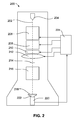
- Figure 2 depicts schematically a STEM equipped to perform the method according to the invention.
- a particle source in the form of an electron source 204 emits a beam of electrons along an optical axis 202.
- the electron source 204 is imaged by condenser optics 206 and passes through a corrector 208, said corrector correcting the aberrations of objective lens 212.
- a deflector unit 210 is placed, with which the beam can be scanned over the sample.
- the objective lens 212 focuses the beam onto the sample position 214, on which sample position 214 a sample is positioned.
- Electrons passing through the sample are imaged by projector optics 216 onto a fluorescent layer 218. In response to the electron bombardment this layer emits light, to be detected by camera 220 via fibre optics 222.
- the image detected by camera 220 is fed to a controller 224, which records and analyses the images coming from the camera and controls e.g. the condenser optics 206, the deflector unit 208, the corrector 210 and the objective lens 212.
- the controller 224 records a 1 st Ronchigram, Then a beam parameter is changed by e.g. changing the focal lenght of the objective lens 212, thus introducing a slight defocus ⁇ f, and a 2 nd Ronchigram is recorded. These two Ronchigrams are then compared, and for a large number of sites the positions of corresponding images of sample details (that is: the image positions of the same sample detail in the 1 st and in the 2 nd Ronchigram) are determined. From these position pairs and using one of formulae [4 a ], [4 b ] or [4 c ] (depending on the type of beam parameter changed) a set of equations result. By solving this set of equations the coefficients of the first derivative of the aberration function are determined, and the corrector 208 can be adjusted to reduce the aberrations present.
- a beam parameter is changed by e.g. changing the focal lenght of the objective lens 212, thus introducing a slight defocus ⁇ f, and
- Figure 3 shows schematically a representation of the shifts determined when comparing two Ronchigrams.
- Each of the vectors represents a shift in position of an image feature between the 1 st and the 2 nd Ronchigram, that is: the beginning of each vector represents the position of a certain sample feature in the 1 st Ronchigram and the end of each vector represents the position of said sample feature in the 2 nd Ronchigram.
Abstract
A lens of particle-optical apparatus, such as the objective lens, suffers from aberrations. As is already known since decades Ronchigrams can be used to determine these aberrations of particle-optical lenses.
Such methods rely e.g. on the determination of the 2nd derivative of the aberration function on the basis of local magnification in one or a set of Ronchigrams. Being dependent on the 2nd derivative the mathematics of these methods allow only (infinitesimal) small shifts between the Ronchigrams. However, this implies that e.g. the spatial quantization noise of the camera recording the Ronchigrams results in a large error. These conflicting requirements limit the accuracy and thus the usefulness of the known methods. The invention describes a set of algorithms which result in an improved method to quantify the lens aberration coefficients using a set of Ronchigrams.
Description
- The invention relates to a method for determining the aberration coefficients of the aberration function of a particle-optical lens, comprising:
- providing an amorphous sample with specimen details,
- providing a beam of particles,
- providing a lens for focusing said beam in the vicinity of the sample,
- detecting a 1st transmission Ronchigram showing an image of a plurality of sample details,
- changing a beam parameter by a known quantity,
- detecting a 2nd transmission Ronchigram showing an image of approximately the same sample details.
- The invention also relates to a particle-optical apparatus equipped to perform the method of the invention, and to software for automatically performing the method of the invention on such an apparatus.
- Such a method is known from the
US patent document No. 6,552,340 . - The method is used during the alignment of particle-optical elements of a particle-optical apparatus, such as a Scanning Transmission Electron Microscopes (STEM). More specifically this method is used for adjusting a corrector, said corrector correcting lens aberrations in such an apparatus.
- Particle-optical apparatus are used in e.g. the semiconductor industry for the inspection and analysis of samples taken from wafers. Another usage of such apparatus is in the field of biological research, where these apparatus are used for e.g. the analysis of pharmaceutical drugs and/or cell tissues.
- In a STEM an electron source produces a beam of electrons, which electrons are accelerated to an energy of e.g. 300 keV. One or more condenser lenses make an image of the electron source, which image is subsequently focussed on the sample to be analysed. Magnetic and/or electric deflection fields enable the scanning of the beam over the sample. Part of the electrons will pass through the sample, to be imaged by one or more projection lenses onto an image plane. This image plane can coincide with a fluorescent screen, or it can coincide with a CCD camera. Other detectors might be used to detect other information, such as the signal obtained from deflected or backscattered electrons, generated X-ray radiation, etc..
- Particle-optical apparatus often use particle-optical lenses that are magnetic or electrostatic monopole lenses (that is: the magnetic or electric field of these lenses show a rotational symmetry around the lens axis). Such lenses inevitably show spherical and chromatic aberrations. In modern apparatus the aberrations of the objective lens is corrected with a corrector. To adjust such a corrector properly it is necessary to determine the aberrations to be corrected.
- In the known method an electron beam is focussed on a transmission sample, and a 1st Ronchigram is formed on a CCD camera and recorded by that CCD camera. Then the beam is moved over the sample and a 2nd Ronchigram is recorded. Using these two Ronchigrams the local magnification on different positions in the Ronchigrams is determined, from which local magnification the 2nd derivative of the aberration function χ is derived.
The aberration function is known to the skilled person from e.g. "Upper limits for the residual aberrations of a high-resolution aberration-corrected STEM", M. Haider et al, Ultramicroscopy 81 (2000), page 168, formula (2). - The known method determines the second derivate by determining feature shifts caused by a change in beam position w.r.t. the sample. A correct value is only obtained for an infinitesimal small change in beam position. However, as a change in position must be observed, a large shift is preferred to eliminate e.g. the effects of sample drift occurring during the recording of a Ronchigram or occurring between the recording of different Ronchigrams, as well as problems relating to the limited spatial resolution of e.g. the CCD camera, resulting in spatial quantization noise. These conflicting requirements limit the accuracy and thus the usefulness of the known method.
- It is an object of the invention to provide a method with improved accuracy over the known method.
- To that end the method according to the invention is characterized in that
- the 1st derivative of the aberration function as a function of the position in the image plane of the lens is defined as a polynomial function with coefficients to be determined,
- for a plurality of sample details the position of the image of the sample details is determined in each of the Ronchigrams, giving a plurality of position pairs,
- with the use of these position pairs and with the use of an algorithm, said algorithm dependent on the type of beam parameter changed, the coefficients of the polynomial function are determined by solving a set of equations.
- The invention is based on the insight that with the use of a proper algorithm it is possible to determine the first derivative of the aberration function from two Ronchigrams of an amorphous sample. The invention is further based on the insight that the use of the first derivative of the aberration function allows a larger change of the beam position with respect to the sample than using the 2nd derivative, as used in the known method of
US 6,552,340 . As a consequence the resultant change in position of a sample feature between the Ronchigrams for the method according to the invention is also larger, thus resulting (at a given spatial resolution) in an image registration with a smaller relative error than with the known method and thus a more accurate determination of the aberration coefficients. - The image plane of the lens (perpendicular to the symmetry axis of the lens) can be described by an x- and y-axis with the origin at the symmetry axis of the lens (the z-axis coinciding with the lens axis). The aberration function in the image plane of the lens (which plane is perpendicular to the axis of the lens, herewith defined as the z-axis) is given by

Table 1: coefficients of the aberration function and corresponding lens aberrations Coefficient Name of corresponding lens aberration A0 Shift A1 Two-fold axial astigmatism or axial astigmatism of the 1st order C1 Defocus or spherical aberration of the 1st order A2 Three-fold axial astigmatism or axial astigmatism of the 2nd order B2 Axial coma A3 Four-fold axial astigmatism or axial astigmatism of the 3rd order C3 Spherical aberration of the 3rd order S3 Axial star aberration of the 3rd order A4 Five-fold axial astigmatism or axial astigmatism of the 4th order B4 Axial coma D4 Three lobe aberration of the 4th order A5 Six-fold axial astigmatism or axial astigmatism of the 5th order C5 Spherical aberration of the 5th order S5 Axial star aberration of the 5th order D5 Four lobe aberration of the 5th order - The coefficients of spherical aberration (C1, C3 and C5) are real numbers, while all other aberration coefficients are complex. The real and imaginary parts represent two independent contributions to the aberration. Consequently in equation [1] and table 1 there are actually 27 individual aberration coefficients present (25 when shift is not taken into account).
- It will now be shown how from a set of Ronchigrams the coefficients for the first derivative of the aberration function can be determined. A one dimensional description of the problem is given (showing only the effect of changes in the x-direction). However, the conclusions are valid for a two dimensional system (in x and y) as well. It is assumed that the first Ronchigram is made in a situation that the paraxial image plane coincides with the plane where the sample resides, although this is not necessary for the method according to the invention.
- A beam irradiating the sample can be thought to consist of a large number of rays. A certain sample feature present on the sample is imaged by a particular ray onto e.g. the CCD camera. For each Ronchigram and each sample feature a particular ray in the beam can be identified responsible for imaging said sample feature onto the camera plane. The magnification M between the camera plane and the aperture plane of the lens is given by M=L/f, with f the focal length of the lens and L the so-called camera length.
- The distance from such a ray to the optical axis is described by


- The second Ronchigram is recorded with a changed beam parameter.
- As a first example the beam is slightly defocused with a defocus ΔC1. The same feature is now imaged by another ray, whose distance from the axis is described by

- As a second example for the beam used to record the second Ronchigram, the beam is slightly shifted by a known beam shift S. The same feature is now imaged by another ray, whose distance from the axis is described by

- As a third example for the beam used to record the second Ronchigram, the beam is slightly tilted by a known beam tilt τ. The same feature is now imaged by another ray, whose distance from the axis is described by

- From the above formulae [3] it can be derived that the relation between the initial position in the first Ronchigram xa and the final position in the second Ronchigram xb can be written as:
- in the case of a defocus ΔC1

- in the case of a beam shift S

- and in the case of a beam tilt τ

- As mentioned earlier, according to the invention the derivative


- It is remarked that the effect of drift, which results in a uniform shift of the 2nd Ronchigram relative to the 1st Ronchigram, can be eliminated, as it is not position dependent. Drift is then an extra parameter which can be determined as an extra coefficient in the set of coefficients to be determined.
- It is further remarked that it is not necessary that the number of equations to be solved corresponds exactly with the number of coefficients. When a larger number of equations (a larger number of sets) are used, parameter fitting can be performed resulting in improved accuracy.
- It is remarked that in
US 6,858,844 another method is described to determine the beam profile by recording a so-called 'through-focus series' of scanned images, that is a series of images using different defocus values of the beam. A deconvolution of the images thus obtained then gives the beam profiles at different defocus distances from the focal point. The differences of these profiles are then used to determine beam aberrations. - A disadvantage of this method is that many images must be acquired in STEM mode (so: by scanning the beam over the sample). As is well-known to a person skilled in the art of TEM and STEM microscopy, making such an image is more time consuming then making a Ronchigram. Another disadvantage is that the sample must be of a type suited for deconvolution, implying a sample with well defined features. Therefore the sample used for the method of
US 6,858,844 is often of a special type, and after having determined the aberration coefficients (and having adjusted the corrector to minimize the aberrations), the sample must be taken out of the apparatus and the sample to be analysed must be inserted. This is time consuming, while there is also the risk that the behaviour of the corrector is influenced by the exchange, e.g. because of temperature changes due to such an exchange, resulting in an incorrect adjustment. - In an embodiment of the method according to the invention the change in beam parameter involves a change in the angle of the beam relative to the sample.
This embodiment is described by formula 4c. - In another embodiment of the method according to the invention the change in beam parameter involves a change in the focal length of a lens.
This embodiment is described by formula 4a. - It is to be remarked that to obtain such a change in the beam position it is not necessary to change the focal length of the lens focussing the beam onto the sample. By changing the strength of another lens between source and said lens the beam is displaced as well. This might have the advantage that a larger change in the (magnetic) field of such a lens can be used, with as a consequence less interference by e.g. magnetic hysteresis.
- In yet another embodiment of the method according to the invention the change in beam parameter involves a shift of the beam relative to the sample.
This embodiment is described by formula 4b. - It is remarked that, although this change in position between the recording of the Ronchigrams is also disclosed in the method known from
US 6,552,340 , the method according to the invention determines the coefficients in a different way. Therefore the method according to the invention differs from the method known fromUS 6,552,340 as well. - In a further embodiment of the method according to the invention the change in position is caused by an electric or magnetic field.
Although the change in position can be caused mechanically, it is much easier to obtain such a change by changing magnetic or electric fields. This is especially so because the changes required are very minute and must be known with an accuracy corresponding to almost atomically dimensions. - In still another embodiment the change in beam parameter involves a change in beam energy.
- In a further embodiment of the method according to the invention all features recorded in the 2nd Ronchigram are spatially pre-adjusted by an expected shift value before the relative displacement of the specimen details is determined.
- In yet a further embodiment of the method according to the invention a corrector is adjusted based on the coefficients determined.
- It is remarked that the method according to the invention might be used in an iterative way until e.g. all aberrations are smaller than certain preset values.
- The invention will be elucidated on the basis of figures, where identical reference numerals indicate corresponding elements.
To this end: - figure 1 depicts schematically a lens with spherical aberration, imaging sample features on a screen,
- figure 2 depicts schematically a STEM equipped to perform the method according to the invention, and
- figure 3 depicts schematically a field of vectors, each vector indicating the displacement of a sample feature between 2 Ronchigrams.
- Figure 1 shows schematically a lens with spherical aberration, imaging sample features on a screen.
Alens 101 with anoptical axis 102 focuses a particle beam consisting ofmany rays 103 on the Gaussian focal point 104. The particles are projected on aprojection screen 105, where they are recorded, e.g. by recording the light emitted by thescreen 105 due to the particle bombardment.
Due to spherical aberration of thelens 101 therays 103 removed from theaxis 102 are refracted too much and these rays intersect theaxis 102 at a position between the Gaussian focal point 104 and thelens 101.
On a 1stsample plane 110 two sample features are depicted, a 1st feature 111 on the axis and a 2ndfeature 113 located at an off-axis position. The 1st feature, intercepting the central ray of the beam, will produce a shadow image on thescreen 105 at location 112, the 2ndfeature 113, interceptingray 115, will produce a shadow image atlocation 114. - The magnification of the sample features on the
screen 105 depends on the place where therays 103 intercepted by that feature pass the axis 104 and the distance from sample plane to thescreen 105. As the distance from the sample to the screen 105 (the so-called camera length) in reality is much larger than the distance from sample to lens, which in turn is much larger than the different positions where the rays intersect the optical axis, the distance from the sample plane to the screen can be assumed to be almost constant (typical values for the camera length are tens of centimetres while the focal length of the lens is typically several millimetres, while the distance from the sample position to the focal plane is typically chosen less than 100 µm). Therefore the magnification of features on the sample changes dramatically when part of the images features are located at or very close to the focal plane of the lens. - As the (central part of the) 1st feature coincides with the focal point, it is imaged with an infinite magnification. The 2nd feature, removed from the focal plane, is magnified much less.
- When the sample is now shifted to another
sample plane 120 located at adistance Δf 106 away from the lens, the 1st feature, now atposition 121, forms its shadow image at position 122, coincident with the position 112 formed previously on thescreen 105, although its magnification is changed.
The 2nd feature, now positioned atlocation 123, forms a shadow image at position 124, which is displaced w.r.t.position 114 formed previously on thescreen 105. Its magnification is changed much less than that of the 1st feature, as the change in distance where the interceptedrays - It is remarked that if the sample is placed between the Gaussian focal point 104 and the position where the outermost rays intersect the
optical axis 102, there will be a ring on thescreen 105 around theoptical axis 102 where the magnification of the sample is infinite. This causes the circular patterns often observed on Ronchigrams. As a consequence the magnification of the 1st feature, located inside this ring, will have an opposite sign from the magnification of the 2nd feature, located outside this ring. - It is also remarked that for the method according to the invention it is undesirable to have such a ring of infinite magnification on the screen. Such a ring makes it difficult to determine the shift of a feature between the different Ronchigrams. Therefore the Ronchigrams recorded while performing the method according to the invention are preferably made with the Gaussian focal plane between lens and sample plane(s), that is with a slight over-focus of the lens.
- Assuming that the change in
position 106 of the sample is known, the spherical aberration and other aberrations can be deduced from the relative movement and magnification of the images of the features. - Although the above example uses a defocus as the different beam position w.r.t. the sample, it will be obvious that similar results can be obtained when a beam tilt or a beam shift is applied.
- It is remarked that to improve the accuracy of the method it is possible to record further Ronchigrams and to determine the aberration coefficients based on a set of e.g. three Ronchigrams.
- Figure 2 depicts schematically a STEM equipped to perform the method according to the invention.
- In a STEM 200 a particle source in the form of an
electron source 204 emits a beam of electrons along anoptical axis 202. Theelectron source 204 is imaged bycondenser optics 206 and passes through acorrector 208, said corrector correcting the aberrations ofobjective lens 212. Before the objective lens 212 adeflector unit 210 is placed, with which the beam can be scanned over the sample. Theobjective lens 212 focuses the beam onto thesample position 214, on which sample position 214 a sample is positioned. Electrons passing through the sample are imaged byprojector optics 216 onto afluorescent layer 218. In response to the electron bombardment this layer emits light, to be detected bycamera 220 viafibre optics 222. The image detected bycamera 220 is fed to acontroller 224, which records and analyses the images coming from the camera and controls e.g. thecondenser optics 206, thedeflector unit 208, thecorrector 210 and theobjective lens 212. - According to the invention the
controller 224 records a 1st Ronchigram, Then a beam parameter is changed by e.g. changing the focal lenght of theobjective lens 212, thus introducing a slight defocus Δf, and a 2nd Ronchigram is recorded. These two Ronchigrams are then compared, and for a large number of sites the positions of corresponding images of sample details (that is: the image positions of the same sample detail in the 1st and in the 2nd Ronchigram) are determined. From these position pairs and using one of formulae [4a], [4b] or [4c] (depending on the type of beam parameter changed) a set of equations result. By solving this set of equations the coefficients of the first derivative of the aberration function are determined, and thecorrector 208 can be adjusted to reduce the aberrations present. - Figure 3 shows schematically a representation of the shifts determined when comparing two Ronchigrams. Each of the vectors represents a shift in position of an image feature between the 1st and the 2nd Ronchigram, that is: the beginning of each vector represents the position of a certain sample feature in the 1st Ronchigram and the end of each vector represents the position of said sample feature in the 2nd Ronchigram.
Claims (10)
- Method for determining the aberration coefficients of the aberration function of a particle-optical lens, comprising:• providing an amorphous sample (110) with sample details (111, 113),• providing a beam of particles (103),• providing a lens (101) for focusing said beam in the vicinity of the sample• recording a 1st transmission Ronchigram showing an image of a plurality of sample details (112, 114),• changing a beam parameter by a known quantity• recording a 2nd transmission Ronchigram showing an image of approximately the same sample details,characterized in that• the 1st derivative of the aberration function as a function of the position in the image plane of the lens is defined as a polynomial function with coefficients to be determined,• for a plurality of sample details the position of the image of the sample details is determined in each of the Ronchigrams, giving a plurality of position pairs,• with the use of these position pairs and with the use of an algorithm, said algorithm dependent on the type of beam parameter changed, the coefficients of the polynomial function are determined by solving a set of equations.
- Method according to Claim 1 in which the change in beam parameter involves a change in the angle of the beam relative to the sample.
- Method according to Claim 1 in which the change in beam parameter involves a change in the focal length of a lens.
- Method according to Claim 1 in which the change in beam parameter involves a shift of the beam relative to the sample.
- Method accord to any of the preceding Claims in which the change is caused by a change of an electrostatic or magnetic field.
- Method according to Claim 1 in which the change in beam parameter involves the change of the energy of the beam.
- Method according to any of the preceding Claims in which the position of all features recorded in the 2nd Ronchigram are spatially pre-adjusted by an expected shift value before the relative displacement of the specimen details is determined.
- Method according to any of the preceding Claims in which a corrector is adjusted based on the aberration coefficients determined.
- Particle-optical apparatus equipped to perform the method according to any of the preceding Claims.
- Software for automatically performing the method according to any of Claims 1-8 on the apparatus according to Claim 9.
Priority Applications (6)
| Application Number | Priority Date | Filing Date | Title |
|---|---|---|---|
| EP05111741A EP1796130A1 (en) | 2005-12-06 | 2005-12-06 | Method for determining the aberration coefficients of the aberration function of a particle-optical lens. |
| US11/634,283 US7544939B2 (en) | 2005-12-06 | 2006-12-05 | Method for determining the aberration coefficients of the aberration function of a particle-optical lens |
| DE602006007533T DE602006007533D1 (en) | 2005-12-06 | 2006-12-05 | Method for determining the aberration coefficients of the aberration function of a particle-optical lens |
| JP2006327873A JP4553889B2 (en) | 2005-12-06 | 2006-12-05 | Determination method of aberration coefficient in aberration function of particle optical lens |
| EP06125369A EP1804272B1 (en) | 2005-12-06 | 2006-12-05 | Method for determining the aberration coefficients of the aberration function of a particle-opticle lens. |
| CN2006101688584A CN1979751B (en) | 2005-12-06 | 2006-12-06 | Method for determining the aberration coefficients of the aberration function of a particle-optical lens |
Applications Claiming Priority (1)
| Application Number | Priority Date | Filing Date | Title |
|---|---|---|---|
| EP05111741A EP1796130A1 (en) | 2005-12-06 | 2005-12-06 | Method for determining the aberration coefficients of the aberration function of a particle-optical lens. |
Publications (1)
| Publication Number | Publication Date |
|---|---|
| EP1796130A1 true EP1796130A1 (en) | 2007-06-13 |
Family
ID=36217948
Family Applications (2)
| Application Number | Title | Priority Date | Filing Date |
|---|---|---|---|
| EP05111741A Withdrawn EP1796130A1 (en) | 2005-12-06 | 2005-12-06 | Method for determining the aberration coefficients of the aberration function of a particle-optical lens. |
| EP06125369A Expired - Fee Related EP1804272B1 (en) | 2005-12-06 | 2006-12-05 | Method for determining the aberration coefficients of the aberration function of a particle-opticle lens. |
Family Applications After (1)
| Application Number | Title | Priority Date | Filing Date |
|---|---|---|---|
| EP06125369A Expired - Fee Related EP1804272B1 (en) | 2005-12-06 | 2006-12-05 | Method for determining the aberration coefficients of the aberration function of a particle-opticle lens. |
Country Status (5)
| Country | Link |
|---|---|
| US (1) | US7544939B2 (en) |
| EP (2) | EP1796130A1 (en) |
| JP (1) | JP4553889B2 (en) |
| CN (1) | CN1979751B (en) |
| DE (1) | DE602006007533D1 (en) |
Cited By (2)
| Publication number | Priority date | Publication date | Assignee | Title |
|---|---|---|---|---|
| EP2568284A3 (en) * | 2011-09-09 | 2013-03-20 | Sumitomo Rubber Industries, Ltd. | Method for simulating deformation of rubber compound with filler particles |
| EP2570808A3 (en) * | 2011-09-14 | 2013-03-27 | Sumitomo Rubber Industries, Ltd. | Method for simulating deformation of rubber compound |
Families Citing this family (17)
| Publication number | Priority date | Publication date | Assignee | Title |
|---|---|---|---|---|
| EP1783811A3 (en) * | 2005-11-02 | 2008-02-27 | FEI Company | Corrector for the correction of chromatic aberrations in a particle-optical apparatus |
| JP5078431B2 (en) * | 2007-05-17 | 2012-11-21 | 株式会社日立ハイテクノロジーズ | Charged particle beam device, aberration correction value calculation device thereof, and aberration correction program thereof |
| EP2197018A1 (en) * | 2008-12-12 | 2010-06-16 | FEI Company | Method for determining distortions in a particle-optical apparatus |
| JP5331893B2 (en) * | 2009-10-26 | 2013-10-30 | 株式会社日立ハイテクノロジーズ | Scanning charged particle beam apparatus and chromatic spherical aberration correction method |
| EP2325862A1 (en) * | 2009-11-18 | 2011-05-25 | Fei Company | Corrector for axial aberrations of a particle-optical lens |
| US20110142362A1 (en) * | 2009-12-11 | 2011-06-16 | Marimon Sanjuan David | Method for filtering data with symmetric weighted integral images |
| EP2600382A1 (en) * | 2010-07-27 | 2013-06-05 | Hitachi High-Technologies Corporation | Aberration correction device and charged particle beam device employing same |
| JP5423612B2 (en) * | 2010-08-16 | 2014-02-19 | 富士通株式会社 | Confocal scanning transmission electron microscope apparatus and three-dimensional tomographic image observation method |
| EP2511936B1 (en) | 2011-04-13 | 2013-10-02 | Fei Company | Distortion free stigmation of a TEM |
| EP2584584A1 (en) | 2011-10-19 | 2013-04-24 | FEI Company | Method for adjusting a STEM equipped with an aberration corrector |
| EP2704177B1 (en) | 2012-09-04 | 2014-11-26 | Fei Company | Method of investigating and correcting aberrations in a charged-particle lens system |
| JP6163063B2 (en) * | 2013-09-13 | 2017-07-12 | 株式会社日立ハイテクノロジーズ | Scanning transmission electron microscope and aberration measurement method thereof |
| US10157727B2 (en) | 2017-03-02 | 2018-12-18 | Fei Company | Aberration measurement in a charged particle microscope |
| US20200311886A1 (en) * | 2019-03-28 | 2020-10-01 | Carl Zeiss Microscopy Gmbh | Method for determining an image recording aberration |
| DE102019120279B3 (en) * | 2019-07-26 | 2020-09-24 | Carl Zeiss Microscopy Gmbh | Method for operating a particle beam microscope and a particle beam microscope |
| JP6962979B2 (en) * | 2019-09-12 | 2021-11-05 | 日本電子株式会社 | How to get a darkfield image |
| JP7250055B2 (en) * | 2021-02-16 | 2023-03-31 | 日本電子株式会社 | Estimation model creation method and electron microscope |
Citations (2)
| Publication number | Priority date | Publication date | Assignee | Title |
|---|---|---|---|---|
| US5581347A (en) * | 1993-09-17 | 1996-12-03 | Essilor International | Optimization method and device for direct measurement of an optical component |
| EP1197986A2 (en) * | 2000-10-12 | 2002-04-17 | Nion Co. | Autoadjusting charged-particle probe-forming apparatus |
Family Cites Families (3)
| Publication number | Priority date | Publication date | Assignee | Title |
|---|---|---|---|---|
| DE10003127A1 (en) | 2000-01-26 | 2001-08-02 | Ceos Gmbh | Method for determining geometrically optical aberrations |
| CN1255850C (en) * | 2003-07-24 | 2006-05-10 | 上海市计量测试技术研究院 | Correcting method for astigmatism of scanning electronic microscope |
| JP4790567B2 (en) * | 2005-11-30 | 2011-10-12 | 日本電子株式会社 | Aberration measurement method, aberration correction method and electron microscope using Ronchigram |
-
2005
- 2005-12-06 EP EP05111741A patent/EP1796130A1/en not_active Withdrawn
-
2006
- 2006-12-05 JP JP2006327873A patent/JP4553889B2/en not_active Expired - Fee Related
- 2006-12-05 US US11/634,283 patent/US7544939B2/en active Active
- 2006-12-05 DE DE602006007533T patent/DE602006007533D1/en active Active
- 2006-12-05 EP EP06125369A patent/EP1804272B1/en not_active Expired - Fee Related
- 2006-12-06 CN CN2006101688584A patent/CN1979751B/en not_active Expired - Fee Related
Patent Citations (2)
| Publication number | Priority date | Publication date | Assignee | Title |
|---|---|---|---|---|
| US5581347A (en) * | 1993-09-17 | 1996-12-03 | Essilor International | Optimization method and device for direct measurement of an optical component |
| EP1197986A2 (en) * | 2000-10-12 | 2002-04-17 | Nion Co. | Autoadjusting charged-particle probe-forming apparatus |
Cited By (4)
| Publication number | Priority date | Publication date | Assignee | Title |
|---|---|---|---|---|
| EP2568284A3 (en) * | 2011-09-09 | 2013-03-20 | Sumitomo Rubber Industries, Ltd. | Method for simulating deformation of rubber compound with filler particles |
| EP2570808A3 (en) * | 2011-09-14 | 2013-03-27 | Sumitomo Rubber Industries, Ltd. | Method for simulating deformation of rubber compound |
| CN103164563A (en) * | 2011-09-14 | 2013-06-19 | 住友橡胶工业株式会社 | Method for simulating deformation of rubber compound |
| US9097697B2 (en) | 2011-09-14 | 2015-08-04 | Sumitomo Rubber Industries, Ltd. | Method for simulating deformation of rubber compound |
Also Published As
| Publication number | Publication date |
|---|---|
| DE602006007533D1 (en) | 2009-08-13 |
| JP2007157719A (en) | 2007-06-21 |
| JP4553889B2 (en) | 2010-09-29 |
| US20070125945A1 (en) | 2007-06-07 |
| EP1804272A2 (en) | 2007-07-04 |
| EP1804272B1 (en) | 2009-07-01 |
| CN1979751A (en) | 2007-06-13 |
| CN1979751B (en) | 2011-01-26 |
| EP1804272A3 (en) | 2007-07-11 |
| US7544939B2 (en) | 2009-06-09 |
Similar Documents
| Publication | Publication Date | Title |
|---|---|---|
| EP1804272B1 (en) | Method for determining the aberration coefficients of the aberration function of a particle-opticle lens. | |
| US8692196B2 (en) | Method of use for a multipole detector for a transmission electron microscope | |
| JP6278553B2 (en) | Secondary electron optical system and detection device | |
| EP2639814B1 (en) | Charged particle optical equipment and method for measuring lens aberration | |
| JP5603421B2 (en) | Charged particle beam equipment with automatic aberration correction method | |
| US9136087B2 (en) | Method of investigating and correcting aberrations in a charged-particle lens system | |
| JP2005310602A (en) | Charged particle beam adjustment method and charged particle beam device | |
| WO2015015985A1 (en) | Charged particle beam device and aberration measurement method in charged particle beam device | |
| US11817290B2 (en) | Method, device and system for reducing off-axial aberration in electron microscopy | |
| JP2006173027A (en) | Scanning transmission electron microscope, aberration measuring method, and aberration correction method | |
| US10446362B2 (en) | Distortion correction method and electron microscope | |
| EP1883094B1 (en) | Charged particle beam device and method for inspecting specimen | |
| EP2600379A1 (en) | Scanning transmission electron microscope and axial adjustment method thereof | |
| JP2000311645A (en) | Electron microscope | |
| WO2015037313A1 (en) | Scanning transmission electron microscope and aberration measurement method therefor | |
| JP4431624B2 (en) | Charged particle beam adjustment method and charged particle beam apparatus | |
| JP7285871B2 (en) | Scanning Transmission Electron Microscope and Optical System Adjustment Method | |
| EP3905302A1 (en) | Scanning transmission electron microscope and adjustment method of optical system | |
| JP2010016007A (en) | Charged particle beam adjustment method, and charged particle beam device |
Legal Events
| Date | Code | Title | Description |
|---|---|---|---|
| PUAI | Public reference made under article 153(3) epc to a published international application that has entered the european phase |
Free format text: ORIGINAL CODE: 0009012 |
|
| AK | Designated contracting states |
Kind code of ref document: A1 Designated state(s): AT BE BG CH CY CZ DE DK EE ES FI FR GB GR HU IE IS IT LI LT LU LV MC NL PL PT RO SE SI SK TR |
|
| AX | Request for extension of the european patent |
Extension state: AL BA HR MK YU |
|
| AKX | Designation fees paid | ||
| REG | Reference to a national code |
Ref country code: DE Ref legal event code: 8566 |
|
| STAA | Information on the status of an ep patent application or granted ep patent |
Free format text: STATUS: THE APPLICATION IS DEEMED TO BE WITHDRAWN |
|
| 18D | Application deemed to be withdrawn |
Effective date: 20071214 |