EP1799145B1 - Gastrointestinal anchor - Google Patents
Gastrointestinal anchor Download PDFInfo
- Publication number
- EP1799145B1 EP1799145B1 EP05797460.2A EP05797460A EP1799145B1 EP 1799145 B1 EP1799145 B1 EP 1799145B1 EP 05797460 A EP05797460 A EP 05797460A EP 1799145 B1 EP1799145 B1 EP 1799145B1
- Authority
- EP
- European Patent Office
- Prior art keywords
- anchor
- anchoring
- intraluminal
- tube
- elongated
- Prior art date
- Legal status (The legal status is an assumption and is not a legal conclusion. Google has not performed a legal analysis and makes no representation as to the accuracy of the status listed.)
- Not-in-force
Links
Images


Classifications
-
- A—HUMAN NECESSITIES
- A61—MEDICAL OR VETERINARY SCIENCE; HYGIENE
- A61F—FILTERS IMPLANTABLE INTO BLOOD VESSELS; PROSTHESES; DEVICES PROVIDING PATENCY TO, OR PREVENTING COLLAPSING OF, TUBULAR STRUCTURES OF THE BODY, e.g. STENTS; ORTHOPAEDIC, NURSING OR CONTRACEPTIVE DEVICES; FOMENTATION; TREATMENT OR PROTECTION OF EYES OR EARS; BANDAGES, DRESSINGS OR ABSORBENT PADS; FIRST-AID KITS
- A61F5/00—Orthopaedic methods or devices for non-surgical treatment of bones or joints; Nursing devices; Anti-rape devices
- A61F5/0003—Apparatus for the treatment of obesity; Anti-eating devices
- A61F5/0013—Implantable devices or invasive measures
- A61F5/0076—Implantable devices or invasive measures preventing normal digestion, e.g. Bariatric or gastric sleeves
-
- A—HUMAN NECESSITIES
- A61—MEDICAL OR VETERINARY SCIENCE; HYGIENE
- A61F—FILTERS IMPLANTABLE INTO BLOOD VESSELS; PROSTHESES; DEVICES PROVIDING PATENCY TO, OR PREVENTING COLLAPSING OF, TUBULAR STRUCTURES OF THE BODY, e.g. STENTS; ORTHOPAEDIC, NURSING OR CONTRACEPTIVE DEVICES; FOMENTATION; TREATMENT OR PROTECTION OF EYES OR EARS; BANDAGES, DRESSINGS OR ABSORBENT PADS; FIRST-AID KITS
- A61F2/00—Filters implantable into blood vessels; Prostheses, i.e. artificial substitutes or replacements for parts of the body; Appliances for connecting them with the body; Devices providing patency to, or preventing collapsing of, tubular structures of the body, e.g. stents
- A61F2/02—Prostheses implantable into the body
- A61F2/04—Hollow or tubular parts of organs, e.g. bladders, tracheae, bronchi or bile ducts
- A61F2/06—Blood vessels
- A61F2/07—Stent-grafts
-
- A—HUMAN NECESSITIES
- A61—MEDICAL OR VETERINARY SCIENCE; HYGIENE
- A61F—FILTERS IMPLANTABLE INTO BLOOD VESSELS; PROSTHESES; DEVICES PROVIDING PATENCY TO, OR PREVENTING COLLAPSING OF, TUBULAR STRUCTURES OF THE BODY, e.g. STENTS; ORTHOPAEDIC, NURSING OR CONTRACEPTIVE DEVICES; FOMENTATION; TREATMENT OR PROTECTION OF EYES OR EARS; BANDAGES, DRESSINGS OR ABSORBENT PADS; FIRST-AID KITS
- A61F2/00—Filters implantable into blood vessels; Prostheses, i.e. artificial substitutes or replacements for parts of the body; Appliances for connecting them with the body; Devices providing patency to, or preventing collapsing of, tubular structures of the body, e.g. stents
- A61F2/82—Devices providing patency to, or preventing collapsing of, tubular structures of the body, e.g. stents
- A61F2/86—Stents in a form characterised by the wire-like elements; Stents in the form characterised by a net-like or mesh-like structure
-
- A—HUMAN NECESSITIES
- A61—MEDICAL OR VETERINARY SCIENCE; HYGIENE
- A61F—FILTERS IMPLANTABLE INTO BLOOD VESSELS; PROSTHESES; DEVICES PROVIDING PATENCY TO, OR PREVENTING COLLAPSING OF, TUBULAR STRUCTURES OF THE BODY, e.g. STENTS; ORTHOPAEDIC, NURSING OR CONTRACEPTIVE DEVICES; FOMENTATION; TREATMENT OR PROTECTION OF EYES OR EARS; BANDAGES, DRESSINGS OR ABSORBENT PADS; FIRST-AID KITS
- A61F2/00—Filters implantable into blood vessels; Prostheses, i.e. artificial substitutes or replacements for parts of the body; Appliances for connecting them with the body; Devices providing patency to, or preventing collapsing of, tubular structures of the body, e.g. stents
- A61F2/02—Prostheses implantable into the body
- A61F2/04—Hollow or tubular parts of organs, e.g. bladders, tracheae, bronchi or bile ducts
- A61F2/06—Blood vessels
-
- A—HUMAN NECESSITIES
- A61—MEDICAL OR VETERINARY SCIENCE; HYGIENE
- A61F—FILTERS IMPLANTABLE INTO BLOOD VESSELS; PROSTHESES; DEVICES PROVIDING PATENCY TO, OR PREVENTING COLLAPSING OF, TUBULAR STRUCTURES OF THE BODY, e.g. STENTS; ORTHOPAEDIC, NURSING OR CONTRACEPTIVE DEVICES; FOMENTATION; TREATMENT OR PROTECTION OF EYES OR EARS; BANDAGES, DRESSINGS OR ABSORBENT PADS; FIRST-AID KITS
- A61F2/00—Filters implantable into blood vessels; Prostheses, i.e. artificial substitutes or replacements for parts of the body; Appliances for connecting them with the body; Devices providing patency to, or preventing collapsing of, tubular structures of the body, e.g. stents
- A61F2/82—Devices providing patency to, or preventing collapsing of, tubular structures of the body, e.g. stents
- A61F2/86—Stents in a form characterised by the wire-like elements; Stents in the form characterised by a net-like or mesh-like structure
- A61F2/89—Stents in a form characterised by the wire-like elements; Stents in the form characterised by a net-like or mesh-like structure the wire-like elements comprising two or more adjacent rings flexibly connected by separate members
-
- A—HUMAN NECESSITIES
- A61—MEDICAL OR VETERINARY SCIENCE; HYGIENE
- A61F—FILTERS IMPLANTABLE INTO BLOOD VESSELS; PROSTHESES; DEVICES PROVIDING PATENCY TO, OR PREVENTING COLLAPSING OF, TUBULAR STRUCTURES OF THE BODY, e.g. STENTS; ORTHOPAEDIC, NURSING OR CONTRACEPTIVE DEVICES; FOMENTATION; TREATMENT OR PROTECTION OF EYES OR EARS; BANDAGES, DRESSINGS OR ABSORBENT PADS; FIRST-AID KITS
- A61F2/00—Filters implantable into blood vessels; Prostheses, i.e. artificial substitutes or replacements for parts of the body; Appliances for connecting them with the body; Devices providing patency to, or preventing collapsing of, tubular structures of the body, e.g. stents
- A61F2/82—Devices providing patency to, or preventing collapsing of, tubular structures of the body, e.g. stents
- A61F2/86—Stents in a form characterised by the wire-like elements; Stents in the form characterised by a net-like or mesh-like structure
- A61F2/90—Stents in a form characterised by the wire-like elements; Stents in the form characterised by a net-like or mesh-like structure characterised by a net-like or mesh-like structure
- A61F2/91—Stents in a form characterised by the wire-like elements; Stents in the form characterised by a net-like or mesh-like structure characterised by a net-like or mesh-like structure made from perforated sheet material or tubes, e.g. perforated by laser cuts or etched holes
- A61F2/915—Stents in a form characterised by the wire-like elements; Stents in the form characterised by a net-like or mesh-like structure characterised by a net-like or mesh-like structure made from perforated sheet material or tubes, e.g. perforated by laser cuts or etched holes with bands having a meander structure, adjacent bands being connected to each other
-
- A—HUMAN NECESSITIES
- A61—MEDICAL OR VETERINARY SCIENCE; HYGIENE
- A61F—FILTERS IMPLANTABLE INTO BLOOD VESSELS; PROSTHESES; DEVICES PROVIDING PATENCY TO, OR PREVENTING COLLAPSING OF, TUBULAR STRUCTURES OF THE BODY, e.g. STENTS; ORTHOPAEDIC, NURSING OR CONTRACEPTIVE DEVICES; FOMENTATION; TREATMENT OR PROTECTION OF EYES OR EARS; BANDAGES, DRESSINGS OR ABSORBENT PADS; FIRST-AID KITS
- A61F2/00—Filters implantable into blood vessels; Prostheses, i.e. artificial substitutes or replacements for parts of the body; Appliances for connecting them with the body; Devices providing patency to, or preventing collapsing of, tubular structures of the body, e.g. stents
- A61F2/02—Prostheses implantable into the body
- A61F2/04—Hollow or tubular parts of organs, e.g. bladders, tracheae, bronchi or bile ducts
- A61F2002/045—Stomach, intestines
-
- A—HUMAN NECESSITIES
- A61—MEDICAL OR VETERINARY SCIENCE; HYGIENE
- A61F—FILTERS IMPLANTABLE INTO BLOOD VESSELS; PROSTHESES; DEVICES PROVIDING PATENCY TO, OR PREVENTING COLLAPSING OF, TUBULAR STRUCTURES OF THE BODY, e.g. STENTS; ORTHOPAEDIC, NURSING OR CONTRACEPTIVE DEVICES; FOMENTATION; TREATMENT OR PROTECTION OF EYES OR EARS; BANDAGES, DRESSINGS OR ABSORBENT PADS; FIRST-AID KITS
- A61F2/00—Filters implantable into blood vessels; Prostheses, i.e. artificial substitutes or replacements for parts of the body; Appliances for connecting them with the body; Devices providing patency to, or preventing collapsing of, tubular structures of the body, e.g. stents
- A61F2/02—Prostheses implantable into the body
- A61F2/04—Hollow or tubular parts of organs, e.g. bladders, tracheae, bronchi or bile ducts
- A61F2/06—Blood vessels
- A61F2/07—Stent-grafts
- A61F2002/072—Encapsulated stents, e.g. wire or whole stent embedded in lining
-
- A—HUMAN NECESSITIES
- A61—MEDICAL OR VETERINARY SCIENCE; HYGIENE
- A61F—FILTERS IMPLANTABLE INTO BLOOD VESSELS; PROSTHESES; DEVICES PROVIDING PATENCY TO, OR PREVENTING COLLAPSING OF, TUBULAR STRUCTURES OF THE BODY, e.g. STENTS; ORTHOPAEDIC, NURSING OR CONTRACEPTIVE DEVICES; FOMENTATION; TREATMENT OR PROTECTION OF EYES OR EARS; BANDAGES, DRESSINGS OR ABSORBENT PADS; FIRST-AID KITS
- A61F2/00—Filters implantable into blood vessels; Prostheses, i.e. artificial substitutes or replacements for parts of the body; Appliances for connecting them with the body; Devices providing patency to, or preventing collapsing of, tubular structures of the body, e.g. stents
- A61F2/02—Prostheses implantable into the body
- A61F2/04—Hollow or tubular parts of organs, e.g. bladders, tracheae, bronchi or bile ducts
- A61F2/06—Blood vessels
- A61F2/07—Stent-grafts
- A61F2002/075—Stent-grafts the stent being loosely attached to the graft material, e.g. by stitching
-
- A—HUMAN NECESSITIES
- A61—MEDICAL OR VETERINARY SCIENCE; HYGIENE
- A61F—FILTERS IMPLANTABLE INTO BLOOD VESSELS; PROSTHESES; DEVICES PROVIDING PATENCY TO, OR PREVENTING COLLAPSING OF, TUBULAR STRUCTURES OF THE BODY, e.g. STENTS; ORTHOPAEDIC, NURSING OR CONTRACEPTIVE DEVICES; FOMENTATION; TREATMENT OR PROTECTION OF EYES OR EARS; BANDAGES, DRESSINGS OR ABSORBENT PADS; FIRST-AID KITS
- A61F2/00—Filters implantable into blood vessels; Prostheses, i.e. artificial substitutes or replacements for parts of the body; Appliances for connecting them with the body; Devices providing patency to, or preventing collapsing of, tubular structures of the body, e.g. stents
- A61F2/82—Devices providing patency to, or preventing collapsing of, tubular structures of the body, e.g. stents
- A61F2002/828—Means for connecting a plurality of stents allowing flexibility of the whole structure
-
- A—HUMAN NECESSITIES
- A61—MEDICAL OR VETERINARY SCIENCE; HYGIENE
- A61F—FILTERS IMPLANTABLE INTO BLOOD VESSELS; PROSTHESES; DEVICES PROVIDING PATENCY TO, OR PREVENTING COLLAPSING OF, TUBULAR STRUCTURES OF THE BODY, e.g. STENTS; ORTHOPAEDIC, NURSING OR CONTRACEPTIVE DEVICES; FOMENTATION; TREATMENT OR PROTECTION OF EYES OR EARS; BANDAGES, DRESSINGS OR ABSORBENT PADS; FIRST-AID KITS
- A61F2/00—Filters implantable into blood vessels; Prostheses, i.e. artificial substitutes or replacements for parts of the body; Appliances for connecting them with the body; Devices providing patency to, or preventing collapsing of, tubular structures of the body, e.g. stents
- A61F2/82—Devices providing patency to, or preventing collapsing of, tubular structures of the body, e.g. stents
- A61F2/848—Devices providing patency to, or preventing collapsing of, tubular structures of the body, e.g. stents having means for fixation to the vessel wall, e.g. barbs
- A61F2002/8483—Barbs
-
- A—HUMAN NECESSITIES
- A61—MEDICAL OR VETERINARY SCIENCE; HYGIENE
- A61F—FILTERS IMPLANTABLE INTO BLOOD VESSELS; PROSTHESES; DEVICES PROVIDING PATENCY TO, OR PREVENTING COLLAPSING OF, TUBULAR STRUCTURES OF THE BODY, e.g. STENTS; ORTHOPAEDIC, NURSING OR CONTRACEPTIVE DEVICES; FOMENTATION; TREATMENT OR PROTECTION OF EYES OR EARS; BANDAGES, DRESSINGS OR ABSORBENT PADS; FIRST-AID KITS
- A61F2/00—Filters implantable into blood vessels; Prostheses, i.e. artificial substitutes or replacements for parts of the body; Appliances for connecting them with the body; Devices providing patency to, or preventing collapsing of, tubular structures of the body, e.g. stents
- A61F2/95—Instruments specially adapted for placement or removal of stents or stent-grafts
- A61F2002/9534—Instruments specially adapted for placement or removal of stents or stent-grafts for repositioning of stents
-
- A—HUMAN NECESSITIES
- A61—MEDICAL OR VETERINARY SCIENCE; HYGIENE
- A61F—FILTERS IMPLANTABLE INTO BLOOD VESSELS; PROSTHESES; DEVICES PROVIDING PATENCY TO, OR PREVENTING COLLAPSING OF, TUBULAR STRUCTURES OF THE BODY, e.g. STENTS; ORTHOPAEDIC, NURSING OR CONTRACEPTIVE DEVICES; FOMENTATION; TREATMENT OR PROTECTION OF EYES OR EARS; BANDAGES, DRESSINGS OR ABSORBENT PADS; FIRST-AID KITS
- A61F2210/00—Particular material properties of prostheses classified in groups A61F2/00 - A61F2/26 or A61F2/82 or A61F9/00 or A61F11/00 or subgroups thereof
- A61F2210/0076—Particular material properties of prostheses classified in groups A61F2/00 - A61F2/26 or A61F2/82 or A61F9/00 or A61F11/00 or subgroups thereof multilayered, e.g. laminated structures
-
- A—HUMAN NECESSITIES
- A61—MEDICAL OR VETERINARY SCIENCE; HYGIENE
- A61F—FILTERS IMPLANTABLE INTO BLOOD VESSELS; PROSTHESES; DEVICES PROVIDING PATENCY TO, OR PREVENTING COLLAPSING OF, TUBULAR STRUCTURES OF THE BODY, e.g. STENTS; ORTHOPAEDIC, NURSING OR CONTRACEPTIVE DEVICES; FOMENTATION; TREATMENT OR PROTECTION OF EYES OR EARS; BANDAGES, DRESSINGS OR ABSORBENT PADS; FIRST-AID KITS
- A61F2220/00—Fixations or connections for prostheses classified in groups A61F2/00 - A61F2/26 or A61F2/82 or A61F9/00 or A61F11/00 or subgroups thereof
- A61F2220/0008—Fixation appliances for connecting prostheses to the body
- A61F2220/0016—Fixation appliances for connecting prostheses to the body with sharp anchoring protrusions, e.g. barbs, pins, spikes
-
- A—HUMAN NECESSITIES
- A61—MEDICAL OR VETERINARY SCIENCE; HYGIENE
- A61F—FILTERS IMPLANTABLE INTO BLOOD VESSELS; PROSTHESES; DEVICES PROVIDING PATENCY TO, OR PREVENTING COLLAPSING OF, TUBULAR STRUCTURES OF THE BODY, e.g. STENTS; ORTHOPAEDIC, NURSING OR CONTRACEPTIVE DEVICES; FOMENTATION; TREATMENT OR PROTECTION OF EYES OR EARS; BANDAGES, DRESSINGS OR ABSORBENT PADS; FIRST-AID KITS
- A61F2220/00—Fixations or connections for prostheses classified in groups A61F2/00 - A61F2/26 or A61F2/82 or A61F9/00 or A61F11/00 or subgroups thereof
- A61F2220/0025—Connections or couplings between prosthetic parts, e.g. between modular parts; Connecting elements
- A61F2220/005—Connections or couplings between prosthetic parts, e.g. between modular parts; Connecting elements using adhesives
-
- A—HUMAN NECESSITIES
- A61—MEDICAL OR VETERINARY SCIENCE; HYGIENE
- A61F—FILTERS IMPLANTABLE INTO BLOOD VESSELS; PROSTHESES; DEVICES PROVIDING PATENCY TO, OR PREVENTING COLLAPSING OF, TUBULAR STRUCTURES OF THE BODY, e.g. STENTS; ORTHOPAEDIC, NURSING OR CONTRACEPTIVE DEVICES; FOMENTATION; TREATMENT OR PROTECTION OF EYES OR EARS; BANDAGES, DRESSINGS OR ABSORBENT PADS; FIRST-AID KITS
- A61F2220/00—Fixations or connections for prostheses classified in groups A61F2/00 - A61F2/26 or A61F2/82 or A61F9/00 or A61F11/00 or subgroups thereof
- A61F2220/0025—Connections or couplings between prosthetic parts, e.g. between modular parts; Connecting elements
- A61F2220/0058—Connections or couplings between prosthetic parts, e.g. between modular parts; Connecting elements soldered or brazed or welded
-
- A—HUMAN NECESSITIES
- A61—MEDICAL OR VETERINARY SCIENCE; HYGIENE
- A61F—FILTERS IMPLANTABLE INTO BLOOD VESSELS; PROSTHESES; DEVICES PROVIDING PATENCY TO, OR PREVENTING COLLAPSING OF, TUBULAR STRUCTURES OF THE BODY, e.g. STENTS; ORTHOPAEDIC, NURSING OR CONTRACEPTIVE DEVICES; FOMENTATION; TREATMENT OR PROTECTION OF EYES OR EARS; BANDAGES, DRESSINGS OR ABSORBENT PADS; FIRST-AID KITS
- A61F2220/00—Fixations or connections for prostheses classified in groups A61F2/00 - A61F2/26 or A61F2/82 or A61F9/00 or A61F11/00 or subgroups thereof
- A61F2220/0025—Connections or couplings between prosthetic parts, e.g. between modular parts; Connecting elements
- A61F2220/0066—Connections or couplings between prosthetic parts, e.g. between modular parts; Connecting elements stapled
-
- A—HUMAN NECESSITIES
- A61—MEDICAL OR VETERINARY SCIENCE; HYGIENE
- A61F—FILTERS IMPLANTABLE INTO BLOOD VESSELS; PROSTHESES; DEVICES PROVIDING PATENCY TO, OR PREVENTING COLLAPSING OF, TUBULAR STRUCTURES OF THE BODY, e.g. STENTS; ORTHOPAEDIC, NURSING OR CONTRACEPTIVE DEVICES; FOMENTATION; TREATMENT OR PROTECTION OF EYES OR EARS; BANDAGES, DRESSINGS OR ABSORBENT PADS; FIRST-AID KITS
- A61F2220/00—Fixations or connections for prostheses classified in groups A61F2/00 - A61F2/26 or A61F2/82 or A61F9/00 or A61F11/00 or subgroups thereof
- A61F2220/0025—Connections or couplings between prosthetic parts, e.g. between modular parts; Connecting elements
- A61F2220/0075—Connections or couplings between prosthetic parts, e.g. between modular parts; Connecting elements sutured, ligatured or stitched, retained or tied with a rope, string, thread, wire or cable
-
- A—HUMAN NECESSITIES
- A61—MEDICAL OR VETERINARY SCIENCE; HYGIENE
- A61F—FILTERS IMPLANTABLE INTO BLOOD VESSELS; PROSTHESES; DEVICES PROVIDING PATENCY TO, OR PREVENTING COLLAPSING OF, TUBULAR STRUCTURES OF THE BODY, e.g. STENTS; ORTHOPAEDIC, NURSING OR CONTRACEPTIVE DEVICES; FOMENTATION; TREATMENT OR PROTECTION OF EYES OR EARS; BANDAGES, DRESSINGS OR ABSORBENT PADS; FIRST-AID KITS
- A61F2250/00—Special features of prostheses classified in groups A61F2/00 - A61F2/26 or A61F2/82 or A61F9/00 or A61F11/00 or subgroups thereof
- A61F2250/0014—Special features of prostheses classified in groups A61F2/00 - A61F2/26 or A61F2/82 or A61F9/00 or A61F11/00 or subgroups thereof having different values of a given property or geometrical feature, e.g. mechanical property or material property, at different locations within the same prosthesis
- A61F2250/0036—Special features of prostheses classified in groups A61F2/00 - A61F2/26 or A61F2/82 or A61F9/00 or A61F11/00 or subgroups thereof having different values of a given property or geometrical feature, e.g. mechanical property or material property, at different locations within the same prosthesis differing in thickness
-
- A—HUMAN NECESSITIES
- A61—MEDICAL OR VETERINARY SCIENCE; HYGIENE
- A61F—FILTERS IMPLANTABLE INTO BLOOD VESSELS; PROSTHESES; DEVICES PROVIDING PATENCY TO, OR PREVENTING COLLAPSING OF, TUBULAR STRUCTURES OF THE BODY, e.g. STENTS; ORTHOPAEDIC, NURSING OR CONTRACEPTIVE DEVICES; FOMENTATION; TREATMENT OR PROTECTION OF EYES OR EARS; BANDAGES, DRESSINGS OR ABSORBENT PADS; FIRST-AID KITS
- A61F2250/00—Special features of prostheses classified in groups A61F2/00 - A61F2/26 or A61F2/82 or A61F9/00 or A61F11/00 or subgroups thereof
- A61F2250/0014—Special features of prostheses classified in groups A61F2/00 - A61F2/26 or A61F2/82 or A61F9/00 or A61F11/00 or subgroups thereof having different values of a given property or geometrical feature, e.g. mechanical property or material property, at different locations within the same prosthesis
- A61F2250/0037—Special features of prostheses classified in groups A61F2/00 - A61F2/26 or A61F2/82 or A61F9/00 or A61F11/00 or subgroups thereof having different values of a given property or geometrical feature, e.g. mechanical property or material property, at different locations within the same prosthesis differing in height or in length
Definitions
- Anchors are used in the treatment of patients to secure devices at a desired location within a natural bodily lumen.
- anchors can be used to secure tubes within the digestive tract, such as intestinal sleeves.
- intestinal sleeves anchored within the gastrointestinal tract are described in U.S. application No. 10/339,786 filed on January 9, 2003 , claiming priority to U.S. Provisional Application No. 60/430,321 filed on December 2, 2002 ; 10/858,852 filed on June. 16, 2004 , claiming priority to U.S. Provisional Application Nos. 60/528,084 filed on December 9, 2003 and 60/544,527 filed on December 14, 2004 .
- US2004/0093065 discloses a lining for insertion into a body lumen.
- This invention is generally related to articles for anchoring within a natural bodily lumen.
- stiff anchors can traumatize surrounding tissue. This is particularly true in biological applications in which the anchor operates against softer bodily tissues.
- a stiff anchor may be used within a bodily lumen, such as the intestine to prevent a medical device (e.g., a sleeve) from migrating therein.
- the anchor includes barbs adapted to pierce a portion of the lumen. For the barbs to be effective, at least some of them must engage the tissue at all times. To accomplish this continued engagement, anchors provide a sufficient securing force adapted to maintain the barbs within the tissue. As this securing force can be substantial, tissue damage at the proximal and distal ends of the anchor are likely to occur.
- anchors To anchor within a lumen, anchors generally apply at least some outward force directed toward the inner walls of the lumen.
- the anchoring force can vary from a minimal force (e.g., to hold hooks in position) to a more substantial force (e.g., forming an interference fit).
- a minimal force e.g., to hold hooks in position
- a more substantial force e.g., forming an interference fit
- the inner walls of a lumen typically contain tissue that is soft and particularly vulnerable to irritation. Thus, in these applications a greater force increases the risk that the anchor will lead to trauma by way of irritation or even tissue damage.
- the present invention provides an intraluminal anchor, as defined in claim 1.
- the elongated anchor when implanted, provides at least two different radial forces at respective positions along its length. These different radial forces act differently upon respective portions of the lumen when the device is implanted therein. Namely, at least one of the radial forces is primarily a securing force adapted to anchor within the lumen. The other radial force is a transitional force adapted to mitigate damage to the lumen. Further, when implanted, the intraluminal implant defines an interior lumen allowing for continued functioning of the natural bodily lumen.
- the elongated anchor can include plural anchoring elements each providing a respective radial force, at least one of the elements providing a different radial force from the others.
- each of the plural anchoring elements By positioning each of the plural anchoring elements at a respective position along the length of the intraluminal anchor, the respective radial forces, including the different radial force, are disposed at different lengths along the lumen.
- the different radial force can be provided by forming one or more of the anchoring elements from a different material than the other anchoring elements.
- the different materials provide different compliance values that produce different radial forces when implanted.
- the different anchoring elements can be formed from the same material but in a different configuration, such as its shape or thickness.
- At least some of the anchoring elements can be coupled to each other.
- at least one joining member is coupled between adjacent anchoring elements, the joining member coupling two or more anchoring elements together.
- At least one of the anchoring elements can be formed from an elongated wire.
- the elongated wire can be formed in any suitable shape, such as a helix or an oscillating (i.e., wave-shaped) pattern.
- the wave-shaped pattern distributes the respective radial force over the length of the anchoring element while also improving performance of the anchoring element's respective radial expansion and contraction.
- the intraluminal anchor includes at least one external barb adapted to penetrate tissue of the natural bodily lumen.
- the external barb is located at a predetermined position along the length of the intraluminal anchor, the corresponding radial force acting to press the barb into the tissue.
- the at least one external barb is coupled to one of the anchoring elements. The force of the coupled anchoring element then acts to hold the barb within the tissue.
- the external barb can be a bi-directional barb.
- Bi-directional barbs are particularly well suited for applications in which the intraluminal anchor is subjected to external forces acting in either direction along the lumen.
- the bi-directional barb includes a first barb segment adapted to oppose proximal movement and a second barb segment adapted to oppose distal movement.
- Such barbs are well suited to gastrointestinal applications in which the device is subjected to the substantial axial forces of peristalsis.
- the anchor is radially collapsible for endoscopic insertion.
- the intraluminal anchor can also include a drawstring to facilitate repositioning and/or removal.
- the drawstring for example, can be provided at a proximal end of the device and be adapted for engagement by a removal device, such as a hook.
- the drawstring when engaged, can be pushed or pulled by the removal device, in opposition to the stationary intraluminal anchor, to at least partially collapse at least part of the intraluminal anchor. With a reduced diameter, the device can be removed through, or repositioned within, the lumen. In some embodiments, at least a portion of the device is drawn into a retrieval hood, sheath, or overtube prior to removal.
- the intraluminal anchor is coupled to an elongated tube at a proximal end of the tube, the tube being adapted to extend distally within the intestinal lumen.
- the elongated anchor can be coupled to the elongated tube in any of a number of different ways.
- the anchor can be mechanically fastened using sutures, staples, or the like.
- the anchor can be bonded to the tube, using a chemical adhesive and/or heat welding.
- the tube is thin walled and flexible.
- the tube can be formed as a sleeve having extremely thin and floppy walls, the sleeve tending to collapse upon itself.
- the anchor can be secured between at least two overlapping layers of the sleeve. The overlapping layers can then be attached to each other using any available fastening technique including bonding together at least a portion of the overlapping layers of the sleeve.
- the elongated anchor can be formed from a homogeneous hollow tube.
- the thickness of the tube can be altered (i.e., tapered) along the length of the tube, such that different portions of the tube provide different spring forces.
- the tapered tube When implanted within a naturally bodily lumen, the tapered tube provides different forces along its length and therefore different forces along the bodily lumen according to the thickness of the tube.
- the tapered tube can be further modified using known techniques (e.g., laser cutting) to promote radial expansion and contraction of the device.
- An anchor is adapted for anchoring within a natural bodily lumen while allowing continued functionality of the lumen and providing minimal trauma to the surrounding anatomy.
- Such an anchor provides a securing force acting upon the surrounding anatomy to hold the anchor fast, even in the presence of anticipated biological forces. For example, the securing force would hold a gastrointestinal anchor in position even in the presence of peristalsis. Anchoring against such forces, however, may require substantial securing force that could otherwise damage the surrounding tissue.
- FIG. 1A A cross-section of a natural bodily lumen 20 including an anchor 10b' is illustrated in Fig. 1A .
- the lumen defines a natural diameter, D 1 , that may vary over time.
- the anchor provides a radially-outward securing force directed against the luminal walls.
- the anchor 10b' when implanted can increase the intraluminal diameter (i.e., D 2 ) as shown.
- the sharp transition from the anchored region to the unsupported adjacent region applies a strain to the tissue, particularly at the ends of the anchor 25. As shown, tissue stretching can occur over a first distance ⁇ 1 . Such a strain can lead to irritation of the tissue or even damage over time.
- the anchor also provides a transitional force that is different from the securing force and acts upon an adjacent region of the surrounding anatomy.
- an anchor 10b" providing a securing force is surrounded on either side by another anchoring element 10a", 10c" providing a lesser, transitional force.
- the transitional force allows for a more gradual decrease in anchoring force from a central region along the length of the anchor and thus less trauma.
- the transition from an expanded diameter D2 to the natural luminal diameter D1 occurs over a second distance [Delta]2, that is greater than first distance [Delta] 1.
- the securing force can be applied, or focused where needed, while the transitional force can distribute the pressure loading to the surrounding anatomy.
- the transitional force is a lesser force than the securing force, providing a gradual transition from the luminal region subjected to the securing force, to adjacent, unsupported luminal regions.
- the anchor is used in combination with a tube, such as a gastrointestinal sleeve, to secure the tube at a predetermined location within the bodily lumen.
- FIG. 2 schematically illustrates an exemplary example of an intraluminal anchor 100.
- the anchor 100 has an overall axial-length 'L' measured length-wise with respect to the lumen and defines an interior channel 115 configured to allow continued operation of the lumen when implanted therein.
- the anchor 100 can have a generally cylindrical shape, having a length 'L', a diameter 'D', and defining an interior channel 115.
- the anchor provides a radially-outward spring force directed against the adjacent walls of the natural bodily lumen (i.e., the anchor includes an annular, radial spring providing a force corresponding to a displacement of the spring along its radius).
- the radial force includes a securing force, sufficient to secure the anchor 100 in place under anticipated bodily forces.
- the outward radial force is varied along the length of the anchor to provide a transitional force, reducing the likelihood of damage to surrounding tissue.
- the anchor When implanted within a natural bodily lumen, the anchor provides a transition along the lumen from soft tissue, to a low compliance region (i.e., transitional force), to a higher compliance region (i.e., securing force), again to a low compliance region, and ultimately back to unsupported, soft tissue.
- the anchor includes a spring providing the desired securing force.
- the force produced by the spring is defined by an associated spring rate relating to its compliance or stiffness.
- the spring rate can be determined by one or more anchor features including its type of material, material thickness, dimensions, and shape.
- a radial spring a greater force results from a greater radial displacement.
- such a radial spring preferably has a relaxed diameter (i.e., no load diameter) that is greater than the largest anticipated intraluminal diameter.
- the implanted anchor is always subjected to a compressive force causing radial compression and leading to an opposing securing force.
- Compliant anchors are described in U.S. application No. 11/147,992 filed on June 8, 2005 .
- the anchor remains sufficiently compliant, when implanted, to conform to the walls of the lumen over a full range of motion.
- an anchor implanted within the proximal duodenum of an adult human may experience intraluminal diameter variations from about 25-millimeters or less, to greater than 50-millimeters.
- the anchor 100 can provide a varied force by using plural anchoring elements.
- the anchor 100 can include three or more different anchoring elements 110a, 110b and 110c (generally 110), as shown.
- Each of the anchoring elements 110a, 110b and 110c can be annular, as shown, and occupy a respective axial sub-length '11,' '12,' and '13.
- each of the anchoring elements 110 can be separated from its neighboring anchoring element by a respective distance 's1,' 's2.'
- the one or more of the distances can be negative, suggesting that the elements overlap.
- the overall length of the anchor 100 is determined as the sum of the sub-lengths of the anchoring elements and any distances provided therebetween.
- Each of the annular anchoring elements 110 can be sized and shaped to conform to the walls of the surrounding lumen with its opening collinearly aligned with a luminal axis.
- the anchoring elements 110 are coupled together using a respective cross-linking, or joining member 120a, 120b (generally 120), as shown.
- the joining member 120 can be a rigid member or strut, such as a wire or rod. Use of rigid struts can reduce or substantially eliminate axial compression of the device.
- the joining member 120 can be flexible, such as a wire, tape, or thread ( e.g ., a suture). Such flexible members can permit axial compression but not expansion, so the length can be less than or equal to a maximum length. If axial compression and expansion is desired, the joining members 120 can include elastic elements. Such flexibility can be beneficial to both patient comfort and anchoring effectiveness.
- the joining members 120 are formed integrally to the anchoring elements 110 themselves.
- the elongated anchor 200 can include more than one anchoring element 210a, 210b, 210c, each capable of independent movement with respect to the other elements.
- the anchor 200 may include joining members 220a, 220b, but they are selected and positioned to allow a desired flexibility. For example, rigid joining members can be aligned along one side of the anchor 200, allowing the anchor to bend towards that side.
- FIG. 4A An alternative example of an intraluminal anchor 300 is illustrated in Fig. 4A .
- the anchor 300 includes multiple anchoring elements 310a, 310b, 310c in a collinear arrangement with adjacent elements 310 abutting.
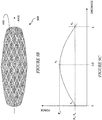
- a corresponding force-versus-distance graph for the anchor 300 is illustrated in Fig. 4B .
- the graph illustrates the different radially-outward forces provided by each of the anchoring elements 310 ( Fig. 4A ) versus its respective distance as measured along a central axis of the anchor 300.
- the greater radial force is provided by the central element 310b, having a representative force of F 2 .
- the corresponding force can be substantially constant across the axial length subtended by the second anchoring element 310b ( i.e., from L/3 to 2L/3, assuming all three elements are of equal length L/3).
- forces F 1 and F 3 provided by the adjacent first and third anchoring elements 310a, 310c are lesser forces, as shown in the graph ( e.g. , at region 320).
- the greater force F 2 corresponds to a securing force to hold the anchor in place when implanted; whereas, the lesser forces F 1 and F 3 correspond to transitional forces lessening the likelihood of damage to surrounding tissue.
- the structure of the anchoring elements 310 allows the elements to provide different forces along their respective sub-lengths.
- the anchoring elements 310 are radial springs, they have an associated spring constant.
- the radial force provided by the anchoring element 310 is thus a result of the spring constant and the amount of radial compression.
- Anchoring element configurations that allow for varied compression along the anchor sub-length will lead to a corresponding varied radial force.
- the outer anchoring elements 310a, 310c are each coupled at one end to the central anchoring element 310b, they may have a different diameter on each end.
- the central anchoring element 310b is stiffer, it may have a greater diameter than a less stiff element. In general, there is no limit to the number of anchoring elements that can be provided or to the particular stiffness profile desired.
- the securing force produced by the anchor can include a radial component directed outward and pressing against the walls of the surrounding lumen.
- the securing force also includes an axial component provided by a barb (not shown in all Figs.).
- the magnitude of the securing force preferably depends on the intended application being selected to sufficiently secure the anchor without being excessive. Limiting the maximum force is important as substantial forces acting against the luminal walls are more apt to traumatize the surrounding tissue.
- the radially-outward force of an anchor is varied by varying the stiffness (or compliance) of the anchor along its length.
- the stiffness or compliance
- the thickness of the anchor member can be varied to control the desired stiffness, such that a portion of the anchor is relatively stiff, whereas another portion of the anchor is relatively soft.
- the stiffer portion of the anchor can be used to distend that portion of the bodily lumen within which it is implanted.
- the stiffness is then reduced towards the proximal and distal ends of the anchor to reduce any trauma to the tissue of the bodily lumen.
- FIG. 5A a side view of a flexible intraluminal anchor 400' is illustrated in FIG. 5A .
- the anchor 400' is allowed to flex and bend.
- the joining members 420' are not necessary for embodiments in which the elements 410 are each coupled to the same tube or sleeve.
- the anchoring elements 410' are each formed from a respective continuous wire fashioned into the oscillating, wave-shaped pattern shown. Viewed along an axis (not shown), the anchor 400' would appear as an open circle or hoop. Wave-shaped anchors and related matters are described in U.S. application No. 10/858,852 filed on June 1, 2004 and claiming priority to U.S. Provisional Application Nos. 60/528,084 filed on December 9, 2003 and 60/544,527 filed on December 13, 2004 .
- the central anchoring element 410b' is formed from a relatively thick wire, such as a 0.58mm (0.023 inch) diameter Nitinol wire.
- the additional anchoring elements 410a', 410c' are formed from a thinner wire, such as a 0.36mm (0.014 inch) diameter Nitinol wire.
- the thicker wire results in a greater stiffness than the thinner wire.
- the central anchoring 410b' element provides a greater radially-outward force when compressed than either of the two surrounding anchoring elements 410a', 410c'.
- the spring rate can also be varied by altering the axial length of a wave-shaped anchoring element, shorter elements being stiffer than longer ones. Also, the spring rate can be varied by altering the number of oscillations for a give anchoring element, elements with more oscillations being stiffer.
- the wires can be formed from any suitable material, such as metals, metal alloys (e.g., stainless steel and Nitinol), and/or synthetic materials (e.g., plastic).
- the material is bio-compatible, although it is possible to use non bio-compatible material that is coated or encapsulated in a bio-compatible material.
- Anchoring can be accomplished using an interference fit between the intraluminal anchor and the inner walls of the lumen.
- anchoring is accomplished using at least one barb.
- at least one external barb 425' is attached to the central anchoring element 410b'.
- the barb 425' When implanted, the barb 425' is held in place within muscular tissue by the stiffness and corresponding radially-outward force of the 0.58mm (0.023 inch) diameter wire.
- the central anchor element 410b provides a substantial force to keep the barb 425' inserted into the surrounding tissue. Without the first and third anchoring elements 410a', 410c', the securing force provided by the middle anchoring element 410b' could lead to tissue irritation or even damage at the ends of the element 410b'.
- each of the anchoring elements described above can be formed into any number of different shapes.
- each of the anchoring elements is formed in a wave shape.
- a linear element i.e., a wire
- Such a wire form can be shaped on a cylindrical mandrel.
- the two ends of the wire are joined together (e.g., crimped, soldered, or chemically or thermally bonded) forming a continuous structure.
- An anchoring element thus formed provides a relatively small surface area in contact with the natural bodily lumen, while allowing the anchor to provide a relatively large diameter (e.g ., 25 to 50 or more millimeters for gastrointestinal applications).
- the oscillations result in relatively straight segments 412a, 412b (generally 412) interconnected at nodes 414a, 414b (generally 414).
- the nodes 414 When compressed in a radial direction, the nodes 414 flex allowing the relatively straight segments 412 to become more aligned with respect to each other.
- the diameter of the anchor 400' can be reduced substantially to allow for its insertion and/or removal through a relatively small diameter. For example, in some intestinal applications, a 50-millimeter diameter device is adapted to be inserted through a 12-millimeter diameter catheter. When released, the anchor 400' expands with spring force against the walls of the bodily lumen.
- the anchoring elements 410a', 410b', 410c' may be separated by respective distances S 1 , S 2 as shown, or one or more of the elements may be adjacent or even overlapping.
- An alternative example of a wave-shaped wire anchor 400" is illustrated in Fig. 5B .
- the anchoring 400" also includes multiple anchoring elements 410a", 410b", 410c" that may or may not be interconnected by joining members 420a", 420b". As shown, one or more of the anchoring elements 410a", 410b", 410c" can overlap another anchor element to varying degrees. At least one advantage of such an overlap is a reduction in the overall length of the anchor 400". Such an overlap can also be used to achieve a desired force-versus-distance profile of the anchor 400", leading to a more gradual transition of the forces distributed along the axis.
- FIG. 6 A side view of an alternative example of an intraluminal anchor 500 is illustrated in FIG. 6 .
- the anchor 500 includes multiple anchoring elements 510a, 510b, 510c, again shown as wave-shaped elements for illustrative purposes, that are interconnected to each other.
- the anchoring elements 510a, 510b, 510c can be interconnected by mechanical fasteners, chemical adhesives, thermal bonding, welding, soldering, and/or weaving. The interconnection may be fixed, or in the case of a weave, capable of longitudinal compression.
- the intraluminal anchor can be used to anchor an elongated tube within a natural bodily lumen.
- An exemplary device 600 including an intraluminal anchor, similar to the one described above in reference to FIG. 5A , and coupled to the proximal end of an elongated tube 615 is illustrated in FIG. 7 .
- the tube 615 may be rigid, semi-rigid or flexible. Gastrointestinal sleeves and related matters are described in U.S. application No. 10/339,786, filed January 9, 2003 , which claims the benefit of U.S. Provisional Application No. 60/430,321, filed December 2, 2002 ; and U.S. application No. 10/726,011, filed on December 2, 2003 , which claims the benefit of U.S. Provisional Application No. 60/512,145 filed October 17, 2003 .
- the anchoring elements 610a, 610b, 610c can be bonded to the tube (e.g., chemically bonded using an adhesive, or thermally bonded).
- the anchoring elements 610 can also be mechanically coupled to the elongated tube 615.
- the anchoring elements 610 can be coupled using a suture, a surgical staple, and/or by threading the anchoring element itself through perforations in the elongated tube.
- the anchoring elements 610 are encapsulated within the elongated tube 615.
- the elongated tube 615 can be formed as a sleeve. A portion the sleeve can then be used to encapsulate the anchoring elements by folding one end of the sleeve back upon itself to cover both the interior and exterior of the anchoring elements 610. The portions of the elongated tube forming the overlapping portion 617 can then be coupled together, thereby capturing the anchoring elements 610 and securing them in place with respect to each other and with respect to the elongated tube 615.
- the overlapping portions 617 of the tube 615 can be bonded together (e.g., chemically bonded using an adhesive, or thermally bonded).
- the overlapping portions 617 of the tube 615 can be mechanically fastened together.
- the overlapping portions 617 of the elongated tube 615 can be coupled together using sutures, staples, clasps, or any other suitable mechanical fastener.
- the anchor 600 includes barbs 620 that protrude externally from the anchor 600 to penetrate the surrounding tissue.
- the device 600 as implanted within a portion of an animal's intestine 630 illustrated in cross section. Shown are the intestinal wall 630 including an inner mucosal layer 632 in communication with the anchor 600 and a surrounding layer of muscular tissue 634.
- the barbs 620 are adapted to penetrate the mucosal layer 632 and into the muscular tissue 634 of the intestine 630. In some embodiments, the barbs 620 actually penetrate the outer walls of the intestine 630.
- the barbs 620 provide an axial securing force component, with the anchoring element 610b providing a securing force adapted to maintain the barbs into engagement with the muscular tissue 634.
- the anchoring element to which the barbs 620 are coupled should be relatively stiff.
- the stiffness of the supporting anchoring element 610b maintains a radial force ensuring that the barbs 620 are driven into the tissue.
- the stiffness is sufficient to force the supporting anchoring element 610b through the mucosal layer 632, abutting it to the layer of muscular tissue 634.
- the stiffness of the anchoring element 610b can lead to irritation and possibly damage to the surrounding tissue.
- additional anchoring elements 610a, 610c are provided on either side of the anchoring element 610b.
- the additional anchoring elements 610a, 610c are less stiff (i.e., softer) than the central anchoring element 610b.
- the transition between unanchored portions of the lumen and the stiff anchoring element 610b is spread over a larger surface area to achieve the desired anchoring force at the barbs 620 in a gradual manner.
- the additional anchoring elements 610a, 610c provide a strain relief on both sides of the stiff anchoring element 610b to minimize trauma to the tissue, as shown in Fig. 1B .
- FIG. 8 An exemplary embodiment of an intraluminal anchor anchoring an elongated flexible sleeve within the intestine of an animal is illustrated in Fig. 8 .
- a lower portion of the stomach 700 is shown terminating in a pyloric sphincter 705.
- Distal to the sphincter 705 is the proximal duodenum 715, sometimes referred to as the duodenal bulb.
- the device of Fig. 7 is implanted with the anchor being situated distal to the pyloric sphincter 705, preferably within the duodenal bulb 715.
- the sleeve 600 can extend through the duodenum 710 and into the jejunum 720.
- the radial force, or stiffness can be controlled by varying a physical property of the anchoring element.
- the elongated anchoring element can be formed from a tapered tube.
- the tube can be shaped to vary its wall thickness.
- the axial taper can be accomplished by injection moulding to a desired shape and/or by removing material from a solid elongated tube. The result in either case is an anchoring element having differing thicknesses along its central axis.
- Figure 9A illustrates a cross-sectional view of an exemplary tube 800 after having both ends tapered from a thicker middle section.
- the thinner ends 810 are achieved by removing extra material 820.
- a stainless steel or alloy (e.g., Nitinol) tube 800 can be shaped by grinding it and/or turning it on a lathe to selectably remove material along its length. As shown, the tube 800 can be tapered from a relatively thick portion along the tube middle, to a relatively thin portion at the tube's ends (with this approach, any conceivable profile is possible).
- the shaped tube 800 once tapered, can be further processed to form an expandable anchor.
- apertures 920 can be cut into the shaped tube 900 walls using a laser.
- the remaining portions of the shaped tube 910, once cut, can form a continuous structure such as the interconnected network of struts 910 shown, or even a wave structure as described above.
- the resulting structure provides an interior lumen 915, while also being radially compressible.
- a corresponding force-versus-distance profile for the exemplary tube 900 is illustrated in Fig. 9C .
Description
- Anchors are used in the treatment of patients to secure devices at a desired location within a natural bodily lumen. For example, anchors can be used to secure tubes within the digestive tract, such as intestinal sleeves. For example intestinal sleeves anchored within the gastrointestinal tract are described in
U.S. application No. 10/339,786 filed on January 9, 2003 U.S. Provisional Application No. 60/430,321 filed on December 2, 2002 10/858,852 filed on June. 16, 2004 U.S. Provisional Application Nos. 60/528,084 filed on December 9, 2003 60/544,527 filed on December 14, 2004 US2004/0093065 discloses a lining for insertion into a body lumen. - This invention is generally related to articles for anchoring within a natural bodily lumen.
- Unfortunately, stiff anchors can traumatize surrounding tissue. This is particularly true in biological applications in which the anchor operates against softer bodily tissues. A stiff anchor may be used within a bodily lumen, such as the intestine to prevent a medical device (e.g., a sleeve) from migrating therein. In some applications, the anchor includes barbs adapted to pierce a portion of the lumen. For the barbs to be effective, at least some of them must engage the tissue at all times. To accomplish this continued engagement, anchors provide a sufficient securing force adapted to maintain the barbs within the tissue. As this securing force can be substantial, tissue damage at the proximal and distal ends of the anchor are likely to occur.
- To anchor within a lumen, anchors generally apply at least some outward force directed toward the inner walls of the lumen. Depending upon the application, the anchoring force can vary from a minimal force (e.g., to hold hooks in position) to a more substantial force (e.g., forming an interference fit). In biological applications the inner walls of a lumen typically contain tissue that is soft and particularly vulnerable to irritation. Thus, in these applications a greater force increases the risk that the anchor will lead to trauma by way of irritation or even tissue damage.
- Such irritation and tissue damage are particular concerns for anchors adapted for use within the intestine. Unfortunately, the high mobility of the intestine and the nature of the forces acting on material within the intestine (i.e., peristalsis) complicate anchoring there. Thus, a more substantial force is typically required to secure an intestinal anchor in place.
- The present invention provides an intraluminal anchor, as defined in
claim 1. - The elongated anchor, when implanted, provides at least two different radial forces at respective positions along its length. These different radial forces act differently upon respective portions of the lumen when the device is implanted therein. Namely, at least one of the radial forces is primarily a securing force adapted to anchor within the lumen. The other radial force is a transitional force adapted to mitigate damage to the lumen. Further, when implanted, the intraluminal implant defines an interior lumen allowing for continued functioning of the natural bodily lumen.
- The elongated anchor can include plural anchoring elements each providing a respective radial force, at least one of the elements providing a different radial force from the others. By positioning each of the plural anchoring elements at a respective position along the length of the intraluminal anchor, the respective radial forces, including the different radial force, are disposed at different lengths along the lumen.
- The different radial force can be provided by forming one or more of the anchoring elements from a different material than the other anchoring elements. Preferably, the different materials provide different compliance values that produce different radial forces when implanted. Alternatively, or in addition, the different anchoring elements can be formed from the same material but in a different configuration, such as its shape or thickness.
- At least some of the anchoring elements can be coupled to each other. For example, in some embodiments at least one joining member is coupled between adjacent anchoring elements, the joining member coupling two or more anchoring elements together.
- In some embodiments having plural anchoring elements, at least one of the anchoring elements can be formed from an elongated wire. The elongated wire can be formed in any suitable shape, such as a helix or an oscillating (i.e., wave-shaped) pattern. The wave-shaped pattern distributes the respective radial force over the length of the anchoring element while also improving performance of the anchoring element's respective radial expansion and contraction.
- To further enhance its anchoring performance, the intraluminal anchor includes at least one external barb adapted to penetrate tissue of the natural bodily lumen. The external barb is located at a predetermined position along the length of the intraluminal anchor, the corresponding radial force acting to press the barb into the tissue. For example, in a multi-anchoring element embodiment, the at least one external barb is coupled to one of the anchoring elements. The force of the coupled anchoring element then acts to hold the barb within the tissue.
- In some embodiments, the external barb can be a bi-directional barb. Bi-directional barbs are particularly well suited for applications in which the intraluminal anchor is subjected to external forces acting in either direction along the lumen. Generally, the bi-directional barb includes a first barb segment adapted to oppose proximal movement and a second barb segment adapted to oppose distal movement. Such barbs are well suited to gastrointestinal applications in which the device is subjected to the substantial axial forces of peristalsis.
- Preferably, the anchor is radially collapsible for endoscopic insertion. The intraluminal anchor can also include a drawstring to facilitate repositioning and/or removal. The drawstring, for example, can be provided at a proximal end of the device and be adapted for engagement by a removal device, such as a hook. The drawstring, when engaged, can be pushed or pulled by the removal device, in opposition to the stationary intraluminal anchor, to at least partially collapse at least part of the intraluminal anchor. With a reduced diameter, the device can be removed through, or repositioned within, the lumen. In some embodiments, at least a portion of the device is drawn into a retrieval hood, sheath, or overtube prior to removal.
- The intraluminal anchor is coupled to an elongated tube at a proximal end of the tube, the tube being adapted to extend distally within the intestinal lumen. The elongated anchor can be coupled to the elongated tube in any of a number of different ways. For example, the anchor can be mechanically fastened using sutures, staples, or the like. Alternatively or in addition, the anchor can be bonded to the tube, using a chemical adhesive and/or heat welding. In some embodiments the tube is thin walled and flexible. For example, the tube can be formed as a sleeve having extremely thin and floppy walls, the sleeve tending to collapse upon itself. The anchor can be secured between at least two overlapping layers of the sleeve. The overlapping layers can then be attached to each other using any available fastening technique including bonding together at least a portion of the overlapping layers of the sleeve.
- In other embodiments, the elongated anchor can be formed from a homogeneous hollow tube. The thickness of the tube can be altered (i.e., tapered) along the length of the tube, such that different portions of the tube provide different spring forces. When implanted within a naturally bodily lumen, the tapered tube provides different forces along its length and therefore different forces along the bodily lumen according to the thickness of the tube. In some embodiments, the tapered tube can be further modified using known techniques (e.g., laser cutting) to promote radial expansion and contraction of the device.
- The foregoing and other objects, features and advantages of the invention will be apparent from the following more particular description of preferred embodiments of the invention, as illustrated in the accompanying drawings in which like reference characters refer to the same parts throughout the different views. The drawings are not necessarily to scale, emphasis instead being placed upon illustrating the principles of the invention.
-
Figures 2 to 6 and9 do not show embodiments of the invention. -
FIG. 1A is a schematic diagram illustrating a prior art intraluminal anchor implanted within a natural bodily lumen. -
FIG. 1B is a schematic diagram illustrating an example of an intraluminal anchor according to the principles of the invention implanted within a natural bodily lumen. -
FIG. 2 is a schematic diagram illustrating an example of an intraluminal anchor. -
FIG. 3 is a schematic diagram illustrating an example of a bendable, intraluminal anchor. -
FIG. 4A is a schematic diagram illustrating an alternative example of the intraluminal anchor shown inFIG. 1 . -
FIG. 4B is an exemplary radial-force profile for the intraluminal anchor ofFIG. 4A . -
FIGS. 5A and 5B are schematic diagrams illustrating alternative example of the intraluminal anchor shown inFIG. 2 having cross-linking members. -
FIG. 6 is a schematic diagram illustrating an alternative example of the intraluminal anchor shown inFIG. 4A having multiple coupled wave elements. -
Fig. 7 is a schematic diagram illustrating a cross-sectional view of an embodiment of the intraluminal anchor device shown inFig. 2 attached to a tube and implanted within a natural bodily lumen. -
Fig. 8 is a schematic diagram illustrating a cross-sectional view of the intraluminal anchor device shown inFig. 7 implanted within the proximal duodenum. -
Fig. 9A is a schematic diagram illustrating an example of a shaped tube. -
Fig. 9B is a schematic diagram illustrating an example of an intraluminal anchor formed from the shaped tube shown inFig. 9A . -
Fig. 9C is an exemplary radial-force profile for the intraluminal anchor ofFig. 9B . - A description of preferred embodiments of the invention follows.
- An anchor is adapted for anchoring within a natural bodily lumen while allowing continued functionality of the lumen and providing minimal trauma to the surrounding anatomy. Such an anchor provides a securing force acting upon the surrounding anatomy to hold the anchor fast, even in the presence of anticipated biological forces. For example, the securing force would hold a gastrointestinal anchor in position even in the presence of peristalsis. Anchoring against such forces, however, may require substantial securing force that could otherwise damage the surrounding tissue.
- A cross-section of a natural
bodily lumen 20 including ananchor 10b' is illustrated inFig. 1A . Generally, the lumen defines a natural diameter, D1, that may vary over time. The anchor provides a radially-outward securing force directed against the luminal walls. Depending upon the structure of theanchor 10b' and the compliance of the luminal walls, theanchor 10b' when implanted can increase the intraluminal diameter (i.e., D2) as shown. The sharp transition from the anchored region to the unsupported adjacent region applies a strain to the tissue, particularly at the ends of theanchor 25. As shown, tissue stretching can occur over a first distance Δ1. Such a strain can lead to irritation of the tissue or even damage over time. - To offset the possibility of damage due to the securing force, the anchor also provides a transitional force that is different from the securing force and acts upon an adjacent region of the surrounding anatomy. As shown in
FIG. 1B , ananchor 10b" providing a securing force is surrounded on either side by another anchoringelement 10a", 10c" providing a lesser, transitional force. The transitional force allows for a more gradual decrease in anchoring force from a central region along the length of the anchor and thus less trauma. Thus, the transition from an expanded diameter D2 to the natural luminal diameter D1 occurs over a second distance [Delta]2, that is greater than first distance [Delta] 1. By transitioning from unsupported tissue to anchored tissue using a softer anchoring element, the strain to the tissue is reduced, thereby reducing the likelihood of tissue irrigation and damage. - By applying different forces at different lengths along the natural bodily lumen, the securing force can be applied, or focused where needed, while the transitional force can distribute the pressure loading to the surrounding anatomy. In particular, the transitional force is a lesser force than the securing force, providing a gradual transition from the luminal region subjected to the securing force, to adjacent, unsupported luminal regions. The anchor is used in combination with a tube, such as a gastrointestinal sleeve, to secure the tube at a predetermined location within the bodily lumen.
-
FIG. 2 schematically illustrates an exemplary example of anintraluminal anchor 100. Theanchor 100 has an overall axial-length 'L' measured length-wise with respect to the lumen and defines aninterior channel 115 configured to allow continued operation of the lumen when implanted therein. For example, theanchor 100 can have a generally cylindrical shape, having a length 'L', a diameter 'D', and defining aninterior channel 115. When implanted, the anchor provides a radially-outward spring force directed against the adjacent walls of the natural bodily lumen (i.e., the anchor includes an annular, radial spring providing a force corresponding to a displacement of the spring along its radius). The radial force includes a securing force, sufficient to secure theanchor 100 in place under anticipated bodily forces. In particular, the outward radial force is varied along the length of the anchor to provide a transitional force, reducing the likelihood of damage to surrounding tissue. When implanted within a natural bodily lumen, the anchor provides a transition along the lumen from soft tissue, to a low compliance region (i.e., transitional force), to a higher compliance region (i.e., securing force), again to a low compliance region, and ultimately back to unsupported, soft tissue. - Generally, the anchor includes a spring providing the desired securing force. The force produced by the spring is defined by an associated spring rate relating to its compliance or stiffness. The spring rate can be determined by one or more anchor features including its type of material, material thickness, dimensions, and shape. As a radial spring, a greater force results from a greater radial displacement. For intraluminal applications, such a radial spring preferably has a relaxed diameter (i.e., no load diameter) that is greater than the largest anticipated intraluminal diameter. Thus, the implanted anchor is always subjected to a compressive force causing radial compression and leading to an opposing securing force. Compliant anchors are described in
U.S. application No. 11/147,992 filed on June 8, 2005 - The anchor remains sufficiently compliant, when implanted, to conform to the walls of the lumen over a full range of motion. For example, an anchor implanted within the proximal duodenum of an adult human may experience intraluminal diameter variations from about 25-millimeters or less, to greater than 50-millimeters.
- As suggested by
FIG. 2 , theanchor 100 can provide a varied force by using plural anchoring elements. For example, theanchor 100 can include three or moredifferent anchoring elements anchoring elements anchor 100 is determined as the sum of the sub-lengths of the anchoring elements and any distances provided therebetween. Each of the annular anchoring elements 110 can be sized and shaped to conform to the walls of the surrounding lumen with its opening collinearly aligned with a luminal axis. - In some examples, the anchoring elements 110 are coupled together using a respective cross-linking, or joining
member - An example of a flexible
elongated anchor 200 is illustrated inFig. 3 . Theelongated anchor 200 can include more than oneanchoring element anchor 200 may include joiningmembers anchor 200, allowing the anchor to bend towards that side. - An alternative example of an
intraluminal anchor 300 is illustrated inFig. 4A . Theanchor 300 includesmultiple anchoring elements anchor 300 is illustrated inFig. 4B . In particular, the graph illustrates the different radially-outward forces provided by each of the anchoring elements 310 (Fig. 4A ) versus its respective distance as measured along a central axis of theanchor 300. As shown for the exemplary embodiment ofFig. 4A , the greater radial force is provided by thecentral element 310b, having a representative force of F2. The corresponding force can be substantially constant across the axial length subtended by thesecond anchoring element 310b (i.e., from L/3 to 2L/3, assuming all three elements are of equal length L/3). Similarly, forces F1 and F3 provided by the adjacent first andthird anchoring elements - In some example, however, the structure of the anchoring elements 310 allows the elements to provide different forces along their respective sub-lengths. As the anchoring elements 310 are radial springs, they have an associated spring constant. The radial force provided by the anchoring element 310 is thus a result of the spring constant and the amount of radial compression. Anchoring element configurations that allow for varied compression along the anchor sub-length will lead to a corresponding varied radial force. For example, if the
outer anchoring elements central anchoring element 310b, they may have a different diameter on each end. As thecentral anchoring element 310b is stiffer, it may have a greater diameter than a less stiff element. In general, there is no limit to the number of anchoring elements that can be provided or to the particular stiffness profile desired. - The securing force produced by the anchor can include a radial component directed outward and pressing against the walls of the surrounding lumen. The securing force also includes an axial component provided by a barb (not shown in all Figs.). The magnitude of the securing force preferably depends on the intended application being selected to sufficiently secure the anchor without being excessive. Limiting the maximum force is important as substantial forces acting against the luminal walls are more apt to traumatize the surrounding tissue.
- In some example, the radially-outward force of an anchor is varied by varying the stiffness (or compliance) of the anchor along its length. Such a feature provides for greater flexibility in tailoring the anchor to its intended delivery location. For example, the thickness of the anchor member can be varied to control the desired stiffness, such that a portion of the anchor is relatively stiff, whereas another portion of the anchor is relatively soft. In this manner, the stiffer portion of the anchor can be used to distend that portion of the bodily lumen within which it is implanted. To reduce irritation, the stiffness is then reduced towards the proximal and distal ends of the anchor to reduce any trauma to the tissue of the bodily lumen.
- For example, a side view of a flexible intraluminal anchor 400' is illustrated in
FIG. 5A . By usingdifferent anchoring elements 410a', 410b', 410c', interconnected by joiningmembers 420a', 420b'(generally 420') as shown, the anchor 400' is allowed to flex and bend. The joining members 420' are not necessary for embodiments in which the elements 410 are each coupled to the same tube or sleeve. The anchoring elements 410' are each formed from a respective continuous wire fashioned into the oscillating, wave-shaped pattern shown. Viewed along an axis (not shown), the anchor 400' would appear as an open circle or hoop. Wave-shaped anchors and related matters are described inU.S. application No. 10/858,852 filed on June 1, 2004 U.S. Provisional Application Nos. 60/528,084 filed on December 9, 2003 60/544,527 filed on December 13, 2004 - In one example the
central anchoring element 410b' is formed from a relatively thick wire, such as a 0.58mm (0.023 inch) diameter Nitinol wire. Theadditional anchoring elements 410a', 410c' are formed from a thinner wire, such as a 0.36mm (0.014 inch) diameter Nitinol wire. Using wires formed from the same material, the thicker wire results in a greater stiffness than the thinner wire. Thus, thecentral anchoring 410b' element provides a greater radially-outward force when compressed than either of the two surroundinganchoring elements 410a', 410c'. The spring rate can also be varied by altering the axial length of a wave-shaped anchoring element, shorter elements being stiffer than longer ones. Also, the spring rate can be varied by altering the number of oscillations for a give anchoring element, elements with more oscillations being stiffer. - The wires can be formed from any suitable material, such as metals, metal alloys (e.g., stainless steel and Nitinol), and/or synthetic materials (e.g., plastic). Preferably, the material is bio-compatible, although it is possible to use non bio-compatible material that is coated or encapsulated in a bio-compatible material. Anchoring can be accomplished using an interference fit between the intraluminal anchor and the inner walls of the lumen. In addition, anchoring is accomplished using at least one barb. In the exemplary embodiment, at least one external barb 425' is attached to the
central anchoring element 410b'. When implanted, the barb 425' is held in place within muscular tissue by the stiffness and corresponding radially-outward force of the 0.58mm (0.023 inch) diameter wire. Thecentral anchor element 410b provides a substantial force to keep the barb 425' inserted into the surrounding tissue. Without the first andthird anchoring elements 410a', 410c', the securing force provided by themiddle anchoring element 410b' could lead to tissue irritation or even damage at the ends of theelement 410b'. - The anchoring elements described above can be formed into any number of different shapes. In some example, each of the anchoring elements is formed in a wave shape. Thus, a linear element (i.e., a wire) is contoured into an oscillating manner along a cylindrical surface at a distance (i.e., a radius) from a central axis. Such a wire form can be shaped on a cylindrical mandrel. The two ends of the wire are joined together (e.g., crimped, soldered, or chemically or thermally bonded) forming a continuous structure. An anchoring element thus formed provides a relatively small surface area in contact with the natural bodily lumen, while allowing the anchor to provide a relatively large diameter (e.g., 25 to 50 or more millimeters for gastrointestinal applications). The oscillations result in relatively
straight segments nodes - The
anchoring elements 410a', 410b', 410c' may be separated by respective distances S1, S2 as shown, or one or more of the elements may be adjacent or even overlapping. An alternative example of a wave-shapedwire anchor 400" is illustrated inFig. 5B . The anchoring 400" also includesmultiple anchoring elements 410a", 410b", 410c" that may or may not be interconnected by joiningmembers 420a", 420b". As shown, one or more of theanchoring elements 410a", 410b", 410c" can overlap another anchor element to varying degrees. At least one advantage of such an overlap is a reduction in the overall length of theanchor 400". Such an overlap can also be used to achieve a desired force-versus-distance profile of theanchor 400", leading to a more gradual transition of the forces distributed along the axis. - A side view of an alternative example of an
intraluminal anchor 500 is illustrated inFIG. 6 . Theanchor 500 includesmultiple anchoring elements anchoring elements - As described above, the intraluminal anchor can be used to anchor an elongated tube within a natural bodily lumen. An
exemplary device 600 including an intraluminal anchor, similar to the one described above in reference toFIG. 5A , and coupled to the proximal end of anelongated tube 615 is illustrated inFIG. 7 . Thetube 615 may be rigid, semi-rigid or flexible. Gastrointestinal sleeves and related matters are described inU.S. application No. 10/339,786, filed January 9, 2003 U.S. Provisional Application No. 60/430,321, filed December 2, 2002 U.S. application No. 10/726,011, filed on December 2, 2003 U.S. Provisional Application No. 60/512,145 filed October 17, 2003 - The
anchoring elements elongated tube 615. For example, the anchoring elements 610 can be coupled using a suture, a surgical staple, and/or by threading the anchoring element itself through perforations in the elongated tube. - In some embodiments, the anchoring elements 610 are encapsulated within the
elongated tube 615. For example, theelongated tube 615 can be formed as a sleeve. A portion the sleeve can then be used to encapsulate the anchoring elements by folding one end of the sleeve back upon itself to cover both the interior and exterior of the anchoring elements 610. The portions of the elongated tube forming the overlappingportion 617 can then be coupled together, thereby capturing the anchoring elements 610 and securing them in place with respect to each other and with respect to theelongated tube 615. For example, the overlappingportions 617 of thetube 615 can be bonded together (e.g., chemically bonded using an adhesive, or thermally bonded). Alternatively or in addition, the overlappingportions 617 of thetube 615 can be mechanically fastened together. For example, the overlappingportions 617 of theelongated tube 615 can be coupled together using sutures, staples, clasps, or any other suitable mechanical fastener. - As shown, the
anchor 600 includesbarbs 620 that protrude externally from theanchor 600 to penetrate the surrounding tissue. For illustrative purposes, thedevice 600 as implanted within a portion of an animal'sintestine 630 illustrated in cross section. Shown are theintestinal wall 630 including aninner mucosal layer 632 in communication with theanchor 600 and a surrounding layer ofmuscular tissue 634. Thebarbs 620 are adapted to penetrate themucosal layer 632 and into themuscular tissue 634 of theintestine 630. In some embodiments, thebarbs 620 actually penetrate the outer walls of theintestine 630. Thus, thebarbs 620 provide an axial securing force component, with the anchoringelement 610b providing a securing force adapted to maintain the barbs into engagement with themuscular tissue 634. - To ensure that the
barbs 620 remain secured to the muscular tissue during implantation, the anchoring element to which thebarbs 620 are coupled should be relatively stiff. Thus, the stiffness of the supportinganchoring element 610b maintains a radial force ensuring that thebarbs 620 are driven into the tissue. In some embodiments, the stiffness is sufficient to force the supportinganchoring element 610b through themucosal layer 632, abutting it to the layer ofmuscular tissue 634. - In some applications, however, the stiffness of the
anchoring element 610b can lead to irritation and possibly damage to the surrounding tissue. To reduce the possibility of such irritation or damage,additional anchoring elements anchoring element 610b. Preferably, theadditional anchoring elements central anchoring element 610b. In this manner, the transition between unanchored portions of the lumen and thestiff anchoring element 610b is spread over a larger surface area to achieve the desired anchoring force at thebarbs 620 in a gradual manner. Thus, theadditional anchoring elements stiff anchoring element 610b to minimize trauma to the tissue, as shown inFig. 1B . - An exemplary embodiment of an intraluminal anchor anchoring an elongated flexible sleeve within the intestine of an animal is illustrated in
Fig. 8 . A lower portion of thestomach 700 is shown terminating in apyloric sphincter 705. Distal to thesphincter 705 is theproximal duodenum 715, sometimes referred to as the duodenal bulb. The device ofFig. 7 is implanted with the anchor being situated distal to thepyloric sphincter 705, preferably within theduodenal bulb 715. Thesleeve 600 can extend through theduodenum 710 and into thejejunum 720. - As described above in reference to wire anchoring elements, the radial force, or stiffness can be controlled by varying a physical property of the anchoring element. This approach can also be extended beyond wire examples. For example, the elongated anchoring element can be formed from a tapered tube. To vary the radial force, or stiffness, the tube can be shaped to vary its wall thickness. The axial taper can be accomplished by injection moulding to a desired shape and/or by removing material from a solid elongated tube. The result in either case is an anchoring element having differing thicknesses along its central axis.
Figure 9A illustrates a cross-sectional view of anexemplary tube 800 after having both ends tapered from a thicker middle section. Thus, the thinner ends 810 are achieved by removingextra material 820. For example, a stainless steel or alloy (e.g., Nitinol)tube 800 can be shaped by grinding it and/or turning it on a lathe to selectably remove material along its length. As shown, thetube 800 can be tapered from a relatively thick portion along the tube middle, to a relatively thin portion at the tube's ends (with this approach, any conceivable profile is possible). - The shaped
tube 800, once tapered, can be further processed to form an expandable anchor. For example, referring toFig. 9B , apertures 920 can be cut into the shapedtube 900 walls using a laser. The remaining portions of the shaped tube 910, once cut, can form a continuous structure such as the interconnected network of struts 910 shown, or even a wave structure as described above. Again, the resulting structure provides aninterior lumen 915, while also being radially compressible. A corresponding force-versus-distance profile for theexemplary tube 900 is illustrated inFig. 9C . - As will be appreciated by those of skill in the art, there are many potential variations to these methods and articles. Those variations are encompassed by this invention.
- While this invention has been particularly shown and described with references to preferred embodiments thereof, it will be understood by those skilled in the art that various changes in form and details may be made therein without departing from the scope of the invention encompassed by the appended claim.
Claims (18)
- An intraluminal anchor (610) comprising:an elongated anchor adapted for implanting within an intestinal lumen, a central axis of the elongated anchor adapted for alignment with the intestinal lumen, the elongated anchor including:a primary anchoring region adapted to expand against the lumen; anda secondary anchoring region disposed at either side of the primary anchoring region also adapted to expand against the lumen, the primary anchoring region expanding to a greater extent than an outer end of each of the secondary anchoring regions;characterised by at least one external barb (620) positioned at the primary anchoring region and adapted to penetrate muscle of the intestinal lumen, the expanding against the lumen adapted to hold the barb (620) within the muscle; and
an elongated tube (615) coupled at its proximal end to the elongated anchor, the tube (615) adapted to extend distally within the intestinal lumen;
wherein the elongated anchor remains sufficiently compliant, when implanted, to conform to the walls of the intestinal lumen over a full range of motion, and is adapted to experience intraluminal diameter variations from 25 millimeters or less to greater than 50 millimeters. - The intraluminal anchor (610) of claim 1 wherein the elongated anchor comprises a plurality of anchoring elements (610), at least one (610b) of the anchoring elements (610) relating to the primary anchoring region and at least two other (610a,610c) of the anchoring elements (610) relating to the secondary anchoring regions.
- The intraluminal anchor (610) of claim 2, wherein the anchoring element (610b) relating to the primary anchoring region and the at least two other (610a,610c) of the anchoring elements (610) relating to the secondary anchoring regions comprise different materials.
- The intraluminal anchor (610) of claim 2, wherein the anchoring element (610b) relating to the primary anchoring region and the at least two other (610a,610c) of the anchoring elements (610) relating to the secondary anchoring regions comprise substantially the same material having a different thickness.
- The intraluminal anchor (610) of claim 2, wherein the at least one of the plurality of anchoring elements (610) is formed from an elongated wire.
- The intraluminal anchor (610) of claim 2, wherein at least one of the plurality of anchoring elements (610) is a wave-shaped element.
- The intraluminal anchor (610) of claim 2, wherein the at least one (610b) of the plurality of anchoring elements (610) comprises the at least one external barb (620) in the primary anchoring region adapted to penetrate muscular tissue of the intestinal lumen, the respective anchoring element (610b) expanding against the lumen and adapted to hold the barb (620) within the muscular tissue.
- The intraluminal anchor (610) of claim 7, wherein the external barb (620) is a bi-directional barb, comprising a first barb segment adapted to oppose proximal movement and a second barb segment adapted to oppose distal movement.
- The intraluminal anchor (610) of claim 2, further comprising at least one joining member coupled between at least two of the plurality of anchoring elements (610).
- The intraluminal anchor (610) of claim 1, wherein the elongated anchor is adapted to be anchored in the proximal duodenum, the tube (615) extending distally within the intestine.
- The intraluminal anchor (610) of claim 10, wherein the elongated tube (615) is thin-walled, collapsing upon itself.
- The intraluminal anchor (610) of claim 1, wherein the external barb (620) is a bi-directional barb, comprising a first barb segment adapted to oppose proximal movement and a second barb segment adapted to oppose distal movement.
- The intraluminal anchor (610) of claim 1, wherein the elongated tube (615) is thin-walled, collapsing upon itself.
- The intraluminal anchor (610) of claim 1, wherein the elongated anchoring element is coupled to the tube (615) between overlapping layers (617) of the tube (615).
- The intraluminal anchor (610) of claim 1, wherein the anchor is radially collapsible for endoscopic insertion.
- The intraluminal anchor (610) of claim 1, wherein the elongated anchor is formed from a homogeneous hollow tube having a tube wall of differing thickness along its length, the tube wall defining apertures adapted to allow radial variation of the tube.
- The intraluminal anchor (610) of claim 1, wherein the primary and secondary anchoring regions comprise different spring rates.
- The intraluminal anchor (610) of claim 1, wherein the primary anchoring region is central.
Priority Applications (1)
| Application Number | Priority Date | Filing Date | Title |
|---|---|---|---|
| EP16205480.3A EP3195829A1 (en) | 2004-09-17 | 2005-09-16 | Gastrointestinal achor |
Applications Claiming Priority (2)
| Application Number | Priority Date | Filing Date | Title |
|---|---|---|---|
| US61103804P | 2004-09-17 | 2004-09-17 | |
| PCT/US2005/033220 WO2006034062A1 (en) | 2004-09-17 | 2005-09-16 | Gastrointestinal anchor |
Related Child Applications (1)
| Application Number | Title | Priority Date | Filing Date |
|---|---|---|---|
| EP16205480.3A Division EP3195829A1 (en) | 2004-09-17 | 2005-09-16 | Gastrointestinal achor |
Publications (2)
| Publication Number | Publication Date |
|---|---|
| EP1799145A1 EP1799145A1 (en) | 2007-06-27 |
| EP1799145B1 true EP1799145B1 (en) | 2016-12-21 |
Family
ID=35610001
Family Applications (2)
| Application Number | Title | Priority Date | Filing Date |
|---|---|---|---|
| EP05797460.2A Not-in-force EP1799145B1 (en) | 2004-09-17 | 2005-09-16 | Gastrointestinal anchor |
| EP16205480.3A Withdrawn EP3195829A1 (en) | 2004-09-17 | 2005-09-16 | Gastrointestinal achor |
Family Applications After (1)
| Application Number | Title | Priority Date | Filing Date |
|---|---|---|---|
| EP16205480.3A Withdrawn EP3195829A1 (en) | 2004-09-17 | 2005-09-16 | Gastrointestinal achor |
Country Status (5)
| Country | Link |
|---|---|
| US (3) | US7815591B2 (en) |
| EP (2) | EP1799145B1 (en) |
| JP (1) | JP2008513129A (en) |
| AU (1) | AU2005287010B2 (en) |
| WO (1) | WO2006034062A1 (en) |
Families Citing this family (155)
| Publication number | Priority date | Publication date | Assignee | Title |
|---|---|---|---|---|
| CN101810521B (en) | 2001-08-27 | 2015-05-13 | 辛尼科有限责任公司 | Satiation devices and methods |
| US7837669B2 (en) * | 2002-11-01 | 2010-11-23 | Valentx, Inc. | Devices and methods for endolumenal gastrointestinal bypass |
| US9060844B2 (en) | 2002-11-01 | 2015-06-23 | Valentx, Inc. | Apparatus and methods for treatment of morbid obesity |
| US20060015125A1 (en) * | 2004-05-07 | 2006-01-19 | Paul Swain | Devices and methods for gastric surgery |
| US7794447B2 (en) * | 2002-11-01 | 2010-09-14 | Valentx, Inc. | Gastrointestinal sleeve device and methods for treatment of morbid obesity |
| US20090149871A9 (en) * | 2002-11-01 | 2009-06-11 | Jonathan Kagan | Devices and methods for treating morbid obesity |
| US7037344B2 (en) * | 2002-11-01 | 2006-05-02 | Valentx, Inc. | Apparatus and methods for treatment of morbid obesity |
| US7678068B2 (en) * | 2002-12-02 | 2010-03-16 | Gi Dynamics, Inc. | Atraumatic delivery devices |
| US7695446B2 (en) | 2002-12-02 | 2010-04-13 | Gi Dynamics, Inc. | Methods of treatment using a bariatric sleeve |
| US7608114B2 (en) | 2002-12-02 | 2009-10-27 | Gi Dynamics, Inc. | Bariatric sleeve |
| US7025791B2 (en) | 2002-12-02 | 2006-04-11 | Gi Dynamics, Inc. | Bariatric sleeve |
| US7766973B2 (en) | 2005-01-19 | 2010-08-03 | Gi Dynamics, Inc. | Eversion resistant sleeves |
| US20070032879A1 (en) * | 2002-12-02 | 2007-02-08 | Levine Andy H | Anti-buckling sleeve |
| WO2004049982A2 (en) | 2002-12-02 | 2004-06-17 | Gi Dynamics, Inc. | Bariatric sleeve |
| ATE454864T1 (en) * | 2003-03-28 | 2010-01-15 | Gi Dynamics Inc | TUBE FOR DELAYED INTRODUCTION OF ENZYMES INTO THE INTESTINAL |
| DE602004019505D1 (en) * | 2003-03-28 | 2009-04-02 | Gi Dynamics Inc | DEVICES AGAINST GRAVITY |
| US8206456B2 (en) | 2003-10-10 | 2012-06-26 | Barosense, Inc. | Restrictive and/or obstructive implant system for inducing weight loss |
| US20050247320A1 (en) | 2003-10-10 | 2005-11-10 | Stack Richard S | Devices and methods for retaining a gastro-esophageal implant |
| US7815589B2 (en) * | 2003-12-09 | 2010-10-19 | Gi Dynamics, Inc. | Methods and apparatus for anchoring within the gastrointestinal tract |
| US20060212042A1 (en) * | 2005-03-17 | 2006-09-21 | Lamport Ronald B | Removal and repositioning device |
| US8057420B2 (en) | 2003-12-09 | 2011-11-15 | Gi Dynamics, Inc. | Gastrointestinal implant with drawstring |
| US8585771B2 (en) | 2004-02-26 | 2013-11-19 | Endosphere, Inc. | Methods and devices to curb appetite and/or to reduce food intake |
| US8147561B2 (en) | 2004-02-26 | 2012-04-03 | Endosphere, Inc. | Methods and devices to curb appetite and/or reduce food intake |
| US7931693B2 (en) * | 2004-02-26 | 2011-04-26 | Endosphere, Inc. | Method and apparatus for reducing obesity |
| EP1750595A4 (en) | 2004-05-07 | 2008-10-22 | Valentx Inc | Devices and methods for attaching an endolumenal gastrointestinal implant |
| WO2006016894A1 (en) * | 2004-07-09 | 2006-02-16 | Gi Dynamics, Inc. | Methods and devices for placing a gastrointestinal sleeve |
| EP1799145B1 (en) | 2004-09-17 | 2016-12-21 | GI Dynamics, Inc. | Gastrointestinal anchor |
| EP1804888B1 (en) | 2004-10-15 | 2013-12-25 | Bfkw, Llc | Bariatric device |
| KR101696006B1 (en) | 2004-10-15 | 2017-01-13 | 비에프케이더블유, 엘엘씨 | Bariatric device and method for recipient with altered anatomy |
| US7771382B2 (en) | 2005-01-19 | 2010-08-10 | Gi Dynamics, Inc. | Resistive anti-obesity devices |
| US7976488B2 (en) | 2005-06-08 | 2011-07-12 | Gi Dynamics, Inc. | Gastrointestinal anchor compliance |
| US20070049801A1 (en) * | 2005-08-24 | 2007-03-01 | Lamport Ronald B | Endoscope accessory |
| US7881797B2 (en) * | 2006-04-25 | 2011-02-01 | Valentx, Inc. | Methods and devices for gastrointestinal stimulation |
| US9060835B2 (en) | 2006-05-26 | 2015-06-23 | Endosphere, Inc. | Conformationally-stabilized intraluminal device for medical applications |
| US7819836B2 (en) | 2006-06-23 | 2010-10-26 | Gi Dynamics, Inc. | Resistive anti-obesity devices |
| WO2008005510A2 (en) * | 2006-07-06 | 2008-01-10 | Synecor, Llc | Systems and methods for restoring function of diseased bowel |
| US10350099B2 (en) | 2006-09-01 | 2019-07-16 | Ethicon Endo-Surgery, Inc. | Devices and methods for anchoring an endoluminal sleeve in the GI tract |
| ES2527923T3 (en) | 2006-09-02 | 2015-02-02 | Barosense, Inc. | Intestinal sleeves and associated deployment systems and methods |
| WO2008100984A2 (en) | 2007-02-14 | 2008-08-21 | Sentinel Group, Llc | Mucosal capture fixation of medical device |
| US8529431B2 (en) | 2007-02-14 | 2013-09-10 | Bfkw, Llc | Bariatric device and method |
| US8801647B2 (en) * | 2007-02-22 | 2014-08-12 | Gi Dynamics, Inc. | Use of a gastrointestinal sleeve to treat bariatric surgery fistulas and leaks |
| US10238518B2 (en) | 2007-02-27 | 2019-03-26 | Agt Inc. | Implantable weight control device |
| BRPI0721499A2 (en) * | 2007-03-23 | 2013-01-08 | Invatec Technology Ct Gmbh | endoluminal prosthesis |
| EP2134303A1 (en) * | 2007-03-29 | 2009-12-23 | Jaime Vargas | Intragastric implant devices |
| US20080255678A1 (en) * | 2007-04-13 | 2008-10-16 | Cully Edward H | Medical apparatus and method of making the same |
| US9717584B2 (en) * | 2007-04-13 | 2017-08-01 | W. L. Gore & Associates, Inc. | Medical apparatus and method of making the same |
| US9642693B2 (en) * | 2007-04-13 | 2017-05-09 | W. L. Gore & Associates, Inc. | Medical apparatus and method of making the same |
| EP2164558A4 (en) * | 2007-06-08 | 2010-08-04 | Valentx Inc | Methods and devices for intragastric support of functional or prosthetic gastrointestinal devices |
| US20090012544A1 (en) * | 2007-06-08 | 2009-01-08 | Valen Tx, Inc. | Gastrointestinal bypass sleeve as an adjunct to bariatric surgery |
| MX2009013568A (en) * | 2007-06-11 | 2010-04-21 | Valentx Inc | Endoscopic delivery devices and methods. |
| US20110137227A1 (en) * | 2007-07-16 | 2011-06-09 | Mckinley James T | Methods and devices for delivering or delaying lipids within a duodenum |
| WO2009036244A1 (en) | 2007-09-12 | 2009-03-19 | Endometabolic Solutions, Inc. | Devices and methods for treatment of obesity |
| US20090182355A1 (en) * | 2007-12-20 | 2009-07-16 | Levine Andy H | Porous barbs for long-term anchoring in the gastrointestinal tract |
| EP2240092A4 (en) * | 2008-02-01 | 2015-05-06 | Medical And Surgical Review P C | Methods and devices for anchoring a gastroenterologic sleeve |
| US8182442B2 (en) * | 2008-04-09 | 2012-05-22 | Electrocore Llc | Pyloric valve devices and methods |
| WO2009126268A1 (en) | 2008-04-09 | 2009-10-15 | Endocore Llc | Pyloric valve |
| US10350050B2 (en) * | 2008-05-01 | 2019-07-16 | Ethicon Endo-Surgery, Inc. | Method for gastric volume reduction surgery |
| EP2323569B1 (en) | 2008-05-15 | 2017-10-04 | Cook Medical Technologies LLC | Device for accessing a bodily opening |
| JP2012504031A (en) * | 2008-09-29 | 2012-02-16 | カルディアック バルブ テクノロジーズ,インコーポレーテッド | Heart valve |
| WO2010041040A1 (en) * | 2008-10-10 | 2010-04-15 | Veryan Medical Limited | A stent suitable for deployment in a blood vessel |
| WO2010041039A1 (en) | 2008-10-10 | 2010-04-15 | Veryan Medical Limited | A medical device suitable for location in a body lumen |
| GB2467097B (en) | 2008-11-06 | 2011-01-12 | Cook William Europ | Stent member |
| US8734502B2 (en) * | 2008-12-17 | 2014-05-27 | Cook Medical Technologies Llc | Tapered stent and flexible prosthesis |
| US8267857B2 (en) * | 2009-01-30 | 2012-09-18 | Cook Medical Technologies Llc | Expandable port for accessing a bodily opening |
| FR2941858B1 (en) * | 2009-02-10 | 2011-03-11 | Charam Khosrvaninejad | SURGICAL DEVICE CAPABLE OF REALIZING THE TEMPORARY PROTECTION OF ANASTOMOSIS |
| US9173760B2 (en) | 2009-04-03 | 2015-11-03 | Metamodix, Inc. | Delivery devices and methods for gastrointestinal implants |
| US9278019B2 (en) | 2009-04-03 | 2016-03-08 | Metamodix, Inc | Anchors and methods for intestinal bypass sleeves |
| US8702641B2 (en) | 2009-04-03 | 2014-04-22 | Metamodix, Inc. | Gastrointestinal prostheses having partial bypass configurations |
| US8211186B2 (en) | 2009-04-03 | 2012-07-03 | Metamodix, Inc. | Modular gastrointestinal prostheses |
| US10456276B2 (en) | 2009-05-08 | 2019-10-29 | Veryan Medical Limited | Medical device suitable for location in a body lumen |
| US8834361B2 (en) | 2009-05-15 | 2014-09-16 | Cook Medical Technologies Llc | Systems, devices and methods for accessing a bodily opening |
| US20100305590A1 (en) * | 2009-05-29 | 2010-12-02 | Gi Dynamics, Inc. | Transpyloric Anchoring |
| AU2010271294B2 (en) | 2009-07-10 | 2015-09-03 | Metamodix, Inc. | External anchoring configurations for modular gastrointestinal prostheses |
| US8475525B2 (en) * | 2010-01-22 | 2013-07-02 | 4Tech Inc. | Tricuspid valve repair using tension |
| US9307980B2 (en) | 2010-01-22 | 2016-04-12 | 4Tech Inc. | Tricuspid valve repair using tension |
| US10058323B2 (en) | 2010-01-22 | 2018-08-28 | 4 Tech Inc. | Tricuspid valve repair using tension |
| CN102917666B (en) | 2010-03-26 | 2015-07-29 | Ibis医药股份有限公司 | Gastric implanting device |
| US20120046731A1 (en) * | 2010-04-14 | 2012-02-23 | Abbott Vascular | Intraluminal scaffold with conforming axial strut |
| US8579964B2 (en) | 2010-05-05 | 2013-11-12 | Neovasc Inc. | Transcatheter mitral valve prosthesis |
| US20120004677A1 (en) | 2010-05-21 | 2012-01-05 | Balbierz Daniel J | Tissue-acquisition and fastening devices and methods |
| US10010439B2 (en) | 2010-06-13 | 2018-07-03 | Synerz Medical, Inc. | Intragastric device for treating obesity |
| US9526648B2 (en) | 2010-06-13 | 2016-12-27 | Synerz Medical, Inc. | Intragastric device for treating obesity |
| US8628554B2 (en) | 2010-06-13 | 2014-01-14 | Virender K. Sharma | Intragastric device for treating obesity |
| US10420665B2 (en) | 2010-06-13 | 2019-09-24 | W. L. Gore & Associates, Inc. | Intragastric device for treating obesity |
| EP2595693B1 (en) | 2010-07-22 | 2015-03-04 | Endobetix Ltd | Pancreatiobiliary diversion device |
| AU2012236277B2 (en) * | 2011-03-30 | 2016-03-03 | Boston Scientific Scimed, Inc. | Implants, tools, and methods for treatment of pelvic conditions |
| US9744033B2 (en) | 2011-04-01 | 2017-08-29 | W.L. Gore & Associates, Inc. | Elastomeric leaflet for prosthetic heart valves |
| US9554897B2 (en) | 2011-04-28 | 2017-01-31 | Neovasc Tiara Inc. | Methods and apparatus for engaging a valve prosthesis with tissue |
| US9308087B2 (en) | 2011-04-28 | 2016-04-12 | Neovasc Tiara Inc. | Sequentially deployed transcatheter mitral valve prosthesis |
| ES2694824T3 (en) | 2011-05-20 | 2018-12-27 | Bfkw, Llc | Intraluminal device with improved anti-migration |
| US10117765B2 (en) | 2011-06-14 | 2018-11-06 | W.L. Gore Associates, Inc | Apposition fiber for use in endoluminal deployment of expandable implants |
| FR2978345B1 (en) | 2011-07-25 | 2013-08-30 | Charam Khosrovaninejad | SURGICAL DEVICE FOR ANCHOR CONTROL IN INTESTINES. |
| US8870947B2 (en) | 2011-09-16 | 2014-10-28 | W.L. Gore & Associates, Inc. | Medical device fixation anchors |
| US9554806B2 (en) | 2011-09-16 | 2017-01-31 | W. L. Gore & Associates, Inc. | Occlusive devices |
| CN103974741A (en) * | 2011-09-27 | 2014-08-06 | Ibis医药股份有限公司 | Intragastric implant devices |
| US9320623B2 (en) | 2011-10-04 | 2016-04-26 | Cook Medical Technologies Llc | Reduced wire profile stent |
| US9782282B2 (en) | 2011-11-14 | 2017-10-10 | W. L. Gore & Associates, Inc. | External steerable fiber for use in endoluminal deployment of expandable devices |
| US9877858B2 (en) | 2011-11-14 | 2018-01-30 | W. L. Gore & Associates, Inc. | External steerable fiber for use in endoluminal deployment of expandable devices |
| WO2013134227A1 (en) | 2012-03-06 | 2013-09-12 | Bfkw, Llc | Intraluminal device delivery technique |
| US9375308B2 (en) | 2012-03-13 | 2016-06-28 | W. L. Gore & Associates, Inc. | External steerable fiber for use in endoluminal deployment of expandable devices |
| US8882828B2 (en) * | 2012-04-27 | 2014-11-11 | Medtronic Vascular, Inc. | Ring on a closed web stent-graft for use in tip capture |
| US9345573B2 (en) | 2012-05-30 | 2016-05-24 | Neovasc Tiara Inc. | Methods and apparatus for loading a prosthesis onto a delivery system |
| US9681975B2 (en) | 2012-05-31 | 2017-06-20 | Valentx, Inc. | Devices and methods for gastrointestinal bypass |
| US20130324906A1 (en) | 2012-05-31 | 2013-12-05 | Valen Tx, Inc. | Devices and methods for gastrointestinal bypass |
| US9173759B2 (en) | 2012-05-31 | 2015-11-03 | Valentx, Inc. | Devices and methods for gastrointestinal bypass |
| WO2014012041A1 (en) | 2012-07-13 | 2014-01-16 | Gi Dynamics, Inc. | Transpyloric anchoring |
| CN105007832B (en) | 2013-01-09 | 2018-01-23 | 4科技有限公司 | Organize ancora equipment |
| WO2014113483A1 (en) | 2013-01-15 | 2014-07-24 | Metamodix, Inc. | System and method for affecting intestinal microbial flora |
| US10583002B2 (en) | 2013-03-11 | 2020-03-10 | Neovasc Tiara Inc. | Prosthetic valve with anti-pivoting mechanism |
| US9610179B2 (en) | 2013-03-12 | 2017-04-04 | Cook Medical Technologies Llc | Atraumatic stent crowns |
| US9757264B2 (en) | 2013-03-13 | 2017-09-12 | Valentx, Inc. | Devices and methods for gastrointestinal bypass |
| WO2014141239A1 (en) | 2013-03-14 | 2014-09-18 | 4Tech Inc. | Stent with tether interface |
| WO2014145799A1 (en) | 2013-03-15 | 2014-09-18 | Ez Off Weightloss, Llc | System and method for gastric restriction and malabsorption |
| US9833350B2 (en) | 2013-03-15 | 2017-12-05 | Ez-Off Weightloss, Llc | Anchorable size-varying gastric balloons for weight loss |
| CN103142262B (en) * | 2013-03-31 | 2014-12-10 | 万平 | Inner coverage membrane for duodenum |
| US9572665B2 (en) | 2013-04-04 | 2017-02-21 | Neovasc Tiara Inc. | Methods and apparatus for delivering a prosthetic valve to a beating heart |
| US11911258B2 (en) | 2013-06-26 | 2024-02-27 | W. L. Gore & Associates, Inc. | Space filling devices |
| US10219799B2 (en) | 2013-08-05 | 2019-03-05 | Endo-Tagss, Llc | Transabdominal gastric device and method |
| CN105682727B (en) | 2013-08-05 | 2019-06-21 | 恩多-塔格斯有限责任公司 | Stomach operation system and method through abdomen |
| JP6496732B2 (en) * | 2013-08-16 | 2019-04-03 | シンポアー インコーポレイテッド | Nanoporous silicon nitride membranes and methods for making and using such membranes |
| US9456917B2 (en) | 2013-08-28 | 2016-10-04 | Ethicon Endo-Surgery, Inc. | Endoscopic transoral duodenal sleeve applier |
| US20150112418A1 (en) * | 2013-10-22 | 2015-04-23 | Medtronic Vascular, Inc. | Segmented Balloon Expandable Stent Graft With Reduced Foreshortening |
| US20150196413A1 (en) * | 2014-01-15 | 2015-07-16 | Terumo Kabushiki Kaisha | Bypass device, support frame for bypass device, and method |
| US20150196412A1 (en) * | 2014-01-15 | 2015-07-16 | Terumo Kabushiki Kaisha | Bypass device, support frame for bypass device, and method |
| US9913744B2 (en) | 2014-04-30 | 2018-03-13 | Lean Medical Technologies, Inc. | Gastrointestinal device |
| KR101628711B1 (en) * | 2014-06-26 | 2016-06-09 | 주식회사 에스앤지바이오텍 | Stent With External Flow Path |
| EP3928743A1 (en) * | 2014-06-26 | 2021-12-29 | Boston Scientific Scimed Inc. | Medical devices and methods to prevent bile reflux after bariatric procedures |
| EP3193780A1 (en) | 2014-09-18 | 2017-07-26 | Boston Scientific Scimed Inc. | Device allowing pyloric sphincter to normally function for bariatric stents |
| US11020213B2 (en) | 2014-12-29 | 2021-06-01 | Bfkw, Llc | Fixation of intraluminal device |
| US11013629B2 (en) | 2014-12-29 | 2021-05-25 | Bfkw, Llc | Fixation of intraluminal device |
| WO2016109346A1 (en) | 2014-12-29 | 2016-07-07 | Bfkw, Llc | Fixation of intraluminal device |
| EP3256198A1 (en) | 2015-02-13 | 2017-12-20 | GI Dynamics, Inc. | Devices and methods for placing a gastrointestinal device |
| FR3034307B1 (en) | 2015-04-03 | 2021-10-22 | Univ Grenoble 1 | IMPLANTABLE INTESTINAL REACTOR |
| CN107847232B (en) | 2015-05-14 | 2022-05-10 | W.L.戈尔及同仁股份有限公司 | Device for occluding an atrial appendage |
| WO2017124014A1 (en) | 2016-01-13 | 2017-07-20 | Agt Inc. | Implantable weight control device to promote early and prolonged satiety in a bariatric patient |
| CN105708588A (en) * | 2016-01-19 | 2016-06-29 | 杨首男 | Degradable prostate stent |
| WO2017132679A1 (en) | 2016-01-29 | 2017-08-03 | Gi Dynamics, Inc. | Gastrointestinal implant delivery systems and methods |
| CN109195529B (en) | 2016-01-29 | 2022-09-27 | Gi动力公司 | Flanged gastrointestinal device and method of use |
| US9622897B1 (en) | 2016-03-03 | 2017-04-18 | Metamodix, Inc. | Pyloric anchors and methods for intestinal bypass sleeves |
| US10779980B2 (en) | 2016-04-27 | 2020-09-22 | Synerz Medical, Inc. | Intragastric device for treating obesity |
| KR102473258B1 (en) | 2016-05-19 | 2022-12-01 | 메타모딕스, 인코포레이티드 | Pyloric Anchor Recovery Tools and Methods |
| WO2018067690A1 (en) | 2016-10-04 | 2018-04-12 | Ez-Off Weight Loss, Llc | Sleeve-anchorable gastric balloon for weight loss |
| US10736764B2 (en) | 2017-01-30 | 2020-08-11 | Apollo Endosurgery Us, Inc. | Duodenal sleeve and anchor and methods of implantation |
| US20200390938A1 (en) * | 2017-05-11 | 2020-12-17 | Northwestern University | Intravascular retrievable cell delivery system |
| US20200222221A1 (en) | 2017-07-21 | 2020-07-16 | Gi Dynamics, Inc. | Gastrointestinal device delivery systems and methods of use thereof |
| US11684502B2 (en) | 2017-07-21 | 2023-06-27 | Gi Dynamics, Inc. | Segmented gastrointestinal devices and methods of use thereof |
| US11173023B2 (en) | 2017-10-16 | 2021-11-16 | W. L. Gore & Associates, Inc. | Medical devices and anchors therefor |
| FR3072557B1 (en) | 2017-10-19 | 2019-11-08 | Safeheal | COMPLEX SURGICAL DEVICE FOR THE PRODUCTION AND PROTECTION OF ANASTOMOSIS |
| EP4238539A3 (en) | 2017-10-25 | 2023-10-18 | Boston Scientific Scimed, Inc. | Stent with atraumatic spacer |
| WO2019089741A1 (en) | 2017-11-01 | 2019-05-09 | Boston Scientific Scimed, Inc. | Esophageal stent including a valve member |
| US11491038B2 (en) | 2018-07-26 | 2022-11-08 | Endobetes Inc. | Lumen reinforcement and anchoring system |
| US10743857B2 (en) * | 2018-07-26 | 2020-08-18 | Endobetes, Inc. | Lumen reinforcement and anchoring system |
| US20220287818A1 (en) * | 2021-03-15 | 2022-09-15 | The Corporation Of Mercer University | Stents and methods of making and using the same |
| USD987826S1 (en) | 2021-03-15 | 2023-05-30 | The Corporation Of Mercer University | Patmas weave stent |
| USD987080S1 (en) | 2021-09-16 | 2023-05-23 | The Corporation Of Mercer University | Patmas lantern stent |
Citations (1)
| Publication number | Priority date | Publication date | Assignee | Title |
|---|---|---|---|---|
| WO2004049982A2 (en) * | 2002-12-02 | 2004-06-17 | Gi Dynamics, Inc. | Bariatric sleeve |
Family Cites Families (292)
| Publication number | Priority date | Publication date | Assignee | Title |
|---|---|---|---|---|
| US1899781A (en) | 1932-04-27 | 1933-02-28 | Twiss John Russell | Stomach tube or the like |
| US2464933A (en) | 1946-09-28 | 1949-03-22 | Arthur L Kaslow | Gastrointestinal tube |
| US3780740A (en) | 1972-11-01 | 1973-12-25 | J Rhea | Intubation device and method of advancing a tube past the pylorus |
| US4133315A (en) | 1976-12-27 | 1979-01-09 | Berman Edward J | Method and apparatus for reducing obesity |
| US4134405A (en) | 1977-01-10 | 1979-01-16 | Smit Julie A | Catheter and intestine tube and method of using the same |
| US4315509A (en) | 1977-01-10 | 1982-02-16 | Smit Julie A | Insertion and removal catheters and intestinal tubes for restricting absorption |
| US4341218A (en) | 1978-05-30 | 1982-07-27 | University Of California | Detachable balloon catheter |
| WO1980000007A1 (en) | 1978-06-02 | 1980-01-10 | A Rockey | Medical sleeve |
| DE2824893C2 (en) | 1978-06-07 | 1980-04-24 | Willy Ruesch Gmbh & Co Kg, 7053 Kernen | Enteral treatment probe |
| US4246893A (en) | 1978-07-05 | 1981-01-27 | Daniel Berson | Inflatable gastric device for treating obesity |
| US4270542A (en) | 1978-10-09 | 1981-06-02 | Plumley Peter F | Gastro-intestinal tubes |
| US4265694A (en) | 1978-12-14 | 1981-05-05 | The United States Of America As Represented By The Department Of Health, Education And Welfare | Method of making unitized three leaflet heart valve |
| US4271827A (en) | 1979-09-13 | 1981-06-09 | Angelchik Jean P | Method for prevention of gastro esophageal reflux |
| US4416267A (en) | 1981-12-10 | 1983-11-22 | Garren Lloyd R | Method and apparatus for treating obesity |
| US4403604A (en) | 1982-05-13 | 1983-09-13 | Wilkinson Lawrence H | Gastric pouch |
| DE3326061A1 (en) | 1982-07-23 | 1984-02-02 | Otto Dr. med. 2943 Esens Wörner | Introduction and filling device for a stomach balloon |
| US4607618A (en) | 1983-02-23 | 1986-08-26 | Angelchik Jean P | Method for treatment of morbid obesity |
| US4905693A (en) | 1983-10-03 | 1990-03-06 | Biagio Ravo | Surgical method for using an intraintestinal bypass graft |
| US5104399A (en) | 1986-12-10 | 1992-04-14 | Endovascular Technologies, Inc. | Artificial graft and implantation method |
| US5669936A (en) | 1983-12-09 | 1997-09-23 | Endovascular Technologies, Inc. | Endovascular grafting system and method for use therewith |
| US5693083A (en) | 1983-12-09 | 1997-12-02 | Endovascular Technologies, Inc. | Thoracic graft and delivery catheter |
| US4617932A (en) | 1984-04-25 | 1986-10-21 | Elliot Kornberg | Device and method for performing an intraluminal abdominal aortic aneurysm repair |
| US4580568A (en) | 1984-10-01 | 1986-04-08 | Cook, Incorporated | Percutaneous endovascular stent and method for insertion thereof |
| US4648383A (en) | 1985-01-11 | 1987-03-10 | Angelchik Jean P | Peroral apparatus for morbid obesity treatment |
| US4763653A (en) | 1985-02-19 | 1988-08-16 | Rockey Arthur G | Medical sleeve |
| GB8603099D0 (en) | 1986-02-07 | 1986-03-12 | Blass K G | Gastrointestinal module |
| EP0257091B1 (en) | 1986-02-24 | 1993-07-28 | Robert E. Fischell | An intravascular stent and percutaneous insertion system |
| SE459473B (en) | 1987-02-13 | 1989-07-10 | Stig Bengmark | HOSE DEVICE, SPECIFICALLY BEFORE ADMINISTRATION OF FOODS DIRECTLY IN THE GAS |
| US5041126A (en) | 1987-03-13 | 1991-08-20 | Cook Incorporated | Endovascular stent and delivery system |
| US4800882A (en) | 1987-03-13 | 1989-01-31 | Cook Incorporated | Endovascular stent and delivery system |
| US4823808A (en) | 1987-07-06 | 1989-04-25 | Clegg Charles T | Method for control of obesity, overweight and eating disorders |
| US4846836A (en) | 1988-10-03 | 1989-07-11 | Reich Jonathan D | Artificial lower gastrointestinal valve |
| US4913141A (en) | 1988-10-25 | 1990-04-03 | Cordis Corporation | Apparatus and method for placement of a stent within a subject vessel |
| US5236423A (en) | 1988-12-13 | 1993-08-17 | Endomed Corporation | Facilitating endoscopy |
| US5314473A (en) | 1989-07-20 | 1994-05-24 | Godin Norman J | Prosthesis for preventing gastric reflux into the esophagus |
| US5057091A (en) | 1989-07-31 | 1991-10-15 | Corpak, Inc. | Enteral feeding tube with a flexible bolus and feeding bolus |
| US5035706A (en) | 1989-10-17 | 1991-07-30 | Cook Incorporated | Percutaneous stent and method for retrieval thereof |
| US5059166A (en) | 1989-12-11 | 1991-10-22 | Medical Innovative Technologies R & D Limited Partnership | Intra-arterial stent with the capability to inhibit intimal hyperplasia |
| US5176617A (en) | 1989-12-11 | 1993-01-05 | Medical Innovative Technologies R & D Limited Partnership | Use of a stent with the capability to inhibit malignant growth in a vessel such as a biliary duct |
| US5135516A (en) | 1989-12-15 | 1992-08-04 | Boston Scientific Corporation | Lubricious antithrombogenic catheters, guidewires and coatings |
| US5037387A (en) | 1990-01-24 | 1991-08-06 | Corpak, Inc. | Method of positioning an enteral feeding tube within a patient's body |
| US5152756A (en) | 1990-01-24 | 1992-10-06 | Corpak, Inc. | Distal gripping tip for enteral feeding tube |
| US5290294A (en) | 1990-04-17 | 1994-03-01 | Brian Cox | Method and apparatus for removal of a foreign body cavity |
| US5578071A (en) | 1990-06-11 | 1996-11-26 | Parodi; Juan C. | Aortic graft |
| US5360443A (en) | 1990-06-11 | 1994-11-01 | Barone Hector D | Aortic graft for repairing an abdominal aortic aneurysm |
| DE9117152U1 (en) | 1990-10-09 | 1996-07-11 | Cook Inc | Stent |
| JPH0717314Y2 (en) | 1990-10-18 | 1995-04-26 | ソン ホーヨン | Self-expanding intravascular stent |
| US5190561A (en) | 1991-01-23 | 1993-03-02 | Surgical Innovations, Inc. | Tissue and organ extractor |
| DK32091D0 (en) | 1991-02-25 | 1991-02-25 | Mogens Thyge Corfitsen | Apparatus for feeding an object through a body channel |
| US5254133A (en) | 1991-04-24 | 1993-10-19 | Seid Arnold S | Surgical implantation device and related method of use |
| US5314472A (en) | 1991-10-01 | 1994-05-24 | Cook Incorporated | Vascular stent |
| US5443498A (en) | 1991-10-01 | 1995-08-22 | Cook Incorporated | Vascular stent and method of making and implanting a vacsular stent |
| US5876445A (en) | 1991-10-09 | 1999-03-02 | Boston Scientific Corporation | Medical stents for body lumens exhibiting peristaltic motion |
| US5662713A (en) | 1991-10-09 | 1997-09-02 | Boston Scientific Corporation | Medical stents for body lumens exhibiting peristaltic motion |
| US5456713A (en) | 1991-10-25 | 1995-10-10 | Cook Incorporated | Expandable transluminal graft prosthesis for repairs of aneurysm and method for implanting |
| US5720776A (en) | 1991-10-25 | 1998-02-24 | Cook Incorporated | Barb and expandable transluminal graft prosthesis for repair of aneurysm |
| AU669338B2 (en) | 1991-10-25 | 1996-06-06 | Cook Incorporated | Expandable transluminal graft prosthesis for repair of aneurysm and method for implanting |
| US5693084A (en) | 1991-10-25 | 1997-12-02 | Cook Incorporated | Expandable transluminal graft prosthesis for repair of aneurysm |
| US5387235A (en) | 1991-10-25 | 1995-02-07 | Cook Incorporated | Expandable transluminal graft prosthesis for repair of aneurysm |
| US5318530A (en) | 1991-12-06 | 1994-06-07 | Bissel Medical Products, Inc. | Gastrointestinal tube with inflatable bolus |
| US5507767A (en) | 1992-01-15 | 1996-04-16 | Cook Incorporated | Spiral stent |
| US5279553A (en) | 1992-04-02 | 1994-01-18 | Martin J. Winkler | Transpyloric jejunostomy cannulating system |
| US5540712A (en) * | 1992-05-01 | 1996-07-30 | Nitinol Medical Technologies, Inc. | Stent and method and apparatus for forming and delivering the same |
| US5401241A (en) | 1992-05-07 | 1995-03-28 | Inamed Development Co. | Duodenal intubation catheter |
| US5405378A (en) | 1992-05-20 | 1995-04-11 | Strecker; Ernst P. | Device with a prosthesis implantable in the body of a patient |
| US5246456A (en) | 1992-06-08 | 1993-09-21 | Wilkinson Lawrence H | Fenestrated gastric pouch |
| US5507771A (en) | 1992-06-15 | 1996-04-16 | Cook Incorporated | Stent assembly |
| US5306300A (en) * | 1992-09-22 | 1994-04-26 | Berry H Lee | Tubular digestive screen |
| US5322501A (en) | 1992-10-02 | 1994-06-21 | Mahmud Durrani Ayaz | Continent urethral stent for treating and preventing urethral stricture after surgery |
| CA2159734A1 (en) | 1993-03-30 | 1994-10-13 | Rafael Beyar | Temporary stent system |
| DE4316673C1 (en) | 1993-05-12 | 1995-01-12 | Ethicon Gmbh | Flexible implant |
| US5480423A (en) | 1993-05-20 | 1996-01-02 | Boston Scientific Corporation | Prosthesis delivery |
| US5417697A (en) | 1993-07-07 | 1995-05-23 | Wilk; Peter J. | Polyp retrieval assembly with cauterization loop and suction web |
| ES2135520T3 (en) | 1993-11-04 | 1999-11-01 | Bard Inc C R | NON-MIGRANT VASCULAR PROSTHESIS. |
| US5665064A (en) | 1993-12-06 | 1997-09-09 | Sherwood Medical Company | Gastroenteric feeding tube for endoscopic placement and method of use |
| US5389090A (en) | 1994-02-07 | 1995-02-14 | Cathco, Inc. | Guiding catheter with straightening dilator |
| US5492530A (en) | 1994-02-07 | 1996-02-20 | Cathco, Inc. | Method for accessing the coronary arteries from the radial or brachial artery in the arm |
| US5643312A (en) | 1994-02-25 | 1997-07-01 | Fischell Robert | Stent having a multiplicity of closed circular structures |
| ATE188863T1 (en) | 1994-02-25 | 2000-02-15 | Fischell Robert | STENT |
| US5423851A (en) | 1994-03-06 | 1995-06-13 | Samuels; Shaun L. W. | Method and apparatus for affixing an endoluminal device to the walls of tubular structures within the body |
| EP0754017B1 (en) | 1994-04-29 | 2002-06-19 | SciMed Life Systems, Inc. | Stent with collagen |
| US5743874A (en) | 1994-08-29 | 1998-04-28 | Fischell; Robert E. | Integrated catheter for balloon angioplasty and stent delivery |
| US6015429A (en) | 1994-09-08 | 2000-01-18 | Gore Enterprise Holdings, Inc. | Procedures for introducing stents and stent-grafts |
| US5569219A (en) | 1994-09-13 | 1996-10-29 | Hakki; A-Hamid | Collapsible catheter |
| US5611787A (en) | 1994-10-13 | 1997-03-18 | Methodist Hospital Of Indiana, Inc. | Method and device for gastric line insertion |
| AU3783195A (en) | 1994-11-15 | 1996-05-23 | Advanced Cardiovascular Systems Inc. | Intraluminal stent for attaching a graft |
| US5624430A (en) | 1994-11-28 | 1997-04-29 | Eton; Darwin | Magnetic device to assist transcorporeal guidewire placement |
| CA2163708C (en) | 1994-12-07 | 2007-08-07 | Robert E. Fischell | Integrated dual-function catheter system for balloon angioplasty and stent delivery |
| FR2728156B1 (en) | 1994-12-16 | 1997-05-30 | Fouere Alain | INTERNAL EXTENSIBLE SLEEVE FOR SURGICAL USE FOR DILATION OF PHYSIOLOGICAL CONDUITS |
| US5630797A (en) | 1995-01-17 | 1997-05-20 | Imagyn Medical, Inc. | Everting catheter system and method of utilizing the same |
| US5715832A (en) | 1995-02-28 | 1998-02-10 | Boston Scientific Corporation | Deflectable biopsy catheter |
| CA2171896C (en) | 1995-03-17 | 2007-05-15 | Scott C. Anderson | Multi-anchor stent |
| US5605530A (en) | 1995-03-23 | 1997-02-25 | Fischell; Robert E. | System for safe implantation of radioisotope stents |
| US5730698A (en) | 1995-05-09 | 1998-03-24 | Fischell; Robert E. | Balloon expandable temporary radioisotope stent system |
| US5639274A (en) | 1995-06-02 | 1997-06-17 | Fischell; Robert E. | Integrated catheter system for balloon angioplasty and stent delivery |
| US20020193828A1 (en) | 2001-06-14 | 2002-12-19 | Cook Incorporated | Endovascular filter |
| US5713948A (en) | 1995-07-19 | 1998-02-03 | Uflacker; Renan | Adjustable and retrievable graft and graft delivery system for stent-graft system |
| US5562697A (en) | 1995-09-18 | 1996-10-08 | William Cook, Europe A/S | Self-expanding stent assembly and methods for the manufacture thereof |
| US6287315B1 (en) * | 1995-10-30 | 2001-09-11 | World Medical Manufacturing Corporation | Apparatus for delivering an endoluminal prosthesis |
| BE1009746A3 (en) | 1995-11-07 | 1997-07-01 | Dereume Jean Pierre Georges Em | Capture device introduced in a cavity of a human or animal body. |
| US5607442A (en) | 1995-11-13 | 1997-03-04 | Isostent, Inc. | Stent with improved radiopacity and appearance characteristics |
| WO1997019491A1 (en) * | 1995-11-20 | 1997-05-29 | Philips Electronics N.V. | An electrically conductive wire |
| US5840009A (en) | 1995-12-05 | 1998-11-24 | Isostent, Inc. | Radioisotope stent with increased radiation field strength at the ends of the stent |
| US6878161B2 (en) * | 1996-01-05 | 2005-04-12 | Medtronic Vascular, Inc. | Stent graft loading and deployment device and method |
| US5722984A (en) | 1996-01-16 | 1998-03-03 | Iso Stent, Inc. | Antithrombogenic radioactive coating for an intravascular stent |
| US5690642A (en) | 1996-01-18 | 1997-11-25 | Cook Incorporated | Rapid exchange stent delivery balloon catheter |
| US5695516A (en) | 1996-02-21 | 1997-12-09 | Iso Stent, Inc. | Longitudinally elongating balloon expandable stent |
| NZ331269A (en) * | 1996-04-10 | 2000-01-28 | Advanced Cardiovascular System | Expandable stent, its structural strength varying along its length |
| US6074673A (en) | 1996-04-22 | 2000-06-13 | Guillen; Manuel | Slow-release, self-absorbing, drug delivery system |
| US5669932A (en) | 1996-05-29 | 1997-09-23 | Isostent, Inc. | Means for accurately positioning an expandable stent |
| US5697971A (en) | 1996-06-11 | 1997-12-16 | Fischell; Robert E. | Multi-cell stent with cells having differing characteristics |
| WO1998008884A1 (en) | 1996-08-26 | 1998-03-05 | Tyndale Plains-Hunter, Ltd. | Hydrophilic and hydrophobic polyether polyurethanes and uses therefor |
| US5749825A (en) | 1996-09-18 | 1998-05-12 | Isostent, Inc. | Means method for treatment of stenosed arterial bifurcations |
| US5895391A (en) | 1996-09-27 | 1999-04-20 | Target Therapeutics, Inc. | Ball lock joint and introducer for vaso-occlusive member |
| US6027508A (en) | 1996-10-03 | 2000-02-22 | Scimed Life Systems, Inc. | Stent retrieval device |
| US6530951B1 (en) | 1996-10-24 | 2003-03-11 | Cook Incorporated | Silver implantable medical device |
| US5792172A (en) | 1996-12-23 | 1998-08-11 | Isostent, Inc. | Multifold balloon for stent deployment |
| US5879282A (en) | 1997-01-21 | 1999-03-09 | Cordis A Johnson And Johnson Company | Catheter having an expandable radioactive source |
| US6152956A (en) | 1997-01-28 | 2000-11-28 | Pierce; George E. | Prosthesis for endovascular repair of abdominal aortic aneurysms |
| US5759174A (en) | 1997-01-29 | 1998-06-02 | Cathco, Inc. | Angioplasty balloon with an expandable external radiopaque marker band |
| US6241757B1 (en) | 1997-02-04 | 2001-06-05 | Solco Surgical Instrument Co., Ltd. | Stent for expanding body's lumen |
| US5735859A (en) | 1997-02-14 | 1998-04-07 | Cathco, Inc. | Distally attachable and releasable sheath for a stent delivery system |
| US6035856A (en) | 1997-03-06 | 2000-03-14 | Scimed Life Systems | Percutaneous bypass with branching vessel |
| US5830229A (en) | 1997-03-07 | 1998-11-03 | Micro Therapeutics Inc. | Hoop stent |
| US5792144A (en) | 1997-03-31 | 1998-08-11 | Cathco, Inc. | Stent delivery catheter system |
| FR2762989B1 (en) | 1997-05-12 | 1999-09-03 | Braun Celsa Sa | SYSTEM FOR REPAIRING AN ANATOMIC DUCT BY A PROGRESSIVE OPENING IMPLANT |
| US5913895A (en) | 1997-06-02 | 1999-06-22 | Isostent, Inc. | Intravascular stent with enhanced rigidity strut members |
| US5820584A (en) | 1997-08-28 | 1998-10-13 | Crabb; Jerry A. | Duodenal insert and method of use |
| US5925063A (en) | 1997-09-26 | 1999-07-20 | Khosravi; Farhad | Coiled sheet valve, filter or occlusive device and methods of use |
| US6099552A (en) | 1997-11-12 | 2000-08-08 | Boston Scientific Corporation | Gastrointestinal copression clips |
| US6254642B1 (en) | 1997-12-09 | 2001-07-03 | Thomas V. Taylor | Perorally insertable gastroesophageal anti-reflux valve prosthesis and tool for implantation thereof |
| AUPP083597A0 (en) | 1997-12-10 | 1998-01-08 | William A Cook Australia Pty Ltd | Endoluminal aortic stents |
| US6589213B2 (en) | 1997-12-12 | 2003-07-08 | Wilson-Cook Medical Incorporated | Body canal intrusion instrumentation having bi-directional coefficient of surface friction with body tissue |
| JPH11196006A (en) * | 1997-12-26 | 1999-07-21 | Nec Corp | Parallel processing syndrome calculation circuit and reed solomon decoding circuit |
| US5916195A (en) | 1998-02-04 | 1999-06-29 | Argomed Ltd. | Internal catheter |
| DK174814B1 (en) | 1998-02-25 | 2003-12-01 | Cook William Europ | stent device |
| US6077296A (en) | 1998-03-04 | 2000-06-20 | Endologix, Inc. | Endoluminal vascular prosthesis |
| US6179868B1 (en) | 1998-03-27 | 2001-01-30 | Janet Burpee | Stent with reduced shortening |
| US6776791B1 (en) | 1998-04-01 | 2004-08-17 | Endovascular Technologies, Inc. | Stent and method and device for packing of same |
| US6013019A (en) | 1998-04-06 | 2000-01-11 | Isostent, Inc. | Temporary radioisotope stent |
| US6524336B1 (en) | 1998-04-09 | 2003-02-25 | Cook Incorporated | Endovascular graft |
| US6450989B2 (en) | 1998-04-27 | 2002-09-17 | Artemis Medical, Inc. | Dilating and support apparatus with disease inhibitors and methods for use |
| US6332877B1 (en) | 1998-05-12 | 2001-12-25 | Novartis Ag | Ostomy tube placement tip |
| US6293960B1 (en) | 1998-05-22 | 2001-09-25 | Micrus Corporation | Catheter with shape memory polymer distal tip for deployment of therapeutic devices |
| CA2333591C (en) | 1998-06-02 | 2009-12-15 | Cook Incorporated | Multiple-sided intraluminal medical device |
| US6102887A (en) | 1998-08-11 | 2000-08-15 | Biocardia, Inc. | Catheter drug delivery system and method for use |
| US6312461B1 (en) | 1998-08-21 | 2001-11-06 | John D. Unsworth | Shape memory tubular stent |
| US6746489B2 (en) | 1998-08-31 | 2004-06-08 | Wilson-Cook Medical Incorporated | Prosthesis having a sleeve valve |
| AU747060B2 (en) * | 1998-08-31 | 2002-05-09 | Cook Medical Technologies Llc | Anti-reflux esophageal prosthesis |
| EP1047357A1 (en) * | 1998-11-12 | 2000-11-02 | Advanced Cardiovascular Systems, Inc. | Stent having non-uniform structure |
| US6190403B1 (en) | 1998-11-13 | 2001-02-20 | Cordis Corporation | Low profile radiopaque stent with increased longitudinal flexibility and radial rigidity |
| US6120533A (en) | 1998-11-13 | 2000-09-19 | Isostent, Inc. | Stent delivery system for a radioisotope stent |
| US6251064B1 (en) | 1998-12-11 | 2001-06-26 | Enteric Medical Technologies, Inc. | Method for creating valve-like mechanism in natural body passageway |
| GB9902823D0 (en) | 1998-12-23 | 1999-03-31 | Dow Corning Sa | Biocompatible coatings |
| US6356782B1 (en) | 1998-12-24 | 2002-03-12 | Vivant Medical, Inc. | Subcutaneous cavity marking device and method |
| AU4596999A (en) * | 1999-01-22 | 2000-08-07 | Khalid Al-Saadon | Expandable endovascular medical tubular stent |
| IL128286A (en) | 1999-01-29 | 2004-01-04 | Sightline Techn Ltd | Propulsion of a probe in the colon using a flexible sleeve |
| US6322538B1 (en) | 1999-02-18 | 2001-11-27 | Scimed Life Systems, Inc. | Gastro-intestinal tube placement device |
| US6428558B1 (en) | 1999-03-10 | 2002-08-06 | Cordis Corporation | Aneurysm embolization device |
| US6338345B1 (en) | 1999-04-07 | 2002-01-15 | Endonetics, Inc. | Submucosal prosthesis delivery device |
| EP1175176B1 (en) | 1999-04-07 | 2010-09-22 | Endonetics, Inc. | Implantable monitoring probe |
| US6146323A (en) | 1999-05-14 | 2000-11-14 | Isostent, Inc. | Delivery catheter for a radioisotope stent |
| US6270521B1 (en) | 1999-05-21 | 2001-08-07 | Cordis Corporation | Stent delivery catheter system for primary stenting |
| US7160312B2 (en) | 1999-06-25 | 2007-01-09 | Usgi Medical, Inc. | Implantable artificial partition and methods of use |
| US7637905B2 (en) | 2003-01-15 | 2009-12-29 | Usgi Medical, Inc. | Endoluminal tool deployment system |
| WO2001006952A1 (en) | 1999-07-16 | 2001-02-01 | Med Institute, Inc. | Stent adapted for tangle-free deployment |
| US6221043B1 (en) | 1999-08-13 | 2001-04-24 | Isostent, Inc. | Stent delivery catheter with enhanced balloon shape |
| KR100341019B1 (en) | 1999-08-18 | 2002-06-20 | 신경민 | The flexible self- expandable stent foundation device |
| US20030055492A1 (en) | 1999-08-20 | 2003-03-20 | Shaolian Samuel M. | Transluminally implantable venous valve |
| US6652555B1 (en) | 1999-10-27 | 2003-11-25 | Atritech, Inc. | Barrier device for covering the ostium of left atrial appendage |
| GB9925636D0 (en) | 1999-10-29 | 1999-12-29 | Angiomed Ag | Method of, and device for, installing a stent in a sleeve |
| US6736829B1 (en) | 1999-11-11 | 2004-05-18 | Linvatec Corporation | Toggle anchor and tool for insertion thereof |
| US6458153B1 (en) | 1999-12-31 | 2002-10-01 | Abps Venture One, Ltd. | Endoluminal cardiac and venous valve prostheses and methods of manufacture and delivery thereof |
| US7011673B2 (en) | 1999-11-22 | 2006-03-14 | Fischell Robert E | Stent delivery system with a fixed guide wire |
| US6375660B1 (en) | 1999-11-22 | 2002-04-23 | Cordis Corporation | Stent delivery system with a fixed guide wire |
| US6936065B2 (en) | 1999-11-22 | 2005-08-30 | Cordis Corporation | Stent delivery system having a fixed guidewire |
| EP1108400A1 (en) | 1999-12-13 | 2001-06-20 | Biomedix S.A. | Removable fixation apparatus for a prosthesis in a body vessel |
| US20030042804A1 (en) * | 1999-12-30 | 2003-03-06 | Cook Michael Andrew | Three layer vibration damping washer for an electric motor |
| JP3679674B2 (en) | 2000-02-03 | 2005-08-03 | オリンパス株式会社 | Endoscope |
| MXPA02007658A (en) | 2000-02-10 | 2004-08-23 | Obtech Medical Ag | Controlled heartburn and reflux disease treatment apparatus. |
| DK1263349T3 (en) | 2000-03-14 | 2009-10-19 | Cook Inc | Endovascular stent graft |
| US6315708B1 (en) | 2000-03-31 | 2001-11-13 | Cordis Corporation | Stent with self-expanding end sections |
| US6387114B2 (en) | 2000-04-28 | 2002-05-14 | Scimed Life Systems, Inc. | Gastrointestinal compression clips |
| US6540789B1 (en) | 2000-06-15 | 2003-04-01 | Scimed Life Systems, Inc. | Method for treating morbid obesity |
| US6540775B1 (en) | 2000-06-30 | 2003-04-01 | Cordis Corporation | Ultraflexible open cell stent |
| US7737109B2 (en) | 2000-08-11 | 2010-06-15 | Temple University Of The Commonwealth System Of Higher Education | Obesity controlling method |
| US20030050684A1 (en) | 2001-09-10 | 2003-03-13 | Abrams Robert M. | Internal restraint for delivery of self-expanding stents |
| US6699278B2 (en) | 2000-09-22 | 2004-03-02 | Cordis Corporation | Stent with optimal strength and radiopacity characteristics |
| AU2001296442A1 (en) | 2000-09-29 | 2002-04-08 | Tricardia, L.L.C. | Venous valvuloplasty device |
| US6635069B1 (en) | 2000-10-18 | 2003-10-21 | Scimed Life Systems, Inc. | Non-overlapping spherical three-dimensional coil |
| US6494909B2 (en) | 2000-12-01 | 2002-12-17 | Prodesco, Inc. | Endovascular valve |
| US20050182483A1 (en) | 2004-02-11 | 2005-08-18 | Cook Incorporated | Percutaneously placed prosthesis with thromboresistant valve portion |
| US6802846B2 (en) | 2001-02-12 | 2004-10-12 | Ams Research Corporation | Foreign body retrieval device and method |
| US6623518B2 (en) | 2001-02-26 | 2003-09-23 | Ev3 Peripheral, Inc. | Implant delivery system with interlock |
| US20020143387A1 (en) | 2001-03-27 | 2002-10-03 | Soetikno Roy M. | Stent repositioning and removal |
| KR100457630B1 (en) | 2001-04-04 | 2004-11-18 | (주) 태웅메디칼 | Flexible self-expandable stent and methods for making the stent for lumen |
| US6761733B2 (en) | 2001-04-11 | 2004-07-13 | Trivascular, Inc. | Delivery system and method for bifurcated endovascular graft |
| US6676692B2 (en) | 2001-04-27 | 2004-01-13 | Intek Technology L.L.C. | Apparatus for delivering, repositioning and/or retrieving self-expanding stents |
| US7144393B2 (en) | 2001-05-15 | 2006-12-05 | Dipoto Gene P | Structure for receiving surgical instruments |
| WO2002096325A1 (en) | 2001-05-27 | 2002-12-05 | Schurr Marc O | Medical implant |
| US6558400B2 (en) | 2001-05-30 | 2003-05-06 | Satiety, Inc. | Obesity treatment tools and methods |
| US7083629B2 (en) | 2001-05-30 | 2006-08-01 | Satiety, Inc. | Overtube apparatus for insertion into a body |
| US6537300B2 (en) | 2001-05-30 | 2003-03-25 | Scimed Life Systems, Inc. | Implantable obstruction device for septal defects |
| US6821291B2 (en) | 2001-06-01 | 2004-11-23 | Ams Research Corporation | Retrievable stent and method of use thereof |
| US6537247B2 (en) | 2001-06-04 | 2003-03-25 | Donald T. Shannon | Shrouded strain relief medical balloon device and method of use |
| US20030032941A1 (en) | 2001-08-13 | 2003-02-13 | Boyle William J. | Convertible delivery systems for medical devices |
| US7097665B2 (en) | 2003-01-16 | 2006-08-29 | Synecor, Llc | Positioning tools and methods for implanting medical devices |
| US6675809B2 (en) | 2001-08-27 | 2004-01-13 | Richard S. Stack | Satiation devices and methods |
| US6845776B2 (en) | 2001-08-27 | 2005-01-25 | Richard S. Stack | Satiation devices and methods |
| US20040117031A1 (en) | 2001-08-27 | 2004-06-17 | Stack Richard S. | Satiation devices and methods |
| US6731030B2 (en) * | 2001-08-30 | 2004-05-04 | Integral Ro Design Ltd. | High performance bridge rectifier for diode-rectified alternating current generator |
| US6790237B2 (en) | 2001-10-09 | 2004-09-14 | Scimed Life Systems, Inc. | Medical stent with a valve and related methods of manufacturing |
| US7594926B2 (en) | 2001-11-09 | 2009-09-29 | Boston Scientific Scimed, Inc. | Methods, systems and devices for delivering stents |
| US6740121B2 (en) | 2001-11-09 | 2004-05-25 | Boston Scientific Corporation | Intragastric stent for duodenum bypass |
| US6755869B2 (en) | 2001-11-09 | 2004-06-29 | Boston Scientific Corporation | Intragastric prosthesis for the treatment of morbid obesity |
| US20040158229A1 (en) | 2002-01-24 | 2004-08-12 | Quinn David G. | Catheter assembly and method of catheter insertion |
| US7637919B2 (en) | 2002-01-30 | 2009-12-29 | Olympus Corporation | Anastomosis system for performing anastomosis in body |
| US7335210B2 (en) | 2002-04-03 | 2008-02-26 | Julie Ann Smit | Endoscope and tools for applying sealants and adhesives and intestinal lining for reducing food absorption |
| US6699263B2 (en) | 2002-04-05 | 2004-03-02 | Cook Incorporated | Sliding suture anchor |
| US7146984B2 (en) | 2002-04-08 | 2006-12-12 | Synecor, Llc | Method and apparatus for modifying the exit orifice of a satiation pouch |
| EP3042630A1 (en) | 2002-04-08 | 2016-07-13 | Boston Scientific Scimed, Inc. | Satiation devices and methods |
| AU2003226811A1 (en) | 2002-04-15 | 2003-10-27 | Gunther Beisel | Agent for producing a sensation of satiety and for weight loss |
| EP1553892A1 (en) | 2002-05-09 | 2005-07-20 | Thomas D. Egan | Gastric bypass prosthesis |
| EP1509271B1 (en) | 2002-05-29 | 2005-11-23 | William A. Cook Australia Pty. Ltd. | Trigger wire system for a prosthesis deployment device |
| US20030236565A1 (en) | 2002-06-21 | 2003-12-25 | Dimatteo Kristian | Implantable prosthesis |
| DE60318850T2 (en) | 2002-06-28 | 2009-01-22 | Cook Inc., Bloomington | THORACAL STORAGE DEVICE |
| US6773440B2 (en) | 2002-07-02 | 2004-08-10 | Satiety, Inc. | Method and device for use in tissue approximation and fixation |
| US7175589B2 (en) | 2002-07-02 | 2007-02-13 | The Foundry Inc. | Methods and devices for luminal and sphincter augmentation |
| US20040019388A1 (en) | 2002-07-24 | 2004-01-29 | Starkebaum Warren L. | Methods and implants for retarding stomach emptying to treat eating disorders |
| US6746460B2 (en) | 2002-08-07 | 2004-06-08 | Satiety, Inc. | Intra-gastric fastening devices |
| US7211114B2 (en) | 2002-08-26 | 2007-05-01 | The Trustees Of Columbia University In The City Of New York | Endoscopic gastric bypass |
| KR101050626B1 (en) | 2002-08-29 | 2011-07-19 | 미트랄 솔루션스, 인크. | Implantation device for controlling the inner circumference of the anatomical orifice or lumen |
| US7214233B2 (en) | 2002-08-30 | 2007-05-08 | Satiety, Inc. | Methods and devices for maintaining a space occupying device in a relatively fixed location within a stomach |
| US7033384B2 (en) | 2002-08-30 | 2006-04-25 | Satiety, Inc. | Stented anchoring of gastric space-occupying devices |
| AU2003270549A1 (en) | 2002-09-09 | 2004-03-29 | Brian Kelleher | Device and method for endoluminal therapy |
| WO2004032881A2 (en) | 2002-10-11 | 2004-04-22 | Novocell, Inc. | Implantation of encapsulated biological materials for treating diseases |
| US7220237B2 (en) | 2002-10-23 | 2007-05-22 | Satiety, Inc. | Method and device for use in endoscopic organ procedures |
| US7229428B2 (en) | 2002-10-23 | 2007-06-12 | Satiety, Inc. | Method and device for use in endoscopic organ procedures |
| US7794447B2 (en) | 2002-11-01 | 2010-09-14 | Valentx, Inc. | Gastrointestinal sleeve device and methods for treatment of morbid obesity |
| US9060844B2 (en) | 2002-11-01 | 2015-06-23 | Valentx, Inc. | Apparatus and methods for treatment of morbid obesity |
| US7037344B2 (en) | 2002-11-01 | 2006-05-02 | Valentx, Inc. | Apparatus and methods for treatment of morbid obesity |
| US6656194B1 (en) | 2002-11-05 | 2003-12-02 | Satiety, Inc. | Magnetic anchoring devices |
| US20040133147A1 (en) | 2002-11-06 | 2004-07-08 | Woo Sang Hoon | Intestinal bypass device to treat obesity |
| US8282678B2 (en) * | 2002-11-13 | 2012-10-09 | Allium Medical Solutions Ltd. | Endoluminal lining |
| US7678068B2 (en) | 2002-12-02 | 2010-03-16 | Gi Dynamics, Inc. | Atraumatic delivery devices |
| US7766973B2 (en) | 2005-01-19 | 2010-08-03 | Gi Dynamics, Inc. | Eversion resistant sleeves |
| US7695446B2 (en) | 2002-12-02 | 2010-04-13 | Gi Dynamics, Inc. | Methods of treatment using a bariatric sleeve |
| US7608114B2 (en) | 2002-12-02 | 2009-10-27 | Gi Dynamics, Inc. | Bariatric sleeve |
| US20070032879A1 (en) | 2002-12-02 | 2007-02-08 | Levine Andy H | Anti-buckling sleeve |
| US7025791B2 (en) | 2002-12-02 | 2006-04-11 | Gi Dynamics, Inc. | Bariatric sleeve |
| US20040143342A1 (en) | 2003-01-16 | 2004-07-22 | Stack Richard S. | Satiation pouches and methods of use |
| AU2003206172A1 (en) | 2003-01-23 | 2004-08-13 | Nam, Jeung Hee | Lumen expanding stent and method for making the same |
| WO2004069332A1 (en) | 2003-02-03 | 2004-08-19 | Enteromedics Inc. | Intraluminal electrode |
| US7444183B2 (en) | 2003-02-03 | 2008-10-28 | Enteromedics, Inc. | Intraluminal electrode apparatus and method |
| US7591845B2 (en) | 2003-02-19 | 2009-09-22 | Taewoong Medical Co., Ltd. | Stent for high frequency thermotherapy |
| US20040181242A1 (en) | 2003-03-12 | 2004-09-16 | Stack Richard S. | Articulated suturing system |
| US7182745B2 (en) | 2003-03-25 | 2007-02-27 | Boston Scientific Scimed, Inc. | Retaining stent |
| ATE454864T1 (en) | 2003-03-28 | 2010-01-15 | Gi Dynamics Inc | TUBE FOR DELAYED INTRODUCTION OF ENZYMES INTO THE INTESTINAL |
| DE602004019505D1 (en) | 2003-03-28 | 2009-04-02 | Gi Dynamics Inc | DEVICES AGAINST GRAVITY |
| US7175638B2 (en) | 2003-04-16 | 2007-02-13 | Satiety, Inc. | Method and devices for modifying the function of a body organ |
| US20050221072A1 (en) | 2003-04-17 | 2005-10-06 | Nanosys, Inc. | Medical device applications of nanostructured surfaces |
| KR100561713B1 (en) | 2003-05-23 | 2006-03-20 | (주) 태웅메디칼 | Flexible self-expandable stent and methods for making the stent |
| US9498366B2 (en) | 2003-07-28 | 2016-11-22 | Baronova, Inc. | Devices and methods for pyloric anchoring |
| US20060155368A1 (en) | 2003-07-29 | 2006-07-13 | Kyoung-Min Shin | Self-expandable stent |
| US20050038415A1 (en) | 2003-08-06 | 2005-02-17 | Rohr William L. | Method and apparatus for the treatment of obesity |
| US7314489B2 (en) | 2003-08-20 | 2008-01-01 | Ethicon Endo-Surgery, Inc. | Method and apparatus to facilitate nutritional malabsorption |
| US20050085787A1 (en) | 2003-10-17 | 2005-04-21 | Laufer Michael D. | Minimally invasive gastrointestinal bypass |
| US7054690B2 (en) | 2003-10-22 | 2006-05-30 | Intrapace, Inc. | Gastrointestinal stimulation device |
| US20060212042A1 (en) | 2005-03-17 | 2006-09-21 | Lamport Ronald B | Removal and repositioning device |
| US8057420B2 (en) | 2003-12-09 | 2011-11-15 | Gi Dynamics, Inc. | Gastrointestinal implant with drawstring |
| US7815589B2 (en) | 2003-12-09 | 2010-10-19 | Gi Dynamics, Inc. | Methods and apparatus for anchoring within the gastrointestinal tract |
| US7998220B2 (en) | 2004-02-04 | 2011-08-16 | Murphy Timothy P | Methods for treating obesity |
| US20070265709A1 (en) | 2004-02-25 | 2007-11-15 | Mayo Foundatio For Medical Education And Research | Gastric Bypass Devices and Methods |
| US7931693B2 (en) | 2004-02-26 | 2011-04-26 | Endosphere, Inc. | Method and apparatus for reducing obesity |
| US7255675B2 (en) | 2004-03-23 | 2007-08-14 | Michael Gertner | Devices and methods to treat a patient |
| US7946976B2 (en) | 2004-03-23 | 2011-05-24 | Michael Gertner | Methods and devices for the surgical creation of satiety and biofeedback pathways |
| US20050228415A1 (en) | 2004-03-23 | 2005-10-13 | Michael Gertner | Methods and devices for percutaneous, non-laparoscopic treatment of obesity |
| CA2561193A1 (en) | 2004-03-26 | 2005-10-20 | Satiety, Inc. | Systems and methods for treating obesity |
| EP1750595A4 (en) | 2004-05-07 | 2008-10-22 | Valentx Inc | Devices and methods for attaching an endolumenal gastrointestinal implant |
| US7909839B2 (en) | 2004-05-26 | 2011-03-22 | Bariatec Corporation | Gastric bypass band and surgical method |
| US7112186B2 (en) | 2004-05-26 | 2006-09-26 | Shah Tilak M | Gastro-occlusive device |
| WO2005120363A1 (en) | 2004-06-03 | 2005-12-22 | Mayo Foundation For Medical Education And Research | Obesity treatment and device |
| WO2006016894A1 (en) | 2004-07-09 | 2006-02-16 | Gi Dynamics, Inc. | Methods and devices for placing a gastrointestinal sleeve |
| EP1799145B1 (en) | 2004-09-17 | 2016-12-21 | GI Dynamics, Inc. | Gastrointestinal anchor |
| US7833279B2 (en) | 2004-11-12 | 2010-11-16 | Enteromedics Inc. | Pancreatic exocrine secretion diversion apparatus and method |
| US7771382B2 (en) | 2005-01-19 | 2010-08-10 | Gi Dynamics, Inc. | Resistive anti-obesity devices |
| WO2006088578A1 (en) | 2005-02-03 | 2006-08-24 | Inventio Llc | Methods and devices for selective endoscopic retrograde cholangiopancreatography |
| US8114142B2 (en) * | 2005-03-30 | 2012-02-14 | Boston Scientific Scimed, Inc. | Catheter |
| US7976488B2 (en) | 2005-06-08 | 2011-07-12 | Gi Dynamics, Inc. | Gastrointestinal anchor compliance |
| US20070049801A1 (en) | 2005-08-24 | 2007-03-01 | Lamport Ronald B | Endoscope accessory |
| US7819836B2 (en) | 2006-06-23 | 2010-10-26 | Gi Dynamics, Inc. | Resistive anti-obesity devices |
| US8801647B2 (en) | 2007-02-22 | 2014-08-12 | Gi Dynamics, Inc. | Use of a gastrointestinal sleeve to treat bariatric surgery fistulas and leaks |
-
2005
- 2005-09-16 EP EP05797460.2A patent/EP1799145B1/en not_active Not-in-force
- 2005-09-16 WO PCT/US2005/033220 patent/WO2006034062A1/en active Application Filing
- 2005-09-16 US US11/229,352 patent/US7815591B2/en active Active
- 2005-09-16 JP JP2007532514A patent/JP2008513129A/en active Pending
- 2005-09-16 AU AU2005287010A patent/AU2005287010B2/en not_active Ceased
- 2005-09-16 EP EP16205480.3A patent/EP3195829A1/en not_active Withdrawn
-
2010
- 2010-09-15 US US12/882,606 patent/US20110004230A1/en not_active Abandoned
-
2018
- 2018-02-28 US US15/908,295 patent/US20190038445A1/en not_active Abandoned
Patent Citations (1)
| Publication number | Priority date | Publication date | Assignee | Title |
|---|---|---|---|---|
| WO2004049982A2 (en) * | 2002-12-02 | 2004-06-17 | Gi Dynamics, Inc. | Bariatric sleeve |
Also Published As
| Publication number | Publication date |
|---|---|
| WO2006034062A1 (en) | 2006-03-30 |
| US20110004230A1 (en) | 2011-01-06 |
| EP3195829A1 (en) | 2017-07-26 |
| EP1799145A1 (en) | 2007-06-27 |
| US20060064120A1 (en) | 2006-03-23 |
| US7815591B2 (en) | 2010-10-19 |
| AU2005287010B2 (en) | 2010-04-15 |
| US20190038445A1 (en) | 2019-02-07 |
| AU2005287010A1 (en) | 2006-03-30 |
| JP2008513129A (en) | 2008-05-01 |
Similar Documents
| Publication | Publication Date | Title |
|---|---|---|
| EP1799145B1 (en) | Gastrointestinal anchor | |
| US11564818B2 (en) | Vascular implant | |
| US11000396B2 (en) | Transpyloric anchoring | |
| US10390833B2 (en) | Tissue anchor for securing tissue layers | |
| JP4512597B2 (en) | Device fixed in gastrointestinal tract and fixing method | |
| EP2547286B1 (en) | Bariatric device and method for weight loss | |
| US10076330B2 (en) | Tissue anchor for securing tissue layers | |
| US9050204B2 (en) | System and method for removing an implanted object in a passageway in a patient | |
| JP6659219B2 (en) | Esophageal stent | |
| US20210401606A1 (en) | Flanged gastrointestinal devices and methods of use thereof | |
| JP2000510006A (en) | Venous valve capacity recovery device | |
| US20190298560A1 (en) | Systems and methods for anchoring and restraining gastrointestinal prostheses | |
| AU2006241349A1 (en) | Internally placed gastric restriction device | |
| KR100445390B1 (en) | Surgical Graft / Stent System |
Legal Events
| Date | Code | Title | Description |
|---|---|---|---|
| PUAI | Public reference made under article 153(3) epc to a published international application that has entered the european phase |
Free format text: ORIGINAL CODE: 0009012 |
|
| 17P | Request for examination filed |
Effective date: 20070329 |
|
| AK | Designated contracting states |
Kind code of ref document: A1 Designated state(s): AT BE BG CH CY CZ DE DK EE ES FI FR GB GR HU IE IS IT LI LT LU LV MC NL PL PT RO SE SI SK TR |
|
| DAX | Request for extension of the european patent (deleted) | ||
| RAP1 | Party data changed (applicant data changed or rights of an application transferred) |
Owner name: GI DYNAMICS, INC. |
|
| 17Q | First examination report despatched |
Effective date: 20130806 |
|
| GRAP | Despatch of communication of intention to grant a patent |
Free format text: ORIGINAL CODE: EPIDOSNIGR1 |
|
| INTG | Intention to grant announced |
Effective date: 20160707 |
|
| GRAS | Grant fee paid |
Free format text: ORIGINAL CODE: EPIDOSNIGR3 |
|
| STAA | Information on the status of an ep patent application or granted ep patent |
Free format text: STATUS: GRANT OF PATENT IS INTENDED |
|
| GRAA | (expected) grant |
Free format text: ORIGINAL CODE: 0009210 |
|
| STAA | Information on the status of an ep patent application or granted ep patent |
Free format text: STATUS: THE PATENT HAS BEEN GRANTED |
|
| AK | Designated contracting states |
Kind code of ref document: B1 Designated state(s): AT BE BG CH CY CZ DE DK EE ES FI FR GB GR HU IE IS IT LI LT LU LV MC NL PL PT RO SE SI SK TR |
|
| REG | Reference to a national code |
Ref country code: GB Ref legal event code: FG4D |
|
| REG | Reference to a national code |
Ref country code: CH Ref legal event code: EP |
|
| REG | Reference to a national code |
Ref country code: IE Ref legal event code: FG4D |
|
| REG | Reference to a national code |
Ref country code: AT Ref legal event code: REF Ref document number: 854799 Country of ref document: AT Kind code of ref document: T Effective date: 20170115 |
|
| REG | Reference to a national code |
Ref country code: DE Ref legal event code: R096 Ref document number: 602005050968 Country of ref document: DE |
|
| PG25 | Lapsed in a contracting state [announced via postgrant information from national office to epo] |
Ref country code: LV Free format text: LAPSE BECAUSE OF FAILURE TO SUBMIT A TRANSLATION OF THE DESCRIPTION OR TO PAY THE FEE WITHIN THE PRESCRIBED TIME-LIMIT Effective date: 20161221 |
|
| REG | Reference to a national code |
Ref country code: NL Ref legal event code: FP |
|
| REG | Reference to a national code |
Ref country code: LT Ref legal event code: MG4D |
|
| PG25 | Lapsed in a contracting state [announced via postgrant information from national office to epo] |
Ref country code: GR Free format text: LAPSE BECAUSE OF FAILURE TO SUBMIT A TRANSLATION OF THE DESCRIPTION OR TO PAY THE FEE WITHIN THE PRESCRIBED TIME-LIMIT Effective date: 20170322 Ref country code: LT Free format text: LAPSE BECAUSE OF FAILURE TO SUBMIT A TRANSLATION OF THE DESCRIPTION OR TO PAY THE FEE WITHIN THE PRESCRIBED TIME-LIMIT Effective date: 20161221 Ref country code: SE Free format text: LAPSE BECAUSE OF FAILURE TO SUBMIT A TRANSLATION OF THE DESCRIPTION OR TO PAY THE FEE WITHIN THE PRESCRIBED TIME-LIMIT Effective date: 20161221 |
|
| REG | Reference to a national code |
Ref country code: AT Ref legal event code: MK05 Ref document number: 854799 Country of ref document: AT Kind code of ref document: T Effective date: 20161221 |
|
| PG25 | Lapsed in a contracting state [announced via postgrant information from national office to epo] |
Ref country code: FI Free format text: LAPSE BECAUSE OF FAILURE TO SUBMIT A TRANSLATION OF THE DESCRIPTION OR TO PAY THE FEE WITHIN THE PRESCRIBED TIME-LIMIT Effective date: 20161221 |
|
| PG25 | Lapsed in a contracting state [announced via postgrant information from national office to epo] |
Ref country code: EE Free format text: LAPSE BECAUSE OF FAILURE TO SUBMIT A TRANSLATION OF THE DESCRIPTION OR TO PAY THE FEE WITHIN THE PRESCRIBED TIME-LIMIT Effective date: 20161221 Ref country code: CZ Free format text: LAPSE BECAUSE OF FAILURE TO SUBMIT A TRANSLATION OF THE DESCRIPTION OR TO PAY THE FEE WITHIN THE PRESCRIBED TIME-LIMIT Effective date: 20161221 Ref country code: RO Free format text: LAPSE BECAUSE OF FAILURE TO SUBMIT A TRANSLATION OF THE DESCRIPTION OR TO PAY THE FEE WITHIN THE PRESCRIBED TIME-LIMIT Effective date: 20161221 Ref country code: IS Free format text: LAPSE BECAUSE OF FAILURE TO SUBMIT A TRANSLATION OF THE DESCRIPTION OR TO PAY THE FEE WITHIN THE PRESCRIBED TIME-LIMIT Effective date: 20170421 Ref country code: SK Free format text: LAPSE BECAUSE OF FAILURE TO SUBMIT A TRANSLATION OF THE DESCRIPTION OR TO PAY THE FEE WITHIN THE PRESCRIBED TIME-LIMIT Effective date: 20161221 |
|
| PG25 | Lapsed in a contracting state [announced via postgrant information from national office to epo] |
Ref country code: AT Free format text: LAPSE BECAUSE OF FAILURE TO SUBMIT A TRANSLATION OF THE DESCRIPTION OR TO PAY THE FEE WITHIN THE PRESCRIBED TIME-LIMIT Effective date: 20161221 Ref country code: BE Free format text: LAPSE BECAUSE OF FAILURE TO SUBMIT A TRANSLATION OF THE DESCRIPTION OR TO PAY THE FEE WITHIN THE PRESCRIBED TIME-LIMIT Effective date: 20161221 Ref country code: ES Free format text: LAPSE BECAUSE OF FAILURE TO SUBMIT A TRANSLATION OF THE DESCRIPTION OR TO PAY THE FEE WITHIN THE PRESCRIBED TIME-LIMIT Effective date: 20161221 Ref country code: PT Free format text: LAPSE BECAUSE OF FAILURE TO SUBMIT A TRANSLATION OF THE DESCRIPTION OR TO PAY THE FEE WITHIN THE PRESCRIBED TIME-LIMIT Effective date: 20170421 Ref country code: PL Free format text: LAPSE BECAUSE OF FAILURE TO SUBMIT A TRANSLATION OF THE DESCRIPTION OR TO PAY THE FEE WITHIN THE PRESCRIBED TIME-LIMIT Effective date: 20161221 Ref country code: IT Free format text: LAPSE BECAUSE OF FAILURE TO SUBMIT A TRANSLATION OF THE DESCRIPTION OR TO PAY THE FEE WITHIN THE PRESCRIBED TIME-LIMIT Effective date: 20161221 Ref country code: BG Free format text: LAPSE BECAUSE OF FAILURE TO SUBMIT A TRANSLATION OF THE DESCRIPTION OR TO PAY THE FEE WITHIN THE PRESCRIBED TIME-LIMIT Effective date: 20170321 |
|
| REG | Reference to a national code |
Ref country code: DE Ref legal event code: R097 Ref document number: 602005050968 Country of ref document: DE |
|
| PLBE | No opposition filed within time limit |
Free format text: ORIGINAL CODE: 0009261 |
|
| STAA | Information on the status of an ep patent application or granted ep patent |
Free format text: STATUS: NO OPPOSITION FILED WITHIN TIME LIMIT |
|
| 26N | No opposition filed |
Effective date: 20170922 |
|
| PG25 | Lapsed in a contracting state [announced via postgrant information from national office to epo] |
Ref country code: DK Free format text: LAPSE BECAUSE OF FAILURE TO SUBMIT A TRANSLATION OF THE DESCRIPTION OR TO PAY THE FEE WITHIN THE PRESCRIBED TIME-LIMIT Effective date: 20161221 |
|
| PG25 | Lapsed in a contracting state [announced via postgrant information from national office to epo] |
Ref country code: SI Free format text: LAPSE BECAUSE OF FAILURE TO SUBMIT A TRANSLATION OF THE DESCRIPTION OR TO PAY THE FEE WITHIN THE PRESCRIBED TIME-LIMIT Effective date: 20161221 |
|
| REG | Reference to a national code |
Ref country code: DE Ref legal event code: R119 Ref document number: 602005050968 Country of ref document: DE |
|
| REG | Reference to a national code |
Ref country code: CH Ref legal event code: PL |
|
| REG | Reference to a national code |
Ref country code: NL Ref legal event code: MM Effective date: 20171001 |
|
| GBPC | Gb: european patent ceased through non-payment of renewal fee |
Effective date: 20170916 |
|
| PG25 | Lapsed in a contracting state [announced via postgrant information from national office to epo] |
Ref country code: MC Free format text: LAPSE BECAUSE OF FAILURE TO SUBMIT A TRANSLATION OF THE DESCRIPTION OR TO PAY THE FEE WITHIN THE PRESCRIBED TIME-LIMIT Effective date: 20161221 |
|
| REG | Reference to a national code |
Ref country code: IE Ref legal event code: MM4A |
|
| PG25 | Lapsed in a contracting state [announced via postgrant information from national office to epo] |
Ref country code: NL Free format text: LAPSE BECAUSE OF NON-PAYMENT OF DUE FEES Effective date: 20171001 Ref country code: LU Free format text: LAPSE BECAUSE OF NON-PAYMENT OF DUE FEES Effective date: 20170916 |
|
| REG | Reference to a national code |
Ref country code: FR Ref legal event code: ST Effective date: 20180531 |
|
| PG25 | Lapsed in a contracting state [announced via postgrant information from national office to epo] |
Ref country code: GB Free format text: LAPSE BECAUSE OF NON-PAYMENT OF DUE FEES Effective date: 20170916 Ref country code: IE Free format text: LAPSE BECAUSE OF NON-PAYMENT OF DUE FEES Effective date: 20170916 Ref country code: CH Free format text: LAPSE BECAUSE OF NON-PAYMENT OF DUE FEES Effective date: 20170930 Ref country code: LI Free format text: LAPSE BECAUSE OF NON-PAYMENT OF DUE FEES Effective date: 20170930 Ref country code: DE Free format text: LAPSE BECAUSE OF NON-PAYMENT OF DUE FEES Effective date: 20180404 |
|
| PG25 | Lapsed in a contracting state [announced via postgrant information from national office to epo] |
Ref country code: FR Free format text: LAPSE BECAUSE OF NON-PAYMENT OF DUE FEES Effective date: 20171002 |
|
| PG25 | Lapsed in a contracting state [announced via postgrant information from national office to epo] |
Ref country code: HU Free format text: LAPSE BECAUSE OF FAILURE TO SUBMIT A TRANSLATION OF THE DESCRIPTION OR TO PAY THE FEE WITHIN THE PRESCRIBED TIME-LIMIT; INVALID AB INITIO Effective date: 20050916 |
|
| PG25 | Lapsed in a contracting state [announced via postgrant information from national office to epo] |
Ref country code: CY Free format text: LAPSE BECAUSE OF NON-PAYMENT OF DUE FEES Effective date: 20161221 |
|
| PG25 | Lapsed in a contracting state [announced via postgrant information from national office to epo] |
Ref country code: TR Free format text: LAPSE BECAUSE OF FAILURE TO SUBMIT A TRANSLATION OF THE DESCRIPTION OR TO PAY THE FEE WITHIN THE PRESCRIBED TIME-LIMIT Effective date: 20161221 |