EP1806423A1 - Thermal barrier coating compositions, processes for applying same and articles coated with same - Google Patents
Thermal barrier coating compositions, processes for applying same and articles coated with same Download PDFInfo
- Publication number
- EP1806423A1 EP1806423A1 EP07250088A EP07250088A EP1806423A1 EP 1806423 A1 EP1806423 A1 EP 1806423A1 EP 07250088 A EP07250088 A EP 07250088A EP 07250088 A EP07250088 A EP 07250088A EP 1806423 A1 EP1806423 A1 EP 1806423A1
- Authority
- EP
- European Patent Office
- Prior art keywords
- article
- metal
- tbc
- solution
- based compound
- Prior art date
- Legal status (The legal status is an assumption and is not a legal conclusion. Google has not performed a legal analysis and makes no representation as to the accuracy of the status listed.)
- Granted
Links
- 238000000034 method Methods 0.000 title claims abstract description 85
- 230000008569 process Effects 0.000 title claims abstract description 80
- 239000012720 thermal barrier coating Substances 0.000 title claims description 163
- 239000000203 mixture Substances 0.000 title claims description 27
- 229910052751 metal Inorganic materials 0.000 claims abstract description 158
- 239000002184 metal Substances 0.000 claims abstract description 158
- 150000001875 compounds Chemical class 0.000 claims abstract description 42
- 238000000576 coating method Methods 0.000 claims abstract description 36
- 239000000919 ceramic Substances 0.000 claims abstract description 32
- 239000011248 coating agent Substances 0.000 claims abstract description 24
- 238000001035 drying Methods 0.000 claims abstract description 14
- 239000000725 suspension Substances 0.000 claims description 32
- 239000011347 resin Substances 0.000 claims description 27
- 229920005989 resin Polymers 0.000 claims description 27
- 229910044991 metal oxide Inorganic materials 0.000 claims description 25
- 150000004706 metal oxides Chemical class 0.000 claims description 25
- 239000000463 material Substances 0.000 claims description 21
- 150000003839 salts Chemical class 0.000 claims description 19
- 238000005507 spraying Methods 0.000 claims description 13
- 239000002270 dispersing agent Substances 0.000 claims description 12
- 229910052727 yttrium Inorganic materials 0.000 claims description 12
- VWQVUPCCIRVNHF-UHFFFAOYSA-N yttrium atom Chemical compound [Y] VWQVUPCCIRVNHF-UHFFFAOYSA-N 0.000 claims description 12
- 229910052688 Gadolinium Inorganic materials 0.000 claims description 11
- UIWYJDYFSGRHKR-UHFFFAOYSA-N gadolinium atom Chemical compound [Gd] UIWYJDYFSGRHKR-UHFFFAOYSA-N 0.000 claims description 11
- -1 lutelium Chemical compound 0.000 claims description 11
- 229910052684 Cerium Inorganic materials 0.000 claims description 10
- 229910052692 Dysprosium Inorganic materials 0.000 claims description 10
- 229910052691 Erbium Inorganic materials 0.000 claims description 10
- 229910052693 Europium Inorganic materials 0.000 claims description 10
- 229910052689 Holmium Inorganic materials 0.000 claims description 10
- CPLXHLVBOLITMK-UHFFFAOYSA-N Magnesium oxide Chemical compound [Mg]=O CPLXHLVBOLITMK-UHFFFAOYSA-N 0.000 claims description 10
- 229910052779 Neodymium Inorganic materials 0.000 claims description 10
- 229910052777 Praseodymium Inorganic materials 0.000 claims description 10
- 229910052773 Promethium Inorganic materials 0.000 claims description 10
- 229910052772 Samarium Inorganic materials 0.000 claims description 10
- 229910052771 Terbium Inorganic materials 0.000 claims description 10
- 229910052775 Thulium Inorganic materials 0.000 claims description 10
- 229910052769 Ytterbium Inorganic materials 0.000 claims description 10
- ZMIGMASIKSOYAM-UHFFFAOYSA-N cerium Chemical compound [Ce][Ce][Ce][Ce][Ce][Ce][Ce][Ce][Ce][Ce][Ce][Ce][Ce][Ce][Ce][Ce][Ce][Ce][Ce][Ce][Ce][Ce][Ce][Ce][Ce][Ce][Ce][Ce][Ce][Ce][Ce][Ce][Ce][Ce][Ce][Ce][Ce][Ce] ZMIGMASIKSOYAM-UHFFFAOYSA-N 0.000 claims description 10
- KBQHZAAAGSGFKK-UHFFFAOYSA-N dysprosium atom Chemical compound [Dy] KBQHZAAAGSGFKK-UHFFFAOYSA-N 0.000 claims description 10
- UYAHIZSMUZPPFV-UHFFFAOYSA-N erbium Chemical compound [Er] UYAHIZSMUZPPFV-UHFFFAOYSA-N 0.000 claims description 10
- OGPBJKLSAFTDLK-UHFFFAOYSA-N europium atom Chemical compound [Eu] OGPBJKLSAFTDLK-UHFFFAOYSA-N 0.000 claims description 10
- KJZYNXUDTRRSPN-UHFFFAOYSA-N holmium atom Chemical compound [Ho] KJZYNXUDTRRSPN-UHFFFAOYSA-N 0.000 claims description 10
- 229910052738 indium Inorganic materials 0.000 claims description 10
- APFVFJFRJDLVQX-UHFFFAOYSA-N indium atom Chemical compound [In] APFVFJFRJDLVQX-UHFFFAOYSA-N 0.000 claims description 10
- 229910052746 lanthanum Inorganic materials 0.000 claims description 10
- FZLIPJUXYLNCLC-UHFFFAOYSA-N lanthanum atom Chemical compound [La] FZLIPJUXYLNCLC-UHFFFAOYSA-N 0.000 claims description 10
- QEFYFXOXNSNQGX-UHFFFAOYSA-N neodymium atom Chemical compound [Nd] QEFYFXOXNSNQGX-UHFFFAOYSA-N 0.000 claims description 10
- PUDIUYLPXJFUGB-UHFFFAOYSA-N praseodymium atom Chemical compound [Pr] PUDIUYLPXJFUGB-UHFFFAOYSA-N 0.000 claims description 10
- VQMWBBYLQSCNPO-UHFFFAOYSA-N promethium atom Chemical compound [Pm] VQMWBBYLQSCNPO-UHFFFAOYSA-N 0.000 claims description 10
- KZUNJOHGWZRPMI-UHFFFAOYSA-N samarium atom Chemical compound [Sm] KZUNJOHGWZRPMI-UHFFFAOYSA-N 0.000 claims description 10
- 229910052706 scandium Inorganic materials 0.000 claims description 10
- SIXSYDAISGFNSX-UHFFFAOYSA-N scandium atom Chemical compound [Sc] SIXSYDAISGFNSX-UHFFFAOYSA-N 0.000 claims description 10
- GZCRRIHWUXGPOV-UHFFFAOYSA-N terbium atom Chemical compound [Tb] GZCRRIHWUXGPOV-UHFFFAOYSA-N 0.000 claims description 10
- NAWDYIZEMPQZHO-UHFFFAOYSA-N ytterbium Chemical compound [Yb] NAWDYIZEMPQZHO-UHFFFAOYSA-N 0.000 claims description 10
- 241000588731 Hafnia Species 0.000 claims description 9
- CJNBYAVZURUTKZ-UHFFFAOYSA-N hafnium(IV) oxide Inorganic materials O=[Hf]=O CJNBYAVZURUTKZ-UHFFFAOYSA-N 0.000 claims description 9
- XEEYBQQBJWHFJM-UHFFFAOYSA-N Iron Chemical compound [Fe] XEEYBQQBJWHFJM-UHFFFAOYSA-N 0.000 claims description 8
- 238000007598 dipping method Methods 0.000 claims description 8
- PXHVJJICTQNCMI-UHFFFAOYSA-N Nickel Chemical compound [Ni] PXHVJJICTQNCMI-UHFFFAOYSA-N 0.000 claims description 7
- 229910052735 hafnium Inorganic materials 0.000 claims description 7
- VBJZVLUMGGDVMO-UHFFFAOYSA-N hafnium atom Chemical compound [Hf] VBJZVLUMGGDVMO-UHFFFAOYSA-N 0.000 claims description 7
- BASFCYQUMIYNBI-UHFFFAOYSA-N platinum Chemical compound [Pt] BASFCYQUMIYNBI-UHFFFAOYSA-N 0.000 claims description 6
- MCMNRKCIXSYSNV-UHFFFAOYSA-N Zirconium dioxide Chemical compound O=[Zr]=O MCMNRKCIXSYSNV-UHFFFAOYSA-N 0.000 claims description 5
- 230000001680 brushing effect Effects 0.000 claims description 5
- 239000000395 magnesium oxide Substances 0.000 claims description 5
- 238000007751 thermal spraying Methods 0.000 claims description 5
- ODINCKMPIJJUCX-UHFFFAOYSA-N Calcium oxide Chemical compound [Ca]=O ODINCKMPIJJUCX-UHFFFAOYSA-N 0.000 claims description 4
- 239000000292 calcium oxide Substances 0.000 claims description 4
- 235000012255 calcium oxide Nutrition 0.000 claims description 4
- 229910017052 cobalt Inorganic materials 0.000 claims description 4
- 239000010941 cobalt Substances 0.000 claims description 4
- GUTLYIVDDKVIGB-UHFFFAOYSA-N cobalt atom Chemical compound [Co] GUTLYIVDDKVIGB-UHFFFAOYSA-N 0.000 claims description 4
- 239000000446 fuel Substances 0.000 claims description 4
- 229910052742 iron Inorganic materials 0.000 claims description 4
- 229910052759 nickel Inorganic materials 0.000 claims description 4
- 239000004094 surface-active agent Substances 0.000 claims description 4
- 229910001233 yttria-stabilized zirconia Inorganic materials 0.000 claims description 4
- 239000002253 acid Substances 0.000 claims description 3
- 229910052782 aluminium Inorganic materials 0.000 claims description 3
- XAGFODPZIPBFFR-UHFFFAOYSA-N aluminium Chemical compound [Al] XAGFODPZIPBFFR-UHFFFAOYSA-N 0.000 claims description 3
- 239000011230 binding agent Substances 0.000 claims description 3
- 229910002084 calcia-stabilized zirconia Inorganic materials 0.000 claims description 3
- 238000005328 electron beam physical vapour deposition Methods 0.000 claims description 3
- 229910002085 magnesia-stabilized zirconia Inorganic materials 0.000 claims description 3
- 238000005240 physical vapour deposition Methods 0.000 claims description 3
- 229910052697 platinum Inorganic materials 0.000 claims description 3
- 238000004544 sputter deposition Methods 0.000 claims description 3
- RUDFQVOCFDJEEF-UHFFFAOYSA-N yttrium(III) oxide Inorganic materials [O-2].[O-2].[O-2].[Y+3].[Y+3] RUDFQVOCFDJEEF-UHFFFAOYSA-N 0.000 claims description 3
- QVGXLLKOCUKJST-UHFFFAOYSA-N atomic oxygen Chemical compound [O] QVGXLLKOCUKJST-UHFFFAOYSA-N 0.000 claims description 2
- 229910052760 oxygen Inorganic materials 0.000 claims description 2
- 239000001301 oxygen Substances 0.000 claims description 2
- 239000002002 slurry Substances 0.000 claims description 2
- RTAQQCXQSZGOHL-UHFFFAOYSA-N Titanium Chemical compound [Ti] RTAQQCXQSZGOHL-UHFFFAOYSA-N 0.000 claims 6
- QCWXUUIWCKQGHC-UHFFFAOYSA-N Zirconium Chemical compound [Zr] QCWXUUIWCKQGHC-UHFFFAOYSA-N 0.000 claims 6
- 229910052719 titanium Inorganic materials 0.000 claims 6
- 239000010936 titanium Substances 0.000 claims 6
- 229910052726 zirconium Inorganic materials 0.000 claims 6
- 238000005245 sintering Methods 0.000 claims 1
- VYPSYNLAJGMNEJ-UHFFFAOYSA-N Silicium dioxide Chemical compound O=[Si]=O VYPSYNLAJGMNEJ-UHFFFAOYSA-N 0.000 description 17
- 239000007864 aqueous solution Substances 0.000 description 17
- 239000002904 solvent Substances 0.000 description 17
- 239000004576 sand Substances 0.000 description 15
- 230000004888 barrier function Effects 0.000 description 11
- 239000007795 chemical reaction product Substances 0.000 description 11
- 150000002739 metals Chemical class 0.000 description 8
- 239000000243 solution Substances 0.000 description 8
- 239000003153 chemical reaction reagent Substances 0.000 description 7
- 239000007921 spray Substances 0.000 description 7
- 239000000565 sealant Substances 0.000 description 6
- 239000000126 substance Substances 0.000 description 5
- BPQQTUXANYXVAA-UHFFFAOYSA-N Orthosilicate Chemical compound [O-][Si]([O-])([O-])[O-] BPQQTUXANYXVAA-UHFFFAOYSA-N 0.000 description 4
- 239000011651 chromium Substances 0.000 description 4
- 230000009429 distress Effects 0.000 description 4
- 239000000178 monomer Substances 0.000 description 4
- 239000007787 solid Substances 0.000 description 4
- XLYOFNOQVPJJNP-UHFFFAOYSA-N water Substances O XLYOFNOQVPJJNP-UHFFFAOYSA-N 0.000 description 4
- QTBSBXVTEAMEQO-UHFFFAOYSA-N Acetic acid Chemical compound CC(O)=O QTBSBXVTEAMEQO-UHFFFAOYSA-N 0.000 description 3
- OKKJLVBELUTLKV-UHFFFAOYSA-N Methanol Chemical compound OC OKKJLVBELUTLKV-UHFFFAOYSA-N 0.000 description 3
- 150000001242 acetic acid derivatives Chemical class 0.000 description 3
- 238000009792 diffusion process Methods 0.000 description 3
- 230000009977 dual effect Effects 0.000 description 3
- CMIHHWBVHJVIGI-UHFFFAOYSA-N gadolinium(iii) oxide Chemical compound [O-2].[O-2].[O-2].[Gd+3].[Gd+3] CMIHHWBVHJVIGI-UHFFFAOYSA-N 0.000 description 3
- 150000002823 nitrates Chemical class 0.000 description 3
- 230000003647 oxidation Effects 0.000 description 3
- 238000007254 oxidation reaction Methods 0.000 description 3
- OYPRJOBELJOOCE-UHFFFAOYSA-N Calcium Chemical compound [Ca] OYPRJOBELJOOCE-UHFFFAOYSA-N 0.000 description 2
- VYZAMTAEIAYCRO-UHFFFAOYSA-N Chromium Chemical compound [Cr] VYZAMTAEIAYCRO-UHFFFAOYSA-N 0.000 description 2
- LFQSCWFLJHTTHZ-UHFFFAOYSA-N Ethanol Chemical compound CCO LFQSCWFLJHTTHZ-UHFFFAOYSA-N 0.000 description 2
- VEXZGXHMUGYJMC-UHFFFAOYSA-N Hydrochloric acid Chemical compound Cl VEXZGXHMUGYJMC-UHFFFAOYSA-N 0.000 description 2
- 239000004372 Polyvinyl alcohol Substances 0.000 description 2
- 239000000654 additive Substances 0.000 description 2
- 230000000996 additive effect Effects 0.000 description 2
- 150000001298 alcohols Chemical class 0.000 description 2
- PNEYBMLMFCGWSK-UHFFFAOYSA-N aluminium oxide Inorganic materials [O-2].[O-2].[O-2].[Al+3].[Al+3] PNEYBMLMFCGWSK-UHFFFAOYSA-N 0.000 description 2
- 239000011575 calcium Substances 0.000 description 2
- 229910052791 calcium Inorganic materials 0.000 description 2
- 229910052804 chromium Inorganic materials 0.000 description 2
- 238000005253 cladding Methods 0.000 description 2
- 238000000151 deposition Methods 0.000 description 2
- 230000008021 deposition Effects 0.000 description 2
- 238000010894 electron beam technology Methods 0.000 description 2
- 238000001652 electrophoretic deposition Methods 0.000 description 2
- 230000002708 enhancing effect Effects 0.000 description 2
- 238000007749 high velocity oxygen fuel spraying Methods 0.000 description 2
- 238000005470 impregnation Methods 0.000 description 2
- 238000001764 infiltration Methods 0.000 description 2
- 230000008595 infiltration Effects 0.000 description 2
- 239000003999 initiator Substances 0.000 description 2
- 239000003607 modifier Substances 0.000 description 2
- 239000002245 particle Substances 0.000 description 2
- 229920000642 polymer Polymers 0.000 description 2
- 238000006116 polymerization reaction Methods 0.000 description 2
- 229920002451 polyvinyl alcohol Polymers 0.000 description 2
- 239000011148 porous material Substances 0.000 description 2
- 239000000047 product Substances 0.000 description 2
- 239000012266 salt solution Substances 0.000 description 2
- 239000000758 substrate Substances 0.000 description 2
- OERNJTNJEZOPIA-UHFFFAOYSA-N zirconium nitrate Chemical compound [Zr+4].[O-][N+]([O-])=O.[O-][N+]([O-])=O.[O-][N+]([O-])=O.[O-][N+]([O-])=O OERNJTNJEZOPIA-UHFFFAOYSA-N 0.000 description 2
- UOCLXMDMGBRAIB-UHFFFAOYSA-N 1,1,1-trichloroethane Chemical compound CC(Cl)(Cl)Cl UOCLXMDMGBRAIB-UHFFFAOYSA-N 0.000 description 1
- DUFCMRCMPHIFTR-UHFFFAOYSA-N 5-(dimethylsulfamoyl)-2-methylfuran-3-carboxylic acid Chemical compound CN(C)S(=O)(=O)C1=CC(C(O)=O)=C(C)O1 DUFCMRCMPHIFTR-UHFFFAOYSA-N 0.000 description 1
- JOYRKODLDBILNP-UHFFFAOYSA-N Ethyl urethane Chemical compound CCOC(N)=O JOYRKODLDBILNP-UHFFFAOYSA-N 0.000 description 1
- 229910002543 FeCrAlY Inorganic materials 0.000 description 1
- DGAQECJNVWCQMB-PUAWFVPOSA-M Ilexoside XXIX Chemical compound C[C@@H]1CC[C@@]2(CC[C@@]3(C(=CC[C@H]4[C@]3(CC[C@@H]5[C@@]4(CC[C@@H](C5(C)C)OS(=O)(=O)[O-])C)C)[C@@H]2[C@]1(C)O)C)C(=O)O[C@H]6[C@@H]([C@H]([C@@H]([C@H](O6)CO)O)O)O.[Na+] DGAQECJNVWCQMB-PUAWFVPOSA-M 0.000 description 1
- GRYLNZFGIOXLOG-UHFFFAOYSA-N Nitric acid Chemical compound O[N+]([O-])=O GRYLNZFGIOXLOG-UHFFFAOYSA-N 0.000 description 1
- ZLMJMSJWJFRBEC-UHFFFAOYSA-N Potassium Chemical compound [K] ZLMJMSJWJFRBEC-UHFFFAOYSA-N 0.000 description 1
- 235000021355 Stearic acid Nutrition 0.000 description 1
- 238000005299 abrasion Methods 0.000 description 1
- 150000007513 acids Chemical class 0.000 description 1
- 230000001464 adherent effect Effects 0.000 description 1
- 238000005054 agglomeration Methods 0.000 description 1
- 230000002776 aggregation Effects 0.000 description 1
- 238000007605 air drying Methods 0.000 description 1
- 239000000956 alloy Substances 0.000 description 1
- 229910045601 alloy Inorganic materials 0.000 description 1
- 229940088990 ammonium stearate Drugs 0.000 description 1
- JPNZKPRONVOMLL-UHFFFAOYSA-N azane;octadecanoic acid Chemical compound [NH4+].CCCCCCCCCCCCCCCCCC([O-])=O JPNZKPRONVOMLL-UHFFFAOYSA-N 0.000 description 1
- 230000015556 catabolic process Effects 0.000 description 1
- 238000002485 combustion reaction Methods 0.000 description 1
- 239000002131 composite material Substances 0.000 description 1
- 238000006731 degradation reaction Methods 0.000 description 1
- 238000005137 deposition process Methods 0.000 description 1
- 230000003628 erosive effect Effects 0.000 description 1
- 230000001747 exhibiting effect Effects 0.000 description 1
- 239000000945 filler Substances 0.000 description 1
- 229910001938 gadolinium oxide Inorganic materials 0.000 description 1
- 229940075613 gadolinium oxide Drugs 0.000 description 1
- LYQGMALGKYWNIU-UHFFFAOYSA-K gadolinium(3+);triacetate Chemical compound [Gd+3].CC([O-])=O.CC([O-])=O.CC([O-])=O LYQGMALGKYWNIU-UHFFFAOYSA-K 0.000 description 1
- MWFSXYMZCVAQCC-UHFFFAOYSA-N gadolinium(iii) nitrate Chemical compound [Gd+3].[O-][N+]([O-])=O.[O-][N+]([O-])=O.[O-][N+]([O-])=O MWFSXYMZCVAQCC-UHFFFAOYSA-N 0.000 description 1
- 238000010438 heat treatment Methods 0.000 description 1
- 238000010286 high velocity air fuel Methods 0.000 description 1
- 230000007246 mechanism Effects 0.000 description 1
- 230000004048 modification Effects 0.000 description 1
- 238000012986 modification Methods 0.000 description 1
- 229910017604 nitric acid Inorganic materials 0.000 description 1
- QIQXTHQIDYTFRH-UHFFFAOYSA-N octadecanoic acid Chemical compound CCCCCCCCCCCCCCCCCC(O)=O QIQXTHQIDYTFRH-UHFFFAOYSA-N 0.000 description 1
- OQCDKBAXFALNLD-UHFFFAOYSA-N octadecanoic acid Natural products CCCCCCCC(C)CCCCCCCCC(O)=O OQCDKBAXFALNLD-UHFFFAOYSA-N 0.000 description 1
- 230000001590 oxidative effect Effects 0.000 description 1
- 238000010422 painting Methods 0.000 description 1
- 238000007591 painting process Methods 0.000 description 1
- 230000035515 penetration Effects 0.000 description 1
- 238000007750 plasma spraying Methods 0.000 description 1
- 229920003229 poly(methyl methacrylate) Polymers 0.000 description 1
- 239000004926 polymethyl methacrylate Substances 0.000 description 1
- 229910052700 potassium Inorganic materials 0.000 description 1
- 239000011591 potassium Substances 0.000 description 1
- 230000002028 premature Effects 0.000 description 1
- 230000009467 reduction Effects 0.000 description 1
- 239000000377 silicon dioxide Substances 0.000 description 1
- 229910052708 sodium Inorganic materials 0.000 description 1
- 239000011734 sodium Substances 0.000 description 1
- 239000003381 stabilizer Substances 0.000 description 1
- 239000008117 stearic acid Substances 0.000 description 1
- 238000005382 thermal cycling Methods 0.000 description 1
- 238000009736 wetting Methods 0.000 description 1
Images


Classifications
-
- C—CHEMISTRY; METALLURGY
- C09—DYES; PAINTS; POLISHES; NATURAL RESINS; ADHESIVES; COMPOSITIONS NOT OTHERWISE PROVIDED FOR; APPLICATIONS OF MATERIALS NOT OTHERWISE PROVIDED FOR
- C09D—COATING COMPOSITIONS, e.g. PAINTS, VARNISHES OR LACQUERS; FILLING PASTES; CHEMICAL PAINT OR INK REMOVERS; INKS; CORRECTING FLUIDS; WOODSTAINS; PASTES OR SOLIDS FOR COLOURING OR PRINTING; USE OF MATERIALS THEREFOR
- C09D1/00—Coating compositions, e.g. paints, varnishes or lacquers, based on inorganic substances
- C09D1/02—Coating compositions, e.g. paints, varnishes or lacquers, based on inorganic substances alkali metal silicates
- C09D1/04—Coating compositions, e.g. paints, varnishes or lacquers, based on inorganic substances alkali metal silicates with organic additives
-
- C—CHEMISTRY; METALLURGY
- C23—COATING METALLIC MATERIAL; COATING MATERIAL WITH METALLIC MATERIAL; CHEMICAL SURFACE TREATMENT; DIFFUSION TREATMENT OF METALLIC MATERIAL; COATING BY VACUUM EVAPORATION, BY SPUTTERING, BY ION IMPLANTATION OR BY CHEMICAL VAPOUR DEPOSITION, IN GENERAL; INHIBITING CORROSION OF METALLIC MATERIAL OR INCRUSTATION IN GENERAL
- C23C—COATING METALLIC MATERIAL; COATING MATERIAL WITH METALLIC MATERIAL; SURFACE TREATMENT OF METALLIC MATERIAL BY DIFFUSION INTO THE SURFACE, BY CHEMICAL CONVERSION OR SUBSTITUTION; COATING BY VACUUM EVAPORATION, BY SPUTTERING, BY ION IMPLANTATION OR BY CHEMICAL VAPOUR DEPOSITION, IN GENERAL
- C23C28/00—Coating for obtaining at least two superposed coatings either by methods not provided for in a single one of groups C23C2/00 - C23C26/00 or by combinations of methods provided for in subclasses C23C and C25C or C25D
- C23C28/30—Coatings combining at least one metallic layer and at least one inorganic non-metallic layer
- C23C28/34—Coatings combining at least one metallic layer and at least one inorganic non-metallic layer including at least one inorganic non-metallic material layer, e.g. metal carbide, nitride, boride, silicide layer and their mixtures, enamels, phosphates and sulphates
- C23C28/345—Coatings combining at least one metallic layer and at least one inorganic non-metallic layer including at least one inorganic non-metallic material layer, e.g. metal carbide, nitride, boride, silicide layer and their mixtures, enamels, phosphates and sulphates with at least one oxide layer
- C23C28/3455—Coatings combining at least one metallic layer and at least one inorganic non-metallic layer including at least one inorganic non-metallic material layer, e.g. metal carbide, nitride, boride, silicide layer and their mixtures, enamels, phosphates and sulphates with at least one oxide layer with a refractory ceramic layer, e.g. refractory metal oxide, ZrO2, rare earth oxides or a thermal barrier system comprising at least one refractory oxide layer
-
- C—CHEMISTRY; METALLURGY
- C09—DYES; PAINTS; POLISHES; NATURAL RESINS; ADHESIVES; COMPOSITIONS NOT OTHERWISE PROVIDED FOR; APPLICATIONS OF MATERIALS NOT OTHERWISE PROVIDED FOR
- C09D—COATING COMPOSITIONS, e.g. PAINTS, VARNISHES OR LACQUERS; FILLING PASTES; CHEMICAL PAINT OR INK REMOVERS; INKS; CORRECTING FLUIDS; WOODSTAINS; PASTES OR SOLIDS FOR COLOURING OR PRINTING; USE OF MATERIALS THEREFOR
- C09D1/00—Coating compositions, e.g. paints, varnishes or lacquers, based on inorganic substances
-
- C—CHEMISTRY; METALLURGY
- C23—COATING METALLIC MATERIAL; COATING MATERIAL WITH METALLIC MATERIAL; CHEMICAL SURFACE TREATMENT; DIFFUSION TREATMENT OF METALLIC MATERIAL; COATING BY VACUUM EVAPORATION, BY SPUTTERING, BY ION IMPLANTATION OR BY CHEMICAL VAPOUR DEPOSITION, IN GENERAL; INHIBITING CORROSION OF METALLIC MATERIAL OR INCRUSTATION IN GENERAL
- C23C—COATING METALLIC MATERIAL; COATING MATERIAL WITH METALLIC MATERIAL; SURFACE TREATMENT OF METALLIC MATERIAL BY DIFFUSION INTO THE SURFACE, BY CHEMICAL CONVERSION OR SUBSTITUTION; COATING BY VACUUM EVAPORATION, BY SPUTTERING, BY ION IMPLANTATION OR BY CHEMICAL VAPOUR DEPOSITION, IN GENERAL
- C23C14/00—Coating by vacuum evaporation, by sputtering or by ion implantation of the coating forming material
- C23C14/02—Pretreatment of the material to be coated
- C23C14/024—Deposition of sublayers, e.g. to promote adhesion of the coating
- C23C14/025—Metallic sublayers
-
- C—CHEMISTRY; METALLURGY
- C23—COATING METALLIC MATERIAL; COATING MATERIAL WITH METALLIC MATERIAL; CHEMICAL SURFACE TREATMENT; DIFFUSION TREATMENT OF METALLIC MATERIAL; COATING BY VACUUM EVAPORATION, BY SPUTTERING, BY ION IMPLANTATION OR BY CHEMICAL VAPOUR DEPOSITION, IN GENERAL; INHIBITING CORROSION OF METALLIC MATERIAL OR INCRUSTATION IN GENERAL
- C23C—COATING METALLIC MATERIAL; COATING MATERIAL WITH METALLIC MATERIAL; SURFACE TREATMENT OF METALLIC MATERIAL BY DIFFUSION INTO THE SURFACE, BY CHEMICAL CONVERSION OR SUBSTITUTION; COATING BY VACUUM EVAPORATION, BY SPUTTERING, BY ION IMPLANTATION OR BY CHEMICAL VAPOUR DEPOSITION, IN GENERAL
- C23C14/00—Coating by vacuum evaporation, by sputtering or by ion implantation of the coating forming material
- C23C14/06—Coating by vacuum evaporation, by sputtering or by ion implantation of the coating forming material characterised by the coating material
- C23C14/08—Oxides
- C23C14/083—Oxides of refractory metals or yttrium
-
- C—CHEMISTRY; METALLURGY
- C23—COATING METALLIC MATERIAL; COATING MATERIAL WITH METALLIC MATERIAL; CHEMICAL SURFACE TREATMENT; DIFFUSION TREATMENT OF METALLIC MATERIAL; COATING BY VACUUM EVAPORATION, BY SPUTTERING, BY ION IMPLANTATION OR BY CHEMICAL VAPOUR DEPOSITION, IN GENERAL; INHIBITING CORROSION OF METALLIC MATERIAL OR INCRUSTATION IN GENERAL
- C23C—COATING METALLIC MATERIAL; COATING MATERIAL WITH METALLIC MATERIAL; SURFACE TREATMENT OF METALLIC MATERIAL BY DIFFUSION INTO THE SURFACE, BY CHEMICAL CONVERSION OR SUBSTITUTION; COATING BY VACUUM EVAPORATION, BY SPUTTERING, BY ION IMPLANTATION OR BY CHEMICAL VAPOUR DEPOSITION, IN GENERAL
- C23C14/00—Coating by vacuum evaporation, by sputtering or by ion implantation of the coating forming material
- C23C14/58—After-treatment
- C23C14/5806—Thermal treatment
-
- C—CHEMISTRY; METALLURGY
- C23—COATING METALLIC MATERIAL; COATING MATERIAL WITH METALLIC MATERIAL; CHEMICAL SURFACE TREATMENT; DIFFUSION TREATMENT OF METALLIC MATERIAL; COATING BY VACUUM EVAPORATION, BY SPUTTERING, BY ION IMPLANTATION OR BY CHEMICAL VAPOUR DEPOSITION, IN GENERAL; INHIBITING CORROSION OF METALLIC MATERIAL OR INCRUSTATION IN GENERAL
- C23C—COATING METALLIC MATERIAL; COATING MATERIAL WITH METALLIC MATERIAL; SURFACE TREATMENT OF METALLIC MATERIAL BY DIFFUSION INTO THE SURFACE, BY CHEMICAL CONVERSION OR SUBSTITUTION; COATING BY VACUUM EVAPORATION, BY SPUTTERING, BY ION IMPLANTATION OR BY CHEMICAL VAPOUR DEPOSITION, IN GENERAL
- C23C14/00—Coating by vacuum evaporation, by sputtering or by ion implantation of the coating forming material
- C23C14/58—After-treatment
- C23C14/584—Non-reactive treatment
-
- C—CHEMISTRY; METALLURGY
- C23—COATING METALLIC MATERIAL; COATING MATERIAL WITH METALLIC MATERIAL; CHEMICAL SURFACE TREATMENT; DIFFUSION TREATMENT OF METALLIC MATERIAL; COATING BY VACUUM EVAPORATION, BY SPUTTERING, BY ION IMPLANTATION OR BY CHEMICAL VAPOUR DEPOSITION, IN GENERAL; INHIBITING CORROSION OF METALLIC MATERIAL OR INCRUSTATION IN GENERAL
- C23C—COATING METALLIC MATERIAL; COATING MATERIAL WITH METALLIC MATERIAL; SURFACE TREATMENT OF METALLIC MATERIAL BY DIFFUSION INTO THE SURFACE, BY CHEMICAL CONVERSION OR SUBSTITUTION; COATING BY VACUUM EVAPORATION, BY SPUTTERING, BY ION IMPLANTATION OR BY CHEMICAL VAPOUR DEPOSITION, IN GENERAL
- C23C26/00—Coating not provided for in groups C23C2/00 - C23C24/00
-
- C—CHEMISTRY; METALLURGY
- C23—COATING METALLIC MATERIAL; COATING MATERIAL WITH METALLIC MATERIAL; CHEMICAL SURFACE TREATMENT; DIFFUSION TREATMENT OF METALLIC MATERIAL; COATING BY VACUUM EVAPORATION, BY SPUTTERING, BY ION IMPLANTATION OR BY CHEMICAL VAPOUR DEPOSITION, IN GENERAL; INHIBITING CORROSION OF METALLIC MATERIAL OR INCRUSTATION IN GENERAL
- C23C—COATING METALLIC MATERIAL; COATING MATERIAL WITH METALLIC MATERIAL; SURFACE TREATMENT OF METALLIC MATERIAL BY DIFFUSION INTO THE SURFACE, BY CHEMICAL CONVERSION OR SUBSTITUTION; COATING BY VACUUM EVAPORATION, BY SPUTTERING, BY ION IMPLANTATION OR BY CHEMICAL VAPOUR DEPOSITION, IN GENERAL
- C23C28/00—Coating for obtaining at least two superposed coatings either by methods not provided for in a single one of groups C23C2/00 - C23C26/00 or by combinations of methods provided for in subclasses C23C and C25C or C25D
- C23C28/30—Coatings combining at least one metallic layer and at least one inorganic non-metallic layer
- C23C28/32—Coatings combining at least one metallic layer and at least one inorganic non-metallic layer including at least one pure metallic layer
- C23C28/321—Coatings combining at least one metallic layer and at least one inorganic non-metallic layer including at least one pure metallic layer with at least one metal alloy layer
- C23C28/3215—Coatings combining at least one metallic layer and at least one inorganic non-metallic layer including at least one pure metallic layer with at least one metal alloy layer at least one MCrAlX layer
-
- C—CHEMISTRY; METALLURGY
- C23—COATING METALLIC MATERIAL; COATING MATERIAL WITH METALLIC MATERIAL; CHEMICAL SURFACE TREATMENT; DIFFUSION TREATMENT OF METALLIC MATERIAL; COATING BY VACUUM EVAPORATION, BY SPUTTERING, BY ION IMPLANTATION OR BY CHEMICAL VAPOUR DEPOSITION, IN GENERAL; INHIBITING CORROSION OF METALLIC MATERIAL OR INCRUSTATION IN GENERAL
- C23C—COATING METALLIC MATERIAL; COATING MATERIAL WITH METALLIC MATERIAL; SURFACE TREATMENT OF METALLIC MATERIAL BY DIFFUSION INTO THE SURFACE, BY CHEMICAL CONVERSION OR SUBSTITUTION; COATING BY VACUUM EVAPORATION, BY SPUTTERING, BY ION IMPLANTATION OR BY CHEMICAL VAPOUR DEPOSITION, IN GENERAL
- C23C28/00—Coating for obtaining at least two superposed coatings either by methods not provided for in a single one of groups C23C2/00 - C23C26/00 or by combinations of methods provided for in subclasses C23C and C25C or C25D
- C23C28/30—Coatings combining at least one metallic layer and at least one inorganic non-metallic layer
- C23C28/32—Coatings combining at least one metallic layer and at least one inorganic non-metallic layer including at least one pure metallic layer
- C23C28/322—Coatings combining at least one metallic layer and at least one inorganic non-metallic layer including at least one pure metallic layer only coatings of metal elements only
-
- C—CHEMISTRY; METALLURGY
- C23—COATING METALLIC MATERIAL; COATING MATERIAL WITH METALLIC MATERIAL; CHEMICAL SURFACE TREATMENT; DIFFUSION TREATMENT OF METALLIC MATERIAL; COATING BY VACUUM EVAPORATION, BY SPUTTERING, BY ION IMPLANTATION OR BY CHEMICAL VAPOUR DEPOSITION, IN GENERAL; INHIBITING CORROSION OF METALLIC MATERIAL OR INCRUSTATION IN GENERAL
- C23C—COATING METALLIC MATERIAL; COATING MATERIAL WITH METALLIC MATERIAL; SURFACE TREATMENT OF METALLIC MATERIAL BY DIFFUSION INTO THE SURFACE, BY CHEMICAL CONVERSION OR SUBSTITUTION; COATING BY VACUUM EVAPORATION, BY SPUTTERING, BY ION IMPLANTATION OR BY CHEMICAL VAPOUR DEPOSITION, IN GENERAL
- C23C28/00—Coating for obtaining at least two superposed coatings either by methods not provided for in a single one of groups C23C2/00 - C23C26/00 or by combinations of methods provided for in subclasses C23C and C25C or C25D
- C23C28/30—Coatings combining at least one metallic layer and at least one inorganic non-metallic layer
- C23C28/32—Coatings combining at least one metallic layer and at least one inorganic non-metallic layer including at least one pure metallic layer
- C23C28/325—Coatings combining at least one metallic layer and at least one inorganic non-metallic layer including at least one pure metallic layer with layers graded in composition or in physical properties
-
- C—CHEMISTRY; METALLURGY
- C23—COATING METALLIC MATERIAL; COATING MATERIAL WITH METALLIC MATERIAL; CHEMICAL SURFACE TREATMENT; DIFFUSION TREATMENT OF METALLIC MATERIAL; COATING BY VACUUM EVAPORATION, BY SPUTTERING, BY ION IMPLANTATION OR BY CHEMICAL VAPOUR DEPOSITION, IN GENERAL; INHIBITING CORROSION OF METALLIC MATERIAL OR INCRUSTATION IN GENERAL
- C23C—COATING METALLIC MATERIAL; COATING MATERIAL WITH METALLIC MATERIAL; SURFACE TREATMENT OF METALLIC MATERIAL BY DIFFUSION INTO THE SURFACE, BY CHEMICAL CONVERSION OR SUBSTITUTION; COATING BY VACUUM EVAPORATION, BY SPUTTERING, BY ION IMPLANTATION OR BY CHEMICAL VAPOUR DEPOSITION, IN GENERAL
- C23C28/00—Coating for obtaining at least two superposed coatings either by methods not provided for in a single one of groups C23C2/00 - C23C26/00 or by combinations of methods provided for in subclasses C23C and C25C or C25D
- C23C28/30—Coatings combining at least one metallic layer and at least one inorganic non-metallic layer
- C23C28/34—Coatings combining at least one metallic layer and at least one inorganic non-metallic layer including at least one inorganic non-metallic material layer, e.g. metal carbide, nitride, boride, silicide layer and their mixtures, enamels, phosphates and sulphates
- C23C28/345—Coatings combining at least one metallic layer and at least one inorganic non-metallic layer including at least one inorganic non-metallic material layer, e.g. metal carbide, nitride, boride, silicide layer and their mixtures, enamels, phosphates and sulphates with at least one oxide layer
-
- C—CHEMISTRY; METALLURGY
- C23—COATING METALLIC MATERIAL; COATING MATERIAL WITH METALLIC MATERIAL; CHEMICAL SURFACE TREATMENT; DIFFUSION TREATMENT OF METALLIC MATERIAL; COATING BY VACUUM EVAPORATION, BY SPUTTERING, BY ION IMPLANTATION OR BY CHEMICAL VAPOUR DEPOSITION, IN GENERAL; INHIBITING CORROSION OF METALLIC MATERIAL OR INCRUSTATION IN GENERAL
- C23C—COATING METALLIC MATERIAL; COATING MATERIAL WITH METALLIC MATERIAL; SURFACE TREATMENT OF METALLIC MATERIAL BY DIFFUSION INTO THE SURFACE, BY CHEMICAL CONVERSION OR SUBSTITUTION; COATING BY VACUUM EVAPORATION, BY SPUTTERING, BY ION IMPLANTATION OR BY CHEMICAL VAPOUR DEPOSITION, IN GENERAL
- C23C4/00—Coating by spraying the coating material in the molten state, e.g. by flame, plasma or electric discharge
- C23C4/02—Pretreatment of the material to be coated, e.g. for coating on selected surface areas
-
- C—CHEMISTRY; METALLURGY
- C23—COATING METALLIC MATERIAL; COATING MATERIAL WITH METALLIC MATERIAL; CHEMICAL SURFACE TREATMENT; DIFFUSION TREATMENT OF METALLIC MATERIAL; COATING BY VACUUM EVAPORATION, BY SPUTTERING, BY ION IMPLANTATION OR BY CHEMICAL VAPOUR DEPOSITION, IN GENERAL; INHIBITING CORROSION OF METALLIC MATERIAL OR INCRUSTATION IN GENERAL
- C23C—COATING METALLIC MATERIAL; COATING MATERIAL WITH METALLIC MATERIAL; SURFACE TREATMENT OF METALLIC MATERIAL BY DIFFUSION INTO THE SURFACE, BY CHEMICAL CONVERSION OR SUBSTITUTION; COATING BY VACUUM EVAPORATION, BY SPUTTERING, BY ION IMPLANTATION OR BY CHEMICAL VAPOUR DEPOSITION, IN GENERAL
- C23C4/00—Coating by spraying the coating material in the molten state, e.g. by flame, plasma or electric discharge
- C23C4/04—Coating by spraying the coating material in the molten state, e.g. by flame, plasma or electric discharge characterised by the coating material
- C23C4/10—Oxides, borides, carbides, nitrides or silicides; Mixtures thereof
- C23C4/11—Oxides
-
- C—CHEMISTRY; METALLURGY
- C23—COATING METALLIC MATERIAL; COATING MATERIAL WITH METALLIC MATERIAL; CHEMICAL SURFACE TREATMENT; DIFFUSION TREATMENT OF METALLIC MATERIAL; COATING BY VACUUM EVAPORATION, BY SPUTTERING, BY ION IMPLANTATION OR BY CHEMICAL VAPOUR DEPOSITION, IN GENERAL; INHIBITING CORROSION OF METALLIC MATERIAL OR INCRUSTATION IN GENERAL
- C23C—COATING METALLIC MATERIAL; COATING MATERIAL WITH METALLIC MATERIAL; SURFACE TREATMENT OF METALLIC MATERIAL BY DIFFUSION INTO THE SURFACE, BY CHEMICAL CONVERSION OR SUBSTITUTION; COATING BY VACUUM EVAPORATION, BY SPUTTERING, BY ION IMPLANTATION OR BY CHEMICAL VAPOUR DEPOSITION, IN GENERAL
- C23C4/00—Coating by spraying the coating material in the molten state, e.g. by flame, plasma or electric discharge
- C23C4/18—After-treatment
Definitions
- the invention relates to thermal barrier coating compositions, processes for applying same and articles coated with same. More particularly, the invention relates to thermal barrier coating compositions designed to withstand molten sand infiltration, processes for applying same and articles coated with same.
- TBCs thermal barrier coatings
- Sand related distress is responsible for the premature spallation of TBCs and oxidation of turbomachinery and their parts.
- the mechanism of such sand related distress is the penetration of the TBCs by molten sand.
- sand may enter the turbomachinery, agglomerate and become molten upon the TBC surface. The molten sand penetrates the TBC and reaches the ceramic/metallic interface.
- the failure of the TBC occurs by a combination of molten sand attacking the thermally grown oxide at the ceramic/metallic interface as well as the reduction in strain tolerance, of the fully infiltrated TBC, to thermal cycling. Failure of the TBC occurs by spallation which exposes the part's surface to the elements, thus causing the accelerated oxidation of the turbomachinery part inconjunction with molten sand attack.
- a process of coating an article broadly comprises (1) forming a layer of a ceramic based compound on an article; (2) providing a solution broadly comprising a metal particulate broadly comprising a diameter of about 10 nanometers to about 1000 nanometers and present in an amount of about 25 percent to about 50 percent by volume of the solution (3) contacting the ceramic based compound layer with the solution; and (4) drying the article.
- a thermal barrier coating broadly comprising a ceramic based compound; a metal oxide; and a metal broadly comprising a diameter of about 10 nanometers to about 1000 nanometers and present in an amount of at least about 25 percent by weight of the ceramic based compound, wherein the thermal barrier coating broadly comprises a porosity of no more than about 30 percent by volume of the ceramic based compound.
- a coated article broadly comprising an article comprising at least one surface comprising a thermal barrier coating disposed thereupon, wherein the thermal barrier coating broadly comprises a ceramic based compound; a metal oxide; and a metal in an amount of at least about 25 percent by weight of the ceramic based compound, wherein the thermal barrier coating broadly comprises a porosity of no more than about 30 percent by volume of the thermal barrier coating.
- a coating broadly comprising a reaction product of at least one silicate and a thermal barrier coating composition
- the thermal barrier coating composition broadly comprises a ceramic based compound; a metal oxide; and a metal in an amount of at least about 25 percent by weight of the ceramic based compound, wherein the thermal barrier coating comprises a porosity of no more than about 30 percent by volume of said thermal barrier coating composition.
- the thermal barrier coating of the present invention is designed to react with molten sand to form a sealant layer comprising the reaction product within the thermal barrier coating.
- Sand generally comprises at least calcium magnesia alumina silicate (hereinafter referred to as "CMAS”), including other components such sodium, iron, potassium and the like, depending upon the geographical and geological conditions of the sand.
- CMAS calcium magnesia alumina silicate
- solution means a solvent and at least one solute that form a solution, a suspension, or other variation suitable for use in the present method(s), composition(s), coating(s), and coated article(s).
- metal means a metal originally present as a metal of an oxide or as a metal of a salt.
- the bond coat material may comprise a formula MCrAlY.
- MCrAlY refers to known metal coating systems in which M denotes nickel, cobalt, iron, platinum or mixtures thereof; Cr denotes chromium; Al denotes aluminum; and Y denotes yttrium.
- MCrAlY materials are often known as overlay coatings because they are applied in a predetermined composition and do not interact significantly with the substrate during the deposition process. For some non-limiting examples of MCrAlY materials see U.S. Pat. No.
- 4,078,922 describes a cobalt base structural alloy which derives improved oxidation resistance by virtue of the presence of a combination of hafnium and yttrium.
- a preferred MCrAlY bond coat composition is described in U.S. Pat. No. Re. 32,121 , which is assigned to the present Assignee and incorporated herein by reference, as having a weight percent compositional range of 5-40 Cr, 8-35 Al, 0.1-2.0 Y, 0.1-7 Si, 0.1-2.0 Hf, balance selected from the group consisting of Ni, Co and mixtures thereof. See also U.S. Pat. No. 4,585,481 , which is also assigned to the present Assignee and incorporated herein by reference.
- the bond coat material may also comprise A1, PtAl and the like, that are often known in the art as diffusion coatings.
- the bond coat material may also comprise Al, PtAl, MCrAlY as described above, and the like, that are often known in the art as cathodic arc coatings.
- bond coat materials may be applied by any method capable of producing a dense, uniform, adherent coating of the desired composition, such as, but not limited to, an overlay bond coat, diffusion bond coat, cathodic arc bond coat, etc.
- Such techniques may include, but are not limited to, diffusion processes (e.g., inward, outward, etc.), low pressure plasma-spray, air plasma-spray, sputtering, cathodic arc, electron beam physical vapor deposition, high velocity plasma spray techniques (e.g., HVOF, HVAF), combustion processes, wire spray techniques, laser beam cladding, electron beam cladding, etc.
- the particle size for the bond coat 30 may be of any suitable size, and in embodiments may be between about 15 microns (0.015 mm) and about 60 microns (0.060 mm) with a mean particle size of about 25 microns (0.025 mm).
- the bond coat 30 may be applied to any suitable thickness, and in embodiments may be about 5 mils (0.127 mm) to about 10 mils (0.254 mm) thick. In some embodiments, the thickness may be about 6 mils (0.152 mm) to about 7 mils (0.178 mm) thick.
- the article may be coated with a thermal barrier compound to form a thermal barrier coating (hereinafter "TBC") at a step 14 of FIG. 1.
- TBC thermal barrier coating
- the article may comprise any part that is typically coated with a thermal barrier compound and, in particular, may comprise a part used in turbomachinery applications such as, but not limited to, any part having an airfoil, any part having a seal, airfoils, seals, and the like.
- the thermal barrier compound may comprise a ceramic based compound for use with turbomachinery applications as known to one of ordinary skill in the art.
- thermal barrier compounds include, but are not limited to, any stabilized zirconate, any stabilized hafnate, combinations comprising at least one of the foregoing compounds, and the like, for example, yttria stabilized zirconia, calcia stabilized zirconia, magnesia stabilized zirconia, yttria stabilized hafnia, calcia stabilized hafnia and magnesia stabilized hafnia.
- Yttria stabilized zirconia is commercially available as 7YSZ ® .
- the thermal barrier compound may be applied to the article using any number of processes known to one of ordinary skill in the art. Suitable application processes include, but are not limited to, physical vapor deposition (e.g., electron beam), thermal spray (e.g., air plasma, high velocity oxygen fuel), sputtering, sol gel, slurry, combinations comprising at least one of the foregoing application processes, and the like.
- a thermal barrier coating applied via an electron beam physical vapor deposition process forms an intercolumnar microstructure exhibiting free standing columns with interstices, that is, pores, voids, and the like, formed between the columns.
- a thermal barrier coating applied via a thermal spray process exhibits a tortuous, interconnected porosity due to the splats and microcracks formed via the thermal spray process.
- the article may be immersed within a solution comprising a suspension as shown at a box 16 of FIG. 1.
- the suspension may comprise a solvent, a metal originally present as an oxide of a metal, and at least one ultra-violet curable resin, at least one dispersant and in the alternative, or in addition to, at least one surfactant.
- the article may be dipped or immersed within the suspension at about 68°F (20°C) to about 150°F (66°C) and initially under a vacuum of about 10 torr (1.3 kPa, 0.19 psi) to about 100 torr (13 kPa, 1.9 psi) for about 2 minutes to about 5 minutes at which point the pressure may then be adjusted to atmospheric pressure, that is, about 760 torr (101 kPa, 14.7 psi).
- the article When the TBC comprises a tortuous, interconnected porosity, the article may be dipped or immersed within the suspension at about 68°F (20°C) to about 150°F (66°C) and initially under a vacuum of about 10 torr (1.3 kPa, 0.19 psi) to about 100 torr (13 kPa, 1.9 psi) for about 2 to about 10 minutes at which point the pressure may then be adjusted to atmospheric pressure.
- vacuum impregnation One of ordinary skill in the art will recognize this process is also known as vacuum impregnation.
- the goal is to draw out the air present in the interstices or porosity of the TBC in order to make room for the metal to enter.
- the article may be agitated, for example, moved within the suspension, to force out any air remaining.
- the coated article After immersing the TBC coated article, the coated article may be treated with ultra-violet light energy at a box 18 of FIG. 1 to cure the ultra-violet curable resin present in the metal containing TBC.
- the coated article may be treated with ultra-violet light energy for about 10 second to about 60 seconds using processes known to one of ordinary skill in the art.
- the coated article when utilizing a heat curable resin, the coated article may be treated at a temperature of about 300°F (149°C) for about 20 minutes to about 60 minutes in an oven, or similar suitable apparatus, as known to one of ordinary skill in the art.
- the article may be dried to remove, that is, evaporate or burn off, the excess solvent, dispersant and/or resin materials at a box 20 of FIG. 1.
- the article may be dried using any processes known to one of ordinary skill in the art suitable for use herein. Suitable drying processes include, but are not limited to, air drying, drying under pressure, drying under a heating element, combinations comprising at least one of the foregoing processes, and the like.
- the amount of time necessary to dry the article depends upon several factors and, in particular, the solvent of the suspension.
- the metal containing TBC coated article may be dried at a temperature of about 750°F (399°C) to about 1600°F (871°C) for about 10 minutes to about 90 minutes in order to burn off the resin materials.
- Suitable solvents for use in the suspension include, but are not limited to, water, alcohols, combinations comprising at least one of the foregoing solvents, and the like.
- Suitable dispersants may comprise organic dispersants which may evaporate and/or burn off easily during the drying step.
- Representative organic dispersants include, but are not limited to, polymethylmethacrylate (also known as "pmma”), polyvinyl alcohol, and the like.
- the aforementioned 'at least one dispersant' may be present in an amount of about 0.25% to about 3% by volume of the suspension.
- Suitable metals for use in the process of the present invention include, but are not limited to, lanthanum, cerium, praseodymium, neodymium, promethium, samarium, europium, gadolinium, terbium, dysprosium, holmium, erbium, thulium, ytterbium, lutelium, indium, scandium and yttrium.
- Such suitable metals may originally be present in the suspension in the form of an oxide of the same metals. The metal oxides may disassociate to form the aforementioned metal as a metal particulate.
- the metal particulate may comprise a diameter of about 10 nanometers to about 1000 nanometers and may be present in an amount of about 25 percent to about 50 percent by volume of the suspension.
- the size of the metal particulate allows the metal to penetrate the TBC and settle within the interstices and tortuous, interconnected porosity.
- the desired metal containing TBC properties of the coated article may be characterized as at least a desired loading of metal within the interstices or tortuous, interconnected porosity of the TBC, including the desired porosity of the metal containing TBC.
- the desired loading of the metal within the TBC may be about 25% to about 100% by weight of the TBC, and preferably about 60% to about 70% by weight of the TBC.
- the desired porosity of the metal containing TBC may be no more than about 30%, and preferably no more than about 20%.
- the ultra-violet curable resin may comprise a resin, at least one of each of the following: photoinitiator, additive, modifier, monomer, and oligomer.
- the resin may comprise a urethane based resin that may require one or more curing steps, for example, a dual curing resin.
- the at least one photoinitiator may comprise a substance that initiates polymerization of the resin when exposed to ultra-violet light energy of a compatible wavelength. For a dual curing resin, two initiators may be required such that the second initiator may require heat in order to facilitate polymerization of the resin.
- Dual cure resins are effective when curing coatings where the ultra-violet light energy may not reach the resin material, such as in between the columnar or microcolumnar structures of the coating or at a certain depth in the coating as known to one of ordinary skill in the art.
- the at least one additive may comprise a filler chemical capable of enhancing one or more resin properties such as, but not limited to, flow rate, wetting, color, fluorescence and achieving tack-free surfaces.
- the at least one modifier may comprise a substance capable of increasing the durability, for example, impact resistance, crack resistance and the like, of the resin.
- the at least one monomer may comprise at least one single unit of a polymer capable of providing and/or enhancing adhesion to surface materials, for example, the adhesion of the resin to the surface of the article being coated.
- the at least one oligomer is recognized as the backbone of the resin and may comprise a polymer unit of about 6 monomer units to about 40 monomer units that imparts the basic properties of the ultra-violet curable resin such as, but not limited to, hardness, elongation, chemical resistance, and the like.
- the ultra-violet curable resin may be substituted with at least one heat curable resin as known to one of ordinary skill in the art.
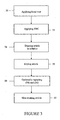
- FIG. 2 a flowchart representing another process of the present invention is shown.
- Any of the aforementioned articles may be provided and may be coated with optionally one or more of the aforementioned bond coat materials, and one or more of the aforementioned thermal barrier compounds previously discussed as indicated at boxes 30 and 32 of FIG. 2.
- the thermal barrier coating may be applied using any of the aforementioned suitable application processes described herein.
- the article may be immersed within a solution comprising a suspension containing at least a metal particulate originally present as an oxide of a metal, where the metal may be applied to the TBC using an electrophoretic deposition process as known to one of ordinary skill in the art.
- the suspension may also comprise at least one solvent, at least one pH stabilizer, optionally a dispersant and optionally a binder.
- the metal particulate concentration of the suspension may be about 0.001 weight percent solids to about 5 weight percent solids by weight of the suspension, and preferably about 0.005 weight percent solids to about 0.05 weight percent solids by weight of the suspension.
- the metal particulate may possess a diameter of about 0.02 microns to about 0.2 microns, and preferably about 0.05 microns.
- the suspension may be maintained at a temperature of about 68°F (20°C) to about 120°F (49°C), while a temperature of about 68°F (20°C), e.g., room temperature, is preferred.
- the suspension When immersing the article into the suspension, the suspension may have a pH maintained at a value below the isoelectric point of the metal particulate.
- the isoelectric point of the metal particulate may be measured using any number of processes known to one of ordinary skill in the art.
- the pH value of the suspension may be maintained at pH range of about 2 to about 7, while a pH range of about 3 to about 4.5 is preferred.
- Suitable solvents for use herein may include, but are not limited to, water, alcohols (e.g., methanol, ethanol and the like), trichloroethane, mixtures thereof, and the like.
- the pH level of the suspension may be maintained by the addition of at least one acid.
- Suitable acids for use herein may include, but are not limited to, nitric acid, hydrochloric acid, acetic acid, stearic acid, mixtures thereof, and the like.
- Suitable dispersants for use herein to prevent agglomeration and settling of the metal particulate may include, but are not limited to, pmma, ammonium stearate, and the like.
- Suitable binders may include, but are not limited to, polyvinyl alcohol and the like.
- the metal particulate may be biased with a positive DC charge within the suspension.
- the article may be biased with a negative DC charge to accelerate the suspended metal particulate towards the surface of the TBC.
- the metal particulate may then infiltrate the TBC, for example, penetrate the interstices and torturous, interconnected porosity of the TBC coating microstructures.
- Typical negative biasing voltages may range from about 50 Volts to about 2000 Volts. Although higher voltages may lead to higher deposition rates, higher voltages may also lead to hazards and raise workplace safety issues.
- the metal containing TBC coated article may be dried at a temperature of about 68°F (20°C) for about 1 hour to about 20 hours, and preferably about 3 hours to about 10 hours.
- the amount of time may be reduced to about 0.5 hours to about 5 hours, and preferably about 1 hour to about 2 hours, by raising the temperature up to about 250°F (121°C).
- boxes (34) and (36) may be repeated as often as necessary at a box 38 in order to achieve the desired metal containing TBC properties.
- the metal containing TBC coated article may also be heat treated, e.g., sintered, at a temperature of about 1950°F (1066°C) to about 2000°F (1093°C) for about 3 hours to about 4 hours, and preferably at a temperature of about 1975°F (1079°C)for about 4 hours.
- the desired metal containing TBC properties of the coated article may be characterized as at least a desired loading of metal within the interstices or tortuous, interconnected porosity of the TBC, including the desired porosity of the metal containing TBC.
- the desired loading of the metal within the TBC may be about 25% to about 100% by weight of the TBC, and preferably about 60% to about 70% by weight of the TBC.
- the desired porosity of the metal containing TBC may be no more than about 30%, and preferably no more than about 20%.
- any one of the aforementioned articles may be provided and may be coated with optionally one or more of the aforementioned bond coat materials, and one or more of the aforementioned thermal barrier compounds previously discussed as indicated at a box 50 and a box 52 of FIG. 3.
- the thermal barrier coating may be applied using any of the aforementioned suitable application processes described herein.
- the article may be immersed within an aqueous solution as indicated at a box 54 of FIG. 3.
- the aqueous solution may comprise a solvent and a metal originally present as a salt of a metal.
- the article may be dipped or immersed within the aqueous salt solution at room temperature and vacuum impregnated with the metal contained in the aqueous salt solution.
- the article When vacuum impregnating a TBC comprising a columnar structure having interstices, the article may be dipped or immersed initially at a temperature of about 68°F (20°C) to about 150°F (66°C) under a vacuum of about 10 torr (1.3 kPa, 0.19 psi) to about 100 torr (13 kPa 1.9 psi) for about 2 minutes to about 5 minutes at which point the pressure may then be adjusted to atmospheric pressure, that is, about 760 torr (101 kPa, 14.7 psi).
- a higher temperature within the range of about 68°F (20°C) to about 150°F (66°C) would be utilized if the solution exhibited a viscosity capable of impeding the infiltration of the metal within the TBC.
- the article may be dipped or immersed within the suspension at room temperature and initially under a vacuum of about 10 torr (1.3 kPa, 0.19 psi) to about 100 torr (13 kPa, 1.9 psi) for about 2 to about 10 minutes at which point the pressure may then be adjusted to atmospheric pressure.
- vacuum impregnation as well as agitating the article within the aqueous solution is utilized to draw out the air present in the interstices or porosity of the TBC in order to make room for the metal to enter.
- Suitable solvents for use in the aqueous solution include, but are not limited to, water, combinations comprising at least water, and the like.
- Suitable metals for use in the process of the present invention include, but are not limited to, lanthanum, cerium, praseodymium, neodymium, promethium, samarium, europium, gadolinium, terbium, dysprosium, holmium, erbium, thulium, ytterbium, lutelium, indium, scandium and yttrium.
- Such suitable metals may originally be present in the aqueous solution in the form of a salt of the same metals, for example, gadolinium acetate, gadolinium nitrate, zirconium acetate, zirconium nitrate, and the like.
- the metal salts disassociate to form the aforementioned metal as a metal particulate.
- the metal particulate may comprise a diameter of about 10 nanometers to about 1000 nanometers and may be present in an amount of about 25 percent to about 50 percent by volume of the aqueous solution. The size of the metal particulate allows the metal to penetrate the TBC and settle within the interstices and tortuous, interconnected porosity.
- the dipped article may be dried at a temperature of about 300°F (149°C) for an amount of time necessary to remove, that is, evaporate or burn off, the solvent at a box 56 of FIG. 3.
- boxes (54) and (56) may be repeated as often as necessary at a box 58 in order to achieve the desired metal containing TBC properties.
- the article may then be heat treated at a temperature of about 300°F (149°C) to about 750°F (399°C) at a box 60 of FIG. 3 to remove excess reagents present from the aqueous solution, for example, acetates, nitrates, and the like.
- the desired metal containing TBC properties of the coated article may be characterized as at least a desired loading of metal within the interstices or tortuous, interconnected porosity of the TBC, including the desired porosity of the metal containing TBC.
- the desired loading of the metal within the TBC may be about 25% to about 100% by weight of the TBC, and preferably about 60% to about 70% by weight of the TBC.
- the desired porosity of the metal containing TBC may be no more than about 30% by volume of the TBC, and preferably no more than about 20% by volume of the TBC.
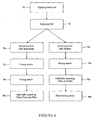
- FIG. 4 a flowchart representing another process of the present invention is shown.
- An article is provided and may be coated with an optional bond coat material layer and a thermal barrier compound at a box 70 and a box 72 of FIG. 4.
- any of the aforementioned articles may be provided and may be coated with one or more of the aforementioned optional bond coat materials and thermal barrier compounds previously discussed.
- the optional bond coat and thermal barrier coating may be applied using any of the aforementioned suitable application processes described herein.
- the TBC coated article may be sprayed with (a) the aforementioned suspension comprising the solvent, the metal originally present as an oxide of the metal, and the at least one ultra-violet curable resin, at least one dispersant and in the alternative, or in addition to, at least one surfactant as previously described, or (b) the aforementioned aqueous solution comprising the solvent and the metal originally present as a salt of the metal as previously described.
- the aforementioned suspension and aforementioned aqueous solution may each be sprayed upon at least the TBC of the TBC coated article using any processes known to one of ordinary skill in the art suitable for use herein. Suitable spraying processes include, but are not limited to, air pressure spraying, airless spraying, thermal spraying processes, air plasma spraying processes, high velocity oxygen fuel spraying processes, combinations comprising at least one of the foregoing spraying processes, and the like.
- the metal containing TBC coated article may be treated with ultra-violet light energy to cure the ultra-violet curable resin present in the metal containing TBC as previously described herein.
- the metal containing coated article may be dried to remove any excess reagents remaining in the TBC.
- the metal containing coated article may be dried under a vacuum of about 10 torr (1.3 kPa) to about 100 torr (13 kPa) at a temperature of about 68°F (20°C) to about 150°F (66°C) for an amount of time sufficient to dry the coating.
- boxes (74a), (76a) and (78a) may be repeated as often as necessary at a box 80a in order to achieve the aforementioned desired metal containing properties as described above.
- boxes (74b) and (76b) may be repeated as often as necessary at a box 80b in order to achieve the aforementioned desired metal containing properties as described above.
- the use of an aqueous solution comprising a metal salt requires an additional step to remove the excess reagents from the metal containing TBC coated article.
- the article may be heat treated at a temperature of about 300°F (149°C) to about 750°F (399°C) to remove excess reagents present from the aqueous solution, for example, acetates, nitrates, and the like.
- the resultant metal containing TBC coated article may comprise a desired loading of metal within the TBC of about 25% to about 100% by weight of the TBC, and preferably about 60% to about 70% by weight of the TBC, and in addition, or in the alternative, a desired porosity of no more than about 30% by volume of the TBC, and preferably no more than about 20% by volume of the TBC.
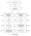
- FIG. 5 a flowchart representing yet another process of the present invention is shown.
- An article is provided and may be coated with an optional bond coat material and a thermal barrier compound to form a TBC at a box 90 and a box 92.
- any of the aforementioned articles may be provided and may be coated with one or more of the aforementioned optional bond coat materials and thermal barrier compounds previously described.
- the optional bond coat and thermal barrier coating may be applied using any of the aforementioned suitable application processes described herein.
- the TBC coated article may be brushed, or painted, with (a) the aforementioned suspension comprising the solvent, the metal originally present as an oxide of the metal, and the at least one ultra-violet curable resin, at least one dispersant and in the alternative, or in addition to, at least one surfactant as previously described, or (b) the aforementioned aqueous solution comprising the solvent and the metal originally present as a salt of the metal as previously described.
- the aforementioned suspension and aforementioned aqueous solution may each be brushed or painted upon at least the TBC of the TBC coated article using any brushing or painting processes known to one of ordinary skill in the art suitable for use herein.
- the metal containing TBC coated article may be treated with ultra-violet light energy at a box 96a to cure the ultra-violet curable resin present in the metal containing TBC as previously described herein. After curing the metal containing TBC coated article in Step 4a, the metal containing coated article may be dried to remove any excess reagents remaining in the TBC.
- the article may be dried using any of the suitable processes as previously described herein.
- the article may be dried to remove excess solvent using any of the suitable processes as previously described herein.
- steps (94a.), (96a) and (98a) may be repeated as often as necessary at a box 100a of FIG. 5 in order to achieve the aforementioned desired metal containing properties as described above.
- boxes (94b) and (96b) may be repeated as often as necessary at a box 98b of FIG. 5 in order to achieve the aforementioned desired metal containing properties as described above.
- the use of an aqueous solution comprising a metal salt requires an additional step to remove excess reagents from the metal containing TBC coated article.
- the article may be heat treated at a temperature of about 300°F (149°C) to about 750°F (399°C) to remove excess reagents present from the aqueous solution, for example, acetates, nitrates, and the like.
- the resultant metal containing TBC coated article may comprise a desired loading of metal within the TBC of about 25% to about 100% by weight of the TBC, and preferably about 60% to about 70% by weight of the TBC, and in addition, or in the alternative, a desired porosity of no more than about 30% by volume of the TBC, and preferably no more than about 20% by volume of the TBC.
- the resultant product in all of the processes of the present invention may be a metal or metal oxide containing TBC coated article.
- the article may comprise a part used in turbomachinery applications such as, but not limited to, any part having an airfoil, any part having a seal, airfoils, seals, and the like.
- TBC coatings for turbomachinery parts having seals, or seals in general are typically thicker than TBC coatings for turbomachinery parts having an airfoil, or airfoils in general.
- the metal containing TBC coatings of the coated articles of the present invention adhere to these industry standards known to one of ordinary skill in the art.
- the article may include, but is not limited to blades, vanes, stators and mid-turbine frame.
- the article may include, but is not limited to, seals, combustor panels, combustor chambers, combustor bulkhead panels, disk side plates and fuel nozzle guides.
- the metal containing TBC coatings of coated articles having an airfoil, or a coated airfoil in general, of the present invention are about 5 mils (0.13 mm) to about 15 mils (0.38 mm) thick.
- the metal containing TBC coatings of coated articles having a seal, or a coated seal in general, of the present invention are about 0.5 mils (0.013 mm) to about 50 mils (1.3 mm) thick.
- the resultant product in all of the processes of the present invention may be an article 110 coated with an optional bond coat layer 112 and at least one layer of a metal containing TBC 114 (See FIG. 6), or an article 120 coated with the at least one layer of the metal containing TBC 122 (See FIG. 7).
- the article may comprise a part used in turbomachinery applications such as, but not limited to, any part having an airfoil, any part having a seal, airfoils, seals, and the like.
- TBC coatings for turbomachinery parts having seals, or seals in general are typically thicker than TBC coatings for turbomachinery parts having an airfoil, or airfoils in general.
- the coated articles of the present invention adhere to these industry standards known to one of ordinary skill in the art.
- the metal containing TBC coating of the present invention may comprise at least the ceramic based compound, the metal comprising a particulate having a diameter of about 10 nanometers to about 1000 nanometers and present in an amount of at least about 25% by weight of the coating, and the oxide of the metal.
- the metal may be dispersed throughout the entirety of the coating, and preferably dispersed from the surface of the article to the surface of the TBC.
- the metal particulate is preferably dispersed within the interstices of the columnar structures of the TBC or the tortuous, interconnected pores of the TBC.
- the metal containing TBC coating may comprise further a porosity of no more than about 30% by volume of the TBC, and preferably no more than about 20% by volume of the TBC.
- the metal containing TBC coating of the present invention may generally comprise the metal in an amount of about 25% by weight to about 100% by weight of the TBC coating, and preferably about 60% by weight to about 70% by weight of the TBC coating, with remainder comprising the ceramic based compound and the metal oxide.
- the ceramic based compound of the TBC of the present invention may comprise any stabilized zirconate or stabilized hafnate, for example, yttria stabilized zirconia, calcia stabilized zirconia, magnesia stabilized zirconia, yttria stabilized hafnia, calcia stabilized hafnia and magnesia stabilized hafnia.
- the metal oxide may comprise an oxide of a metal such as, but not limited to, lanthanum, cerium, praseodymium, neodymium, promethium, samarium, europium, gadolinium, terbium, dysprosium, holmium, erbium, thulium, ytterbium, lutelium, indium, scandium, yttrium, combinations comprising at least one of the foregoing metals, and the like.
- a metal such as, but not limited to, lanthanum, cerium, praseodymium, neodymium, promethium, samarium, europium, gadolinium, terbium, dysprosium, holmium, erbium, thulium, ytterbium, lutelium, indium, scandium, yttrium, combinations comprising at least one of the foregoing metals, and the like.
- the metal salt may comprise a salt of a metal such as, but not limited to lanthanum, cerium, praseodymium, neodymium, promethium, samarium, europium, gadolinium, terbium, dysprosium, holmium, erbium, thulium, ytterbium, lutelium, indium, scandium, yttrium, combinations comprising at least one of the foregoing metals, and the like.
- a metal such as, but not limited to lanthanum, cerium, praseodymium, neodymium, promethium, samarium, europium, gadolinium, terbium, dysprosium, holmium, erbium, thulium, ytterbium, lutelium, indium, scandium, yttrium, combinations comprising at least one of the foregoing metals, and the like.
- the metal oxide of the TBC of the present invention is formed as a result of carrying out the processes of the present invention in an oxidizing environment.
- TBC coatings typically include metal oxides to promote their chemical stability and enhance their durability.
- the metal oxide may comprise a simple metal oxide, a binary metal oxide, a tertiary metal oxide, a poly metal oxide (quaternary, etc.), and the like.
- Binary, tertiary and poly metal oxides may form due to the presence of more than one metal initially being present, for example, more than one metal salt or metal oxide, or may form as a reaction product of the metal present in the ceramic based compound and the metal oxide or metal salt during the processes of the present invention.
- the single metal oxide may be present as the original metal oxide, the oxide of the original metal salt, the oxide of a metal of the ceramic based compound, and the like.
- the thermal barrier coating of the present invention is designed to react with at least one component of molten sand, for example, calcium magnesia alumina silicate (hereinafter referred to as "CMAS"), and form a sealant layer on or within the TBC.
- CMAS calcium magnesia alumina silicate
- a thermal barrier coating of the present invention during its use may comprise at least a reaction product of CMAS and the components of the metal containing TBC. composition of the present invention.
- the components of the metal containing TBC composition may be the aforementioned metal, metal oxide and ceramic based compound described herein including the amounts disclosed.
- the reaction product of the CMAS and metal of the TBC of the present invention may comprise further at least one reaction product as more than one reaction product may form during the useful life of the metal containing TBC of the present invention.
- a metal containing TBC comprising gadolinium, gadolinium oxide and 7YSZ may react with CMAS to form a reaction product comprising at least silicate oxyapatite comprising at least gadolinia, calcia, zirconia and silica.
- the reaction product or products form throughout the entirety of the metal containing TBC of the present invention as the metal is dispersed throughout the entirety of the TBC and the molten sand penetrates through to the coated article's surface.
- the at least one reaction product forms a sealant composition or layer throughout the metal containing TBC.
- the resultant sealant composition remains present as the metal containing TBC experiences typical wear and tear, for example, abrasion, erosion, spallation, etc., consistent with general use.
- the sealant layer reforms, remains intact and effectively takes the place of the metal containing TBC.
- the resultant sealant layer may also exhibit the desired porosity of no more than about 30% by volume of the TBC, and preferably no more than about 20% by volume of the TBC.
Abstract
Description
- The invention relates to thermal barrier coating compositions, processes for applying same and articles coated with same. More particularly, the invention relates to thermal barrier coating compositions designed to withstand molten sand infiltration, processes for applying same and articles coated with same.
- The degradation of turbomachinery parts due to sand related distress of thermal barrier coatings ("TBCs") is a concern with respect to all turbomachinery in use in the Middle East. Sand related distress is responsible for the premature spallation of TBCs and oxidation of turbomachinery and their parts. The mechanism of such sand related distress is the penetration of the TBCs by molten sand. During its useful life, sand may enter the turbomachinery, agglomerate and become molten upon the TBC surface. The molten sand penetrates the TBC and reaches the ceramic/metallic interface. The failure of the TBC occurs by a combination of molten sand attacking the thermally grown oxide at the ceramic/metallic interface as well as the reduction in strain tolerance, of the fully infiltrated TBC, to thermal cycling. Failure of the TBC occurs by spallation which exposes the part's surface to the elements, thus causing the accelerated oxidation of the turbomachinery part inconjunction with molten sand attack.
- Consequently, there exists a need for a thermal barrier coating designed to resist sand related distress.
- In accordance with the present invention, a process of coating an article broadly comprises (1) forming a layer of a ceramic based compound on an article; (2) providing a solution broadly comprising a metal particulate broadly comprising a diameter of about 10 nanometers to about 1000 nanometers and present in an amount of about 25 percent to about 50 percent by volume of the solution (3) contacting the ceramic based compound layer with the solution; and (4) drying the article.
- In accordance with the present invention, a thermal barrier coating broadly comprising a ceramic based compound; a metal oxide; and a metal broadly comprising a diameter of about 10 nanometers to about 1000 nanometers and present in an amount of at least about 25 percent by weight of the ceramic based compound, wherein the thermal barrier coating broadly comprises a porosity of no more than about 30 percent by volume of the ceramic based compound.
- In accordance with the present invention, a coated article broadly comprising an article comprising at least one surface comprising a thermal barrier coating disposed thereupon, wherein the thermal barrier coating broadly comprises a ceramic based compound; a metal oxide; and a metal in an amount of at least about 25 percent by weight of the ceramic based compound, wherein the thermal barrier coating broadly comprises a porosity of no more than about 30 percent by volume of the thermal barrier coating.
- In accordance with the present invention, a coating broadly comprising a reaction product of at least one silicate and a thermal barrier coating composition, wherein the thermal barrier coating composition broadly comprises a ceramic based compound; a metal oxide; and a metal in an amount of at least about 25 percent by weight of the ceramic based compound, wherein the thermal barrier coating comprises a porosity of no more than about 30 percent by volume of said thermal barrier coating composition.
- The details of one or more embodiments of the invention are set forth in the accompanying drawings and the description below. Other features and advantages of the invention will be apparent from the description and drawings, and from the claims.
-
- FIG. 1 is a flowchart representing one process of the present invention;
- FIG. 2 is a flowchart representing another process of the present invention of FIG. 1a;
- FIG. 3 is a flowchart representing another process of the present invention;
- FIG. 4 is a flowchart representing another process of the present invention;
- FIG. 5 is a flowchart representing another process of the present invention;
- FIG. 6 is a representation of an article coated with a bond coat and at least one layer of a metal containing thermal barrier coating of the present invention; and
- FIG. 7 is a representation of an article coated with at least one layer of a metal containing thermal barrier coating of the present invention.
- Like reference numbers and designations in the various drawings indicate like elements.
- The thermal barrier coating of the present invention is designed to react with molten sand to form a sealant layer comprising the reaction product within the thermal barrier coating. Sand generally comprises at least calcium magnesia alumina silicate (hereinafter referred to as "CMAS"), including other components such sodium, iron, potassium and the like, depending upon the geographical and geological conditions of the sand.
- As used herein, the term "solution" means a solvent and at least one solute that form a solution, a suspension, or other variation suitable for use in the present method(s), composition(s), coating(s), and coated article(s). As used herein, the term "metal" means a metal originally present as a metal of an oxide or as a metal of a salt.
- Referring now to FIG. 1, a flowchart representing one of the processes of the present invention is shown. An article may be provided and may optionally be coated with a bond coat material at a
box 12. The bond coat material may comprise a formula MCrAlY. MCrAlY refers to known metal coating systems in which M denotes nickel, cobalt, iron, platinum or mixtures thereof; Cr denotes chromium; Al denotes aluminum; and Y denotes yttrium. MCrAlY materials are often known as overlay coatings because they are applied in a predetermined composition and do not interact significantly with the substrate during the deposition process. For some non-limiting examples of MCrAlY materials seeU.S. Pat. No. 3,528,861 which describes a FeCrAlY coating as doesU.S. Pat. No. 3,542,530 . In addition,U.S. Pat. No. 3,649,225 describes a composite coating in which a layer of chromium is applied to a substrate prior to the deposition of a MCrAlY coating.U.S. Pat. No. 3,676,085 describes a CoCrAlY overlay coating whileU.S. Pat. No. 3,754,903 describes a NiCoCrAlY overlay coating having particularly high ductility.U.S. Pat. No. 4,078,922 describes a cobalt base structural alloy which derives improved oxidation resistance by virtue of the presence of a combination of hafnium and yttrium. A preferred MCrAlY bond coat composition is described inU.S. Pat. No. Re. 32,121 , which is assigned to the present Assignee and incorporated herein by reference, as having a weight percent compositional range of 5-40 Cr, 8-35 Al, 0.1-2.0 Y, 0.1-7 Si, 0.1-2.0 Hf, balance selected from the group consisting of Ni, Co and mixtures thereof. See alsoU.S. Pat. No. 4,585,481 , which is also assigned to the present Assignee and incorporated herein by reference. - The bond coat material may also comprise A1, PtAl and the like, that are often known in the art as diffusion coatings. In addition, the bond coat material may also comprise Al, PtAl, MCrAlY as described above, and the like, that are often known in the art as cathodic arc coatings.
- These bond coat materials may be applied by any method capable of producing a dense, uniform, adherent coating of the desired composition, such as, but not limited to, an overlay bond coat, diffusion bond coat, cathodic arc bond coat, etc. Such techniques may include, but are not limited to, diffusion processes (e.g., inward, outward, etc.), low pressure plasma-spray, air plasma-spray, sputtering, cathodic arc, electron beam physical vapor deposition, high velocity plasma spray techniques (e.g., HVOF, HVAF), combustion processes, wire spray techniques, laser beam cladding, electron beam cladding, etc.
- The particle size for the
bond coat 30 may be of any suitable size, and in embodiments may be between about 15 microns (0.015 mm) and about 60 microns (0.060 mm) with a mean particle size of about 25 microns (0.025 mm). Thebond coat 30 may be applied to any suitable thickness, and in embodiments may be about 5 mils (0.127 mm) to about 10 mils (0.254 mm) thick. In some embodiments, the thickness may be about 6 mils (0.152 mm) to about 7 mils (0.178 mm) thick. - After applying an optional bond coat layer to the article, the article may be coated with a thermal barrier compound to form a thermal barrier coating (hereinafter "TBC") at a
step 14 of FIG. 1. The article may comprise any part that is typically coated with a thermal barrier compound and, in particular, may comprise a part used in turbomachinery applications such as, but not limited to, any part having an airfoil, any part having a seal, airfoils, seals, and the like. The thermal barrier compound may comprise a ceramic based compound for use with turbomachinery applications as known to one of ordinary skill in the art. Representative thermal barrier compounds include, but are not limited to, any stabilized zirconate, any stabilized hafnate, combinations comprising at least one of the foregoing compounds, and the like, for example, yttria stabilized zirconia, calcia stabilized zirconia, magnesia stabilized zirconia, yttria stabilized hafnia, calcia stabilized hafnia and magnesia stabilized hafnia. Yttria stabilized zirconia is commercially available as 7YSZ®. - The thermal barrier compound may be applied to the article using any number of processes known to one of ordinary skill in the art. Suitable application processes include, but are not limited to, physical vapor deposition (e.g., electron beam), thermal spray (e.g., air plasma, high velocity oxygen fuel), sputtering, sol gel, slurry, combinations comprising at least one of the foregoing application processes, and the like. As recognized by one of ordinary skill in the art, a thermal barrier coating applied via an electron beam physical vapor deposition process forms an intercolumnar microstructure exhibiting free standing columns with interstices, that is, pores, voids, and the like, formed between the columns. Also as recognized by one of ordinary skill in the art, a thermal barrier coating applied via a thermal spray process exhibits a tortuous, interconnected porosity due to the splats and microcracks formed via the thermal spray process.
- Once the TBC is applied, the article may be immersed within a solution comprising a suspension as shown at a
box 16 of FIG. 1. The suspension may comprise a solvent, a metal originally present as an oxide of a metal, and at least one ultra-violet curable resin, at least one dispersant and in the alternative, or in addition to, at least one surfactant. When the TBC comprises columnar structures with interstices, the article may be dipped or immersed within the suspension at about 68°F (20°C) to about 150°F (66°C) and initially under a vacuum of about 10 torr (1.3 kPa, 0.19 psi) to about 100 torr (13 kPa, 1.9 psi) for about 2 minutes to about 5 minutes at which point the pressure may then be adjusted to atmospheric pressure, that is, about 760 torr (101 kPa, 14.7 psi). When the TBC comprises a tortuous, interconnected porosity, the article may be dipped or immersed within the suspension at about 68°F (20°C) to about 150°F (66°C) and initially under a vacuum of about 10 torr (1.3 kPa, 0.19 psi) to about 100 torr (13 kPa, 1.9 psi) for about 2 to about 10 minutes at which point the pressure may then be adjusted to atmospheric pressure. One of ordinary skill in the art will recognize this process is also known as vacuum impregnation. The goal is to draw out the air present in the interstices or porosity of the TBC in order to make room for the metal to enter. To further draw out the air the article may be agitated, for example, moved within the suspension, to force out any air remaining. - After immersing the TBC coated article, the coated article may be treated with ultra-violet light energy at a
box 18 of FIG. 1 to cure the ultra-violet curable resin present in the metal containing TBC. The coated article may be treated with ultra-violet light energy for about 10 second to about 60 seconds using processes known to one of ordinary skill in the art. In the alternative, when utilizing a heat curable resin, the coated article may be treated at a temperature of about 300°F (149°C) for about 20 minutes to about 60 minutes in an oven, or similar suitable apparatus, as known to one of ordinary skill in the art. - After curing the TBC coated article, the article may be dried to remove, that is, evaporate or burn off, the excess solvent, dispersant and/or resin materials at a
box 20 of FIG. 1. The article may be dried using any processes known to one of ordinary skill in the art suitable for use herein. Suitable drying processes include, but are not limited to, air drying, drying under pressure, drying under a heating element, combinations comprising at least one of the foregoing processes, and the like. The amount of time necessary to dry the article depends upon several factors and, in particular, the solvent of the suspension. For example, the metal containing TBC coated article may be dried at a temperature of about 750°F (399°C) to about 1600°F (871°C) for about 10 minutes to about 90 minutes in order to burn off the resin materials. - Suitable solvents for use in the suspension include, but are not limited to, water, alcohols, combinations comprising at least one of the foregoing solvents, and the like. Suitable dispersants may comprise organic dispersants which may evaporate and/or burn off easily during the drying step. Representative organic dispersants include, but are not limited to, polymethylmethacrylate (also known as "pmma"), polyvinyl alcohol, and the like. The aforementioned 'at least one dispersant' may be present in an amount of about 0.25% to about 3% by volume of the suspension. Suitable metals for use in the process of the present invention include, but are not limited to, lanthanum, cerium, praseodymium, neodymium, promethium, samarium, europium, gadolinium, terbium, dysprosium, holmium, erbium, thulium, ytterbium, lutelium, indium, scandium and yttrium. Such suitable metals may originally be present in the suspension in the form of an oxide of the same metals. The metal oxides may disassociate to form the aforementioned metal as a metal particulate. The metal particulate may comprise a diameter of about 10 nanometers to about 1000 nanometers and may be present in an amount of about 25 percent to about 50 percent by volume of the suspension. The size of the metal particulate allows the metal to penetrate the TBC and settle within the interstices and tortuous, interconnected porosity.
- Referring again to FIG. 1, after drying the article, boxes (16), (18) and (20) may be repeated as often as necessary at a
box 22 in order to achieve the desired metal containing TBC properties. The desired metal containing TBC properties of the coated article may be characterized as at least a desired loading of metal within the interstices or tortuous, interconnected porosity of the TBC, including the desired porosity of the metal containing TBC. The desired loading of the metal within the TBC may be about 25% to about 100% by weight of the TBC, and preferably about 60% to about 70% by weight of the TBC. The desired porosity of the metal containing TBC may be no more than about 30%, and preferably no more than about 20%. - The ultra-violet curable resin may comprise a resin, at least one of each of the following: photoinitiator, additive, modifier, monomer, and oligomer. The resin may comprise a urethane based resin that may require one or more curing steps, for example, a dual curing resin. The at least one photoinitiator may comprise a substance that initiates polymerization of the resin when exposed to ultra-violet light energy of a compatible wavelength. For a dual curing resin, two initiators may be required such that the second initiator may require heat in order to facilitate polymerization of the resin. Dual cure resins are effective when curing coatings where the ultra-violet light energy may not reach the resin material, such as in between the columnar or microcolumnar structures of the coating or at a certain depth in the coating as known to one of ordinary skill in the art. The at least one additive may comprise a filler chemical capable of enhancing one or more resin properties such as, but not limited to, flow rate, wetting, color, fluorescence and achieving tack-free surfaces. The at least one modifier may comprise a substance capable of increasing the durability, for example, impact resistance, crack resistance and the like, of the resin. The at least one monomer may comprise at least one single unit of a polymer capable of providing and/or enhancing adhesion to surface materials, for example, the adhesion of the resin to the surface of the article being coated. The at least one oligomer is recognized as the backbone of the resin and may comprise a polymer unit of about 6 monomer units to about 40 monomer units that imparts the basic properties of the ultra-violet curable resin such as, but not limited to, hardness, elongation, chemical resistance, and the like. In the alternative, the ultra-violet curable resin may be substituted with at least one heat curable resin as known to one of ordinary skill in the art.
- Referring now to FIG. 2, a flowchart representing another process of the present invention is shown. Any of the aforementioned articles may be provided and may be coated with optionally one or more of the aforementioned bond coat materials, and one or more of the aforementioned thermal barrier compounds previously discussed as indicated at
boxes - At a
box 34 of FIG. 2, the article may be immersed within a solution comprising a suspension containing at least a metal particulate originally present as an oxide of a metal, where the metal may be applied to the TBC using an electrophoretic deposition process as known to one of ordinary skill in the art. In addition to the metal particulate, the suspension may also comprise at least one solvent, at least one pH stabilizer, optionally a dispersant and optionally a binder. - The metal particulate concentration of the suspension may be about 0.001 weight percent solids to about 5 weight percent solids by weight of the suspension, and preferably about 0.005 weight percent solids to about 0.05 weight percent solids by weight of the suspension. The metal particulate may possess a diameter of about 0.02 microns to about 0.2 microns, and preferably about 0.05 microns.
- Throughout the electrophoretic deposition process, the suspension may be maintained at a temperature of about 68°F (20°C) to about 120°F (49°C), while a temperature of about 68°F (20°C), e.g., room temperature, is preferred. When immersing the article into the suspension, the suspension may have a pH maintained at a value below the isoelectric point of the metal particulate. The isoelectric point of the metal particulate may be measured using any number of processes known to one of ordinary skill in the art. The pH value of the suspension may be maintained at pH range of about 2 to about 7, while a pH range of about 3 to about 4.5 is preferred.
- Suitable solvents for use herein may include, but are not limited to, water, alcohols (e.g., methanol, ethanol and the like), trichloroethane, mixtures thereof, and the like. The pH level of the suspension may be maintained by the addition of at least one acid. Suitable acids for use herein may include, but are not limited to, nitric acid, hydrochloric acid, acetic acid, stearic acid, mixtures thereof, and the like. Suitable dispersants for use herein to prevent agglomeration and settling of the metal particulate may include, but are not limited to, pmma, ammonium stearate, and the like. Suitable binders may include, but are not limited to, polyvinyl alcohol and the like.
- The metal particulate may be biased with a positive DC charge within the suspension. At the same time, the article may be biased with a negative DC charge to accelerate the suspended metal particulate towards the surface of the TBC. The metal particulate may then infiltrate the TBC, for example, penetrate the interstices and torturous, interconnected porosity of the TBC coating microstructures. Typical negative biasing voltages may range from about 50 Volts to about 2000 Volts. Although higher voltages may lead to higher deposition rates, higher voltages may also lead to hazards and raise workplace safety issues.
- At a
box 36 of FIG. 2, the metal containing TBC coated article may be dried at a temperature of about 68°F (20°C) for about 1 hour to about 20 hours, and preferably about 3 hours to about 10 hours. The amount of time may be reduced to about 0.5 hours to about 5 hours, and preferably about 1 hour to about 2 hours, by raising the temperature up to about 250°F (121°C). After drying the article, boxes (34) and (36) may be repeated as often as necessary at abox 38 in order to achieve the desired metal containing TBC properties. - At a
box 40 of FIG. 2, the metal containing TBC coated article may also be heat treated, e.g., sintered, at a temperature of about 1950°F (1066°C) to about 2000°F (1093°C) for about 3 hours to about 4 hours, and preferably at a temperature of about 1975°F (1079°C)for about 4 hours. The desired metal containing TBC properties of the coated article may be characterized as at least a desired loading of metal within the interstices or tortuous, interconnected porosity of the TBC, including the desired porosity of the metal containing TBC. The desired loading of the metal within the TBC may be about 25% to about 100% by weight of the TBC, and preferably about 60% to about 70% by weight of the TBC. The desired porosity of the metal containing TBC may be no more than about 30%, and preferably no more than about 20%. - Referring now to FIG. 3, a flowchart representing another process of the present invention is shown. Again, any one of the aforementioned articles may be provided and may be coated with optionally one or more of the aforementioned bond coat materials, and one or more of the aforementioned thermal barrier compounds previously discussed as indicated at a
box 50 and abox 52 of FIG. 3. The thermal barrier coating may be applied using any of the aforementioned suitable application processes described herein. - Once the TBC is applied, the article may be immersed within an aqueous solution as indicated at a
box 54 of FIG. 3. The aqueous solution may comprise a solvent and a metal originally present as a salt of a metal. The article may be dipped or immersed within the aqueous salt solution at room temperature and vacuum impregnated with the metal contained in the aqueous salt solution. When vacuum impregnating a TBC comprising a columnar structure having interstices, the article may be dipped or immersed initially at a temperature of about 68°F (20°C) to about 150°F (66°C) under a vacuum of about 10 torr (1.3 kPa, 0.19 psi) to about 100 torr (13 kPa 1.9 psi) for about 2 minutes to about 5 minutes at which point the pressure may then be adjusted to atmospheric pressure, that is, about 760 torr (101 kPa, 14.7 psi). A higher temperature within the range of about 68°F (20°C) to about 150°F (66°C) would be utilized if the solution exhibited a viscosity capable of impeding the infiltration of the metal within the TBC. When the TBC comprises a tortuous, interconnected porosity, the article may be dipped or immersed within the suspension at room temperature and initially under a vacuum of about 10 torr (1.3 kPa, 0.19 psi) to about 100 torr (13 kPa, 1.9 psi) for about 2 to about 10 minutes at which point the pressure may then be adjusted to atmospheric pressure. Again, vacuum impregnation as well as agitating the article within the aqueous solution is utilized to draw out the air present in the interstices or porosity of the TBC in order to make room for the metal to enter. - Suitable solvents for use in the aqueous solution include, but are not limited to, water, combinations comprising at least water, and the like. Suitable metals for use in the process of the present invention include, but are not limited to, lanthanum, cerium, praseodymium, neodymium, promethium, samarium, europium, gadolinium, terbium, dysprosium, holmium, erbium, thulium, ytterbium, lutelium, indium, scandium and yttrium. Such suitable metals may originally be present in the aqueous solution in the form of a salt of the same metals, for example, gadolinium acetate, gadolinium nitrate, zirconium acetate, zirconium nitrate, and the like. The metal salts disassociate to form the aforementioned metal as a metal particulate. The metal particulate may comprise a diameter of about 10 nanometers to about 1000 nanometers and may be present in an amount of about 25 percent to about 50 percent by volume of the aqueous solution. The size of the metal particulate allows the metal to penetrate the TBC and settle within the interstices and tortuous, interconnected porosity.
- After dipping or immersing the TBC coated article, the dipped article may be dried at a temperature of about 300°F (149°C) for an amount of time necessary to remove, that is, evaporate or burn off, the solvent at a
box 56 of FIG. 3. After removing the solvent, boxes (54) and (56) may be repeated as often as necessary at abox 58 in order to achieve the desired metal containing TBC properties. The article may then be heat treated at a temperature of about 300°F (149°C) to about 750°F (399°C) at abox 60 of FIG. 3 to remove excess reagents present from the aqueous solution, for example, acetates, nitrates, and the like. The desired metal containing TBC properties of the coated article may be characterized as at least a desired loading of metal within the interstices or tortuous, interconnected porosity of the TBC, including the desired porosity of the metal containing TBC. The desired loading of the metal within the TBC may be about 25% to about 100% by weight of the TBC, and preferably about 60% to about 70% by weight of the TBC. The desired porosity of the metal containing TBC may be no more than about 30% by volume of the TBC, and preferably no more than about 20% by volume of the TBC. - Referring now to FIG. 4, a flowchart representing another process of the present invention is shown. An article is provided and may be coated with an optional bond coat material layer and a thermal barrier compound at a
box 70 and abox 72 of FIG. 4. Again, any of the aforementioned articles may be provided and may be coated with one or more of the aforementioned optional bond coat materials and thermal barrier compounds previously discussed. The optional bond coat and thermal barrier coating may be applied using any of the aforementioned suitable application processes described herein. - Once the TBC is applied, the TBC coated article may be sprayed with (a) the aforementioned suspension comprising the solvent, the metal originally present as an oxide of the metal, and the at least one ultra-violet curable resin, at least one dispersant and in the alternative, or in addition to, at least one surfactant as previously described, or (b) the aforementioned aqueous solution comprising the solvent and the metal originally present as a salt of the metal as previously described. At
boxes - After spraying the TBC coated article, the metal containing TBC coated article may be treated with ultra-violet light energy to cure the ultra-violet curable resin present in the metal containing TBC as previously described herein. After curing the TBC coated article at a
box 76a, the metal containing coated article may be dried to remove any excess reagents remaining in the TBC. For example, atboxes - When utilizing the aforementioned suspension, boxes (74a), (76a) and (78a) may be repeated as often as necessary at a
box 80a in order to achieve the aforementioned desired metal containing properties as described above. When utilizing the aforementioned aqueous solution, boxes (74b) and (76b) may be repeated as often as necessary at abox 80b in order to achieve the aforementioned desired metal containing properties as described above. - As described earlier, the use of an aqueous solution comprising a metal salt requires an additional step to remove the excess reagents from the metal containing TBC coated article. At a
box 80b of FIG. 4, the article may be heat treated at a temperature of about 300°F (149°C) to about 750°F (399°C) to remove excess reagents present from the aqueous solution, for example, acetates, nitrates, and the like. - In forming coated articles using the processes shown in FIG. 4, the resultant metal containing TBC coated article may comprise a desired loading of metal within the TBC of about 25% to about 100% by weight of the TBC, and preferably about 60% to about 70% by weight of the TBC, and in addition, or in the alternative, a desired porosity of no more than about 30% by volume of the TBC, and preferably no more than about 20% by volume of the TBC.
- Referring now to FIG. 5, a flowchart representing yet another process of the present invention is shown. An article is provided and may be coated with an optional bond coat material and a thermal barrier compound to form a TBC at a
box 90 and abox 92. Again, any of the aforementioned articles may be provided and may be coated with one or more of the aforementioned optional bond coat materials and thermal barrier compounds previously described. The optional bond coat and thermal barrier coating may be applied using any of the aforementioned suitable application processes described herein. - Once the TBC is applied, the TBC coated article may be brushed, or painted, with (a) the aforementioned suspension comprising the solvent, the metal originally present as an oxide of the metal, and the at least one ultra-violet curable resin, at least one dispersant and in the alternative, or in addition to, at least one surfactant as previously described, or (b) the aforementioned aqueous solution comprising the solvent and the metal originally present as a salt of the metal as previously described. At
boxes - After brushing or painting the TBC coated article at
box 94a, the metal containing TBC coated article may be treated with ultra-violet light energy at abox 96a to cure the ultra-violet curable resin present in the metal containing TBC as previously described herein. After curing the metal containing TBC coated article in Step 4a, the metal containing coated article may be dried to remove any excess reagents remaining in the TBC. - At a
box 98a of FIG. 5, the article may be dried using any of the suitable processes as previously described herein. At abox 96b of FIG. 5, the article may be dried to remove excess solvent using any of the suitable processes as previously described herein. - When utilizing the aforementioned suspension, steps (94a.), (96a) and (98a) may be repeated as often as necessary at a
box 100a of FIG. 5 in order to achieve the aforementioned desired metal containing properties as described above. When utilizing the aforementioned aqueous solution, boxes (94b) and (96b) may be repeated as often as necessary at abox 98b of FIG. 5 in order to achieve the aforementioned desired metal containing properties as described above. - As described earlier, the use of an aqueous solution comprising a metal salt requires an additional step to remove excess reagents from the metal containing TBC coated article. In
step 100b of FIG. 5, the article may be heat treated at a temperature of about 300°F (149°C) to about 750°F (399°C) to remove excess reagents present from the aqueous solution, for example, acetates, nitrates, and the like. - In forming coated articles using the processes shown in FIG. 5, the resultant metal containing TBC coated article may comprise a desired loading of metal within the TBC of about 25% to about 100% by weight of the TBC, and preferably about 60% to about 70% by weight of the TBC, and in addition, or in the alternative, a desired porosity of no more than about 30% by volume of the TBC, and preferably no more than about 20% by volume of the TBC.
- The resultant product in all of the processes of the present invention may be a metal or metal oxide containing TBC coated article. As described earlier, the article may comprise a part used in turbomachinery applications such as, but not limited to, any part having an airfoil, any part having a seal, airfoils, seals, and the like. As known to one of ordinary skill in the art, TBC coatings for turbomachinery parts having seals, or seals in general, are typically thicker than TBC coatings for turbomachinery parts having an airfoil, or airfoils in general. Likewise, the metal containing TBC coatings of the coated articles of the present invention adhere to these industry standards known to one of ordinary skill in the art.
- For example, the article may include, but is not limited to blades, vanes, stators and mid-turbine frame. And, in yet another example, the article may include, but is not limited to, seals, combustor panels, combustor chambers, combustor bulkhead panels, disk side plates and fuel nozzle guides.
- Generally, the metal containing TBC coatings of coated articles having an airfoil, or a coated airfoil in general, of the present invention are about 5 mils (0.13 mm) to about 15 mils (0.38 mm) thick. And, generally, the metal containing TBC coatings of coated articles having a seal, or a coated seal in general, of the present invention are about 0.5 mils (0.013 mm) to about 50 mils (1.3 mm) thick. These ranges of TBC coating thicknesses for such coated articles may be broadened or narrowed depending upon the particular application of the article as will be recognized and understood in the future by one of ordinary skill in the art.
- Referring now to FIGS. 6 and 7, the resultant product in all of the processes of the present invention may be an
article 110 coated with an optionalbond coat layer 112 and at least one layer of a metal containing TBC 114 (See FIG. 6), or anarticle 120 coated with the at least one layer of the metal containing TBC 122 (See FIG. 7). As described earlier, the article may comprise a part used in turbomachinery applications such as, but not limited to, any part having an airfoil, any part having a seal, airfoils, seals, and the like. As known to one of ordinary skill in the art, TBC coatings for turbomachinery parts having seals, or seals in general, are typically thicker than TBC coatings for turbomachinery parts having an airfoil, or airfoils in general. Likewise, the coated articles of the present invention adhere to these industry standards known to one of ordinary skill in the art. - The metal containing TBC coating of the present invention may comprise at least the ceramic based compound, the metal comprising a particulate having a diameter of about 10 nanometers to about 1000 nanometers and present in an amount of at least about 25% by weight of the coating, and the oxide of the metal. The metal may be dispersed throughout the entirety of the coating, and preferably dispersed from the surface of the article to the surface of the TBC. The metal particulate is preferably dispersed within the interstices of the columnar structures of the TBC or the tortuous, interconnected pores of the TBC. As a result, the metal containing TBC coating may comprise further a porosity of no more than about 30% by volume of the TBC, and preferably no more than about 20% by volume of the TBC.
- The metal containing TBC coating of the present invention may generally comprise the metal in an amount of about 25% by weight to about 100% by weight of the TBC coating, and preferably about 60% by weight to about 70% by weight of the TBC coating, with remainder comprising the ceramic based compound and the metal oxide.
- The ceramic based compound of the TBC of the present invention may comprise any stabilized zirconate or stabilized hafnate, for example, yttria stabilized zirconia, calcia stabilized zirconia, magnesia stabilized zirconia, yttria stabilized hafnia, calcia stabilized hafnia and magnesia stabilized hafnia. The metal oxide may comprise an oxide of a metal such as, but not limited to, lanthanum, cerium, praseodymium, neodymium, promethium, samarium, europium, gadolinium, terbium, dysprosium, holmium, erbium, thulium, ytterbium, lutelium, indium, scandium, yttrium, combinations comprising at least one of the foregoing metals, and the like. The metal salt may comprise a salt of a metal such as, but not limited to lanthanum, cerium, praseodymium, neodymium, promethium, samarium, europium, gadolinium, terbium, dysprosium, holmium, erbium, thulium, ytterbium, lutelium, indium, scandium, yttrium, combinations comprising at least one of the foregoing metals, and the like.
- The metal oxide of the TBC of the present invention is formed as a result of carrying out the processes of the present invention in an oxidizing environment. As known to one of ordinary skill in the art, TBC coatings typically include metal oxides to promote their chemical stability and enhance their durability. The metal oxide may comprise a simple metal oxide, a binary metal oxide, a tertiary metal oxide, a poly metal oxide (quaternary, etc.), and the like. Binary, tertiary and poly metal oxides may form due to the presence of more than one metal initially being present, for example, more than one metal salt or metal oxide, or may form as a reaction product of the metal present in the ceramic based compound and the metal oxide or metal salt during the processes of the present invention. Likewise, the single metal oxide may be present as the original metal oxide, the oxide of the original metal salt, the oxide of a metal of the ceramic based compound, and the like.
- The thermal barrier coating of the present invention is designed to react with at least one component of molten sand, for example, calcium magnesia alumina silicate (hereinafter referred to as "CMAS"), and form a sealant layer on or within the TBC. As a result, a thermal barrier coating of the present invention during its use may comprise at least a reaction product of CMAS and the components of the metal containing TBC. composition of the present invention.
- The components of the metal containing TBC composition may be the aforementioned metal, metal oxide and ceramic based compound described herein including the amounts disclosed. The reaction product of the CMAS and metal of the TBC of the present invention may comprise further at least one reaction product as more than one reaction product may form during the useful life of the metal containing TBC of the present invention. For example, a metal containing TBC comprising gadolinium, gadolinium oxide and 7YSZ may react with CMAS to form a reaction product comprising at least silicate oxyapatite comprising at least gadolinia, calcia, zirconia and silica.
- The reaction product or products form throughout the entirety of the metal containing TBC of the present invention as the metal is dispersed throughout the entirety of the TBC and the molten sand penetrates through to the coated article's surface. The at least one reaction product forms a sealant composition or layer throughout the metal containing TBC. The resultant sealant composition remains present as the metal containing TBC experiences typical wear and tear, for example, abrasion, erosion, spallation, etc., consistent with general use. Thus, as the metal containing TBC wears during its useful life, the sealant layer reforms, remains intact and effectively takes the place of the metal containing TBC. The resultant sealant layer may also exhibit the desired porosity of no more than about 30% by volume of the TBC, and preferably no more than about 20% by volume of the TBC.
- One or more embodiments of the present invention have been described. Nevertheless, it will be understood that various modifications may be made without departing from the scope of the invention. Accordingly, other embodiments are within the scope of the following claims.
Claims (38)
- A process of coating an article, comprising:(1) forming a layer of a ceramic based compound on an article;(2) providing a solution comprising a metal particulate having a diameter of about 10 nanometers to about 1000 nanometers and present in an amount of about 25 percent to about 50 percent by volume of said solution;(3) contacting said ceramic based compound layer with said solution; and(4) drying said article.
- The process of claim 1, further comprising (5) optionally repeating steps (3) and (4).
- The process of claim 1 or 2, further comprising optionally forming a layer of a bond coat material on said article prior to forming said ceramic based compound layer and forming said ceramic based compound layer upon said bond coat layer.
- The process of claim 1, 2 or 3, wherein forming comprises forming said ceramic based compound layer using a process selected from the group consisting of physical vapor deposition, thermal spraying, sputtering, sol gel and slurry.
- The process of claim 4, wherein said physical vapor deposition process is an electron beam physical vapor deposition process.
- The process of claim 4, wherein said thermal spraying process is a high velocity oxygen fuel thermal spraying process or air plasma thermal spraying process.
- The process of any preceding claim, wherein contacting comprises dipping said article into said solution comprising a suspension of said metal originally present as a metal oxide and at least one of each of a dispersant, an ultra-violet curable resin and optionally a surfactant.
- The process of claim 7, wherein dipping comprises dipping said article into said solution comprising said metal oxide comprising at least one metal selected from the group consisting of lanthanum, cerium, praseodymium, neodymium, promethium, samarium, europium, gadolinium, terbium, dysprosium, holmium, erbium, thulium, ytterbium, lutelium, indium, scandium, yttrium, zirconium, hafnium, titanium, and mixtures thereof.
- The process of claim 7 or 8, wherein dipping comprises dipping initially said article at a pressure of about 10 torr (1.3 kPa) to about 100 torr (13 kPa) for about 2 minutes to about 5 minutes.
- The process of claim 9, further comprising optionally repeating steps (2) and (3), wherein optionally repeating steps (2) and (3) comprises dipping said article at about 14.7 pounds per square inch (101 kPa).
- The process of any of claims 7 to 10, wherein contacting comprises dipping said article at about 60°F (16°C) to about 65°F (18°C).
- The process of any of claims 7 to 11, further comprising the steps of:curing said article using ultra-violet light energy for about 10 seconds to about 60 seconds; andheat treating said article at a temperature of about 750°F (399°C) to about 1600°F (871°C) for about 10 minutes to about 90 minutes.
- The process of any of claims 7 to 11, further comprising the steps of:curing said article at a temperature of about 300°F (149°C) for about 20 minutes to about 60 minutes; andheat treating said article at a temperature of about 750°F (399°C) to about 1600°F (871°C) for about 10 to about 90 minutes.
- The process of any of claims 1 to 6, wherein contacting comprises infiltrating said ceramic based compound layer with said solution comprising a metal originally in the form of a metal salt.
- The process of claim 14, wherein infiltrating comprises infiltrating said ceramic based compound layer with said solution comprising said metal salt comprising at least one metal selected from the group consisting of lanthanum, cerium, praseodymium, neodymium, promethium, samarium, europium, gadolinium, terbium, dysprosium, holmium, erbium, thulium, ytterbium, lutelium, indium, scandium, yttrium, zirconium, hafnium, titanium, and mixtures thereof.
- The process of claim 14 or 15, wherein drying comprises dewatering said ceramic based compound layer at a temperature of about 300°F (149°C).
- The process of claim 16, further comprising heat treating said article after step (4) at a temperature of about 300°F (149°C) to about 750°F (399°C).
- The process of any of claims 1 to 6, wherein contacting comprises spraying said article with said solution comprising said metal originally present in the form of a metal salt.
- The process of claim 18, wherein spraying comprises spraying said article with said solution comprising said metal salt comprising at least one metal selected from the group consisting of lanthanum, cerium, praseodymium, neodymium, promethium, samarium, europium, gadolinium, terbium, dysprosium, holmium, erbium, thulium, ytterbium, lutelium, indium, scandium, yttrium, zirconium, hafnium, titanium, and mixtures thereof.
- The process of claim 18 or 19, wherein spraying comprises air spraying or thermally spraying said coated article with said solution.
- The process of claim 18, 19 or 20 wherein spraying comprises spraying initially said coated article with said solution at a pressure of about 10 torr (1.3 kPa) to about 100 torr (13 kPa) for about 2 minutes to about 10 minutes.
- The process of any of claims 1 to 6, wherein contacting comprises brushing said article with said solution comprising said metal originally present in the form of a metal salt.
- The process of claim 22, wherein brushing comprises brushing said article with said solution comprising said metal salt comprising at least one metal selected from the group consisting of lanthanum, cerium, praseodymium, neodymium, promethium, samarium, europium, gadolinium, terbium, dysprosium, holmium, erbium, thulium, ytterbium, lutelium, indium, scandium, yttrium, zirconium, hafnium, titanium, and mixtures thereof.
- The process of any of claims 1 to 6, wherein contacting comprises the steps of:immersing said article into said solution comprising a suspension of said metal originally present as a metal oxide and at least one of each of a dispersant, a binder and an acid;negatively biasing said article;positively biasing said suspension;infiltrating said ceramic based compound with said metal; andsintering said article at a temperature of about 1950°F (1066°C) to about 2000°F (1093°C) for about 3 hours to about 4 hours.
- The process of claim 24, wherein drying said coated article comprises drying said article at a temperature of about 68°F (20°C) for about 1 hour to about 20 hours.
- The process of claim 24, wherein drying said coated article comprises drying said article at a temperature of up to about 250°F (121°C) for about 0.5 hours to about 5 hours.
- A coated article, comprising:an article (110; 120) comprising at least one surface having a thermal barrier coating (114; 122) disposed thereupon,wherein said thermal barrier coating (114; 122) comprises:a ceramic based compound;a metal oxide; anda metal in an amount of at least about 25 percent by weight of said ceramic based compound,wherein the thermal barrier coating (114; 122) comprises a porosity of no more than about 30 percent by volume of said thermal barrier coating (114; 122).
- The coated article of claim 27, further comprising a bond coat layer (112) disposed between said at least one surface and said thermal barrier coating (114).
- The coated article of claim 28, wherein said bond coat (112) layer comprises a bond coat material comprising a formula MCrAlY, wherein said M is a metal selected from the group consisting of nickel, cobalt, iron and mixtures thereof.
- The coated article of claim 28, wherein said bond coat layer (112) comprises a bond coat material selected from the group consisting of aluminum, platinum, and mixtures thereof.
- The coated article of claim 28, wherein said bond coat layer (112) comprises a bond coat material selected from the group consisting of aluminum, platinum and MCrAlY, wherein said M of said MCrAlY is a metal selected from the group consisting of nickel, cobalt, and iron, and mixtures thereof.
- The coated article of any of claims 27 to 31, wherein said ceramic based compound is selected from the group consisting of yttria stabilized zirconia, calcia stabilized zirconia, magnesia stabilized zirconia, yttria stabilized hafnia, calcia stabilized hafnia and magnesia stabilized hafnia.
- The coated article of any of claims 27 to 32, wherein said metal oxide is an oxide of at least one metal selected from the group consisting of lanthanum, cerium, praseodymium, neodymium, promethium, samarium, europium, gadolinium, terbium, dysprosium, holmium, erbium, thulium, ytterbium, lutelium, indium, scandium, yttrium, zirconium, hafnium, titanium, and mixtures thereof.
- The coated article of any of claims 27 to 33, wherein said metal is selected from the group consisting of lanthanum, cerium, praseodymium, neodymium, promethium, samarium, europium, gadolinium, terbium, dysprosium, holmium, erbium, thulium, ytterbium, lutelium, indium, scandium, yttrium, zirconium, hafnium, titanium, and mixtures thereof.
- The coated article of any of claims 27 to 34, wherein said article (110; 120) is selected from the group consisting of blades, vanes, stators and mid-turbine frame.
- The coated article of claim 35, wherein said thermal barrier coating (114; 122) comprises a thickness of about 5 mils (0.13 mm) to about 15 mils (0.38 mm).
- The coated article of any of claims 27 to 34, wherein said article (110; 120) is selected from the group consisting of seals, combustor panels, combustor chambers, combustor bulkhead shields, disk side plates and fuel nozzle guides.
- The coated article of claim 37, wherein said thermal barrier coating (114; 122) comprises a thickness of about 0.5 mils (0.013 mm) to about 50 mils (1.3 mm).
Applications Claiming Priority (1)
| Application Number | Priority Date | Filing Date | Title |
|---|---|---|---|
| US11/328,894 US7579087B2 (en) | 2006-01-10 | 2006-01-10 | Thermal barrier coating compositions, processes for applying same and articles coated with same |
Publications (2)
| Publication Number | Publication Date |
|---|---|
| EP1806423A1 true EP1806423A1 (en) | 2007-07-11 |
| EP1806423B1 EP1806423B1 (en) | 2011-03-02 |
Family
ID=37865450
Family Applications (1)
| Application Number | Title | Priority Date | Filing Date |
|---|---|---|---|
| EP07250088A Active EP1806423B1 (en) | 2006-01-10 | 2007-01-10 | A process for Applying a thermal Barrier Coating |
Country Status (7)
| Country | Link |
|---|---|
| US (2) | US7579087B2 (en) |
| EP (1) | EP1806423B1 (en) |
| JP (1) | JP2007185654A (en) |
| KR (1) | KR20070075269A (en) |
| CN (1) | CN101033545A (en) |
| DE (1) | DE602007012778D1 (en) |
| SG (1) | SG134217A1 (en) |
Cited By (7)
| Publication number | Priority date | Publication date | Assignee | Title |
|---|---|---|---|---|
| US8221825B2 (en) | 2009-03-30 | 2012-07-17 | Alstom Technology Ltd. | Comprehensive method for local application and local repair of thermal barrier coatings |
| EP1820879B1 (en) * | 2006-01-20 | 2012-08-08 | United Technologies Corporation | Durable reactive thermal barrier coatings |
| WO2015073175A1 (en) | 2013-11-14 | 2015-05-21 | United Technologies Corporation | Ceramic coated articles and manufacture methods |
| WO2015116300A2 (en) | 2013-12-06 | 2015-08-06 | United Technologies Corporation | Calcium-magnesium alumino-silicate (cmas) resistant thermal barrier coatings, systems, and methods of production thereof |
| EP3002348A1 (en) * | 2014-09-30 | 2016-04-06 | United Technologies Corporation | Multi-phase pre-reacted thermal barrier coatings and process therefor |
| EP3115133A1 (en) * | 2015-07-10 | 2017-01-11 | General Electric Company | Coating process and coated component |
| EP4215638A4 (en) * | 2020-12-28 | 2023-07-26 | Mitsubishi Heavy Industries Aero Engines, Ltd. | Method for implementing thermal barrier coating and heat-resistant member |
Families Citing this family (83)
| Publication number | Priority date | Publication date | Assignee | Title |
|---|---|---|---|---|
| US9101978B2 (en) | 2002-12-08 | 2015-08-11 | Baker Hughes Incorporated | Nanomatrix powder metal compact |
| US9079246B2 (en) | 2009-12-08 | 2015-07-14 | Baker Hughes Incorporated | Method of making a nanomatrix powder metal compact |
| US8297364B2 (en) | 2009-12-08 | 2012-10-30 | Baker Hughes Incorporated | Telescopic unit with dissolvable barrier |
| US9682425B2 (en) | 2009-12-08 | 2017-06-20 | Baker Hughes Incorporated | Coated metallic powder and method of making the same |
| US8327931B2 (en) * | 2009-12-08 | 2012-12-11 | Baker Hughes Incorporated | Multi-component disappearing tripping ball and method for making the same |
| US8403037B2 (en) * | 2009-12-08 | 2013-03-26 | Baker Hughes Incorporated | Dissolvable tool and method |
| US9109429B2 (en) | 2002-12-08 | 2015-08-18 | Baker Hughes Incorporated | Engineered powder compact composite material |
| US7875370B2 (en) * | 2006-08-18 | 2011-01-25 | United Technologies Corporation | Thermal barrier coating with a plasma spray top layer |
| SG155778A1 (en) * | 2008-03-10 | 2009-10-29 | Turbine Overhaul Services Pte | Method for diffusion bonding metallic components with nanoparticle foil |
| EP2143819A1 (en) * | 2008-07-11 | 2010-01-13 | Siemens Aktiengesellschaft | Coating method and corrosion protection coating for turbine components |
| US8343591B2 (en) * | 2008-10-24 | 2013-01-01 | United Technologies Corporation | Method for use with a coating process |
| US8273470B2 (en) * | 2008-12-19 | 2012-09-25 | General Electric Company | Environmental barrier coatings providing CMAS mitigation capability for ceramic substrate components |
| US20100154422A1 (en) * | 2008-12-19 | 2010-06-24 | Glen Harold Kirby | Cmas mitigation compositions, environmental barrier coatings comprising the same, and ceramic components comprising the same |
| US8343589B2 (en) | 2008-12-19 | 2013-01-01 | General Electric Company | Methods for making environmental barrier coatings and ceramic components having CMAS mitigation capability |
| US8658291B2 (en) * | 2008-12-19 | 2014-02-25 | General Electric Company | CMAS mitigation compositions, environmental barrier coatings comprising the same, and ceramic components comprising the same |
| US8039113B2 (en) * | 2008-12-19 | 2011-10-18 | General Electric Company | Environmental barrier coatings providing CMAS mitigation capability for ceramic substrate components |
| US8658255B2 (en) * | 2008-12-19 | 2014-02-25 | General Electric Company | Methods for making environmental barrier coatings and ceramic components having CMAS mitigation capability |
| US8119247B2 (en) * | 2008-12-19 | 2012-02-21 | General Electric Company | Environmental barrier coatings providing CMAS mitigation capability for ceramic substrate components |
| US20100227146A1 (en) * | 2009-03-06 | 2010-09-09 | Larose Joel | Thermal barrier coating with lower thermal conductivity |
| US20110086163A1 (en) | 2009-10-13 | 2011-04-14 | Walbar Inc. | Method for producing a crack-free abradable coating with enhanced adhesion |
| US20110086177A1 (en) | 2009-10-14 | 2011-04-14 | WALBAR INC. Peabody Industrial Center | Thermal spray method for producing vertically segmented thermal barrier coatings |
| US8573295B2 (en) | 2010-11-16 | 2013-11-05 | Baker Hughes Incorporated | Plug and method of unplugging a seat |
| US10240419B2 (en) | 2009-12-08 | 2019-03-26 | Baker Hughes, A Ge Company, Llc | Downhole flow inhibition tool and method of unplugging a seat |
| US8528633B2 (en) | 2009-12-08 | 2013-09-10 | Baker Hughes Incorporated | Dissolvable tool and method |
| US8425651B2 (en) | 2010-07-30 | 2013-04-23 | Baker Hughes Incorporated | Nanomatrix metal composite |
| US9243475B2 (en) | 2009-12-08 | 2016-01-26 | Baker Hughes Incorporated | Extruded powder metal compact |
| US9227243B2 (en) | 2009-12-08 | 2016-01-05 | Baker Hughes Incorporated | Method of making a powder metal compact |
| US9127515B2 (en) | 2010-10-27 | 2015-09-08 | Baker Hughes Incorporated | Nanomatrix carbon composite |
| US20110151219A1 (en) * | 2009-12-21 | 2011-06-23 | Bangalore Nagaraj | Coating Systems for Protection of Substrates Exposed to Hot and Harsh Environments and Coated Articles |
| US8481117B2 (en) * | 2010-03-08 | 2013-07-09 | United Technologies Corporation | Method for applying a thermal barrier coating |
| US20110223317A1 (en) * | 2010-03-12 | 2011-09-15 | United Technologies Corporation | Direct thermal stabilization for coating application |
| FR2957358B1 (en) * | 2010-03-12 | 2012-04-13 | Snecma | METHOD FOR MANUFACTURING THERMAL BARRIER PROTECTION AND MULTILAYER COATING FOR FORMING A THERMAL BARRIER |
| US9187815B2 (en) * | 2010-03-12 | 2015-11-17 | United Technologies Corporation | Thermal stabilization of coating material vapor stream |
| US8776884B2 (en) | 2010-08-09 | 2014-07-15 | Baker Hughes Incorporated | Formation treatment system and method |
| US9090955B2 (en) | 2010-10-27 | 2015-07-28 | Baker Hughes Incorporated | Nanomatrix powder metal composite |
| US8631876B2 (en) | 2011-04-28 | 2014-01-21 | Baker Hughes Incorporated | Method of making and using a functionally gradient composite tool |
| US9080098B2 (en) | 2011-04-28 | 2015-07-14 | Baker Hughes Incorporated | Functionally gradient composite article |
| US9139928B2 (en) | 2011-06-17 | 2015-09-22 | Baker Hughes Incorporated | Corrodible downhole article and method of removing the article from downhole environment |
| US9707739B2 (en) | 2011-07-22 | 2017-07-18 | Baker Hughes Incorporated | Intermetallic metallic composite, method of manufacture thereof and articles comprising the same |
| US9643250B2 (en) | 2011-07-29 | 2017-05-09 | Baker Hughes Incorporated | Method of controlling the corrosion rate of alloy particles, alloy particle with controlled corrosion rate, and articles comprising the particle |
| US9833838B2 (en) | 2011-07-29 | 2017-12-05 | Baker Hughes, A Ge Company, Llc | Method of controlling the corrosion rate of alloy particles, alloy particle with controlled corrosion rate, and articles comprising the particle |
| US9033055B2 (en) | 2011-08-17 | 2015-05-19 | Baker Hughes Incorporated | Selectively degradable passage restriction and method |
| US9896966B2 (en) | 2011-08-29 | 2018-02-20 | United Technologies Corporation | Tie rod for a gas turbine engine |
| US9109269B2 (en) | 2011-08-30 | 2015-08-18 | Baker Hughes Incorporated | Magnesium alloy powder metal compact |
| US9090956B2 (en) | 2011-08-30 | 2015-07-28 | Baker Hughes Incorporated | Aluminum alloy powder metal compact |
| US9856547B2 (en) | 2011-08-30 | 2018-01-02 | Bakers Hughes, A Ge Company, Llc | Nanostructured powder metal compact |
| US9643144B2 (en) | 2011-09-02 | 2017-05-09 | Baker Hughes Incorporated | Method to generate and disperse nanostructures in a composite material |
| US9187990B2 (en) | 2011-09-03 | 2015-11-17 | Baker Hughes Incorporated | Method of using a degradable shaped charge and perforating gun system |
| US9347119B2 (en) | 2011-09-03 | 2016-05-24 | Baker Hughes Incorporated | Degradable high shock impedance material |
| US9133695B2 (en) | 2011-09-03 | 2015-09-15 | Baker Hughes Incorporated | Degradable shaped charge and perforating gun system |
| US9284812B2 (en) | 2011-11-21 | 2016-03-15 | Baker Hughes Incorporated | System for increasing swelling efficiency |
| US9010416B2 (en) | 2012-01-25 | 2015-04-21 | Baker Hughes Incorporated | Tubular anchoring system and a seat for use in the same |
| US9068428B2 (en) | 2012-02-13 | 2015-06-30 | Baker Hughes Incorporated | Selectively corrodible downhole article and method of use |
| US9605508B2 (en) | 2012-05-08 | 2017-03-28 | Baker Hughes Incorporated | Disintegrable and conformable metallic seal, and method of making the same |
| US9816339B2 (en) | 2013-09-03 | 2017-11-14 | Baker Hughes, A Ge Company, Llc | Plug reception assembly and method of reducing restriction in a borehole |
| WO2015061306A1 (en) | 2013-10-25 | 2015-04-30 | United Technologies Corporation | Plasma spraying system with adjustable coating medium nozzle |
| CN103614710B (en) * | 2013-11-29 | 2015-12-02 | 重庆市中工新材料有限公司 | A kind of steel alloy surface C e-Nd binary rare-earth colloidal sol method for composite ceramic treatment |
| US20150174837A1 (en) * | 2013-12-19 | 2015-06-25 | General Electric Company | Turbine component patch delivery system |
| US11167343B2 (en) | 2014-02-21 | 2021-11-09 | Terves, Llc | Galvanically-active in situ formed particles for controlled rate dissolving tools |
| CA2936851A1 (en) | 2014-02-21 | 2015-08-27 | Terves, Inc. | Fluid activated disintegrating metal system |
| CN104451528B (en) * | 2014-12-05 | 2017-01-18 | 航天材料及工艺研究所 | High-radiation coating applied to outer wall surface of rhenium-iridium engine combustion chamber |
| US9869188B2 (en) * | 2014-12-12 | 2018-01-16 | General Electric Company | Articles for high temperature service and method for making |
| US9910026B2 (en) | 2015-01-21 | 2018-03-06 | Baker Hughes, A Ge Company, Llc | High temperature tracers for downhole detection of produced water |
| US10378303B2 (en) | 2015-03-05 | 2019-08-13 | Baker Hughes, A Ge Company, Llc | Downhole tool and method of forming the same |
| US10221637B2 (en) | 2015-08-11 | 2019-03-05 | Baker Hughes, A Ge Company, Llc | Methods of manufacturing dissolvable tools via liquid-solid state molding |
| US9970305B2 (en) * | 2015-09-18 | 2018-05-15 | General Electric Company | Treatment process, oxide-forming treatment composition, and treated component |
| US10201831B2 (en) | 2015-12-09 | 2019-02-12 | General Electric Company | Coating inspection method |
| US10016810B2 (en) | 2015-12-14 | 2018-07-10 | Baker Hughes, A Ge Company, Llc | Methods of manufacturing degradable tools using a galvanic carrier and tools manufactured thereof |
| DE102016203246A1 (en) * | 2016-02-29 | 2017-08-31 | Siemens Aktiengesellschaft | Coating with temperature sensor as well as coated component |
| US10822966B2 (en) | 2016-05-09 | 2020-11-03 | General Electric Company | Thermal barrier system with bond coat barrier |
| US10384978B2 (en) * | 2016-08-22 | 2019-08-20 | General Electric Company | Thermal barrier coating repair compositions and methods of use thereof |
| US10822696B2 (en) | 2016-12-14 | 2020-11-03 | General Electric Company | Article with thermal barrier coating and method for making |
| CN107032831B (en) * | 2017-03-29 | 2018-02-23 | 北京航空航天大学 | A kind of Rare Earth T/EBC ceramic bases combinational environment barrier coating and preparation method thereof |
| CN107032798A (en) * | 2017-05-31 | 2017-08-11 | 清华大学 | A kind of preparation method of the porous ceramic film material based on photocureable rapid shaping |
| CN107032797B (en) * | 2017-05-31 | 2020-07-24 | 清华大学 | Ceramic-based interlayer composite material based on photocuring molding and preparation method thereof |
| CA3012511A1 (en) | 2017-07-27 | 2019-01-27 | Terves Inc. | Degradable metal matrix composite |
| US20190194812A1 (en) * | 2017-12-21 | 2019-06-27 | GM Global Technology Operations LLC | Gap-filling sealing layer of thermal barrier coating |
| US11668198B2 (en) | 2018-08-03 | 2023-06-06 | Raytheon Technologies Corporation | Fiber-reinforced self-healing environmental barrier coating |
| US11505506B2 (en) | 2018-08-16 | 2022-11-22 | Raytheon Technologies Corporation | Self-healing environmental barrier coating |
| US11535571B2 (en) | 2018-08-16 | 2022-12-27 | Raytheon Technologies Corporation | Environmental barrier coating for enhanced resistance to attack by molten silicate deposits |
| US10934220B2 (en) | 2018-08-16 | 2021-03-02 | Raytheon Technologies Corporation | Chemical and topological surface modification to enhance coating adhesion and compatibility |
| FR3090695B1 (en) | 2018-12-21 | 2020-12-04 | Safran | hot conforming core coating |
| SG10202010783RA (en) | 2019-11-06 | 2021-06-29 | Gen Electric | Restoration coating system and method |
Citations (7)
| Publication number | Priority date | Publication date | Assignee | Title |
|---|---|---|---|---|
| US5660885A (en) * | 1995-04-03 | 1997-08-26 | General Electric Company | Protection of thermal barrier coating by a sacrificial surface coating |
| EP1088908A2 (en) * | 1999-10-01 | 2001-04-04 | General Electric Company | A method for smoothing the surface of a protective coating |
| US6465090B1 (en) * | 1995-11-30 | 2002-10-15 | General Electric Company | Protective coating for thermal barrier coatings and coating method therefor |
| EP1428902A1 (en) * | 2002-12-12 | 2004-06-16 | General Electric Company | Thermal barrier coating protected by infiltrated alumina and method for preparing same |
| US6770325B2 (en) * | 2000-05-19 | 2004-08-03 | The University Of British Columbia | Process for making chemically bonded composite hydroxide ceramics |
| EP1484427A2 (en) * | 2003-06-06 | 2004-12-08 | General Electric Company | Top coating system for industrial turbine nozzle airfoils and other hot gas path components and related method |
| WO2006137890A2 (en) * | 2004-09-27 | 2006-12-28 | Honeywell International Inc. | Method of forming stabilized plasma-sprayed thermal barrier coatings |
Family Cites Families (22)
| Publication number | Priority date | Publication date | Assignee | Title |
|---|---|---|---|---|
| US3542530A (en) | 1968-05-23 | 1970-11-24 | United Aircraft Corp | Nickel or cobalt base with a coating containing iron chromium and aluminum |
| US3528861A (en) | 1968-05-23 | 1970-09-15 | United Aircraft Corp | Method for coating the superalloys |
| US3649225A (en) | 1969-11-17 | 1972-03-14 | United Aircraft Corp | Composite coating for the superalloys |
| US3754903A (en) | 1970-09-15 | 1973-08-28 | United Aircraft Corp | High temperature oxidation resistant coating alloy |
| US3676085A (en) | 1971-02-18 | 1972-07-11 | United Aircraft Corp | Cobalt base coating for the superalloys |
| GB1562790A (en) * | 1975-11-27 | 1980-03-19 | British Gas Corp | Quench chambers for coal gasification plant |
| US4078922A (en) | 1975-12-08 | 1978-03-14 | United Technologies Corporation | Oxidation resistant cobalt base alloy |
| US4585481A (en) | 1981-08-05 | 1986-04-29 | United Technologies Corporation | Overlays coating for superalloys |
| US4948764A (en) | 1986-09-16 | 1990-08-14 | Lanxide Technology Company, Lp | Production of ceramic and ceramic-metal composite articles with surface coatings |
| US5516595A (en) | 1986-09-16 | 1996-05-14 | Lanxide Technology Company, Lp | Production of ceramic and ceramic-metal composite articles with surface coatings |
| US5419971A (en) * | 1993-03-03 | 1995-05-30 | General Electric Company | Enhanced thermal barrier coating system |
| WO1996031293A1 (en) * | 1995-04-03 | 1996-10-10 | General Electric Company | Method and composite for protection of thermal barrier coating by a sacrificial surface coating |
| RU2196846C2 (en) * | 1995-11-13 | 2003-01-20 | Дзе Юниверсити оф Коннектикут | Nanostructural raw materials for thermic deposition |
| JPH1088368A (en) | 1996-09-19 | 1998-04-07 | Toshiba Corp | Thermal insulation coating member and its production |
| WO2000068330A1 (en) * | 1999-05-10 | 2000-11-16 | Shunichi Haruyama | Inorganic-organic film and starting liquid composition therefor and method for preparation thereof, and applications and method for preparing them |
| US6730413B2 (en) * | 2001-07-31 | 2004-05-04 | General Electric Company | Thermal barrier coating |
| EP1327703A1 (en) * | 2002-01-15 | 2003-07-16 | Siemens Aktiengesellschaft | Coating system with a porous layer |
| EP1365039A1 (en) * | 2002-05-24 | 2003-11-26 | ALSTOM (Switzerland) Ltd | Process of masking colling holes of a gas turbine component |
| US6960395B2 (en) * | 2003-12-30 | 2005-11-01 | General Electric Company | Ceramic compositions useful for thermal barrier coatings having reduced thermal conductivity |
| US20050202270A1 (en) * | 2004-03-10 | 2005-09-15 | Skoog Andrew J. | Powder coating of gas turbine engine components |
| US20060110609A1 (en) * | 2004-11-19 | 2006-05-25 | Eaton Harry E | Protective coatings |
| US20070160859A1 (en) | 2006-01-06 | 2007-07-12 | General Electric Company | Layered thermal barrier coatings containing lanthanide series oxides for improved resistance to CMAS degradation |
-
2006
- 2006-01-10 US US11/328,894 patent/US7579087B2/en active Active
- 2006-12-12 SG SG200608678-9A patent/SG134217A1/en unknown
- 2006-12-26 JP JP2006348887A patent/JP2007185654A/en active Pending
- 2006-12-27 KR KR1020060135238A patent/KR20070075269A/en not_active Application Discontinuation
-
2007
- 2007-01-10 EP EP07250088A patent/EP1806423B1/en active Active
- 2007-01-10 DE DE602007012778T patent/DE602007012778D1/en active Active
- 2007-01-10 CN CNA2007100022496A patent/CN101033545A/en active Pending
-
2009
- 2009-08-24 US US12/546,526 patent/US8529999B2/en active Active
Patent Citations (7)
| Publication number | Priority date | Publication date | Assignee | Title |
|---|---|---|---|---|
| US5660885A (en) * | 1995-04-03 | 1997-08-26 | General Electric Company | Protection of thermal barrier coating by a sacrificial surface coating |
| US6465090B1 (en) * | 1995-11-30 | 2002-10-15 | General Electric Company | Protective coating for thermal barrier coatings and coating method therefor |
| EP1088908A2 (en) * | 1999-10-01 | 2001-04-04 | General Electric Company | A method for smoothing the surface of a protective coating |
| US6770325B2 (en) * | 2000-05-19 | 2004-08-03 | The University Of British Columbia | Process for making chemically bonded composite hydroxide ceramics |
| EP1428902A1 (en) * | 2002-12-12 | 2004-06-16 | General Electric Company | Thermal barrier coating protected by infiltrated alumina and method for preparing same |
| EP1484427A2 (en) * | 2003-06-06 | 2004-12-08 | General Electric Company | Top coating system for industrial turbine nozzle airfoils and other hot gas path components and related method |
| WO2006137890A2 (en) * | 2004-09-27 | 2006-12-28 | Honeywell International Inc. | Method of forming stabilized plasma-sprayed thermal barrier coatings |
Cited By (13)
| Publication number | Priority date | Publication date | Assignee | Title |
|---|---|---|---|---|
| EP1820879B1 (en) * | 2006-01-20 | 2012-08-08 | United Technologies Corporation | Durable reactive thermal barrier coatings |
| US8343587B2 (en) | 2006-01-20 | 2013-01-01 | United Technologies Corporation | Process of forming durable reactive thermal barrier coatings |
| US8221825B2 (en) | 2009-03-30 | 2012-07-17 | Alstom Technology Ltd. | Comprehensive method for local application and local repair of thermal barrier coatings |
| EP3068924A4 (en) * | 2013-11-14 | 2017-08-02 | United Technologies Corporation | Ceramic coated articles and manufacture methods |
| WO2015073175A1 (en) | 2013-11-14 | 2015-05-21 | United Technologies Corporation | Ceramic coated articles and manufacture methods |
| EP3916121A1 (en) * | 2013-11-14 | 2021-12-01 | Raytheon Technologies Corporation | Ceramic coated articles and manufacture methods |
| US10322976B2 (en) | 2013-12-06 | 2019-06-18 | United Technologies Corporation | Calcium-magnesium alumino-silicate (CMAS) resistant thermal barrier coatings, systems, and methods of production thereof |
| EP3077563A4 (en) * | 2013-12-06 | 2017-07-05 | United Technologies Corporation | Calcium-magnesium alumino-silicate (cmas) resistant thermal barrier coatings, systems, and methods of production thereof |
| US10934217B2 (en) | 2013-12-06 | 2021-03-02 | Raytheon Technologies Corporation | Calcium-magnesium alumino-silicate (CMAS) resistant thermal barrier coatings, systems, and methods of production thereof |
| WO2015116300A2 (en) | 2013-12-06 | 2015-08-06 | United Technologies Corporation | Calcium-magnesium alumino-silicate (cmas) resistant thermal barrier coatings, systems, and methods of production thereof |
| EP3002348A1 (en) * | 2014-09-30 | 2016-04-06 | United Technologies Corporation | Multi-phase pre-reacted thermal barrier coatings and process therefor |
| EP3115133A1 (en) * | 2015-07-10 | 2017-01-11 | General Electric Company | Coating process and coated component |
| EP4215638A4 (en) * | 2020-12-28 | 2023-07-26 | Mitsubishi Heavy Industries Aero Engines, Ltd. | Method for implementing thermal barrier coating and heat-resistant member |
Also Published As
| Publication number | Publication date |
|---|---|
| JP2007185654A (en) | 2007-07-26 |
| KR20070075269A (en) | 2007-07-18 |
| US7579087B2 (en) | 2009-08-25 |
| US20090308733A1 (en) | 2009-12-17 |
| SG134217A1 (en) | 2007-08-29 |
| EP1806423B1 (en) | 2011-03-02 |
| US8529999B2 (en) | 2013-09-10 |
| US20080113217A1 (en) | 2008-05-15 |
| CN101033545A (en) | 2007-09-12 |
| DE602007012778D1 (en) | 2011-04-14 |
Similar Documents
| Publication | Publication Date | Title |
|---|---|---|
| EP1806423B1 (en) | A process for Applying a thermal Barrier Coating | |
| US7455913B2 (en) | Thermal barrier coating compositions, processes for applying same and articles coated with same | |
| US7622195B2 (en) | Thermal barrier coating compositions, processes for applying same and articles coated with same | |
| US9624583B2 (en) | Slurry-based coating techniques for smoothing surface imperfections | |
| US8343587B2 (en) | Process of forming durable reactive thermal barrier coatings | |
| JP5067775B2 (en) | Process for producing corrosion-resistant EBC bond coats and the like for silicon-containing substrates | |
| EP2208805B1 (en) | Strain tolerant thermal barrier coating system | |
| EP2287130B1 (en) | Methods of making environmental barrier coatings for high temperature ceramic components using sintering aids | |
| EP1811060A2 (en) | CMAS resistant thermal barrier coating | |
| EP1889949B1 (en) | Sodium containing thermal barrier coating | |
| EP2113586A2 (en) | Low cost non-line-of-sight portective coatings | |
| EP2947173B1 (en) | Calcium magnesium aluminosilicate (cmas) resistant thermal barrier coating and coating process therefor | |
| EP2000557B1 (en) | Erosion barrier for thermal barrier coatings | |
| EP3002348B1 (en) | Process for coating gas turbine engine components comprising multi-phase pre-reacted thermal barrier coatings and coated gas turbine engine components |
Legal Events
| Date | Code | Title | Description |
|---|---|---|---|
| PUAI | Public reference made under article 153(3) epc to a published international application that has entered the european phase |
Free format text: ORIGINAL CODE: 0009012 |
|
| AK | Designated contracting states |
Kind code of ref document: A1 Designated state(s): AT BE BG CH CY CZ DE DK EE ES FI FR GB GR HU IE IS IT LI LT LU LV MC NL PL PT RO SE SI SK TR |
|
| AX | Request for extension of the european patent |
Extension state: AL BA HR MK RS |
|
| 17P | Request for examination filed |
Effective date: 20080109 |
|
| 17Q | First examination report despatched |
Effective date: 20080211 |
|
| AKX | Designation fees paid |
Designated state(s): CH DE GB LI NL |
|
| GRAP | Despatch of communication of intention to grant a patent |
Free format text: ORIGINAL CODE: EPIDOSNIGR1 |
|
| RTI1 | Title (correction) |
Free format text: A PROCESS FOR APPLYING A THERMAL BARRIER COATING |
|
| GRAA | (expected) grant |
Free format text: ORIGINAL CODE: 0009210 |
|
| GRAS | Grant fee paid |
Free format text: ORIGINAL CODE: EPIDOSNIGR3 |
|
| AK | Designated contracting states |
Kind code of ref document: B1 Designated state(s): CH DE GB LI NL |
|
| REG | Reference to a national code |
Ref country code: GB Ref legal event code: FG4D |
|
| REG | Reference to a national code |
Ref country code: CH Ref legal event code: EP |
|
| REF | Corresponds to: |
Ref document number: 602007012778 Country of ref document: DE Date of ref document: 20110414 Kind code of ref document: P |
|
| REG | Reference to a national code |
Ref country code: DE Ref legal event code: R096 Ref document number: 602007012778 Country of ref document: DE Effective date: 20110414 |
|
| REG | Reference to a national code |
Ref country code: NL Ref legal event code: VDEP Effective date: 20110302 |
|
| PG25 | Lapsed in a contracting state [announced via postgrant information from national office to epo] |
Ref country code: NL Free format text: LAPSE BECAUSE OF FAILURE TO SUBMIT A TRANSLATION OF THE DESCRIPTION OR TO PAY THE FEE WITHIN THE PRESCRIBED TIME-LIMIT Effective date: 20110302 |
|
| PLBE | No opposition filed within time limit |
Free format text: ORIGINAL CODE: 0009261 |
|
| STAA | Information on the status of an ep patent application or granted ep patent |
Free format text: STATUS: NO OPPOSITION FILED WITHIN TIME LIMIT |
|
| 26N | No opposition filed |
Effective date: 20111205 |
|
| REG | Reference to a national code |
Ref country code: DE Ref legal event code: R097 Ref document number: 602007012778 Country of ref document: DE Effective date: 20111205 |
|
| REG | Reference to a national code |
Ref country code: CH Ref legal event code: PL |
|
| PG25 | Lapsed in a contracting state [announced via postgrant information from national office to epo] |
Ref country code: CH Free format text: LAPSE BECAUSE OF NON-PAYMENT OF DUE FEES Effective date: 20120131 Ref country code: LI Free format text: LAPSE BECAUSE OF NON-PAYMENT OF DUE FEES Effective date: 20120131 |
|
| REG | Reference to a national code |
Ref country code: DE Ref legal event code: R082 Ref document number: 602007012778 Country of ref document: DE Representative=s name: SCHMITT-NILSON SCHRAUD WAIBEL WOHLFROM PATENTA, DE |
|
| REG | Reference to a national code |
Ref country code: DE Ref legal event code: R082 Ref document number: 602007012778 Country of ref document: DE Representative=s name: SCHMITT-NILSON SCHRAUD WAIBEL WOHLFROM PATENTA, DE Ref country code: DE Ref legal event code: R081 Ref document number: 602007012778 Country of ref document: DE Owner name: UNITED TECHNOLOGIES CORP. (N.D.GES.D. STAATES , US Free format text: FORMER OWNER: UNITED TECHNOLOGIES CORPORATION, HARTFORD, CONN., US |
|
| REG | Reference to a national code |
Ref country code: DE Ref legal event code: R081 Ref document number: 602007012778 Country of ref document: DE Owner name: RAYTHEON TECHNOLOGIES CORPORATION (N.D.GES.D.S, US Free format text: FORMER OWNER: UNITED TECHNOLOGIES CORP. (N.D.GES.D. STAATES DELAWARE), FARMINGTON, CONN., US |
|
| PGFP | Annual fee paid to national office [announced via postgrant information from national office to epo] |
Ref country code: DE Payment date: 20221220 Year of fee payment: 17 |
|
| P01 | Opt-out of the competence of the unified patent court (upc) registered |
Effective date: 20230519 |
|
| PGFP | Annual fee paid to national office [announced via postgrant information from national office to epo] |
Ref country code: GB Payment date: 20231219 Year of fee payment: 18 |