EP1808124B1 - Mapping of complex fractionated atrial electrogram - Google Patents
Mapping of complex fractionated atrial electrogram Download PDFInfo
- Publication number
- EP1808124B1 EP1808124B1 EP07250104A EP07250104A EP1808124B1 EP 1808124 B1 EP1808124 B1 EP 1808124B1 EP 07250104 A EP07250104 A EP 07250104A EP 07250104 A EP07250104 A EP 07250104A EP 1808124 B1 EP1808124 B1 EP 1808124B1
- Authority
- EP
- European Patent Office
- Prior art keywords
- heart
- cfae
- catheter
- complex fractionated
- points
- Prior art date
- Legal status (The legal status is an assumption and is not a legal conclusion. Google has not performed a legal analysis and makes no representation as to the accuracy of the status listed.)
- Active
Links
- 238000013507 mapping Methods 0.000 title claims description 18
- 230000001746 atrial effect Effects 0.000 title description 5
- 230000000694 effects Effects 0.000 claims description 14
- 238000004590 computer program Methods 0.000 claims description 2
- 210000005242 cardiac chamber Anatomy 0.000 abstract description 12
- 238000000034 method Methods 0.000 description 26
- 238000002679 ablation Methods 0.000 description 13
- 206010003658 Atrial Fibrillation Diseases 0.000 description 10
- 230000004913 activation Effects 0.000 description 7
- 230000000747 cardiac effect Effects 0.000 description 7
- 238000001514 detection method Methods 0.000 description 7
- 210000005246 left atrium Anatomy 0.000 description 7
- 230000002159 abnormal effect Effects 0.000 description 5
- 238000010586 diagram Methods 0.000 description 5
- 230000006870 function Effects 0.000 description 5
- 210000005003 heart tissue Anatomy 0.000 description 5
- 230000033001 locomotion Effects 0.000 description 5
- 239000011159 matrix material Substances 0.000 description 5
- 206010003119 arrhythmia Diseases 0.000 description 4
- 238000005259 measurement Methods 0.000 description 4
- 230000008569 process Effects 0.000 description 4
- 238000012545 processing Methods 0.000 description 4
- 230000002035 prolonged effect Effects 0.000 description 4
- 210000005245 right atrium Anatomy 0.000 description 4
- 230000001225 therapeutic effect Effects 0.000 description 4
- 210000001519 tissue Anatomy 0.000 description 4
- 238000004422 calculation algorithm Methods 0.000 description 3
- 238000004364 calculation method Methods 0.000 description 3
- 210000000038 chest Anatomy 0.000 description 3
- 230000003750 conditioning effect Effects 0.000 description 3
- 230000005672 electromagnetic field Effects 0.000 description 3
- 210000002837 heart atrium Anatomy 0.000 description 3
- 238000002955 isolation Methods 0.000 description 3
- 230000004044 response Effects 0.000 description 3
- 238000013459 approach Methods 0.000 description 2
- 230000008901 benefit Effects 0.000 description 2
- 230000005540 biological transmission Effects 0.000 description 2
- 238000002847 impedance measurement Methods 0.000 description 2
- 230000033764 rhythmic process Effects 0.000 description 2
- 239000000758 substrate Substances 0.000 description 2
- 230000002792 vascular Effects 0.000 description 2
- 206010001497 Agitation Diseases 0.000 description 1
- 230000009471 action Effects 0.000 description 1
- 230000003321 amplification Effects 0.000 description 1
- 238000004458 analytical method Methods 0.000 description 1
- 230000006793 arrhythmia Effects 0.000 description 1
- 230000003126 arrythmogenic effect Effects 0.000 description 1
- 238000013153 catheter ablation Methods 0.000 description 1
- 238000006243 chemical reaction Methods 0.000 description 1
- 238000004040 coloring Methods 0.000 description 1
- 238000004891 communication Methods 0.000 description 1
- 230000001143 conditioned effect Effects 0.000 description 1
- 238000010276 construction Methods 0.000 description 1
- 230000002950 deficient Effects 0.000 description 1
- 230000001419 dependent effect Effects 0.000 description 1
- 238000003745 diagnosis Methods 0.000 description 1
- 238000006073 displacement reaction Methods 0.000 description 1
- 238000011156 evaluation Methods 0.000 description 1
- 230000001747 exhibiting effect Effects 0.000 description 1
- 238000001914 filtration Methods 0.000 description 1
- 238000010438 heat treatment Methods 0.000 description 1
- 230000001939 inductive effect Effects 0.000 description 1
- 238000003780 insertion Methods 0.000 description 1
- 230000037431 insertion Effects 0.000 description 1
- 230000003902 lesion Effects 0.000 description 1
- 238000012986 modification Methods 0.000 description 1
- 230000004048 modification Effects 0.000 description 1
- 210000004165 myocardium Anatomy 0.000 description 1
- 238000003199 nucleic acid amplification method Methods 0.000 description 1
- 230000003287 optical effect Effects 0.000 description 1
- 230000037361 pathway Effects 0.000 description 1
- 230000002085 persistent effect Effects 0.000 description 1
- 238000007674 radiofrequency ablation Methods 0.000 description 1
- 230000029058 respiratory gaseous exchange Effects 0.000 description 1
- 239000000523 sample Substances 0.000 description 1
- 210000002186 septum of brain Anatomy 0.000 description 1
- 230000001954 sterilising effect Effects 0.000 description 1
- 238000004659 sterilization and disinfection Methods 0.000 description 1
- 230000002459 sustained effect Effects 0.000 description 1
- 238000002604 ultrasonography Methods 0.000 description 1
- 230000000007 visual effect Effects 0.000 description 1
Images


Classifications
-
- A—HUMAN NECESSITIES
- A61—MEDICAL OR VETERINARY SCIENCE; HYGIENE
- A61B—DIAGNOSIS; SURGERY; IDENTIFICATION
- A61B5/00—Measuring for diagnostic purposes; Identification of persons
- A61B5/24—Detecting, measuring or recording bioelectric or biomagnetic signals of the body or parts thereof
- A61B5/25—Bioelectric electrodes therefor
- A61B5/279—Bioelectric electrodes therefor specially adapted for particular uses
- A61B5/28—Bioelectric electrodes therefor specially adapted for particular uses for electrocardiography [ECG]
- A61B5/283—Invasive
- A61B5/287—Holders for multiple electrodes, e.g. electrode catheters for electrophysiological study [EPS]
-
- A—HUMAN NECESSITIES
- A61—MEDICAL OR VETERINARY SCIENCE; HYGIENE
- A61B—DIAGNOSIS; SURGERY; IDENTIFICATION
- A61B5/00—Measuring for diagnostic purposes; Identification of persons
- A61B5/05—Detecting, measuring or recording for diagnosis by means of electric currents or magnetic fields; Measuring using microwaves or radio waves
-
- A—HUMAN NECESSITIES
- A61—MEDICAL OR VETERINARY SCIENCE; HYGIENE
- A61B—DIAGNOSIS; SURGERY; IDENTIFICATION
- A61B5/00—Measuring for diagnostic purposes; Identification of persons
- A61B5/24—Detecting, measuring or recording bioelectric or biomagnetic signals of the body or parts thereof
- A61B5/316—Modalities, i.e. specific diagnostic methods
- A61B5/318—Heart-related electrical modalities, e.g. electrocardiography [ECG]
- A61B5/346—Analysis of electrocardiograms
- A61B5/349—Detecting specific parameters of the electrocardiograph cycle
-
- A—HUMAN NECESSITIES
- A61—MEDICAL OR VETERINARY SCIENCE; HYGIENE
- A61B—DIAGNOSIS; SURGERY; IDENTIFICATION
- A61B18/00—Surgical instruments, devices or methods for transferring non-mechanical forms of energy to or from the body
- A61B18/04—Surgical instruments, devices or methods for transferring non-mechanical forms of energy to or from the body by heating
- A61B18/12—Surgical instruments, devices or methods for transferring non-mechanical forms of energy to or from the body by heating by passing a current through the tissue to be heated, e.g. high-frequency current
- A61B18/14—Probes or electrodes therefor
- A61B18/1492—Probes or electrodes therefor having a flexible, catheter-like structure, e.g. for heart ablation
-
- A—HUMAN NECESSITIES
- A61—MEDICAL OR VETERINARY SCIENCE; HYGIENE
- A61B—DIAGNOSIS; SURGERY; IDENTIFICATION
- A61B18/00—Surgical instruments, devices or methods for transferring non-mechanical forms of energy to or from the body
- A61B2018/00636—Sensing and controlling the application of energy
- A61B2018/00773—Sensed parameters
- A61B2018/00839—Bioelectrical parameters, e.g. ECG, EEG
Definitions
- This invention relates to the diagnosis and treatment of cardiac arrhythmias. More particularly, this invention relates to obtaining information indicative of regional electrical activity in the cardiac chambers, and to the identification and treatment of arrhythmogenic areas.
- Cardiac arrhythmias such as atrial fibrillation are an important cause of morbidity and death.
- location and electrical activity is typically initially measured on about 10 to about 20 points on the interior surface of the heart. These data points are then generally sufficient to generate a preliminary reconstruction or map of the cardiac surface.
- the preliminary map is often combined with data taken at additional points in order to generate a more comprehensive map of the heart's electrical activity. Indeed, in clinical settings, it is not uncommon to accumulate data at 100 or more sites to generate a detailed, comprehensive map of heart chamber electrical activity. The generated detailed map may then serve as the basis for deciding on a therapeutic course of action, for example, tissue ablation, to alter the propagation of the heart's electrical activity and to restore normal heart rhythm.
- Catheters containing position sensors may be used to determine the trajectory of points on the cardiac surface. These trajectories may be used to infer motion characteristics such as the contractility of the tissue. As disclosed in U.S. Patent No. 5,738,096 , issued to Ben Haim, maps depicting such motion characteristics may be constructed when the trajectory information is sampled at a sufficient number of points in the heart.
- Electrode activity at a point in the heart is typically measured by advancing a catheter containing an electrical sensor at or near its distal tip to that point in the heart, contacting the tissue with the sensor and acquiring data at that point.
- One drawback with mapping a cardiac chamber using a catheter containing only a single, distal tip electrode is the long period of time required to accumulate data on a point-by-point basis over the requisite number of points required for a detailed map of the chamber as a whole. Accordingly, multiple-electrode catheters have been developed to simultaneously measure electrical activity at multiple points in the heart chamber.
- Atrial electrograms during sustained atrial fibrillation have three distinct patterns: single potential, double potential and a complex fractionated atrial electrograms (CFAE's).
- the CFAE areas represent the atrial fibrillation substrate sites and become important target sites for ablation. By ablating areas having persistent CFAE's, atrial fibrillation may be eliminated and even rendered non-inducible.
- Atrial fibrillation may be successfully treated by ablating sites exhibiting a complex fractionated atrial electrogram.
- the authors identified areas of CFAE during atrial fibrillation, and then applied radiofrequency ablation to these areas. As a result of the ablation, the atrial fibrillation was resolved in the large majority of the cases.
- CFAE was mapped manually, i.e., the actual local electrogram was read out during atrial fibrillation, and a human operator read the electrogram to identify sites of CFAE. The operator marked these sites on an electrical activation map as points of reference for subsequent ablation.
- aspects of the present invention provide specialized system software and systems for electroanatomical mapping systems, in order to map areas of CFAE automatically within cardiac chambers.
- a method developed for this purpose analyzes the electrogram signal to count the number of CFAE complexes whose amplitude and peak-to-peak intervals meet certain criteria.
- Fig. 1 is a pictorial illustration of a system for detecting areas of abnormal electrical activity and performing ablative procedures on a heart of a living subject;
- Fig. 2 is a diagram of an embodiment of a catheter for use in the system shown in Fig. 1 ;
- Fig. 3 is a diagram depicting the distal end of a catheter in contact with the endocardial surface of the right atrium of a heart;
- Fig. 4 is a group of exemplary electrograms illustrating CFAE's, which can be automatically identified according to a disclosed embodiment of the invention
- Fig. 5 is a block diagram illustrating a subsystem of the system shown in Fig. 1 , in accordance with a disclosed embodiment of the invention
- Fig. 6 is a functional map of the left atrium in which a color scale indicates the average cycle length between identified CFAE's;
- Fig. 7 is a functional map of the left atrium in which a color scale indicates the shortest interval between identified CFAE's for each acquired point;
- Fig. 8 is an interval confidence map of the left atrium, in accordance with the invention.
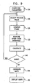
- Fig. 9 is a flow chart illustrating a method of CFAE detection, in accordance with a disclosed embodiment of the invention.
- Fig. 10 is a screen display illustrating a tracing, in which peaks and peak-to-peak intervals identified during the performance of the method shown in Fig. 9 have been annotated;
- Fig. 11 is a screen display of a point list of data was acquired in accordance with a disclosed embodiment of the invention.
- Fig. 12 is an illustration of a system for detecting areas of abnormal electrical activity and performing ablative procedures on a heart of a living subject.
- Fig. 13 is a simplified sectional view of a thorax showing a torso vest and electrodes.
- Software programming code which embodies aspects of the present invention, is typically maintained in permanent storage, such as a computer readable medium.
- a computer readable medium In a client-server environment, such software programming code may be stored on a client or a server.
- the software programming code may be embodied on any of a variety of known media for use with a data processing system. This includes, but is not limited to, magnetic and optical storage devices such as disk drives, magnetic tape, compact discs (CD's), digital video discs (DVD's), and computer instruction signals embodied in a transmission medium with or without a carrier wave upon which the signals are modulated.
- the transmission medium may include a communications network, such as the Internet.
- the invention may be embodied in computer software, the functions necessary to implement the invention may alternatively be embodied in part or in whole using hardware components such as application-specific integrated circuits or other hardware, or some combination of hardware components and software.
- Fig. 1 is a pictorial illustration of a system 10 for detecting areas of abnormal electrical activity and performing ablative procedures on a heart 12 of a living subject 21.
- the system comprises a probe, typically a catheter 14, which is percutaneously inserted by an operator 16, who is typically a physician, through the patient's vascular system into a chamber or vascular structure of the heart.
- the operator 16 brings the catheter's distal tip 18 into contact with the heart wall at a target site that is to be evaluated.
- Electrical activation maps are then prepared, according to the methods disclosed in the above-noted U.S. Patent Nos. 6,226,542 , and 6,301,496 , and in commonly assigned U.S. Patent No. 6,892,091 .
- Areas determined to be abnormal by evaluation of the electrical activation maps can be ablated application of thermal energy, e.g., by passage of radiofrequency electrical current through wires in the catheter to one or more electrodes at the distal tip 18, which apply the radiofrequency energy to the myocardium.
- the energy is absorbed in the tissue, heating it to a point (typically about 50°C) at which it permanently loses its electrical excitability.
- this procedure creates non-conducting lesions in the cardiac tissue, which disrupt the abnormal electrical pathway causing the arrhythmia.
- other known methods of applying ablative energy can be used, e.g., ultrasound energy, as disclosed in U.S. Patent Application Publication No. 2004/0102769 .
- the principles of the invention are disclosed with respect to atrial complex fractionated electrograms, but can be applied to all heart chambers, to epicardial as well as endocardial approaches, and to mapping in sinus rhythm, and when many different cardiac arrhythmias are present.
- the catheter 14 typically comprises a handle 20, having suitable controls on the handle to enable the operator 16 to steer, position and orient the distal end of the catheter as desired to the ablation.
- the distal portion of the catheter 14 contains position sensors (not shown) that provide signals to a positioning processor 22, located in a console 24.
- the catheter 14, may be adapted, mutatis mutandis, from the ablation catheter described in commonly assigned U.S. Patent No. 6,669,692 .
- the console 24 typically contains an ablation power generator 43.
- the positioning processor 22 is an element of a positioning subsystem 26 that measures location and orientation coordinates of the catheter 14.
- location refers to the spatial coordinates of the catheter
- orientation refers to its angular coordinates.
- position refers to the full positional information of the catheter, comprising both location and orientation coordinates.
- the positioning subsystem 26 comprises a magnetic position tracking system that determines the position and orientation of the catheter 14.
- the positioning subsystem 26 generates magnetic fields in a predefined working volume its vicinity and senses these fields at the catheter.
- the positioning subsystem 26 typically comprises a set of external radiators, such as field generating coils 28, which are located in fixed, known positions external to the patient.
- the coils 28 generate fields, typically electromagnetic fields, in the vicinity of the heart 12.
- a radiator in the catheter 14, such as a coil generates electromagnetic fields, which are received by sensors (not shown) outside the patient's body.
- position tracking systems that may be used for this purpose are described, for example, in the above-noted U.S. Patents 6,690,963 , and in commonly assigned U.S. Patent Nos. 6,618,612 and 6,332,089 , and U.S. Patent Application Publications 2004/0147920 , and 2004/0068178 .
- the positioning subsystem 26 shown in Fig. 1 uses magnetic fields, the methods described below may be implemented using any other suitable positioning subsystem, such as systems based on electromagnetic fields, acoustic or ultrasonic measurements.
- Fig. 2 is a diagram of an embodiment of the catheter 14 for use in the system 10 ( Fig. 1 ).
- the catheter 14 is a mapping and therapeutic delivery catheter for insertion into the human body, and into a chamber of the heart 12 ( Fig. 1 ).
- the catheter shown is exemplary; many other types of catheters can be used as the catheter 14.
- the catheter 14 includes a body 30.
- An electrode 32 is at a distal portion 34 disposed for measuring the electrical properties of the heart tissue.
- the electrode 32 is also useful for sending electrical signals to the heart for diagnostic purposes, e.g., for electrical mapping, and/or for therapeutic purposes, e.g., for ablating defective cardiac tissue.
- the distal portion 34 further includes an array 36 of non-contact electrodes 38 for measuring far field electrical signals in the heart chamber.
- the array 36 is a linear array in that the non-contact electrodes 38 are linearly arranged along the longitudinal axis of the distal portion 34.
- the distal portion 34 further includes at least one position sensor 40 that generates signals used to determine the position and orientation of the distal tip 18 within the body.
- the position sensor 40 is preferably adjacent to the distal tip 18. There is a fixed positional and orientational relationship of the position sensor 40, the distal tip 18 and the electrode 32.
- the position sensor 40 transmits, in response to the fields produced by the positioning subsystem 26 ( Fig. 1 ), position-related electrical signals over a cable 42 running through the catheter 14 to the console 24.
- the position sensor 40 in the catheter 14 may transmit signals to the console 24 over a wireless link, as described in U.S. Patent Application Publication Nos. 2003/0120150 and 2005/0099290 .
- the positioning processor 22 then calculates the location and orientation of the distal portion 34 of the catheter 14 based on the signals sent by the position sensor 40.
- the positioning processor 22 typically receives, amplifies, filters, digitizes, and otherwise processes signals from the catheter 14.
- the positioning processor 22 also provides a signal output to a display 44 that provides a visual indication of the position of the distal portion 34 and/or the distal tip 18 of the catheter 14 relative to the site chosen for ablation.
- the handle 20 of the catheter 14 includes controls 46 to steer or deflect the distal portion 34, or to orient it as desired.
- the cable 42 comprises a receptacle 48, which connects to the handle 20.
- the receptacle 48 is preferably configured to receive catheters of a specific model, and preferably includes user-evident identification of the specific model.
- One of the advantages in using the cable 42 is the ability to connect different models and types of catheters, such as those catheters having different handle configurations, to the same console 24 ( Fig. 1 ).
- Another advantage in having a separate cable 42 is in the fact that it does not come into contact with patients, so that it is possible to reuse the cable 42 without sterilization.
- the cable 42 further contains one or more isolation transformers (not shown), which electrically isolate the catheter 14 from the console 24.
- the isolation transformers may be contained in the receptacle 48. Alternatively, isolation transformers may be contained in the system electronics of the console 24.
- the system 10 can be realized as the above-mentioned CARTO XP EP Navigation and Ablation System, suitably modified to execute the procedures described herein.
- an electrical activation map of a chamber of the heart 12 can be generated using the methods described in the above-noted U.S. Patent No. 6,892,091 .
- Fig. 3 depicts the distal end of the catheter 14 in contact with an endocardial surface 50 of the right atrium 52 of the heart 12, in accordance with a disclosed embodiment of the invention.
- the electrode 32 is maintained in contact with the endocardial surface 50 at a current contact point 54 throughout at least an entire cardiac cycle.
- location information is continuously measured by the position sensor 40 ( Fig. 2 ), while electrical information, preferably, voltage (as a function of time), is measured by the electrode 32 and each of the non-contact electrodes 38 in the array 36 ( Fig. 2 ).
- the electrode 32 is contacted with another contact point, e.g., a contact point 56 elsewhere on the endocardial surface of the right atrium 52.
- Points 58 shown as asterisks, represent the locations of the non-contact electrodes 38 while the electrode 32 was in contact with the contact point 54.
- the electrode 32 is advanced over a plurality of contact points on the cardiac chamber's endocardial surface. Location and electrical information is acquired while the contact electrode is in contact with each of the contact points. Typically, the above-described contacting and information acquisition steps are effected at between 5-15 such contact points. Since there are multiple non-contact electrodes 38, the total number of points used to acquire data in a chamber may be 160 points or more. The resultant location and electrical information acquired from the electrode 32 and the non-contact electrodes 38 at each of acquisition step provides the basis for generating an electrical map of the heart chamber.
- the location of the contact electrodes at each of the contact points may be used to define the geometric map of the cardiac chamber. While not actually contacting the cardiac surface, the totality of the non-contact electrode locations defines a "cloud" of space, which represents a minimum chamber volume. These non-contact locations may be used, alternatively, or together with the location of the electrode 32 at each of the contact points, to define the chamber geometry.
- a reference location sensor it is preferable to use a reference location sensor to correct for patient movement during the procedure or to movement of the heart due to patient breathing.
- One method of obtaining a location reference is by the use of a reference catheter (not shown) containing a reference location sensor elsewhere in the heart.
- a reference location sensor may be contained in a pad that might be attached external to the patient, for example on the back of the patient. In either case, locations determined by the sensors contained in the mapping catheter may be corrected for patient movement with the reference sensors.
- an initial, generally arbitrary, closed 3-dimensional curved surface (also referred to herein for brevity as a curve) is defined in a reconstruction space in the volume of the sampled points.
- the closed curve is roughly adjusted to a shape, which resembles a reconstruction of the sampled points.
- a flexible matching stage is preferably repeatedly performed one or more times in order to bring the closed curve to accurately resemble the shape of the actual volume being reconstructed.
- the 3-dimensional surface may be rendered to a video display or other screen for viewing by a physician or other user of the map.
- the initial closed curved surface preferably encompasses substantially all the sampled points or is interior to substantially all the sampled points.
- any curve in the vicinity of the sampled points is suitable.
- the closed three-dimensional curved surface comprises an ellipsoid, or any other simple closed curve.
- a non-closed curve may be used, for example, when it is desired to reconstruct a single wall rather than the entire volume.
- a grid of a desired density is defined on the curve.
- a vector is defined, which is dependent on the displacement between one or more of the grid points and one or more of the measured locations on the cardiac surface.
- the surface is adjusted by moving each of the grid points in response to the respective vector, so that the reconstructed surface is deformed to resemble the actual configuration of the cardiac chamber.
- the grid preferably divides the curved surface into quadrilaterals or any other polygons such that the grid evenly defines points on the curve.
- the grid density is sufficient such that there are generally more grid points than sampled points in any arbitrary vicinity.
- the grid density is adjustable according to a desired compromise between reconstruction accuracy and speed.
- CFAE's are nominally defined as areas that exhibit one of the following characteristics. In practice, a user or operator may vary these characteristics, according to his experience and judgement with respect to a particular patient:
- the number of intervals between complexes is represented.
- Fig. 4 are exemplary electrograms illustrating CFAE's, which can be automatically identified according to a disclosed embodiment of the invention. These electrograms are extracted from Nademanee et al., noted above.
- One type of CFAE is illustrated by an electrogram 60, which describes a continuous, prolonged activation complex over the posterior septal area. Reference tracings from leads II and V2 are indicated by graphs 62, 64, respectively.
- Another type of CFAE is indicated by an electrogram 66, taken at the roof of the left atrium. The cycle length is much shorter than that of the remainder of the atrium.
- a reference tracing from lead aVF is indicated by a graph 68.
- fractionated complex duration mapping tools were constructed as a modification of the system software of the above-noted CARTO XP EP Navigation and Ablation System.
- the software is described with reference to this particular system, the invention is not limited to the CARTO XP EP Navigation and Ablation System, but can be applied to many other electrical mapping systems by those skilled in the art.
- Fig. 5 is a block diagram illustrating a subsystem 86 that comprises aspects of the system 10 ( Fig. 1 ), in accordance with a disclosed embodiment of the invention.
- the subsystem 86 processes signals 70 from the catheter 14 indicative of cardiac electrical activity.
- a signal conditioning block 72 the signals under go conventional signal processing and conditioning, e.g., amplification, and filtering. A/D conversion is accomplished in block 74.
- the conditioned signals then are subjected to analysis in a processor 76, which can be realized as a general purpose computer.
- the functions represented by the blocks 72, 74, and the processor 76 are incorporated in the console 24 ( Fig. 1 ).
- the processor 76 includes a memory 78 that contains objects corresponding to the functional blocks depicted therein.
- the objects shown in the memory 78 can be implemented as dedicated hardware modules, or as conventional types of firmware.
- the signals 70 are analyzed for the presence of peaks meeting predetermined criteria of magnitude and frequency.
- signal data is automatically analyzed to identify voltage peaks having amplitudes within a predefined voltage range, and to identify peak-to-peak intervals between the identified voltage peaks that occur within a predefined time range.
- This is accomplished using a peak detection module 80, a peak quantitation module 82, and a frequency analyzer 84, all of which are well known in the art, and will not be further described herein.
- all of the functions indicated in the memory 78 are incorporated in the above-referenced CARTO XP EP Navigation and Ablation System, and can be invoked by system and application software.
- the subsystem 86 Based on a default or user-configured definition of a CFAE complex, the subsystem 86 detects qualifying peaks that meet predefined voltage criteria, identifies the number of intervals between adjacent qualifying peaks, and the duration between the intervals. Each pair of qualifying peaks separated by a predefined interval range establishes two CFAE complexes. The system thus identifies CFAE complexes within a range of amplitude and duration values.
- functional maps representing the spatial distribution and the characteristics of CFAE complexes are generated. The maps may be displayed and compared with maps developed from another study for the same patient or a different patient. This enables the user to compare data, diagnostic and therapeutic strategies.
- Several types of functional maps may be generated by the subsystem 86.
- Fig. 6 is a functional map of the left atrium of a heart in which a color scale indicates the average cycle length between identified CFAE's.
- a color scale bar indicates the maximum and minimum durations of the detected time intervals.
- a user-defined fill threshold is established for the area color representation by each mapping point. This prevents wide areas having no real data from being colored.
- an area 88 did not meet the requisite threshold and remains uncolored.
- An area 90 corresponds to a region in which the average interval between complexes is about 61 ms. In a relatively small area 92, the average interval is much longer, about 116 ms.
- Circles 94 are confidence level tags.
- Fig. 7 is a functional map of the left atrium of a heart in which a color scale indicates the shortest interval between identified CFAE's for each acquired point. Numerous mapping points 96 are shown. Additionally or alternatively, confidence tags or textual labels (not shown) may indicate confidence levels on the map. Areas 98, 100 correspond to long intervals between CFAE's, while areas 102, 104 correspond to short intervals. Circles 106, 108 represent regional color-coded confidence levels.
- FIG. 8 is an interval confidence map of the left atrium shown in Fig. 7 , in accordance with the invention.
- a color scale indicates the number of repeated CFAE's detected, that is the number of qualifying intervals between adjacent complexes for each acquired point.
- An area 110 has a relatively large number of repeated complexes, and is color-coded according to the number of complexes.
- An area 112 shows very few repeated CFAE's.
- the circles 106, 108 are shown, corresponding with those on Fig. 7 .
- the confidence levels of the interval data can be immediately determined by reference to the color coding of the circles 106, 108, which are essentially excerpts of the more detailed confidence level map of Fig. 8 .
- the default confidence level coding may be modified by the user, and tags may be optionally added to points that meet user-defined confidence levels.
- Fig. 9 is a flow chart illustrating a method of CFAE detection, in accordance with a disclosed embodiment of the invention. It is assumed that a patient study is concurrently underway or has been completed, and that voltage tracing records have been memorized. Additionally or alternatively, anatomical maps may be produced and superimposed or co-displayed with functional CFAE maps.
- parameters are set. Suitable default parameters for peak detection and peak duration are given in Table 1, all of which are user-modifiable.
- step 116 a voltage trace record is selected from the available measurements.
- the tracing is converted to digital form.
- the digitized record is scanned and all peaks detected in which the voltages lie between the minimum and maximum thresholds. Furthermore, when the "peak above” mode is set, peaks in which voltage excursions exceed the maximum threshold or fall below the minimum threshold are included in the algorithm calculation- hence ignoring high voltage tracings and mistakenly.
- time intervals are measured between peaks that were identified in step 118.
- the number of peak-to-peak intervals that fall between the minimum and maximum duration is recorded as identified CFAE complexes.
- the peak times, voltage values, and peak-to-peak interval data are stored, typically in an array for convenient recall during map generation.
- the peaks may be identified and characterized on an annotation display.
- Fig. 10 is a screen display of an annotation viewer of the subsystem 86 ( Fig. 5 ) illustrating a tracing 122, in which peaks and peak-to-peak intervals identified during the performance of steps 118, 120 ( Fig. 9 ) have been annotated.
- Ranges between minimum and maximum voltage thresholds are framed by parallel lines 124, 126, respectively.
- Five representative qualifying peaks, all having voltage amplitudes within the voltage range defined by the lines 124, 126, are indicated by vertical arrows 128, 130, 132, 134, 135.
- Two peaks 136, 138 exceed the ranges defined by the minimum and maximum voltage thresholds, but are included in the calculations if the "Peak Above" option is enabled.
- two CFAE's separated by a short cycle are identified by the arrows 128, 130.
- step 140 calculations of the average interval, shortest interval, and spatial confidence level distribution are made and recorded.
- step 144 CFAE maps are generated, examples of which were presented in Figs. 6 , Fig. 7 , and Fig. 8 . Construction of such functional maps may be accomplished using known methods; for example, those taught in the above-noted U.S. Patent Nos. 6,226,542 , and 6,301,496 .
- the user may adjust the default parameters (Table 1) used for coloring interval confidence levels maps.
- the user may set a flag that determines whether confidence level tags are to be displayed or hidden. As noted above, in one embodiment, such tags may appear as colored circles, the color of which indicates the confidence level of the pseudo-colored area over which it appears.
- Fig. 11 is a screen display of a point list of data that may be co-displayed with any of the above-noted CFAE maps in accordance with a disclosed embodiment of the invention.
- SCI shortest complex interval
- ICL interval confidence level
- the column 148 displays the number of CFAE intervals.
- a column 150 show the type of confidence level tag (CLT) applied to the point.
- the user may cause the CFAE maps that were generated to be displayed in many combinations, and may create windows in which displays from other studies appear for comparison with the current study. Cardiac tissue associated with the complex fractionated electrograms may be ablated conventionally.
- the first criterion described in the section entitled CFAE Identification is applied using the system 10 ( Fig. 1 ). This is done by recording for longer periods, e.g., 50 sec, and detecting two CFAE complexes within a 10 second interval at a point. Alternatively, it is also possible to detect a prolonged perturbation of the baseline that exceeds 10 seconds by recording an average baseline and scanning the data for prolonged deviations.
- Fig. 12 is an illustration of a system 154, which is constructed and operative in accordance with an alternate embodiment.
- the system 106 is similar to the system 10 ( Fig. 1 ).
- the processor 22 now contains electrical circuitry for impedance detection, as described in US Patent Application Publication No. 2006/0173251 .
- the subject 21 is now clothed in a torso vest 156 that has a plurality of electrodes 158, typically between about 125 and 250 electrodes, which are disposed within the torso vest 156 to provide measurements of electrical potentials over the anterior, posterior and lateral aspects of the torso of the subject 21.
- the electrodes 158 are connected via leads 160 and a cable 162 to the processor 22.
- the processor 22 is modified for receiving and processing data from the torso vest 156.
- the system is modified to generate, based on impedance measurements between a small number of endocardial points and the electrodes 158, a multidimensional matrix of coefficients.
- the inverse of the matrix is then estimated, as described in U.S. Patent Application Publication No. 2003/0120163 (Yoram Rudy et al. ), and in U.S. Provisional Application No. 60/824,680, filed Sept 6, 2006 , and entitled "Correlation of Endocardial and Epicardial Maps".
- the inverse matrix may correspond to a map of epicardial or endocardial electrical conductances.
- FIG. 13 is a simplified sectional view of a thorax 164 showing the torso vest 156, and the electrodes 158 distributed about the thorax.
- Fig. 13 also shows a right atrium 166, and includes three endocardial points 168, 170, 172. As explained below, impedance measurements are made between catheter electrodes positioned at the endocardial points 168, 170, 172 and the electrodes 158. In some applications, impedances may also be measured between epicardially positioned electrodes (not shown in Fig. 13 ) and the electrodes 158.
- the CFAE criteria are applied as described above for identification of CFAE's at the points 168, 170, 172.
- Such points which may be non-invasively identified in the same or in a subsequent session using a pre-established matrix, become candidate locations for ablation in a subsequent session.
Abstract
Description
- This invention relates to the diagnosis and treatment of cardiac arrhythmias. More particularly, this invention relates to obtaining information indicative of regional electrical activity in the cardiac chambers, and to the identification and treatment of arrhythmogenic areas.
- Cardiac arrhythmias such as atrial fibrillation are an important cause of morbidity and death. Commonly assigned
U.S. Patent No. 5,546,951 , andU.S. Patent No. 6,690,963 , both issued to Ben Haim; andPCT application WO 96/05768U.S. Patent No. 6,226,542 , andU.S. Patent No. 6,301,496 , both issued to Reisfeld. As indicated in these patents, location and electrical activity is typically initially measured on about 10 to about 20 points on the interior surface of the heart. These data points are then generally sufficient to generate a preliminary reconstruction or map of the cardiac surface. The preliminary map is often combined with data taken at additional points in order to generate a more comprehensive map of the heart's electrical activity. Indeed, in clinical settings, it is not uncommon to accumulate data at 100 or more sites to generate a detailed, comprehensive map of heart chamber electrical activity. The generated detailed map may then serve as the basis for deciding on a therapeutic course of action, for example, tissue ablation, to alter the propagation of the heart's electrical activity and to restore normal heart rhythm. - Catheters containing position sensors may be used to determine the trajectory of points on the cardiac surface. These trajectories may be used to infer motion characteristics such as the contractility of the tissue. As disclosed in
U.S. Patent No. 5,738,096 , issued to Ben Haim, maps depicting such motion characteristics may be constructed when the trajectory information is sampled at a sufficient number of points in the heart. - Electrical activity at a point in the heart is typically measured by advancing a catheter containing an electrical sensor at or near its distal tip to that point in the heart, contacting the tissue with the sensor and acquiring data at that point. One drawback with mapping a cardiac chamber using a catheter containing only a single, distal tip electrode is the long period of time required to accumulate data on a point-by-point basis over the requisite number of points required for a detailed map of the chamber as a whole. Accordingly, multiple-electrode catheters have been developed to simultaneously measure electrical activity at multiple points in the heart chamber.
- Over the past decade, several mapping studies in human atrial fibrillation have made the following important observations. Atrial electrograms during sustained atrial fibrillation have three distinct patterns: single potential, double potential and a complex fractionated atrial electrograms (CFAE's). The CFAE areas represent the atrial fibrillation substrate sites and become important target sites for ablation. By ablating areas having persistent CFAE's, atrial fibrillation may be eliminated and even rendered non-inducible.
- In the document A New Approach for Catheter Ablation of Atrial Fibrillation: Mapping of the Electrophysiologic Substrate, Nademanee et al., J. Am. Coll. Cardiol., 2004; 43(11): 2044-2053, it is proposed that atrial fibrillation may be successfully treated by ablating sites exhibiting a complex fractionated atrial electrogram. The authors identified areas of CFAE during atrial fibrillation, and then applied radiofrequency ablation to these areas. As a result of the ablation, the atrial fibrillation was resolved in the large majority of the cases.
- In the above-noted study of Nademanee et al., CFAE was mapped manually, i.e., the actual local electrogram was read out during atrial fibrillation, and a human operator read the electrogram to identify sites of CFAE. The operator marked these sites on an electrical activation map as points of reference for subsequent ablation.
- There is a need for an automatic process that can locate and map areas of CFAE without intervention by an expert human operator. In response to this need, aspects of the present invention provide specialized system software and systems for electroanatomical mapping systems, in order to map areas of CFAE automatically within cardiac chambers. A method developed for this purpose analyzes the electrogram signal to count the number of CFAE complexes whose amplitude and peak-to-peak intervals meet certain criteria.
- Computer software product and apparatus both as claimed hereinafter are provided for carrying out the method.
- For a better understanding of the present invention, reference is made to the detailed description of the invention, by way of example, which is to be read in conjunction with the following drawings, wherein like elements are given like reference numerals, and wherein:
-
Fig. 1 is a pictorial illustration of a system for detecting areas of abnormal electrical activity and performing ablative procedures on a heart of a living subject; -
Fig. 2 is a diagram of an embodiment of a catheter for use in the system shown inFig. 1 ; -
Fig. 3 is a diagram depicting the distal end of a catheter in contact with the endocardial surface of the right atrium of a heart; -
Fig. 4 is a group of exemplary electrograms illustrating CFAE's, which can be automatically identified according to a disclosed embodiment of the invention; -
Fig. 5 is a block diagram illustrating a subsystem of the system shown inFig. 1 , in accordance with a disclosed embodiment of the invention; -
Fig. 6 is a functional map of the left atrium in which a color scale indicates the average cycle length between identified CFAE's; -
Fig. 7 is a functional map of the left atrium in which a color scale indicates the shortest interval between identified CFAE's for each acquired point; -
Fig. 8 is an interval confidence map of the left atrium, in accordance with the invention; -
Fig. 9 is a flow chart illustrating a method of CFAE detection, in accordance with a disclosed embodiment of the invention; -
Fig. 10 is a screen display illustrating a tracing, in which peaks and peak-to-peak intervals identified during the performance of the method shown inFig. 9 have been annotated; -
Fig. 11 is a screen display of a point list of data was acquired in accordance with a disclosed embodiment of the invention; -
Fig. 12 is an illustration of a system for detecting areas of abnormal electrical activity and performing ablative procedures on a heart of a living subject; and -
Fig. 13 is a simplified sectional view of a thorax showing a torso vest and electrodes. - In the following description, numerous specific details are set forth in order to provide a thorough understanding of the present invention. It will be apparent to one skilled in the art, however, that the present invention may be practiced without these specific details. In other instances, well-known circuits, control logic, and the details of computer program instructions for conventional algorithms and processes have not been shown in detail in order not to obscure the present invention unnecessarily. The invention is defined in the appended claims.
- Software programming code, which embodies aspects of the present invention, is typically maintained in permanent storage, such as a computer readable medium. In a client-server environment, such software programming code may be stored on a client or a server. The software programming code may be embodied on any of a variety of known media for use with a data processing system. This includes, but is not limited to, magnetic and optical storage devices such as disk drives, magnetic tape, compact discs (CD's), digital video discs (DVD's), and computer instruction signals embodied in a transmission medium with or without a carrier wave upon which the signals are modulated. For example, the transmission medium may include a communications network, such as the Internet. In addition, while the invention may be embodied in computer software, the functions necessary to implement the invention may alternatively be embodied in part or in whole using hardware components such as application-specific integrated circuits or other hardware, or some combination of hardware components and software.
- Turning now to the drawings, reference is initially made to
Fig. 1 , which is a pictorial illustration of asystem 10 for detecting areas of abnormal electrical activity and performing ablative procedures on aheart 12 of aliving subject 21. The system comprises a probe, typically acatheter 14, which is percutaneously inserted by anoperator 16, who is typically a physician, through the patient's vascular system into a chamber or vascular structure of the heart. Theoperator 16 brings the catheter'sdistal tip 18 into contact with the heart wall at a target site that is to be evaluated. Electrical activation maps are then prepared, according to the methods disclosed in the above-notedU.S. Patent Nos. 6,226,542 , and6,301,496 , and in commonly assignedU.S. Patent No. 6,892,091 . - Areas determined to be abnormal by evaluation of the electrical activation maps can be ablated application of thermal energy, e.g., by passage of radiofrequency electrical current through wires in the catheter to one or more electrodes at the
distal tip 18, which apply the radiofrequency energy to the myocardium. The energy is absorbed in the tissue, heating it to a point (typically about 50°C) at which it permanently loses its electrical excitability. When successful, this procedure creates non-conducting lesions in the cardiac tissue, which disrupt the abnormal electrical pathway causing the arrhythmia. Alternatively, other known methods of applying ablative energy can be used, e.g., ultrasound energy, as disclosed inU.S. Patent Application Publication No. 2004/0102769 . The principles of the invention are disclosed with respect to atrial complex fractionated electrograms, but can be applied to all heart chambers, to epicardial as well as endocardial approaches, and to mapping in sinus rhythm, and when many different cardiac arrhythmias are present. - The
catheter 14 typically comprises ahandle 20, having suitable controls on the handle to enable theoperator 16 to steer, position and orient the distal end of the catheter as desired to the ablation. To aid theoperator 16, the distal portion of thecatheter 14 contains position sensors (not shown) that provide signals to apositioning processor 22, located in aconsole 24. Thecatheter 14, may be adapted, mutatis mutandis, from the ablation catheter described in commonly assignedU.S. Patent No. 6,669,692 . Theconsole 24 typically contains anablation power generator 43. - The
positioning processor 22 is an element of apositioning subsystem 26 that measures location and orientation coordinates of thecatheter 14. Throughout this patent application, the term "location" refers to the spatial coordinates of the catheter, and the term "orientation" refers to its angular coordinates. The term "position" refers to the full positional information of the catheter, comprising both location and orientation coordinates. - In one embodiment, the
positioning subsystem 26 comprises a magnetic position tracking system that determines the position and orientation of thecatheter 14. Thepositioning subsystem 26 generates magnetic fields in a predefined working volume its vicinity and senses these fields at the catheter. Thepositioning subsystem 26 typically comprises a set of external radiators, such as field generating coils 28, which are located in fixed, known positions external to the patient. Thecoils 28 generate fields, typically electromagnetic fields, in the vicinity of theheart 12. - In an alternative embodiment, a radiator in the
catheter 14, such as a coil, generates electromagnetic fields, which are received by sensors (not shown) outside the patient's body. - Some position tracking systems that may be used for this purpose are described, for example, in the above-noted
U.S. Patents 6,690,963 , and in commonly assignedU.S. Patent Nos. 6,618,612 and6,332,089 , andU.S. Patent Application Publications 2004/0147920 , and2004/0068178 . Although thepositioning subsystem 26 shown inFig. 1 uses magnetic fields, the methods described below may be implemented using any other suitable positioning subsystem, such as systems based on electromagnetic fields, acoustic or ultrasonic measurements. - Reference is now made to
Fig. 2 , which is a diagram of an embodiment of thecatheter 14 for use in the system 10 (Fig. 1 ). Thecatheter 14 is a mapping and therapeutic delivery catheter for insertion into the human body, and into a chamber of the heart 12 (Fig. 1 ). The catheter shown is exemplary; many other types of catheters can be used as thecatheter 14. Thecatheter 14 includes abody 30. Anelectrode 32 is at adistal portion 34 disposed for measuring the electrical properties of the heart tissue. Theelectrode 32 is also useful for sending electrical signals to the heart for diagnostic purposes, e.g., for electrical mapping, and/or for therapeutic purposes, e.g., for ablating defective cardiac tissue. Thedistal portion 34 further includes anarray 36 ofnon-contact electrodes 38 for measuring far field electrical signals in the heart chamber. Thearray 36 is a linear array in that thenon-contact electrodes 38 are linearly arranged along the longitudinal axis of thedistal portion 34. Thedistal portion 34 further includes at least one position sensor 40 that generates signals used to determine the position and orientation of thedistal tip 18 within the body. The position sensor 40 is preferably adjacent to thedistal tip 18. There is a fixed positional and orientational relationship of the position sensor 40, thedistal tip 18 and theelectrode 32. - The position sensor 40 transmits, in response to the fields produced by the positioning subsystem 26 (
Fig. 1 ), position-related electrical signals over acable 42 running through thecatheter 14 to theconsole 24. Alternatively, the position sensor 40 in thecatheter 14 may transmit signals to theconsole 24 over a wireless link, as described inU.S. Patent Application Publication Nos. 2003/0120150 and2005/0099290 . Thepositioning processor 22 then calculates the location and orientation of thedistal portion 34 of thecatheter 14 based on the signals sent by the position sensor 40. Thepositioning processor 22 typically receives, amplifies, filters, digitizes, and otherwise processes signals from thecatheter 14. Thepositioning processor 22 also provides a signal output to adisplay 44 that provides a visual indication of the position of thedistal portion 34 and/or thedistal tip 18 of thecatheter 14 relative to the site chosen for ablation. - The
handle 20 of thecatheter 14 includescontrols 46 to steer or deflect thedistal portion 34, or to orient it as desired. - The
cable 42 comprises areceptacle 48, which connects to thehandle 20. Thereceptacle 48 is preferably configured to receive catheters of a specific model, and preferably includes user-evident identification of the specific model. One of the advantages in using thecable 42 is the ability to connect different models and types of catheters, such as those catheters having different handle configurations, to the same console 24 (Fig. 1 ). Another advantage in having aseparate cable 42 is in the fact that it does not come into contact with patients, so that it is possible to reuse thecable 42 without sterilization. Thecable 42 further contains one or more isolation transformers (not shown), which electrically isolate thecatheter 14 from theconsole 24. The isolation transformers may be contained in thereceptacle 48. Alternatively, isolation transformers may be contained in the system electronics of theconsole 24. - Referring again to
Fig. 1 , thesystem 10 can be realized as the above-mentioned CARTO XP EP Navigation and Ablation System, suitably modified to execute the procedures described herein. - Using the system 10 (
Fig. 1 ), an electrical activation map of a chamber of theheart 12 can be generated using the methods described in the above-notedU.S. Patent No. 6,892,091 . A summary of one of these methods, modified according to the aspects of the present invention, will facilitate an understanding of the invention. Reference is now made toFig. 3 , which depicts the distal end of thecatheter 14 in contact with anendocardial surface 50 of theright atrium 52 of theheart 12, in accordance with a disclosed embodiment of the invention. Theelectrode 32 is maintained in contact with theendocardial surface 50 at acurrent contact point 54 throughout at least an entire cardiac cycle. During this time, location information, is continuously measured by the position sensor 40 (Fig. 2 ), while electrical information, preferably, voltage (as a function of time), is measured by theelectrode 32 and each of thenon-contact electrodes 38 in the array 36 (Fig. 2 ). - After the above electrical and location information is collected at the
contact point 54, theelectrode 32 is contacted with another contact point, e.g., acontact point 56 elsewhere on the endocardial surface of theright atrium 52.Points 58, shown as asterisks, represent the locations of thenon-contact electrodes 38 while theelectrode 32 was in contact with thecontact point 54. - The
electrode 32 is advanced over a plurality of contact points on the cardiac chamber's endocardial surface. Location and electrical information is acquired while the contact electrode is in contact with each of the contact points. Typically, the above-described contacting and information acquisition steps are effected at between 5-15 such contact points. Since there are multiplenon-contact electrodes 38, the total number of points used to acquire data in a chamber may be 160 points or more. The resultant location and electrical information acquired from theelectrode 32 and thenon-contact electrodes 38 at each of acquisition step provides the basis for generating an electrical map of the heart chamber. - The location of the contact electrodes at each of the contact points may be used to define the geometric map of the cardiac chamber. While not actually contacting the cardiac surface, the totality of the non-contact electrode locations defines a "cloud" of space, which represents a minimum chamber volume. These non-contact locations may be used, alternatively, or together with the location of the
electrode 32 at each of the contact points, to define the chamber geometry. - It is preferable to use a reference location sensor to correct for patient movement during the procedure or to movement of the heart due to patient breathing. One method of obtaining a location reference is by the use of a reference catheter (not shown) containing a reference location sensor elsewhere in the heart. Alternatively, a reference location sensor may be contained in a pad that might be attached external to the patient, for example on the back of the patient. In either case, locations determined by the sensors contained in the mapping catheter may be corrected for patient movement with the reference sensors.
- A preferred method for generating the electrical map of the heart from the acquired location and electrical information is described in the above noted
U.S. Patent No. 6,226,542 . Briefly, an initial, generally arbitrary, closed 3-dimensional curved surface (also referred to herein for brevity as a curve) is defined in a reconstruction space in the volume of the sampled points. The closed curve is roughly adjusted to a shape, which resembles a reconstruction of the sampled points. Thereafter, a flexible matching stage is preferably repeatedly performed one or more times in order to bring the closed curve to accurately resemble the shape of the actual volume being reconstructed. The 3-dimensional surface may be rendered to a video display or other screen for viewing by a physician or other user of the map. - The initial closed curved surface preferably encompasses substantially all the sampled points or is interior to substantially all the sampled points. However, it is noted that any curve in the vicinity of the sampled points is suitable. Preferably, the closed three-dimensional curved surface comprises an ellipsoid, or any other simple closed curve. Alternatively, a non-closed curve may be used, for example, when it is desired to reconstruct a single wall rather than the entire volume.
- A grid of a desired density is defined on the curve. For each of the points on the grid, a vector is defined, which is dependent on the displacement between one or more of the grid points and one or more of the measured locations on the cardiac surface. The surface is adjusted by moving each of the grid points in response to the respective vector, so that the reconstructed surface is deformed to resemble the actual configuration of the cardiac chamber. The grid preferably divides the curved surface into quadrilaterals or any other polygons such that the grid evenly defines points on the curve. Preferably, the grid density is sufficient such that there are generally more grid points than sampled points in any arbitrary vicinity. Further preferably, the grid density is adjustable according to a desired compromise between reconstruction accuracy and speed.
- CFAE's are nominally defined as areas that exhibit one of the following characteristics. In practice, a user or operator may vary these characteristics, according to his experience and judgement with respect to a particular patient:
- (1) areas of the atrium that have fractionated electrograms composed of two deflections or more and/or perturbation of the baseline with a continuous deflection of a prolonged activation complex over a 10-sec recording period; or
- (2) areas of the atrium where the electrogram has a very short cycle length (e.g., 120 ms) averaged over a 10 second recording period. The recording period is not critical, and recording intervals of other lengths may be used.
- According to the present invention, the number of intervals between complexes is represented.
- Reference is now made to
Fig. 4 , which are exemplary electrograms illustrating CFAE's, which can be automatically identified according to a disclosed embodiment of the invention. These electrograms are extracted from Nademanee et al., noted above. One type of CFAE is illustrated by anelectrogram 60, which describes a continuous, prolonged activation complex over the posterior septal area. Reference tracings from leads II and V2 are indicated bygraphs electrogram 66, taken at the roof of the left atrium. The cycle length is much shorter than that of the remainder of the atrium. A reference tracing from lead aVF is indicated by agraph 68. - In order to identify CFAE's, fractionated complex duration mapping tools were constructed as a modification of the system software of the above-noted CARTO XP EP Navigation and Ablation System. Although the software is described with reference to this particular system, the invention is not limited to the CARTO XP EP Navigation and Ablation System, but can be applied to many other electrical mapping systems by those skilled in the art.
- Reference is now made to
Fig. 5 , which is a block diagram illustrating asubsystem 86 that comprises aspects of the system 10 (Fig. 1 ), in accordance with a disclosed embodiment of the invention. Thesubsystem 86 processes signals 70 from thecatheter 14 indicative of cardiac electrical activity. In asignal conditioning block 72, the signals under go conventional signal processing and conditioning, e.g., amplification, and filtering. A/D conversion is accomplished inblock 74. The conditioned signals then are subjected to analysis in aprocessor 76, which can be realized as a general purpose computer. Typically, the functions represented by theblocks processor 76 are incorporated in the console 24 (Fig. 1 ). - The
processor 76 includes amemory 78 that contains objects corresponding to the functional blocks depicted therein. Alternatively, the objects shown in thememory 78 can be implemented as dedicated hardware modules, or as conventional types of firmware. - In order to detect CFAE's, the
signals 70 are analyzed for the presence of peaks meeting predetermined criteria of magnitude and frequency. Essentially, signal data is automatically analyzed to identify voltage peaks having amplitudes within a predefined voltage range, and to identify peak-to-peak intervals between the identified voltage peaks that occur within a predefined time range. This is accomplished using apeak detection module 80, apeak quantitation module 82, and afrequency analyzer 84, all of which are well known in the art, and will not be further described herein. Indeed, all of the functions indicated in thememory 78 are incorporated in the above-referenced CARTO XP EP Navigation and Ablation System, and can be invoked by system and application software. - Based on a default or user-configured definition of a CFAE complex, the
subsystem 86 detects qualifying peaks that meet predefined voltage criteria, identifies the number of intervals between adjacent qualifying peaks, and the duration between the intervals. Each pair of qualifying peaks separated by a predefined interval range establishes two CFAE complexes. The system thus identifies CFAE complexes within a range of amplitude and duration values. As will be seen from the following description, functional maps representing the spatial distribution and the characteristics of CFAE complexes are generated. The maps may be displayed and compared with maps developed from another study for the same patient or a different patient. This enables the user to compare data, diagnostic and therapeutic strategies. Several types of functional maps may be generated by thesubsystem 86. - Reference is now made to
Fig. 6 , which is a functional map of the left atrium of a heart in which a color scale indicates the average cycle length between identified CFAE's. A color scale bar indicates the maximum and minimum durations of the detected time intervals. A user-defined fill threshold is established for the area color representation by each mapping point. This prevents wide areas having no real data from being colored. InFig. 6 , anarea 88 did not meet the requisite threshold and remains uncolored. Anarea 90 corresponds to a region in which the average interval between complexes is about 61 ms. In a relativelysmall area 92, the average interval is much longer, about 116 ms.Circles 94 are confidence level tags. By default, three types of color-coded confidence level tags are displayed, corresponding to measurements of seven, four, and two intervals between CFAE's during the examination. Thecircles 94 correspond to the intermediate confidence level of four measured intervals between CFAE's. Mapping points 96 are indicated as dots scattered about the map. - Reference is now made to
Fig. 7 , which is a functional map of the left atrium of a heart in which a color scale indicates the shortest interval between identified CFAE's for each acquired point. Numerous mapping points 96 are shown. Additionally or alternatively, confidence tags or textual labels (not shown) may indicate confidence levels on the map.Areas areas Circles - Reference is now made to
Fig. 8 , which is an interval confidence map of the left atrium shown inFig. 7 , in accordance with the invention. A color scale indicates the number of repeated CFAE's detected, that is the number of qualifying intervals between adjacent complexes for each acquired point. Anarea 110 has a relatively large number of repeated complexes, and is color-coded according to the number of complexes. Anarea 112 shows very few repeated CFAE's. Thecircles Fig. 7 . - Thus, on the shortest interval display of
Fig. 7 , the confidence levels of the interval data can be immediately determined by reference to the color coding of thecircles Fig. 8 . - In all of the aforementioned functional maps, the default confidence level coding may be modified by the user, and tags may be optionally added to points that meet user-defined confidence levels.
- Referring again to
Fig. 5 , theprocessor 76 executes a detection algorithm for each mapped point or pair of mapped points. Reference is now made toFig. 9 , which is a flow chart illustrating a method of CFAE detection, in accordance with a disclosed embodiment of the invention. It is assumed that a patient study is concurrently underway or has been completed, and that voltage tracing records have been memorized. Additionally or alternatively, anatomical maps may be produced and superimposed or co-displayed with functional CFAE maps. Atinitial step 114, parameters are set. Suitable default parameters for peak detection and peak duration are given in Table 1, all of which are user-modifiable.Table 1 Parameter Default Value Remarks Minimum Threshold 0.05 mV Maximum Threshold 0.15 mV Minimum Duration 70 ms Maximum Duration 120 ms Mapping Mode Bipolar "Peak Above" Enabled When enabled, peaks that exceed or fall below the minimum and maximum thresholds are included in interval calculations High Confidence Level >= 7 Greater than 7 intervals detected between CFAE's Medium Confidence Level >= 4 Low Confidence Level >= 2 Fewer than 2 intervals are ignored. - Next, at step 116 a voltage trace record is selected from the available measurements.
- Next, at
step 118, using conventional signal processing and conditioning methods, the tracing is converted to digital form. The digitized record is scanned and all peaks detected in which the voltages lie between the minimum and maximum thresholds. Furthermore, when the "peak above" mode is set, peaks in which voltage excursions exceed the maximum threshold or fall below the minimum threshold are included in the algorithm calculation- hence ignoring high voltage tracings and mistakenly. - Next, at
step 120, time intervals are measured between peaks that were identified instep 118. The number of peak-to-peak intervals that fall between the minimum and maximum duration is recorded as identified CFAE complexes. The peak times, voltage values, and peak-to-peak interval data are stored, typically in an array for convenient recall during map generation. The peaks may be identified and characterized on an annotation display. - Reference is now made to
Fig. 10 , which is a screen display of an annotation viewer of the subsystem 86 (Fig. 5 ) illustrating a tracing 122, in which peaks and peak-to-peak intervals identified during the performance ofsteps 118, 120 (Fig. 9 ) have been annotated. Ranges between minimum and maximum voltage thresholds are framed byparallel lines lines vertical arrows peaks arrows - Referring again to
Fig. 9 , atstep 140 calculations of the average interval, shortest interval, and spatial confidence level distribution are made and recorded. - Control now proceeds to
decision step 142, where it is determined if more tracings remain to be evaluated. If the determination atdecision step 142 is affirmative, then control returns to step 116. - If the determination at
decision step 142 is negative, then control proceeds to step 144. Using the data calculated insteps Figs. 6 ,Fig. 7 , andFig. 8 . Construction of such functional maps may be accomplished using known methods; for example, those taught in the above-notedU.S. Patent Nos. 6,226,542 , and6,301,496 . The user may adjust the default parameters (Table 1) used for coloring interval confidence levels maps. The user may set a flag that determines whether confidence level tags are to be displayed or hidden. As noted above, in one embodiment, such tags may appear as colored circles, the color of which indicates the confidence level of the pseudo-colored area over which it appears. - Reference is now made to
Fig. 11 , which is a screen display of a point list of data that may be co-displayed with any of the above-noted CFAE maps in accordance with a disclosed embodiment of the invention. For each mapped data point, the shortest complex interval (SCI) between two consecutive CFAE's is shown in acolumn 146. The interval confidence level (ICL) of the point is presented in acolumn 148. If there are two or more adjacent CFAE complexes in the signal, thecolumn 148 displays the number of CFAE intervals. Acolumn 150 show the type of confidence level tag (CLT) applied to the point. Although not present inFig. 11 , if an average complex interval map is being co-displayed, the point list would also include an indication of the average complex interval for all the CFAE complex intervals in the signal. - Referring again to
Fig. 9 , atfinal step 152, the user may cause the CFAE maps that were generated to be displayed in many combinations, and may create windows in which displays from other studies appear for comparison with the current study. Cardiac tissue associated with the complex fractionated electrograms may be ablated conventionally. - In this embodiment, the first criterion described in the section entitled CFAE Identification is applied using the system 10 (
Fig. 1 ). This is done by recording for longer periods, e.g., 50 sec, and detecting two CFAE complexes within a 10 second interval at a point. Alternatively, it is also possible to detect a prolonged perturbation of the baseline that exceeds 10 seconds by recording an average baseline and scanning the data for prolonged deviations. - Reference is now made to
Fig. 12 , which is an illustration of asystem 154, which is constructed and operative in accordance with an alternate embodiment. Thesystem 106 is similar to the system 10 (Fig. 1 ). However theprocessor 22 now contains electrical circuitry for impedance detection, as described inUS Patent Application Publication No. 2006/0173251 . However the subject 21 is now clothed in atorso vest 156 that has a plurality ofelectrodes 158, typically between about 125 and 250 electrodes, which are disposed within thetorso vest 156 to provide measurements of electrical potentials over the anterior, posterior and lateral aspects of the torso of the subject 21. Theelectrodes 158 are connected vialeads 160 and acable 162 to theprocessor 22. Theprocessor 22 is modified for receiving and processing data from thetorso vest 156. - The system is modified to generate, based on impedance measurements between a small number of endocardial points and the
electrodes 158, a multidimensional matrix of coefficients. The inverse of the matrix is then estimated, as described inU.S. Patent Application Publication No. 2003/0120163 (Yoram Rudy et al. ), and inU.S. Provisional Application No. 60/824,680, filed Sept 6, 2006 - Reference is now made to
Fig. 13 , which is a simplified sectional view of athorax 164 showing thetorso vest 156, and theelectrodes 158 distributed about the thorax. -
Fig. 13 also shows aright atrium 166, and includes threeendocardial points endocardial points electrodes 158. In some applications, impedances may also be measured between epicardially positioned electrodes (not shown inFig. 13 ) and theelectrodes 158. - Using the matrix and the other above-described features of the
processor 22 and thepositioning subsystem 26 to locate thepoints points - It will be appreciated by persons skilled in the art that the present invention is not limited to what has been particularly shown and described hereinabove. Rather, the scope of the present invention is defined in the appended claims.
Claims (2)
- A computer software product for mapping electrical activity in a heart of a living subject, including a tangible computer-readable medium in which computer program instructions are stored, which instructions, when read by a computer, cause the computer to:store electrical signal data from respective locations of said heart;automatically analyze said signal data to identify complex fractionated electrograms therein; andoutput information to a display that is indicative of a spatial distribution of said complex fractionated electrograms in said heart; andwherein said computer is further instructed to construct a functional map of said heart that is coded according to the number of qualifying intervals between adjacent complex fractionated electrograms detected in said respective locations.
- An apparatus (10) for mapping electrical activity in a heart of a living subject, comprising:a memory for storing electrical signal data from respective locations of said heart;a processor (76) configured to access said memory and to automatically analyze said signal data to identify complex fractionated electrograms therein and to construct a functional map of said heart that is indicative of a spatial distribution of said complex fractionated electrograms in said heart; anda display linked to said processor for displaying said functional map,wherein said functional map is coded by said processor according to the number of qualifying intervals between adjacent complex fractionated electrograms detected in said respective locations.
Priority Applications (1)
| Application Number | Priority Date | Filing Date | Title |
|---|---|---|---|
| EP10175565A EP2258263B1 (en) | 2006-01-12 | 2007-01-11 | Mapping of complex fractionated atrial electrogram |
Applications Claiming Priority (2)
| Application Number | Priority Date | Filing Date | Title |
|---|---|---|---|
| US75831706P | 2006-01-12 | 2006-01-12 | |
| US11/620,370 US9629567B2 (en) | 2006-01-12 | 2007-01-05 | Mapping of complex fractionated atrial electrogram |
Related Child Applications (2)
| Application Number | Title | Priority Date | Filing Date |
|---|---|---|---|
| EP10175565A Division EP2258263B1 (en) | 2006-01-12 | 2007-01-11 | Mapping of complex fractionated atrial electrogram |
| EP10175565.0 Division-Into | 2010-09-07 |
Publications (3)
| Publication Number | Publication Date |
|---|---|
| EP1808124A2 EP1808124A2 (en) | 2007-07-18 |
| EP1808124A3 EP1808124A3 (en) | 2007-11-28 |
| EP1808124B1 true EP1808124B1 (en) | 2011-04-13 |
Family
ID=38109544
Family Applications (2)
| Application Number | Title | Priority Date | Filing Date |
|---|---|---|---|
| EP10175565A Active EP2258263B1 (en) | 2006-01-12 | 2007-01-11 | Mapping of complex fractionated atrial electrogram |
| EP07250104A Active EP1808124B1 (en) | 2006-01-12 | 2007-01-11 | Mapping of complex fractionated atrial electrogram |
Family Applications Before (1)
| Application Number | Title | Priority Date | Filing Date |
|---|---|---|---|
| EP10175565A Active EP2258263B1 (en) | 2006-01-12 | 2007-01-11 | Mapping of complex fractionated atrial electrogram |
Country Status (11)
| Country | Link |
|---|---|
| US (1) | US9629567B2 (en) |
| EP (2) | EP2258263B1 (en) |
| JP (1) | JP5819035B2 (en) |
| KR (1) | KR20070075347A (en) |
| AT (1) | ATE505132T1 (en) |
| AU (1) | AU2007200115B2 (en) |
| BR (1) | BRPI0700971A (en) |
| CA (1) | CA2573691C (en) |
| DE (1) | DE602007013827D1 (en) |
| IL (1) | IL180655A0 (en) |
| MX (1) | MX2007000482A (en) |
Cited By (8)
| Publication number | Priority date | Publication date | Assignee | Title |
|---|---|---|---|---|
| US8165666B1 (en) | 2011-05-02 | 2012-04-24 | Topera, Inc. | System and method for reconstructing cardiac activation information |
| US9955879B2 (en) | 2008-10-09 | 2018-05-01 | The Regents Of The University Of California | System for analysis of complex rhythm disorders |
| US10058262B2 (en) | 2011-12-09 | 2018-08-28 | The Regents Of The University Of California | System and method of identifying sources for biological rhythms |
| US10085655B2 (en) | 2013-03-15 | 2018-10-02 | The Regents Of The University Of California | System and method to define drivers of sources associated with biological rhythm disorders |
| US10136860B2 (en) | 2008-05-13 | 2018-11-27 | The Regents Of The University Of California | System for detecting and treating heart instability |
| US10485438B2 (en) | 2011-05-02 | 2019-11-26 | The Regents Of The University Of California | System and method for targeting heart rhythm disorders using shaped ablation |
| US10856760B2 (en) | 2010-04-08 | 2020-12-08 | The Regents Of The University Of California | Method and system for detection of biological rhythm disorders |
| US11446506B2 (en) | 2013-03-15 | 2022-09-20 | The Regents Of The University Of California | System and method of identifying sources associated with biological rhythm disorders |
Families Citing this family (114)
| Publication number | Priority date | Publication date | Assignee | Title |
|---|---|---|---|---|
| US7774051B2 (en) * | 2006-05-17 | 2010-08-10 | St. Jude Medical, Atrial Fibrillation Division, Inc. | System and method for mapping electrophysiology information onto complex geometry |
| US7515954B2 (en) | 2006-06-13 | 2009-04-07 | Rhythmia Medical, Inc. | Non-contact cardiac mapping, including moving catheter and multi-beat integration |
| US7729752B2 (en) | 2006-06-13 | 2010-06-01 | Rhythmia Medical, Inc. | Non-contact cardiac mapping, including resolution map |
| US9119633B2 (en) | 2006-06-28 | 2015-09-01 | Kardium Inc. | Apparatus and method for intra-cardiac mapping and ablation |
| US11389232B2 (en) | 2006-06-28 | 2022-07-19 | Kardium Inc. | Apparatus and method for intra-cardiac mapping and ablation |
| US20080190438A1 (en) * | 2007-02-08 | 2008-08-14 | Doron Harlev | Impedance registration and catheter tracking |
| US8906011B2 (en) | 2007-11-16 | 2014-12-09 | Kardium Inc. | Medical device for use in bodily lumens, for example an atrium |
| US8359092B2 (en) * | 2007-11-29 | 2013-01-22 | Biosense Webster, Inc. | Determining locations of ganglia and plexi in the heart using complex fractionated atrial electrogram |
| US8103327B2 (en) | 2007-12-28 | 2012-01-24 | Rhythmia Medical, Inc. | Cardiac mapping catheter |
| US8538509B2 (en) * | 2008-04-02 | 2013-09-17 | Rhythmia Medical, Inc. | Intracardiac tracking system |
| US7904143B2 (en) * | 2008-07-07 | 2011-03-08 | Biosense Webster, Inc. | Binary logistic mixed model for complex fractionated atrial electrogram procedures |
| US9289132B2 (en) | 2008-10-07 | 2016-03-22 | Mc10, Inc. | Catheter balloon having stretchable integrated circuitry and sensor array |
| US8097926B2 (en) | 2008-10-07 | 2012-01-17 | Mc10, Inc. | Systems, methods, and devices having stretchable integrated circuitry for sensing and delivering therapy |
| US8389862B2 (en) | 2008-10-07 | 2013-03-05 | Mc10, Inc. | Extremely stretchable electronics |
| US9123614B2 (en) | 2008-10-07 | 2015-09-01 | Mc10, Inc. | Methods and applications of non-planar imaging arrays |
| US8167876B2 (en) | 2008-10-27 | 2012-05-01 | Rhythmia Medical, Inc. | Tracking system using field mapping |
| JP5553319B2 (en) * | 2008-11-24 | 2014-07-16 | コーニンクレッカ フィリップス エヌ ヴェ | Imaging device for imaging the heart |
| WO2010102310A2 (en) * | 2009-03-03 | 2010-09-10 | Mc10, Inc. | Systems, methods, and devices having stretchable integrated circuitry for sensing and delivering therapy |
| US9398862B2 (en) * | 2009-04-23 | 2016-07-26 | Rhythmia Medical, Inc. | Multi-electrode mapping system |
| US8571647B2 (en) | 2009-05-08 | 2013-10-29 | Rhythmia Medical, Inc. | Impedance based anatomy generation |
| US8103338B2 (en) | 2009-05-08 | 2012-01-24 | Rhythmia Medical, Inc. | Impedance based anatomy generation |
| CN101953686B (en) * | 2009-07-14 | 2012-11-07 | 周常安 | Handheld electrocardio detecting device |
| US10398326B2 (en) | 2013-03-15 | 2019-09-03 | The Regents Of The University Of California | System and method of identifying sources associated with biological rhythm disorders |
| US8798733B2 (en) * | 2010-04-06 | 2014-08-05 | Pacesetter, Inc. | Device and method for identifying cardiac events |
| US8965496B2 (en) * | 2010-09-27 | 2015-02-24 | Steven J. Bailin | Method for determining the location of regions in tissue relevant to electrical propagation |
| US8340766B2 (en) * | 2010-10-07 | 2012-12-25 | St. Jude Medical, Atrial Fibrillation Division, Inc. | Method and system for identifying cardiac arrhythmia driver sites |
| US8315696B2 (en) | 2010-12-09 | 2012-11-20 | Biosense Webster (Israel), Ltd. | Identifying critical CFAE sites using contact measurement |
| US9002442B2 (en) | 2011-01-13 | 2015-04-07 | Rhythmia Medical, Inc. | Beat alignment and selection for cardiac mapping |
| US8428700B2 (en) | 2011-01-13 | 2013-04-23 | Rhythmia Medical, Inc. | Electroanatomical mapping |
| US9101333B2 (en) | 2011-11-14 | 2015-08-11 | Biosense Webster (Israel) Ltd. | Integrative atrial fibrillation ablation |
| US10456196B2 (en) | 2011-12-15 | 2019-10-29 | Biosense Webster (Israel) Ltd. | Monitoring and tracking bipolar ablation |
| US8676305B2 (en) * | 2012-03-21 | 2014-03-18 | Biosense Webster (Israel) Ltd. | Automated analysis of complex fractionated electrograms |
| US10827977B2 (en) | 2012-05-21 | 2020-11-10 | Kardium Inc. | Systems and methods for activating transducers |
| US9198592B2 (en) | 2012-05-21 | 2015-12-01 | Kardium Inc. | Systems and methods for activating transducers |
| US9693832B2 (en) | 2012-05-21 | 2017-07-04 | Kardium Inc. | Systems and methods for selecting, activating, or selecting and activating transducers |
| US9226402B2 (en) | 2012-06-11 | 2015-12-29 | Mc10, Inc. | Strain isolation structures for stretchable electronics |
| US9295842B2 (en) | 2012-07-05 | 2016-03-29 | Mc10, Inc. | Catheter or guidewire device including flow sensing and use thereof |
| US10114807B2 (en) * | 2012-08-10 | 2018-10-30 | Physio-Control, Inc. | Automatically evaluating likely accuracy of event annotations in field data |
| KR101432368B1 (en) * | 2012-09-07 | 2014-08-20 | 연세대학교 산학협력단 | System and method for generating pseudo electrogram |
| US9895079B2 (en) * | 2012-09-26 | 2018-02-20 | Biosense Webster (Israel) Ltd. | Electropotential mapping |
| US9171794B2 (en) | 2012-10-09 | 2015-10-27 | Mc10, Inc. | Embedding thin chips in polymer |
| US9082025B2 (en) | 2012-10-09 | 2015-07-14 | Mc10, Inc. | Conformal electronics integrated with apparel |
| CN104869889B (en) | 2012-12-20 | 2017-10-10 | 波士顿科学医学有限公司 | The Real-time Feedback of electrode contact during for mapping |
| JP6240751B2 (en) | 2013-05-06 | 2017-11-29 | ボストン サイエンティフィック サイムド,インコーポレイテッドBoston Scientific Scimed,Inc. | Anatomic mapping system for continuous display of recent heart rate characteristics during real-time or playback electrophysiological data visualization |
| US9706647B2 (en) | 2013-05-14 | 2017-07-11 | Mc10, Inc. | Conformal electronics including nested serpentine interconnects |
| US9918649B2 (en) | 2013-05-14 | 2018-03-20 | Boston Scientific Scimed Inc. | Representation and identification of activity patterns during electro-physiology mapping using vector fields |
| CA2920485A1 (en) | 2013-08-05 | 2015-02-12 | Mc10, Inc. | Flexible temperature sensor including conformable electronics |
| US20150057507A1 (en) * | 2013-08-20 | 2015-02-26 | St. Jude Medical, Atrial Fibrillation Division, Inc. | System and Method for Generating Electrophysiology Maps |
| US9456759B2 (en) | 2013-09-16 | 2016-10-04 | Biotronik Se & Co. Kg | Device for automatic mapping of complex fractionated atrial electrogram |
| KR20160065948A (en) | 2013-10-07 | 2016-06-09 | 엠씨10, 인크 | Conformal sensor systems for sensing and analysis |
| CN105592778B (en) | 2013-10-14 | 2019-07-23 | 波士顿科学医学有限公司 | High-resolution cardiac mapping electrod-array conduit |
| JP6203951B2 (en) | 2013-10-31 | 2017-09-27 | ボストン サイエンティフィック サイムド,インコーポレイテッドBoston Scientific Scimed,Inc. | Medical device for high resolution mapping using local matching |
| US10076258B2 (en) | 2013-11-01 | 2018-09-18 | Boston Scientific Scimed, Inc. | Cardiac mapping using latency interpolation |
| EP3071096A4 (en) | 2013-11-22 | 2017-08-09 | Mc10, Inc. | Conformal sensor systems for sensing and analysis of cardiac activity |
| US9289145B2 (en) | 2013-12-05 | 2016-03-22 | Medtronic, Inc. | Identification of abnormal cardiac substrate during left-ventricular pacing |
| WO2015087202A1 (en) * | 2013-12-13 | 2015-06-18 | Koninklijke Philips N.V. | System and method for confidence measures on machine interpretations of physiological waveforms |
| WO2015103580A2 (en) | 2014-01-06 | 2015-07-09 | Mc10, Inc. | Encapsulated conformal electronic systems and devices, and methods of making and using the same |
| KR20160129007A (en) | 2014-03-04 | 2016-11-08 | 엠씨10, 인크 | Multi-part flexible encapsulation housing for electronic devices |
| JP2017506572A (en) | 2014-03-07 | 2017-03-09 | ボストン サイエンティフィック サイムド,インコーポレイテッドBoston Scientific Scimed,Inc. | Medical device for mapping heart tissue |
| WO2015138167A1 (en) | 2014-03-11 | 2015-09-17 | Boston Scientific Scimed, Inc. | Medical devices for mapping cardiac tissue |
| WO2015187386A1 (en) | 2014-06-03 | 2015-12-10 | Boston Scientific Scimed, Inc. | Electrode assembly having an atraumatic distal tip |
| WO2015187430A2 (en) | 2014-06-04 | 2015-12-10 | Boston Scientific Scimed, Inc. | Electrode assembly |
| ES2529702B1 (en) * | 2014-09-12 | 2015-09-29 | Universitat Politècnica De València | Catheter and method for detecting electrical activity in an organ |
| USD781270S1 (en) | 2014-10-15 | 2017-03-14 | Mc10, Inc. | Electronic device having antenna |
| WO2016061387A1 (en) | 2014-10-15 | 2016-04-21 | St. Jude Medical, Cardiology Division, Inc. | Methods and systems for generating integrated substrate maps for cardiac arrhythmias |
| US10722184B2 (en) | 2014-11-17 | 2020-07-28 | Kardium Inc. | Systems and methods for selecting, activating, or selecting and activating transducers |
| US10368936B2 (en) | 2014-11-17 | 2019-08-06 | Kardium Inc. | Systems and methods for selecting, activating, or selecting and activating transducers |
| US10477354B2 (en) | 2015-02-20 | 2019-11-12 | Mc10, Inc. | Automated detection and configuration of wearable devices based on on-body status, location, and/or orientation |
| WO2016140961A1 (en) | 2015-03-02 | 2016-09-09 | Mc10, Inc. | Perspiration sensor |
| WO2017015000A1 (en) | 2015-07-17 | 2017-01-26 | Mc10, Inc. | Conductive stiffener, method of making a conductive stiffener, and conductive adhesive and encapsulation layers |
| US10709384B2 (en) | 2015-08-19 | 2020-07-14 | Mc10, Inc. | Wearable heat flux devices and methods of use |
| CN107920740B (en) | 2015-08-20 | 2020-11-24 | 波士顿科学医学有限公司 | Flexible electrodes for cardiac sensing and methods of making the same |
| US10271758B2 (en) | 2015-09-26 | 2019-04-30 | Boston Scientific Scimed, Inc. | Intracardiac EGM signals for beat matching and acceptance |
| US10405766B2 (en) | 2015-09-26 | 2019-09-10 | Boston Scientific Scimed, Inc. | Method of exploring or mapping internal cardiac structures |
| EP3352648B1 (en) | 2015-09-26 | 2022-10-26 | Boston Scientific Scimed Inc. | Multiple rhythm template monitoring |
| EP3353753A1 (en) | 2015-09-26 | 2018-08-01 | Boston Scientific Scimed Inc. | Systems and methods for anatomical shell editing |
| EP3356003A4 (en) | 2015-10-01 | 2019-04-03 | Mc10, Inc. | Method and system for interacting with a virtual environment |
| CN108289630A (en) | 2015-10-05 | 2018-07-17 | Mc10股份有限公司 | Method and system for nerve modulation and stimulation |
| US11006887B2 (en) | 2016-01-14 | 2021-05-18 | Biosense Webster (Israel) Ltd. | Region of interest focal source detection using comparisons of R-S wave magnitudes and LATs of RS complexes |
| US10517496B2 (en) | 2016-01-14 | 2019-12-31 | Biosense Webster (Israel) Ltd. | Region of interest focal source detection |
| US10314542B2 (en) | 2016-01-14 | 2019-06-11 | Biosense Webster (Israel) Ltd. | Identification of fractionated signals |
| US10582894B2 (en) | 2016-01-14 | 2020-03-10 | Biosense Webster (Israel) Ltd. | Region of interest rotational activity pattern detection |
| US10624554B2 (en) | 2016-01-14 | 2020-04-21 | Biosense Webster (Israel) Ltd. | Non-overlapping loop-type or spline-type catheter to determine activation source direction and activation source type |
| US10673280B2 (en) | 2016-02-22 | 2020-06-02 | Mc10, Inc. | System, device, and method for coupled hub and sensor node on-body acquisition of sensor information |
| US10277386B2 (en) | 2016-02-22 | 2019-04-30 | Mc10, Inc. | System, devices, and method for on-body data and power transmission |
| CN109310340A (en) | 2016-04-19 | 2019-02-05 | Mc10股份有限公司 | For measuring the method and system of sweat |
| US10376221B2 (en) | 2016-07-06 | 2019-08-13 | Biosense Webster (Israel) Ltd. | Automatic creation of multiple electroanatomic maps |
| US10447347B2 (en) | 2016-08-12 | 2019-10-15 | Mc10, Inc. | Wireless charger and high speed data off-loader |
| US10403053B2 (en) * | 2016-11-15 | 2019-09-03 | Biosense Webster (Israel) Ltd. | Marking sparse areas on maps |
| US10888379B2 (en) | 2017-01-25 | 2021-01-12 | Biosense Webster (Israel) Ltd. | Analyzing and mapping ECG signals and determining ablation points to eliminate brugada syndrome |
| US10893819B2 (en) * | 2017-01-25 | 2021-01-19 | Biosense Webster (Israel) Ltd. | Analyzing and mapping ECG signals and determining ablation points to eliminate Brugada syndrome |
| US10588531B2 (en) * | 2017-02-10 | 2020-03-17 | St. Jude Medical, Cardiology Division, Inc. | Methods and systems for determining prevalence of cardiac phenomena |
| US10881482B2 (en) * | 2017-05-09 | 2021-01-05 | Boston Scientific Scimed, Inc. | Operating room devices, methods, and systems |
| US11298066B2 (en) * | 2017-07-07 | 2022-04-12 | St. Jude Medical, Cardiology Division, Inc. | System and method for electrophysiological mapping |
| US10441188B2 (en) | 2017-09-12 | 2019-10-15 | Biosense Webster (Israel) Ltd. | Automatic display of earliest LAT point |
| WO2020106604A1 (en) * | 2018-11-20 | 2020-05-28 | Boston Scientific Scimed Inc | Systems for autonomous cardiac mapping |
| US11006886B2 (en) | 2018-12-20 | 2021-05-18 | Biosense Webster (Israel) Ltd. | Visualization of different cardiac rhythms using different timing-pattern displays |
| US11553867B2 (en) | 2019-02-28 | 2023-01-17 | St. Jude Medical, Cardiology Division, Inc. | Systems and methods for displaying EP maps using confidence metrics |
| US11717139B2 (en) | 2019-06-19 | 2023-08-08 | Bolt Medical, Inc. | Plasma creation via nonaqueous optical breakdown of laser pulse energy for breakup of vascular calcium |
| WO2020256898A1 (en) | 2019-06-19 | 2020-12-24 | Boston Scientific Scimed, Inc. | Balloon surface photoacoustic pressure wave generation to disrupt vascular lesions |
| US11660427B2 (en) | 2019-06-24 | 2023-05-30 | Boston Scientific Scimed, Inc. | Superheating system for inertial impulse generation to disrupt vascular lesions |
| US11517713B2 (en) | 2019-06-26 | 2022-12-06 | Boston Scientific Scimed, Inc. | Light guide protection structures for plasma system to disrupt vascular lesions |
| US11844616B2 (en) * | 2019-08-13 | 2023-12-19 | Biosense Webster (Israel) Ltd. | Enhanced visualization of organ electrical activity |
| US11583339B2 (en) | 2019-10-31 | 2023-02-21 | Bolt Medical, Inc. | Asymmetrical balloon for intravascular lithotripsy device and method |
| US11672599B2 (en) | 2020-03-09 | 2023-06-13 | Bolt Medical, Inc. | Acoustic performance monitoring system and method within intravascular lithotripsy device |
| US20210290286A1 (en) | 2020-03-18 | 2021-09-23 | Bolt Medical, Inc. | Optical analyzer assembly and method for intravascular lithotripsy device |
| US11160485B2 (en) * | 2020-04-01 | 2021-11-02 | Biosense Webster (Israel) Ltd. | Propagation map of a heart chamber with areas demonstrating fractionated electrograms |
| US11707323B2 (en) | 2020-04-03 | 2023-07-25 | Bolt Medical, Inc. | Electrical analyzer assembly for intravascular lithotripsy device |
| US11478182B2 (en) | 2021-01-07 | 2022-10-25 | Biosense Webster (Israel) Ltd. | Incorporating a confidence level into an electrophysiological (EP) map |
| US11672585B2 (en) | 2021-01-12 | 2023-06-13 | Bolt Medical, Inc. | Balloon assembly for valvuloplasty catheter system |
| US11648057B2 (en) | 2021-05-10 | 2023-05-16 | Bolt Medical, Inc. | Optical analyzer assembly with safety shutdown system for intravascular lithotripsy device |
| US11806075B2 (en) | 2021-06-07 | 2023-11-07 | Bolt Medical, Inc. | Active alignment system and method for laser optical coupling |
| US11839391B2 (en) | 2021-12-14 | 2023-12-12 | Bolt Medical, Inc. | Optical emitter housing assembly for intravascular lithotripsy device |
| US20240032845A1 (en) | 2022-07-27 | 2024-02-01 | Biosense Webster (Israel) Ltd. | Method and system for identification of fractionated signals |
Family Cites Families (21)
| Publication number | Priority date | Publication date | Assignee | Title |
|---|---|---|---|---|
| NL237119A (en) | 1958-03-15 | |||
| US5738096A (en) | 1993-07-20 | 1998-04-14 | Biosense, Inc. | Cardiac electromechanics |
| US5391199A (en) | 1993-07-20 | 1995-02-21 | Biosense, Inc. | Apparatus and method for treating cardiac arrhythmias |
| CA2197986C (en) | 1994-08-19 | 2008-03-18 | Shlomo Ben-Haim | Medical diagnosis, treatment and imaging systems |
| US6690963B2 (en) | 1995-01-24 | 2004-02-10 | Biosense, Inc. | System for determining the location and orientation of an invasive medical instrument |
| CA2246290C (en) | 1996-02-15 | 2008-12-23 | Biosense, Inc. | Independently positionable transducers for location system |
| ES2212079T3 (en) | 1996-02-15 | 2004-07-16 | Biosense, Inc. | POSITION MARKER PROBE. |
| US7016719B2 (en) | 1997-07-31 | 2006-03-21 | Case Western Reserve University | System and methods for noninvasive electrocardiographic imaging (ECGI) using generalized minimum residual (GMRes) |
| US6226542B1 (en) | 1998-07-24 | 2001-05-01 | Biosense, Inc. | Three-dimensional reconstruction of intrabody organs |
| US6301496B1 (en) | 1998-07-24 | 2001-10-09 | Biosense, Inc. | Vector mapping of three-dimensionally reconstructed intrabody organs and method of display |
| US6892091B1 (en) | 2000-02-18 | 2005-05-10 | Biosense, Inc. | Catheter, method and apparatus for generating an electrical map of a chamber of the heart |
| US6669692B1 (en) | 2000-08-21 | 2003-12-30 | Biosense Webster, Inc. | Ablation catheter with cooled linear electrode |
| US7729742B2 (en) | 2001-12-21 | 2010-06-01 | Biosense, Inc. | Wireless position sensor |
| US20040068178A1 (en) | 2002-09-17 | 2004-04-08 | Assaf Govari | High-gradient recursive locating system |
| US7306593B2 (en) | 2002-10-21 | 2007-12-11 | Biosense, Inc. | Prediction and assessment of ablation of cardiac tissue |
| US20050033137A1 (en) | 2002-10-25 | 2005-02-10 | The Regents Of The University Of Michigan | Ablation catheters and methods for their use |
| US7156816B2 (en) | 2002-11-26 | 2007-01-02 | Biosense, Inc. | Ultrasound pulmonary vein isolation |
| US7397364B2 (en) | 2003-11-11 | 2008-07-08 | Biosense Webster, Inc. | Digital wireless position sensor |
| JP2006005907A (en) | 2004-05-19 | 2006-01-05 | Sharp Corp | Image processing method, image processing apparatus, image forming apparatus, computer program and dummy halftone matrix creating method |
| US8038625B2 (en) * | 2005-09-15 | 2011-10-18 | St. Jude Medical, Atrial Fibrillation Division, Inc. | System and method for three-dimensional mapping of electrophysiology information |
| US8229545B2 (en) | 2005-09-15 | 2012-07-24 | St. Jude Medical, Atrial Fibrillation Division, Inc. | System and method for mapping complex fractionated electrogram information |
-
2007
- 2007-01-05 US US11/620,370 patent/US9629567B2/en active Active
- 2007-01-11 AT AT07250104T patent/ATE505132T1/en not_active IP Right Cessation
- 2007-01-11 CA CA2573691A patent/CA2573691C/en active Active
- 2007-01-11 AU AU2007200115A patent/AU2007200115B2/en not_active Ceased
- 2007-01-11 EP EP10175565A patent/EP2258263B1/en active Active
- 2007-01-11 JP JP2007003735A patent/JP5819035B2/en active Active
- 2007-01-11 IL IL180655A patent/IL180655A0/en active IP Right Grant
- 2007-01-11 DE DE602007013827T patent/DE602007013827D1/en active Active
- 2007-01-11 EP EP07250104A patent/EP1808124B1/en active Active
- 2007-01-12 MX MX2007000482A patent/MX2007000482A/en unknown
- 2007-01-12 BR BRPI0700971-2A patent/BRPI0700971A/en not_active Application Discontinuation
- 2007-01-12 KR KR1020070003624A patent/KR20070075347A/en not_active Application Discontinuation
Cited By (14)
| Publication number | Priority date | Publication date | Assignee | Title |
|---|---|---|---|---|
| US10136860B2 (en) | 2008-05-13 | 2018-11-27 | The Regents Of The University Of California | System for detecting and treating heart instability |
| US9955879B2 (en) | 2008-10-09 | 2018-05-01 | The Regents Of The University Of California | System for analysis of complex rhythm disorders |
| US11147462B2 (en) | 2008-10-09 | 2021-10-19 | The Regents Of The University Of California | Method for analysis of complex rhythm disorders |
| US10092196B2 (en) | 2008-10-09 | 2018-10-09 | The Regents Of The University Of California | Method for analysis of complex rhythm disorders |
| US10856760B2 (en) | 2010-04-08 | 2020-12-08 | The Regents Of The University Of California | Method and system for detection of biological rhythm disorders |
| US10485438B2 (en) | 2011-05-02 | 2019-11-26 | The Regents Of The University Of California | System and method for targeting heart rhythm disorders using shaped ablation |
| US8594777B2 (en) | 2011-05-02 | 2013-11-26 | The Reagents Of The University Of California | System and method for reconstructing cardiac activation information |
| US8165666B1 (en) | 2011-05-02 | 2012-04-24 | Topera, Inc. | System and method for reconstructing cardiac activation information |
| US10149622B2 (en) | 2011-05-02 | 2018-12-11 | The Regents Of The University Of California | System and method for reconstructing cardiac activation information |
| US10058262B2 (en) | 2011-12-09 | 2018-08-28 | The Regents Of The University Of California | System and method of identifying sources for biological rhythms |
| US10098560B2 (en) | 2013-03-15 | 2018-10-16 | The Regents Of The University Of California | System and method to identify sources associated with biological rhythm disorders |
| US10271744B2 (en) | 2013-03-15 | 2019-04-30 | The Regents Of The University Of California | System and method to identify sources associated with biological rhythm disorders |
| US10085655B2 (en) | 2013-03-15 | 2018-10-02 | The Regents Of The University Of California | System and method to define drivers of sources associated with biological rhythm disorders |
| US11446506B2 (en) | 2013-03-15 | 2022-09-20 | The Regents Of The University Of California | System and method of identifying sources associated with biological rhythm disorders |
Also Published As
| Publication number | Publication date |
|---|---|
| EP1808124A2 (en) | 2007-07-18 |
| IL180655A0 (en) | 2007-06-03 |
| US9629567B2 (en) | 2017-04-25 |
| BRPI0700971A (en) | 2007-10-16 |
| EP2258263A1 (en) | 2010-12-08 |
| AU2007200115B2 (en) | 2012-03-29 |
| KR20070075347A (en) | 2007-07-18 |
| AU2007200115A1 (en) | 2007-08-02 |
| CA2573691A1 (en) | 2007-07-12 |
| US20070197929A1 (en) | 2007-08-23 |
| JP2007185516A (en) | 2007-07-26 |
| ATE505132T1 (en) | 2011-04-15 |
| DE602007013827D1 (en) | 2011-05-26 |
| EP2258263B1 (en) | 2012-08-29 |
| MX2007000482A (en) | 2008-11-14 |
| EP1808124A3 (en) | 2007-11-28 |
| CA2573691C (en) | 2018-07-24 |
| JP5819035B2 (en) | 2015-11-18 |
Similar Documents
| Publication | Publication Date | Title |
|---|---|---|
| EP1808124B1 (en) | Mapping of complex fractionated atrial electrogram | |
| JP7047016B2 (en) | Alignment map using intracardiac signal | |
| US8359092B2 (en) | Determining locations of ganglia and plexi in the heart using complex fractionated atrial electrogram | |
| JP5649573B2 (en) | Detection device for detecting an object | |
| JP5160245B2 (en) | Automatic pace mapping to identify cardiac arrhythmia conduction pathways and lesions | |
| CN107485389B (en) | Identification and visualization of cardiac activation sequences in multi-channel recordings | |
| US10441188B2 (en) | Automatic display of earliest LAT point | |
| RU2764590C1 (en) | Method for imaging an intracardiac electrogram | |
| JP2021023822A (en) | Electroanatomical map re-annotation | |
| US20230309853A1 (en) | Noise in electro-anatomic signals | |
| CN111657913B (en) | Midfield signal extraction | |
| US20200397329A1 (en) | Methods and systems for transmural tissue mapping |
Legal Events
| Date | Code | Title | Description |
|---|---|---|---|
| PUAI | Public reference made under article 153(3) epc to a published international application that has entered the european phase |
Free format text: ORIGINAL CODE: 0009012 |
|
| AK | Designated contracting states |
Kind code of ref document: A2 Designated state(s): AT BE BG CH CY CZ DE DK EE ES FI FR GB GR HU IE IS IT LI LT LU LV MC NL PL PT RO SE SI SK TR |
|
| AX | Request for extension of the european patent |
Extension state: AL BA HR MK YU |
|
| PUAL | Search report despatched |
Free format text: ORIGINAL CODE: 0009013 |
|
| AK | Designated contracting states |
Kind code of ref document: A3 Designated state(s): AT BE BG CH CY CZ DE DK EE ES FI FR GB GR HU IE IS IT LI LT LU LV MC NL PL PT RO SE SI SK TR |
|
| AX | Request for extension of the european patent |
Extension state: AL BA HR MK YU |
|
| 17P | Request for examination filed |
Effective date: 20080515 |
|
| 17Q | First examination report despatched |
Effective date: 20080617 |
|
| AKX | Designation fees paid |
Designated state(s): AT BE BG CH CY CZ DE DK EE ES FI FR GB GR HU IE IS IT LI LT LU LV MC NL PL PT RO SE SI SK TR |
|
| RAP1 | Party data changed (applicant data changed or rights of an application transferred) |
Owner name: BIOSENSE WEBSTER, INC. |
|
| GRAP | Despatch of communication of intention to grant a patent |
Free format text: ORIGINAL CODE: EPIDOSNIGR1 |
|
| GRAS | Grant fee paid |
Free format text: ORIGINAL CODE: EPIDOSNIGR3 |
|
| GRAA | (expected) grant |
Free format text: ORIGINAL CODE: 0009210 |
|
| AK | Designated contracting states |
Kind code of ref document: B1 Designated state(s): AT BE BG CH CY CZ DE DK EE ES FI FR GB GR HU IE IS IT LI LT LU LV MC NL PL PT RO SE SI SK TR |
|
| REG | Reference to a national code |
Ref country code: GB Ref legal event code: FG4D |
|
| REG | Reference to a national code |
Ref country code: CH Ref legal event code: EP |
|
| REG | Reference to a national code |
Ref country code: IE Ref legal event code: FG4D |
|
| REF | Corresponds to: |
Ref document number: 602007013827 Country of ref document: DE Date of ref document: 20110526 Kind code of ref document: P |
|
| REG | Reference to a national code |
Ref country code: DE Ref legal event code: R096 Ref document number: 602007013827 Country of ref document: DE Effective date: 20110526 |
|
| REG | Reference to a national code |
Ref country code: NL Ref legal event code: T3 |
|
| LTIE | Lt: invalidation of european patent or patent extension |
Effective date: 20110413 |
|
| PG25 | Lapsed in a contracting state [announced via postgrant information from national office to epo] |
Ref country code: LT Free format text: LAPSE BECAUSE OF FAILURE TO SUBMIT A TRANSLATION OF THE DESCRIPTION OR TO PAY THE FEE WITHIN THE PRESCRIBED TIME-LIMIT Effective date: 20110413 Ref country code: SE Free format text: LAPSE BECAUSE OF FAILURE TO SUBMIT A TRANSLATION OF THE DESCRIPTION OR TO PAY THE FEE WITHIN THE PRESCRIBED TIME-LIMIT Effective date: 20110413 Ref country code: PT Free format text: LAPSE BECAUSE OF FAILURE TO SUBMIT A TRANSLATION OF THE DESCRIPTION OR TO PAY THE FEE WITHIN THE PRESCRIBED TIME-LIMIT Effective date: 20110816 |
|
| PG25 | Lapsed in a contracting state [announced via postgrant information from national office to epo] |
Ref country code: ES Free format text: LAPSE BECAUSE OF FAILURE TO SUBMIT A TRANSLATION OF THE DESCRIPTION OR TO PAY THE FEE WITHIN THE PRESCRIBED TIME-LIMIT Effective date: 20110724 Ref country code: LV Free format text: LAPSE BECAUSE OF FAILURE TO SUBMIT A TRANSLATION OF THE DESCRIPTION OR TO PAY THE FEE WITHIN THE PRESCRIBED TIME-LIMIT Effective date: 20110413 Ref country code: GR Free format text: LAPSE BECAUSE OF FAILURE TO SUBMIT A TRANSLATION OF THE DESCRIPTION OR TO PAY THE FEE WITHIN THE PRESCRIBED TIME-LIMIT Effective date: 20110714 Ref country code: AT Free format text: LAPSE BECAUSE OF FAILURE TO SUBMIT A TRANSLATION OF THE DESCRIPTION OR TO PAY THE FEE WITHIN THE PRESCRIBED TIME-LIMIT Effective date: 20110413 Ref country code: FI Free format text: LAPSE BECAUSE OF FAILURE TO SUBMIT A TRANSLATION OF THE DESCRIPTION OR TO PAY THE FEE WITHIN THE PRESCRIBED TIME-LIMIT Effective date: 20110413 Ref country code: IS Free format text: LAPSE BECAUSE OF FAILURE TO SUBMIT A TRANSLATION OF THE DESCRIPTION OR TO PAY THE FEE WITHIN THE PRESCRIBED TIME-LIMIT Effective date: 20110813 Ref country code: CY Free format text: LAPSE BECAUSE OF FAILURE TO SUBMIT A TRANSLATION OF THE DESCRIPTION OR TO PAY THE FEE WITHIN THE PRESCRIBED TIME-LIMIT Effective date: 20110413 Ref country code: SI Free format text: LAPSE BECAUSE OF FAILURE TO SUBMIT A TRANSLATION OF THE DESCRIPTION OR TO PAY THE FEE WITHIN THE PRESCRIBED TIME-LIMIT Effective date: 20110413 |
|
| PG25 | Lapsed in a contracting state [announced via postgrant information from national office to epo] |
Ref country code: CZ Free format text: LAPSE BECAUSE OF FAILURE TO SUBMIT A TRANSLATION OF THE DESCRIPTION OR TO PAY THE FEE WITHIN THE PRESCRIBED TIME-LIMIT Effective date: 20110413 Ref country code: EE Free format text: LAPSE BECAUSE OF FAILURE TO SUBMIT A TRANSLATION OF THE DESCRIPTION OR TO PAY THE FEE WITHIN THE PRESCRIBED TIME-LIMIT Effective date: 20110413 |
|
| PLBE | No opposition filed within time limit |
Free format text: ORIGINAL CODE: 0009261 |
|
| STAA | Information on the status of an ep patent application or granted ep patent |
Free format text: STATUS: NO OPPOSITION FILED WITHIN TIME LIMIT |
|
| PG25 | Lapsed in a contracting state [announced via postgrant information from national office to epo] |
Ref country code: RO Free format text: LAPSE BECAUSE OF FAILURE TO SUBMIT A TRANSLATION OF THE DESCRIPTION OR TO PAY THE FEE WITHIN THE PRESCRIBED TIME-LIMIT Effective date: 20110413 Ref country code: SK Free format text: LAPSE BECAUSE OF FAILURE TO SUBMIT A TRANSLATION OF THE DESCRIPTION OR TO PAY THE FEE WITHIN THE PRESCRIBED TIME-LIMIT Effective date: 20110413 Ref country code: DK Free format text: LAPSE BECAUSE OF FAILURE TO SUBMIT A TRANSLATION OF THE DESCRIPTION OR TO PAY THE FEE WITHIN THE PRESCRIBED TIME-LIMIT Effective date: 20110413 Ref country code: PL Free format text: LAPSE BECAUSE OF FAILURE TO SUBMIT A TRANSLATION OF THE DESCRIPTION OR TO PAY THE FEE WITHIN THE PRESCRIBED TIME-LIMIT Effective date: 20110413 |
|
| 26N | No opposition filed |
Effective date: 20120116 |
|
| REG | Reference to a national code |
Ref country code: DE Ref legal event code: R097 Ref document number: 602007013827 Country of ref document: DE Effective date: 20120116 |
|
| PG25 | Lapsed in a contracting state [announced via postgrant information from national office to epo] |
Ref country code: MC Free format text: LAPSE BECAUSE OF NON-PAYMENT OF DUE FEES Effective date: 20120131 |
|
| REG | Reference to a national code |
Ref country code: CH Ref legal event code: PL |
|
| REG | Reference to a national code |
Ref country code: IE Ref legal event code: MM4A |
|
| PG25 | Lapsed in a contracting state [announced via postgrant information from national office to epo] |
Ref country code: CH Free format text: LAPSE BECAUSE OF NON-PAYMENT OF DUE FEES Effective date: 20120131 Ref country code: LI Free format text: LAPSE BECAUSE OF NON-PAYMENT OF DUE FEES Effective date: 20120131 |
|
| PG25 | Lapsed in a contracting state [announced via postgrant information from national office to epo] |
Ref country code: IE Free format text: LAPSE BECAUSE OF NON-PAYMENT OF DUE FEES Effective date: 20120111 |
|
| PG25 | Lapsed in a contracting state [announced via postgrant information from national office to epo] |
Ref country code: BG Free format text: LAPSE BECAUSE OF FAILURE TO SUBMIT A TRANSLATION OF THE DESCRIPTION OR TO PAY THE FEE WITHIN THE PRESCRIBED TIME-LIMIT Effective date: 20110713 |
|
| PG25 | Lapsed in a contracting state [announced via postgrant information from national office to epo] |
Ref country code: TR Free format text: LAPSE BECAUSE OF FAILURE TO SUBMIT A TRANSLATION OF THE DESCRIPTION OR TO PAY THE FEE WITHIN THE PRESCRIBED TIME-LIMIT Effective date: 20110413 |
|
| PG25 | Lapsed in a contracting state [announced via postgrant information from national office to epo] |
Ref country code: LU Free format text: LAPSE BECAUSE OF NON-PAYMENT OF DUE FEES Effective date: 20120111 |
|
| PG25 | Lapsed in a contracting state [announced via postgrant information from national office to epo] |
Ref country code: HU Free format text: LAPSE BECAUSE OF FAILURE TO SUBMIT A TRANSLATION OF THE DESCRIPTION OR TO PAY THE FEE WITHIN THE PRESCRIBED TIME-LIMIT Effective date: 20070111 |
|
| REG | Reference to a national code |
Ref country code: FR Ref legal event code: PLFP Year of fee payment: 10 |
|
| REG | Reference to a national code |
Ref country code: FR Ref legal event code: PLFP Year of fee payment: 11 |
|
| REG | Reference to a national code |
Ref country code: FR Ref legal event code: PLFP Year of fee payment: 12 |
|
| REG | Reference to a national code |
Ref country code: DE Ref legal event code: R079 Ref document number: 602007013827 Country of ref document: DE Free format text: PREVIOUS MAIN CLASS: A61B0005042000 Ipc: A61B0005283000 |
|
| PGFP | Annual fee paid to national office [announced via postgrant information from national office to epo] |
Ref country code: BE Payment date: 20211221 Year of fee payment: 16 |
|
| PGFP | Annual fee paid to national office [announced via postgrant information from national office to epo] |
Ref country code: NL Payment date: 20211216 Year of fee payment: 16 |
|
| PGFP | Annual fee paid to national office [announced via postgrant information from national office to epo] |
Ref country code: IT Payment date: 20221213 Year of fee payment: 17 Ref country code: DE Payment date: 20221130 Year of fee payment: 17 |
|
| REG | Reference to a national code |
Ref country code: NL Ref legal event code: MM Effective date: 20230201 |
|
| REG | Reference to a national code |
Ref country code: BE Ref legal event code: MM Effective date: 20230131 |
|
| PG25 | Lapsed in a contracting state [announced via postgrant information from national office to epo] |
Ref country code: NL Free format text: LAPSE BECAUSE OF NON-PAYMENT OF DUE FEES Effective date: 20230201 |
|
| PG25 | Lapsed in a contracting state [announced via postgrant information from national office to epo] |
Ref country code: BE Free format text: LAPSE BECAUSE OF NON-PAYMENT OF DUE FEES Effective date: 20230131 |
|
| PGFP | Annual fee paid to national office [announced via postgrant information from national office to epo] |
Ref country code: GB Payment date: 20231130 Year of fee payment: 18 |
|
| PGFP | Annual fee paid to national office [announced via postgrant information from national office to epo] |
Ref country code: FR Payment date: 20231212 Year of fee payment: 18 |