EP1808655A2 - Refrigeration system - Google Patents
Refrigeration system Download PDFInfo
- Publication number
- EP1808655A2 EP1808655A2 EP07000185A EP07000185A EP1808655A2 EP 1808655 A2 EP1808655 A2 EP 1808655A2 EP 07000185 A EP07000185 A EP 07000185A EP 07000185 A EP07000185 A EP 07000185A EP 1808655 A2 EP1808655 A2 EP 1808655A2
- Authority
- EP
- European Patent Office
- Prior art keywords
- expansion valve
- refrigeration system
- evaporator
- overheating
- heat exchanger
- Prior art date
- Legal status (The legal status is an assumption and is not a legal conclusion. Google has not performed a legal analysis and makes no representation as to the accuracy of the status listed.)
- Withdrawn
Links
Images

Classifications
-
- F—MECHANICAL ENGINEERING; LIGHTING; HEATING; WEAPONS; BLASTING
- F25—REFRIGERATION OR COOLING; COMBINED HEATING AND REFRIGERATION SYSTEMS; HEAT PUMP SYSTEMS; MANUFACTURE OR STORAGE OF ICE; LIQUEFACTION SOLIDIFICATION OF GASES
- F25B—REFRIGERATION MACHINES, PLANTS OR SYSTEMS; COMBINED HEATING AND REFRIGERATION SYSTEMS; HEAT PUMP SYSTEMS
- F25B40/00—Subcoolers, desuperheaters or superheaters
-
- F—MECHANICAL ENGINEERING; LIGHTING; HEATING; WEAPONS; BLASTING
- F25—REFRIGERATION OR COOLING; COMBINED HEATING AND REFRIGERATION SYSTEMS; HEAT PUMP SYSTEMS; MANUFACTURE OR STORAGE OF ICE; LIQUEFACTION SOLIDIFICATION OF GASES
- F25B—REFRIGERATION MACHINES, PLANTS OR SYSTEMS; COMBINED HEATING AND REFRIGERATION SYSTEMS; HEAT PUMP SYSTEMS
- F25B41/00—Fluid-circulation arrangements
- F25B41/30—Expansion means; Dispositions thereof
- F25B41/31—Expansion valves
-
- F—MECHANICAL ENGINEERING; LIGHTING; HEATING; WEAPONS; BLASTING
- F25—REFRIGERATION OR COOLING; COMBINED HEATING AND REFRIGERATION SYSTEMS; HEAT PUMP SYSTEMS; MANUFACTURE OR STORAGE OF ICE; LIQUEFACTION SOLIDIFICATION OF GASES
- F25B—REFRIGERATION MACHINES, PLANTS OR SYSTEMS; COMBINED HEATING AND REFRIGERATION SYSTEMS; HEAT PUMP SYSTEMS
- F25B49/00—Arrangement or mounting of control or safety devices
- F25B49/02—Arrangement or mounting of control or safety devices for compression type machines, plants or systems
-
- F—MECHANICAL ENGINEERING; LIGHTING; HEATING; WEAPONS; BLASTING
- F25—REFRIGERATION OR COOLING; COMBINED HEATING AND REFRIGERATION SYSTEMS; HEAT PUMP SYSTEMS; MANUFACTURE OR STORAGE OF ICE; LIQUEFACTION SOLIDIFICATION OF GASES
- F25B—REFRIGERATION MACHINES, PLANTS OR SYSTEMS; COMBINED HEATING AND REFRIGERATION SYSTEMS; HEAT PUMP SYSTEMS
- F25B2600/00—Control issues
- F25B2600/21—Refrigerant outlet evaporator temperature
-
- F—MECHANICAL ENGINEERING; LIGHTING; HEATING; WEAPONS; BLASTING
- F25—REFRIGERATION OR COOLING; COMBINED HEATING AND REFRIGERATION SYSTEMS; HEAT PUMP SYSTEMS; MANUFACTURE OR STORAGE OF ICE; LIQUEFACTION SOLIDIFICATION OF GASES
- F25B—REFRIGERATION MACHINES, PLANTS OR SYSTEMS; COMBINED HEATING AND REFRIGERATION SYSTEMS; HEAT PUMP SYSTEMS
- F25B2600/00—Control issues
- F25B2600/25—Control of valves
- F25B2600/2513—Expansion valves
-
- F—MECHANICAL ENGINEERING; LIGHTING; HEATING; WEAPONS; BLASTING
- F25—REFRIGERATION OR COOLING; COMBINED HEATING AND REFRIGERATION SYSTEMS; HEAT PUMP SYSTEMS; MANUFACTURE OR STORAGE OF ICE; LIQUEFACTION SOLIDIFICATION OF GASES
- F25B—REFRIGERATION MACHINES, PLANTS OR SYSTEMS; COMBINED HEATING AND REFRIGERATION SYSTEMS; HEAT PUMP SYSTEMS
- F25B2700/00—Sensing or detecting of parameters; Sensors therefor
- F25B2700/21—Temperatures
- F25B2700/2117—Temperatures of an evaporator
- F25B2700/21175—Temperatures of an evaporator of the refrigerant at the outlet of the evaporator
Abstract
Description
Die Erfindung bezieht sich auf eine Kälteanlage nach dem Oberbegriff des Anspruchs 1.The invention relates to a refrigeration system according to the preamble of
Eine solche Kälteanlage arbeitet nach dem Prinzip, dass ein gasförmiges Kältemittel verflüssigt wird, wobei die dabei auftretende Wärme beispielsweise durch Luft- bzw. Wasserkühlung abgeleitet wird. Beim Entspannen verdampft das Kältemittel und entzieht dabei die notwendige Wärme beispielsweise einem Kühlraum, in welchem Lebensmittel gelagert sind. Eine solche Kälteerzeugung beruht daher auf einem Kreisprozess mit dem Kältemittel. Das Kältemittel ist in einem solchen Kälte erzeugenden System in der Lage, durch Verdampfen bei niedriger Temperatur und niedrigem Druck Wärme, beispielsweise warme Luft aus einem zu kühlenden Raum, aufzunehmen und durch Verflüssigen bei höherer Temperatur und höherem Druck Wärme abzugeben. Ein derartiges Kältemittel ist also gewissermaßen der Arbeitsstoff in einer Kälteanlage, auch Kältemaschine genannt.Such a refrigeration system operates on the principle that a gaseous refrigerant is liquefied, wherein the heat occurring is derived, for example by air or water cooling. When relaxing the refrigerant vaporizes and thereby removes the necessary heat, for example, a refrigerator, in which food is stored. Such refrigeration is therefore based on a cycle with the refrigerant. The refrigerant in such a refrigeration system is capable of absorbing heat by evaporation at low temperature and low pressure, for example, warm air from a space to be cooled, and to give off heat by liquefying at higher temperature and higher pressure. Such a refrigerant is so to speak, the working fluid in a refrigeration system, also called chiller.
Eine Kälteanlage nach dem Oberbegriff des Anspruchs 1 ist beispielsweise aus der
Der Erfindung liegt die Aufgabe zugrunde, eine Kälteanlage der eingangs erwähnten Art zu schaffen, welche wirtschaftlicher betreibbar ist.The invention has for its object to provide a refrigeration system of the type mentioned, which is more economical operable.
Diese Aufgabe wird erfindungsgemäß durch eine Kälteanlage mit den Merkmalen des Anspruchs 1 gelöst.This object is achieved by a refrigeration system with the features of
Vorteilhafte Weiterbildungen sind Gegenstand der Unteransprüche.Advantageous developments are the subject of the dependent claims.
Dadurch, dass das Expansionsventil ein solches mit einer statischen Überhitzung ≤ 2 K ist und der Überhitzungsfühler in Strömungsrichtung des Kältemittels hinter dem Verdampfer und vor dem inneren Wärmeaustauscher angeordnet ist, wird eine Überhitzung des Kältemittels im Verdampfer weitgehend ausgeschlossen. Die treibende Temperaturdifferenz zwischen der Lufteintrittstemperatur und der Verdampfungstemperatur vor dem Verdampfer kann damit äußerst niedrig, d.h. auf etwa 3 bis 4 K eingestellt werden. Damit kann zum einen unmittelbar am Verdichter Energie eingespart werden, weil der Wirkungsgrad der Kälteanlage erhöht ist, zum anderen kann Abtauenergie eingespart werden, weil beispielsweise in einem Kühlraum weniger Entfeuchtung und somit weniger Vereisung der Lamellen stattfindet. Durch die geringe Entfeuchtung eignet sich dieser Verdampfer insbesondere für die Obst- und Gemüsekühlung, also für die Kühlung von frischen Lebensmitteln. Die Überhitzung des gasförmigen Kältemittels, auch Sauggas genannt, findet damit nicht mehr ausschließlich im Verdampfer sondern vielmehr in dem inneren Wärmeaustauscher statt. Dadurch kann der Verdampfer klein dimensioniert sein, wodurch sich zusätzlich zu den energetischen Vorteilen auch noch geringere Herstellungskosten erzielen lassen. Durch die Verlegung der Überhitzungszone weg vom Verdampfer hin zum inneren Wärmeaustauscher lässt sich also das Kosten/Nutzen-Verhältnis der Gesamtanlage positiv beeinflussen. Auf der anderen Seite ist die letztlich vom inneren Wärmeaustauscher herbeigeführte Überhitzung des gasförmigen Kältemittels so gewährleistet, dass Flüssigkeitsschläge im Verdichter infolge von noch im Sauggas vorhandenen Flüssigkeitstropfen ausgeschlossen sind. Insofern kann mit der erfindungsgemäßen Kälteanlage durch die geringe statische Überhitzung am Expansionsventil die Überhitzungszone im Verdampfer möglichst klein gehalten werden.The fact that the expansion valve is one with a static superheat ≤ 2 K and the overheat sensor is arranged in the flow direction of the refrigerant behind the evaporator and in front of the inner heat exchanger, overheating of the refrigerant in the evaporator is largely excluded. The driving temperature difference between the air inlet temperature and the evaporation temperature before the evaporator can thus extremely low, ie be set to about 3 to 4 K. This can be saved directly on the compressor energy, because the efficiency of the refrigeration system is increased, on the other hand, defrost energy can be saved because, for example, less dehumidification and thus less icing of the slats takes place in a refrigerator. Due to the low dehumidification, this evaporator is particularly suitable for fruit and vegetable cooling, ie for the cooling of fresh food. The overheating of the gaseous refrigerant, also called suction gas, thus no longer takes place exclusively in the evaporator but rather in the inner heat exchanger. As a result, the evaporator can be dimensioned small, which can be achieved in addition to the energy advantages even lower production costs. By laying the overheating zone away from the evaporator to the inner heat exchanger so can the cost / benefit ratio of the overall system positively influence. On the other hand, the superheating of the gaseous refrigerant ultimately caused by the internal heat exchanger is ensured in such a way that liquid blows in the compressor due to liquid drops still present in the suction gas are excluded. In this respect, the overheating zone in the evaporator can be kept as small as possible with the refrigeration system according to the invention by the low static overheating on the expansion valve.
Gemäßs einer besonders bevorzugten Weiterbildng der Erfindung ist das Expansionsventil derart ausgebildet, dass es bereits ab einer statischen Überhitzung von 0 oder 1 K öffnet und bei einer Gesamt- oder Arbeitsüberhitzung von etwa 4 K eine Ventilleistung von 100 % hat. Daraus folgt, dass das erfindungsgemäße Ventil bei einer Gesamt- oder Arbeitsüberhitzung von etwa 4 K bereits vollständig geöffnet ist, wohingegen ein herkömmliches Expansionsventil bei einer statischen Überhitzung von etwa 5 K überhaupt erst zu öffnen beginnt. Daraus folgt ferner, dass das erfindungsgemäße Expansionsventil eine relativ steile Kennlinie hat, mithin also schon bei äußerst geringer Überhitzung oder bereits ab einer Überhitzung von 1 K. Daraus folgt auch, dass die Ventilleistung schon bei geringer treibender Temperaturdifferenz schnell zur Verfügung steht.According to a particularly preferred development of the invention, the expansion valve is designed so that it opens already from a static overheating of 0 or 1 K and at a total or work overheating of about 4 K has a valve performance of 100%. It follows that the valve according to the invention is already fully open at a total or work overheating of about 4 K, whereas a conventional expansion valve starts at a static overheating of about 5 K in the first to open. It also follows that the expansion valve according to the invention has a relatively steep characteristic, thus even at extremely low superheat or already from an overheating of 1 K. It also follows that the valve performance is available quickly even at low driving temperature difference.
Vorteilhafterweise ist das Expansionsventil ein thermostatisches oder ein elektronisches Expansionsventil. Ein thermostatisches Expansionsventil zeichnet sich im Vergleich zu einem elektronischen Expansionsventil durch ein günstiges Preis/Leistungsverhältnis aus.Advantageously, the expansion valve is a thermostatic or an electronic expansion valve. A thermostatic expansion valve is characterized by a favorable price / performance ratio compared to an electronic expansion valve.
Ausführungsbeispiele des Erfindungsgegenstandes werden nachfolgend anhand der Zeichnung näher erläutert, wobei alle beschriebenen und/oder bildlich dargestellten Merkmale für sich oder in beliebiger Kombination den Gegenstand der vorliegenden Erfindung unabhängig von ihrer Zusammenfassung in den Ansprüchen oder deren Rückbeziehung bilden. Es zeigen:
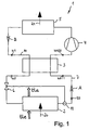
- Fig. 1
- eine schematische Darstellung einer Kälteanlage mit in einem Kreisprozess geführtem Kältemittel; und
- Fig. 2
- ein schematisches Schaubild mit Ventilkennlinien von Expansionsventilen.
- Fig. 1
- a schematic representation of a refrigeration system with guided in a cycle refrigerant; and
- Fig. 2
- a schematic diagram with valve characteristics of expansion valves.
In Fig. 1 ist schematisch eine Kälteanlage 1 gezeigt, bei der ein nicht näher dargestelltes Kältemittel in einem Kreisprozess, d.h. im Kreislauf, geführt ist.In Fig. 1, a
Die Kälteanlage 1, auch Kältemaschine genannt, hat einen Verdampfer 2, einen dem Verdampfer in Strömungsrichtung des gasförmigen Kältemittels (siehe Pfeil A) nachgeordneten inneren Wärmeaustauscher 3, einen dem inneren Wärmeaustauscher 3 nachgeordneten Verdichter 4, einen dem Verdichter nachgeordneten Verflüssiger 5, in dem das gasförmige Kältemittel kondensiert wird, wobei dem Verflüssiger 5 in Strömungsrichtung des nunmehr flüssigen Kältemittels (siehe Pfeil B) wiederum der innere Wärmeaustauscher 3 nachgeschaltet ist, und ein dem inneren Wärmeaustauscher 3 in Strömungsrichtung des flüssigen Kältemittels (siehe Pfeil B) nachgeordnetes und dem Verdampfer 2 vorgeschaltetes Expansionsventil 6.The
Die vorgenannten Komponenten sind, wie zuvor erwähnt, zu einem Kreisprozess verbunden. Dazu hat die Kälteanlage 1 vom Verdampfer 2 über den inneren Wärmeaustauscher 3 und zum Verdichter 4 eine Sauggasleitung 7. Ferner hat die Kälteanlage 1 vom Verflüssiger 5 über den inneren Wärmeaustauscher 3 und das Expansionsventil 6 zum Verdampfer 2 hin eine Flüssigkeitsleitung 10, wodurch sich letztlich der in Fig. 1 schematisch dargestellte Kreisprozess ergibt.The aforementioned components are, as previously mentioned, connected to a cyclic process. For this purpose, the
Das Expansionsventil 6 weist einen Überhitzungsfühler 11 auf.The
Erfindungsgemäß ist das Expansionsventil 6 ein solches mit einer statischen Überhitzung ≤ 2 K und ist der Überhitzungsfühler 11 in Strömungsrichtung des Kältemittels, in diesem Fall des gasförmigen Kältemittels (siehe Pfeil A), hinter dem Verdampfer 2 und vor dem inneren Wärmeaustauscher 3, mithin also in der Sauggasleitung 7 zwischen dem Verdampfer 2 und dem inneren Wärmeaustauscher 3 angeordnet.According to the invention, the
Das Expansionsventil 6 ist gemäß einer besonders bevorzugten Ausführungsform der Erfindung derart ausgebildet, dass es bereits ab einer statischen Überhitzung von 0 oder 1 K öffnet und bei einer statischen Überhitzung von etwa 4 K eine Ventilleistung von 100 % bewirkt. Das Expansionsventil 6 ist ein thermostatisches oder ein elektronisches Expansionsventil.The
In Fig. 2 sind Ventilkennlinien von thermostatischen Expansionsventilen schematisch in einem Schaubild gezeigt. Auf der Ordinate ist aufgetragen die Ventilleistung in %, auf der Abszisse ist die Überhitzung in Kelvin aufgetragen. Das erfindungsgemäße Expansionsventil 6 mit einer statischen Überhitzung ≤ 2 K hat beispielsweise eine Ventilkennlinie 12, welche in einer durchgezogenen Linie dargestellt ist, oder eine Ventilkennlinie 13, welche strichpunktiert dargestellt ist. Ein herkömmliches thermostatisches Expansionsventil nach dem Stand der Technik hat eine Ventilkennlinie 14, welche gestrichelt gezeigt ist.In Fig. 2, valve characteristics of thermostatic expansion valves are schematically shown in a diagram. On the ordinate is plotted the valve performance in%, on the abscissa the superheating in Kelvin is plotted. The
Fig. 2 verdeutlicht eine statische Überhitzung 15 in Bezug auf die gestrichelt dargestellte Ventilkennlinie 14 eines herkömmlichen Expansionsventils von etwa 5 K. Demgegenüber zeigt Fig. 2 für das erfindungsgemäße Expansionsventil gemäß der Ventilkennlinie 12 eine statische Überhitzung von 0 K und bei der anderen Ventilkennlinie 13 eines erfindungsgemäßen Expansionsventils, welche in Fig. 2 strichpunktiert dargestellt ist, eine statische Überhitzung von 1 K.Fig. 2 illustrates a static overheating 15 with respect to the dashed
Ferner ist Fig. 2 jeweils auch die Öffnungsüberhitzung 16 zu entnehmen, welche im Fall der Ventilkennlinie 14 etwa 14 K minus 5 K, also etwa 9 K und im Fall der Ventilkennlinie 12 4 K minus 0 K, also 4 K, und im Fall der Ventilkennlinie 13 4 K minus 1 K, also 3 K, beträgt. Die Summe aus jeweiliger statischer Überhitzung 15 und Öffnungsüberhitzung 16 ist dann die sogenannte Gesamt- oder Arbeitsüberhitzung 17. Diese beträgt im Falle eines herkömmlichen Expansionsventils mit der Ventilkennlinie 14 ca. 14 K, im Falle eines erfindungsgemäßen Expansionsventils mit der Ventilkennlinie 12 etwa 5 K und im Falle eines erfindungsgemäßen Expansionsventils mit der Ventilkennlinie 13 ebenfalls etwa 5 K.In addition, Fig. 2 is shown in each case also the opening superheating 16, which in the case of the
Daraus folgt, dass die statische Überhitzung von etwa 5 auf 1 bzw. 0 K reduziert wird und dass die Öffnungsüberhitzung 16 bei 100 % Ventilleistung von 7 K (12 K minus 5 K) auf 3 K (4 K minus 1 K) im Falle der Ventilkennlinie 13 bzw. auf 4 K (4 K minus 0 K) im Falle der Ventilkennlinie 12 reduziert wird.As a result, the static overheating is reduced from about 5 to 1 or 0 K and the
In der nachfolgenden Tabelle 1 sind für einen Fall A mit einer konstanten Verdampfungstemperatur t0 beispielhaft einzelne Temperaturen für eine herkömmliche Kälteanlage nach dem Stand der Technik und für eine Kälteanlage gemäß der Erfindung angegeben. In Tabelle 2 sind für einen Fall B mit einer konstanten Lufteintrittstemperatur tLe ebenfalls die sich ergebenden Temperaturen für eine Kälteanlage nach dem Stand der Technik und eine solche nach der Erfindung angegeben.In the following Table 1, for a case A with a constant evaporation temperature t0, individual temperatures are given for a conventional refrigeration system according to the prior art and for a refrigeration system according to the invention. Table 2 also shows, for a case B with a constant air inlet temperature tLe, the resulting temperatures for a prior art refrigeration system and one according to the invention.
Die einzelnen Temperaturen sind in Fig. 1 angedeutet.The individual temperatures are indicated in FIG. 1.
Die Unterkühlungstemperatur tu1 ist diejenige des flüssigen Kältemittels in Strömungsrichtung (siehe Pfeil B in Fig. 1) vor dem inneren Wärmeaustauscher 3, die Unterkühlungstemperatur tu2 diejenige des flüssigen Kältemittels nach dem inneren Wärmeaustauscher 3. Die Verdampfungstemperatur t0 wird nach dem Verdampfer 2 abgegriffen. Die Eintrittstemperatur der Luft in den Verdampfer 2, tLe bezeichnet, ist üblicherweise die von der Kälteanlage zu kühlende Luft beispielsweise eines Kühlraums. Die abgekühlte Luft tritt mit der Temperatur tLa, d.h. mit einer Luftaustrittstemperatur, welche niedriger als die Lufteintrittstemperatur ist, aus dem Verdampfer 2 aus.The subcooling temperature tu1 is that of the liquid refrigerant in the flow direction (see arrow B in FIG. 1) before the
Die Temperaturdifferenz Δt1 bezeichnet die Differenz zwischen den vorgenannten Temperaturen tLe und t0.The temperature difference Δt1 denotes the difference between the aforementioned temperatures tLe and t0.
Die Überhitzungstemperatur toh11 wird in Strömungsrichtung des gasförmigen Kältemittels (siehe Pfeil A) vor dem inneren Wärmeaustauscher 3 und die Temperatur toh22 nach dem inneren Wärmeaustauscher 3 im Bereich der Sauggasleitung 7 abgegriffen.
Aus Tabelle 1 folgt, dass es mit der erfindungsgemäßen Kälteanlage möglich ist, beispielsweise Luft aus einem Kühlraum zu kühlen, die sich schon auf einem niedrigeren Temperaturniveau als im Stand der Technik befindet. Mit einer Kälteanlage nach dem Stand der Technik kann Luft mit einer Lufteintrittstemperatur tLe von 4°C und einer Verdampfungstemperatur t0 von 0°C nicht mehr gekühlt werden, da das betreffende herkömmliche Expansionsventil gemäß dessen Ventilkennlinie 14 (siehe Fig. 2) in diesem Fall noch vollständig geschlossen ist. Eine derart geringe Überhitzung des gasförmigen Kältemittels, welche beim Temperaturniveau der Luft erfindungsgemäß zu Grunde gelegt wird, ist nicht in der Lage, die statische Überhitzung eines herkömmlichen Expansionsventils zu erreichen bzw. zu übertreffen. Daher bleibt, wie zuvor erwähnt, das herkömmliche Expansionsventil in diesem Fall geschlossen. Eine Kühlung ist damit unmöglich; die Kälteleistung beträgt 0.It follows from Table 1 that it is possible with the refrigeration system according to the invention, for example to cool air from a cold room, which is already at a lower temperature level than in the prior art. With a refrigeration system according to the prior art, air with an air inlet temperature tLe of 4 ° C and an evaporation temperature t0 of 0 ° C can no longer be cooled because the respective conventional expansion valve according to its valve characteristic 14 (see Fig. 2) in this case is completely closed. Such a slight overheating of the gaseous refrigerant, which is based on the invention at the temperature level of the air, is not able to achieve or exceed the static overheating of a conventional expansion valve. Therefore, as mentioned previously, the conventional expansion valve remains closed in this case. Cooling is thus impossible; the cooling capacity is 0.
Weiter folgt daraus, dass erfindungsgemäß Kälte bei einer treibenden Temperaturdifferenz Δt1 von nur noch 4 K produziert werden kann, was bei einer Kälteanlage nach dem Stand der Technik, wie zuvor erwähnt, nicht möglich ist.It also follows that, according to the invention, cold can be produced at a driving temperature difference Δt1 of only 4 K, which is not possible with a prior art refrigeration system, as mentioned above.
Die durch das Verdampfen des Kältemittels im Verdampfer 2 benötigte Wärmemenge 20 kann beispielsweise der Luft eines Kühlraums entzogen werden. Umgekehrt wird beim Verflüssigen des Kältemittels die Wärmemenge 21 abgegeben. Dies ist in Fig. 2 durch die Pfeile 20 bzw. 21 angedeutet.The amount of
Im Fall der Tabelle 2 kann bei identischen Lufteintrittstemperaturen tLe die Verdampfungstemperatur t0 im Falle der erfindungsgemäßen Kälteanlage deutlich höher gewählt werden, als dies bei einer Kälteanlage nach dem Stand der Technik möglich wäre. Dadurch ergibt sich zum einen der Vorteil eines geringeren Druckverhältnisses am Verdichter 4, so dass dieser im Falle der Erfindung kleiner als bei einer herkömmlichen Kälteanlage dimensioniert werden kann. Letztlich folgt daraus ein höherer Gesamtwirkungsgrad des Kälteprozesses. Ein höherer Gesamtwirkungsgrad (englisch COP - Coefficient of Performance genannt) ermöglicht letztlich ein wirtschaftlicheres Betreiben der Kälteanlage. Ferner ergibt sich der Vorteil, dass die Entfeuchtung beispielsweise eines Kühlraumes reduziert wird, so dass der darin befindlichen Ware nicht so viel Flüssigkeit wie im Falle einer herkömmlichen Kälteanlage entzogen wird. Dadurch bleibt die Qualität und das Gewicht der Ware hoch. Ein weiterer Vorteil der erfindungsgemäßen Kälteanlage besteht darin, dass bei einer im Vergleich zum Stand der Technik erhöhten Verdampfungstemperatur (laut Tabelle 2 0°C im Falle der Erfindung und - 8°C im Falle des Standes der Technik) sich der Eisaufbau und die Kondensatablagerung auf den Kühllamellen des Verdampfers reduziert. Ein weniger stark vereister Verdampfer hat aber einen besseren Wärmeübergang als ein stark vereister Verdampfer. Im Übrigen kann dadurch auch die Abtauenergie verringert werden.In the case of Table 2, at identical air inlet temperatures tLe, the evaporation temperature t0 in the case of the refrigeration system according to the invention can be selected to be significantly higher than would be possible in a refrigeration system according to the prior art. This results firstly in the advantage of a lower pressure ratio at the
Daraus ergibt sich, dass die erfindungsgemäße Kälteanlage äußerst wirtschaftlich betreibbar ist.It follows that the refrigeration system according to the invention is extremely economical to operate.
Claims (3)
mit folgenden zu einem Kreisprozess für ein Kältemittel verbundenen Komponenten:
das Expansionsventil (6) ein solches mit einer statischen Überhitzung ≤ 2 K ist und der Überhitzungsfühler (11) in Strömungsrichtung des Kältemittels hinter dem Verdampfer (2) und vor dem inneren Wärmeaustauscher (3) angeordnet ist.refrigeration plant
with the following components connected to a cycle for a refrigerant:
the expansion valve (6) is one with a static superheat ≤ 2 K and the superheat sensor (11) is arranged in the flow direction of the refrigerant behind the evaporator (2) and in front of the inner heat exchanger (3).
Applications Claiming Priority (1)
| Application Number | Priority Date | Filing Date | Title |
|---|---|---|---|
| DE202006000385U DE202006000385U1 (en) | 2006-01-11 | 2006-01-11 | refrigeration plant |
Publications (2)
| Publication Number | Publication Date |
|---|---|
| EP1808655A2 true EP1808655A2 (en) | 2007-07-18 |
| EP1808655A3 EP1808655A3 (en) | 2008-04-02 |
Family
ID=36062845
Family Applications (1)
| Application Number | Title | Priority Date | Filing Date |
|---|---|---|---|
| EP07000185A Withdrawn EP1808655A3 (en) | 2006-01-11 | 2007-01-05 | Refrigeration system |
Country Status (2)
| Country | Link |
|---|---|
| EP (1) | EP1808655A3 (en) |
| DE (1) | DE202006000385U1 (en) |
Cited By (1)
| Publication number | Priority date | Publication date | Assignee | Title |
|---|---|---|---|---|
| EP4170270A1 (en) | 2021-10-22 | 2023-04-26 | Cabero Beteiligungs-GmbH | Cooling system |
Families Citing this family (1)
| Publication number | Priority date | Publication date | Assignee | Title |
|---|---|---|---|---|
| DE102019001638A1 (en) * | 2019-03-08 | 2020-09-10 | Stiebel Eltron Gmbh & Co. Kg | Method for operating a heat pump with a vapor compression system |
Citations (10)
| Publication number | Priority date | Publication date | Assignee | Title |
|---|---|---|---|---|
| US4475686A (en) * | 1977-11-03 | 1984-10-09 | Danfoss A/S | Valve for liquid injection into a refrigerant evaporator |
| US5005370A (en) * | 1988-12-19 | 1991-04-09 | Fuji Koki Mfg. Co. Ltd. | Thermal expansion valve |
| EP1026459A1 (en) * | 1999-01-11 | 2000-08-09 | Sanden Corporation | Vapor compression type refrigeration system |
| JP2001108314A (en) * | 1999-10-05 | 2001-04-20 | Zexel Valeo Climate Control Corp | Refrigerating cycle controller |
| US6427454B1 (en) * | 2000-02-05 | 2002-08-06 | Michael K. West | Air conditioner and controller for active dehumidification while using ambient air to prevent overcooling |
| EP1369648A2 (en) * | 2002-06-04 | 2003-12-10 | Sanyo Electric Co., Ltd. | Supercritical refrigerant cycle system |
| WO2004053406A1 (en) * | 2002-12-11 | 2004-06-24 | Bms-Energietechnik Ag | Evaporation process control for use in refrigeration technology |
| WO2004055454A1 (en) * | 2002-12-14 | 2004-07-01 | Volkswagen Aktiengesellschaft | Coolant circuit for a motor vehicle air conditioning system |
| DE102004005802A1 (en) * | 2004-02-06 | 2005-08-25 | Lauda Dr. R. Wobser Gmbh & Co. Kg. | A refrigeration system has an expansion valve by which the refrigerant flow rate is controlled according to the temperature difference between the inlet and outlet of the evaporator |
| US20070074538A1 (en) * | 2005-09-07 | 2007-04-05 | Denso Corporation | Refrigeration cycle device |
-
2006
- 2006-01-11 DE DE202006000385U patent/DE202006000385U1/en not_active Expired - Lifetime
-
2007
- 2007-01-05 EP EP07000185A patent/EP1808655A3/en not_active Withdrawn
Patent Citations (10)
| Publication number | Priority date | Publication date | Assignee | Title |
|---|---|---|---|---|
| US4475686A (en) * | 1977-11-03 | 1984-10-09 | Danfoss A/S | Valve for liquid injection into a refrigerant evaporator |
| US5005370A (en) * | 1988-12-19 | 1991-04-09 | Fuji Koki Mfg. Co. Ltd. | Thermal expansion valve |
| EP1026459A1 (en) * | 1999-01-11 | 2000-08-09 | Sanden Corporation | Vapor compression type refrigeration system |
| JP2001108314A (en) * | 1999-10-05 | 2001-04-20 | Zexel Valeo Climate Control Corp | Refrigerating cycle controller |
| US6427454B1 (en) * | 2000-02-05 | 2002-08-06 | Michael K. West | Air conditioner and controller for active dehumidification while using ambient air to prevent overcooling |
| EP1369648A2 (en) * | 2002-06-04 | 2003-12-10 | Sanyo Electric Co., Ltd. | Supercritical refrigerant cycle system |
| WO2004053406A1 (en) * | 2002-12-11 | 2004-06-24 | Bms-Energietechnik Ag | Evaporation process control for use in refrigeration technology |
| WO2004055454A1 (en) * | 2002-12-14 | 2004-07-01 | Volkswagen Aktiengesellschaft | Coolant circuit for a motor vehicle air conditioning system |
| DE102004005802A1 (en) * | 2004-02-06 | 2005-08-25 | Lauda Dr. R. Wobser Gmbh & Co. Kg. | A refrigeration system has an expansion valve by which the refrigerant flow rate is controlled according to the temperature difference between the inlet and outlet of the evaporator |
| US20070074538A1 (en) * | 2005-09-07 | 2007-04-05 | Denso Corporation | Refrigeration cycle device |
Non-Patent Citations (1)
| Title |
|---|
| CHEN W ET AL: "Experimental investigation of a minimum stable superheat control system of an evaporator" INTERNATIONAL JOURNAL OF REFRIGERATION, OXFORD, GB, Bd. 25, Nr. 8, Dezember 2002 (2002-12), Seiten 1137-1142, XP004388595 ISSN: 0140-7007 * |
Cited By (2)
| Publication number | Priority date | Publication date | Assignee | Title |
|---|---|---|---|---|
| EP4170270A1 (en) | 2021-10-22 | 2023-04-26 | Cabero Beteiligungs-GmbH | Cooling system |
| DE102021127498A1 (en) | 2021-10-22 | 2023-04-27 | Cabero Beteiligungs-Gmbh | cooling system |
Also Published As
| Publication number | Publication date |
|---|---|
| EP1808655A3 (en) | 2008-04-02 |
| DE202006000385U1 (en) | 2006-03-02 |
Similar Documents
| Publication | Publication Date | Title |
|---|---|---|
| DE69930732T2 (en) | COOLING SYSTEM | |
| EP2906882B1 (en) | Refrigerator with two evaporators | |
| DE3907859C2 (en) | Air-cooled refrigeration unit with a coolant circuit | |
| WO2009141282A2 (en) | Cooling appliance storing coolant in the condenser, and corresponding method | |
| WO2009080517A1 (en) | Cooling appliance | |
| EP1576321A2 (en) | Refrigerant circuit and a refrigerating system | |
| EP1745248B1 (en) | Cooling system and method for producing an evaporation plate for a low-temperature cooling system | |
| DE102005049950B4 (en) | Method for generating low temperatures and a cascade refrigeration system operating thereafter | |
| DE102008043807B4 (en) | refrigeration plant | |
| DE19920726A1 (en) | Refrigeration system | |
| EP1808655A2 (en) | Refrigeration system | |
| DE10001470A1 (en) | Method for operating climate control in vehicles involves connecting precipitate collector in on input side of evaporator which is mainly loaded with coolant from same | |
| DE102007018439B3 (en) | refrigeration plant | |
| EP2187149A2 (en) | Heat pump assembly | |
| DE102007025319B4 (en) | Refrigeration system with gas exchanger operated as a heat exchanger | |
| DE19832682C2 (en) | Defrosting device for an evaporator of a heat pump or an air conditioner | |
| DE102015221441A1 (en) | Refrigeration device with a throttle element | |
| EP1498673B1 (en) | Hot gas defrost system for refrigeration systems | |
| EP1980803B1 (en) | Method for operating a heat pump | |
| DE102006026354B4 (en) | Refrigeration system with internal heat exchanger and controlled expansion valve | |
| EP2796812A1 (en) | Refrigeration and/or freezer device | |
| DE202018001404U1 (en) | Device for tempering filter-cleaned liquid medium | |
| DE10322674A1 (en) | Method for reducing the noise of a refrigeration circuit during expansion of the refrigerant, has a capillary section between the first cooling section and the main evaporators on the same base plate | |
| CH665708A5 (en) | METHOD FOR OPERATING A REFRIGERANT CIRCUIT AND REFRIGERANT CIRCUIT FOR CARRYING OUT THE METHOD. | |
| DE102018002120A1 (en) | Device for tempering filter-cleaned liquid medium |
Legal Events
| Date | Code | Title | Description |
|---|---|---|---|
| PUAI | Public reference made under article 153(3) epc to a published international application that has entered the european phase |
Free format text: ORIGINAL CODE: 0009012 |
|
| AK | Designated contracting states |
Kind code of ref document: A2 Designated state(s): AT BE BG CH CY CZ DE DK EE ES FI FR GB GR HU IE IS IT LI LT LU LV MC NL PL PT RO SE SI SK TR |
|
| AX | Request for extension of the european patent |
Extension state: AL BA HR MK YU |
|
| 17P | Request for examination filed |
Effective date: 20070816 |
|
| PUAL | Search report despatched |
Free format text: ORIGINAL CODE: 0009013 |
|
| AK | Designated contracting states |
Kind code of ref document: A3 Designated state(s): AT BE BG CH CY CZ DE DK EE ES FI FR GB GR HU IE IS IT LI LT LU LV MC NL PL PT RO SE SI SK TR |
|
| AX | Request for extension of the european patent |
Extension state: AL BA HR MK YU |
|
| RIC1 | Information provided on ipc code assigned before grant |
Ipc: F25B 49/02 20060101ALI20080226BHEP Ipc: F25B 41/06 20060101ALI20080226BHEP Ipc: F25B 40/00 20060101AFI20070510BHEP |
|
| STAA | Information on the status of an ep patent application or granted ep patent |
Free format text: STATUS: THE APPLICATION HAS BEEN WITHDRAWN |
|
| 18W | Application withdrawn |
Effective date: 20080411 |