EP1826121A2 - Gap lightning surface protection of composite structures - Google Patents
Gap lightning surface protection of composite structures Download PDFInfo
- Publication number
- EP1826121A2 EP1826121A2 EP07075116A EP07075116A EP1826121A2 EP 1826121 A2 EP1826121 A2 EP 1826121A2 EP 07075116 A EP07075116 A EP 07075116A EP 07075116 A EP07075116 A EP 07075116A EP 1826121 A2 EP1826121 A2 EP 1826121A2
- Authority
- EP
- European Patent Office
- Prior art keywords
- composite
- conductive
- ply
- fastener
- lightning
- Prior art date
- Legal status (The legal status is an assumption and is not a legal conclusion. Google has not performed a legal analysis and makes no representation as to the accuracy of the status listed.)
- Granted
Links
Images


Classifications
-
- B—PERFORMING OPERATIONS; TRANSPORTING
- B64—AIRCRAFT; AVIATION; COSMONAUTICS
- B64D—EQUIPMENT FOR FITTING IN OR TO AIRCRAFT; FLIGHT SUITS; PARACHUTES; ARRANGEMENTS OR MOUNTING OF POWER PLANTS OR PROPULSION TRANSMISSIONS IN AIRCRAFT
- B64D45/00—Aircraft indicators or protectors not otherwise provided for
- B64D45/02—Lightning protectors; Static dischargers
-
- H—ELECTRICITY
- H01—ELECTRIC ELEMENTS
- H01T—SPARK GAPS; OVERVOLTAGE ARRESTERS USING SPARK GAPS; SPARKING PLUGS; CORONA DEVICES; GENERATING IONS TO BE INTRODUCED INTO NON-ENCLOSED GASES
- H01T4/00—Overvoltage arresters using spark gaps
- H01T4/08—Overvoltage arresters using spark gaps structurally associated with protected apparatus
Definitions
- the present invention relates to lightning protection and more particularly, preventing lightning from puncturing composite surfaces.
- External composite surfaces are susceptible to puncture when exposed to direct lightning attachment.
- Composite surfaces with underlying systems, such as hydraulic lines or fuel tubing, or structure require protection against the adverse effects of lightning because a puncture in the composite surface could result in a catastrophic failure, such as a spark in a fuel tank.
- metal foils or interwoven wires are added to the composite surface. Although the addition of the metal foils or interwoven wires protects against the attachment of the lightning to the underlying systems, they are heavy, difficult to apply and require special processes to prevent surface cracking due to coefficient of thermal expansion differences.
- a method of preventing lighting from puncturing composite surfaces includes reconfiguring plies of a composite surface so that a conductive ply is located on the outer surface of the composite surface and a non-conductive ply is located directly underneath the conductive ply and inserting a flashover point between an outer edge of the conductive ply and a fastener attaching the composite surface to a support structure.
- a protection system for preventing lightning from puncturing composite surfaces includes a composite surface having a composite conductive ply directly on top of non-conductive composite ply; a support structure; and a flashover device, between an outer edge of the conductive ply and a fastener, attaching the composite surface to the support structure.
- FIG. 1 a illustrates a typical prior art composite panel exposed to lightning
- Figure 1 b illustrates a typical prior art fixed leading edge composite surface exposed to lightning
- Figure 2a illustrates a side view of a composite panel, according to one aspect of the present invention
- Figure 2b illustrates a top view of the composite panel in Figure 2a having a conductive strip
- Figure 2c illustrates a top view of the composite panel in Figure 2a having a leader initiator insert
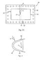
- Figure 3 illustrates a fixed leading edge composite panel, according to one aspect of the present invention.
- an improved, cost effective and light weight protection method and system to prevent lightning from puncturing composite surfaces is provided.
- the method of the present invention is implemented using an aircraft, those skilled in the art will recognize that the principles and teachings described herein may be applied to a variety of structures with composite surfaces, such as automobiles and antenna radomes.
- Figures 1 a and 1b illustrate a typical prior art composite panel 2 and fixed leading edge composite panel 4 exposed to lightning 6. Direct contact of lightning 6 can occur on panels with conductive or non-conductive plies that cover underlying systems (or "structures") 8 located close to inner surfaces 10, 12 of panels 2, 4. Non-conductive plies 14 are electrically transparent to lightning 6 and are subject to puncture, while conductive plies in composite panels may not be thick enough to prevent puncture.
- Conventional composite panels 2, 4 are comprised of several plies 26 of fiberglass stacked up.
- fiberglass is mixed with carbon fiber reinforced plastic (CFRP)
- CFRP carbon fiber reinforced plastic
- a hybrid ply can be comprised of fiberglass, KEVLAR® or the combination of fiberglass or KEVLAR® and CFRP.
- a composite panel 28 according to the present invention is provided.
- the configuration of the stack up of the plies in composite panel 28 is re-arranged so that a conductive ply 24 is located on the outer surface of composite panel 28 and is directly on top of a non-conductive ply 30.
- composite panels can be provided the same level of protection against lightning attachment 27 at less cost, less weight and greater simplicity.
- the first two plies 24, 30 play a crucial role in preventing puncture and by configuring non-conductive ply 30 under conductive ply 24, lightning currents to conductive ply 28 of composite panel 28 are isolated.
- the remaining underlying plies can be configured in any order.
- a flashover point (or “device”) 32 is added between edge 34 of outer conductive ply 24, generally comprised of CFRP, and first fastener 20 to prevent galvanic corrosion as the carbon fibers in the CFRP do not come into contact with first fastener 20.
- Flashover (or “device”) 32 creates a length or distance "d", which is the distance between edge 34 of outer conductive ply 24 and first fastener 20, to minimize the likelihood of puncture to underlying systems 8 as the flashover voltage between conductive ply 24 and first fastener 20 will be reduced.
- System 8 can be any underlying system, for example, a fuel tube, hydraulic systems or any other system.
- lightning 6 attaching to underlying systems 8, the current produced by lightning 6 flashes over and flows through first fastener 20. In other words, lightning 6 attaches to conductive ply 24 causing current to flow through conductive surface 24 and flash over distance "d" to first fastener 20.
- distance “d” is a quarter inch (0.25 in) so voltage occurs between conductive ply 24 and first fastener 20, while allowing the current to divert along the surface of panel 28 only and not puncture and attach to underlying systems 8.
- Flashover (or “device”) 32 provides a lightning current path to surrounding structure.
- a conductive strip 38 is applied from conductive ply 24 to a second fastener 22 of composite panel 28.
- Conductive strip 38 reduces the voltage required for lightning current to flow from conductive ply 24 over to second fastener 22.
- Conductive strip 38 is made from copper or other type of (galvanically compatible metal) conductive material that electrically grounds conductive ply 24 to second fastener 22. Conductive strip 38 can be part of the lay up built into composite panel 28.
- leader initiator insert 40 can be inserted on a third fastener 42, as shown in the top-view of Figure 2c.
- Leader initiator insert 40 is comprised of metal and has a sharp point directed toward the edge of conductive ply 24 to reduce flashover voltage and the likelihood of puncture.
- Leader initiator insert 40 is only required if distance "d" is large enough to cause the flashover voltage to be greater than the puncture voltage. For example, if the design of a composite panel requires distance "d" to be an inch between conductive ply 24 and first fastener 20 to prevent corrosion, leader initiator insert 40 can also be inserted so lightning protection is provided and galvanic corrosion is prevented.
- FIG 3 illustrates the method and system described above applied to a fixed leading edge composite panel 44.
- Lightning 6 attaches to a conductive ply of fixed leading edge composite panel 44 producing a current which causes an arc of voltage 46 on outer surface 48 of panel 44.
- lightning 6 does not attach to underlying systems 8 preventing a failure of underlying systems 8.
Abstract
Description
- The present invention relates to lightning protection and more particularly, preventing lightning from puncturing composite surfaces.
- External composite surfaces are susceptible to puncture when exposed to direct lightning attachment. Composite surfaces with underlying systems, such as hydraulic lines or fuel tubing, or structure require protection against the adverse effects of lightning because a puncture in the composite surface could result in a catastrophic failure, such as a spark in a fuel tank. Typically, to provide protection against lightning, metal foils or interwoven wires are added to the composite surface. Although the addition of the metal foils or interwoven wires protects against the attachment of the lightning to the underlying systems, they are heavy, difficult to apply and require special processes to prevent surface cracking due to coefficient of thermal expansion differences.
- Parts of aircrafts, such as the fixed wing, wing to body fairing and empennage are being increasingly constructed of composite surfaces. It has been estimated that on average, each airplane in the U.S. commercial fleet is struck by lightning more than once each year. In fact, aircraft often trigger lightning when flying through a heavily charged region of a cloud. In these instances, the lightning flash originates at the airplane and extends away in opposite directions. To prevent catastrophic failures, a method and system are needed for preventing lightning from puncturing composite surfaces that are cost effective and add minimal parasitic weight.
- In one aspect of the present invention, a method of preventing lighting from puncturing composite surfaces is provided. The method includes reconfiguring plies of a composite surface so that a conductive ply is located on the outer surface of the composite surface and a non-conductive ply is located directly underneath the conductive ply and inserting a flashover point between an outer edge of the conductive ply and a fastener attaching the composite surface to a support structure.
- In another aspect of the present invention, a protection system for preventing lightning from puncturing composite surfaces is provided. The system includes a composite surface having a composite conductive ply directly on top of non-conductive composite ply; a support structure; and a flashover device, between an outer edge of the conductive ply and a fastener, attaching the composite surface to the support structure.
- This brief summary has been provided so that the nature of the invention may be understood quickly. A more complete understanding of the invention can be obtained by reference to the following detailed description of the preferred embodiments thereof in connection with the attached drawings.
- The foregoing features and other features of the present invention will now be described with reference to the drawings of a preferred embodiment. In the drawings, the same components have the same reference numerals. The illustrated embodiment is intended to illustrate, but not to limit the invention. The drawings include the following Figures:
- Figures 1 a illustrates a typical prior art composite panel exposed to lightning;
- Figure 1 b illustrates a typical prior art fixed leading edge composite surface exposed to lightning;
- Figure 2a illustrates a side view of a composite panel, according to one aspect of the present invention;
- Figure 2b illustrates a top view of the composite panel in Figure 2a having a conductive strip;
- Figure 2c illustrates a top view of the composite panel in Figure 2a having a leader initiator insert; and
- Figure 3 illustrates a fixed leading edge composite panel, according to one aspect of the present invention.
- The following detailed description is of the best currently contemplated modes of carrying out the invention. The description is not to be taken in a limiting sense, but is made merely for the purpose of illustrating the general principles of the invention, since the scope of the invention is best defined by the appended claims.
- According to the present invention, an improved, cost effective and light weight protection method and system to prevent lightning from puncturing composite surfaces (or "panels" or "structures") is provided. Although the method of the present invention is implemented using an aircraft, those skilled in the art will recognize that the principles and teachings described herein may be applied to a variety of structures with composite surfaces, such as automobiles and antenna radomes.
- Figures 1 a and 1b illustrate a typical prior
art composite panel 2 and fixed leadingedge composite panel 4 exposed tolightning 6. Direct contact oflightning 6 can occur on panels with conductive or non-conductive plies that cover underlying systems (or "structures") 8 located close toinner surfaces panels plies 14 are electrically transparent to lightning 6 and are subject to puncture, while conductive plies in composite panels may not be thick enough to prevent puncture. - Traditional methods and systems of preventing punctures to protection systems have included adding metallized surface protection on
outer surfaces 16, 18 ofcomposite panels lightning 6 to flow throughouter surfaces 16, 18 ofpanels second fasteners -
Conventional composite panels several plies 26 of fiberglass stacked up. By changingcomposite panels - Turning to Figures 2a-c, a
composite panel 28 according to the present invention is provided. The configuration of the stack up of the plies incomposite panel 28 is re-arranged so that aconductive ply 24 is located on the outer surface ofcomposite panel 28 and is directly on top of anon-conductive ply 30. As a result, composite panels can be provided the same level of protection againstlightning attachment 27 at less cost, less weight and greater simplicity. The first twoplies non-conductive ply 30 underconductive ply 24, lightning currents toconductive ply 28 ofcomposite panel 28 are isolated. The remaining underlying plies can be configured in any order. - In addition to re-arranging the ply lay up, a flashover point (or "device") 32 is added between
edge 34 of outerconductive ply 24, generally comprised of CFRP, andfirst fastener 20 to prevent galvanic corrosion as the carbon fibers in the CFRP do not come into contact withfirst fastener 20. When lightning attaches 6 anywhere on outerconductive ply 24, a voltage occurs betweenedge 34 of outerconductive ply 24 andfirst fastener 20. If this voltage is high enough to create an ionized path betweenedge 34 of outerconductive ply 24 and fastener edge 36, puncture will occur. Flashover (or "device") 32 creates a length or distance "d", which is the distance betweenedge 34 of outerconductive ply 24 andfirst fastener 20, to minimize the likelihood of puncture tounderlying systems 8 as the flashover voltage betweenconductive ply 24 andfirst fastener 20 will be reduced.System 8 can be any underlying system, for example, a fuel tube, hydraulic systems or any other system. Instead oflightning 6 attaching tounderlying systems 8, the current produced bylightning 6 flashes over and flows throughfirst fastener 20. In other words,lightning 6 attaches toconductive ply 24 causing current to flow throughconductive surface 24 and flash over distance "d" to first fastener 20. - In a preferred embodiment, distance "d" is a quarter inch (0.25 in) so voltage occurs between
conductive ply 24 andfirst fastener 20, while allowing the current to divert along the surface ofpanel 28 only and not puncture and attach tounderlying systems 8. Flashover (or "device") 32 provides a lightning current path to surrounding structure. - If distance "d" is required to be so large that the resulting flashover voltage is greater than the puncture voltage, additional devices, such as conductive strips and leader initiator inserts are required to prevent puncture. As shown in the top-view of Figure 2b, a
conductive strip 38 is applied fromconductive ply 24 to asecond fastener 22 ofcomposite panel 28.Conductive strip 38 reduces the voltage required for lightning current to flow fromconductive ply 24 over tosecond fastener 22.Conductive strip 38 is made from copper or other type of (galvanically compatible metal) conductive material that electrically groundsconductive ply 24 tosecond fastener 22.Conductive strip 38 can be part of the lay up built intocomposite panel 28. - Alternatively, a leader initiator insert 40 can be inserted on a
third fastener 42, as shown in the top-view of Figure 2c.Leader initiator insert 40 is comprised of metal and has a sharp point directed toward the edge ofconductive ply 24 to reduce flashover voltage and the likelihood of puncture.Leader initiator insert 40 is only required if distance "d" is large enough to cause the flashover voltage to be greater than the puncture voltage. For example, if the design of a composite panel requires distance "d" to be an inch betweenconductive ply 24 andfirst fastener 20 to prevent corrosion, leader initiator insert 40 can also be inserted so lightning protection is provided and galvanic corrosion is prevented. - Figure 3 illustrates the method and system described above applied to a fixed leading edge
composite panel 44.Lightning 6 attaches to a conductive ply of fixed leading edgecomposite panel 44 producing a current which causes an arc ofvoltage 46 onouter surface 48 ofpanel 44. As a result,lightning 6 does not attach tounderlying systems 8 preventing a failure ofunderlying systems 8.
Although the present invention has been described with reference to specific embodiments, these embodiments are illustrative only and not limiting. Many other applications and embodiments of the present invention will be apparent in light of this disclosure and the following claims.
Claims (9)
- A method of preventing lighting from puncturing composite surfaces, comprising:reconfiguring plies of a composite surface so that a composite conductive ply is located on the outer surface of the composite surface and a non-conductive composite ply is located directly underneath the conductive ply; andinserting a flashover point, between an outer edge of the composite conductive ply and a fastener, attaching the composite surface to a support structure.
- The method of claim 1, further comprising placing a conductive strip between the composite conductive ply and the fastener.
- The method of claim 1 or 2, further comprising placing a pointed leader initiator insert inserted over the fastener with the point directed toward the edge of the composite conductive ply.
- The method of claim 2 or 3, wherein the conductive strip reduces the voltage required for lightning current to flow from the composite conductive ply over to the fastener.
- A protection system for preventing lightning from puncturing composite surfaces, comprising:a composite surface having a composite conductive ply directly on top of non-conductive composite ply; a support structure; anda flashover device, between an outer edge of the conductive ply and a fastener, attaching the composite surface to the support structure.
- The system of claim 5, wherein the length of the flashover device is .25 cm.
- The system of claim 5 or 6, wherein the composite conductive ply is comprised of CFRP.
- The system of claim 5, 6 or 7, wherein the non-conductive ply is selected from the group consisting of KEVLAR® and fiberglass.
- the system of any of claims 5-8, wherein the method of any of claims 1-4 is used.
Applications Claiming Priority (1)
| Application Number | Priority Date | Filing Date | Title |
|---|---|---|---|
| US11/361,924 US7561402B2 (en) | 2006-02-24 | 2006-02-24 | Gap lightning surface protection of composite structures |
Publications (3)
| Publication Number | Publication Date |
|---|---|
| EP1826121A2 true EP1826121A2 (en) | 2007-08-29 |
| EP1826121A3 EP1826121A3 (en) | 2009-12-02 |
| EP1826121B1 EP1826121B1 (en) | 2012-04-11 |
Family
ID=38117062
Family Applications (1)
| Application Number | Title | Priority Date | Filing Date |
|---|---|---|---|
| EP07075116A Active EP1826121B1 (en) | 2006-02-24 | 2007-02-09 | Gap lightning surface protection of composite structures |
Country Status (4)
| Country | Link |
|---|---|
| US (1) | US7561402B2 (en) |
| EP (1) | EP1826121B1 (en) |
| AT (1) | ATE553030T1 (en) |
| CA (1) | CA2579270C (en) |
Cited By (1)
| Publication number | Priority date | Publication date | Assignee | Title |
|---|---|---|---|---|
| RU2466912C1 (en) * | 2011-07-01 | 2012-11-20 | Федеральное государственное бюджетное образовательное учреждение высшего профессионального образования "Национальный исследовательский университет "МЭИ" | Anti-lightning device for aircraft nose cone and antenna accommodated therein |
Families Citing this family (7)
| Publication number | Priority date | Publication date | Assignee | Title |
|---|---|---|---|---|
| US9586699B1 (en) | 1999-08-16 | 2017-03-07 | Smart Drilling And Completion, Inc. | Methods and apparatus for monitoring and fixing holes in composite aircraft |
| US9625361B1 (en) | 2001-08-19 | 2017-04-18 | Smart Drilling And Completion, Inc. | Methods and apparatus to prevent failures of fiber-reinforced composite materials under compressive stresses caused by fluids and gases invading microfractures in the materials |
| KR101711226B1 (en) | 2009-04-17 | 2017-02-28 | 쓰리엠 이노베이티브 프로퍼티즈 컴파니 | Lightning protection sheet with patterned conductor |
| BRPI1006590B1 (en) | 2009-04-17 | 2020-04-14 | 3M Innovative Properties Co | lightning protection coating |
| US8922961B2 (en) * | 2009-09-25 | 2014-12-30 | Hamilton Sundstrand Corporation | Two-level lightning protection circuit |
| US9702255B2 (en) * | 2013-11-26 | 2017-07-11 | Textron Innovations, Inc. | Propeller with lightening strike protection |
| JP6770987B2 (en) * | 2018-03-12 | 2020-10-21 | 株式会社Subaru | Composite structure, aircraft and lightning current induction method |
Citations (1)
| Publication number | Priority date | Publication date | Assignee | Title |
|---|---|---|---|---|
| US5698316A (en) | 1996-10-07 | 1997-12-16 | The Boeing Company | Apparatus and methods of providing corrosion resistant conductive path across non conductive joints or gaps |
Family Cites Families (10)
| Publication number | Priority date | Publication date | Assignee | Title |
|---|---|---|---|---|
| US3755713A (en) * | 1972-07-25 | 1973-08-28 | Boeing Co | Electrically conductive surface for aircraft |
| US3989984A (en) * | 1975-07-11 | 1976-11-02 | Mcdonnell Douglas Corporation | Aircraft lightning protection means |
| US4448838A (en) * | 1981-09-04 | 1984-05-15 | Lear Fan Corp. | Graphite fiber reinforced laminate structure capable of withstanding lightning strikes |
| EP0089949A4 (en) * | 1981-09-28 | 1985-09-16 | Boeing Co | Grounding terminal for lightning diverter strip. |
| US4628402A (en) * | 1985-09-30 | 1986-12-09 | The Boeing Company | Lightning protection of fasteners in composite material |
| US4796153A (en) * | 1987-06-01 | 1989-01-03 | Lightning Diversion Systems | Lightning diversion strips for aircraft |
| FR2741590B1 (en) * | 1995-11-29 | 1998-01-30 | Eurocopter France | BLADE WITH REINFORCED PROTECTION AGAINST LIGHTNING, FOR ROTOR OF A GIRAVION |
| FR2745124B1 (en) * | 1996-02-15 | 1998-04-10 | Bocherens Eric | SPRING STRIP |
| US6582172B2 (en) * | 2001-08-29 | 2003-06-24 | The United States Of America As Represented By The Secretary Of The Navy | Isolated mechanical fastening system |
| ES2264299B1 (en) * | 2003-06-06 | 2007-11-16 | Airbus España S.L. | LIGHTNING PROTECTION SYSTEM FOR FUEL TANKS MANUFACTURED IN POOR ELECTRICAL CONDUCTIVITY MATERIALS. |
-
2006
- 2006-02-24 US US11/361,924 patent/US7561402B2/en active Active
-
2007
- 2007-02-09 AT AT07075116T patent/ATE553030T1/en active
- 2007-02-09 EP EP07075116A patent/EP1826121B1/en active Active
- 2007-02-21 CA CA2579270A patent/CA2579270C/en active Active
Patent Citations (1)
| Publication number | Priority date | Publication date | Assignee | Title |
|---|---|---|---|---|
| US5698316A (en) | 1996-10-07 | 1997-12-16 | The Boeing Company | Apparatus and methods of providing corrosion resistant conductive path across non conductive joints or gaps |
Cited By (1)
| Publication number | Priority date | Publication date | Assignee | Title |
|---|---|---|---|---|
| RU2466912C1 (en) * | 2011-07-01 | 2012-11-20 | Федеральное государственное бюджетное образовательное учреждение высшего профессионального образования "Национальный исследовательский университет "МЭИ" | Anti-lightning device for aircraft nose cone and antenna accommodated therein |
Also Published As
| Publication number | Publication date |
|---|---|
| US20070201179A1 (en) | 2007-08-30 |
| EP1826121A3 (en) | 2009-12-02 |
| EP1826121B1 (en) | 2012-04-11 |
| US7561402B2 (en) | 2009-07-14 |
| CA2579270C (en) | 2013-04-23 |
| ATE553030T1 (en) | 2012-04-15 |
| CA2579270A1 (en) | 2007-08-24 |
Similar Documents
| Publication | Publication Date | Title |
|---|---|---|
| EP1826121B1 (en) | Gap lightning surface protection of composite structures | |
| US7599164B2 (en) | Lightning protection system for aircraft composite structure | |
| US8436243B2 (en) | Anti-lightning system and aircraft comprising such a system | |
| US7236343B2 (en) | Method and system for lightning current conduction protection using foil bonded strips | |
| EP1944236B1 (en) | Light weight system for lightning protection of nonconductive aircraft panels | |
| US7554785B2 (en) | Lightning damage protection for composite aircraft | |
| EP2143638A2 (en) | Lightning protection system for an aircraft composite structure | |
| CN101896402B (en) | Anti-lightning system and aircraft comprising such a system | |
| US3989984A (en) | Aircraft lightning protection means | |
| EP2196391A2 (en) | Impact resistant aircraft leading edge structures and aircraft including the same | |
| US8746611B2 (en) | Lightning protection arrangement for an electronic unit | |
| EP1549545B1 (en) | Lightning strike protection and grounding of a composite aircraft panel | |
| RU2465176C2 (en) | System for drainage of lightning current generated by lightning discharge onto aircraft | |
| EP0217314A2 (en) | Lightning protection of fasteners in composite material | |
| US20090140098A1 (en) | Component with carbon nanotubes | |
| US9758237B2 (en) | Aircraft wire fairing | |
| EP3106291B1 (en) | Enhancing z-conductivity in carbon fiber reinforced plastic composite layups | |
| US9702255B2 (en) | Propeller with lightening strike protection | |
| EP3156321B1 (en) | Composite stiffener with integral conductive element | |
| EP2465776B1 (en) | Lightning and corrosion protection arrangement in an aircraft structural component | |
| US10450087B2 (en) | Lightning strike dispersion for composite aircraft structures | |
| US10329031B2 (en) | Electricity dispersion for aircraft evacuation assemblies | |
| EP3511579B1 (en) | Fastening structure |
Legal Events
| Date | Code | Title | Description |
|---|---|---|---|
| PUAI | Public reference made under article 153(3) epc to a published international application that has entered the european phase |
Free format text: ORIGINAL CODE: 0009012 |
|
| AK | Designated contracting states |
Kind code of ref document: A2 Designated state(s): AT BE BG CH CY CZ DE DK EE ES FI FR GB GR HU IE IS IT LI LT LU LV MC NL PL PT RO SE SI SK TR |
|
| AX | Request for extension of the european patent |
Extension state: AL BA HR MK YU |
|
| PUAL | Search report despatched |
Free format text: ORIGINAL CODE: 0009013 |
|
| AK | Designated contracting states |
Kind code of ref document: A3 Designated state(s): AT BE BG CH CY CZ DE DK EE ES FI FR GB GR HU IE IS IT LI LT LU LV MC NL PL PT RO SE SI SK TR |
|
| AX | Request for extension of the european patent |
Extension state: AL BA HR MK RS |
|
| 17P | Request for examination filed |
Effective date: 20091215 |
|
| 17Q | First examination report despatched |
Effective date: 20100113 |
|
| AKX | Designation fees paid |
Designated state(s): AT BE BG CH CY CZ DE DK EE ES FI FR GB GR HU IE IS IT LI LT LU LV MC NL PL PT RO SE SI SK TR |
|
| GRAP | Despatch of communication of intention to grant a patent |
Free format text: ORIGINAL CODE: EPIDOSNIGR1 |
|
| GRAS | Grant fee paid |
Free format text: ORIGINAL CODE: EPIDOSNIGR3 |
|
| GRAA | (expected) grant |
Free format text: ORIGINAL CODE: 0009210 |
|
| AK | Designated contracting states |
Kind code of ref document: B1 Designated state(s): AT BE BG CH CY CZ DE DK EE ES FI FR GB GR HU IE IS IT LI LT LU LV MC NL PL PT RO SE SI SK TR |
|
| REG | Reference to a national code |
Ref country code: GB Ref legal event code: FG4D |
|
| REG | Reference to a national code |
Ref country code: CH Ref legal event code: EP |
|
| REG | Reference to a national code |
Ref country code: AT Ref legal event code: REF Ref document number: 553030 Country of ref document: AT Kind code of ref document: T Effective date: 20120415 |
|
| REG | Reference to a national code |
Ref country code: IE Ref legal event code: FG4D |
|
| REG | Reference to a national code |
Ref country code: DE Ref legal event code: R096 Ref document number: 602007021834 Country of ref document: DE Effective date: 20120606 |
|
| REG | Reference to a national code |
Ref country code: NL Ref legal event code: VDEP Effective date: 20120411 |
|
| REG | Reference to a national code |
Ref country code: AT Ref legal event code: MK05 Ref document number: 553030 Country of ref document: AT Kind code of ref document: T Effective date: 20120411 |
|
| LTIE | Lt: invalidation of european patent or patent extension |
Effective date: 20120411 |
|
| PG25 | Lapsed in a contracting state [announced via postgrant information from national office to epo] |
Ref country code: IS Free format text: LAPSE BECAUSE OF FAILURE TO SUBMIT A TRANSLATION OF THE DESCRIPTION OR TO PAY THE FEE WITHIN THE PRESCRIBED TIME-LIMIT Effective date: 20120811 Ref country code: CY Free format text: LAPSE BECAUSE OF FAILURE TO SUBMIT A TRANSLATION OF THE DESCRIPTION OR TO PAY THE FEE WITHIN THE PRESCRIBED TIME-LIMIT Effective date: 20120411 Ref country code: FI Free format text: LAPSE BECAUSE OF FAILURE TO SUBMIT A TRANSLATION OF THE DESCRIPTION OR TO PAY THE FEE WITHIN THE PRESCRIBED TIME-LIMIT Effective date: 20120411 Ref country code: PL Free format text: LAPSE BECAUSE OF FAILURE TO SUBMIT A TRANSLATION OF THE DESCRIPTION OR TO PAY THE FEE WITHIN THE PRESCRIBED TIME-LIMIT Effective date: 20120411 Ref country code: LT Free format text: LAPSE BECAUSE OF FAILURE TO SUBMIT A TRANSLATION OF THE DESCRIPTION OR TO PAY THE FEE WITHIN THE PRESCRIBED TIME-LIMIT Effective date: 20120411 Ref country code: SE Free format text: LAPSE BECAUSE OF FAILURE TO SUBMIT A TRANSLATION OF THE DESCRIPTION OR TO PAY THE FEE WITHIN THE PRESCRIBED TIME-LIMIT Effective date: 20120411 |
|
| PG25 | Lapsed in a contracting state [announced via postgrant information from national office to epo] |
Ref country code: GR Free format text: LAPSE BECAUSE OF FAILURE TO SUBMIT A TRANSLATION OF THE DESCRIPTION OR TO PAY THE FEE WITHIN THE PRESCRIBED TIME-LIMIT Effective date: 20120712 Ref country code: LV Free format text: LAPSE BECAUSE OF FAILURE TO SUBMIT A TRANSLATION OF THE DESCRIPTION OR TO PAY THE FEE WITHIN THE PRESCRIBED TIME-LIMIT Effective date: 20120411 Ref country code: SI Free format text: LAPSE BECAUSE OF FAILURE TO SUBMIT A TRANSLATION OF THE DESCRIPTION OR TO PAY THE FEE WITHIN THE PRESCRIBED TIME-LIMIT Effective date: 20120411 Ref country code: PT Free format text: LAPSE BECAUSE OF FAILURE TO SUBMIT A TRANSLATION OF THE DESCRIPTION OR TO PAY THE FEE WITHIN THE PRESCRIBED TIME-LIMIT Effective date: 20120813 |
|
| PG25 | Lapsed in a contracting state [announced via postgrant information from national office to epo] |
Ref country code: BE Free format text: LAPSE BECAUSE OF FAILURE TO SUBMIT A TRANSLATION OF THE DESCRIPTION OR TO PAY THE FEE WITHIN THE PRESCRIBED TIME-LIMIT Effective date: 20120411 |
|
| PG25 | Lapsed in a contracting state [announced via postgrant information from national office to epo] |
Ref country code: DK Free format text: LAPSE BECAUSE OF FAILURE TO SUBMIT A TRANSLATION OF THE DESCRIPTION OR TO PAY THE FEE WITHIN THE PRESCRIBED TIME-LIMIT Effective date: 20120411 Ref country code: RO Free format text: LAPSE BECAUSE OF FAILURE TO SUBMIT A TRANSLATION OF THE DESCRIPTION OR TO PAY THE FEE WITHIN THE PRESCRIBED TIME-LIMIT Effective date: 20120411 Ref country code: NL Free format text: LAPSE BECAUSE OF FAILURE TO SUBMIT A TRANSLATION OF THE DESCRIPTION OR TO PAY THE FEE WITHIN THE PRESCRIBED TIME-LIMIT Effective date: 20120411 Ref country code: SK Free format text: LAPSE BECAUSE OF FAILURE TO SUBMIT A TRANSLATION OF THE DESCRIPTION OR TO PAY THE FEE WITHIN THE PRESCRIBED TIME-LIMIT Effective date: 20120411 Ref country code: EE Free format text: LAPSE BECAUSE OF FAILURE TO SUBMIT A TRANSLATION OF THE DESCRIPTION OR TO PAY THE FEE WITHIN THE PRESCRIBED TIME-LIMIT Effective date: 20120411 Ref country code: AT Free format text: LAPSE BECAUSE OF FAILURE TO SUBMIT A TRANSLATION OF THE DESCRIPTION OR TO PAY THE FEE WITHIN THE PRESCRIBED TIME-LIMIT Effective date: 20120411 Ref country code: CZ Free format text: LAPSE BECAUSE OF FAILURE TO SUBMIT A TRANSLATION OF THE DESCRIPTION OR TO PAY THE FEE WITHIN THE PRESCRIBED TIME-LIMIT Effective date: 20120411 |
|
| PLBE | No opposition filed within time limit |
Free format text: ORIGINAL CODE: 0009261 |
|
| STAA | Information on the status of an ep patent application or granted ep patent |
Free format text: STATUS: NO OPPOSITION FILED WITHIN TIME LIMIT |
|
| PG25 | Lapsed in a contracting state [announced via postgrant information from national office to epo] |
Ref country code: IT Free format text: LAPSE BECAUSE OF FAILURE TO SUBMIT A TRANSLATION OF THE DESCRIPTION OR TO PAY THE FEE WITHIN THE PRESCRIBED TIME-LIMIT Effective date: 20120411 |
|
| 26N | No opposition filed |
Effective date: 20130114 |
|
| PG25 | Lapsed in a contracting state [announced via postgrant information from national office to epo] |
Ref country code: ES Free format text: LAPSE BECAUSE OF FAILURE TO SUBMIT A TRANSLATION OF THE DESCRIPTION OR TO PAY THE FEE WITHIN THE PRESCRIBED TIME-LIMIT Effective date: 20120722 |
|
| REG | Reference to a national code |
Ref country code: DE Ref legal event code: R097 Ref document number: 602007021834 Country of ref document: DE Effective date: 20130114 |
|
| PG25 | Lapsed in a contracting state [announced via postgrant information from national office to epo] |
Ref country code: BG Free format text: LAPSE BECAUSE OF FAILURE TO SUBMIT A TRANSLATION OF THE DESCRIPTION OR TO PAY THE FEE WITHIN THE PRESCRIBED TIME-LIMIT Effective date: 20120711 |
|
| PG25 | Lapsed in a contracting state [announced via postgrant information from national office to epo] |
Ref country code: MC Free format text: LAPSE BECAUSE OF NON-PAYMENT OF DUE FEES Effective date: 20130228 |
|
| REG | Reference to a national code |
Ref country code: CH Ref legal event code: PL |
|
| PG25 | Lapsed in a contracting state [announced via postgrant information from national office to epo] |
Ref country code: CH Free format text: LAPSE BECAUSE OF NON-PAYMENT OF DUE FEES Effective date: 20130228 Ref country code: LI Free format text: LAPSE BECAUSE OF NON-PAYMENT OF DUE FEES Effective date: 20130228 |
|
| REG | Reference to a national code |
Ref country code: IE Ref legal event code: MM4A |
|
| PG25 | Lapsed in a contracting state [announced via postgrant information from national office to epo] |
Ref country code: IE Free format text: LAPSE BECAUSE OF NON-PAYMENT OF DUE FEES Effective date: 20130209 |
|
| PG25 | Lapsed in a contracting state [announced via postgrant information from national office to epo] |
Ref country code: TR Free format text: LAPSE BECAUSE OF FAILURE TO SUBMIT A TRANSLATION OF THE DESCRIPTION OR TO PAY THE FEE WITHIN THE PRESCRIBED TIME-LIMIT Effective date: 20120411 |
|
| PG25 | Lapsed in a contracting state [announced via postgrant information from national office to epo] |
Ref country code: HU Free format text: LAPSE BECAUSE OF FAILURE TO SUBMIT A TRANSLATION OF THE DESCRIPTION OR TO PAY THE FEE WITHIN THE PRESCRIBED TIME-LIMIT; INVALID AB INITIO Effective date: 20070209 Ref country code: LU Free format text: LAPSE BECAUSE OF NON-PAYMENT OF DUE FEES Effective date: 20130209 |
|
| REG | Reference to a national code |
Ref country code: FR Ref legal event code: PLFP Year of fee payment: 10 |
|
| REG | Reference to a national code |
Ref country code: FR Ref legal event code: PLFP Year of fee payment: 11 |
|
| REG | Reference to a national code |
Ref country code: FR Ref legal event code: PLFP Year of fee payment: 12 |
|
| PGFP | Annual fee paid to national office [announced via postgrant information from national office to epo] |
Ref country code: FR Payment date: 20230223 Year of fee payment: 17 |
|
| PGFP | Annual fee paid to national office [announced via postgrant information from national office to epo] |
Ref country code: GB Payment date: 20230227 Year of fee payment: 17 Ref country code: DE Payment date: 20230223 Year of fee payment: 17 |
|
| P01 | Opt-out of the competence of the unified patent court (upc) registered |
Effective date: 20230516 |