EP1829651A1 - Joint structure for robot - Google Patents
Joint structure for robot Download PDFInfo
- Publication number
- EP1829651A1 EP1829651A1 EP05807077A EP05807077A EP1829651A1 EP 1829651 A1 EP1829651 A1 EP 1829651A1 EP 05807077 A EP05807077 A EP 05807077A EP 05807077 A EP05807077 A EP 05807077A EP 1829651 A1 EP1829651 A1 EP 1829651A1
- Authority
- EP
- European Patent Office
- Prior art keywords
- motor
- joint structure
- robot
- motion
- rotary unit
- Prior art date
- Legal status (The legal status is an assumption and is not a legal conclusion. Google has not performed a legal analysis and makes no representation as to the accuracy of the status listed.)
- Granted
Links
- 210000000707 wrist Anatomy 0.000 description 34
- 230000005764 inhibitory process Effects 0.000 description 3
- 230000004048 modification Effects 0.000 description 2
- 238000012986 modification Methods 0.000 description 2
- 210000003423 ankle Anatomy 0.000 description 1
- 230000006835 compression Effects 0.000 description 1
- 238000007906 compression Methods 0.000 description 1
- 239000000470 constituent Substances 0.000 description 1
- 238000009434 installation Methods 0.000 description 1
Images


Classifications
-
- B—PERFORMING OPERATIONS; TRANSPORTING
- B25—HAND TOOLS; PORTABLE POWER-DRIVEN TOOLS; MANIPULATORS
- B25J—MANIPULATORS; CHAMBERS PROVIDED WITH MANIPULATION DEVICES
- B25J17/00—Joints
- B25J17/02—Wrist joints
- B25J17/0258—Two-dimensional joints
-
- B—PERFORMING OPERATIONS; TRANSPORTING
- B25—HAND TOOLS; PORTABLE POWER-DRIVEN TOOLS; MANIPULATORS
- B25J—MANIPULATORS; CHAMBERS PROVIDED WITH MANIPULATION DEVICES
- B25J9/00—Programme-controlled manipulators
- B25J9/10—Programme-controlled manipulators characterised by positioning means for manipulator elements
- B25J9/104—Programme-controlled manipulators characterised by positioning means for manipulator elements with cables, chains or ribbons
-
- B—PERFORMING OPERATIONS; TRANSPORTING
- B25—HAND TOOLS; PORTABLE POWER-DRIVEN TOOLS; MANIPULATORS
- B25J—MANIPULATORS; CHAMBERS PROVIDED WITH MANIPULATION DEVICES
- B25J9/00—Programme-controlled manipulators
- B25J9/10—Programme-controlled manipulators characterised by positioning means for manipulator elements
- B25J9/106—Programme-controlled manipulators characterised by positioning means for manipulator elements with articulated links
-
- Y—GENERAL TAGGING OF NEW TECHNOLOGICAL DEVELOPMENTS; GENERAL TAGGING OF CROSS-SECTIONAL TECHNOLOGIES SPANNING OVER SEVERAL SECTIONS OF THE IPC; TECHNICAL SUBJECTS COVERED BY FORMER USPC CROSS-REFERENCE ART COLLECTIONS [XRACs] AND DIGESTS
- Y10—TECHNICAL SUBJECTS COVERED BY FORMER USPC
- Y10S—TECHNICAL SUBJECTS COVERED BY FORMER USPC CROSS-REFERENCE ART COLLECTIONS [XRACs] AND DIGESTS
- Y10S901/00—Robots
- Y10S901/27—Arm part
- Y10S901/28—Joint
-
- Y—GENERAL TAGGING OF NEW TECHNOLOGICAL DEVELOPMENTS; GENERAL TAGGING OF CROSS-SECTIONAL TECHNOLOGIES SPANNING OVER SEVERAL SECTIONS OF THE IPC; TECHNICAL SUBJECTS COVERED BY FORMER USPC CROSS-REFERENCE ART COLLECTIONS [XRACs] AND DIGESTS
- Y10—TECHNICAL SUBJECTS COVERED BY FORMER USPC
- Y10T—TECHNICAL SUBJECTS COVERED BY FORMER US CLASSIFICATION
- Y10T74/00—Machine element or mechanism
- Y10T74/20—Control lever and linkage systems
- Y10T74/20207—Multiple controlling elements for single controlled element
- Y10T74/20305—Robotic arm
- Y10T74/20317—Robotic arm including electric motor
-
- Y—GENERAL TAGGING OF NEW TECHNOLOGICAL DEVELOPMENTS; GENERAL TAGGING OF CROSS-SECTIONAL TECHNOLOGIES SPANNING OVER SEVERAL SECTIONS OF THE IPC; TECHNICAL SUBJECTS COVERED BY FORMER USPC CROSS-REFERENCE ART COLLECTIONS [XRACs] AND DIGESTS
- Y10—TECHNICAL SUBJECTS COVERED BY FORMER USPC
- Y10T—TECHNICAL SUBJECTS COVERED BY FORMER US CLASSIFICATION
- Y10T74/00—Machine element or mechanism
- Y10T74/20—Control lever and linkage systems
- Y10T74/20207—Multiple controlling elements for single controlled element
- Y10T74/20305—Robotic arm
- Y10T74/20323—Robotic arm including flaccid drive element
-
- Y—GENERAL TAGGING OF NEW TECHNOLOGICAL DEVELOPMENTS; GENERAL TAGGING OF CROSS-SECTIONAL TECHNOLOGIES SPANNING OVER SEVERAL SECTIONS OF THE IPC; TECHNICAL SUBJECTS COVERED BY FORMER USPC CROSS-REFERENCE ART COLLECTIONS [XRACs] AND DIGESTS
- Y10—TECHNICAL SUBJECTS COVERED BY FORMER USPC
- Y10T—TECHNICAL SUBJECTS COVERED BY FORMER US CLASSIFICATION
- Y10T74/00—Machine element or mechanism
- Y10T74/20—Control lever and linkage systems
- Y10T74/20207—Multiple controlling elements for single controlled element
- Y10T74/20305—Robotic arm
- Y10T74/20329—Joint between elements
- Y10T74/20335—Wrist
Definitions
- the present invention relates to a joint structure of a robot, specifically, relates to a joint structure, which is adopted as a joint of a robot and can shorten the length of a link.
- the swing in a height direction is indicated as “longitudinal swing motion” and the swing in a sideward direction is indicated as “lateral swing motion”.
- a first motor and a second motor are respectively disposed along an axis of an arm (link) so that a swing motion in a height direction and sideward direction is enabled.
- the swing in a height direction and sideward direction of the wrist is enabled by changing the rotational motion given by each motor into a linear motion.
- a third motor is disposed on an axis of the arm in order to perform the rotary motion of the wrist. Thereby, three degree of freedom is enabled.
- the stroke of the feed screw and the length of the arm becomes long, when ensuring the wide actuation range.
- a load to be applied to the motor is increased due to the increasing of an inertia moment, and this provides a restriction on a design.
- the cover of the joint interferes with internal parts, e.g. a motor etc., when the actuation angle of the joint is determined to a wide range, the motion of the joint is disturbed.
- the present invention relates to a joint structure of a robot for actuating an assembly being connected to a robot link.
- This joint structure includes a first motor for causing the assembly a longitudinal swing motion with respect to the robot link and a second motor for causing the assembly a lateral swing motion with respect to the robot link.
- the first motor and the second motor are disposed so that the output shaft of the first motor and the output shaft of the second motor are in parallel with each other and are orthogonal to the robot link.
- assembly means an assembly of combined members, e.g. hand and arm etc that is joined to the robot link through a joint.
- the intermediate members, e.g. link, are incorporated in this "assembly" in addition to members disposed at a terminal which are joined to the link.
- the first motor for causing the assembly a longitudinal swing motion with respect to the robot link and the second motor for causing the assembly a lateral swing motion with respect to the robot link are disposed so that the output shaft of the first motor and the output shaft of the second motor are located in parallel with each other, the compact storage of the first motor and the second motor is enabled.
- first motor and the second motor are disposed so that the output shaft of the first motor and the output shaft of the second motor are located orthogonal to the robot link, the first motor and the second motor are stored along the direction orthogonal to the robot link. Thereby, the space efficiency in a longitudinal direction of the robot link is improved and the length of the link can be shortened.
- a third motor which causes the assembly a rotary motion with respect to the robot link, is provided, and that the output shaft of the third motor is shifted by a predetermined amount with respect to the central axis of the rotary motion.
- the third motor which provides the rotary motion of the assembly, is disposed so that the output shaft of the third motor is shifted by a predetermined amount with respect to the central axis of the rotary motion, while enabling the motion around three axes, the space is formed in the vicinity of the central axis of the rotary motion.
- this space can be used for the passage of the harness etc, the downsizing of the joint structure of the robot can be enabled.
- a movable cover which is rotatable with respect to at least one of the assembly and the robot link, and an elastic member, which generates a force between the movable cover and at least one of the assembly and the robot link to places the movable cover at a predetermined position, are provided.
- the elastic member which moves the movable cover to the predetermined position, is provided, the internal components, e.g. the motor and the link mechanism etc, can be covered with the movable cover. Thereby, since the exposure of the internal components is prevented, the intrusion of foreign objects into the joint can be prevented.
- the length of the link can be shortened while securing the moveable range, the joint structure of the robot that has a compact size can be realized.
- the explanation of the joint structure of a robot according to the present invention will be carried out using the joint structure applied for a wrist of a humanoid-type robot as an example.
- the present invention is not limited to the following embodiments, and the joint structure may be applied for an ankle of a humanoid-type robot or for a connection part of a link in a robot of industrial use.
- the direction of a finger tip in FIG.1 is denoted as fingertip side
- the direction of an elbow is denoted as elbow side
- the direction of upper side in FIG.1 is denoted as upper side
- the direction of lower side in FIG.1 is denoted as lower side
- the direction of front side from page in FIG.1 is denoted as left side
- the direction of back-side in FIG.1 is denoted as right-side.
- FIG.1 is an explanatory view for explaining the joint structure of the robot according to the present embodiment.
- a hand 51 which is an assembly of parts constituting a hand
- a wrist 52 which joins the hand 51 and an arm 53 while allowing the turn around the wrist 52
- the arm 53 which serves as an robot-link, and an elbow 54, are indicated.
- the joint structure of the robot is a joint structure of a wrist 52 in the humanoid-type robot.
- This joint structure is composed of a first motor 10 for a longitudinal swing motion of the hand 51, a second motor 20 for a lateral swing motion of the hand 51, a third motor 30 for a rotary motion of the hand 51, and a movable cover 40 covering the joint of the wrist 52.
- the first motor 10 swings the hand 51 around a first axis orthogonal to the central axis of the arm 53.
- the second motor 20 swings the hand 51 around a second axis, which is orthogonal to the first axis and cross the first axis on the center axis of the arm 53.
- the third motor 30 rotates the hand 51 around the central axis of the arm 53.
- the central axis of the arm 53 is an axis which passes the center of the arm 53 and elongates in a longitudinal direction of the arm 53.
- the central axis of the arm 53 is also called as the rotation axis of a rotary motion of the hand
- the first motor 10 and the second motor 20 are disposed in parallel to each other on both sides (left-and-right side) with respect to the central axis of the arm 53.
- the first motor 10 and the second motor 20 are disposed so that the output axis of each of the first motor 10 and the second motor 20 is directed in an ups-and-downs direction.
- the first motor 10 and the second motor 20 are respectively positioned in the right side and left side of the central axis of the arm 53.
- the third motor 30 is positioned backward (in an elbow-side) of the first motor 10 and the second motor 20, and an output shaft of the third motor 30 is disposed in a right side with respect to the rotation axis, which is an rotation axis of a rotary motion of the hand.
- the joint structure of the wrist includes a longitudinal rotary unit 1 for a longitudinal swing motion, a lateral rotary unit 2 for a lateral swing motion, a motor mount 3 which connects with the longitudinal rotary unit 1 and lateral rotary unit 2 and enables the rotary motion of the longitudinal rotary unit 1 and lateral rotary unit 2, and a driven pulley 35 (see FIG. 1).
- the longitudinal rotary unit 1 and lateral rotary unit 2 are disposed at a fingertip side of the arm 53.
- the first motor 10 and second motor 20, which are aligned along a left-and-right direction on the motor mount 3, are disposed behind the longitudinal rotary unit 1 and lateral rotary unit 2.
- the motor mount 3 is fixed to the driven pulley 35, which is supported by a rib 36 while allowing the rotation thereof.
- the longitudinal rotary unit 1 includes a base plate 1a having a round-shaped through hole at the center thereof, side-brackets 1b1 and 1b2 disposed on both sides of the base plate 1a, an arm 1c which elongates in an obliquely downward direction from the bottom side of the base plate 1a, and a connection pin 4 which serves as a hinge of the arm 1c.
- the lateral rotary unit 2 is a rectangle-shaped member formed by connecting both ends of the approximate U-shaped member with a left-side frame 2c1.
- the approximate U-shaped member comprises an upper-side frame 2a, a lower-side link 2b, and a right-side frame 2c2 and is formed into an integral shape by these members.
- An opening at the center of the lateral rotary unit 2 is adapted to pass or dispose therein supplementary parts, i.e. a harness etc.
- a center hole 2d and 2d' is formed on the upper-side frame 2a and the lower-side link 2b, respectively.
- a lateral rotation axis 6 and 6' which serves as a rotation support of the lateral swing motion, is inserted to each center hole 2d and 2d'.
- a longitudinal rotation axis 5 and 5' which serves as a rotation support of the longitudinal swing motion and elongates inward, is provided on the right-side frame 2c2 and the left-side frame 2c1, respectively.
- the line connecting lateral rotation axes 6 and 6' corresponds to the above-described second axis
- the line connecting longitudinal rotation axes 5 and 5' corresponds to the above-described first axis.
- a through hole 2e is provided on the longitudinal rotation axis 5 of the left-side frame 2c1, and a harness guide 5a is inserted into this through hole 2e.
- a longitudinal rotary unit 1 is pivotably supported by the left-side frame 2c1 and the right-side frame 2c2.
- the longitudinal rotary unit 1 is supported by the longitudinal rotation axis 5 and 5', which are formed on the left-side frame 2c1 and the right-side frame 2c2, respectively, through the bearing 1d1 and 1d2. Thereby, the longitudinal rotary unit 1 is allowed to turn around the longitudinal rotation axis 5 and 5' and provide the longitudinal swing motion.
- the motor mount 3 comprises an upper flange 3a, a lower flange 3b, and a connection plate 3c.
- the upper flange 3a and lower flange 3b are arranged in parallel, and are connected each other by the connection plate 3c.
- the motor mount 3 is formed into an integral shape having an approximate U-like shape in a side-viewing from the upper flange 3a, the lower flange 3b, and the connection plate 3c.
- a central hole 3d and 3d' which serves as the rotation center of the lateral swing motion, is formed at an end in a fingertip side of the upper flange 3a and the lower flange 3b, respectively.
- the central hole 3d and 3d' is formed along an ups-and-downs direction, and passes through the upper flange 3a and lower flange 3b, respectively.
- the bearing 3e and 3e' which supports the lateral rotation axis 6 and 6', is provided within the central hole 3d and 3d', respectively.
- the lateral rotation axis 6 is directly screwed into the upper-side frame 2a, and the lateral rotation axis 6' is fixed to the lower-side link 2b using a screw 6' '.
- the second motor mount 3a' is formed on the rear-end (an elbow-side) of the upper flange 3a so that the second motor mount 3a' extends into a left side.
- the first motor mount 3b' is formed on the rear-end (an elbow-side) of the lower flange 3b so that the first motor mount 3b' extends into a right side. That is, the second motor mount 3a' and the first motor mount 3b' extend in an opposing direction each other.
- the second motor 20 is disposed on the second motor mount 3a' using bolts 8 so that a reduction unit 21 is positioned in an upper-side.
- the first motor 10 is disposed on the first motor mount 3b' so that a reduction unit 11 (not shown) is positioned in a lower-side.
- the longitudinal rotary unit 1 is joined to the left-side frame 2c1 and right-side frame 2c2 of the lateral rotary unit 2 so that the rotation around the longitudinal rotation axis 5 and 5' is allowed, the longitudinal swing motion of the longitudinal rotary unit 1 is enabled.
- the lateral rotary unit 2 is joined to the motor mount 3 so that the rotation around the lateral rotation axis 6 and 6' is allowed, the lateral swing motion of the lateral rotary unit 2 is enabled.
- the motor mount 3 is fixed to the driven pulley 35, which is rotatably supported by the rib 36 (see FIG.1), the rotary motion of the motor mount 3 in accordance with the rotation of the motor mount 3 is enabled.
- the mechanism for controlling the swing in a height direction includes the first motor 10 as power source, a swing lever 12 being connected to the reduction unit 11 of the first motor 10, a spherical joint 13 being connected to the swing lever 12, and the longitudinal rotary unit 1 being connected to the spherical joint 13.
- the first motor 10 is positioned on a right side with respect to the central axis of the arm 53 and is disposed on the motor mount 3 so that the reduction unit 11, which connects with an output shaft of the first motor 10, is in a lower side.
- the swing lever 12 connects with the reduction unit 11 of the first motor 10 at the base-end 12a thereof and provides an integral body together with the reduction unit 11. Additionally, the swing lever 12 rotatably connects with one end of the spherical joint 13 through a spherical bearing 13a having a self-aligning function. The other end of the spherical joint 13 rotatably connects with the connection pin 4 disposed on the arm 1c of the longitudinal rotary unit 1 though the spherical bearing 13b.
- the rotation (torque) of the output shaft of the first motor 10 is transmitted to the reduction unit 11 and is changed to the swing motion (reciprocating motion) of the swing lever 12. Then, this swing motion is transmitted to the longitudinal rotary unit 1 through the spherical joint 13, and turns the longitudinal rotary unit 1 around the longitudinal rotation axis 5 and 5' .
- the longitudinal swing motion of the hand 51 can be achieved in accordance with the turn of the longitudinal rotary unit 1.
- the spherical joint is used.
- a universal joint etc can be used instead of the spherical joint.
- the mechanism for controlling the swing in a sideward direction includes a second motor 20 as power source, a swing lever 22 which is connected to an outputs-side of the reduction unit 21 of the second motor 20 and provides an integral body, a rod 23 which rotatably connects with this swing lever 22, and the lateral rotary unit 2 which rotatably connects with the rod 23.
- the second motor 20 is positioned on a left side with respect to the central axis of the arm 53 and is disposed on the motor mount 3 so that the output side of the reduction unit 21, which connects with an output shaft of the second motor 20, is in an upper side.
- the swing lever 22 is fixed to the output shaft of the reduction unit 21 of the second motor 20 at a base-end 22a thereof, and connects with one end 23a of the rod 23 at tip side 22b thereof.
- the other end 23b of the rod 23 is rotatably connected to the left-side frame 2c1 of the lateral rotary unit 2.
- the hand 51 connects with the lateral rotary unit 2 through the longitudinal rotary unit 1, the lateral swing motion of the hand 51 can be achieved in accordance with the turn of the lateral rotary unit 2.
- the mechanism for controlling the swing in a height direction (longitudinal swing motion) and the swing in a sideward direction (lateral swing motion) is represented by a link mechanism using a lever and a joint.
- present invention is not limited to this embodiment, and may be represented by using various types of tools, e.g. a gear, a belt or etc.
- the rotary mechanism includes a third motor 30 as power source, an output pulley (motor side pulley) 33 fixed to the output shaft of a reduction unit 32, a belt 34, a driven pulley 35, and a rib 36.
- the third motor 30, for example, is disposed so that the output shaft thereof is in a right side with respect to the rotation axis of the rotary motion (rotation axis of the driven pulley 35). Additionally, the output shaft of the third motor 30 is disposed in parallel to the rotation axis of the rotary motion.
- the reduction unit 32 is joined to the output shaft of the third motor 30 and provides an integral body together with the third motor 30, and the output pulley 33 is fixed to this reduction unit 32.
- the belt 34 is put around the output pulley 33 and driven pulley 35 so that the rotation of the output pulley 33 is transmitted to the driven pulley 35. In this embodiment, therefore, the driven pulley 35 is rotated in accordance with the rotation of the output pulley 33.
- the driven pulley 35 is a cylindrical shaped member having the hollow section 35a at an inside thereof.
- a flange 35b1 and flange 35b2 are provided at ends in a fingertip-side and elbow-side of the driven pulley 35, respectively, so as to guide the rotation of the belt 34 while keeping the belt 34 between flanges 35b1 and 35b2.
- the driven pulley 35 is rotatably supported by the rib 36, which is disposed along an orthogonal direction with respect to the arm 53, through a bearing etc.
- the rotation (torque) of the third motor 30 is reduced by the reduction unit 32 and is transmitted to the driven pulley 35 from the output pulley 33 using the belt 34 for rotating the driven pulley 35.
- the motor mount 3 is fixed to the fingertip side's end of the driven pulley 35.
- the joint structure of the robot of the present embodiment includes a wrist cover 41 being fixed to the hand 51, and an arm cover 42 as the outer shell of the arm 53, and a movable cover 40 disposed between the wrist cover 41 and the arm cover 42 as if connecting the wrist cover 41 and the arm cover 42.
- the movable cover 40 as shown in FIG.7, is attached to the outside periphery of the wrist cover 41.
- the movable cover 40 is held on the wrist cover 41 using latches 41a, e.g. 6 latches, which are provided around the wrist cover 41.
- the movable cover 40 has a cylindrical shape with short length so that part of the outside periphery of the wrist cover 41 is covered with the movable cover 40 , and a curvature is formed along a fore-and-rear direction of the movable cover 40.
- the curvature in the elbow side of the movable cover 40 is large, and the curvature in the fingertip side of the movable cover 40 is slightly smaller than that in the elbow side.
- FIG.7 only left side with respect to the central axis of the arm 53 (see FIG.1) is indicated. But the constitutions in a right side are the same constitution as that in a left side.
- the movable cover 40 comprises a movable cover 401 and a movable cover 402.
- the movable cover 401 and the movable cover 402 are positioned in an upper-side and a lower-side, respectively, and are joined each other using a screw 44 to provide an integral body.
- Flat areas 40d and 40d are provided on movable covers 401 and the movable cover 402, respectively.
- the position where the flat area 40d is provided is an outside in an elbow side's periphery 40c of the movable cover 40.
- Flat areas 40d and 40d extend along an axial direction of the screw 44, and are positioned at opposite sides across the joint surface between movable covers 401 and 402.
- Spring stopper 40b and 40b are provided on the movable cover 401 and 402, respectively.
- the position where the spring stopper 40b is provided is an inside of the elbow side's periphery 40c of the movable cover 40.
- the spring stopper 40b has a triangular shape in a front viewing, and protrudes in a fingertip side from the inside surface of the flat area 40d.
- a space 40b1 storing therein a torsion coil spring 43 is formed on the spring stopper 40b.
- the torsion coil spring 43 is adopted as an example of the “elastic member", and the movable cover 40 is rotatably fixed to the wrist cover 41 through the torsion coil spring 43.
- the torsion coil spring 43 as shown in FIG.8, comprises a center section 43a and an end section 43b, and the center section 43a is spiraled to provide a coil-like shape.
- the center section 43a is spiraled to provide a coil-like shape.
- two torsion coil springs 43 are used, and each end section 43b of two torsion coil springs 43 protrudes from the center section 43a so as to figure a v-shape in a side viewing from end sections 43a.
- each torsion coil spring 43 is fitted on a knob 41b formed on the wrist cover 41 to support the torsion coil spring 43 by the knob 41b.
- Each curled end 43c and 43c of the torsion coil spring 43 is pushed against the flat area 40d of the movable cover 40 and applies a force directing from a fingertip side to an elbow side.
- the torsion coil spring 43 causes elastic force narrowing the angle ⁇ between end sections 43b and 43b and pushes the back-side surface of each of the flat areas 40d and 40d by the curled end 43c and 43c. Furthermore, the movable cover 40 is held on the wrist cover 41 by the contact between the inner periphery of the movable cover 40 and latches 41a formed on the wrist cover 41.
- the torsion coil spring 43 is adopted.
- a helical compression spring and an elastic string etc may be adoptable instead of the torsion coil spring.
- the movable cover 40 is provided on the side of the hand 51 (assembly) using the elastic member (torsion coil spring 43) .
- the movable cover 40 may be provided on the side of the arm 53 (robot link) or may be provided on the both sides of the hand 51 and the arm 53.
- the rotation mechanism comprising the longitudinal rotary unit 1, the lateral rotary unit 2, and the motor mount 3 being connected to the driven pulley 35 is provided.
- the joint structure of this embodiment provides three degree of freedom, e.g. a longitudinal swing motion, a lateral swing motion, and a rotary motion, by the first motor 10, the second motor 20, and the third motor 30, respectively.
- first motor 10 and the second motor 20 are disposed linearly along a left-and-right direction of the arm 53 so that the output axis of each of the first motor 10 and the second motor 20 is directed in an ups-and-downs direction.
- first motor 10 and the second motor 20 are disposed linearly along a left-and-right direction so that the output axis of each of the first motor 10 and the second motor 20 is directed in an ups-and-downs direction, an inertia moment around the elbow 54 can be reduced.
- the third motor 30 is disposed so that the third motor 30 is shifted from the central axis of the rotary motion, a space is ensured in the vicinity of the central axis of the rotary motion. Thereby, the provision of the harness in the vicinity of the central axis of the rotary motion is enabled.
- the harness can be passed from the elbow 54 to the wrist 52 through the vicinity of the third motor 30, a hollow section 35a (see FIG.6) formed at the inside-periphery of the driven pulley 35, the clearance between the first motor 10 and the second motor 20, and the openings formed at the center of each of the longitudinal rotary unit 1 and the lateral rotary unit 2.
- the harness can be passed near the central axis of the longitudinal swing motion, the lateral swing motion, and the rotary motion. Therefore, the restriction in an actuation angle of the hand due to the harness can be minimized, and the occurrence of the breakage of the harness can be prevented.
- a through hole 2e is provided on the left-side frame 2c1 of the lateral rotary unit 2 to ensure the passage for the harness that is used when installing the harness to the tip of the hand.
- the flat area 40d is pushed to an elbow side from a fingertip side, by the curled end 43c of the torsion coil spring 43.
- latches 41a formed on the wrist cover 41 are contactable with the inner circumference of the movable cover 40. Thereby, the movable cover 40 is held on the wrist cover 41 while allowing the rotation around the wrist cover 41 of the movable cover 40.
- the movable cover 40 begins to rotate in accordance with the turn of the hand 51.
- the turn of the hand 51 is not disturbed even if the movable cover 40 contacts with internal parts, e.g. motor etc. This is because the torque of the hand 51 exceeds the elastic force given by the torsion coil spring 43 and enables the further turn of the hand 51 from the position, where the turn of the hand 51 is disturbed due to the contact with internal parts of the hand 51.
- the movable cover 40 begins to rotate in accordance with the rotation of the hand 51.
- the rotation of the hand 51 is not disturbed even if the movable cover 40 contacts with internal parts and inhibits the rotation of the hand 51. This is because the torque of the hand 51 exceeds the elastic force given by the torsion coil spring 43 and enables further rotation of the hand 51 from the position, where the rotation of the hand 51 is disturbed due to the contact with the internal parts of the hand 51.
- the first motor and the second motor are disposed at left-and-right of the central axis of the arm.
- the first motor and the second motor may be disposed with a shift in a direction along the central axis of the arm so that the output axis of each of the first motor and the second motor becomes parallel each other.
- the amplitude of the inertia moment can be controlled by shifting the weight of the motor to an elbow side from a fingertip side.
- the third motor is disposed so that the output shaft thereof becomes parallel to the central axis of the rotary motion.
- the third motor may be disposed so that the output shaft thereof becomes orthogonal to the central axis of the rotary motion.
- the length of the arm can be shortened furthermore, and the amplitude of the inertia moment can be controllable.
- the third motor is disposed behind the first motor and the second motor. But the third motor may be disposed in front of the first motor and second motor. In this case, inertia moment around the elbow can also be controllable.
- the inertia moment can be controllable by adjusting the position of each of the motors without changing the positional relation between respective motors.
- the appropriate modification may be acceptable in accordance with the use and the conditions. Thereby, the setting of inertia moment and weight balance can be enabled.
Abstract
Description
- The present invention relates to a joint structure of a robot, specifically, relates to a joint structure, which is adopted as a joint of a robot and can shorten the length of a link.
- Conventionally, as an example of a joint structure of a wrist of a robot, the joint structure, which adopts a rotation motor and a feed screw mechanism etc for achieving a rotation in addition to a swing in a height direction and a swing in a sideward direction, has been discovered (see Japanese unexamined patent publication
JP No.2003-170381 - Hereinafter, the swing in a height direction is indicated as "longitudinal swing motion" and the swing in a sideward direction is indicated as "lateral swing motion".
- In this joint structure, a first motor and a second motor are respectively disposed along an axis of an arm (link) so that a swing motion in a height direction and sideward direction is enabled. Thereby, the swing in a height direction and sideward direction of the wrist is enabled by changing the rotational motion given by each motor into a linear motion. Furthermore, a third motor is disposed on an axis of the arm in order to perform the rotary motion of the wrist. Thereby, three degree of freedom is enabled.
- However, in the case of the joint structure which performs a longitudinal swing motion, a lateral swing motion, and a rotary motion using the rotation motor and the feed screw mechanism, the stroke of the feed screw and the length of the arm becomes long, when ensuring the wide actuation range. In this case, a load to be applied to the motor is increased due to the increasing of an inertia moment, and this provides a restriction on a design. Additionally, since the cover of the joint interferes with internal parts, e.g. a motor etc., when the actuation angle of the joint is determined to a wide range, the motion of the joint is disturbed.
- Therefore, the joint structure, which is adopted for a robot and can shorten the length of the link with the sufficient actuation range, has been required.
- The present invention relates to a joint structure of a robot for actuating an assembly being connected to a robot link. This joint structure includes a first motor for causing the assembly a longitudinal swing motion with respect to the robot link and a second motor for causing the assembly a lateral swing motion with respect to the robot link. In this joint structure, the first motor and the second motor are disposed so that the output shaft of the first motor and the output shaft of the second motor are in parallel with each other and are orthogonal to the robot link.
- Here, the term "assembly" means an assembly of combined members, e.g. hand and arm etc that is joined to the robot link through a joint. The intermediate members, e.g. link, are incorporated in this "assembly" in addition to members disposed at a terminal which are joined to the link.
- In this case, since the first motor for causing the assembly a longitudinal swing motion with respect to the robot link and the second motor for causing the assembly a lateral swing motion with respect to the robot link are disposed so that the output shaft of the first motor and the output shaft of the second motor are located in parallel with each other, the compact storage of the first motor and the second motor is enabled.
- Additionally, since the first motor and the second motor are disposed so that the output shaft of the first motor and the output shaft of the second motor are located orthogonal to the robot link, the first motor and the second motor are stored along the direction orthogonal to the robot link. Thereby, the space efficiency in a longitudinal direction of the robot link is improved and the length of the link can be shortened.
- In the present invention, additionally, it is preferable that a third motor which causes the assembly a rotary motion with respect to the robot link, is provided, and that the output shaft of the third motor is shifted by a predetermined amount with respect to the central axis of the rotary motion.
- In this case, since the third motor, which provides the rotary motion of the assembly, is disposed so that the output shaft of the third motor is shifted by a predetermined amount with respect to the central axis of the rotary motion, while enabling the motion around three axes, the space is formed in the vicinity of the central axis of the rotary motion. Thereby, since this space can be used for the passage of the harness etc, the downsizing of the joint structure of the robot can be enabled.
- In the present invention, still furthermore, it is preferable that a movable cover, which is rotatable with respect to at least one of the assembly and the robot link, and an elastic member, which generates a force between the movable cover and at least one of the assembly and the robot link to places the movable cover at a predetermined position, are provided.
- In this case, the occurrence of the inhibition of the motion of the assembly due to the contact with the internal components within the joint and the movable cover, by providing the movable cover on the joint.
- Additionally, since the elastic member, which moves the movable cover to the predetermined position, is provided, the internal components, e.g. the motor and the link mechanism etc, can be covered with the movable cover. Thereby, since the exposure of the internal components is prevented, the intrusion of foreign objects into the joint can be prevented.
- According to the present invention, since the length of the link can be shortened while securing the moveable range, the joint structure of the robot that has a compact size can be realized.
-
- FIG.1 is a perspective view showing the overall mechanism of the joint structure of a robot according to the embodiment of the present invention.
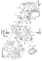
- FIG.2 is an exploded perspective view for explaining an overall actuation around three axes of the joint structure of a robot according to the embodiment of the present invention.
- FIG.3 is a partially enlarged perspective view, which is looked from a lower-side in FIG.1 and which is used for the explanation of a longitudinal swing motion of the joint structure of the robot according to the embodiment of the present invention.
- FIG.4 is a partially enlarged perspective view, which is looked from an upper-side in FIG.1 and which is used for the explanation of the lateral swing motion of the joint structure of the robot according to the embodiment of the present invention.
- FIG.5A is a front view of a wrist for explaining the longitudinal swing motion of the joint structure of the robot according to the embodiment of the present invention.
- FIG.5B is a front view of a wrist for explaining the longitudinal swing motion of the joint structure of the robot according to the embodiment of the present invention.
- FIG.5C is a front view of a wrist for explaining the longitudinal swing motion of the joint structure of the robot according to the embodiment of the present invention.
- FIG.5D is a plane view of a wrist for explaining the lateral swing motion of the joint structure of the robot according to the embodiment of the present invention.
- FIG.5E is a plane view of a wrist for explaining the lateral swing motion of the joint structure of the robot according to the embodiment of the present invention.
- FIG.5F is a plane view of a wrist for explaining the lateral swing motion of the joint structure of the robot according to the embodiment of the present invention.
- FIG.6 is a partially enlarged perspective view for explaining the rotary motion of the joint structure of the robot according to the embodiment of the present invention.
- FIG.7 is an explanatory view for explaining the installation of the movable cover attached to the joint of the joint structure of the robot according to the embodiment of the present invention.
- FIG.8 is an explanatory view for explaining the constitution of the movable cover attached to the joint of the joint structure of the robot according to the embodiment of the present invention.
- Next, the embodiment of the present invention will be explained with reference to attached drawings. Here, in the drawings, a part of the constituents, e.g. an arm cover and etc, may be omitted for convenience of the explanation.
- In the present embodiment, the explanation of the joint structure of a robot according to the present invention will be carried out using the joint structure applied for a wrist of a humanoid-type robot as an example.
- However, the present invention is not limited to the following embodiments, and the joint structure may be applied for an ankle of a humanoid-type robot or for a connection part of a link in a robot of industrial use.
- In the following explanation, the direction of a finger tip in FIG.1 is denoted as fingertip side, the direction of an elbow is denoted as elbow side, the direction of upper side in FIG.1 is denoted as upper side, the direction of lower side in FIG.1 is denoted as lower side, the direction of front side from page in FIG.1 is denoted as left side, and the direction of back-side in FIG.1 is denoted as right-side.
- Firstly, the overall constitution of the joint structure of the robot according to this embodiment will be explained with reference to FIG.1.
- FIG.1 is an explanatory view for explaining the joint structure of the robot according to the present embodiment. In FIG.1, a
hand 51 which is an assembly of parts constituting a hand, awrist 52 which joins thehand 51 and anarm 53 while allowing the turn around thewrist 52, thearm 53 which serves as an robot-link, and anelbow 54, are indicated. - As shown in FIG.1, the joint structure of the robot according to the present embodiment is a joint structure of a
wrist 52 in the humanoid-type robot. This joint structure is composed of afirst motor 10 for a longitudinal swing motion of thehand 51, asecond motor 20 for a lateral swing motion of thehand 51, athird motor 30 for a rotary motion of thehand 51, and amovable cover 40 covering the joint of thewrist 52. - In other words, the
first motor 10 swings thehand 51 around a first axis orthogonal to the central axis of thearm 53. Thesecond motor 20 swings thehand 51 around a second axis, which is orthogonal to the first axis and cross the first axis on the center axis of thearm 53. Thethird motor 30 rotates thehand 51 around the central axis of thearm 53. Here, the central axis of thearm 53 is an axis which passes the center of thearm 53 and elongates in a longitudinal direction of thearm 53. In the following explanation, the central axis of thearm 53 is also called as the rotation axis of a rotary motion of the hand - Firstly, the layout of the motor which provides a driving force to the joint structure of a robot will be explained.
- The
first motor 10 and thesecond motor 20 are disposed in parallel to each other on both sides (left-and-right side) with respect to the central axis of thearm 53. Thefirst motor 10 and thesecond motor 20 are disposed so that the output axis of each of thefirst motor 10 and thesecond motor 20 is directed in an ups-and-downs direction. In this embodiment, thefirst motor 10 and thesecond motor 20 are respectively positioned in the right side and left side of the central axis of thearm 53. - Furthermore, the
third motor 30 is positioned backward (in an elbow-side) of thefirst motor 10 and thesecond motor 20, and an output shaft of thethird motor 30 is disposed in a right side with respect to the rotation axis, which is an rotation axis of a rotary motion of the hand. - In the present embodiment, for explaining the motion of the joint structure of the wrist, the indication of other components, e.g. a control mechanism and a harness etc, is omitted in this figure.
- As shown in FIG.2, the joint structure of the wrist according to this embodiment includes a longitudinal
rotary unit 1 for a longitudinal swing motion, a lateralrotary unit 2 for a lateral swing motion, amotor mount 3 which connects with the longitudinalrotary unit 1 and lateralrotary unit 2 and enables the rotary motion of the longitudinalrotary unit 1 and lateralrotary unit 2, and a driven pulley 35 (see FIG. 1). - To be more precise, the longitudinal
rotary unit 1 and lateralrotary unit 2 are disposed at a fingertip side of thearm 53. Thefirst motor 10 andsecond motor 20, which are aligned along a left-and-right direction on themotor mount 3, are disposed behind the longitudinalrotary unit 1 and lateralrotary unit 2. As shown in FIG. 1, themotor mount 3 is fixed to the drivenpulley 35, which is supported by arib 36 while allowing the rotation thereof. - As shown in FIG. 2, the longitudinal
rotary unit 1 includes abase plate 1a having a round-shaped through hole at the center thereof, side-brackets 1b1 and 1b2 disposed on both sides of thebase plate 1a, anarm 1c which elongates in an obliquely downward direction from the bottom side of thebase plate 1a, and a connection pin 4 which serves as a hinge of thearm 1c. - The lateral
rotary unit 2 is a rectangle-shaped member formed by connecting both ends of the approximate U-shaped member with a left-side frame 2c1. Here, the approximate U-shaped member comprises an upper-side frame 2a, a lower-side link 2b, and a right-side frame 2c2 and is formed into an integral shape by these members. An opening at the center of the lateralrotary unit 2 is adapted to pass or dispose therein supplementary parts, i.e. a harness etc. - A
center hole side frame 2a and the lower-side link 2b, respectively. Alateral rotation axis 6 and 6' , which serves as a rotation support of the lateral swing motion, is inserted to eachcenter hole longitudinal rotation axis 5 and 5', which serves as a rotation support of the longitudinal swing motion and elongates inward, is provided on the right-side frame 2c2 and the left-side frame 2c1, respectively. Here, the line connecting lateral rotation axes 6 and 6' corresponds to the above-described second axis, and the line connectinglongitudinal rotation axes 5 and 5' corresponds to the above-described first axis. - A through
hole 2e is provided on thelongitudinal rotation axis 5 of the left-side frame 2c1, and aharness guide 5a is inserted into this throughhole 2e. - Here, a longitudinal
rotary unit 1 is pivotably supported by the left-side frame 2c1 and the right-side frame 2c2. - That is, the longitudinal
rotary unit 1 is supported by thelongitudinal rotation axis 5 and 5', which are formed on the left-side frame 2c1 and the right-side frame 2c2, respectively, through the bearing 1d1 and 1d2. Thereby, the longitudinalrotary unit 1 is allowed to turn around thelongitudinal rotation axis 5 and 5' and provide the longitudinal swing motion. - The
motor mount 3 comprises anupper flange 3a, alower flange 3b, and aconnection plate 3c. Theupper flange 3a andlower flange 3b are arranged in parallel, and are connected each other by theconnection plate 3c. Themotor mount 3 is formed into an integral shape having an approximate U-like shape in a side-viewing from theupper flange 3a, thelower flange 3b, and theconnection plate 3c. - A
central hole upper flange 3a and thelower flange 3b, respectively. Thecentral hole upper flange 3a andlower flange 3b, respectively. Thebearing lateral rotation axis 6 and 6', is provided within thecentral hole lateral rotation axis 6 is directly screwed into the upper-side frame 2a, and the lateral rotation axis 6' is fixed to the lower-side link 2b using a screw 6' '. - The
second motor mount 3a' is formed on the rear-end (an elbow-side) of theupper flange 3a so that thesecond motor mount 3a' extends into a left side. Thefirst motor mount 3b' is formed on the rear-end (an elbow-side) of thelower flange 3b so that thefirst motor mount 3b' extends into a right side. That is, thesecond motor mount 3a' and thefirst motor mount 3b' extend in an opposing direction each other. Thesecond motor 20 is disposed on thesecond motor mount 3a' usingbolts 8 so that areduction unit 21 is positioned in an upper-side. Thefirst motor 10 is disposed on thefirst motor mount 3b' so that a reduction unit 11 (not shown) is positioned in a lower-side. - As described above, since the longitudinal
rotary unit 1 is joined to the left-side frame 2c1 and right-side frame 2c2 of the lateralrotary unit 2 so that the rotation around thelongitudinal rotation axis 5 and 5' is allowed, the longitudinal swing motion of the longitudinalrotary unit 1 is enabled. - Additionally, since the lateral
rotary unit 2 is joined to themotor mount 3 so that the rotation around thelateral rotation axis 6 and 6' is allowed, the lateral swing motion of the lateralrotary unit 2 is enabled. - As mentioned above, furthermore, since the
motor mount 3 is fixed to the drivenpulley 35, which is rotatably supported by the rib 36 (see FIG.1), the rotary motion of themotor mount 3 in accordance with the rotation of themotor mount 3 is enabled. - Next, the explanation about the mechanism for controlling each of the above explained motion (the longitudinal swing motion, the lateral swing motion, and the rotary motion) will be carried out.
- As shown in FIG.3, the mechanism for controlling the swing in a height direction (longitudinal swing motion) includes the
first motor 10 as power source, aswing lever 12 being connected to thereduction unit 11 of thefirst motor 10, a spherical joint 13 being connected to theswing lever 12, and the longitudinalrotary unit 1 being connected to the spherical joint 13. Thefirst motor 10 is positioned on a right side with respect to the central axis of thearm 53 and is disposed on themotor mount 3 so that thereduction unit 11, which connects with an output shaft of thefirst motor 10, is in a lower side. - The
swing lever 12 connects with thereduction unit 11 of thefirst motor 10 at the base-end 12a thereof and provides an integral body together with thereduction unit 11. Additionally, theswing lever 12 rotatably connects with one end of the spherical joint 13 through aspherical bearing 13a having a self-aligning function. The other end of the spherical joint 13 rotatably connects with the connection pin 4 disposed on thearm 1c of the longitudinalrotary unit 1 though thespherical bearing 13b. - In this embodiment, as shown in FIG.5A to FIG.5C, the rotation (torque) of the output shaft of the
first motor 10 is transmitted to thereduction unit 11 and is changed to the swing motion (reciprocating motion) of theswing lever 12. Then, this swing motion is transmitted to the longitudinalrotary unit 1 through the spherical joint 13, and turns the longitudinalrotary unit 1 around thelongitudinal rotation axis 5 and 5' . Here, since thehand 51 is fixed to the longitudinalrotary unit 1, the longitudinal swing motion of thehand 51 can be achieved in accordance with the turn of the longitudinalrotary unit 1. - In the present embodiment, additionally, the spherical joint is used. But, a universal joint etc can be used instead of the spherical joint.
- As shown in FIG.4, on the other hand, the mechanism for controlling the swing in a sideward direction (lateral swing motion) includes a
second motor 20 as power source, aswing lever 22 which is connected to an outputs-side of thereduction unit 21 of thesecond motor 20 and provides an integral body, arod 23 which rotatably connects with thisswing lever 22, and the lateralrotary unit 2 which rotatably connects with therod 23. Thesecond motor 20 is positioned on a left side with respect to the central axis of thearm 53 and is disposed on themotor mount 3 so that the output side of thereduction unit 21, which connects with an output shaft of thesecond motor 20, is in an upper side. - The
swing lever 22 is fixed to the output shaft of thereduction unit 21 of thesecond motor 20 at a base-end 22a thereof, and connects with oneend 23a of therod 23 attip side 22b thereof. Theother end 23b of therod 23 is rotatably connected to the left-side frame 2c1 of the lateralrotary unit 2. - In this embodiment, as shown in FIG.5D to FIG.5F, the rotation (torque) of the output shaft of the
second motor 20 is transmitted to thereduction unit 21 and is changed to the swing motion (reciprocating motion) of theswing lever 22. Then, this swing motion is transmitted to the lateralrotary unit 2 through therod 23, and turns the lateralrotary unit 2 around thelateral rotation axis 6 and 6'. - Here, since the
hand 51 connects with the lateralrotary unit 2 through the longitudinalrotary unit 1, the lateral swing motion of thehand 51 can be achieved in accordance with the turn of the lateralrotary unit 2. - In the present embodiment, additionally, the mechanism for controlling the swing in a height direction (longitudinal swing motion) and the swing in a sideward direction (lateral swing motion) is represented by a link mechanism using a lever and a joint. However, present invention is not limited to this embodiment, and may be represented by using various types of tools, e.g. a gear, a belt or etc.
- As shown in FIG. 6, the rotary mechanism includes a
third motor 30 as power source, an output pulley (motor side pulley) 33 fixed to the output shaft of areduction unit 32, abelt 34, a drivenpulley 35, and arib 36. - The
third motor 30, for example, is disposed so that the output shaft thereof is in a right side with respect to the rotation axis of the rotary motion (rotation axis of the driven pulley 35). Additionally, the output shaft of thethird motor 30 is disposed in parallel to the rotation axis of the rotary motion. - The
reduction unit 32 is joined to the output shaft of thethird motor 30 and provides an integral body together with thethird motor 30, and theoutput pulley 33 is fixed to thisreduction unit 32. In this embodiment, thebelt 34 is put around theoutput pulley 33 and drivenpulley 35 so that the rotation of theoutput pulley 33 is transmitted to the drivenpulley 35. In this embodiment, therefore, the drivenpulley 35 is rotated in accordance with the rotation of theoutput pulley 33. - The driven
pulley 35 is a cylindrical shaped member having thehollow section 35a at an inside thereof. A flange 35b1 and flange 35b2 are provided at ends in a fingertip-side and elbow-side of the drivenpulley 35, respectively, so as to guide the rotation of thebelt 34 while keeping thebelt 34 between flanges 35b1 and 35b2. The drivenpulley 35 is rotatably supported by therib 36, which is disposed along an orthogonal direction with respect to thearm 53, through a bearing etc. - Thereby, the rotation (torque) of the
third motor 30 is reduced by thereduction unit 32 and is transmitted to the drivenpulley 35 from theoutput pulley 33 using thebelt 34 for rotating the drivenpulley 35. Here, themotor mount 3 is fixed to the fingertip side's end of the drivenpulley 35. Thus, the rotary motion of thehand 51 connected to themotor mount 3 through the lateralrotary unit 2 and longitudinalrotary unit 1 can be achieved, by rotating themotor mount 3 using the drivenpulley 35. - The joint structure of the robot of the present embodiment, as shown in FIG. 1, includes a
wrist cover 41 being fixed to thehand 51, and anarm cover 42 as the outer shell of thearm 53, and amovable cover 40 disposed between thewrist cover 41 and thearm cover 42 as if connecting thewrist cover 41 and thearm cover 42. - The
movable cover 40, as shown in FIG.7, is attached to the outside periphery of thewrist cover 41. In this embodiment, for example, themovable cover 40 is held on thewrist cover 41 usinglatches 41a, e.g. 6 latches, which are provided around thewrist cover 41. - The
movable cover 40 has a cylindrical shape with short length so that part of the outside periphery of thewrist cover 41 is covered with themovable cover 40 , and a curvature is formed along a fore-and-rear direction of themovable cover 40. In this embodiment, the curvature in the elbow side of themovable cover 40 is large, and the curvature in the fingertip side of themovable cover 40 is slightly smaller than that in the elbow side. In FIG.7, only left side with respect to the central axis of the arm 53 (see FIG.1) is indicated. But the constitutions in a right side are the same constitution as that in a left side. - In this embodiment, as shown in FIG. 8, the
movable cover 40 comprises amovable cover 401 and amovable cover 402. Themovable cover 401 and themovable cover 402 are positioned in an upper-side and a lower-side, respectively, and are joined each other using ascrew 44 to provide an integral body. -
Flat areas movable covers 401 and themovable cover 402, respectively. The position where theflat area 40d is provided is an outside in an elbow side'speriphery 40c of themovable cover 40.Flat areas screw 44, and are positioned at opposite sides across the joint surface betweenmovable covers -
Spring stopper movable cover spring stopper 40b is provided is an inside of the elbow side'speriphery 40c of themovable cover 40. Thespring stopper 40b has a triangular shape in a front viewing, and protrudes in a fingertip side from the inside surface of theflat area 40d. A space 40b1 storing therein atorsion coil spring 43 is formed on thespring stopper 40b. - In the present embodiment, the
torsion coil spring 43 is adopted as an example of the "elastic member", and themovable cover 40 is rotatably fixed to thewrist cover 41 through thetorsion coil spring 43. - The
torsion coil spring 43, as shown in FIG.8, comprises acenter section 43a and anend section 43b, and thecenter section 43a is spiraled to provide a coil-like shape. In this embodiment, two torsion coil springs 43 are used, and eachend section 43b of two torsion coil springs 43 protrudes from thecenter section 43a so as to figure a v-shape in a side viewing fromend sections 43a. - The
center section 43a of eachtorsion coil spring 43 is fitted on aknob 41b formed on thewrist cover 41 to support thetorsion coil spring 43 by theknob 41b. Each curledend torsion coil spring 43 is pushed against theflat area 40d of themovable cover 40 and applies a force directing from a fingertip side to an elbow side. - In this embodiment, the
torsion coil spring 43 causes elastic force narrowing the angle θ betweenend sections flat areas end movable cover 40 is held on thewrist cover 41 by the contact between the inner periphery of themovable cover 40 andlatches 41a formed on thewrist cover 41. - In this embodiment, additionally, the
torsion coil spring 43 is adopted. But, a helical compression spring and an elastic string etc may be adoptable instead of the torsion coil spring. In this embodiment, furthermore, themovable cover 40 is provided on the side of the hand 51 (assembly) using the elastic member (torsion coil spring 43) . But, themovable cover 40 may be provided on the side of the arm 53 (robot link) or may be provided on the both sides of thehand 51 and thearm 53. - The function of the joint structure of the wrist of the robot will be explained with reference to FIG.1 and FIG.2.
- In this embodiment, the rotation mechanism comprising the longitudinal
rotary unit 1, the lateralrotary unit 2, and themotor mount 3 being connected to the drivenpulley 35 is provided. Thereby, the joint structure of this embodiment provides three degree of freedom, e.g. a longitudinal swing motion, a lateral swing motion, and a rotary motion, by thefirst motor 10, thesecond motor 20, and thethird motor 30, respectively. - Additionally, the
first motor 10 and thesecond motor 20 are disposed linearly along a left-and-right direction of thearm 53 so that the output axis of each of thefirst motor 10 and thesecond motor 20 is directed in an ups-and-downs direction. - Thereby, since the
first motor 10 and thesecond motor 20 are disposed linearly along a left-and-right direction so that the output axis of each of thefirst motor 10 and thesecond motor 20 is directed in an ups-and-downs direction, an inertia moment around theelbow 54 can be reduced. - In this invention, since the
third motor 30 is disposed so that thethird motor 30 is shifted from the central axis of the rotary motion, a space is ensured in the vicinity of the central axis of the rotary motion. Thereby, the provision of the harness in the vicinity of the central axis of the rotary motion is enabled. - To be more precise, the harness can be passed from the
elbow 54 to thewrist 52 through the vicinity of thethird motor 30, ahollow section 35a (see FIG.6) formed at the inside-periphery of the drivenpulley 35, the clearance between thefirst motor 10 and thesecond motor 20, and the openings formed at the center of each of the longitudinalrotary unit 1 and the lateralrotary unit 2. - In this embodiment, as described above, the harness can be passed near the central axis of the longitudinal swing motion, the lateral swing motion, and the rotary motion. Thereby, the restriction in an actuation angle of the hand due to the harness can be minimized, and the occurrence of the breakage of the harness can be prevented.
- In the present embodiment, additionally, a through
hole 2e is provided on the left-side frame 2c1 of the lateralrotary unit 2 to ensure the passage for the harness that is used when installing the harness to the tip of the hand. - Additionally, the function of the
movable cover 40 will be explained with reference to FIG.7 and FIG.8. - In this embodiment, the
flat area 40d is pushed to an elbow side from a fingertip side, by the curledend 43c of thetorsion coil spring 43. Also, latches 41a formed on thewrist cover 41 are contactable with the inner circumference of themovable cover 40. Thereby, themovable cover 40 is held on thewrist cover 41 while allowing the rotation around thewrist cover 41 of themovable cover 40. - Therefore, the
movable cover 40 begins to rotate in accordance with the turn of thehand 51. In this case, the turn of thehand 51 is not disturbed even if themovable cover 40 contacts with internal parts, e.g. motor etc. This is because the torque of thehand 51 exceeds the elastic force given by thetorsion coil spring 43 and enables the further turn of thehand 51 from the position, where the turn of thehand 51 is disturbed due to the contact with internal parts of thehand 51. - Thereby, the occurrence of the inhibition of the turn of the
hand 51 due to the contact with themovable cover 40 can be prevented. - When the direction of the turn of the wrist is reversed, on the other hand, since the
movable cover 40 moves in a direction apart from internal parts, themovable cover 40 can be backed to the predetermined position by the elastic force of thetorsion coil spring 43. - In the case of the rotary motion, furthermore, the
movable cover 40 begins to rotate in accordance with the rotation of thehand 51. In this case, the rotation of thehand 51 is not disturbed even if themovable cover 40 contacts with internal parts and inhibits the rotation of thehand 51. This is because the torque of thehand 51 exceeds the elastic force given by thetorsion coil spring 43 and enables further rotation of thehand 51 from the position, where the rotation of thehand 51 is disturbed due to the contact with the internal parts of thehand 51. - Thereby, the occurrence of the inhibition of the rotation of the
hand 51 due to the contact with themovable cover 40 can be prevented even in the case of the rotary motion, and themovable cover 40 can be backed to the predetermined position when the direction of the rotation of thehand 51 is reversed. - Although there have been disclosed what are the patent embodiment of the invention, it will be understood by person skilled in the art that variations and modifications may be made thereto without departing from the scope of the invention, which is indicated by the appended claims.
- In the above described embodiment, for example, the first motor and the second motor are disposed at left-and-right of the central axis of the arm. The first motor and the second motor may be disposed with a shift in a direction along the central axis of the arm so that the output axis of each of the first motor and the second motor becomes parallel each other. In this case, the amplitude of the inertia moment can be controlled by shifting the weight of the motor to an elbow side from a fingertip side.
- In the present embodiment, the third motor is disposed so that the output shaft thereof becomes parallel to the central axis of the rotary motion. The third motor may be disposed so that the output shaft thereof becomes orthogonal to the central axis of the rotary motion. In this case, the length of the arm can be shortened furthermore, and the amplitude of the inertia moment can be controllable.
- In the above described embodiment, additionally, the rotary motion of the wrist of the humanoid type robot has been explained for explaining the present invention's joint structure. But, this invention is not limited to this, and can be applied for a rotator rotating continuously, e.g. the rotation of a drill, when applying this invention to a robot for an industrial use.
- In the present embodiment, the third motor is disposed behind the first motor and the second motor. But the third motor may be disposed in front of the first motor and second motor. In this case, inertia moment around the elbow can also be controllable.
- The inertia moment can be controllable by adjusting the position of each of the motors without changing the positional relation between respective motors. In the present invention, the appropriate modification may be acceptable in accordance with the use and the conditions. Thereby, the setting of inertia moment and weight balance can be enabled.
Claims (8)
- A joint structure of a robot for actuating an assembly being connected to a robot link, the joint structure comprising:a first motor for causing the assembly a longitudinal swing motion with respect to the robot link; anda second motor for causing the assembly a lateral swing motion with respect to the robot link, whereinthe first motor and the second motor are disposed so that the output shaft of the first motor and the output shaft of the second motor are in parallel with each other and are orthogonal to the robot link.
- A joint structure of a robot according to claim 1 further comprising:a third motor for causing the assembly a rotary motion with respect to the robot link, whereinthe output shaft of the third motor is shifted by a predetermined amount with respect to the central axis of the rotary motion.
- A joint structure of a robot according to claim 1 or claim 2 further comprising:a movable cover being rotatable with respect to at least one of the assembly and the robot link, andan elastic member generating a force between the movable cover and at least one of the assembly and the robot link, and placing the movable cover at a predetermined position.
- A joint structure of a robot according to claim 1 or claim 2 further comprising:a first rotary unit being connected to the assembly;a second rotary unit supporting the first rotary unit while allowing the rotation around a first axis of the first rotary unit; anda base supporting the second rotary unit while allowing the rotation around a second axis orthogonal to the first axis of the second rotary unit, whereinthe first motor and the second motor are disposed on the base.
- A joint structure of a robot according to claim 4 further comprising:a first swing lever which is connected to an output shaft of the first motor, and changes the rotation of the output shaft of the first motor into a reciprocating motion;a joint which is connected to the first swing lever and the first rotary unit, and transfers the reciprocating motion to the first swing lever to rotate the first rotary unit around the first axis;a second swing lever which is connected to an output shaft of the second motor, and changes a rotary motion of the output shaft of the second motor into a reciprocating motion; anda rod which is connected to the second swing lever and the second rotary unit, and transfers the reciprocating motion to the second rotary unit to rotate the second rotary unit around the second axis.
- A joint structure of a robot according to claim 4 further comprising:a motor side pulley which is connected to an output shaft of the third motor;a driven pulley which is connected to the base and rotates the base around the central axis of the rotary motion; anda belt which transfers the rotation of the motor side pulley to the driven pulley.
- A joint structure of a robot according to claim 5 further comprising:a motor side pulley which is connected to an output shaft of the third motor;a driven pulley which is connected to the base and rotates the base around the central axis of the rotary motion; anda belt which transfers the rotation of the motor side pulley to the driven pulley.
- A joint structure of a robot according to claim 3, wherein
a contact face to which the elastic member is contactable is formed on the movable cover, and
a stopper, which contacts with the elastic member to control the range of the rotation around the central axis of the rotary motion of the movable cover, is provided at an inside periphery of the movable cover.
Applications Claiming Priority (2)
| Application Number | Priority Date | Filing Date | Title |
|---|---|---|---|
| JP2004362065A JP4589712B2 (en) | 2004-12-14 | 2004-12-14 | Robot joint structure |
| PCT/JP2005/020932 WO2006064625A1 (en) | 2004-12-14 | 2005-11-15 | Joint structure for robot |
Publications (3)
| Publication Number | Publication Date |
|---|---|
| EP1829651A1 true EP1829651A1 (en) | 2007-09-05 |
| EP1829651A4 EP1829651A4 (en) | 2008-02-20 |
| EP1829651B1 EP1829651B1 (en) | 2010-12-15 |
Family
ID=36587688
Family Applications (1)
| Application Number | Title | Priority Date | Filing Date |
|---|---|---|---|
| EP05807077A Expired - Fee Related EP1829651B1 (en) | 2004-12-14 | 2005-11-15 | Joint structure of a robot |
Country Status (6)
| Country | Link |
|---|---|
| US (1) | US7938038B2 (en) |
| EP (1) | EP1829651B1 (en) |
| JP (1) | JP4589712B2 (en) |
| KR (1) | KR100806966B1 (en) |
| DE (1) | DE602005025400D1 (en) |
| WO (1) | WO2006064625A1 (en) |
Cited By (1)
| Publication number | Priority date | Publication date | Assignee | Title |
|---|---|---|---|---|
| EP3385571A4 (en) * | 2015-12-03 | 2019-08-07 | Kawasaki Jukogyo Kabushiki Kaisha | Two-degree-of-freedom drive mechanism |
Families Citing this family (26)
| Publication number | Priority date | Publication date | Assignee | Title |
|---|---|---|---|---|
| US20090071282A1 (en) * | 2006-02-01 | 2009-03-19 | Honda Motor Co., Ltd. | Joint Structure of Robot |
| KR100777115B1 (en) | 2006-10-26 | 2007-11-19 | 강삼태 | Arm joint apparatus for robot |
| KR101067688B1 (en) * | 2007-10-16 | 2011-09-27 | 주식회사 로보멕 | Joint apparatus with multi-degree of freedom |
| WO2009051393A2 (en) * | 2007-10-16 | 2009-04-23 | Robomech Co., Ltd. | Joint apparatus with multi-degree of freedom |
| KR100889085B1 (en) | 2007-10-24 | 2009-03-17 | 삼성중공업 주식회사 | Tracking apparatus for a curved plate |
| FR2930905B1 (en) * | 2008-05-09 | 2010-10-01 | Bia | ANKLE FOR HUMANOIDE ROBOT |
| KR101474772B1 (en) * | 2008-12-11 | 2014-12-22 | 삼성전자 주식회사 | Robot |
| KR101117253B1 (en) * | 2009-06-25 | 2012-03-15 | 고려대학교 산학협력단 | Robot Arm |
| US8291788B2 (en) * | 2009-09-22 | 2012-10-23 | GM Global Technology Operations LLC | Rotary series elastic actuator |
| TWI400150B (en) * | 2010-10-29 | 2013-07-01 | Hon Hai Prec Ind Co Ltd | Robotic joint |
| CN102452078B (en) * | 2010-11-01 | 2014-04-23 | 鸿富锦精密工业(深圳)有限公司 | Robot joint |
| KR101494491B1 (en) * | 2011-08-17 | 2015-02-23 | 고려대학교 산학협력단 | Robot Arm |
| JP5722747B2 (en) * | 2011-10-24 | 2015-05-27 | Thk株式会社 | Robot joint structure and robot incorporating this joint structure |
| KR101324988B1 (en) * | 2012-06-20 | 2013-11-04 | 이춘우 | Robot and manipulator provided with ball joint |
| US9605952B2 (en) | 2012-03-08 | 2017-03-28 | Quality Manufacturing Inc. | Touch sensitive robotic gripper |
| CN107009374A (en) | 2012-03-08 | 2017-08-04 | 品质制造有限公司 | Touch sensitive robot's handgrip |
| DE102012208448A1 (en) * | 2012-05-21 | 2013-11-21 | Kuka Roboter Gmbh | Industrial robot with drives in a base housing |
| JPWO2013175554A1 (en) * | 2012-05-21 | 2016-01-12 | 株式会社安川電機 | Robot and robot system |
| JP6767093B2 (en) * | 2015-03-12 | 2020-10-14 | 株式会社岩田鉄工所 | Multi-finger hand device |
| US10718359B2 (en) | 2015-08-21 | 2020-07-21 | Quality Manufacturing Inc. | Devices and systems for producing rotational actuation |
| KR101766576B1 (en) * | 2016-01-14 | 2017-08-09 | 한양대학교 산학협력단 | Driving apparatus having multi-degrees of freedom |
| CN106737823A (en) * | 2016-12-30 | 2017-05-31 | 深圳市优必选科技有限公司 | Articulation structure and robot |
| JP7110781B2 (en) * | 2018-07-19 | 2022-08-02 | 株式会社デンソーウェーブ | robot jacket |
| US11254015B2 (en) | 2019-09-24 | 2022-02-22 | Thermo Crs Ltd. | Multi-axis gripper for lab automation robot |
| EP3988261B1 (en) | 2020-10-26 | 2023-02-01 | Siemens Aktiengesellschaft | Gripper for a robot |
| CN113910289B (en) * | 2021-09-02 | 2023-09-12 | 宁波巾山微型精密机器人有限公司 | Ring joint |
Citations (6)
| Publication number | Priority date | Publication date | Assignee | Title |
|---|---|---|---|---|
| EP0180558A2 (en) * | 1984-05-18 | 1986-05-07 | Asea Ab | An industrial robot having two gimbal-ring type arranged swinging axes |
| EP0200105A1 (en) * | 1985-04-22 | 1986-11-05 | Kabushiki Kaisha Toshiba | Industrial robot |
| US4805477A (en) * | 1987-10-22 | 1989-02-21 | Gmf Robotics Corporation | Multiple joint robot part |
| US5255571A (en) * | 1992-06-25 | 1993-10-26 | United Parcel Service Of America, Inc. | Three degree of freedom actuator system |
| EP0658405A1 (en) * | 1993-12-17 | 1995-06-21 | COMAU S.p.A. | Industrial robot with integrated reduction gear units |
| US5765443A (en) * | 1996-07-24 | 1998-06-16 | Fujitsu Ltd | Joint mechanism and robot having the joint mechanism |
Family Cites Families (8)
| Publication number | Priority date | Publication date | Assignee | Title |
|---|---|---|---|---|
| US765443A (en) * | 1902-10-09 | 1904-07-19 | Charles L Seabury | Water-tube boiler. |
| FR2462607A2 (en) * | 1978-09-20 | 1981-02-13 | Ass Ouvriers Instr Precision | ARTICULATION FOR A MANIPULATOR ARM |
| JPS58126091A (en) * | 1982-01-16 | 1983-07-27 | 株式会社明電舎 | Power manipulator |
| JPH0957680A (en) * | 1995-08-18 | 1997-03-04 | Tokico Ltd | Industrial robot |
| US5797900A (en) * | 1996-05-20 | 1998-08-25 | Intuitive Surgical, Inc. | Wrist mechanism for surgical instrument for performing minimally invasive surgery with enhanced dexterity and sensitivity |
| US6244644B1 (en) * | 1999-01-25 | 2001-06-12 | The United States Of America As Represented By The Administrator Of The National Aeronautics And Space Administration | Compact dexterous robotic hand |
| JP2003170381A (en) * | 2001-11-30 | 2003-06-17 | Seiko Epson Corp | Operating device |
| JP4236900B2 (en) * | 2002-10-22 | 2009-03-11 | 本田技研工業株式会社 | Robot joint structure |
-
2004
- 2004-12-14 JP JP2004362065A patent/JP4589712B2/en not_active Expired - Fee Related
-
2005
- 2005-11-15 US US10/585,000 patent/US7938038B2/en active Active
- 2005-11-15 DE DE602005025400T patent/DE602005025400D1/en active Active
- 2005-11-15 EP EP05807077A patent/EP1829651B1/en not_active Expired - Fee Related
- 2005-11-15 WO PCT/JP2005/020932 patent/WO2006064625A1/en active Application Filing
- 2005-11-15 KR KR1020067013374A patent/KR100806966B1/en active IP Right Grant
Patent Citations (6)
| Publication number | Priority date | Publication date | Assignee | Title |
|---|---|---|---|---|
| EP0180558A2 (en) * | 1984-05-18 | 1986-05-07 | Asea Ab | An industrial robot having two gimbal-ring type arranged swinging axes |
| EP0200105A1 (en) * | 1985-04-22 | 1986-11-05 | Kabushiki Kaisha Toshiba | Industrial robot |
| US4805477A (en) * | 1987-10-22 | 1989-02-21 | Gmf Robotics Corporation | Multiple joint robot part |
| US5255571A (en) * | 1992-06-25 | 1993-10-26 | United Parcel Service Of America, Inc. | Three degree of freedom actuator system |
| EP0658405A1 (en) * | 1993-12-17 | 1995-06-21 | COMAU S.p.A. | Industrial robot with integrated reduction gear units |
| US5765443A (en) * | 1996-07-24 | 1998-06-16 | Fujitsu Ltd | Joint mechanism and robot having the joint mechanism |
Non-Patent Citations (1)
| Title |
|---|
| See also references of WO2006064625A1 * |
Cited By (2)
| Publication number | Priority date | Publication date | Assignee | Title |
|---|---|---|---|---|
| EP3385571A4 (en) * | 2015-12-03 | 2019-08-07 | Kawasaki Jukogyo Kabushiki Kaisha | Two-degree-of-freedom drive mechanism |
| US10828787B2 (en) | 2015-12-03 | 2020-11-10 | Kawasaki Jukogyo Kabushiki Kaisha | Drive mechanism of two degrees of freedom |
Also Published As
| Publication number | Publication date |
|---|---|
| EP1829651B1 (en) | 2010-12-15 |
| US7938038B2 (en) | 2011-05-10 |
| DE602005025400D1 (en) | 2011-01-27 |
| US20090173177A1 (en) | 2009-07-09 |
| KR100806966B1 (en) | 2008-02-22 |
| EP1829651A4 (en) | 2008-02-20 |
| KR20070059003A (en) | 2007-06-11 |
| JP2006167847A (en) | 2006-06-29 |
| WO2006064625A1 (en) | 2006-06-22 |
| JP4589712B2 (en) | 2010-12-01 |
Similar Documents
| Publication | Publication Date | Title |
|---|---|---|
| EP1829651B1 (en) | Joint structure of a robot | |
| US8307732B2 (en) | Parallel link robot | |
| KR101631538B1 (en) | Actuator for robot and Humanoid robot comprising thereof | |
| KR100888078B1 (en) | Joint structure of robot | |
| EP1457294B1 (en) | Multi-finger hand device | |
| KR101248627B1 (en) | Industrial robot | |
| CN110311344B (en) | Cable clamp and robot | |
| KR101462250B1 (en) | Robotic manipulator using rotary drives | |
| EP1207024B1 (en) | Elbow joint of a humanoid robot | |
| JP2003181789A (en) | Mechanical weight compensation apparatus | |
| JP2000040445A (en) | Motor-driven spring operation mechanism for opening/ closing apparatus | |
| US7287869B2 (en) | Vehicle mirror apparatus | |
| JP5440279B2 (en) | Robot vibration control device | |
| JP4236337B2 (en) | Electric mirror device | |
| WO2023242960A1 (en) | Manipulator arm | |
| KR102120791B1 (en) | Forearm Structure of Robot Arm | |
| JPH106271A (en) | Robot and its control method | |
| KR102099772B1 (en) | Gravity compensation device capable of bi-directional compensation | |
| EP3196508A1 (en) | Power transmission roller | |
| JP6941790B1 (en) | Joint device | |
| CN207962525U (en) | Illumination and/or signal indicating device and motor vehicles | |
| JP2024002358A (en) | industrial robot | |
| JPH10180456A (en) | Movable joint | |
| JPH065262Y2 (en) | Electric remote control mirror | |
| JPH074144Y2 (en) | Stopper mechanism for industrial robot |
Legal Events
| Date | Code | Title | Description |
|---|---|---|---|
| PUAI | Public reference made under article 153(3) epc to a published international application that has entered the european phase |
Free format text: ORIGINAL CODE: 0009012 |
|
| 17P | Request for examination filed |
Effective date: 20060629 |
|
| AK | Designated contracting states |
Kind code of ref document: A1 Designated state(s): DE FR GB |
|
| A4 | Supplementary search report drawn up and despatched |
Effective date: 20080123 |
|
| DAX | Request for extension of the european patent (deleted) | ||
| RBV | Designated contracting states (corrected) |
Designated state(s): DE FR GB |
|
| 17Q | First examination report despatched |
Effective date: 20080508 |
|
| GRAP | Despatch of communication of intention to grant a patent |
Free format text: ORIGINAL CODE: EPIDOSNIGR1 |
|
| GRAS | Grant fee paid |
Free format text: ORIGINAL CODE: EPIDOSNIGR3 |
|
| GRAA | (expected) grant |
Free format text: ORIGINAL CODE: 0009210 |
|
| RIN1 | Information on inventor provided before grant (corrected) |
Inventor name: SUGAWARA, ZENTA,C/O HONDA R & D CO., LTD. Inventor name: SUGIYAMA, KENICHIRO,C/O HONDA R & D CO., LTD. Inventor name: KOKUSHIYOU, MASAYOSHI,C/O HONDA R & D CO., LTD. |
|
| AK | Designated contracting states |
Kind code of ref document: B1 Designated state(s): DE FR GB |
|
| REG | Reference to a national code |
Ref country code: GB Ref legal event code: FG4D |
|
| REF | Corresponds to: |
Ref document number: 602005025400 Country of ref document: DE Date of ref document: 20110127 Kind code of ref document: P |
|
| PLBE | No opposition filed within time limit |
Free format text: ORIGINAL CODE: 0009261 |
|
| STAA | Information on the status of an ep patent application or granted ep patent |
Free format text: STATUS: NO OPPOSITION FILED WITHIN TIME LIMIT |
|
| 26N | No opposition filed |
Effective date: 20110916 |
|
| REG | Reference to a national code |
Ref country code: DE Ref legal event code: R097 Ref document number: 602005025400 Country of ref document: DE Effective date: 20110916 |
|
| GBPC | Gb: european patent ceased through non-payment of renewal fee |
Effective date: 20111115 |
|
| REG | Reference to a national code |
Ref country code: FR Ref legal event code: ST Effective date: 20120731 |
|
| PG25 | Lapsed in a contracting state [announced via postgrant information from national office to epo] |
Ref country code: GB Free format text: LAPSE BECAUSE OF NON-PAYMENT OF DUE FEES Effective date: 20111115 |
|
| PG25 | Lapsed in a contracting state [announced via postgrant information from national office to epo] |
Ref country code: FR Free format text: LAPSE BECAUSE OF NON-PAYMENT OF DUE FEES Effective date: 20111130 |
|
| REG | Reference to a national code |
Ref country code: DE Ref legal event code: R084 Ref document number: 602005025400 Country of ref document: DE |
|
| REG | Reference to a national code |
Ref country code: DE Ref legal event code: R084 Ref document number: 602005025400 Country of ref document: DE Effective date: 20140821 |
|
| PGFP | Annual fee paid to national office [announced via postgrant information from national office to epo] |
Ref country code: DE Payment date: 20191105 Year of fee payment: 15 |
|
| REG | Reference to a national code |
Ref country code: DE Ref legal event code: R119 Ref document number: 602005025400 Country of ref document: DE |
|
| PG25 | Lapsed in a contracting state [announced via postgrant information from national office to epo] |
Ref country code: DE Free format text: LAPSE BECAUSE OF NON-PAYMENT OF DUE FEES Effective date: 20210601 |