EP1829953A1 - Slide material, process for producing the same and apparatus utilizing the slide material - Google Patents
Slide material, process for producing the same and apparatus utilizing the slide material Download PDFInfo
- Publication number
- EP1829953A1 EP1829953A1 EP04822487A EP04822487A EP1829953A1 EP 1829953 A1 EP1829953 A1 EP 1829953A1 EP 04822487 A EP04822487 A EP 04822487A EP 04822487 A EP04822487 A EP 04822487A EP 1829953 A1 EP1829953 A1 EP 1829953A1
- Authority
- EP
- European Patent Office
- Prior art keywords
- sliding material
- wheel
- ball
- molecules
- sliding
- Prior art date
- Legal status (The legal status is an assumption and is not a legal conclusion. Google has not performed a legal analysis and makes no representation as to the accuracy of the status listed.)
- Granted
Links
- 239000000463 material Substances 0.000 title claims abstract description 111
- 238000000034 method Methods 0.000 title description 4
- 239000013078 crystal Substances 0.000 claims abstract description 42
- 239000011229 interlayer Substances 0.000 claims abstract description 30
- 239000010410 layer Substances 0.000 claims abstract description 23
- OKTJSMMVPCPJKN-UHFFFAOYSA-N Carbon Chemical compound [C] OKTJSMMVPCPJKN-UHFFFAOYSA-N 0.000 claims description 32
- 239000007787 solid Substances 0.000 claims description 16
- 238000004519 manufacturing process Methods 0.000 claims description 14
- 229910052799 carbon Inorganic materials 0.000 claims description 9
- 239000000203 mixture Substances 0.000 claims description 9
- 239000012530 fluid Substances 0.000 claims description 8
- 239000002356 single layer Substances 0.000 claims description 8
- 229910002804 graphite Inorganic materials 0.000 description 23
- 239000010439 graphite Substances 0.000 description 23
- 238000004804 winding Methods 0.000 description 23
- 239000000314 lubricant Substances 0.000 description 15
- QAOWNCQODCNURD-UHFFFAOYSA-N Sulfuric acid Chemical compound OS(O)(=O)=O QAOWNCQODCNURD-UHFFFAOYSA-N 0.000 description 12
- 238000005461 lubrication Methods 0.000 description 8
- 239000004593 Epoxy Substances 0.000 description 7
- 239000000853 adhesive Substances 0.000 description 7
- 230000001070 adhesive effect Effects 0.000 description 7
- 239000000758 substrate Substances 0.000 description 7
- GRYLNZFGIOXLOG-UHFFFAOYSA-N Nitric acid Chemical compound O[N+]([O-])=O GRYLNZFGIOXLOG-UHFFFAOYSA-N 0.000 description 6
- 229910052751 metal Inorganic materials 0.000 description 6
- 239000002184 metal Substances 0.000 description 6
- 229910017604 nitric acid Inorganic materials 0.000 description 6
- 239000002120 nanofilm Substances 0.000 description 5
- 238000007747 plating Methods 0.000 description 5
- 239000004575 stone Substances 0.000 description 5
- 229910001369 Brass Inorganic materials 0.000 description 4
- XMWRBQBLMFGWIX-UHFFFAOYSA-N C60 fullerene Chemical class C12=C3C(C4=C56)=C7C8=C5C5=C9C%10=C6C6=C4C1=C1C4=C6C6=C%10C%10=C9C9=C%11C5=C8C5=C8C7=C3C3=C7C2=C1C1=C2C4=C6C4=C%10C6=C9C9=C%11C5=C5C8=C3C3=C7C1=C1C2=C4C6=C2C9=C5C3=C12 XMWRBQBLMFGWIX-UHFFFAOYSA-N 0.000 description 4
- 239000010951 brass Substances 0.000 description 4
- 229910003472 fullerene Inorganic materials 0.000 description 4
- 238000010438 heat treatment Methods 0.000 description 4
- 239000007788 liquid Substances 0.000 description 4
- 239000003921 oil Substances 0.000 description 4
- 229910000975 Carbon steel Inorganic materials 0.000 description 3
- 239000011324 bead Substances 0.000 description 3
- 239000010962 carbon steel Substances 0.000 description 3
- 230000000694 effects Effects 0.000 description 3
- 238000007654 immersion Methods 0.000 description 3
- 230000002687 intercalation Effects 0.000 description 3
- 238000009830 intercalation Methods 0.000 description 3
- -1 polyethylene terephthalate Polymers 0.000 description 3
- 229920006324 polyoxymethylene Polymers 0.000 description 3
- 239000010453 quartz Substances 0.000 description 3
- 229920005989 resin Polymers 0.000 description 3
- 239000011347 resin Substances 0.000 description 3
- 238000005096 rolling process Methods 0.000 description 3
- VYPSYNLAJGMNEJ-UHFFFAOYSA-N silicon dioxide Inorganic materials O=[Si]=O VYPSYNLAJGMNEJ-UHFFFAOYSA-N 0.000 description 3
- PXHVJJICTQNCMI-UHFFFAOYSA-N Nickel Chemical compound [Ni] PXHVJJICTQNCMI-UHFFFAOYSA-N 0.000 description 2
- 229930182556 Polyacetal Natural products 0.000 description 2
- 238000001035 drying Methods 0.000 description 2
- 238000001000 micrograph Methods 0.000 description 2
- 239000002245 particle Substances 0.000 description 2
- 229920000515 polycarbonate Polymers 0.000 description 2
- 239000004417 polycarbonate Substances 0.000 description 2
- 238000000859 sublimation Methods 0.000 description 2
- 230000008022 sublimation Effects 0.000 description 2
- 238000007740 vapor deposition Methods 0.000 description 2
- XLYOFNOQVPJJNP-UHFFFAOYSA-N water Substances O XLYOFNOQVPJJNP-UHFFFAOYSA-N 0.000 description 2
- 229910000838 Al alloy Inorganic materials 0.000 description 1
- IJGRMHOSHXDMSA-UHFFFAOYSA-N Atomic nitrogen Chemical compound N#N IJGRMHOSHXDMSA-UHFFFAOYSA-N 0.000 description 1
- RYGMFSIKBFXOCR-UHFFFAOYSA-N Copper Chemical compound [Cu] RYGMFSIKBFXOCR-UHFFFAOYSA-N 0.000 description 1
- 229910000881 Cu alloy Inorganic materials 0.000 description 1
- 229910000861 Mg alloy Inorganic materials 0.000 description 1
- 229930040373 Paraformaldehyde Natural products 0.000 description 1
- 239000004696 Poly ether ether ketone Substances 0.000 description 1
- 239000004952 Polyamide Substances 0.000 description 1
- 239000004697 Polyetherimide Substances 0.000 description 1
- 239000004734 Polyphenylene sulfide Substances 0.000 description 1
- 239000004793 Polystyrene Substances 0.000 description 1
- 229910000831 Steel Inorganic materials 0.000 description 1
- HCHKCACWOHOZIP-UHFFFAOYSA-N Zinc Chemical compound [Zn] HCHKCACWOHOZIP-UHFFFAOYSA-N 0.000 description 1
- 238000005299 abrasion Methods 0.000 description 1
- 239000002253 acid Substances 0.000 description 1
- 229910052782 aluminium Inorganic materials 0.000 description 1
- XAGFODPZIPBFFR-UHFFFAOYSA-N aluminium Chemical compound [Al] XAGFODPZIPBFFR-UHFFFAOYSA-N 0.000 description 1
- 238000013459 approach Methods 0.000 description 1
- 239000003990 capacitor Substances 0.000 description 1
- 125000004432 carbon atom Chemical group C* 0.000 description 1
- 150000001875 compounds Chemical class 0.000 description 1
- 229910052802 copper Inorganic materials 0.000 description 1
- 239000010949 copper Substances 0.000 description 1
- 238000012937 correction Methods 0.000 description 1
- 238000011161 development Methods 0.000 description 1
- 229910001873 dinitrogen Inorganic materials 0.000 description 1
- 239000012208 gear oil Substances 0.000 description 1
- PCHJSUWPFVWCPO-UHFFFAOYSA-N gold Chemical compound [Au] PCHJSUWPFVWCPO-UHFFFAOYSA-N 0.000 description 1
- 229910052737 gold Inorganic materials 0.000 description 1
- 239000010931 gold Substances 0.000 description 1
- 239000011261 inert gas Substances 0.000 description 1
- 238000003780 insertion Methods 0.000 description 1
- 230000037431 insertion Effects 0.000 description 1
- 230000003993 interaction Effects 0.000 description 1
- 239000010687 lubricating oil Substances 0.000 description 1
- 239000010721 machine oil Substances 0.000 description 1
- 238000003754 machining Methods 0.000 description 1
- 238000005259 measurement Methods 0.000 description 1
- CWQXQMHSOZUFJS-UHFFFAOYSA-N molybdenum disulfide Chemical compound S=[Mo]=S CWQXQMHSOZUFJS-UHFFFAOYSA-N 0.000 description 1
- 229910052982 molybdenum disulfide Inorganic materials 0.000 description 1
- 229910052759 nickel Inorganic materials 0.000 description 1
- 230000010355 oscillation Effects 0.000 description 1
- 230000003647 oxidation Effects 0.000 description 1
- 238000007254 oxidation reaction Methods 0.000 description 1
- 229920002647 polyamide Polymers 0.000 description 1
- 229920001707 polybutylene terephthalate Polymers 0.000 description 1
- 229920002530 polyetherether ketone Polymers 0.000 description 1
- 229920001601 polyetherimide Polymers 0.000 description 1
- 229920000139 polyethylene terephthalate Polymers 0.000 description 1
- 239000005020 polyethylene terephthalate Substances 0.000 description 1
- 229920001955 polyphenylene ether Polymers 0.000 description 1
- 229920000069 polyphenylene sulfide Polymers 0.000 description 1
- 229920002223 polystyrene Polymers 0.000 description 1
- 239000000843 powder Substances 0.000 description 1
- 238000012545 processing Methods 0.000 description 1
- 230000001105 regulatory effect Effects 0.000 description 1
- 239000000523 sample Substances 0.000 description 1
- 238000010008 shearing Methods 0.000 description 1
- 230000003068 static effect Effects 0.000 description 1
- 239000010959 steel Substances 0.000 description 1
- 229910052725 zinc Inorganic materials 0.000 description 1
- 239000011701 zinc Substances 0.000 description 1
Images


Classifications
-
- G—PHYSICS
- G04—HOROLOGY
- G04B—MECHANICALLY-DRIVEN CLOCKS OR WATCHES; MECHANICAL PARTS OF CLOCKS OR WATCHES IN GENERAL; TIME PIECES USING THE POSITION OF THE SUN, MOON OR STARS
- G04B31/00—Bearings; Point suspensions or counter-point suspensions; Pivot bearings; Single parts therefor
- G04B31/08—Lubrication
-
- B—PERFORMING OPERATIONS; TRANSPORTING
- B82—NANOTECHNOLOGY
- B82Y—SPECIFIC USES OR APPLICATIONS OF NANOSTRUCTURES; MEASUREMENT OR ANALYSIS OF NANOSTRUCTURES; MANUFACTURE OR TREATMENT OF NANOSTRUCTURES
- B82Y30/00—Nanotechnology for materials or surface science, e.g. nanocomposites
-
- C—CHEMISTRY; METALLURGY
- C10—PETROLEUM, GAS OR COKE INDUSTRIES; TECHNICAL GASES CONTAINING CARBON MONOXIDE; FUELS; LUBRICANTS; PEAT
- C10M—LUBRICATING COMPOSITIONS; USE OF CHEMICAL SUBSTANCES EITHER ALONE OR AS LUBRICATING INGREDIENTS IN A LUBRICATING COMPOSITION
- C10M103/00—Lubricating compositions characterised by the base-material being an inorganic material
- C10M103/02—Carbon; Graphite
-
- C—CHEMISTRY; METALLURGY
- C10—PETROLEUM, GAS OR COKE INDUSTRIES; TECHNICAL GASES CONTAINING CARBON MONOXIDE; FUELS; LUBRICANTS; PEAT
- C10M—LUBRICATING COMPOSITIONS; USE OF CHEMICAL SUBSTANCES EITHER ALONE OR AS LUBRICATING INGREDIENTS IN A LUBRICATING COMPOSITION
- C10M171/00—Lubricating compositions characterised by purely physical criteria, e.g. containing as base-material, thickener or additive, ingredients which are characterised exclusively by their numerically specified physical properties, i.e. containing ingredients which are physically well-defined but for which the chemical nature is either unspecified or only very vaguely indicated
- C10M171/06—Particles of special shape or size
-
- C—CHEMISTRY; METALLURGY
- C10—PETROLEUM, GAS OR COKE INDUSTRIES; TECHNICAL GASES CONTAINING CARBON MONOXIDE; FUELS; LUBRICANTS; PEAT
- C10M—LUBRICATING COMPOSITIONS; USE OF CHEMICAL SUBSTANCES EITHER ALONE OR AS LUBRICATING INGREDIENTS IN A LUBRICATING COMPOSITION
- C10M177/00—Special methods of preparation of lubricating compositions; Chemical modification by after-treatment of components or of the whole of a lubricating composition, not covered by other classes
-
- F—MECHANICAL ENGINEERING; LIGHTING; HEATING; WEAPONS; BLASTING
- F16—ENGINEERING ELEMENTS AND UNITS; GENERAL MEASURES FOR PRODUCING AND MAINTAINING EFFECTIVE FUNCTIONING OF MACHINES OR INSTALLATIONS; THERMAL INSULATION IN GENERAL
- F16C—SHAFTS; FLEXIBLE SHAFTS; ELEMENTS OR CRANKSHAFT MECHANISMS; ROTARY BODIES OTHER THAN GEARING ELEMENTS; BEARINGS
- F16C33/00—Parts of bearings; Special methods for making bearings or parts thereof
- F16C33/02—Parts of sliding-contact bearings
- F16C33/04—Brasses; Bushes; Linings
- F16C33/06—Sliding surface mainly made of metal
- F16C33/10—Construction relative to lubrication
Definitions
- the present invention relates to a sliding material, a manufacturing method therefor and a device employing the slide material.
- Lubricants sliding materials that reduce friction between bodies have transitioned from solid lubricants to fluid lubricants.
- fluid lubricants since the use of fluid lubricants is restricted in environments where fluids cannot be used such as vacuums and high temperature environments, problems arise such as insuffcient reduction in frictional force and low durability.
- problems arise such as insuffcient reduction in frictional force and low durability.
- tiny machinery such as micromachines and nanomachines, the development of a lubricant and lubrication system that can be used even in tiny machinery is eagerly awaited.
- a lubrication system As a lubrication system applicable to tiny machinery, a lubrication system has been proposed that sandwiches carbon ball molecules or carbon tube molecules between graphite substrates (Patent Document 1).
- C 60 molecules are vapor-deposited on a graphite substrate surface to form a monolayer C 60 molecular film.
- a separate graphite substrate that is placed on the C 60 molecular film can be made to slide.
- the object of the present invention is to provide a sliding material that can be used in machines/devices of various sizes ranging from heavy machinery such as automobiles to nanomachines without restrictions on the environment it can be used, can minimize friction compared to conventional types, and has superior durability; a method of manufacture that can readily manufacture the sliding material; and a device that uses the sliding material.
- the sliding material of a present invention is characterized by having hexagonal crystals that form a layer structure and ball-shaped molecules inserted in interlayers of the hexagonal crystals.
- the structure in which ball-shaped molecules are inserted in interlayers of the hexagonal crystals preferably exists in plurality repetition in the thickness direction.
- the ball-shaped molecules preferably form a monolayer in each interlayer of the hexagonal crystals.
- the ball-shaped molecules preferably have five-member rings or six-member rings of carbon.
- the distance between ball-shaped molecules in the thickness direction is preferably 1.4 nanometers or less.
- the sliding material of the present invention may be a mixture of the sliding material and a solid or fluid, and may be one provided on a solid surface.
- the method of manufacturing the sliding material of the present invention is characterized by having a step that widens the interlayer of hexagonal crystals forming a layer structure and a step that inserts ball-shaped molecules in the interlayer of the hexagonal crystals.
- the manufacturing method it is preferable to insert the ball-shaped molecules in the interlayer of the hexagonal crystals by sublimating the ball-shaped molecules.
- the device of the present invention is characterized by having a sliding portion in which at least one member slides with respect to another member, and being provided with the sliding material of the present invention on the surface of at least one member of the sliding portion.
- a timepiece of the present invention is a timepiece having at least one set of gears that transmits power and a changeover mechanism that corrects the time, characterized by the gears and/or the changeover mechanism having a sliding portion in which at least one member slides with respect to another member and being provided with the sliding material of the present invention on the surface of at least one member of the sliding portion.
- the motor of the present invention is characterized by having a sliding portion in which at least one member slides with respect to another member, and being provided with the sliding material of the present invention on the surface of at least one member of the sliding portion.
- the sliding material of the present invention can be used in machines/devices of various sizes ranging from heavy machinery such as automobiles to nanomachines without restrictions on the environment it can be used, is highly effective in reducing friction compared to conventional types, and has superior durability.
- the sliding material of the present invention can be readily manufactured according to the manufacturing method for the sliding material of the present invention.
- the device, timepiece, and motor of the present invention can minimize friction in the sliding portion and can maintain the low friction state for a long period.
- the sliding material of the present invention is an intercalation compound having hexagonal crystals that form a layer structure and ball-shaped molecules inserted (intercalated) in the interlayers of the hexagonal crystals.
- the structure of the ball-shaped molecules inserted in the interlayers of the hexagonal crystals preferably exists in multiple repetition in the thickness direction.
- hexagonal crystal forming a layer structure examples include graphite and molybdenum disulfide, and the like, with graphite being preferred.
- the graphite has a layer structure in which a large number of planar layers of connected six-member rings of carbon atoms are overlapped.
- the graphite shape may be suitably selected in accordance with the use of the sliding material, with examples including a film shape and powder shape.
- the ball-shaped molecules are required to have a strong interaction with the graphite, those having five-member rings or six-member rings of carbon are preferred. Also, since the ball-shaped molecules are required to easily enter the graphite interlayer and be stable, those having a diameter of 0.7 nanometer or more and 0.8 nanometer or less are preferred.
- Fullerenes are particularly preferred as the ball-shaped molecules.
- Fullerenes are hollow, shell-shaped carbon ball molecules closed by a network of five-member rings or six-member rings of carbon.
- Examples of fullerenes include C 60 molecules, C 70 molecules, C 76 molecules, C 78 molecules, C 80 molecules, C 82 molecules, C 84 molecules, C 86 molecules, C 88 molecules, C 90 molecules, C 92 molecules, C 94 molecules, C 96 molecules, etc.
- C 60 molecules and C 70 molecules are preferred as fullerene molecules since they easily roll, and as a result a sliding material is obtained that is effective in reducing friction.
- hexagonal crystals are graphite and the ball-shaped molecules are C 60 molecules.
- FIG 1 is a structural model showing an example of the sliding material of the present invention.
- a sliding material 1 is constituted by graphite 2 and C 60 molecules 4 that are inserted between graphite layers 3.
- the structure in which the C 60 molecules 4 are inserted between the graphite layers 3 is repeated in plurality in the thickness direction.
- the C 60 molecules 4 are aligned to form a monolayer between the graphite layers 3.
- the molecules easily roll, and as a result a sliding material is obtained that is effective in reducing friction.
- the layer formed by the C 60 molecules 4 have a dense structure with small gaps between the C 60 molecules so as to further facilitate the rolling of the C 60 molecules 4.
- a dense structure specifically means a structure in which the C 60 molecules 4 are aligned so that the center-to-center spacing between adjacent C 60 molecules 4 and 4 in the planar direction is 1 nanometer.
- the distance between the C 60 molecules 4 in the thickness direction is preferably 1.4 nanometers or less to ensure a stable structure.
- the distance between the C 60 molecules 4 in the thickness direction is, as shown in FIG 1, a center-to-center spacing a between C 60 molecules 4 and 4 that are adjacent via the graphite layers 3.
- the lower limit of the center-to-center spacing a is 1.3 nanometers.
- the sliding material of the present invention may be mixed with a solid or fluid, and this mixture may be used as the sliding material (solid lubricant or fluid lubricant).
- a solid that is mixed with the sliding material includes a resin in which the base resin is polystyrene, polyethylene terephthalate, polycarbonate, polyacetal (polyoxymethylene), polyamide, denatured polyphenylene ether, polybutylene terephthalate, polyphenylene sulfide, polyether ether ketone, or polyetherimide.
- a fluid that is mixed with the sliding material includes lubricating oil such as gear oil, machine oil, bearing oil, and precision instrument oil.
- the sliding material of the present invention may be provided on a solid surface, with this solid being used as the sliding material.
- This sliding material may be a layer of a sliding material that is formed by applying the sliding material on a solid surface, with examples including nickel plating, zinc plating, aluminum plating, copper plating, gold plating, and the like.
- a solid on whose surface the sliding material is applied includes resins such as polycarbonate and polyacetal, brass, steel, aluminum alloy, copper alloy, magnesium alloy, and the like.
- the sliding material of the present invention is produced by a step that widens the interlayer of hexagonal crystals forming a layer structure (hereafter referred to as the expansion step) and a step that inserts ball-shaped molecules in the interlayer of the hexagonal crystals (hereafter referred to as the intercalation step).
- the interlayer of the hexagonal crystals is widened by immersing the hexagonal crystals in a liquid mixture of sulfuric acid and nitric acid, drying the hexagonal crystal, and then applying heat.
- the mixture ratio of the sulfuric acid and nitric acid is preferably 4:1 (volumetric ratio).
- the concentrations of the sulfuric acid and nitric acid are preferably 100%.
- the immersion time is preferably 16 to 17 hours, and the temperature of the liquid mixture during immersion is preferably 20°C to 30°C. Also, the immersion is preferably performed while agitating the liquid mixture and the hexagonal crystals.
- the heating of the hexagonal crystals after drying is preferably performed at 1000 to 1100°C.
- the insertion step is a step that specifically inserts the ball-shaped molecules in the interlayer of the hexagonal crystals widened by the expansion step by sublimating the ball-shaped molecules.
- Sublimation of the ball-shaped molecules is performed by heating to a temperature at which the ball-shaped molecules sublimate. In the case of the ball-shaped molecules being C 60 molecules, heating to 550 to 600°C is performed. The heating time is preferably 2 to 3 weeks.
- the sublimation of the ball-shaped molecules is preferably performed in a vacuum or in an atmosphere of an inert gas such as nitrogen gas or the like.
- the manufacturing method of the sliding material of the present invention preferably has a step in which the ball-shaped molecules inserted in the interlayer of the hexagonal crystals form a monolayer in each interlayer (hereafter referred to as the monolayering step).
- the monolayering step When inserting the ball-shaped molecules in the interlayer of the hexagonal crystals by sublimating the ball-shaped molecules, normally since the ball-shaped molecules inserted in the interlayer of the hexagonal crystals are inserted so as form a monolayer in each interlayer, the intercalation step and the monolayering step proceed simultaneously.
- the device of the present invention has a sliding portion in which at least one member slides with respect to another member, and provides the sliding material of the present invention on the surface of at least one member of the sliding portion.
- Examples of the device include a timepiece, a motor, an automobile, a generator, an airplane, a marine vessel, a motorcycle, a camera, a video camera, spectacles, measuring equipment, photographic equipment, sound recording equipment, sound recording and video recording equipment, printing machines, machining equipment, processing machinery, assembly equipment, conveyance equipment, haulage equipment, dispensing equipment (dispenser), and machinery having bearings, and the like.
- Examples of the sliding portion of a device include the gear tooth flank of a timepiece, the bearing portion of the gearing of a timepiece, a brush of a motor, a stator, a rotor, a car motor piston, the turbine bearing portion of a generator, a camera shutter, spectacle frames, and the like.
- a timepiece that is an example of a device of the present invention includes one having at least one set of gears for transmitting power and a changeover mechanism that corrects the time.
- the gears and the changeover mechanism have a sliding portion in which at least one member slides with respect to another member, with the sliding material of the present invention provided on the surface of at least the one member of the sliding portion.
- the sliding material of the present invention as explained above is based on slippage within a solid, unlike conventional material for improving friction characteristics by improvements to the solid surface. That is, when shearing force is applied to a hexagonal crystal in the state of ball-shaped molecules inserted in the interlayers of hexagonal crystals forming a layer structure, the ball-shaped molecules roll in the interlayers of the hexagonal crystals, whereby fluctuations are caused and super lubrication is brought about in which the friction is extremely close to zero.
- the structure in which ball-shaped molecules are inserted in the interlayers of the hexagonal crystals exists in unlimited repetition in the thickness direction in the sliding material of the present invention.
- the sliding material of the present invention utilizes in-solid slipping, the effect of water and effects due to surface abrasion, etc. can be disregarded, and the durability is excellent. Also, since there is no anisotropy on the sliding surface, there is no anisotropy in the frictional force as well, leading to free sliding in all directions within the plane.
- the obtained sliding material can be applied to tiny machinery such as nanomachines and micromachines.
- the obtained sliding material can be used as a lubricant for roller bearings and the like in conventional machinery.
- the HOPG 12 was placed in a furnace 13 and heated for 1 to 2 minutes at 100°C to completely evaporate the moisture of the HOPG 12, and then additionally heated for 15 seconds at 1050°C to widen the interlayer space of the HOPG 12.
- a quartz tube 14 in which C 60 molecules and HOPG were sealed was placed in the furnace 13 and heated for two weeks at 600°C to insert sublimated C 60 molecules into the HOPG interlayers.
- a 2.2 mm ⁇ 2.2 mm x 0.2 mm sliding material was obtained as shown in FIG 5.
- the structure of the obtained sliding material was confirmed using a high-resolution electron microscope (made by JEOL, model JEM-2000EX).
- a high-resolution electron microscope image is shown in FIG 6, and the diffraction pattern is shown in FIG 7.
- the structural model to be obtained is shown in FIG 1.
- the friction characteristics of the obtained sliding material were investigated using a frictional force microscope (made by Seiko Instruments Inc., model SPI300). Specifically, a probe was made to travel back and forth over the sliding material surface while applying a fixed load, at which time the frictional force was measured.
- the result of load 0 nN is shown in FIG 8
- the result of load 10 nN is shown in FIG 9
- the result of load 20 nN is shown in FIG 10
- the result of load 60 nN is shown in FIG 11
- the result of load 100 nN is shown in FIG 12
- the result of load 10 ⁇ N is shown in FIG. 13.
- the frictional force was extremely close to zero within the range of the limit of measurement of the frictional force microscope (the frictional force being 0.1 nN).
- a movement (machinery) 100 of an analog timepiece is provided with a support member of the movement 100 constituted from a main plate 102, a train wheel bridge 112, and a second wheel bridge 114; a winding stem 110 that is incorporated so as to be pivotable in a winding stem guide hole of the main plate 102; an insulating plate 160; a switch spring 162; a circuit block 116 that is fixed to the main plate 102 and the train wheel bridge 112 by the switch spring 162 through the insulating plate 160; a battery 120 that constitutes the power source of the analog timepiece; an IC 118 and a crystal oscillator 122 that are attached to the circuit block 116; a changeover spring 166 for determining the position of the axial direction of the winding stem 110 that is integrally formed with the switch spring 162; an hour motor 210 constituted from a coil block A212, a stator A214, and an hour rotor 216; an hour display wheel train constituted from an intermediate minute wheel 222, a
- the movement (machinery) 100 is constituted so as to show the "hour" of the present time with an hour hand 230 by rotation of the hour display wheel train from rotation of the hour motor 210. It is also constituted so as to show the "minute” of the present time with a minute hand 260 by rotation of the minute display wheel train from rotation of the minute motor 240. It is also constituted so as to show the "second" of the present time with a second hand 290 by rotation of the second display wheel train from rotation of the second motor 270.
- a rechargeable secondary battery can be used as the battery 120, and a rechargeable capacitor can also be used.
- the crystal oscillator 122 constitutes the source oscillation of the analog timepiece, and oscillates at, for example, 32, 768 Hertz.
- the sliding material of the first example was provided as follows in the bearing portion of the second motor 270 (the upper bearing portion constituted from the second motor bearing portion 276a and the train wheel bridge 112, and the lower bearing portion constituted from the second motor bearing portion 276b and the main plate 102).
- a portion of the sliding material obtained in the first example was separated to obtain a sliding material with a thickness of 1 ⁇ m.
- An epoxy-based adhesive was applied at a thickness of 0.1 ⁇ m on the second motor bearing portion 276a and a portion of the train wheel bridge 112 in contact with the second motor bearing portion 276a. Simultaneously, an epoxy-based adhesive was applied to the second motor bearing portion 276b and a portion of the main plate 102 in contact with the second motor bearing portion 276b.
- the separated sliding material was attached to the applied epoxy-based adhesive, and the epoxy-based adhesive was sufficiently dried by being left to stand for one hour at 25°C.
- the sliding material of the first example was also provided in the bearing portions of the hour motor 210, the hour display wheel train, the minute motor 240, the minute display wheel train, and the second display wheel train. As a result, since friction loss of the sliding portion could be reduced, the battery life could be extended.
- the sliding material of the first example was provided as follows in the bearing portion of the second motor 270 (the upper bearing portion constituted from the second motor bearing portion 276a and the train wheel bridge 112, and the lower bearing portion constituted from the second motor bearing portion 276b and the main plate 102).
- the sliding material obtained in the first example was ground to a particle diameter of 0.1 to 1 ⁇ m. Then a lubricant for clocks (SYNTHETIC OIL 9010 (made by MOEBIUS)) and the ground-up sliding material were mixed at a ratio of 10 parts sliding material to 100 parts lubricant.
- a lubricant for clocks SYNTHETIC OIL 9010 (made by MOEBIUS)
- MOEBIUS lubricant for clocks
- the lubricant mixed with the sliding material was applied on the second motor bearing portion 276a and a portion of the train wheel bridge 112 in contact with the second motor bearing portion 276a. Simultaneously, the lubricant mixed with the sliding material was applied to the second motor bearing portion 276b and a portion of the main plate 102 in contact with the second motor bearing portion 276b.
- the sliding material of the first example was also provided in the bearing portions of the hour motor 210, the hour display wheel train, the minute motor 240, the minute display wheel train, and the second display wheel train. As a result, since friction loss of the sliding portion could be reduced, the battery life could be extended.
- the movement (machinery) 300 of the mechanical timepiece has a main plate 302 that constitutes a base plate of the movement.
- a winding stem 310 is incorporated so as to be pivotable in a winding stem guide hole 302a of the main plate 302.
- the dial plate-side thereof is referred to as the "back side” of the movement
- the side opposite the dial plate side is referred to as the "front side” of the movement.
- the wheel train incorporated in the "front side” of the movement is referred to as the “outside wheel train”
- wheel train incorporated in the "back side” of the movement is referred to as the "backside wheel train”.
- the position in the axial direction of the winding stem 310 is determined by a changeover device that includes a setting lever 390, a yoke 392, a latch spring 394, and a yoke friction spring 396.
- a winding pinion 312 is rotatably provided in a guide shaft portion of the winding stem 310.
- a clutch wheel 398 is disposed so as to be coaxial with the winding stem 310 with respect to the angle portion of the winding stem 310.
- the winding pinion 312 is constituted to turn via rotation of the clutch wheel 398.
- a crown wheel 314 is constituted so as to rotate by rotation of the winding pinion 312.
- a ratchet wheel 316 rotates by rotation of the crown wheel 314. Rotation of the ratchet wheel 316 winds up the main spring 322 housed in a barrel wheel 320.
- a center wheel 324 is constituted so as to rotate by rotation of the barrel wheel 320.
- An escapement wheel 330 rotates through rotation of a fourth wheel 328, a third wheel 326, and the center wheel 324.
- the barrel wheel 320, the center wheel 324, the third wheel 326, and the fourth wheel 328 constitute the outside wheel train.
- a setting wheel 397 is rotatably disposed with respect to the main plate 302.
- a minute wheel 358 is rotatably disposed with respect to the main plate 302.
- the gear portion of the setting wheel 397 is constituted to mesh with the gear portion of the minute gearing of the minute wheel 358.
- the gear portion of the minute gearing of the minute wheel 358 is constituted so as to mesh with the gear portion of a cannon pinion 350.
- the pinion portion of the minute pinion of the minute wheel 358 is constituted to mesh with the gear portion of a cylinder wheel 354.
- a minute pusher 384 supports the setting wheel 397 and the minute wheel 358 so as to be rotatable with respect to the main plate 302.
- the setting wheel 397 is constituted to rotate by rotation of the clutch wheel 398.
- the minute wheel 358 is constituted to rotate by rotation of the setting wheel 397. In this state, when the minute wheel 358 rotates, the cannon pinion 350 and the cylinder wheel 354 rotate, and accordingly an hour hand 356 and a minute hand 352 rotate, so that time correction of the timepiece can be performed.
- An escapement/controller that controls the rotation of the outside wheel train includes a balance 340, an escapement wheel 330, and an pallet fork 342.
- the balance 340 includes a balance staff 340a, a balance wheel and balance spring 340c.
- the cannon pinion 350 rotates simultaneously.
- the minute hand 352 attached to the cannon pinion 350 shows "minutes”.
- a slip mechanism with respect to the center wheel 324 is provided in the cannon pinion 350.
- the cylinder wheel 354 rotates via rotation of the minute wheel 358.
- the hour hand 356 attached to the cylinder wheel 354 shows the "hour”.
- the balance spring 340c is a flat spring with a swirling (spiral) shape having a plurality of windings.
- the inner end portion of the balance spring 340c is fixed to a collet 340d that is fixed to the balance staff 340a, and the outer end portion of the balance spring 340c is fixed by a screw fastening through a stud 370a that is attached to a stud support 370 that is fixed to a balance bridge 366.
- a regulator pin 368 is rotatably attached to the balance bridge 366.
- the balance 340 is supported so as to be rotatable with respect to the main plate 302 and the balance bridge 366.
- the barrel wheel 320 is provided with a barrel drum 320d, a barrel arbor 320f, and a main spring 322.
- the barrel arbor 320f includes an upper shaft 320a and a lower shaft 320b.
- the barrel arbor 320f is formed with a metal such as carbon steel.
- the barrel drum 320d is formed with a metal such as brass.
- the center wheel 324 includes an upper shaft 324a, a lower shaft 324b, a pinion portion 324c, a gearwheel portion 324d, and a bead portion 324h.
- the pinion portion 324c of the center wheel 324 is constituted so as to mesh with the barrel drum 320d.
- the upper shaft 324a, the lower shaft 324b, and the bead portion 324b are formed with a metal such as carbon steel.
- the gearwheel portion 324d is formed with a metal such as brass.
- the third wheel 326 includes an upper shaft 326a, a lower shaft 326b, a pinion portion 326c, and a gearwheel portion 326d.
- the pinion portion 326c of the third wheel 326 is constituted so as to mesh with the gearwheel portion 324d.
- the fourth wheel 328 includes an upper shaft 328a, a lower shaft 328b, a pinion portion 328c, and a gearwheel portion 328d.
- the upper shaft 328a and the lower shaft 328b are formed with a metal such as carbon steel.
- the gearwheel portion 328d is formed with a metal such as brass.
- the escapement wheel 330 includes an upper shaft 330a, a lower shaft 330b, a pinion portion 330c, and a gearwheel portion 330d.
- the pinion portion 330c of the escapement wheel 330 is constituted so as to mesh with the gearwheel portion 328d.
- the gearwheel portion 328d of the escapement wheel 330 is constituted so as to mesh with a pallet stone 343 that is bonded to the pallet fork 342.
- the pallet fork 342 is provided with an pallet fork (incomplete) 342d and an pallet staff 342f.
- the pallet staff 342f includes an upper shaft 342a and a lower shaft 342b.
- the barrel wheel 320 is supported so as to be rotatable with respect to the main plate 302 and a barrel bridge 360. That is, the upper shaft 320a of the barrel arbor 320f is supported so as to be rotatable with respect to the barrel bridge 360. The lower shaft 320b of the barrel arbor 320f is supported so as to be rotatable with respect to the main plate 302.
- the center wheel 324, the third wheel 326, the fourth wheel 328, and the escapement wheel 330 are supported so as to be rotatable with respect to the main plate 302 and a train wheel bridge 362.
- the upper shaft 324a of the center wheel 324, the upper shaft 326a of the third wheel 326, the upper shaft 328a of the fourth wheel 328, and the upper shaft 330a of the escapement wheel 330 are supported so as to be rotatable with respect to the train wheel bridge 362.
- the lower shaft 324b of the center wheel 324, the lower shaft 326b of the third wheel 326, the lower shaft 328b of the fourth wheel 328, and the lower shaft 330b of the escapement wheel 330 are supported so as to be rotatable with respect to the main plate 302.
- the pallet fork 342 is supported so as to be rotatable with respect to the main plate 302 and an pallet fork bearing 364. That is, the upper shaft 342a of the pallet fork 342 is supported so as to be rotatable with respect to the pallet fork bearing 364.
- the lower shaft 342b of the pallet fork 342 is rotatably supported with respect to the main plate 302.
- the sliding material of the first example was provided as follows in the sliding portion with the escapement wheel 330 (the gearwheel portion 330d) and the pallet stone 343.
- a portion of the sliding material obtained in the first example was separated to obtain a sliding material with a thickness of 1 ⁇ m.
- An epoxy-based adhesive was applied at a thickness of 0.1 ⁇ m on the gearwheel portion 330d of the escape wheel 330 and the pallet stone 343.
- the separated sliding material was attached to the applied epoxy-based adhesive, and the epoxy-based adhesive was sufficiently dried by being left to stand for one hour at 25°C.
- the sliding material of the first example was also provided in the bearing portions of the center wheel 324, the third wheel 326, the fourth wheel 328, the balance staff 340a and the changeover wheel. As a result, since friction loss of the sliding portion could be reduced, the duration of the main spring could be extended.
- the sliding material of the first example was provided as follows in the sliding portion with escape wheel 330 (the gearwheel portion 330d) and the pallet stone 343.
- the sliding material obtained in the first example was ground to a particle diameter of 0.1 to 1 ⁇ m. Then a lubricant for timepieces (SYNTHETIC OIL 9010 (made by MOEBIUS)) and the ground-up sliding material were mixed at a ratio of 10 parts sliding material to 100 parts lubricant.
- a lubricant for timepieces SYNTHETIC OIL 9010 (made by MOEBIUS)
- MOEBIUS lubricant for timepieces
- the lubricant mixed with the sliding material was applied on the gearwheel portion 330d of the escapement wheel 330 and the pallet stone 343.
- the sliding material of the first example was also provided in the bearing portions of the center wheel 324, the third wheel 326, the fourth wheel 328, the balance staff 340a and the changeover wheel. As a result, since friction loss of the sliding portion could be reduced, the duration of the main spring could be extended.
- the sliding material of the present invention can be used in machines/devices of various sizes ranging from heavy machinery such as automobiles to nanomachines without restrictions on the environment it can be used, can minimize friction compared to conventional types, and has superior durability.
Abstract
Description
- The present invention relates to a sliding material, a manufacturing method therefor and a device employing the slide material.
- Lubricants (sliding materials) that reduce friction between bodies have transitioned from solid lubricants to fluid lubricants. However, since the use of fluid lubricants is restricted in environments where fluids cannot be used such as vacuums and high temperature environments, problems arise such as insuffcient reduction in frictional force and low durability. Also, with the appearance of tiny machinery such as micromachines and nanomachines, the development of a lubricant and lubrication system that can be used even in tiny machinery is eagerly awaited.
- As a lubrication system applicable to tiny machinery, a lubrication system has been proposed that sandwiches carbon ball molecules or carbon tube molecules between graphite substrates (Patent Document 1). In this lubrication system, C60 molecules are vapor-deposited on a graphite substrate surface to form a monolayer C60 molecular film. By utilizing the rolling of the C60 molecules, a separate graphite substrate that is placed on the C60 molecular film can be made to slide.
- However, in the case of forming a C60 molecular film by vapor-deposition, regulating the C60 molecular film formed on the graphite substrate surface to a monolayer is difficult, and it is easy in practice for the C60 molecules to overlap over two layers. When a bi-layer C60 molecular film is formed, rolling of the C60 molecules is hindered, which increases the friction between the two graphite substrates. Fabrication by the vapor-deposition method of a lubrication system that can minimize friction between graphite substrates has involved such difficulties. Also, the durability of the lubrication system that sandwiches carbon ball molecules or carbon tube molecules between graphite substrates is not sufficiently satisfactory.
[Patent Document 1]Japanese Unexamined Patent Application, First Publication No. 2003-62799 - The object of the present invention is to provide a sliding material that can be used in machines/devices of various sizes ranging from heavy machinery such as automobiles to nanomachines without restrictions on the environment it can be used, can minimize friction compared to conventional types, and has superior durability; a method of manufacture that can readily manufacture the sliding material; and a device that uses the sliding material.
- The sliding material of a present invention is characterized by having hexagonal crystals that form a layer structure and ball-shaped molecules inserted in interlayers of the hexagonal crystals.
- The structure in which ball-shaped molecules are inserted in interlayers of the hexagonal crystals preferably exists in plurality repetition in the thickness direction.
- The ball-shaped molecules preferably form a monolayer in each interlayer of the hexagonal crystals.
- The ball-shaped molecules preferably have five-member rings or six-member rings of carbon.
- The distance between ball-shaped molecules in the thickness direction is preferably 1.4 nanometers or less.
- Also, the sliding material of the present invention may be a mixture of the sliding material and a solid or fluid, and may be one provided on a solid surface.
- The method of manufacturing the sliding material of the present invention is characterized by having a step that widens the interlayer of hexagonal crystals forming a layer structure and a step that inserts ball-shaped molecules in the interlayer of the hexagonal crystals.
- In the manufacturing method, it is preferable to insert the ball-shaped molecules in the interlayer of the hexagonal crystals by sublimating the ball-shaped molecules.
- The device of the present invention is characterized by having a sliding portion in which at least one member slides with respect to another member, and being provided with the sliding material of the present invention on the surface of at least one member of the sliding portion.
- A timepiece of the present invention is a timepiece having at least one set of gears that transmits power and a changeover mechanism that corrects the time, characterized by the gears and/or the changeover mechanism having a sliding portion in which at least one member slides with respect to another member and being provided with the sliding material of the present invention on the surface of at least one member of the sliding portion.
- The motor of the present invention is characterized by having a sliding portion in which at least one member slides with respect to another member, and being provided with the sliding material of the present invention on the surface of at least one member of the sliding portion.
- The sliding material of the present invention can be used in machines/devices of various sizes ranging from heavy machinery such as automobiles to nanomachines without restrictions on the environment it can be used, is highly effective in reducing friction compared to conventional types, and has superior durability.
- The sliding material of the present invention can be readily manufactured according to the manufacturing method for the sliding material of the present invention.
- The device, timepiece, and motor of the present invention can minimize friction in the sliding portion and can maintain the low friction state for a long period.
- The sliding material of the present invention is an intercalation compound having hexagonal crystals that form a layer structure and ball-shaped molecules inserted (intercalated) in the interlayers of the hexagonal crystals. The structure of the ball-shaped molecules inserted in the interlayers of the hexagonal crystals preferably exists in multiple repetition in the thickness direction.
- Specific examples of the hexagonal crystal forming a layer structure include graphite and molybdenum disulfide, and the like, with graphite being preferred. The graphite has a layer structure in which a large number of planar layers of connected six-member rings of carbon atoms are overlapped. The graphite shape may be suitably selected in accordance with the use of the sliding material, with examples including a film shape and powder shape.
- Since the ball-shaped molecules are required to have a strong interaction with the graphite, those having five-member rings or six-member rings of carbon are preferred. Also, since the ball-shaped molecules are required to easily enter the graphite interlayer and be stable, those having a diameter of 0.7 nanometer or more and 0.8 nanometer or less are preferred.
- Fullerenes are particularly preferred as the ball-shaped molecules. Fullerenes are hollow, shell-shaped carbon ball molecules closed by a network of five-member rings or six-member rings of carbon. Examples of fullerenes include C60 molecules, C70 molecules, C76 molecules, C78 molecules, C80 molecules, C82 molecules, C84 molecules, C86 molecules, C88 molecules, C90 molecules, C92 molecules, C94 molecules, C96 molecules, etc. C60 molecules and C70 molecules are preferred as fullerene molecules since they easily roll, and as a result a sliding material is obtained that is effective in reducing friction.
- A specific example is described below in which the hexagonal crystals are graphite and the ball-shaped molecules are C60 molecules.
- FIG 1 is a structural model showing an example of the sliding material of the present invention. A
sliding material 1 is constituted bygraphite 2 and C60 molecules 4 that are inserted betweengraphite layers 3. The structure in which the C60 molecules 4 are inserted between thegraphite layers 3 is repeated in plurality in the thickness direction. - The C60 molecules 4 are aligned to form a monolayer between the
graphite layers 3. By having the C60 molecules 4 form a monolayer between thegraphite layers 3, the molecules easily roll, and as a result a sliding material is obtained that is effective in reducing friction. - It is preferable that the layer formed by the C60 molecules 4 have a dense structure with small gaps between the C60 molecules so as to further facilitate the rolling of the C60 molecules 4. A dense structure specifically means a structure in which the C60 molecules 4 are aligned so that the center-to-center spacing between adjacent C60 molecules 4 and 4 in the planar direction is 1 nanometer.
- The distance between the C60 molecules 4 in the thickness direction is preferably 1.4 nanometers or less to ensure a stable structure. The distance between the C60 molecules 4 in the thickness direction is, as shown in FIG 1, a center-to-center spacing a between C60 molecules 4 and 4 that are adjacent via the
graphite layers 3. The lower limit of the center-to-center spacing a is 1.3 nanometers. - The sliding material of the present invention may be mixed with a solid or fluid, and this mixture may be used as the sliding material (solid lubricant or fluid lubricant). A solid that is mixed with the sliding material includes a resin in which the base resin is polystyrene, polyethylene terephthalate, polycarbonate, polyacetal (polyoxymethylene), polyamide, denatured polyphenylene ether, polybutylene terephthalate, polyphenylene sulfide, polyether ether ketone, or polyetherimide. A fluid that is mixed with the sliding material includes lubricating oil such as gear oil, machine oil, bearing oil, and precision instrument oil.
- Also, the sliding material of the present invention may be provided on a solid surface, with this solid being used as the sliding material. This sliding material may be a layer of a sliding material that is formed by applying the sliding material on a solid surface, with examples including nickel plating, zinc plating, aluminum plating, copper plating, gold plating, and the like. A solid on whose surface the sliding material is applied includes resins such as polycarbonate and polyacetal, brass, steel, aluminum alloy, copper alloy, magnesium alloy, and the like.
- The sliding material of the present invention is produced by a step that widens the interlayer of hexagonal crystals forming a layer structure (hereafter referred to as the expansion step) and a step that inserts ball-shaped molecules in the interlayer of the hexagonal crystals (hereafter referred to as the intercalation step).
- The interlayer of the hexagonal crystals is widened by immersing the hexagonal crystals in a liquid mixture of sulfuric acid and nitric acid, drying the hexagonal crystal, and then applying heat. The mixture ratio of the sulfuric acid and nitric acid (sulfuric acid:nitric acid) is preferably 4:1 (volumetric ratio). The concentrations of the sulfuric acid and nitric acid are preferably 100%. The immersion time is preferably 16 to 17 hours, and the temperature of the liquid mixture during immersion is preferably 20°C to 30°C. Also, the immersion is preferably performed while agitating the liquid mixture and the hexagonal crystals. The heating of the hexagonal crystals after drying is preferably performed at 1000 to 1100°C.
- The insertion step is a step that specifically inserts the ball-shaped molecules in the interlayer of the hexagonal crystals widened by the expansion step by sublimating the ball-shaped molecules. Sublimation of the ball-shaped molecules is performed by heating to a temperature at which the ball-shaped molecules sublimate. In the case of the ball-shaped molecules being C60 molecules, heating to 550 to 600°C is performed. The heating time is preferably 2 to 3 weeks. Also, in order to prevent oxidation of the ball-shaped molecules, the sublimation of the ball-shaped molecules is preferably performed in a vacuum or in an atmosphere of an inert gas such as nitrogen gas or the like.
- Moreover, the manufacturing method of the sliding material of the present invention preferably has a step in which the ball-shaped molecules inserted in the interlayer of the hexagonal crystals form a monolayer in each interlayer (hereafter referred to as the monolayering step). When inserting the ball-shaped molecules in the interlayer of the hexagonal crystals by sublimating the ball-shaped molecules, normally since the ball-shaped molecules inserted in the interlayer of the hexagonal crystals are inserted so as form a monolayer in each interlayer, the intercalation step and the monolayering step proceed simultaneously.
- The device of the present invention has a sliding portion in which at least one member slides with respect to another member, and provides the sliding material of the present invention on the surface of at least one member of the sliding portion.
- Examples of the device include a timepiece, a motor, an automobile, a generator, an airplane, a marine vessel, a motorcycle, a camera, a video camera, spectacles, measuring equipment, photographic equipment, sound recording equipment, sound recording and video recording equipment, printing machines, machining equipment, processing machinery, assembly equipment, conveyance equipment, haulage equipment, dispensing equipment (dispenser), and machinery having bearings, and the like.
- Examples of the sliding portion of a device include the gear tooth flank of a timepiece, the bearing portion of the gearing of a timepiece, a brush of a motor, a stator, a rotor, a car motor piston, the turbine bearing portion of a generator, a camera shutter, spectacle frames, and the like.
- A timepiece that is an example of a device of the present invention includes one having at least one set of gears for transmitting power and a changeover mechanism that corrects the time.
- The gears and the changeover mechanism have a sliding portion in which at least one member slides with respect to another member, with the sliding material of the present invention provided on the surface of at least the one member of the sliding portion.
- The sliding material of the present invention as explained above is based on slippage within a solid, unlike conventional material for improving friction characteristics by improvements to the solid surface. That is, when shearing force is applied to a hexagonal crystal in the state of ball-shaped molecules inserted in the interlayers of hexagonal crystals forming a layer structure, the ball-shaped molecules roll in the interlayers of the hexagonal crystals, whereby fluctuations are caused and super lubrication is brought about in which the friction is extremely close to zero. The structure in which ball-shaped molecules are inserted in the interlayers of the hexagonal crystals exists in unlimited repetition in the thickness direction in the sliding material of the present invention. Therefore, in the sliding material of the present invention, super lubrication is brought about in which the friction approximates zero by in-solid slipping that utilizes the slip surface (the interfacial boundary of the hexagonal crystal layer and the layer of ball-shaped molecules) that exists in unlimited repetition in the thickness direction in the sliding material of the present invention.
- Since the sliding material of the present invention utilizes in-solid slipping, the effect of water and effects due to surface abrasion, etc. can be disregarded, and the durability is excellent. Also, since there is no anisotropy on the sliding surface, there is no anisotropy in the frictional force as well, leading to free sliding in all directions within the plane.
- Also, by using hexagonal crystals with nanometer- or micrometer-size thicknesses, the obtained sliding material can be applied to tiny machinery such as nanomachines and micromachines. By using powdered hexagonal crystals, the obtained sliding material can be used as a lubricant for roller bearings and the like in conventional machinery.
- Examples are illustrated below.
- First, 100% sulfuric acid and 100% nitric acid were mixed at a ratio of sulfuric acid:nitric acid = 4:1 (volume ratio), and Highly Oriented Pyrolytic Graphite (HOPG) (available from Veeco, Grade-ZYH) measuring 2.2 mm x 2.2 mm x 0.2 mm was put into 50 ml of the liquid mixture, and the mixture was then agitated for 16 hours at 20°C using a
stirrer 11 as shown in FIG. 2. AHOPG 12 was removed, washed with pure water and then neutralized with acid. - As shown in FIG 3, the
HOPG 12 was placed in afurnace 13 and heated for 1 to 2 minutes at 100°C to completely evaporate the moisture of theHOPG 12, and then additionally heated for 15 seconds at 1050°C to widen the interlayer space of theHOPG 12. - Subsequently, 7.54 mg of C60 molecules (made by MTR with a purity of 99.98% or greater) and 3.77 mg of interlayer-widened HOPG was put in a quartz tube, which was sealed after being evacuated.
- As shown in FIG 4, a
quartz tube 14 in which C60 molecules and HOPG were sealed was placed in thefurnace 13 and heated for two weeks at 600°C to insert sublimated C60 molecules into the HOPG interlayers. By doing so, a 2.2 mm × 2.2 mm x 0.2 mm sliding material was obtained as shown in FIG 5. - The structure of the obtained sliding material was confirmed using a high-resolution electron microscope (made by JEOL, model JEM-2000EX). A high-resolution electron microscope image is shown in FIG 6, and the diffraction pattern is shown in FIG 7. Also the structural model to be obtained is shown in FIG 1.
- The friction characteristics of the obtained sliding material were investigated using a frictional force microscope (made by Seiko Instruments Inc., model SPI300). Specifically, a probe was made to travel back and forth over the sliding material surface while applying a fixed load, at which time the frictional force was measured. The result of
load 0 nN is shown in FIG 8, the result ofload 10 nN is shown in FIG 9, the result ofload 20 nN is shown in FIG 10, the result ofload 60 nN is shown in FIG 11, the result ofload 100 nN is shown in FIG 12, and the result ofload 10 µN is shown in FIG. 13. In the results of FIGS. 8 to 13, the frictional force was extremely close to zero within the range of the limit of measurement of the frictional force microscope (the frictional force being 0.1 nN). - From the result of FIGS. 8 to 13, the state in which the static friction force and the dynamic friction force approach zero is realized at a load of 100 nN. Also, no anisotropy of the frictional force was observed.
- An example is now explained that provides the sliding material of the first example in the sliding portion of an analog timepiece.
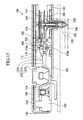
- The movement (machinery) of the analog timepiece used in the second example shall be explained first referring to FIGS. 14 to 17.
- A movement (machinery) 100 of an analog timepiece is provided with a support member of the movement 100 constituted from a main plate 102, a train wheel bridge 112, and a second wheel bridge 114; a winding stem 110 that is incorporated so as to be pivotable in a winding stem guide hole of the main plate 102; an insulating plate 160; a switch spring 162; a circuit block 116 that is fixed to the main plate 102 and the train wheel bridge 112 by the switch spring 162 through the insulating plate 160; a battery 120 that constitutes the power source of the analog timepiece; an IC 118 and a crystal oscillator 122 that are attached to the circuit block 116; a changeover spring 166 for determining the position of the axial direction of the winding stem 110 that is integrally formed with the switch spring 162; an hour motor 210 constituted from a coil block A212, a stator A214, and an hour rotor 216; an hour display wheel train constituted from an intermediate minute wheel 222, a minute wheel 224, and an hour wheel 226; a minute motor 240 constituted from a coil block B242, a stator B244, and a minute rotor 246; a minute display wheel train constituted from a second intermediate wheel B252, a second intermediate wheel A254, and a minute wheel 256; a second motor 270 constituted from a coil block C272, a stator C274, and a second rotor 276; and a second display wheel train constituted from a fifth wheel 282 and a second wheel 284.
- The movement (machinery) 100 is constituted so as to show the "hour" of the present time with an
hour hand 230 by rotation of the hour display wheel train from rotation of thehour motor 210. It is also constituted so as to show the "minute" of the present time with aminute hand 260 by rotation of the minute display wheel train from rotation of theminute motor 240. It is also constituted so as to show the "second" of the present time with asecond hand 290 by rotation of the second display wheel train from rotation of thesecond motor 270. - A rechargeable secondary battery can be used as the
battery 120, and a rechargeable capacitor can also be used. Thecrystal oscillator 122 constitutes the source oscillation of the analog timepiece, and oscillates at, for example, 32, 768 Hertz. - In the movement (machinery) 100, the sliding material of the first example was provided as follows in the bearing portion of the second motor 270 (the upper bearing portion constituted from the second
motor bearing portion 276a and thetrain wheel bridge 112, and the lower bearing portion constituted from the secondmotor bearing portion 276b and the main plate 102). - First, a portion of the sliding material obtained in the first example was separated to obtain a sliding material with a thickness of 1 µm.
- An epoxy-based adhesive was applied at a thickness of 0.1 µm on the second
motor bearing portion 276a and a portion of thetrain wheel bridge 112 in contact with the secondmotor bearing portion 276a. Simultaneously, an epoxy-based adhesive was applied to the secondmotor bearing portion 276b and a portion of themain plate 102 in contact with the secondmotor bearing portion 276b. - Then, the separated sliding material was attached to the applied epoxy-based adhesive, and the epoxy-based adhesive was sufficiently dried by being left to stand for one hour at 25°C.
- Similarly, the sliding material of the first example was also provided in the bearing portions of the
hour motor 210, the hour display wheel train, theminute motor 240, the minute display wheel train, and the second display wheel train. As a result, since friction loss of the sliding portion could be reduced, the battery life could be extended. - In the movement (machinery) 100, the sliding material of the first example was provided as follows in the bearing portion of the second motor 270 (the upper bearing portion constituted from the second
motor bearing portion 276a and thetrain wheel bridge 112, and the lower bearing portion constituted from the secondmotor bearing portion 276b and the main plate 102). - First, the sliding material obtained in the first example was ground to a particle diameter of 0.1 to 1 µm. Then a lubricant for clocks (SYNTHETIC OIL 9010 (made by MOEBIUS)) and the ground-up sliding material were mixed at a ratio of 10 parts sliding material to 100 parts lubricant.
- The lubricant mixed with the sliding material was applied on the second
motor bearing portion 276a and a portion of thetrain wheel bridge 112 in contact with the secondmotor bearing portion 276a. Simultaneously, the lubricant mixed with the sliding material was applied to the secondmotor bearing portion 276b and a portion of themain plate 102 in contact with the secondmotor bearing portion 276b. - Similarly, the sliding material of the first example was also provided in the bearing portions of the
hour motor 210, the hour display wheel train, theminute motor 240, the minute display wheel train, and the second display wheel train. As a result, since friction loss of the sliding portion could be reduced, the battery life could be extended. - Explained below is an example that provides the sliding material of the first example in the sliding portions of a mechanical timepiece in which a main spring serves as the power source.
- First, the movement (machinery) of the mechanical timepiece used in the fourth example shall be explained first referring to FIGS. 18 to 21.
- The movement (machinery) 300 of the mechanical timepiece has a
main plate 302 that constitutes a base plate of the movement. A windingstem 310 is incorporated so as to be pivotable in a windingstem guide hole 302a of themain plate 302. Normally, among the two sides of the main plate, the dial plate-side thereof is referred to as the "back side" of the movement, and the side opposite the dial plate side is referred to as the "front side" of the movement. The wheel train incorporated in the "front side" of the movement is referred to as the "outside wheel train", and wheel train incorporated in the "back side" of the movement is referred to as the "backside wheel train". The position in the axial direction of the windingstem 310 is determined by a changeover device that includes a settinglever 390, ayoke 392, alatch spring 394, and ayoke friction spring 396. A windingpinion 312 is rotatably provided in a guide shaft portion of the windingstem 310. - A
clutch wheel 398 is disposed so as to be coaxial with the windingstem 310 with respect to the angle portion of the windingstem 310. When the windingstem 310 is rotated to the state of being in a first winding stem position (zeroth step) that is nearest to the inside of the movement along the axis of rotation, the windingpinion 312 is constituted to turn via rotation of theclutch wheel 398. Acrown wheel 314 is constituted so as to rotate by rotation of the windingpinion 312. Aratchet wheel 316 rotates by rotation of thecrown wheel 314. Rotation of theratchet wheel 316 winds up themain spring 322 housed in abarrel wheel 320. Acenter wheel 324 is constituted so as to rotate by rotation of thebarrel wheel 320. Anescapement wheel 330 rotates through rotation of afourth wheel 328, athird wheel 326, and thecenter wheel 324. Thebarrel wheel 320, thecenter wheel 324, thethird wheel 326, and thefourth wheel 328 constitute the outside wheel train. - A
setting wheel 397 is rotatably disposed with respect to themain plate 302. Aminute wheel 358 is rotatably disposed with respect to themain plate 302. The gear portion of thesetting wheel 397 is constituted to mesh with the gear portion of the minute gearing of theminute wheel 358. The gear portion of the minute gearing of theminute wheel 358 is constituted so as to mesh with the gear portion of acannon pinion 350. The pinion portion of the minute pinion of theminute wheel 358 is constituted to mesh with the gear portion of acylinder wheel 354. Aminute pusher 384 supports thesetting wheel 397 and theminute wheel 358 so as to be rotatable with respect to themain plate 302. When the windingstem 310 is rotated to the state of being in a second winding stem position (first step) on the outside of the movement along the axis of rotation, thesetting wheel 397 is constituted to rotate by rotation of theclutch wheel 398. Moreover, when the windingstem 310 is rotated to the state of being in the first step, theminute wheel 358 is constituted to rotate by rotation of thesetting wheel 397. In this state, when theminute wheel 358 rotates, thecannon pinion 350 and thecylinder wheel 354 rotate, and accordingly anhour hand 356 and aminute hand 352 rotate, so that time correction of the timepiece can be performed. - An escapement/controller that controls the rotation of the outside wheel train includes a
balance 340, anescapement wheel 330, and anpallet fork 342. Thebalance 340 includes abalance staff 340a, a balance wheel andbalance spring 340c. Based on rotation of thecenter wheel 324, thecannon pinion 350 rotates simultaneously. Theminute hand 352 attached to thecannon pinion 350 shows "minutes". A slip mechanism with respect to thecenter wheel 324 is provided in thecannon pinion 350. Based on rotation of thecannon pinion 350, thecylinder wheel 354 rotates via rotation of theminute wheel 358. Thehour hand 356 attached to thecylinder wheel 354 shows the "hour". Thebalance spring 340c is a flat spring with a swirling (spiral) shape having a plurality of windings. The inner end portion of thebalance spring 340c is fixed to acollet 340d that is fixed to thebalance staff 340a, and the outer end portion of thebalance spring 340c is fixed by a screw fastening through astud 370a that is attached to astud support 370 that is fixed to abalance bridge 366. Aregulator pin 368 is rotatably attached to thebalance bridge 366. Thebalance 340 is supported so as to be rotatable with respect to themain plate 302 and thebalance bridge 366. - The
barrel wheel 320 is provided with abarrel drum 320d, abarrel arbor 320f, and amain spring 322. Thebarrel arbor 320f includes anupper shaft 320a and alower shaft 320b. Thebarrel arbor 320f is formed with a metal such as carbon steel. Thebarrel drum 320d is formed with a metal such as brass. Thecenter wheel 324 includes anupper shaft 324a, alower shaft 324b, apinion portion 324c, agearwheel portion 324d, and abead portion 324h. Thepinion portion 324c of thecenter wheel 324 is constituted so as to mesh with thebarrel drum 320d. Theupper shaft 324a, thelower shaft 324b, and thebead portion 324b are formed with a metal such as carbon steel. Thegearwheel portion 324d is formed with a metal such as brass. Thethird wheel 326 includes anupper shaft 326a, alower shaft 326b, apinion portion 326c, and agearwheel portion 326d. Thepinion portion 326c of thethird wheel 326 is constituted so as to mesh with thegearwheel portion 324d. Thefourth wheel 328 includes anupper shaft 328a, alower shaft 328b, apinion portion 328c, and agearwheel portion 328d. Theupper shaft 328a and thelower shaft 328b are formed with a metal such as carbon steel. Thegearwheel portion 328d is formed with a metal such as brass. Theescapement wheel 330 includes anupper shaft 330a, alower shaft 330b, apinion portion 330c, and agearwheel portion 330d. Thepinion portion 330c of theescapement wheel 330 is constituted so as to mesh with thegearwheel portion 328d. Thegearwheel portion 328d of theescapement wheel 330 is constituted so as to mesh with apallet stone 343 that is bonded to thepallet fork 342. Thepallet fork 342 is provided with an pallet fork (incomplete) 342d and anpallet staff 342f. Thepallet staff 342f includes anupper shaft 342a and alower shaft 342b. - The
barrel wheel 320 is supported so as to be rotatable with respect to themain plate 302 and abarrel bridge 360. That is, theupper shaft 320a of thebarrel arbor 320f is supported so as to be rotatable with respect to thebarrel bridge 360. Thelower shaft 320b of thebarrel arbor 320f is supported so as to be rotatable with respect to themain plate 302. Thecenter wheel 324, thethird wheel 326, thefourth wheel 328, and theescapement wheel 330 are supported so as to be rotatable with respect to themain plate 302 and atrain wheel bridge 362. That is, theupper shaft 324a of thecenter wheel 324, theupper shaft 326a of thethird wheel 326, theupper shaft 328a of thefourth wheel 328, and theupper shaft 330a of theescapement wheel 330 are supported so as to be rotatable with respect to thetrain wheel bridge 362. Also, thelower shaft 324b of thecenter wheel 324, thelower shaft 326b of thethird wheel 326, thelower shaft 328b of thefourth wheel 328, and thelower shaft 330b of theescapement wheel 330 are supported so as to be rotatable with respect to themain plate 302. Thepallet fork 342 is supported so as to be rotatable with respect to themain plate 302 and an pallet fork bearing 364. That is, theupper shaft 342a of thepallet fork 342 is supported so as to be rotatable with respect to the pallet fork bearing 364. Thelower shaft 342b of thepallet fork 342 is rotatably supported with respect to themain plate 302. - In the movement (machinery) 300, the sliding material of the first example was provided as follows in the sliding portion with the escapement wheel 330 (the
gearwheel portion 330d) and thepallet stone 343. - First, a portion of the sliding material obtained in the first example was separated to obtain a sliding material with a thickness of 1 µm.
- An epoxy-based adhesive was applied at a thickness of 0.1 µm on the
gearwheel portion 330d of theescape wheel 330 and thepallet stone 343. - Then, the separated sliding material was attached to the applied epoxy-based adhesive, and the epoxy-based adhesive was sufficiently dried by being left to stand for one hour at 25°C.
- Similarly, the sliding material of the first example was also provided in the bearing portions of the
center wheel 324, thethird wheel 326, thefourth wheel 328, thebalance staff 340a and the changeover wheel. As a result, since friction loss of the sliding portion could be reduced, the duration of the main spring could be extended. - In the movement (machinery) 300, the sliding material of the first example was provided as follows in the sliding portion with escape wheel 330 (the
gearwheel portion 330d) and thepallet stone 343. - First, the sliding material obtained in the first example was ground to a particle diameter of 0.1 to 1 µm. Then a lubricant for timepieces (SYNTHETIC OIL 9010 (made by MOEBIUS)) and the ground-up sliding material were mixed at a ratio of 10 parts sliding material to 100 parts lubricant.
- The lubricant mixed with the sliding material was applied on the
gearwheel portion 330d of theescapement wheel 330 and thepallet stone 343. - Similarly, the sliding material of the first example was also provided in the bearing portions of the
center wheel 324, thethird wheel 326, thefourth wheel 328, thebalance staff 340a and the changeover wheel. As a result, since friction loss of the sliding portion could be reduced, the duration of the main spring could be extended. - The sliding material of the present invention can be used in machines/devices of various sizes ranging from heavy machinery such as automobiles to nanomachines without restrictions on the environment it can be used, can minimize friction compared to conventional types, and has superior durability.
-
- Fig. 1 is a structural model showing an example of a sliding material of the present invention.
- Fig. 2 is a drawing showing one manufacturing step of the sliding material of the example.
- Fig. 3 is a drawing showing one manufacturing step of the sliding material of the example.
- Fig. 4 is a drawing showing one manufacturing step of the sliding material of the example.
- Fig. 5 is a photograph and a schematic view of the sliding material obtained in the example.
- Fig. 6 is a high-resolution electron microscope image of the sliding material obtained in the example.
- Fig. 7 is a diffraction pattern of the sliding material obtained in the example.
- Fig. 8 is a graph showing the frictional characteristics (
load 0 nN) of the sliding material obtained in the example. - Fig. 9 is a graph showing the frictional characteristics (load 10 nN) of the sliding material obtained in the example.
- Fig. 10 is a graph showing the frictional characteristics (load 20 nN) of the sliding material obtained in the example.
- Fig. 11 is a graph showing the frictional characteristics (load 60 nN) of the sliding material obtained in the example.
- Fig. 12 is a graph showing the frictional characteristics (load 100 nN) of the sliding material obtained in the example.
- Fig. 13 is a graph showing the frictional characteristics (load 10 µN) of the sliding material obtained in the example.
- Fig. 14 is a plan view showing the outline shape of the movement in the example of an analog timepiece of the present invention, seen from the front.
- Fig. 15 is an outline partial sectional view showing the portion of the second hand from the second motor in the example of an analog timepiece of the present invention.
- Fig. 16 is an outline partial sectional view showing the portion of the minute hand from the minute motor in the example of an analog timepiece of the present invention.
- Fig. 17 is an outline partial sectional view showing the portion of the second hand from the second motor in the example of an analog timepiece of the present invention.
- Fig. 18 is a plan view showing the outline shape of the front of the movement in the example of the mechanical timepiece of the present invention.
- Fig. 19 is an outline partial sectional view of the example of the mechanical timepiece of the present invention, showing a portion of the pallet fork from the barrel.
- Fig. 20 is an outline partial sectional view of the example of the mechanical timepiece of the present invention, showing a portion of the balance from the escapement wheel.
- Fig. 21 is an outline partial sectional view of the example of the mechanical timepiece of the present invention, showing a portion of the winding stem, the setting wheel, and the minute wheel.
-
- 1
- sliding material
- 2
- graphite
- 3
- graphite layer
- 4
- C60 molecule
- 11
- stirrer
- 12
- HOPG
- 13
- furnace
- 14
- quartz tube
- 100
- movement (machinery)
- 102
- main plate
- 110
- winding stem
- 112
- train wheel bridge
- 114
- second bridge
- 116
- circuit block
- 118
- IC
- 120
- battery
- 122
- crystal oscillator
- 160
- insulating plate
- 162
- switch spring
- 166
- changeover spring
- 210
- hour motor
- 212
- coil block
- 214
- stator
- 216
- hour rotor
- 222
- intermediate minute wheel
- 224
- minute wheel
- 226
- hour wheel
- 230
- hour hand
- 240
- minute motor
- 242
- coil block B
- 244
- stator B
- 246
- minute rotor
- 252
- second intermediate wheel B
- 254
- second intermediate wheel A
- 256
- minute wheel
- 260
- minute hand
- 270
- second motor
- 272
- coil block C
- 274
- stator C
- 276
- second rotor
- 276a
- second motor bearing portion
- 276b
- second motor bearing portion
- 282
- fifth wheel
- 284
- second wheel
- 300
- movement (machinery)
- 302
- main plate
- 302a
- winding stem guide hole
- 310
- winding stem
- 312
- winding pinion
- 314
- crown wheel
- 316
- ratchet wheel
- 320
- barrel wheel
- 320a
- uppershaft
- 320b
- lower shaft
- 320d
- barrel drum
- 320f
- barrel arbor
- 322
- main spring
- 324
- center wheel
- 324a
- upper shaft
- 324b
- lower shaft
- 324c
- pinion portion
- 324d
- gearwheel portion
- 324h
- bead portion
- 326
- third wheel
- 326a
- upper shaft
- 326b
- lower shaft
- 326c
- pinion portion
- 326d
- gearwheel portion
- 328
- fourth wheel
- 328a
- upper shaft
- 328b
- lower shaft
- 328c
- pinion portion
- 328d
- gearwheel portion
- 330
- escapement wheel
- 330d
- gearwheel portion
- 340
- balance
- 340a
- balance staff
- 340c
- balance spring
- 340d
- collet
- 342
- pallet fork
- 342a
- upper shaft
- 342b
- lower shaft
- 342d
- pallet fork (incomplete)
- 342f
- pallet staff
- 350
- cannon pinion
- 352
- minute hand
- 354
- cylinder wheel
- 356
- hour hand
- 358
- minute wheel
- 360
- barrel bridge
- 362
- train wheel bridge
- 364
- pallet fork bearing
- 366
- balance bridge
- 368
- regulator pin
- 370
- stud support
- 370a
- stud
- 384
- minute pusher
- 390
- setting lever
- 392
- latch
- 394
- latch spring
- 396
- yoke friction spring
- 397
- setting wheel
- 398
- clutch wheel
Claims (13)
- A sliding material having
hexagonal crystals that form a layer structure, and
ball-shaped molecules inserted in interlayers of the hexagonal crystals. - A sliding material according to claim 1, wherein the structure in which the ball-shaped molecules are inserted in interlayers of the hexagonal crystals exists in plurality repetition in the thickness direction.
- A sliding material according to claim 1, wherein the ball-shaped molecules form a monolayer in each interlayer of the hexagonal crystals.
- A sliding material according to claim 2, wherein the distance between the ball-shaped molecules in the thickness direction is 1.4 nanometers or less.
- A sliding material according to claim 3, wherein the distance between the ball-shaped molecules in the thickness direction is 1.4 nanometers or less.
- A sliding material according to claim 1, wherein the ball-shaped molecules have five-member rings or six-member rings of carbon.
- A sliding material that is a mixture of the sliding material recited in claim 1 and a solid or fluid.
- A sliding material wherein the sliding material recited in claim 1 is provided on a solid surface.
- A method of manufacturing a sliding material comprising:widening the interlayer of hexagonal crystals forming a layer structure; andinserting ball-shaped molecules in the interlayer of the hexagonal crystals.
- A method of manufacturing a sliding material recited in claim 9, wherein the ball-shaped molecules are inserted in the interlayer of the hexagonal crystals by sublimating the ball-shaped molecules.
- A device having a sliding portion in which at least one member slides with respect to another member, and
being provided with the sliding material recited in any one of claims 1 through 8 on the surface of at least one member of the sliding portion. - A timepiece having at least one gear set that transmits power and a changeover mechanism that corrects the time,
wherein the gear set and/or the changeover mechanism have/has a sliding portion in which at least one member slides with respect to another member, and
the sliding material recited in any one of claims 1 through 8 is provided on the surface of at least one member of the sliding portion. - A motor having a sliding portion in which at least one member slides with respect to another member, and
being provided with the sliding material recited in any one of claims 1 through 8 on the surface of at least one member of the sliding portion.
Applications Claiming Priority (1)
| Application Number | Priority Date | Filing Date | Title |
|---|---|---|---|
| PCT/JP2004/018016 WO2006059391A1 (en) | 2004-12-03 | 2004-12-03 | Slide material, process for producing the same and apparatus utilizing the slide material |
Publications (3)
| Publication Number | Publication Date |
|---|---|
| EP1829953A1 true EP1829953A1 (en) | 2007-09-05 |
| EP1829953A4 EP1829953A4 (en) | 2007-12-26 |
| EP1829953B1 EP1829953B1 (en) | 2009-11-11 |
Family
ID=36564835
Family Applications (1)
| Application Number | Title | Priority Date | Filing Date |
|---|---|---|---|
| EP04822487A Active EP1829953B1 (en) | 2004-12-03 | 2004-12-03 | Slide material, process for producing the same and apparatus utilizing the slide material |
Country Status (6)
| Country | Link |
|---|---|
| US (1) | US20070178043A1 (en) |
| EP (1) | EP1829953B1 (en) |
| JP (1) | JP4785741B2 (en) |
| CN (1) | CN100540641C (en) |
| DE (1) | DE602004024136D1 (en) |
| WO (1) | WO2006059391A1 (en) |
Families Citing this family (5)
| Publication number | Priority date | Publication date | Assignee | Title |
|---|---|---|---|---|
| US20080130424A1 (en) * | 2006-12-04 | 2008-06-05 | Seiko Epson Corporation | Timepiece component and timepiece having the timepiece component |
| JP2010053000A (en) * | 2008-08-29 | 2010-03-11 | Koji Miura | Intercalation compound material and method for producing the same |
| JP2011102780A (en) * | 2009-11-11 | 2011-05-26 | Seiko Instruments Inc | Component for timepiece and timepiece |
| JP5591755B2 (en) * | 2011-04-22 | 2014-09-17 | 大豊工業株式会社 | Sliding agent, resin sliding material, sliding member, and manufacturing method of sliding agent |
| CN115004552A (en) | 2020-06-28 | 2022-09-02 | 深圳清华大学研究院 | In-plane sliding type parallel capacitor radio frequency switch based on suspension potential |
Citations (1)
| Publication number | Priority date | Publication date | Assignee | Title |
|---|---|---|---|---|
| US20040033189A1 (en) * | 2002-08-15 | 2004-02-19 | Graftech Inc. | Graphite intercalation and exfoliation process |
Family Cites Families (10)
| Publication number | Priority date | Publication date | Assignee | Title |
|---|---|---|---|---|
| US5558903A (en) * | 1993-06-10 | 1996-09-24 | The Ohio State University | Method for coating fullerene materials for tribology |
| US5403665A (en) * | 1993-06-18 | 1995-04-04 | Regents Of The University Of California | Method of applying a monolayer lubricant to micromachines |
| US6001784A (en) * | 1993-10-05 | 1999-12-14 | Nalco Chemical Company | High melt point solid film prelube emulsion for use on aluminum and other metals |
| DE4430130A1 (en) * | 1994-08-25 | 1996-02-29 | Fischer Artur Werke Gmbh | Process for the production of interlocking metal parts |
| JPH0925490A (en) * | 1995-07-10 | 1997-01-28 | Osaka Prefecture | Solid lubricant for ultrahigh-vacuum |
| JP4353550B2 (en) * | 1998-04-15 | 2009-10-28 | 三菱鉛筆株式会社 | Carbon-based composite sliding material having self-lubricating property and manufacturing method thereof |
| GB2380496B (en) | 2000-06-01 | 2004-05-12 | Seagate Technology Llc | Process for production of ultrathin protective overcoats |
| JP2002105623A (en) * | 2000-09-27 | 2002-04-10 | Kobe Steel Ltd | Carbon onion thin film and manufacturing method |
| JP3704071B2 (en) | 2001-08-27 | 2005-10-05 | 独立行政法人科学技術振興機構 | Lubrication system with carbon ball molecules or carbon tube molecules |
| JP2003313571A (en) * | 2002-04-19 | 2003-11-06 | Japan Science & Technology Corp | Carbon nanohorn solid lubricant |
-
2004
- 2004-12-03 EP EP04822487A patent/EP1829953B1/en active Active
- 2004-12-03 US US11/570,164 patent/US20070178043A1/en not_active Abandoned
- 2004-12-03 DE DE602004024136T patent/DE602004024136D1/en active Active
- 2004-12-03 CN CNB2004800429914A patent/CN100540641C/en active Active
- 2004-12-03 JP JP2006520541A patent/JP4785741B2/en active Active
- 2004-12-03 WO PCT/JP2004/018016 patent/WO2006059391A1/en active Application Filing
Patent Citations (1)
| Publication number | Priority date | Publication date | Assignee | Title |
|---|---|---|---|---|
| US20040033189A1 (en) * | 2002-08-15 | 2004-02-19 | Graftech Inc. | Graphite intercalation and exfoliation process |
Non-Patent Citations (3)
| Title |
|---|
| "Kirk Othmer Encyclopedia of Chemical Technology Vol.4" 1978, JOHN WILEY & SONS , NEW YORK , XP002458699 * page 556 * * page 691 * * page 703 - page 704 * * |
| FUHRER, HOU, XIANG, ZETTL: "C60 Intercalated Graphite Predictions and Experiments" SOLID STATE COMMUNICATIONS, vol. 90, no. 6, May 1994 (1994-05), pages 357-360, XP002458698 * |
| See also references of WO2006059391A1 * |
Also Published As
| Publication number | Publication date |
|---|---|
| US20070178043A1 (en) | 2007-08-02 |
| CN100540641C (en) | 2009-09-16 |
| WO2006059391A1 (en) | 2006-06-08 |
| DE602004024136D1 (en) | 2009-12-24 |
| EP1829953A4 (en) | 2007-12-26 |
| JP4785741B2 (en) | 2011-10-05 |
| EP1829953B1 (en) | 2009-11-11 |
| CN1954058A (en) | 2007-04-25 |
| JPWO2006059391A1 (en) | 2008-06-05 |
Similar Documents
| Publication | Publication Date | Title |
|---|---|---|
| EP2239637B1 (en) | Timepiece wheel train and timepiece | |
| EP1225353A1 (en) | Rolling apparatus | |
| EP1829953B1 (en) | Slide material, process for producing the same and apparatus utilizing the slide material | |
| US7170827B2 (en) | Timepiece, having bearing portion formed of resin and wheel train | |
| RU2605828C1 (en) | Clock mechanism having contact pair without lubrication | |
| CN102033484A (en) | Timepiece bearing, movement, and portable timepiece | |
| BR112013013370B1 (en) | sliding element, in particular, piston ring with a coating | |
| RU2716851C1 (en) | Pinion, clock mechanism, clock or measuring device without magnetic signature | |
| Zhu et al. | Effect of the anion on the tribological properties of ionic liquid nano-films on surface-modified silicon wafers | |
| Xu et al. | Growth and characteristics of self-assembled MoS2/Mo-SC nanoperiod multilayers for enhanced tribological performance | |
| Shtansky et al. | Structure and properties of multi-component and multilayer TiCrBN/WSex coatings deposited by sputtering of TiCrB and WSe2 targets | |
| RU2718342C1 (en) | Clock component with improved self-lubricant | |
| Lungu | Nanostructure influence on DLC-Ag tribological coatings | |
| CN101192045A (en) | Timepiece component and timepiece having the timepiece component | |
| CN101196725A (en) | Timepiece component and timepiece having the timepiece component | |
| RU2341556C2 (en) | Sliding material, method of its production and device, in which sliding material is used | |
| RU2752467C2 (en) | Clockwork mechanism component | |
| Lobova et al. | Effect of Substrate Condition on the Structural and Tribotechnical Characteristics of Molybdenum Diselenide (MoSe 2) Coatings | |
| WO2004020854A1 (en) | Ball bearing and self-winding watch | |
| JP2009210552A (en) | Contact component and timepiece | |
| US20080130424A1 (en) | Timepiece component and timepiece having the timepiece component | |
| Fu et al. | Dry-sliding tribological properties of nano-eutectic Fe 83 B 17 alloy | |
| Kılınç et al. | Dry Sliding Wear Behavior of Cr-Al-N Diffusion Coatings against Silicon Nitride | |
| JP2013238627A (en) | Timepiece wheel train and timepiece | |
| JP2002257951A (en) | Clock component |
Legal Events
| Date | Code | Title | Description |
|---|---|---|---|
| PUAI | Public reference made under article 153(3) epc to a published international application that has entered the european phase |
Free format text: ORIGINAL CODE: 0009012 |
|
| 17P | Request for examination filed |
Effective date: 20061115 |
|
| AK | Designated contracting states |
Kind code of ref document: A1 Designated state(s): CH DE LI |
|
| A4 | Supplementary search report drawn up and despatched |
Effective date: 20071128 |
|
| 17Q | First examination report despatched |
Effective date: 20080207 |
|
| DAX | Request for extension of the european patent (deleted) | ||
| RBV | Designated contracting states (corrected) |
Designated state(s): CH DE LI |
|
| GRAP | Despatch of communication of intention to grant a patent |
Free format text: ORIGINAL CODE: EPIDOSNIGR1 |
|
| GRAS | Grant fee paid |
Free format text: ORIGINAL CODE: EPIDOSNIGR3 |
|
| GRAA | (expected) grant |
Free format text: ORIGINAL CODE: 0009210 |
|
| AK | Designated contracting states |
Kind code of ref document: B1 Designated state(s): CH DE LI |
|
| REG | Reference to a national code |
Ref country code: CH Ref legal event code: NV Representative=s name: RITSCHER & PARTNER AG Ref country code: CH Ref legal event code: EP |
|
| REF | Corresponds to: |
Ref document number: 602004024136 Country of ref document: DE Date of ref document: 20091224 Kind code of ref document: P |
|
| PLBE | No opposition filed within time limit |
Free format text: ORIGINAL CODE: 0009261 |
|
| STAA | Information on the status of an ep patent application or granted ep patent |
Free format text: STATUS: NO OPPOSITION FILED WITHIN TIME LIMIT |
|
| 26N | No opposition filed |
Effective date: 20100812 |
|
| REG | Reference to a national code |
Ref country code: CH Ref legal event code: PFA Owner name: AICHI UNIVERSITY OF EDUCATION, JP Free format text: FORMER OWNER: AICHI UNIVERSITY OF EDUCATION, JP |
|
| PGFP | Annual fee paid to national office [announced via postgrant information from national office to epo] |
Ref country code: CH Payment date: 20230101 Year of fee payment: 19 |
|
| PGFP | Annual fee paid to national office [announced via postgrant information from national office to epo] |
Ref country code: DE Payment date: 20231031 Year of fee payment: 20 |