EP1832309A2 - Implantable medical electrode device, in particular cardiovascular pacemaker or defibrillator electrode device - Google Patents
Implantable medical electrode device, in particular cardiovascular pacemaker or defibrillator electrode device Download PDFInfo
- Publication number
- EP1832309A2 EP1832309A2 EP07003085A EP07003085A EP1832309A2 EP 1832309 A2 EP1832309 A2 EP 1832309A2 EP 07003085 A EP07003085 A EP 07003085A EP 07003085 A EP07003085 A EP 07003085A EP 1832309 A2 EP1832309 A2 EP 1832309A2
- Authority
- EP
- European Patent Office
- Prior art keywords
- electrode device
- fixing zone
- electrode
- electrode body
- wall
- Prior art date
- Legal status (The legal status is an assumption and is not a legal conclusion. Google has not performed a legal analysis and makes no representation as to the accuracy of the status listed.)
- Granted
Links
Images


Classifications
-
- A—HUMAN NECESSITIES
- A61—MEDICAL OR VETERINARY SCIENCE; HYGIENE
- A61N—ELECTROTHERAPY; MAGNETOTHERAPY; RADIATION THERAPY; ULTRASOUND THERAPY
- A61N1/00—Electrotherapy; Circuits therefor
- A61N1/02—Details
- A61N1/04—Electrodes
- A61N1/05—Electrodes for implantation or insertion into the body, e.g. heart electrode
- A61N1/056—Transvascular endocardial electrode systems
- A61N1/057—Anchoring means; Means for fixing the head inside the heart
- A61N2001/0578—Anchoring means; Means for fixing the head inside the heart having means for removal or extraction
-
- A—HUMAN NECESSITIES
- A61—MEDICAL OR VETERINARY SCIENCE; HYGIENE
- A61N—ELECTROTHERAPY; MAGNETOTHERAPY; RADIATION THERAPY; ULTRASOUND THERAPY
- A61N1/00—Electrotherapy; Circuits therefor
- A61N1/02—Details
- A61N1/04—Electrodes
- A61N1/05—Electrodes for implantation or insertion into the body, e.g. heart electrode
- A61N1/056—Transvascular endocardial electrode systems
- A61N2001/0585—Coronary sinus electrodes
Definitions
- the invention relates to an implantable medical electrode device, and more particularly to a cardiovascular pacemaker or defibrillator electrode device.
- implantable electrode devices must be anchored to a particular body site so that they do not change their position over time. This is particularly important when such electrode devices in a moving organ, such. B. in the heart, are implanted.
- fixation devices such as screws, needles, hooks, anchors (so-called tines) or protrusions and corresponding undercuts, on whose elongated tubular electrode body in a fixation zone in front of the distal end, into which the tissue can grow ,
- a special feature is the fixation in a blood vessel, since in particular here sharp tips or edges of the fixation device can cause injuries or at least irritation to the vessel wall. For this reason, conventional fixators are designed so that they jam by their shape in the vessel.
- Electrodes which have for fixing the above-mentioned "tines", silicone screws or helical or hook-shaped electrode body.
- the electrode body can form fit to the angles and outlets of, for example, veins in the cardiovascular system and thus achieve a fixation. In straight veins can be done by the extension of these targeted kinks a positional fixation.
- electrodes are used which have distally a helix-shaped electrode body which is clamped to the vessel wall by expansion forces.
- a particularly simple fixation technique which does not achieve the optimal results therapeutically is a wedging of the distal tip of the electrode body in a vessel.
- the electrode body is advanced so far, for example, in the left ventricular venous branches until the tip of the electrode body is stuck in the vein and assumes a "wedge position". In this the vein is closed.
- the invention has for its object to provide an electrode device which allows on the one hand a reliable, but on the other hand also reversible fixation and is relatively atraumatic.
- the electrode body is provided in the region of its fixation with an outwardly closed peripheral sheath, which is reversibly expandable for releasable fixation in a body lumen.
- Expansion means provided, which can be formed most diverse. It should be noted with regard to the peripheral envelope closed to the outside that this may be the wall of the actual electrode body of the electrode device, but also a separate tube pulled over the electrode body.
- the fixation zone Because of the above construction of the fixation zone according to the invention, secure, atraumatic fixation of the electrode device in, for example, a venous vessel in the heart is possible by the peripheral sheath by the expansion means (such as fluid pressure, a balloon or axial pull / pressure on the fixation zone) at the desired position is expanded widely until the peripheral hull is defined in the vessel.
- the expansion means such as fluid pressure, a balloon or axial pull / pressure on the fixation zone
- a fixation is recognizable - within certain limits of course - regardless of the diameter of the body lumen. Since an outwardly closed shell expands in the fixation no sharp wires, corners or edges, so that the fixation - as provided under the task - is very atraumatic.
- an implantable medical electrode device in the form of a cardiac catheter indicated as a whole by 1, has an elongate, tube-like electrode body 2 which is located in front of the distal end 3 ( Figure 3) with a fixation zone 4 mm long is provided. Inside the electrode body 2 run in a separate inner tube 5, the coiled electrode leads 6, with which the pacing electrodes 7 shown for example in FIG. 3 are supplied with voltage.
- the wall 8 of the electrode body 2 is formed more flexibly than in the adjacent remaining areas.
- a stent-like, plastically deformable support structure 9 in the wall material embedded is a substantially tubular, plastically deformable, expandable expanded metal or plastic molded part.
- the expansion forces of this support structure 9 are by suitable choice of material and structuring of the webs 10 - vote by matching the web width, web height, the shape of the bending leg, etc. - on the elastic and geometric properties of the embedding material of the wall 8 of the fixing zone 4, which in turn the wall thickness and the choice of material, such as latex, silicone, polyurethane, is determined.
- a supply device 12 is provided around the electrode body 2, via the means of a syringe 13 via the connected feed line 14, a hydraulic pressure medium, such as physiological saline, in as pressure-tight Tube formed electrode body 2 with a pressure p H can be pressed.
- the proximal end 11 of the cardiac catheter 1 is formed by a connection plug 15 for the individual stimulation electrodes 7.
- the feeding device 12 is shown in FIG. 4.
- the connection 16 of the feed line 14 is located centrally in the wall of a cylindrical sleeve 17 surrounding the electrode body 2, between the end openings of which and the electrode body 2 each O-ring seals 18 are fitted. These are acted upon by sealing sleeves 47 which can be screwed onto the cylinder sleeve 17 so that the pressurized fluid can be pressed into the annular space between the electrode body 2 and the inner tube 5 via the connection 16 and a feed opening 19.
- the cardiac catheter 1 is advanced, for example, into the coronary sinus with its distal end 3 until the desired position of the stimulation electrodes 7 has been reached.
- the X-ray controllability of this process is by an appropriate design of the support structure 9 of a radiopaque material, such as suitable coated plastic, stainless steel, platinum, titanium alloys, magnesium or gold can be improved.
- the support structure 9 is widened plastically there and thus expands radially, as can be seen in Fig. 2. This is continued until the fixation zone 4 with its enlarged diameter rests against the vessel inner wall (not shown here) and thus fixes the cardiac catheter 1 in this position.
- the pressurized fluid is sucked off, whereby a negative pressure is created, which ensures that the fixing zone 4 contracts again, while the support structure 9 quasi collapses, which again the configuration shown in Fig. 1 is achieved and the Cardiac catheter 1 is freely movable.
- the expansion diameter D in the fixing zone 4 can be directly influenced by controlling the introduced volume of the pressure fluid or by the applied pressure, even in the case of a pneumatic control.
- the pressurized fluid can also be transmitted through an eccentric additional lumen in the electrode body 2 or through an outer, coaxially arranged tube, as is not shown in detail in the figures.
- an axial deformability can also be achieved by suitable shaping of the embedded support structure 9, so that the cardiac catheter 1 remains sufficiently flexible for placement in the vessels even in the region of the fixation zone 4.
- an additional definition of the cardiac catheter 1 can be achieved by suitable structuring of the outer surface of the fixation zone 4.
- web-shaped anchoring elements 20 are provided on the outside, distributed over the circumference, parallel to the longitudinal direction of the electrode body 2. In the unexpanded configuration, these anchoring elements are located 20 flat on the outside of the cardiac catheter 1, so that a smooth introduction is guaranteed.
- the anchoring elements 20 may be designed soft or stiff depending on the choice of material. Suitable materials are elastomers, other plastics or metals.
- the fixing zone 4 is provided with a designated as a whole with 21 drape configuration, which acts together with a coaxial with the electrode body applied tensile or shear loading as expansion means and will be explained in more detail below with reference to the individual figures.
- FIG. 6 shows a reduction in the wall thickness of the electrode body 2 in the region of the fixation zone 4.
- FIG. 8 an embodiment is shown in which three annular folds 22 lined up in the axial direction arise by three juxtaposed in the axial direction, narrow WandungsverPhynonne when pulling the Switzerlanddrahtung.
- the annular folds 22 also form a sawtooth profile after the expansion, as shown in Fig. 9.
- the holding force in the extension direction of the cardiac catheter 1 is greater than in the insertion direction.
- the wall 8 is designed so that when expanding with the help of (not shown) puller wire, the annular folds 22 slide over each other, so that several centrally located inner folds 23 and a plurality of peripherally located outer folds 24 arise.
- the increase in diameter of the electrode body 2 is based not only on a pure wrinkling, but also on a thickening of the material by forming a plurality, preferably at least three layers.
- Fig. 11 and 12 shows an embodiment in which a single annular fold 22 is formed, which pushes through introduced into the wall 8 thickenings 25 in layers over each other, that a locking of the layers takes place. If the inner fold 23 is pushed under the outer fold 24 when the fold is pushed together, the thickening 25 of the inner fold 23 snaps behind the corresponding thickening 25 of the outer fold 24, whereby the configuration formed is determined.
- FIG. 14 shows the corresponding region of the cardiac catheter 1 in the stretched state, in which the anchoring elements 20 conform to the elongate electrode body 2.
- the electrode body 2 in the fixing zone 4 is designed with regard to its choice of material and the wall diameter such that the flanks 26 of the forming annular folds 22 are stiffened. If the cardiac catheter 1, as shown in this figure, positioned in the vessel 27, the pull wire, not shown, is actuated and wrinkling occurs, as shown in Fig. 16 in an intermediate state. In this Condition, the vessel 27 is slightly overstretched. Upon further actuation of the puller wire, the annular folds 22 again fold over the radially maximally extended configuration, so that the stiffened flanks 26 lie one above the other and fix the cardiac catheter 1 in the vessel 27 (FIG. 17).
- a spreading device 28 is provided in the electrode body 2 in the region of the fixing zone 4, which supports the formation of wrinkles.
- This spreading device 28 has a cone 29 fixed in the electrode body 2, which cooperates with a spreading sleeve 31 mounted distally in front of it and acted upon by the puller wire 30.
- the cone 29 engages under the spreading arms 32 of the expansion sleeve 31, which thus radially expand and thus contribute to the formation of the annular fold 22.
- the wrinkling and the unfolding of the anchoring elements 20 is reversible.
- the wrinkling can be optimized both by varying the wall thicknesses of the electrode body 2 in the fixing zone 4 and by varying the degrees of hardness of the material or by preforming with memory effect.
- the distal end of the fixing zone 4 may be connected to a pull wire or pull cable which runs inside the electrode body 2 and is arranged to be movable relative thereto.
- the proximal end of the puller wire extends beyond the proximal end of the electrode body 2. Pulling on the puller wire or retaining the puller wire while simultaneously pushing the electrode body 2 forwardly allows the distal and proximal ends of the fixation zone 4 to move toward one another, which causes bulging of the annular fold 22, possibly forming the inner and outer fins Outside folds 23, 24 generated.
- a release of the resulting fixation of the cardiac catheter 1 can be achieved by pushing on the pull wire, if this is sufficiently stiff.
- a stylet may be inserted into the electrode body 2 with which the distal end of the flexible area is pushed forward again.
- the puller wire with the distal end can also serve as an abutment when the proximal part of the electrode body 2 is retracted. In any case, this will result in a contracting and smoothing of the wrinkles and a stretching of the fixation zone 4 with the release of the cardiac catheter 1.
- FIGS. 20 to 24 show a further variant for the expansion and contraction of the cardiac catheter 1 in the region of its fixation zone 4.
- the basis of this is the bistable tilting element 33 shown in plan view in FIG. 20, which consists of two limbs 34, 35 each bent in an S-shape. These are placed mirror-inverted and riveted together at the intersection points 36.
- an anchoring element 37 in the form of a sheet metal lamination is again attached, which is inwardly in the direction of the main axis connecting the crossing points 36.
- the two legs 34, 35 form - as Fig. 20 shows well - in plan view the shape of an eighth
- FIG. 21 shows two such tilting elements 33 in a configuration that corresponds to the expanded state in the application shown in FIGS. 23 and 24.
- the anchoring elements 37 carrying portions of the legs 34, 35 are convex, the remaining portions bent concave. This is a stable end position, which is umschnappbar by applying the concave portions of the legs 34, 35 outwardly into the second stable end position shown in Fig. 22.
- the anchoring elements 37 carrying portions of the legs 34, 35 are bent concavely, while the remaining portions are now convex.
- the tilting element 33 is thus umschnappbar between a concave-convex and convex-concave configuration for transfer between the expanded and the contracted state.
- the tilting element 33 with its legs 34, 35 is completely embedded in the wall 8 of the electrode body 2, so that the latter in turn forms an envelope closed to the outside. Only the anchoring elements 37 protrude out of the wall 8 to the outside.
- the embedded tilting elements 33 are brought into that bistable end position in which the anchoring elements 37 are retracted by concave shaping of the corresponding sections of the legs 34, 35.
- a deflated catheter balloon 39 is drawn as an expansion agent through the electrode body 2 to below this concave portion and inflated.
- the tilting elements 33 thereby jump into the other bistable end position shown in Fig. 24, in which the anchoring elements 37 by the convex shape of the overlapping portions of the legs 34, 35 after project outside and provide a reliable anchoring of the cardiac catheter 1 in a vessel, not shown.
Abstract
Description
Die Erfindung betrifft eine implantierbare medizinische Elektrodenvorrichtung und insbesondere eine kardiovaskuläre Herzschrittmacher- oder Defibrillator-Elektrodenvorrichtung.The invention relates to an implantable medical electrode device, and more particularly to a cardiovascular pacemaker or defibrillator electrode device.
Zum Hintergrund der Erfindung ist festzuhalten, dass derartige implantierbare Elektrodenvorrichtungen an einer bestimmten Körperstelle zu verankern sein müssen, damit sie ihre Position im Laufe der Zeit nicht verändern. Besonders wichtig ist dies, wenn solche Elektrodenvorrichtungen in einem sich bewegenden Organ, wie z. B. im Herzen, implantiert werden.It should be noted in the background of the invention that such implantable electrode devices must be anchored to a particular body site so that they do not change their position over time. This is particularly important when such electrode devices in a moving organ, such. B. in the heart, are implanted.
Für die Festlegung der Elektrodenvorrichtung ist es bekannt, an deren langgstreckten, schlauchartigen Elektrodenkörper in einer Fixierzone vor dem distalen Ende Fixiereinrichtungen, wie Schrauben, Nadeln, Haken, Anker (so genannte Tines) oder Vorsprünge und entsprechende Hinterschneidungen auszubilden, in die das Gewebe einwachsen kann.For the determination of the electrode device, it is known to form fixation devices, such as screws, needles, hooks, anchors (so-called tines) or protrusions and corresponding undercuts, on whose elongated tubular electrode body in a fixation zone in front of the distal end, into which the tissue can grow ,
Eine Besonderheit stellt die Fixierung in einem Blutgefäß dar, da insbesondere hier scharfe Spitzen oder Kanten der Fixiereinrichtung Verletzungen oder zumindest Reizungen an der Gefäßwand hervorrufen können. Aus diesem Grund sind herkömmliche Fixiereinrichtungen so ausgelegt, dass sie sich durch ihre Formgebung im Gefäß verklemmen.A special feature is the fixation in a blood vessel, since in particular here sharp tips or edges of the fixation device can cause injuries or at least irritation to the vessel wall. For this reason, conventional fixators are designed so that they jam by their shape in the vessel.
Neben der möglichst atraumatischen Verankerung solcher Elektrodenvorrichtungen spielt auch die Fixierung in Gefäßen verschiedener Durchmesser eine Rolle.In addition to the possible atraumatic anchoring of such electrode devices and the fixation in vessels of different diameters plays a role.
Marktgängig sind in Gefäßen implantierbare Elektrodenvorrichtungen, welche zur Fixierung die oben erwähnten "Tines", Silikonschrauben oder helix- bzw. hakenförmige Elektrodenkörper aufweisen. Durch derartig vorgeformte Elektrodenkörper, beispielsweise mit gezielt angebrachten Knickstellen, kann sich der Elektrodenkörper formschlüssig an die Winkel und Abgänge von beispielsweise Venen im Herzgefäßsystem anlegen und damit eine Fixierung erreichen. In geraden Venen kann durch die Streckung dieser gezielten Knicke eine Lagefixierung erfolgen. Ferner sind Elektroden in Anwendung, die distal einen als Helix geformten Elektrodenkörper besitzen, der sich an der Gefäßwand durch Expansionskräfte festspannt.Marketable are in vessels implantable electrode devices which have for fixing the above-mentioned "tines", silicone screws or helical or hook-shaped electrode body. Through such preformed electrode body, for example, with selectively attached kinks, the electrode body can form fit to the angles and outlets of, for example, veins in the cardiovascular system and thus achieve a fixation. In straight veins can be done by the extension of these targeted kinks a positional fixation. In addition, electrodes are used which have distally a helix-shaped electrode body which is clamped to the vessel wall by expansion forces.
Eine besonders einfache, therapeutisch dabei jedoch nicht die optimalen Ergebnisse erzielende Fixierungstechnik ist ein Verkeilen der distalen Spitze des Elektrodenkörpers in einem Gefäß. Dabei wird der Elektrodenkörper so weit beispielsweise in den linksventrikulären Venenästen vorangeschoben, bis die Spitze des Elektrodenkörpers in der Vene feststeckt und eine "Verkeilungsposition" ("wedge position") einnimmt. In dieser wird die Vene verschlossen.A particularly simple fixation technique which does not achieve the optimal results therapeutically is a wedging of the distal tip of the electrode body in a vessel. In this case, the electrode body is advanced so far, for example, in the left ventricular venous branches until the tip of the electrode body is stuck in the vein and assumes a "wedge position". In this the vein is closed.
Alle vorstehenden Verankerungstechniken haben verschiedene Nachteile, wie beispielsweise die Abhängigkeit der Endposition des Elektrodenkörpers vom Verhältnis der Durchmesser der Vene einerseits zu den Dimensionen der Spitzen, Helix-Verankerungen oder "Tines" andererseits. Die damit erreichbare Endposition des Elektrodenkörpers muss nicht unbedingt die therapeutisch günstigste Position sein.All of the above anchoring techniques have various disadvantages, such as the dependence of the end position of the electrode body on the ratio of the diameter of the vein on the one hand to the dimensions of the tips, helix anchors or "Tines" on the other. The achievable end position of the electrode body does not necessarily have to be the most therapeutically favorable position.
Zum druckschriftlichen Stand der Technik ist beispielsweise auf die
In der
Die
Davon ausgehend liegt der Erfindung die Aufgabe zugrunde, eine Elektrodenvorrichtung zu schaffen, die einerseits eine zuverlässige, andererseits aber auch reversible Fixierung ermöglicht und dabei vergleichsweise atraumatisch ist.On this basis, the invention has for its object to provide an electrode device which allows on the one hand a reliable, but on the other hand also reversible fixation and is relatively atraumatic.
Diese Aufgabe wird erfindungsgemäß durch die im Anspruch 1 angegebenen Merkmale der Elektrodenvorrichtung gelöst, wonach der Elektrodenkörper im Bereich seiner Fixierzone mit einer nach außen geschlossenen Umfangshülle versehen ist, die jedoch zur lösbaren Fixierung in einem Körper-Lumen reversibel expandierbar ist. Zur Steuerung der Expansion ist in der Fixierzone ein Expansionsmittel vorgesehen, das unterschiedlichst ausgebildet sein kann. Zu der nach außen geschlossenen Umfangshülle ist festzuhalten, dass es sich dabei um die Wandung des eigentlichen Elektrodenkörpers der Elektrodenvorrichtung, aber auch um eine gesonderten, über den Elektrodenkörper gezogenen Schlauch handeln kann.This object is achieved by the features of the electrode device specified in
Aufgrund der vorstehenden erfindungsgemäßen Konstruktion der Fixierzone ist eine sichere, atraumatische Fixierung der Elektrodenvorrichtung in beispielsweise einem Venengefäß im Herzen möglich, indem die Umfangshülle durch das Expansionsmittel (wie beispielsweise Fluiddruck, einen Ballon oder axialer Zug/Druck auf die Fixierzone) an der gewünschten Position so weit expandiert wird, bis die Umfangshülle sich im Gefäß festlegt. Erkennbar erfolgt eine Fixierung also - innerhalb gewisser Grenzen natürlich - unabhängig vom Durchmesser des Körper-Lumens. Da eine nach außen geschlossene Hülle expandiert, stehen in der Fixierzone keine scharfen Drähte, Ecken oder Kanten ab, sodass die Fixierung - wie aufgabengemäß vorgesehen - sehr atraumatisch erfolgt.Because of the above construction of the fixation zone according to the invention, secure, atraumatic fixation of the electrode device in, for example, a venous vessel in the heart is possible by the peripheral sheath by the expansion means (such as fluid pressure, a balloon or axial pull / pressure on the fixation zone) at the desired position is expanded widely until the peripheral hull is defined in the vessel. A fixation is recognizable - within certain limits of course - regardless of the diameter of the body lumen. Since an outwardly closed shell expands in the fixation no sharp wires, corners or edges, so that the fixation - as provided under the task - is very atraumatic.
In den Unteransprüchen sind bevorzugte Ausführungsformen der expandierbaren Fixierzone mit alternativen Expansionsmittein angegeben. Zur Vermeidung von Wiederholungen wird zu näheren Ausführungen hierüber auf die nachfolgende Beschreibung verwiesen, in der verschiedene Ausführungsbeispiele des Erfindungsgegenstandes anhand der beigefügten Zeichnungen näher erläutert werden. Es zeigen:
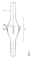
- Fig. 1 und 2
- einen Längsschnitt durch die Fixierzone einer Elektrodenvorrichtung in kontrahiertem bzw. expandiertem Zustand der Fixierzone,
- Fig. 3
- eine schematische Gesamtansicht einer Elektrodenvorrichtung,
- Fig. 4
- einen Detail-Axialschnitt der Elektrodenvorrichtung im Bereich der proximalen Druckmedium-Zuführung,
- Fig. 5
- eine Teil-Seitenansicht der Fixierzone eines Elektrodenkörpers mit Verankerungselementen an der Außenseite,
- Fig. 6 bis 19
- schematische Detail-Längsaxial-Schnitte der Fixierzone von Elektrodenvorrichtungen mit einer Faltenwurfkonfiguration in unterschiedlichen Ausführungsformen,
- Fig. 20
- eine Draufsicht auf ein bistabiles Kippelement zur Verwendung in der Fixierzone eines Elektrodenkörpers,
- Fig. 21 und 22
- schematische Seitenansichten zweier solcher Kippelemente in expandiertem bzw. kontrahiertem Zustand der Fixierzone, und
- Fig. 23 und 24
- Detail-Längsaxial-Schnitte durch die Fixierzone eines Elektrodenkörpers, der Kippelemente gemäß Fig. 20 bis 22 aufweist, in expandiertem bzw. kontrahiertem Zustand der Fixierzone.
- Fig. 1 and 2
- a longitudinal section through the fixing zone of an electrode device in the contracted or expanded state of the fixing zone,
- Fig. 3
- a schematic overall view of an electrode device,
- Fig. 4
- a detail axial section of the electrode device in the region of the proximal pressure medium supply,
- Fig. 5
- a partial side view of the fixing of an electrode body with anchoring elements on the outside,
- Fig. 6 to 19
- schematic detail longitudinal axial sections of the fixing zone of electrode devices with a drape configuration in different embodiments,
- Fig. 20
- a top view of a bistable tilting element for use in the fixing zone of an electrode body,
- FIGS. 21 and 22
- schematic side views of two such tilting elements in the expanded or contracted state of the fixing, and
- FIGS. 23 and 24
- Detail longitudinal axial sections through the fixing of an electrode body having tilting elements according to FIG. 20 to 22, in the expanded or contracted state of the fixing zone.
Wie aus Fig. 1 und 2 deutlich wird, weist eine implantierbare medizinische Elektrodenvorrichtung in Form eines als Ganzem mit 1 bezeichneten Herzkatheters einen langgestreckten, schlauchartigen Elektrodenkörper 2 auf, der vor dem distalen Ende 3 (Fig. 3) mit einer einige Millimeter langen Fixierzone 4 versehen ist. Im Inneren des Elektrodenkörpers 2 laufen in einem gesonderten Innenschlauch 5 die gewendelten Elektrodenzuleitungen 6, mit der die beispielsweise in Fig. 3 gezeigten Stimulationselektroden 7 mit Spannung versorgt werden.As can be seen from Figures 1 and 2, an implantable medical electrode device in the form of a cardiac catheter, indicated as a whole by 1, has an elongate, tube-
Im Bereich der Fixierzone 4 ist die Wandung 8 des Elektrodenkörpers 2 flexibler als in den angrenzenden restlichen Bereichen ausgebildet. Ferner ist darin eine stentartige, plastisch verformbare Stützstruktur 9 in das Wandungsmaterial eingebettet. Diese Stützstruktur 9 ist ein im Wesentlichen rohrförmiges, plastisch verformbares, expandierbares Streckmetall- oder Kunststoffformteil. Die Expansionskräfte dieser Stützstruktur 9 sind durch geeignete Materialwahl und Strukturierung der Stege 10 - etwa durch Abstimmung der Stegbreite, Steghöhe, der Form der Biegeschenkel usw. - auf die elastischen und geometrischen Eigenschaften des einbettenden Materials der Wandung 8 der Fixierzone 4 abzustimmen, die wiederum durch die Wandstärke und die Materialwahl, wie beispielsweise Latex, Silikon, Polyurethan, bestimmt ist.In the region of the fixing
Wie aus Fig. 3 deutlich wird, ist am proximalen Ende 11 des Herzkatheters 1 eine Zuführeinrichtung 12 um den Elektrodenkörper 2 herum vorgesehen, über die mittels einer Spritze 13 über die angeschlossene Einspeiseleitung 14 ein hydraulisches Druckmedium, wie beispielsweise physiologische Kochsalzlösung, in den als druckdichter Schlauch ausgebildeten Elektrodenkörper 2 mit einem Druck pH einpressbar ist. Das proximale Ende 11 des Herzkatheters 1 ist durch einen Anschlussstecker 15 für die einzelnen Stimulationselektroden 7 gebildet.As is clear from Fig. 3, at the
Die Zuführeinrichtung 12 ist in Fig. 4 dargestellt. Der Anschluss 16 der Einspeiseleitung 14 sitzt mittig in der Wand einer den Elektrodenkörper 2 umgebenden Zylinderhülse 17, zwischen deren Stirnöffnungen und dem Elektrodenkörper 2 jeweils O-Ring-Dichtungen 18 eingepasst sind. Diese werden von auf die Zylinderhülse 17 aufschraubbaren Klemmhülsen 47 zur Abdichtung beaufschlagt, sodass über den Anschluss 16 und eine Einspeiseöffnung 19 das Druckfluid in den Ringraum zwischen dem Elektrodenkörper 2 und dem Innenschlauch 5 eingepresst werden kann.The
Wie aus Fig. 1 und 2 deutlich wird, wird der Herzkatheter 1 beispielsweise in den Koronarsinus mit seinem distalen Ende 3 vorgeschoben, bis die gewünschte Position der Stimulationselektroden 7 erreicht ist. Die Röntgenüberwachbarkeit dieses Vorgangs ist durch eine entsprechende Auslegung der Stützstruktur 9 aus einem röntgensichtbaren Material, wie beispielsweise geeignet beschichtetem Kunststoff, Edelstahl, Platin-, Titan-Legierungen, Magnesium oder Gold verbesserbar.As is clear from FIGS. 1 and 2, the
Durch Beaufschlagen der Fixierzone 4 mit dem Druckfluid als Expansionsmittel wird dort die Stützstruktur 9 plastisch aufgeweitet und dehnt sich damit radial aus, wie in Fig. 2 erkennbar ist. Dies wird so lange fortgesetzt, bis die Fixierzone 4 mit ihrem erweiterten Durchmesser an der Gefäßinnenwand (hier nicht dargestellt) anliegt und damit den Herzkatheter 1 in dieser Position fixiert.By subjecting the fixing
Zu einer Umpositionierung oder Entfernung des Herzkatheters 1 wird das Druckfluid abgesaugt, wodurch ein Unterdruck entsteht, der dafür sorgt, dass die Fixierzone 4 sich wieder zusammenzieht und dabei die Stützstruktur 9 quasi kollabiert, womit wieder die in Fig. 1 gezeigte Konfiguration erreicht wird und der Herzkatheter 1 frei verschiebbar ist.For a repositioning or removal of the
Der Expansionsdurchmesser D in der Fixierzone 4 kann durch Kontrolle des eingebrachten Volumens des Druckfluids oder durch den angelegten Druck - auch bei einer pneumatischen Steuerung - direkt beeinflusst werden. Das Druckfluid kann dabei auch durch ein exzentrisches Zusatzlumen im Elektrodenkörper 2 oder durch einen äußeren, koaxial angeordneten Schlauch übertragen werden, wie in den Figuren im Einzelnen nicht dargestellt ist.The expansion diameter D in the fixing
Schließlich ist darauf hinzuweisen, dass durch eine geeignete Formgebung der eingebetteten Stützstruktur 9 auch eine axiale Verformbarkeit erreichbar ist, sodass der Herzkatheter 1 zur Platzierung in den Gefäßen auch im Bereich der Fixierzone 4 ausreichend flexibel bleibt.Finally, it should be pointed out that an axial deformability can also be achieved by suitable shaping of the embedded
Wie aus Fig. 5 deutlich wird, kann durch eine geeignete Strukturierung der Außenfläche der Fixierzone 4 eine zusätzliche Festlegung des Herzkatheters 1 erreicht werden. Dazu sind in einer weiteren Ausführungsform im Bereich der Fixierzone 4 an der Außenseite stegförmige Verankerungselemente 20 über den Umfang verteilt parallel zur Längsrichtung des Elektrodenkörpers 2 angebracht. In der nicht expandierten Konfiguration liegen diese Verankerungselemente 20 flach an der Außenseite des Herzkatheters 1 an, sodass eine problemlose Einführung gewährleistet ist. Durch das Expandieren der Fixierzone 4 spreizen sich die Verankerungselemente 20 ab, wie es in Fig. 5 gezeigt ist und beaufschlagen zusätzlich mechanisch die Innenwand des hier nicht gezeigten Gefäßes. Damit wird insbesondere eine deutlich größere Auszugssicherheit des Herzkatheters 1 erreicht. Die Verankerungselemente 20 können je nach Materialauswahl weich oder steif ausgelegt sein. Als Materialien kommen Elastomere, andere Kunststoffe oder Metalle in Frage.As is clear from FIG. 5, an additional definition of the
Die in Fig. 6 bis 19 gezeigten Ausführungsbeispiele des Herzkatheters 1 beruhen auf einem rein mechanischen Steuerungsprinzip. Dazu ist die Fixierzone 4 jeweils mit einer als Ganzem mit 21 bezeichneten Faltenwurfkonfiguration versehen, die zusammen mit einer koaxial zum Elektrodenkörper aufgebrachten Zug- oder Schubbeaufschlagung als Expansionsmittel agiert und im Folgenden anhand der einzelnen Figuren näher erläutert wird.The embodiments of the
So zeigt Fig. 6 eine Herabsetzung der Wandstärke des Elektrodenkörpers 2 im Bereich der Fixierzone 4. Wird nun nach Positionierung des Herzkatheters 1 ein nicht näher dargestellter, an der Spitze des Elektrodenkörpers 2 befestigter Zugdraht in proximaler Richtung relativ zum Elektrodenkörper 2 auf Zug beansprucht, so beult sich der Elektrodenkörper 2 im Bereich der Wandungsverdünnung aus und bildet eine radial nach außen abstehende Ringfalte 22 (Fig. 7). Diese ist im Querschnitt ballig und damit atraumatisch. Die Durchmesseraufweitung der Ringfalte 22 erfolgt so lange, bis letztere sicher an einer Gefäßwand anliegt und eine Verankerung des Herzkatheters 1 mit sich bringt.6 shows a reduction in the wall thickness of the
In Fig. 8 ist ein Ausführungsbeispiel gezeigt, in dem durch drei in axialer Richtung aneinandergereihte, schmalere Wandungsverdünnungen bei Zugbeaufschlagung des Zugdrahtes drei Ringfalten 22 in axialer Richtung aneinandergereiht entstehen.In Fig. 8, an embodiment is shown in which three
Für eine entsprechende Auslegung der Wandung 8 im Durchmesser bzw. variierende Flexibilität des Wandungsmaterials können die Ringfalten 22 auch nach dem Aufweiten ein Sägezahnprofil bilden, wie dies in Fig. 9 dargestellt ist. Damit ist die Haltekraft in Auszugsrichtung des Herzkatheters 1 größer als in Einschubrichtung.For a corresponding design of the
In der in Fig. 10 gezeigten Ausführungsform ist die Wandung 8 so ausgelegt, dass sich beim Expandieren mit Hilfe des (nicht gezeigten) Zugdrahtes die Ringfalten 22 übereinander schieben, sodass mehrere zentral gelegene Innenfalten 23 und mehrere peripher gelegene Außenfalten 24 entstehen. Damit beruht die Durchmesservergrößerung des Elektrodenkörpers 2 nicht nur auf einer reinen Faltenbildung, sondern auch auf einer Verdickung des Materials durch das Bilden von mehreren, vorzugsweise mindestens drei Lagen.In the embodiment shown in Fig. 10, the
Fig. 11 und 12 zeigt eine Ausführungsform, bei der eine einzige Ringfalte 22 gebildet wird, die durch in die Wandung 8 eingebrachte Verdickungen 25 sich so lagenweise übereinander schiebt, dass eine Verriegelung der Lagen erfolgt. Wird beim Zusammenschieben der Falte die Innenfalte 23 unter die Außenfalte 24 geschoben, schnappt die Verdickung 25 der Innenfalte 23 hinter die entsprechende Verdickung 25 der Außenfalte 24, wodurch die gebildete Konfiguration festgelegt wird.Fig. 11 and 12 shows an embodiment in which a single
Bei der in Fig. 13 dargestellten Ausführungsform sind am Rand der Fixierzone 4 wiederum über den Umfang verteilt stegartige Verankerungselemente 20 vorgesehen, die bei einem Aufweiten der Ringfalte 22 aufgespreizt werden und sich zusätzlich in der Gefäßwand verankern. Fig. 14 zeigt den entsprechenden Bereich des Herzkatheters 1 in gestrecktem Zustand, bei dem sich die Verankerungselemente 20 an den gestreckten Elektrodenkörper 2 anschmiegen.In the embodiment shown in FIG. 13, web-
Bei der in Fig. 15 gezeigten Ausführungsform ist der Elektrodenkörper 2 in der Fixierzone 4 hinsichtlich seiner Materialauswahl und des Wandungsdurchmessers so ausgelegt, dass die Flanken 26 der sich bildenden Ringfalten 22 versteift sind. Ist der Herzkatheter 1, wie in dieser Figur gezeigt, im Gefäß 27 positioniert, wird der nicht dargestellte Zugdraht betätigt und die Faltenbildung erfolgt, wie dies in Fig. 16 in einem Zwischenzustand gezeigt ist. In diesem Zustand ist das Gefäß 27 etwas überdehnt. Bei weiterer Betätigung des Zugdrahtes klappen die Ringfalten 22 wieder über die radial maximal ausgedehnte Konfiguration über, sodass die versteiften Flanken 26 übereinander liegen und den Herzkatheter 1 im Gefäß 27 fixieren (Fig. 17).In the embodiment shown in FIG. 15, the
Bei der in den Fig. 18 und 19 gezeigten Variante ist im Elektrodenkörper 2 im Bereich der Fixierzone 4 eine Spreizeinrichtung 28 vorgesehen, die die Faltenbildung unterstützt. Diese Spreizeinrichtung 28 weist einen im Elektrodenkörper 2 festgelegten Konus 29 auf, der mit einer distal davor gelagerten, vom Zugdraht 30 beaufschlagten Spreizhülse 31 kooperiert. Bei Beaufschlagung des Zugdrahtes 30 in proximaler Richtung untergreift der Konus 29 die Spreizarme 32 der Spreizhülse 31, die sich damit radial aufweiten und damit zur Bildung der Ringfalte 22 beitragen. Durch die Spreizeinrichtung 28 kann die Stabilität der Fixierung erhöht werden. Bei einer federnden Ausführung der Spreizarme 32 - wie auch der Verankerungselemente 20 - ist die Faltenbildung und das Ausklappen der Verankerungselemente 20 reversibel. Wie bereits angesprochen, kann die Faltenbildung sowohl durch Variation der Wandstärken des Elektrodenkörpers 2 in der Fixierzone 4 als auch durch eine Variation der Härtegrade des Materials bzw. durch Vorformungen mit Memory-Effekt optimiert werden.In the variant shown in FIGS. 18 and 19, a spreading
Wie in den Fig. 6 bis 19 nicht im Einzelnen dargestellt ist, kann das distale Ende der Fixierzone 4 mit einem Zugdraht oder Zugseil verbunden sein, das innerhalb des Elektrodenkörpers 2 verläuft und relativ dazu beweglich angeordnet ist. Das proximale Ende des Zugdrahtes reicht bis über das proximale Ende des Elektrodenkörpers 2 hinaus. Ein Ziehen am Zugdraht oder ein Festhalten des Zugdrahtes bei gleichzeitigem Nach-Vorne-Schieben des Elektrodenkörpers 2 wird ein Aufeinander-Zu-Bewegen des distalen und des proximalen Endes der Fixierzone 4 ermöglicht, was das Ausbeulen der Ringfalte 22 gegebenenfalls unter Bildung der Innen- und Außenfalten 23, 24 erzeugt. Ein Lösen der damit erfolgten Fixierung des Herzkatheters 1 ist durch ein Schieben am Zugdraht realisierbar, wenn dieser hinreichend steif ist. Alternativ dazu kann ein Stylett in den Elektrodenkörper 2 eingeführt werden, mit dem das distale Ende des flexiblen Bereichs wieder nach vorne geschoben wird. In kinematischer Umkehr kann der Zugdraht mit dem distalen Ende auch als Widerlager dienen, wenn der proximale Teil des Elektrodenkörpers 2 zurückgezogen wird. In jedem Fall wird dadurch ein Kontrahieren und Glätten der Falten und ein Strecken der Fixierzone 4 unter Freigabe des Herzkatheters 1 erfolgen.As is not shown in detail in FIGS. 6 to 19, the distal end of the fixing
In den Fig. 20 bis 24 schließlich ist eine weitere Variante für die Expansion und Kontraktion des Herzkatheters 1 im Bereich seiner Fixierzone 4 dargestellt. Basis davon ist das in Fig. 20 in Draufsicht gezeigte bistabile Kippelement 33, das aus zwei jeweils S-förmig gebogenen Schenkeln 34, 35 besteht. Diese werden spiegelverkehrt aufeinander gelegt und an den Kreuzungspunkten 36 miteinander vernietet. An einem endseitigen Kreuzungspunkt 36 ist ferner wieder ein Verankerungselement 37 in Form einer Blechlamelle angebracht, die in Richtung der die Kreuzungspunkte 36 verbindenden Hauptachse nach innen steht. Die beiden Schenkel 34, 35 bilden - wie Fig. 20 gut erkennen lässt - in Draufsicht die Form einer 8.Finally, FIGS. 20 to 24 show a further variant for the expansion and contraction of the
Wie aus den Fig. 21 und 22 hervorgeht, sind die Schenkel 34, 35 in Seitenansicht nicht eben, sondern durch eine Vernietung unter Spannung so aneinander gebunden, dass das Kippelement 33 auch entlang seiner Längsachse 38 S-förmig gebogen ist. Fig. 21 zeigt dabei zwei solche Kippelemente 33 in einer Konfiguration, die im in Fig. 23 und 24 gezeigten Anwendungsfall dem expandierten Zustand entspricht. Die die Verankerungselemente 37 tragenden Abschnitte der Schenkel 34, 35 sind dabei konvex, die verbleibenden Abschnitte konkav gebogen. Dies ist eine stabile Endlage, die durch Beaufschlagung der konkaven Abschnitte der Schenkel 34, 35 nach außen in die in Fig. 22 dargestellte zweite stabile Endlage umschnappbar ist. In dieser sind die die Verankerungselemente 37 tragenden Abschnitte der Schenkel 34, 35 konkav gebogen, während die verbleibenden Abschnitte nun konvex sind. Insgesamt ist das Kippelement 33 also zwischen einer konkav-konvexen und konvex-konkaven Konfiguration zur Überführung zwischen dem expandierten und dem kontrahierten Zustand umschnappbar.As is apparent from Figs. 21 and 22, the
Wie die Fig. 23 und 24 zeigen, ist das Kippelement 33 mit seinen Schenkeln 34, 35 in die Wandung 8 des Elektrodenkörpers 2 komplett eingebettet, sodass letzterer wiederum eine nach außen geschlossene Hülle bildet. Lediglich die Verankerungselemente 37 stehen aus der Wandung 8 nach außen hervor.As FIGS. 23 and 24 show, the tilting
Zur Implantierung eines entsprechenden Herzkatheters 1 werden die eingebetteten Kippelemente 33, wie dies in Fig. 23 gezeigt ist, in diejenige bistabile Endlage gebracht, in der die Verankerungselemente 37 durch konkave Formgebung der entsprechenden Abschnitte der Schenkel 34, 35 eingezogen sind. Anschließend wird ein deflatierter Katheterballon 39 als Expansionsmittel durch den Elektrodenkörper 2 bis unter diesen konkaven Abschnitt gezogen und aufgepumpt. Dadurch werden die entsprechenden Abschnitte der Schenkel 34, 35 nach außen gewölbt, die Kippelemente 33 springen dadurch in die in Fig. 24 gezeigte andere bistabile Endlage über, in der die Verankerungselemente 37 durch die konvexe Form der sie lagernden Abschnitte der Schenkel 34, 35 nach außen abstehen und für eine zuverlässige Verankerung des Herzkatheters 1 in einem nicht gezeigten Gefäß sorgen.For implanting a corresponding
Für die Lösung dieser Verankerung genügt es, einen deflatierten Ballon 39 zwischen den konkav gewölbten Abschnitten der Schenkel 34, 35 zu positionieren und den Ballon 39 wiederum aufzublasen, wie dies in Fig. 23 gezeigt ist. Die Kippelemente 33 springen damit wieder in die andere bistabile Endlage zurück, die in Fig. 23 gezeigt ist. Der Herzkatheter 1 ist dann problemlos herausziehbar oder umzupositionieren.For the solution of this anchoring, it is sufficient to position a deflated
Claims (14)
Applications Claiming Priority (1)
| Application Number | Priority Date | Filing Date | Title |
|---|---|---|---|
| DE102006011349A DE102006011349A1 (en) | 2006-03-11 | 2006-03-11 | Implantable medical electrode device, in particular cardiovascular pacemaker or defibrillator electrode device |
Publications (3)
| Publication Number | Publication Date |
|---|---|
| EP1832309A2 true EP1832309A2 (en) | 2007-09-12 |
| EP1832309A3 EP1832309A3 (en) | 2007-10-24 |
| EP1832309B1 EP1832309B1 (en) | 2009-06-03 |
Family
ID=38051987
Family Applications (1)
| Application Number | Title | Priority Date | Filing Date |
|---|---|---|---|
| EP07003085A Not-in-force EP1832309B1 (en) | 2006-03-11 | 2007-02-14 | Implantable medical electrode device, in particular cardiovascular pacemaker or defibrillator electrode device |
Country Status (4)
| Country | Link |
|---|---|
| US (1) | US7809447B2 (en) |
| EP (1) | EP1832309B1 (en) |
| AT (1) | ATE432733T1 (en) |
| DE (2) | DE102006011349A1 (en) |
Cited By (4)
| Publication number | Priority date | Publication date | Assignee | Title |
|---|---|---|---|---|
| WO2007143306A1 (en) * | 2006-06-02 | 2007-12-13 | Cardiac Pacemakers, Inc. | Cardiac lead having stiffening structures for fixation |
| US8442656B2 (en) | 2006-06-02 | 2013-05-14 | Cardiac Pacemakers, Inc. | Cardiac lead having implantable stiffening structures for fixation |
| EP2777761A1 (en) * | 2013-03-14 | 2014-09-17 | BIOTRONIK SE & Co. KG | Implantable electrode |
| EP2862594A1 (en) * | 2013-10-17 | 2015-04-22 | BIOTRONIK SE & Co. KG | Active, reversible fixing of CRT electrodes |
Families Citing this family (14)
| Publication number | Priority date | Publication date | Assignee | Title |
|---|---|---|---|---|
| US7983764B2 (en) * | 2005-08-12 | 2011-07-19 | Cardiac Pacemakers, Inc. | Co-radial lead with extendable/retractable fixation mechanism and apparatus therefor |
| US8825129B2 (en) * | 2010-03-05 | 2014-09-02 | Sri International | Indwelling nerve block catheters |
| WO2011163236A2 (en) | 2010-06-21 | 2011-12-29 | Zorion Medical, Inc. | Bioabsorbable implants |
| AU2011312739B2 (en) | 2010-09-28 | 2015-06-11 | The Board Of Trustees Of The Leland Stanford Junior University | Device and method for positioning an electrode in tissue |
| US9872981B2 (en) | 2010-09-28 | 2018-01-23 | Biotrace Medical, Inc. | Device and method for positioning an electrode in a body cavity |
| WO2012075311A2 (en) | 2010-12-01 | 2012-06-07 | Zorion Medical, Inc. | Magnesium-based absorbable implants |
| EP2701795B1 (en) | 2011-04-28 | 2020-12-09 | Interventional Autonomics Corporation | Neuromodulation systems for treating acute heart failure syndromes |
| JP6095658B2 (en) | 2011-07-11 | 2017-03-15 | インターベンショナル オートノミックス コーポレーション | System and method for neuromodulation therapy |
| US20130072995A1 (en) | 2011-07-11 | 2013-03-21 | Terrance Ransbury | Catheter system for acute neuromodulation |
| US9446240B2 (en) | 2011-07-11 | 2016-09-20 | Interventional Autonomics Corporation | System and method for neuromodulation |
| US8972027B2 (en) * | 2011-07-19 | 2015-03-03 | Shalom MANOVA | Implantable medical device including electrode element, anchoring element and elastic element |
| US9526887B2 (en) * | 2012-06-29 | 2016-12-27 | Nuvectra Corporation | Method of making a braided lead with imbedded fixation structures |
| AU2015255814B2 (en) | 2014-05-09 | 2018-12-06 | Merit Medical Systems, Inc. | Device and method for positioning an electrode in a body cavity |
| JP6632191B2 (en) * | 2015-01-08 | 2020-01-22 | アドリアカイム株式会社 | Nerve stimulation electrode |
Citations (6)
| Publication number | Priority date | Publication date | Assignee | Title |
|---|---|---|---|---|
| US5170802A (en) | 1991-01-07 | 1992-12-15 | Medtronic, Inc. | Implantable electrode for location within a blood vessel |
| EP0546414A1 (en) | 1991-12-12 | 1993-06-16 | Vitatron Medical B.V. | Pacing lead with improved anchor mechanism |
| WO1994007564A2 (en) | 1992-10-01 | 1994-04-14 | Cardiac Pacemakers, Inc. | Stent-type defibrillation electrode structures |
| US5411546A (en) | 1992-12-11 | 1995-05-02 | Siemens Elema Ab | Defibrillation electrode |
| WO1998042403A1 (en) | 1997-03-25 | 1998-10-01 | Intermedics Inc. | Cardiac lead for pacing or defibrillating the heart through the coronary sinus |
| US20060036307A1 (en) | 2004-08-16 | 2006-02-16 | Cardiac Pacemakers, Inc. | Lead assembly and methods including a push tube |
Family Cites Families (10)
| Publication number | Priority date | Publication date | Assignee | Title |
|---|---|---|---|---|
| DE2249690B2 (en) * | 1972-10-11 | 1976-11-25 | Kernforschungsanlage Jülich GmbH, 517OJuIiCh | SAFETY DEVICE FOR PLANTS UNDER PRESSURE |
| DE2305262A1 (en) * | 1973-02-02 | 1974-08-08 | Siemens Ag | ENDOCARD ELECTRODE |
| DE3783110D1 (en) * | 1986-09-23 | 1993-01-28 | Siemens Ag | HEART PACEMAKER. |
| DE3718139C1 (en) * | 1987-05-29 | 1988-12-08 | Strahlen Umweltforsch Gmbh | Cardiac catheter |
| US4913164A (en) * | 1988-09-27 | 1990-04-03 | Intermedics, Inc. | Extensible passive fixation mechanism for lead assembly of an implantable cardiac stimulator |
| FR2742058B1 (en) * | 1995-12-12 | 1998-03-06 | Ela Medical Sa | FOLDABLE ANCHOR BARS PROBES FOR AN IMPLANTED MEDICAL DEVICE, IN PARTICULAR FOR A HEART STIMULATOR |
| US5871483A (en) * | 1996-01-19 | 1999-02-16 | Ep Technologies, Inc. | Folding electrode structures |
| SE9802104D0 (en) * | 1998-06-12 | 1998-06-12 | Pacesetter Ab | Medical electrode device |
| DE19930237A1 (en) * | 1999-06-25 | 2000-12-28 | Biotronik Mess & Therapieg | Electrode arrangement |
| US6805707B1 (en) * | 2001-12-27 | 2004-10-19 | Advanced Cardiovascular Systems, Inc. | Stent with improved ring and link pattern |
-
2006
- 2006-03-11 DE DE102006011349A patent/DE102006011349A1/en not_active Withdrawn
-
2007
- 2007-02-14 DE DE502007000797T patent/DE502007000797D1/en active Active
- 2007-02-14 AT AT07003085T patent/ATE432733T1/en active
- 2007-02-14 EP EP07003085A patent/EP1832309B1/en not_active Not-in-force
- 2007-03-08 US US11/683,900 patent/US7809447B2/en not_active Expired - Fee Related
Patent Citations (6)
| Publication number | Priority date | Publication date | Assignee | Title |
|---|---|---|---|---|
| US5170802A (en) | 1991-01-07 | 1992-12-15 | Medtronic, Inc. | Implantable electrode for location within a blood vessel |
| EP0546414A1 (en) | 1991-12-12 | 1993-06-16 | Vitatron Medical B.V. | Pacing lead with improved anchor mechanism |
| WO1994007564A2 (en) | 1992-10-01 | 1994-04-14 | Cardiac Pacemakers, Inc. | Stent-type defibrillation electrode structures |
| US5411546A (en) | 1992-12-11 | 1995-05-02 | Siemens Elema Ab | Defibrillation electrode |
| WO1998042403A1 (en) | 1997-03-25 | 1998-10-01 | Intermedics Inc. | Cardiac lead for pacing or defibrillating the heart through the coronary sinus |
| US20060036307A1 (en) | 2004-08-16 | 2006-02-16 | Cardiac Pacemakers, Inc. | Lead assembly and methods including a push tube |
Cited By (4)
| Publication number | Priority date | Publication date | Assignee | Title |
|---|---|---|---|---|
| WO2007143306A1 (en) * | 2006-06-02 | 2007-12-13 | Cardiac Pacemakers, Inc. | Cardiac lead having stiffening structures for fixation |
| US8442656B2 (en) | 2006-06-02 | 2013-05-14 | Cardiac Pacemakers, Inc. | Cardiac lead having implantable stiffening structures for fixation |
| EP2777761A1 (en) * | 2013-03-14 | 2014-09-17 | BIOTRONIK SE & Co. KG | Implantable electrode |
| EP2862594A1 (en) * | 2013-10-17 | 2015-04-22 | BIOTRONIK SE & Co. KG | Active, reversible fixing of CRT electrodes |
Also Published As
| Publication number | Publication date |
|---|---|
| EP1832309A3 (en) | 2007-10-24 |
| ATE432733T1 (en) | 2009-06-15 |
| US20070213798A1 (en) | 2007-09-13 |
| DE102006011349A1 (en) | 2007-09-13 |
| DE502007000797D1 (en) | 2009-07-16 |
| US7809447B2 (en) | 2010-10-05 |
| EP1832309B1 (en) | 2009-06-03 |
Similar Documents
| Publication | Publication Date | Title |
|---|---|---|
| EP1832309A2 (en) | Implantable medical electrode device, in particular cardiovascular pacemaker or defibrillator electrode device | |
| DE69434819T2 (en) | INSERTING A PROSTHESIS | |
| DE69635402T2 (en) | Guide unit with internal guidewire made of a shape memory alloy | |
| DE60309843T2 (en) | DEVICE FOR ANCHORING ENDOLUMINAL PROTESTS | |
| EP1200018B1 (en) | Insertion catheter for vascular prostheses | |
| DE69633265T2 (en) | Guide wire unit | |
| DE69935075T2 (en) | BENDING TRANSMYOKARDIMPLANTAT FOR THE INDUCTION OF ANGIOGENESIS | |
| DE3250058C2 (en) | ||
| DE60115239T2 (en) | DEVICE FOR INTRODUCING A STENT | |
| EP0999806B1 (en) | Intraluminal implantation device | |
| DE69634791T2 (en) | Stent with multiple anchoring | |
| DE602004010344T2 (en) | Catheter without balloon for inserting a stent | |
| DE10334868A1 (en) | Implantable device as a replacement organ valve | |
| DE2119172B2 (en) | BALLOON CATHETER AND METHOD OF ITS MANUFACTURING | |
| DE102015111205A1 (en) | Treatment device of a bloodstream | |
| EP2884946A2 (en) | Implantable device for use in the human and/or animal body to replace an organ valve | |
| DE3342798T1 (en) | Prosthesis with an expandable or contractible tubular body | |
| WO2009077845A2 (en) | Support implant, in particular a stent, and implantation catheter for the support implant | |
| EP3209248A2 (en) | Stent for splinting a vein, and system for putting in place a stent | |
| WO2013068127A1 (en) | Arrangement for implanting stent elements in or around a hollow organ | |
| EP2775968A1 (en) | Arrangement for implanting stent elements in or around a hollow organ | |
| WO1995015130A1 (en) | Vascular prosthesis | |
| EP3400914A1 (en) | Handle for a catheter and corresponding catheter | |
| DE69633134T2 (en) | EXPANDABLE, TILTABLE STENT FOR SURGICAL USE FOR EXPANDING A BODY LIQUID | |
| DE19838414B4 (en) | Implantation device for self-expanding stents |
Legal Events
| Date | Code | Title | Description |
|---|---|---|---|
| PUAI | Public reference made under article 153(3) epc to a published international application that has entered the european phase |
Free format text: ORIGINAL CODE: 0009012 |
|
| AK | Designated contracting states |
Kind code of ref document: A2 Designated state(s): AT BE BG CH CY CZ DE DK EE ES FI FR GB GR HU IE IS IT LI LT LU LV MC NL PL PT RO SE SI SK TR |
|
| AX | Request for extension of the european patent |
Extension state: AL BA HR MK YU |
|
| PUAL | Search report despatched |
Free format text: ORIGINAL CODE: 0009013 |
|
| AK | Designated contracting states |
Kind code of ref document: A3 Designated state(s): AT BE BG CH CY CZ DE DK EE ES FI FR GB GR HU IE IS IT LI LT LU LV MC NL PL PT RO SE SI SK TR |
|
| AX | Request for extension of the european patent |
Extension state: AL BA HR MK YU |
|
| 17P | Request for examination filed |
Effective date: 20080329 |
|
| 17Q | First examination report despatched |
Effective date: 20080508 |
|
| AKX | Designation fees paid |
Designated state(s): AT BE BG CH CY CZ DE DK EE ES FI FR GB GR HU IE IS IT LI LT LU LV MC NL PL PT RO SE SI SK TR |
|
| GRAP | Despatch of communication of intention to grant a patent |
Free format text: ORIGINAL CODE: EPIDOSNIGR1 |
|
| GRAS | Grant fee paid |
Free format text: ORIGINAL CODE: EPIDOSNIGR3 |
|
| GRAA | (expected) grant |
Free format text: ORIGINAL CODE: 0009210 |
|
| AK | Designated contracting states |
Kind code of ref document: B1 Designated state(s): AT BE BG CH CY CZ DE DK EE ES FI FR GB GR HU IE IS IT LI LT LU LV MC NL PL PT RO SE SI SK TR |
|
| REG | Reference to a national code |
Ref country code: GB Ref legal event code: FG4D Free format text: NOT ENGLISH |
|
| REG | Reference to a national code |
Ref country code: CH Ref legal event code: EP |
|
| REG | Reference to a national code |
Ref country code: IE Ref legal event code: FG4D Free format text: LANGUAGE OF EP DOCUMENT: GERMAN |
|
| REF | Corresponds to: |
Ref document number: 502007000797 Country of ref document: DE Date of ref document: 20090716 Kind code of ref document: P |
|
| REG | Reference to a national code |
Ref country code: SE Ref legal event code: TRGR |
|
| PG25 | Lapsed in a contracting state [announced via postgrant information from national office to epo] |
Ref country code: FI Free format text: LAPSE BECAUSE OF FAILURE TO SUBMIT A TRANSLATION OF THE DESCRIPTION OR TO PAY THE FEE WITHIN THE PRESCRIBED TIME-LIMIT Effective date: 20090603 Ref country code: LT Free format text: LAPSE BECAUSE OF FAILURE TO SUBMIT A TRANSLATION OF THE DESCRIPTION OR TO PAY THE FEE WITHIN THE PRESCRIBED TIME-LIMIT Effective date: 20090603 |
|
| NLV1 | Nl: lapsed or annulled due to failure to fulfill the requirements of art. 29p and 29m of the patents act | ||
| PG25 | Lapsed in a contracting state [announced via postgrant information from national office to epo] |
Ref country code: PL Free format text: LAPSE BECAUSE OF FAILURE TO SUBMIT A TRANSLATION OF THE DESCRIPTION OR TO PAY THE FEE WITHIN THE PRESCRIBED TIME-LIMIT Effective date: 20090603 Ref country code: NL Free format text: LAPSE BECAUSE OF FAILURE TO SUBMIT A TRANSLATION OF THE DESCRIPTION OR TO PAY THE FEE WITHIN THE PRESCRIBED TIME-LIMIT Effective date: 20090603 Ref country code: SI Free format text: LAPSE BECAUSE OF FAILURE TO SUBMIT A TRANSLATION OF THE DESCRIPTION OR TO PAY THE FEE WITHIN THE PRESCRIBED TIME-LIMIT Effective date: 20090603 Ref country code: LV Free format text: LAPSE BECAUSE OF FAILURE TO SUBMIT A TRANSLATION OF THE DESCRIPTION OR TO PAY THE FEE WITHIN THE PRESCRIBED TIME-LIMIT Effective date: 20090603 |
|
| PG25 | Lapsed in a contracting state [announced via postgrant information from national office to epo] |
Ref country code: IS Free format text: LAPSE BECAUSE OF FAILURE TO SUBMIT A TRANSLATION OF THE DESCRIPTION OR TO PAY THE FEE WITHIN THE PRESCRIBED TIME-LIMIT Effective date: 20091003 Ref country code: CZ Free format text: LAPSE BECAUSE OF FAILURE TO SUBMIT A TRANSLATION OF THE DESCRIPTION OR TO PAY THE FEE WITHIN THE PRESCRIBED TIME-LIMIT Effective date: 20090603 Ref country code: RO Free format text: LAPSE BECAUSE OF FAILURE TO SUBMIT A TRANSLATION OF THE DESCRIPTION OR TO PAY THE FEE WITHIN THE PRESCRIBED TIME-LIMIT Effective date: 20090603 Ref country code: EE Free format text: LAPSE BECAUSE OF FAILURE TO SUBMIT A TRANSLATION OF THE DESCRIPTION OR TO PAY THE FEE WITHIN THE PRESCRIBED TIME-LIMIT Effective date: 20090603 Ref country code: ES Free format text: LAPSE BECAUSE OF FAILURE TO SUBMIT A TRANSLATION OF THE DESCRIPTION OR TO PAY THE FEE WITHIN THE PRESCRIBED TIME-LIMIT Effective date: 20090914 |
|
| PG25 | Lapsed in a contracting state [announced via postgrant information from national office to epo] |
Ref country code: SK Free format text: LAPSE BECAUSE OF FAILURE TO SUBMIT A TRANSLATION OF THE DESCRIPTION OR TO PAY THE FEE WITHIN THE PRESCRIBED TIME-LIMIT Effective date: 20090603 |
|
| PG25 | Lapsed in a contracting state [announced via postgrant information from national office to epo] |
Ref country code: BG Free format text: LAPSE BECAUSE OF FAILURE TO SUBMIT A TRANSLATION OF THE DESCRIPTION OR TO PAY THE FEE WITHIN THE PRESCRIBED TIME-LIMIT Effective date: 20090903 Ref country code: PT Free format text: LAPSE BECAUSE OF FAILURE TO SUBMIT A TRANSLATION OF THE DESCRIPTION OR TO PAY THE FEE WITHIN THE PRESCRIBED TIME-LIMIT Effective date: 20091003 |
|
| PLBE | No opposition filed within time limit |
Free format text: ORIGINAL CODE: 0009261 |
|
| STAA | Information on the status of an ep patent application or granted ep patent |
Free format text: STATUS: NO OPPOSITION FILED WITHIN TIME LIMIT |
|
| PG25 | Lapsed in a contracting state [announced via postgrant information from national office to epo] |
Ref country code: DK Free format text: LAPSE BECAUSE OF FAILURE TO SUBMIT A TRANSLATION OF THE DESCRIPTION OR TO PAY THE FEE WITHIN THE PRESCRIBED TIME-LIMIT Effective date: 20090603 |
|
| 26N | No opposition filed |
Effective date: 20100304 |
|
| BERE | Be: lapsed |
Owner name: BIOTRONIK CRM PATENT A.G. Effective date: 20100228 |
|
| PG25 | Lapsed in a contracting state [announced via postgrant information from national office to epo] |
Ref country code: MC Free format text: LAPSE BECAUSE OF NON-PAYMENT OF DUE FEES Effective date: 20100301 Ref country code: GR Free format text: LAPSE BECAUSE OF FAILURE TO SUBMIT A TRANSLATION OF THE DESCRIPTION OR TO PAY THE FEE WITHIN THE PRESCRIBED TIME-LIMIT Effective date: 20090904 |
|
| PG25 | Lapsed in a contracting state [announced via postgrant information from national office to epo] |
Ref country code: BE Free format text: LAPSE BECAUSE OF NON-PAYMENT OF DUE FEES Effective date: 20100228 |
|
| PG25 | Lapsed in a contracting state [announced via postgrant information from national office to epo] |
Ref country code: IT Free format text: LAPSE BECAUSE OF FAILURE TO SUBMIT A TRANSLATION OF THE DESCRIPTION OR TO PAY THE FEE WITHIN THE PRESCRIBED TIME-LIMIT Effective date: 20090603 |
|
| PG25 | Lapsed in a contracting state [announced via postgrant information from national office to epo] |
Ref country code: CY Free format text: LAPSE BECAUSE OF FAILURE TO SUBMIT A TRANSLATION OF THE DESCRIPTION OR TO PAY THE FEE WITHIN THE PRESCRIBED TIME-LIMIT Effective date: 20090603 |
|
| PG25 | Lapsed in a contracting state [announced via postgrant information from national office to epo] |
Ref country code: HU Free format text: LAPSE BECAUSE OF FAILURE TO SUBMIT A TRANSLATION OF THE DESCRIPTION OR TO PAY THE FEE WITHIN THE PRESCRIBED TIME-LIMIT Effective date: 20091204 Ref country code: LU Free format text: LAPSE BECAUSE OF NON-PAYMENT OF DUE FEES Effective date: 20100214 |
|
| PG25 | Lapsed in a contracting state [announced via postgrant information from national office to epo] |
Ref country code: TR Free format text: LAPSE BECAUSE OF FAILURE TO SUBMIT A TRANSLATION OF THE DESCRIPTION OR TO PAY THE FEE WITHIN THE PRESCRIBED TIME-LIMIT Effective date: 20090603 |
|
| REG | Reference to a national code |
Ref country code: AT Ref legal event code: MM01 Ref document number: 432733 Country of ref document: AT Kind code of ref document: T Effective date: 20120214 |
|
| PGFP | Annual fee paid to national office [announced via postgrant information from national office to epo] |
Ref country code: GB Payment date: 20130219 Year of fee payment: 7 Ref country code: SE Payment date: 20130219 Year of fee payment: 7 |
|
| PG25 | Lapsed in a contracting state [announced via postgrant information from national office to epo] |
Ref country code: AT Free format text: LAPSE BECAUSE OF NON-PAYMENT OF DUE FEES Effective date: 20120214 |
|
| REG | Reference to a national code |
Ref country code: SE Ref legal event code: EUG |
|
| GBPC | Gb: european patent ceased through non-payment of renewal fee |
Effective date: 20140214 |
|
| PG25 | Lapsed in a contracting state [announced via postgrant information from national office to epo] |
Ref country code: SE Free format text: LAPSE BECAUSE OF NON-PAYMENT OF DUE FEES Effective date: 20140215 |
|
| PG25 | Lapsed in a contracting state [announced via postgrant information from national office to epo] |
Ref country code: GB Free format text: LAPSE BECAUSE OF NON-PAYMENT OF DUE FEES Effective date: 20140214 |
|
| REG | Reference to a national code |
Ref country code: DE Ref legal event code: R082 Ref document number: 502007000797 Country of ref document: DE Representative=s name: RANDOLL, SOEREN, DIPL.-CHEM. UNIV. DR. RER. NA, DE |
|
| REG | Reference to a national code |
Ref country code: FR Ref legal event code: PLFP Year of fee payment: 10 |
|
| PGFP | Annual fee paid to national office [announced via postgrant information from national office to epo] |
Ref country code: FR Payment date: 20160222 Year of fee payment: 10 |
|
| PGFP | Annual fee paid to national office [announced via postgrant information from national office to epo] |
Ref country code: CH Payment date: 20170221 Year of fee payment: 11 Ref country code: DE Payment date: 20170223 Year of fee payment: 11 |
|
| PGFP | Annual fee paid to national office [announced via postgrant information from national office to epo] |
Ref country code: IE Payment date: 20170223 Year of fee payment: 11 |
|
| REG | Reference to a national code |
Ref country code: FR Ref legal event code: ST Effective date: 20171031 |
|
| PG25 | Lapsed in a contracting state [announced via postgrant information from national office to epo] |
Ref country code: FR Free format text: LAPSE BECAUSE OF NON-PAYMENT OF DUE FEES Effective date: 20170228 |
|
| REG | Reference to a national code |
Ref country code: DE Ref legal event code: R082 Ref document number: 502007000797 Country of ref document: DE Ref country code: DE Ref legal event code: R081 Ref document number: 502007000797 Country of ref document: DE Owner name: BIOTRONIK SE & CO. KG, DE Free format text: FORMER OWNER: BIOTRONIK CRM PATENT AG, BAAR, CH |
|
| REG | Reference to a national code |
Ref country code: DE Ref legal event code: R119 Ref document number: 502007000797 Country of ref document: DE |
|
| REG | Reference to a national code |
Ref country code: CH Ref legal event code: PL |
|
| REG | Reference to a national code |
Ref country code: IE Ref legal event code: MM4A |
|
| PG25 | Lapsed in a contracting state [announced via postgrant information from national office to epo] |
Ref country code: CH Free format text: LAPSE BECAUSE OF NON-PAYMENT OF DUE FEES Effective date: 20180228 Ref country code: LI Free format text: LAPSE BECAUSE OF NON-PAYMENT OF DUE FEES Effective date: 20180228 |
|
| PG25 | Lapsed in a contracting state [announced via postgrant information from national office to epo] |
Ref country code: IE Free format text: LAPSE BECAUSE OF NON-PAYMENT OF DUE FEES Effective date: 20180214 Ref country code: DE Free format text: LAPSE BECAUSE OF NON-PAYMENT OF DUE FEES Effective date: 20180901 |