EP1834610A1 - Handle for long self expanding stent - Google Patents
Handle for long self expanding stent Download PDFInfo
- Publication number
- EP1834610A1 EP1834610A1 EP07005394A EP07005394A EP1834610A1 EP 1834610 A1 EP1834610 A1 EP 1834610A1 EP 07005394 A EP07005394 A EP 07005394A EP 07005394 A EP07005394 A EP 07005394A EP 1834610 A1 EP1834610 A1 EP 1834610A1
- Authority
- EP
- European Patent Office
- Prior art keywords
- stent
- sheath
- delivery system
- handle
- pushrod
- Prior art date
- Legal status (The legal status is an assumption and is not a legal conclusion. Google has not performed a legal analysis and makes no representation as to the accuracy of the status listed.)
- Withdrawn
Links
Images

Classifications
-
- A—HUMAN NECESSITIES
- A61—MEDICAL OR VETERINARY SCIENCE; HYGIENE
- A61F—FILTERS IMPLANTABLE INTO BLOOD VESSELS; PROSTHESES; DEVICES PROVIDING PATENCY TO, OR PREVENTING COLLAPSING OF, TUBULAR STRUCTURES OF THE BODY, e.g. STENTS; ORTHOPAEDIC, NURSING OR CONTRACEPTIVE DEVICES; FOMENTATION; TREATMENT OR PROTECTION OF EYES OR EARS; BANDAGES, DRESSINGS OR ABSORBENT PADS; FIRST-AID KITS
- A61F2/00—Filters implantable into blood vessels; Prostheses, i.e. artificial substitutes or replacements for parts of the body; Appliances for connecting them with the body; Devices providing patency to, or preventing collapsing of, tubular structures of the body, e.g. stents
- A61F2/95—Instruments specially adapted for placement or removal of stents or stent-grafts
- A61F2/9517—Instruments specially adapted for placement or removal of stents or stent-grafts handle assemblies therefor
-
- A—HUMAN NECESSITIES
- A61—MEDICAL OR VETERINARY SCIENCE; HYGIENE
- A61F—FILTERS IMPLANTABLE INTO BLOOD VESSELS; PROSTHESES; DEVICES PROVIDING PATENCY TO, OR PREVENTING COLLAPSING OF, TUBULAR STRUCTURES OF THE BODY, e.g. STENTS; ORTHOPAEDIC, NURSING OR CONTRACEPTIVE DEVICES; FOMENTATION; TREATMENT OR PROTECTION OF EYES OR EARS; BANDAGES, DRESSINGS OR ABSORBENT PADS; FIRST-AID KITS
- A61F2250/00—Special features of prostheses classified in groups A61F2/00 - A61F2/26 or A61F2/82 or A61F9/00 or A61F11/00 or subgroups thereof
- A61F2250/0058—Additional features; Implant or prostheses properties not otherwise provided for
- A61F2250/0065—Additional features; Implant or prostheses properties not otherwise provided for telescopic
Definitions
- the present invention relates to an intra-vascular device and method. More particularly, the present invention relates to a device for deployment of a stent for treatment of luminal, i.e., intra-vascular, diseases.
- a self-expanding stent was restrained within a sheath. After positioning of the stent at the desired location via fluoroscopic guidance, the physician retracted the sheath to deploy the stent, i.e., to expose the stent and allow it to self-expand. To completely deploy the stent, the physician had to retract the sheath over the entire length of the stent, which was relatively cumbersome and typically required the use of both hands or repeated motion of the physician in the case of long self-expanding stents.
- FIG. 1 is a partially cutaway delivery system 100 for deploying a stent 102 in accordance with the prior art.
- Stent 102 is a radially self-expanding stent.
- Delivery system 100 includes a pushrod 104 and a sheath 106, sometimes called a catheter sheath.
- Pushrod 104 includes a distal end 104D and a proximal end 104P.
- Stent 102 is placed over distal end 104D of pushrod 104.
- distal end 104D further includes radiopaque markers that allow the location of distal end 104D and stent 102 to be precisely tracked.
- Proximal end 104P of pushrod 104 terminates within and is mounted to a handle 112 or extends through handle 112 and out a port 114 of handle 112.
- pushrod 104 is a hollow tube and includes a guide wire lumen.
- a guide wire 116 extends through pushrod 104 and extends out distal end 104D.
- Guide wire 116 further extends through handle 112 and out port 114.
- Sheath 106 includes a distal end 106D and a proximal end 106P. Prior to deployment, stent 102 is radially compressed and restrained within distal end 106D of sheath 106. Proximal end 106P of sheath 106 extends into handle 112. Proximal end 106P of sheath 106 is coupled to an actuation button 118, sometimes called a thumb slider, of handle 112. Sheath 106 is a hollow tube and includes a pushrod lumen. Pushrod 104 extends through sheath 106.
- stent 102 is placed over distal end 104D of pushrod 104 and is radially compressed and restrained within distal end 106D of sheath 106. Stent 102 is introduced intra-vascularly and guided to the treatment site, e.g., an aneurysm.
- stent 102 is self-expandable and as sheath 106 is retracted, stent 102 self-expands and is permanently deployed, e.g., anchored within a lumen of a patient.
- the guiding of a stent and deployment of a self-expanding stent are well known to those of skill in the art.
- sheath 106 During deployment, sheath 106 must move the entire linear length X of stent 102 to completely uncover and thus deploy stent 102. Since actuation button 118 is connected to and moves sheath 106, actuation button 118 must also be moved the linear length X to retract sheath 106 over the entire linear length X of stent 102 as actuation button 118 and sheath 106 move in a strictly linear 1:1 motion.
- stent 102 is a long self-expanding stent
- length X is substantial, e.g., 200 mm or more. Accordingly, to accommodate the long travel of actuation button 118, handle 112 must also be very long and at least linear length X. However, long handles are cumbersome and difficult to manipulate.
- a stent delivery system includes a handle having a housing and a spool.
- a pushrod has a proximal end connected to the housing of the handle.
- a stent is located over a distal end of the pushrod, wherein the handle has a linear length less than a linear length of the stent.
- a sheath constrains the stent at a distal end of the sheath.
- a retraction wire is connected to a proximal end of the sheath and to the spool.
- the handle can be much shorter than the stent.
- the handle has a linear length less than the linear length, e.g., 200 mm or more, of the stent. Since the handle is short, the handle is not cumbersome and is easy to manipulate.
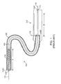
- FIG. 1 is a partially cutaway delivery system for deploying a stent in accordance with the prior art
- FIG. 2 is a partially cutaway delivery system for deploying a stent in accordance with one embodiment of the present invention.
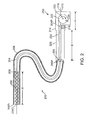
- FIG. 3 is a partially cutaway delivery system having a telescoping strain relief in accordance with one embodiment of the present invention.
- a stent delivery system 200 (FIG. 2) includes a handle 212 having a housing 214 and a spool 222.
- a pushrod 204 has a proximal end 204P connected to housing 214 of handle 212.
- a stent 202 is shown located over a distal end 204D of pushrod 204 (alternately, the stent could be located beyond the distal end of a pushrod), wherein handle 212 has a linear length Y less than a linear length X of stent 202.
- a sheath 206 constrains stent 202 at a distal end 206D of sheath 206.
- a retraction wire 224 is connected to a proximal end 206P of sheath 206 and to spool 222.
- handle 212 can be much shorter than stent 202.
- handle 212 has a linear length Y less than linear length X, e.g., 200 mm or more, of stent 202. Since handle 212 is short, handle 212 is not cumbersome and easy to manipulate.
- FIG. 2 is a partially cutaway delivery system 200 for deploying a stent 202 in accordance with one embodiment of the present invention.
- Stent 202 is a radially self-expanding stent having a linear length X, e.g., 200 mm or more.
- Delivery system 200 includes a pushrod 204 and a sheath 206, sometimes called a catheter sheath.
- Pushrod 204 sometimes called an inner member or inner shaft, includes a distal end 204D and a proximal end 204P.
- the proximal end of a delivery system is referenced with respect to the operator's handle while the proximal end of a stent is referenced with respect to the end closest to the heart via the length of blood traveled from the heart.
- Stent 202 is placed over distal end 204D of pushrod 204.
- distal end 204D further includes radiopaque markers that allow the location of distal end 204D and stent 202 to be precisely tracked.
- Pushrod 204 includes a stop 208 or other structures to prevent stent 202 from being moved proximally during retraction of sheath 206 as discussed further below.
- Proximal end 204P of pushrod 204 terminates within and is mounted to a handle 212. More particularly, handle 212 includes a housing 214. Connected to, or integral with, housing 214 is a pushrod anchor 216. Proximal end 204P of pushrod 204 is connected to pushrod anchor 216 and thus to housing 214. Accordingly, pushrod 204 does not move relative to housing 214 of handle 212.
- pushrod 204 is a hollow tube and includes a guide wire lumen.
- a guide wire 218 extends through pushrod 204 and extends out distal end 204D.
- Guide wire 218 further extends through handle 212 between a spool 222 and housing 214 and out of a guide wire port 220 of housing 214 of handle 212.
- Sheath 206 includes a distal end 206D and a proximal end 206P.
- stent 202 Prior to deployment, stent 202 is radially compressed and restrained within distal end 206D of sheath 206.
- Proximal end 206P of sheath 206 terminates adjacent to handle 212. More particularly, proximal end 206P is located at least a linear length X from pushrod anchor 216 allowing proximal end 206P and thus sheath 206 to be retracted at least linear length X.
- Handle 212 further includes spool 222 coupled to housing 214. More particularly, spool 222 rotates on an axle 223 extending through spool 222 and coupled to housing 214.
- a retraction wire 224 is connected to and extends between proximal end 206P of sheath 206 and spool 222.
- retraction wire 224 is glued, welded, screwed to, or otherwise mounted to proximal end 206P of sheath 206 at a bond 225 between retraction wire 224 and proximal end 206P of sheath 206.
- Spool 222 sometimes called a coil, provides a means for retracting retraction wire 224 and thus for retracting sheath 206.
- spool 222 includes a spool knob 226 that is rotated by the physician thus rotating spool 222 around axle 223. As spool 222 rotates, retraction wire 224 is wound into spool 222 and thus retracted.
- strain relief 228 relieves strain as it provides a gradual transition among the stiffness of the pushrod 204, sheath 206 and handle 212.
- strain relief 228 extends from handle 212 a distance sufficient to overlap proximal end 206P of sheath 206. More particularly, proximal end 206P of sheath 206 is located inside of strain relief 228.
- Sheath 206 is a hollow tube which acts as a pushrod lumen. Pushrod 204 extends through sheath 206.
- stent 202 is placed over distal end 204D (or alternately beyond the end, both configurations are considered near the distal end of the pushrod) of pushrod 204 and is radially compressed and restrained within distal end 206D of sheath 206.
- Stent 202 is introduced intra-vascularly and guided to the treatment site, e.g., a narrowing of an artery.
- sheath 206 is retracted by rotation of spool 222.
- spool 222 is rotated around axle 223 by rotation of knob 226 by the physician thus deploying stent 202.
- stent 202 is self-expandable and as sheath 206 is retracted, stent 202 self-expands as it is uncovered and is permanently deployed, e.g., anchored within a lumen of a patient.
- sheath 206 moves (is retracted) at least the entire length X of stent 202 to completely uncover and thus deploy stent 202. Since retraction of sheath 206 is accomplish by winding (coiling) retraction wire 224 around spool 222, handle 212 can be much shorter than stent 202. Illustratively, handle 212 has a linear length Y less than linear length X of stent 202. Since handle 212 is short, handle 212 is not cumbersome and is easy to manipulate.
- FIG. 3 is a partially cutaway delivery system 200A having a telescoping strain relief 228A in accordance with one embodiment of the present invention.
- Delivery system 200A of FIG. 3 is substantially similar to delivery system 200 of FIG. 2 and only the significant differences between delivery system 200A and delivery system 200 are discussed below. Specifically, pushrod 204A, sheath 206A, handle 212A, housing 214A, pushrod anchor 216A, guide wire 218A, guide wire port 220A, spool 222A, axle 223A, retraction wire 224A, bond 225A, knob 226A of delivery system 200A of FIG.
- FIG. 3 are similar to pushrod 204, sheath 206, handle 212, housing 214, pushrod anchor 216, guide wire 218, guide wire port 220, spool 222, axle 223, retraction wire 224, bond 225, knob 226 of delivery system 200 of FIG. 2, respectively, and so are not discussed further.
- Telescoping strain relief 228A is telescoping and includes cylindrical sections 302, 304, 306 of decreasing diameter. Specifically, cylindrical section 302 adjacent handle 212A has the greatest diameter D1 of cylindrical sections 302, 304, 306. Conversely, cylindrical section 306 is furthest away from handle 212 and has the smallest diameter D3 of cylindrical sections 302, 304, 306. Cylindrical section 304 is between cylindrical sections 302, 306 and has a diameter D2 smaller than diameter D1 of cylindrical section 302 and larger than diameter D3 of cylindrical section 306.
- Cylindrical sections 302, 304, 306 slide one within another to allow telescopic strain relief 228A to be telescoped to and from handle 212A.
- telescopic strain relief 228A is fully extended, sometimes called telescoped from, handle 212A.
- the physician grasps and pulls telescoping strain relief 228A from housing 214A thus telescoping and extending telescopic strain relief 228.
- telescopic strain relief 228A, and, more particularly, cylindrical section 306 extends over proximal end 206P of sheath 206A.
- cylindrical sections 302, 304, 306 include lips or other features to prevent cylindrical sections 302, 304, 306 from being separated from one another and from housing 214A.
- cylindrical section 302 includes proximal and distal lips 302PL, 302DL
- cylindrical section 304 includes proximal and distal lips 304PL, 304DL
- cylindrical section 306 includes a proximal lip 306PL.
- Proximal lip 302PL of cylindrical section 302 catches on housing 214A preventing cylindrical section 302 from being separated from housing 214A.
- Proximal lip 304PL of cylindrical section 304 catches on distal lip 302DL of cylindrical section 302 preventing cylindrical section 304 from being separated from cylindrical section 302.
- Proximal lip 306PL of cylindrical section 306 catches on distal lip 304DL of cylindrical section 304 preventing cylindrical section 306 from being separated from cylindrical section 304.
- cylindrical sections having lips to prevent the cylindrical sections from being separated from one another are discussed above and illustrated in FIG. 3, in other examples, other means are used to prevent the cylindrical sections from being separated from one another.
- other means are used to prevent the cylindrical sections from being separated from one another.
- a friction fit between cylindrical sections is used to prevent the cylindrical sections from being separated one from another.
- telescoping strain reliefs having three cylindrical sections are discussed above and illustrated in FIG. 3, and other examples, telescoping strain reliefs are formed having more or less than three cylindrical sections, i.e., at least one cylindrical section. Further, the cylindrical sections may not be exactly cylindrical, but taper from the proximal end to the distal end in another example.
Abstract
Description
- The present invention relates to an intra-vascular device and method. More particularly, the present invention relates to a device for deployment of a stent for treatment of luminal, i.e., intra-vascular, diseases.
- In stent deployment systems, a self-expanding stent was restrained within a sheath. After positioning of the stent at the desired location via fluoroscopic guidance, the physician retracted the sheath to deploy the stent, i.e., to expose the stent and allow it to self-expand. To completely deploy the stent, the physician had to retract the sheath over the entire length of the stent, which was relatively cumbersome and typically required the use of both hands or repeated motion of the physician in the case of long self-expanding stents.
- To illustrate, FIG. 1 is a partially
cutaway delivery system 100 for deploying astent 102 in accordance with the prior art. Stent 102 is a radially self-expanding stent. -
Delivery system 100 includes apushrod 104 and asheath 106, sometimes called a catheter sheath. Pushrod 104 includes adistal end 104D and aproximal end 104P. Stent 102 is placed overdistal end 104D ofpushrod 104. In one embodiment,distal end 104D further includes radiopaque markers that allow the location ofdistal end 104D andstent 102 to be precisely tracked.Proximal end 104P ofpushrod 104 terminates within and is mounted to ahandle 112 or extends throughhandle 112 and out aport 114 ofhandle 112. - In this embodiment,
pushrod 104 is a hollow tube and includes a guide wire lumen. Aguide wire 116 extends throughpushrod 104 and extends outdistal end 104D.Guide wire 116 further extends throughhandle 112 and outport 114. - Sheath 106 includes a
distal end 106D and aproximal end 106P. Prior to deployment,stent 102 is radially compressed and restrained withindistal end 106D ofsheath 106.Proximal end 106P ofsheath 106 extends intohandle 112.Proximal end 106P ofsheath 106 is coupled to anactuation button 118, sometimes called a thumb slider, ofhandle 112. Sheath 106 is a hollow tube and includes a pushrod lumen. Pushrod 104 extends throughsheath 106. - During use,
stent 102 is placed overdistal end 104D ofpushrod 104 and is radially compressed and restrained withindistal end 106D ofsheath 106. Stent 102 is introduced intra-vascularly and guided to the treatment site, e.g., an aneurysm. - Once
stent 102 is properly positioned,sheath 106 is retracted by retraction ofactuation button 118 thus deployingstent 102. More particularly,stent 102 is self-expandable and assheath 106 is retracted, stent 102 self-expands and is permanently deployed, e.g., anchored within a lumen of a patient. The guiding of a stent and deployment of a self-expanding stent are well known to those of skill in the art. - During deployment,
sheath 106 must move the entire linear length X ofstent 102 to completely uncover and thus deploystent 102. Sinceactuation button 118 is connected to and movessheath 106,actuation button 118 must also be moved the linear length X to retractsheath 106 over the entire linear length X ofstent 102 asactuation button 118 andsheath 106 move in a strictly linear 1:1 motion. - In the case when
stent 102 is a long self-expanding stent, length X is substantial, e.g., 200 mm or more. Accordingly, to accommodate the long travel ofactuation button 118,handle 112 must also be very long and at least linear length X. However, long handles are cumbersome and difficult to manipulate. - Therefore, it is an object of the present invention to overcome the problems associated with the prior art at least in part.
- This object is solved by a stent delivery system according to claims 1, 19, and 20. Further aspects, features, details and advantages of the present application are apparent from the dependent claims, the description, and the accompanying drawings.
- In accordance with one example, a stent delivery system includes a handle having a housing and a spool. A pushrod has a proximal end connected to the housing of the handle. A stent is located over a distal end of the pushrod, wherein the handle has a linear length less than a linear length of the stent. A sheath constrains the stent at a distal end of the sheath. A retraction wire is connected to a proximal end of the sheath and to the spool.
- Retraction of the sheath is accomplished by winding (coiling) the retraction wire around the spool. Accordingly, the handle can be much shorter than the stent. Illustratively, the handle has a linear length less than the linear length, e.g., 200 mm or more, of the stent. Since the handle is short, the handle is not cumbersome and is easy to manipulate.
- The present invention is best understood by reference to the following detailed description when read in conjunction with the accompanying drawings.
- FIG. 1 is a partially cutaway delivery system for deploying a stent in accordance with the prior art;
- FIG. 2 is a partially cutaway delivery system for deploying a stent in accordance with one embodiment of the present invention; and
- FIG. 3 is a partially cutaway delivery system having a telescoping strain relief in accordance with one embodiment of the present invention.
- Common reference numerals are used throughout the drawings and detailed description to indicate like elements.
- In accordance with one example, a stent delivery system 200 (FIG. 2) includes a
handle 212 having ahousing 214 and aspool 222. Apushrod 204 has aproximal end 204P connected tohousing 214 ofhandle 212. Astent 202 is shown located over adistal end 204D of pushrod 204 (alternately, the stent could be located beyond the distal end of a pushrod), whereinhandle 212 has a linear length Y less than a linear length X ofstent 202. Asheath 206 constrainsstent 202 at adistal end 206D ofsheath 206. Aretraction wire 224 is connected to aproximal end 206P ofsheath 206 and tospool 222. - Retraction of
sheath 206 is accomplished by winding (coiling)retraction wire 224 aroundspool 222. Accordingly,handle 212 can be much shorter thanstent 202. Illustratively,handle 212 has a linear length Y less than linear length X, e.g., 200 mm or more, ofstent 202. Sincehandle 212 is short,handle 212 is not cumbersome and easy to manipulate. - More particularly, FIG. 2 is a partially
cutaway delivery system 200 for deploying astent 202 in accordance with one embodiment of the present invention. Stent 202 is a radially self-expanding stent having a linear length X, e.g., 200 mm or more. -
Delivery system 200 includes apushrod 204 and asheath 206, sometimes called a catheter sheath.Pushrod 204, sometimes called an inner member or inner shaft, includes adistal end 204D and aproximal end 204P. As is well known, the proximal end of a delivery system is referenced with respect to the operator's handle while the proximal end of a stent is referenced with respect to the end closest to the heart via the length of blood traveled from the heart. -
Stent 202 is placed overdistal end 204D ofpushrod 204. In one embodiment,distal end 204D further includes radiopaque markers that allow the location ofdistal end 204D andstent 202 to be precisely tracked.Pushrod 204 includes astop 208 or other structures to preventstent 202 from being moved proximally during retraction ofsheath 206 as discussed further below. -
Proximal end 204P ofpushrod 204 terminates within and is mounted to ahandle 212. More particularly, handle 212 includes ahousing 214. Connected to, or integral with,housing 214 is apushrod anchor 216.Proximal end 204P ofpushrod 204 is connected topushrod anchor 216 and thus tohousing 214. Accordingly,pushrod 204 does not move relative tohousing 214 ofhandle 212. - In this embodiment,
pushrod 204 is a hollow tube and includes a guide wire lumen. Aguide wire 218 extends throughpushrod 204 and extends outdistal end 204D.Guide wire 218 further extends throughhandle 212 between aspool 222 andhousing 214 and out of aguide wire port 220 ofhousing 214 ofhandle 212. -
Sheath 206 includes adistal end 206D and aproximal end 206P. Prior to deployment,stent 202 is radially compressed and restrained withindistal end 206D ofsheath 206.Proximal end 206P ofsheath 206 terminates adjacent to handle 212. More particularly,proximal end 206P is located at least a linear length X frompushrod anchor 216 allowingproximal end 206P and thussheath 206 to be retracted at least linear length X. - Handle 212 further includes
spool 222 coupled tohousing 214. More particularly,spool 222 rotates on anaxle 223 extending throughspool 222 and coupled tohousing 214. - A
retraction wire 224 is connected to and extends betweenproximal end 206P ofsheath 206 andspool 222. Illustratively,retraction wire 224 is glued, welded, screwed to, or otherwise mounted toproximal end 206P ofsheath 206 at abond 225 betweenretraction wire 224 andproximal end 206P ofsheath 206. -
Spool 222, sometimes called a coil, provides a means for retractingretraction wire 224 and thus for retractingsheath 206. In this example,spool 222 includes aspool knob 226 that is rotated by the physician thus rotatingspool 222 aroundaxle 223. Asspool 222 rotates,retraction wire 224 is wound intospool 222 and thus retracted. - Coupled to handle 212 is a
strain relief 228.Strain relief 228 relieves strain as it provides a gradual transition among the stiffness of thepushrod 204,sheath 206 and handle 212. In accordance with this example,strain relief 228 extends from handle 212 a distance sufficient to overlapproximal end 206P ofsheath 206. More particularly,proximal end 206P ofsheath 206 is located inside ofstrain relief 228. -
Sheath 206 is a hollow tube which acts as a pushrod lumen.Pushrod 204 extends throughsheath 206. - During use,
stent 202 is placed overdistal end 204D (or alternately beyond the end, both configurations are considered near the distal end of the pushrod) ofpushrod 204 and is radially compressed and restrained withindistal end 206D ofsheath 206.Stent 202 is introduced intra-vascularly and guided to the treatment site, e.g., a narrowing of an artery. - Once
stent 202 is properly positioned,sheath 206 is retracted by rotation ofspool 222. For example,spool 222 is rotated aroundaxle 223 by rotation ofknob 226 by the physician thus deployingstent 202. More particularly,stent 202 is self-expandable and assheath 206 is retracted,stent 202 self-expands as it is uncovered and is permanently deployed, e.g., anchored within a lumen of a patient. - During deployment,
sheath 206 moves (is retracted) at least the entire length X ofstent 202 to completely uncover and thus deploystent 202. Since retraction ofsheath 206 is accomplish by winding (coiling)retraction wire 224 aroundspool 222, handle 212 can be much shorter thanstent 202. Illustratively, handle 212 has a linear length Y less than linear length X ofstent 202. Sincehandle 212 is short, handle 212 is not cumbersome and is easy to manipulate. - FIG. 3 is a partially
cutaway delivery system 200A having atelescoping strain relief 228A in accordance with one embodiment of the present invention.Delivery system 200A of FIG. 3 is substantially similar todelivery system 200 of FIG. 2 and only the significant differences betweendelivery system 200A anddelivery system 200 are discussed below. Specifically,pushrod 204A,sheath 206A, handle 212A,housing 214A,pushrod anchor 216A,guide wire 218A,guide wire port 220A,spool 222A,axle 223A,retraction wire 224A,bond 225A,knob 226A ofdelivery system 200A of FIG. 3 are similar topushrod 204,sheath 206, handle 212,housing 214,pushrod anchor 216,guide wire 218,guide wire port 220,spool 222,axle 223,retraction wire 224,bond 225,knob 226 ofdelivery system 200 of FIG. 2, respectively, and so are not discussed further. -
Telescoping strain relief 228A is telescoping and includescylindrical sections cylindrical section 302adjacent handle 212A has the greatest diameter D1 ofcylindrical sections cylindrical section 306 is furthest away fromhandle 212 and has the smallest diameter D3 ofcylindrical sections Cylindrical section 304 is betweencylindrical sections cylindrical section 302 and larger than diameter D3 ofcylindrical section 306. -
Cylindrical sections telescopic strain relief 228A to be telescoped to and fromhandle 212A. In the view of FIG. 3,telescopic strain relief 228A is fully extended, sometimes called telescoped from, handle 212A. For example, the physician grasps and pullstelescoping strain relief 228A fromhousing 214A thus telescoping and extendingtelescopic strain relief 228. When fully extended,telescopic strain relief 228A, and, more particularly,cylindrical section 306, extends overproximal end 206P ofsheath 206A. - In the example shown in FIG. 3,
cylindrical sections cylindrical sections housing 214A. Specifically,cylindrical section 302 includes proximal and distal lips 302PL, 302DL,cylindrical section 304 includes proximal and distal lips 304PL, 304DL, andcylindrical section 306 includes a proximal lip 306PL. - Proximal lip 302PL of
cylindrical section 302 catches onhousing 214A preventingcylindrical section 302 from being separated fromhousing 214A. Proximal lip 304PL ofcylindrical section 304 catches on distal lip 302DL ofcylindrical section 302 preventingcylindrical section 304 from being separated fromcylindrical section 302. Proximal lip 306PL ofcylindrical section 306 catches on distal lip 304DL ofcylindrical section 304 preventingcylindrical section 306 from being separated fromcylindrical section 304. - Although use of cylindrical sections having lips to prevent the cylindrical sections from being separated from one another is discussed above and illustrated in FIG. 3, in other examples, other means are used to prevent the cylindrical sections from being separated from one another. For example, a friction fit between cylindrical sections is used to prevent the cylindrical sections from being separated one from another.
- Further, although a telescoping strain relief having three cylindrical sections is discussed above and illustrated in FIG. 3, and other examples, telescoping strain reliefs are formed having more or less than three cylindrical sections, i.e., at least one cylindrical section. Further, the cylindrical sections may not be exactly cylindrical, but taper from the proximal end to the distal end in another example.
- Numerous variations, whether explicitly provided for by the specification or implied by the specification or not, such as variations in structure, dimension, type ,of material and manufacturing process may be implemented by one of skill in the art in view of this disclosure.
Claims (21)
- A stent delivery system (200) comprising:a handle (212) comprising a housing (214) and a spool (222);a pushrod (204) having a proximal end (204P) connected to said housing (214) of said handle (212);a stent (202) located near a distal end (204D) of said pushrod (204), wherein said handle (212) has a linear length (Y) less than a linear length (X) of said stent (202);a sheath (206) constraining said stent (202) at a distal end (206D) of said sheath (206); anda retraction wire (224) connected to a proximal end (206P) of said sheath (206) and to said spool (222).
- The stent delivery system of Claim 1 wherein rotation of said spool (222) coils said retraction wire (224) around said spool (222).
- The stent delivery system of Claim 2 wherein coiling of said retraction wire (224) around said spool (222) retracts said sheath (206) deploying said stent (202).
- The stent delivery system of any of the preceding claims wherein said stent (202) is a self-expanding stent, said stent (202) self-expanding upon retraction of said sheath (206).
- The stent delivery system of any of the preceding claims further comprising a pushrod anchor (216) connecting said proximal end (204P) of said pushrod (204) to said housing (214).
- The stent delivery system of any of the preceding claims wherein said spool (222) comprises a spool knob (226) for rotation of said spool (222).
- The stent delivery system of any of the preceding claims wherein said pushrod (204) comprises a guide wire lumen, said stent delivery system further comprising a guide wire (218) extending through said pushrod (204).
- The stent delivery system of Claim 7 wherein said housing (214) comprises a guide wire port (220), said guide wire (218) extending out a distal end (204D) of said pushrod (204), through said handle (212), and out said guide wire port (220).
- The stent delivery system of any of the preceding claims wherein said sheath (206) comprises a pushrod lumen, said pushrod (204) extending through said sheath (206).
- The stent delivery system of any of the preceding claims further comprising a bond (225) between said retraction wire (224) and said proximal end (206P) of said sheath (206).
- The stent delivery system of any of the preceding claims further comprising a strain relief (228) coupled to said handle (212).
- The stent delivery system of Claim 11 wherein said strain relief (228) extends a distance from said handle (212) sufficient to overlap said proximal end (206P) of said sheath (206).
- The stent delivery system of Claim 11 or 12 wherein said proximal end (206P) of said sheath (206) is located inside of said strain relief (228).
- The stent delivery system of any of Claims 11 to 13 wherein said strain relief (228A) is telescoping.
- The stent delivery system of Claim 14 wherein said strain relief (228A) comprises at least one cylindrical section (302, 304, 306).
- The stent delivery system of Claim 15 wherein said at least one cylindrical section comprises a first cylindrical section (302), said first cylindrical section (302) comprising a proximal lip (302PL), said proximal lip (302PL) of said first cylindrical section (302) catching on said housing (214A) to prevent said first cylindrical section (302) from being separated from said housing (214A).
- The stent delivery system of Claim 16 wherein said at least one cylindrical section further comprises a second cylindrical section (304), said second cylindrical section (304) comprising a proximal lip (304PL), said proximal lip (304PL) of said second cylindrical section (304) catching on said first cylindrical section (302) to prevent said second cylindrical section (304) from being separated from said first cylindrical section (302).
- The stent delivery system of any of Claims 14 to 17 wherein said strain relief (228A) is telescoped from said handle (212A).
- A stent delivery system comprising:a handle comprising a housing, a spool, and an axle mounting said spool to said housing;a pushrod having a proximal end connected to said housing of said handle;a stent located near a distal end of said pushrod, wherein said handle has a linear length less than a linear length of said stent;a sheath constraining said stent at a distal end of said sheath;a retraction wire connected to a proximal end of said sheath and to said spool; anda telescoping strain relief coupled to said housing.
- A stent delivery system comprising:a handle comprising a housing;a pushrod having a proximal end connected to said housing of said handle;a stent located near a distal end of said pushrod, wherein said handle has a linear length less than a linear length of said stent;a sheath constraining said stent at a distal end of said sheath; anda retraction wire connected to a proximal end of said sheath and to a means for retracting said retraction wire.
- The stent delivery system of Claim 20 wherein said means for retracting comprises a spool.
Applications Claiming Priority (1)
| Application Number | Priority Date | Filing Date | Title |
|---|---|---|---|
| US11/276,871 US20070219617A1 (en) | 2006-03-17 | 2006-03-17 | Handle for Long Self Expanding Stent |
Publications (1)
| Publication Number | Publication Date |
|---|---|
| EP1834610A1 true EP1834610A1 (en) | 2007-09-19 |
Family
ID=38028464
Family Applications (1)
| Application Number | Title | Priority Date | Filing Date |
|---|---|---|---|
| EP07005394A Withdrawn EP1834610A1 (en) | 2006-03-17 | 2007-03-15 | Handle for long self expanding stent |
Country Status (3)
| Country | Link |
|---|---|
| US (1) | US20070219617A1 (en) |
| EP (1) | EP1834610A1 (en) |
| JP (1) | JP5087300B2 (en) |
Cited By (9)
| Publication number | Priority date | Publication date | Assignee | Title |
|---|---|---|---|---|
| WO2009149927A1 (en) * | 2008-06-11 | 2009-12-17 | Angiomed Gmbh & Co. Medizintechnik Kg | Catheter delivery device |
| WO2011163386A1 (en) * | 2010-06-24 | 2011-12-29 | Cordis Corporation | Apparatus for and method of pulling a tensile member from a medical device |
| KR101101771B1 (en) | 2009-08-31 | 2012-01-05 | 주식회사 에스앤지바이오텍 | Inserting device of stent |
| US8414635B2 (en) | 1999-02-01 | 2013-04-09 | Idev Technologies, Inc. | Plain woven stents |
| US8419788B2 (en) | 2006-10-22 | 2013-04-16 | Idev Technologies, Inc. | Secured strand end devices |
| US8876881B2 (en) | 2006-10-22 | 2014-11-04 | Idev Technologies, Inc. | Devices for stent advancement |
| US9023095B2 (en) | 2010-05-27 | 2015-05-05 | Idev Technologies, Inc. | Stent delivery system with pusher assembly |
| US9750625B2 (en) | 2008-06-11 | 2017-09-05 | C.R. Bard, Inc. | Catheter delivery device |
| WO2019002739A1 (en) | 2017-06-27 | 2019-01-03 | Hexacath | Handle for delivering a stent and device comprising the handle |
Families Citing this family (17)
| Publication number | Priority date | Publication date | Assignee | Title |
|---|---|---|---|---|
| DE102008021060A1 (en) * | 2008-04-26 | 2009-10-29 | Biotronik Vi Patent Ag | An insertion device with a release device for releasing an article carried by a catheter and a release device of an insertion device |
| US8876876B2 (en) * | 2008-06-06 | 2014-11-04 | Back Bay Medical Inc. | Prosthesis and delivery system |
| US8821510B2 (en) * | 2009-04-15 | 2014-09-02 | Cook Medical Technologies Llc | Flexible sheath with polymer coil |
| EP2419060B1 (en) | 2009-04-15 | 2018-02-28 | Cook Medical Technologies LLC | Everting deployment system and handle |
| WO2010120670A1 (en) * | 2009-04-15 | 2010-10-21 | Cook Incorporated | Introducer apparatus |
| US8657866B2 (en) | 2010-12-22 | 2014-02-25 | Cook Medical Technologies Llc | Emergency vascular repair prosthesis deployment system |
| US9364358B2 (en) * | 2012-07-27 | 2016-06-14 | Medinol Ltd. | Catheter with retractable cover and pressurized fluid |
| US11291573B2 (en) | 2013-03-15 | 2022-04-05 | Cook Medical Technologies Llc | Delivery system for a self-expanding medical device |
| US9974676B2 (en) | 2013-08-09 | 2018-05-22 | Cook Medical Technologies Llc | Wire collection device with geared advantage |
| US9974677B2 (en) | 2013-08-20 | 2018-05-22 | Cook Medical Technologies Llc | Wire collection device for stent delivery system |
| US9974678B2 (en) | 2014-03-10 | 2018-05-22 | Cook Medical Technologies Llc | Wire collection device with varying collection diameter |
| US10016292B2 (en) | 2014-04-18 | 2018-07-10 | Covidien Lp | Stent delivery system |
| US10603198B2 (en) | 2016-09-09 | 2020-03-31 | Cook Medical Technologies Llc | Prosthesis deployment system and method |
| US10406012B2 (en) * | 2017-04-26 | 2019-09-10 | Medtronic Vascular, Inc. | Mechanical delivery systems for an endovascular device |
| US10441449B1 (en) | 2018-05-30 | 2019-10-15 | Vesper Medical, Inc. | Rotary handle stent delivery system and method |
| US10449073B1 (en) | 2018-09-18 | 2019-10-22 | Vesper Medical, Inc. | Rotary handle stent delivery system and method |
| US11219541B2 (en) | 2020-05-21 | 2022-01-11 | Vesper Medical, Inc. | Wheel lock for thumbwheel actuated device |
Citations (3)
| Publication number | Priority date | Publication date | Assignee | Title |
|---|---|---|---|---|
| EP0747021A2 (en) * | 1995-06-07 | 1996-12-11 | Cook Incorporated | Stent introducer |
| WO2005002658A1 (en) * | 2003-07-02 | 2005-01-13 | Medtronic Vascular Inc. | Sheath catheter having variable over-the-wire length and methods of use |
| WO2005039448A1 (en) * | 2003-10-09 | 2005-05-06 | Boston Scientific Limited | Medical device delivery system |
Family Cites Families (55)
| Publication number | Priority date | Publication date | Assignee | Title |
|---|---|---|---|---|
| US3070057A (en) * | 1959-07-13 | 1962-12-25 | Dezzani John | Feeder for filamentous material |
| DE3025785C2 (en) * | 1980-07-08 | 1984-08-16 | Storz, Karl, 7200 Tuttlingen | Dilator, method for its use and device for carrying out the method |
| NL8902307A (en) * | 1989-09-14 | 1991-04-02 | Cordis Europ | CATHETER. |
| US5064415A (en) * | 1989-10-26 | 1991-11-12 | Becton, Dickinson And Company | Catheter obturator with automatic feed and control |
| US4976697A (en) * | 1989-10-26 | 1990-12-11 | Becton, Dickinson And Company | Catheter obturator with automatic feed and control |
| US5389100A (en) * | 1991-11-06 | 1995-02-14 | Imagyn Medical, Inc. | Controller for manipulation of instruments within a catheter |
| US5346498A (en) * | 1991-11-06 | 1994-09-13 | Imagyn Medical, Inc. | Controller for manipulation of instruments within a catheter |
| US5334199A (en) * | 1992-08-17 | 1994-08-02 | Inbae Yoon | Ligating instrument and methods of ligating tissue in endoscopic operative procedures |
| US5437673A (en) * | 1993-02-04 | 1995-08-01 | Cryomedical Sciences, Inc. | Closed circulation tissue warming apparatus and method of using the same in prostate surgery |
| US5591194A (en) * | 1994-02-18 | 1997-01-07 | C. R. Bard, Inc. | Telescoping balloon catheter and method of use |
| US5824044A (en) * | 1994-05-12 | 1998-10-20 | Endovascular Technologies, Inc. | Bifurcated multicapsule intraluminal grafting system |
| US5683451A (en) * | 1994-06-08 | 1997-11-04 | Cardiovascular Concepts, Inc. | Apparatus and methods for deployment release of intraluminal prostheses |
| AU700717B2 (en) * | 1994-10-20 | 1999-01-14 | Intra Therapeutics, Inc. | Cystoscope delivery system |
| US5571168A (en) * | 1995-04-05 | 1996-11-05 | Scimed Lifesystems Inc | Pull back stent delivery system |
| US5658309A (en) * | 1995-05-01 | 1997-08-19 | C. R. Bard, Inc. | Guidewire/inflation tube locking apparatus and method of use |
| WO1996037167A1 (en) * | 1995-05-25 | 1996-11-28 | Raychem Corporation | Stent assembly |
| US6090063A (en) * | 1995-12-01 | 2000-07-18 | C. R. Bard, Inc. | Device, system and method for implantation of filaments and particles in the body |
| US7238197B2 (en) * | 2000-05-30 | 2007-07-03 | Devax, Inc. | Endoprosthesis deployment system for treating vascular bifurcations |
| US8728143B2 (en) * | 1996-06-06 | 2014-05-20 | Biosensors International Group, Ltd. | Endoprosthesis deployment system for treating vascular bifurcations |
| US5968052A (en) * | 1996-11-27 | 1999-10-19 | Scimed Life Systems Inc. | Pull back stent delivery system with pistol grip retraction handle |
| US6059814A (en) * | 1997-06-02 | 2000-05-09 | Medtronic Ave., Inc. | Filter for filtering fluid in a bodily passageway |
| DE69922976T2 (en) * | 1998-09-30 | 2005-12-08 | Bard Peripheral Vascular, Inc., Tempe | EMBODIMENT FOR IMPLANTABLE STENTS |
| US6190360B1 (en) * | 1999-04-09 | 2001-02-20 | Endotex Interventional System | Stent delivery handle |
| US7666204B2 (en) * | 1999-04-09 | 2010-02-23 | Evalve, Inc. | Multi-catheter steerable guiding system and methods of use |
| US6391050B1 (en) * | 2000-02-29 | 2002-05-21 | Scimed Life Systems, Inc. | Self-expanding stent delivery system |
| US20030139803A1 (en) * | 2000-05-30 | 2003-07-24 | Jacques Sequin | Method of stenting a vessel with stent lumenal diameter increasing distally |
| US6527779B1 (en) * | 2000-07-10 | 2003-03-04 | Endotex Interventional Systems, Inc. | Stent delivery device |
| AU2002214640A1 (en) * | 2000-10-12 | 2002-04-22 | Medtronic Percusurge, Inc. | Methods and apparatus for protecting the proximal end of a medical device |
| US6749627B2 (en) * | 2001-01-18 | 2004-06-15 | Ev3 Peripheral, Inc. | Grip for stent delivery system |
| US6660031B2 (en) * | 2001-04-11 | 2003-12-09 | Scimed Life Systems, Inc. | Multi-length delivery system |
| GB0110551D0 (en) * | 2001-04-30 | 2001-06-20 | Angiomed Ag | Self-expanding stent delivery service |
| US20050021123A1 (en) * | 2001-04-30 | 2005-01-27 | Jurgen Dorn | Variable speed self-expanding stent delivery system and luer locking connector |
| US6716238B2 (en) * | 2001-05-10 | 2004-04-06 | Scimed Life Systems, Inc. | Stent with detachable tethers and method of using same |
| US6755854B2 (en) * | 2001-07-31 | 2004-06-29 | Advanced Cardiovascular Systems, Inc. | Control device and mechanism for deploying a self-expanding medical device |
| US6939593B2 (en) * | 2001-08-27 | 2005-09-06 | Scimed Life Systems, Inc. | Medical devices utilizing melt-processible poly(tetrafluoroethylene) |
| EP1448117B1 (en) * | 2001-11-28 | 2013-05-22 | Aptus Endosystems, Inc. | Endovascular aneurysm repair system |
| US7052511B2 (en) * | 2002-04-04 | 2006-05-30 | Scimed Life Systems, Inc. | Delivery system and method for deployment of foreshortening endoluminal devices |
| US20040006380A1 (en) * | 2002-07-05 | 2004-01-08 | Buck Jerrick C. | Stent delivery system |
| JP2004049584A (en) * | 2002-07-22 | 2004-02-19 | Piolax Medical Device:Kk | Therapeutic instrument for blood vessel |
| US20090149871A9 (en) * | 2002-11-01 | 2009-06-11 | Jonathan Kagan | Devices and methods for treating morbid obesity |
| US20060058866A1 (en) * | 2003-01-17 | 2006-03-16 | Cully Edward H | Deployment system for an expandable device |
| US7758625B2 (en) * | 2003-09-12 | 2010-07-20 | Abbott Vascular Solutions Inc. | Delivery system for medical devices |
| US7326236B2 (en) * | 2003-12-23 | 2008-02-05 | Xtent, Inc. | Devices and methods for controlling and indicating the length of an interventional element |
| US7445631B2 (en) * | 2003-12-23 | 2008-11-04 | Sadra Medical, Inc. | Methods and apparatus for endovascularly replacing a patient's heart valve |
| US7824442B2 (en) * | 2003-12-23 | 2010-11-02 | Sadra Medical, Inc. | Methods and apparatus for endovascularly replacing a heart valve |
| US7824443B2 (en) * | 2003-12-23 | 2010-11-02 | Sadra Medical, Inc. | Medical implant delivery and deployment tool |
| WO2005110297A2 (en) * | 2004-04-28 | 2005-11-24 | Ams Research Corporation | Endoscopic delivery of medical devices |
| US20050273151A1 (en) * | 2004-06-04 | 2005-12-08 | John Fulkerson | Stent delivery system |
| US20050288766A1 (en) * | 2004-06-28 | 2005-12-29 | Xtent, Inc. | Devices and methods for controlling expandable prostheses during deployment |
| CA2568733A1 (en) * | 2004-06-28 | 2006-01-12 | Xtent, Inc. | Devices and methods for controlling expandable prostheses during deployment |
| CN103070740B (en) * | 2005-03-28 | 2015-07-08 | 泰尔茂株式会社 | Body organ expansion instrument |
| CA2619363C (en) * | 2005-08-17 | 2014-07-15 | C.R. Bard, Inc. | Variable speed stent delivery system |
| WO2007044929A1 (en) * | 2005-10-14 | 2007-04-19 | Gore Enterprise Holdings, Inc. | Device for deploying an implantable medical device |
| US7780717B2 (en) * | 2006-04-27 | 2010-08-24 | Med Institute, Inc. | Rotary handle for controlled sequential deployment device |
| US20080255651A1 (en) * | 2007-04-12 | 2008-10-16 | Medtronic Vascular, Inc. | Telescoping Stability Sheath and Method of Use |
-
2006
- 2006-03-17 US US11/276,871 patent/US20070219617A1/en not_active Abandoned
-
2007
- 2007-03-15 EP EP07005394A patent/EP1834610A1/en not_active Withdrawn
- 2007-03-19 JP JP2007070870A patent/JP5087300B2/en not_active Expired - Fee Related
Patent Citations (3)
| Publication number | Priority date | Publication date | Assignee | Title |
|---|---|---|---|---|
| EP0747021A2 (en) * | 1995-06-07 | 1996-12-11 | Cook Incorporated | Stent introducer |
| WO2005002658A1 (en) * | 2003-07-02 | 2005-01-13 | Medtronic Vascular Inc. | Sheath catheter having variable over-the-wire length and methods of use |
| WO2005039448A1 (en) * | 2003-10-09 | 2005-05-06 | Boston Scientific Limited | Medical device delivery system |
Cited By (33)
| Publication number | Priority date | Publication date | Assignee | Title |
|---|---|---|---|---|
| US8414635B2 (en) | 1999-02-01 | 2013-04-09 | Idev Technologies, Inc. | Plain woven stents |
| US9925074B2 (en) | 1999-02-01 | 2018-03-27 | Board Of Regents, The University Of Texas System | Plain woven stents |
| US8974516B2 (en) | 1999-02-01 | 2015-03-10 | Board Of Regents, The University Of Texas System | Plain woven stents |
| US8876880B2 (en) | 1999-02-01 | 2014-11-04 | Board Of Regents, The University Of Texas System | Plain woven stents |
| US9408729B2 (en) | 2006-10-22 | 2016-08-09 | Idev Technologies, Inc. | Secured strand end devices |
| US9408730B2 (en) | 2006-10-22 | 2016-08-09 | Idev Technologies, Inc. | Secured strand end devices |
| US8419788B2 (en) | 2006-10-22 | 2013-04-16 | Idev Technologies, Inc. | Secured strand end devices |
| US9895242B2 (en) | 2006-10-22 | 2018-02-20 | Idev Technologies, Inc. | Secured strand end devices |
| US8739382B2 (en) | 2006-10-22 | 2014-06-03 | Idev Technologies, Inc. | Secured strand end devices |
| US8876881B2 (en) | 2006-10-22 | 2014-11-04 | Idev Technologies, Inc. | Devices for stent advancement |
| US10470902B2 (en) | 2006-10-22 | 2019-11-12 | Idev Technologies, Inc. | Secured strand end devices |
| US8966733B2 (en) | 2006-10-22 | 2015-03-03 | Idev Technologies, Inc. | Secured strand end devices |
| US9629736B2 (en) | 2006-10-22 | 2017-04-25 | Idev Technologies, Inc. | Secured strand end devices |
| US9585776B2 (en) | 2006-10-22 | 2017-03-07 | Idev Technologies, Inc. | Secured strand end devices |
| US9149374B2 (en) | 2006-10-22 | 2015-10-06 | Idev Technologies, Inc. | Methods for manufacturing secured strand end devices |
| US11109990B2 (en) | 2008-06-11 | 2021-09-07 | C. R. Bard, Inc. | Catheter delivery device |
| WO2009149927A1 (en) * | 2008-06-11 | 2009-12-17 | Angiomed Gmbh & Co. Medizintechnik Kg | Catheter delivery device |
| CN102046112A (en) * | 2008-06-11 | 2011-05-04 | 安吉奥米德医药技术有限责任两合公司 | Catheter delivery device |
| US11931276B2 (en) | 2008-06-11 | 2024-03-19 | C. R. Bard, Inc. | Catheter delivery device |
| US9750625B2 (en) | 2008-06-11 | 2017-09-05 | C.R. Bard, Inc. | Catheter delivery device |
| CN102046112B (en) * | 2008-06-11 | 2013-08-21 | 安吉奥米德医药技术有限责任两合公司 | Catheter delivery device |
| KR101101771B1 (en) | 2009-08-31 | 2012-01-05 | 주식회사 에스앤지바이오텍 | Inserting device of stent |
| US9023095B2 (en) | 2010-05-27 | 2015-05-05 | Idev Technologies, Inc. | Stent delivery system with pusher assembly |
| WO2011163386A1 (en) * | 2010-06-24 | 2011-12-29 | Cordis Corporation | Apparatus for and method of pulling a tensile member from a medical device |
| AU2016201587B2 (en) * | 2010-06-24 | 2018-05-24 | Cardinal Health 529, Llc | Apparatus for and method of pulling a tensile member from a medical device |
| CN106038013B (en) * | 2010-06-24 | 2018-11-09 | 卡迪纳尔健康515瑞士有限公司 | The device and method of tensile member are pulled from medical treatment device |
| AU2018220128A2 (en) * | 2010-06-24 | 2019-10-31 | Cardinal Health 529, Llc | Apparatus for and method of pulling a tensile member from a medical device |
| EP3231401A1 (en) * | 2010-06-24 | 2017-10-18 | Cordis Corporation | Apparatus for pulling a tensile member from a medical device |
| EP3685807A1 (en) * | 2010-06-24 | 2020-07-29 | Cardinal Health Switzerland 515 GmbH | Apparatus for and method of pulling a tensile member from a medical device |
| US11020255B2 (en) | 2010-06-24 | 2021-06-01 | CARDINAL HEALTH SWITZERLAND 515 GmbH | Apparatus for and method of pulling a tensile member from a medical device |
| CN106038013A (en) * | 2010-06-24 | 2016-10-26 | 科迪斯公司 | Apparatus for and method of pulling a tensile member from a medical device |
| CN102958474A (en) * | 2010-06-24 | 2013-03-06 | 科迪斯公司 | Apparatus for and method of pulling a tensile member from a medical device |
| WO2019002739A1 (en) | 2017-06-27 | 2019-01-03 | Hexacath | Handle for delivering a stent and device comprising the handle |
Also Published As
| Publication number | Publication date |
|---|---|
| JP2007244881A (en) | 2007-09-27 |
| JP5087300B2 (en) | 2012-12-05 |
| US20070219617A1 (en) | 2007-09-20 |
Similar Documents
| Publication | Publication Date | Title |
|---|---|---|
| EP1834610A1 (en) | Handle for long self expanding stent | |
| US9211206B2 (en) | Short handle for a long stent | |
| US6849084B2 (en) | Stent delivery system | |
| CA2231683C (en) | Stent delivery system | |
| EP3072479B1 (en) | A catheter | |
| US8182522B2 (en) | Apparatus and method for delivering lined intraluminal prostheses | |
| EP1006939B1 (en) | Stent deployment catheter with retractable sheath | |
| JP5748163B2 (en) | Stent delivery catheter with rapid exchange function | |
| US7981148B2 (en) | Stent delivery catheter | |
| EP1399085B1 (en) | A catheter | |
| US20140005770A1 (en) | Catheter Assembly With Valve Crimping Accessories | |
| JP2006525834A5 (en) | ||
| EP1596761A1 (en) | Stent delivery and deployment system | |
| US8828072B2 (en) | Extendable flushing system | |
| US20220354517A1 (en) | Apparatus and method for neurovascular endoluminal intervention | |
| US20160338865A1 (en) | Stent delivery system | |
| CN106659575B (en) | The handle of deployment for medical device | |
| EP3934588B1 (en) | Stent delivery system and handling device for a stent delivery system | |
| IT201900007890A1 (en) | Self-expanding stent applicator device | |
| AU2002345312A1 (en) | A catheter |
Legal Events
| Date | Code | Title | Description |
|---|---|---|---|
| PUAI | Public reference made under article 153(3) epc to a published international application that has entered the european phase |
Free format text: ORIGINAL CODE: 0009012 |
|
| AK | Designated contracting states |
Kind code of ref document: A1 Designated state(s): AT BE BG CH CY CZ DE DK EE ES FI FR GB GR HU IE IS IT LI LT LU LV MC MT NL PL PT RO SE SI SK TR |
|
| AX | Request for extension of the european patent |
Extension state: AL BA HR MK YU |
|
| 17P | Request for examination filed |
Effective date: 20080319 |
|
| 17Q | First examination report despatched |
Effective date: 20080502 |
|
| AKX | Designation fees paid |
Designated state(s): DE FR GB IE IT |
|
| STAA | Information on the status of an ep patent application or granted ep patent |
Free format text: STATUS: THE APPLICATION IS DEEMED TO BE WITHDRAWN |
|
| 18D | Application deemed to be withdrawn |
Effective date: 20151001 |