EP1840690A2 - Method for creating a rounting plan for agricultural machinery - Google Patents
Method for creating a rounting plan for agricultural machinery Download PDFInfo
- Publication number
- EP1840690A2 EP1840690A2 EP07100495A EP07100495A EP1840690A2 EP 1840690 A2 EP1840690 A2 EP 1840690A2 EP 07100495 A EP07100495 A EP 07100495A EP 07100495 A EP07100495 A EP 07100495A EP 1840690 A2 EP1840690 A2 EP 1840690A2
- Authority
- EP
- European Patent Office
- Prior art keywords
- machine
- machine systems
- route
- territory
- route planning
- Prior art date
- Legal status (The legal status is an assumption and is not a legal conclusion. Google has not performed a legal analysis and makes no representation as to the accuracy of the status listed.)
- Granted
Links
- 238000000034 method Methods 0.000 title claims abstract description 48
- 238000012545 processing Methods 0.000 claims abstract description 25
- 230000008569 process Effects 0.000 claims description 12
- 230000006854 communication Effects 0.000 claims description 6
- 238000004891 communication Methods 0.000 claims description 6
- 238000001514 detection method Methods 0.000 claims description 2
- 238000009313 farming Methods 0.000 abstract 2
- 241001124569 Lycaenidae Species 0.000 description 12
- 239000007921 spray Substances 0.000 description 9
- 238000005457 optimization Methods 0.000 description 8
- 238000009331 sowing Methods 0.000 description 8
- 230000005540 biological transmission Effects 0.000 description 4
- 239000003337 fertilizer Substances 0.000 description 4
- 230000008901 benefit Effects 0.000 description 3
- 230000008859 change Effects 0.000 description 3
- 238000005520 cutting process Methods 0.000 description 3
- 238000010009 beating Methods 0.000 description 2
- 230000001419 dependent effect Effects 0.000 description 2
- 239000004459 forage Substances 0.000 description 2
- 238000003306 harvesting Methods 0.000 description 2
- 230000008520 organization Effects 0.000 description 2
- 230000035939 shock Effects 0.000 description 2
- 238000005507 spraying Methods 0.000 description 2
- 241000274965 Cyrestis thyodamas Species 0.000 description 1
- 238000013459 approach Methods 0.000 description 1
- 238000013475 authorization Methods 0.000 description 1
- 230000007175 bidirectional communication Effects 0.000 description 1
- 238000004422 calculation algorithm Methods 0.000 description 1
- 238000005056 compaction Methods 0.000 description 1
- 238000012937 correction Methods 0.000 description 1
- 230000007547 defect Effects 0.000 description 1
- 238000011161 development Methods 0.000 description 1
- 230000018109 developmental process Effects 0.000 description 1
- 230000000694 effects Effects 0.000 description 1
- 230000005611 electricity Effects 0.000 description 1
- 238000002347 injection Methods 0.000 description 1
- 239000007924 injection Substances 0.000 description 1
- 238000001746 injection moulding Methods 0.000 description 1
- 229910052500 inorganic mineral Inorganic materials 0.000 description 1
- 230000001788 irregular Effects 0.000 description 1
- 238000003754 machining Methods 0.000 description 1
- 239000011707 mineral Substances 0.000 description 1
- 230000006855 networking Effects 0.000 description 1
- 238000010899 nucleation Methods 0.000 description 1
- 230000007480 spreading Effects 0.000 description 1
- 238000003892 spreading Methods 0.000 description 1
- 239000010902 straw Substances 0.000 description 1
- 230000026676 system process Effects 0.000 description 1
- 238000012546 transfer Methods 0.000 description 1
Images


Classifications
-
- G—PHYSICS
- G01—MEASURING; TESTING
- G01C—MEASURING DISTANCES, LEVELS OR BEARINGS; SURVEYING; NAVIGATION; GYROSCOPIC INSTRUMENTS; PHOTOGRAMMETRY OR VIDEOGRAMMETRY
- G01C21/00—Navigation; Navigational instruments not provided for in groups G01C1/00 - G01C19/00
- G01C21/20—Instruments for performing navigational calculations
-
- A—HUMAN NECESSITIES
- A01—AGRICULTURE; FORESTRY; ANIMAL HUSBANDRY; HUNTING; TRAPPING; FISHING
- A01B—SOIL WORKING IN AGRICULTURE OR FORESTRY; PARTS, DETAILS, OR ACCESSORIES OF AGRICULTURAL MACHINES OR IMPLEMENTS, IN GENERAL
- A01B69/00—Steering of agricultural machines or implements; Guiding agricultural machines or implements on a desired track
- A01B69/007—Steering or guiding of agricultural vehicles, e.g. steering of the tractor to keep the plough in the furrow
- A01B69/008—Steering or guiding of agricultural vehicles, e.g. steering of the tractor to keep the plough in the furrow automatic
-
- G—PHYSICS
- G05—CONTROLLING; REGULATING
- G05D—SYSTEMS FOR CONTROLLING OR REGULATING NON-ELECTRIC VARIABLES
- G05D1/00—Control of position, course or altitude of land, water, air, or space vehicles, e.g. automatic pilot
- G05D1/02—Control of position or course in two dimensions
- G05D1/021—Control of position or course in two dimensions specially adapted to land vehicles
- G05D1/0212—Control of position or course in two dimensions specially adapted to land vehicles with means for defining a desired trajectory
- G05D1/0219—Control of position or course in two dimensions specially adapted to land vehicles with means for defining a desired trajectory ensuring the processing of the whole working surface
-
- G—PHYSICS
- G05—CONTROLLING; REGULATING
- G05D—SYSTEMS FOR CONTROLLING OR REGULATING NON-ELECTRIC VARIABLES
- G05D1/00—Control of position, course or altitude of land, water, air, or space vehicles, e.g. automatic pilot
- G05D1/02—Control of position or course in two dimensions
- G05D1/021—Control of position or course in two dimensions specially adapted to land vehicles
- G05D1/0287—Control of position or course in two dimensions specially adapted to land vehicles involving a plurality of land vehicles, e.g. fleet or convoy travelling
- G05D1/0291—Fleet control
Definitions
- the invention relates to a method for creating a route plan for a group of agricultural machine systems for processing a territory to be processed. Moreover, the invention relates to a route planning system for creating a corresponding route plan and to a method for controlling a group of agricultural machine systems when processing a territory to be processed, in which a correspondingly created common route plan is used.
- Routenplanuhgssysteme and route planning procedures have been developed with which for the respective machine system an optimal route in the processing of the territory concerned, z. B. a certain impact is determined.
- the relevant machine system can then be moved along this route fully automatically, semi-automatically or simply manually.
- GPS Global Positioning System
- DGPS Different GPS
- a route planning system is used for example in the EP 0 821 296 A2 described.
- the coordinates for the field border are recorded by traversing or running off the field border with a GPS device, and further work vehicle-specific data, in particular the working width, are entered.
- the course of the processing travel path in the form of a digitized processing route is then generated on the basis of a specific calculation algorithm, whereby a specific optimization criterion for the processing route is taken into account.
- Typical optimization criteria could be, for example, that the necessary auxiliary trips such as journeys for turning at the field ends, trips for the dismantling of a combine, etc. are kept as low as possible.
- Another optimization criterion may be that the time for processing a certain field is to be kept as low as possible, possibly taking a little longer turning distances, but which are faster abfahrbar because they require no change of direction, are accepted. Likewise, however, it is also possible to optimize with regard to a plurality of different optimization criteria so as to achieve an optimal compromise between the most varied optimization conditions.
- agricultural land is processed by several machine systems. That is, the field processing is done by a whole group of agricultural machine systems, which can be active sequentially within a process chain, as is the case for example in a drill and subsequent systems for spreading spraying and fertilizers, or can work in parallel, such as For example, several harvesters that harvested in a labor association a larger area.
- these different machine systems - if they have the appropriate route planning and automation systems - each calculate an ideal route for itself, which is then processed.
- the individual agricultural machine systems each have their own route planning data determination devices and are in communication with each other. It is then created based on exchanged route planning data, a common route plan.
- the exchanged route planning data may be conventional reference data, such as reference lines such as beat limits, route markers, obstacles, etc. However, this may also involve already worn or planned, own (optimized) partial routes, operational data such as the type of use and crop data, ie. H. Crop characteristics and their effects for the respective machine system, as well as machine parameters such as working width, turning radius, etc. act.
- At least one route planning device is required which is coupled to a receiving unit for receiving route planning data in order to create a common route plan for the relevant territory based on received route planning data.
- the individual agricultural machine systems each have their own route planning facilities and can receive and process the route planning data of the other machine systems.
- the common route plan can then be coordinated by the route planning facilities of the machine systems based on the exchanged route planning data.
- the agricultural machine systems each require a coordination device coupled to the route planning device, which acts on the route planning device in such a way that a common route plan is created in coordination with the route planning devices of other machine systems within the group of machine systems on the basis of exchanged route planning data.
- the individual machine systems can also first send all their route planning data to a central route planning facility, which then creates the common route plan.
- the central route planning device can preferably also be a route planning device on one of the machine systems, which then undertakes the route planning task as a type of "master machine”.
- the method according to the invention for establishing a common route plan is preferably used within a method for controlling a group of agricultural machine systems when processing a territory to be processed.
- the common route plan Contains optimized routes for processing the territory assigned to the individual machine systems. The process of the machine systems along the respective route can then take place in a known manner fully automatically, semi-automatically or manually, as will be explained in more detail later.
- the route planning devices and the coordination devices of the agricultural machine systems coupled thereto should preferably be designed in such a way that the common route plan contains optimized routes for processing the territory assigned to the individual machine systems.
- the individual machine systems should then preferably each have a driving control unit (automatic steering) and / or a display unit for moving the machine system along a route, depending on whether the control is fully automatic or semi-automatic or manual.
- radio-based systems as they may be
- the use of mobile networks or the like is possible.
- the route planning data preferably includes geographic reference data, such as different reference lines indicating the beat borders or positions of obstacles etc. These are preferably determined with the aid of the machine systems themselves.
- a reference line there are several ways to record a reference line. For example, in a variant when driving a reference route by means of an operator interface, the driver can first set a starting point and likewise set an end point again once he has reached the end of the reference route. It is possible that as a reference line simply draw a straight line between the start and end point. This is useful, for example, if it is a corresponding straight edge or a line in the field along which the beat is to be subdivided. Likewise, however, it is also possible to realize a "contour mode" in which the position coordinates of the vehicle are regularly recorded and recorded between the starting point and the end point of the reference path and thus the exact contour of the worn reference path is detected and can be used as a reference line. Another alternative is that only one starting point is specified and then a certain route length is traversed.
- a reference line may be a single path, for example, just one punched edge.
- a reference line can also be composed of several sections, whereby the individual sections can, of course, again be regarded as separate reference lines.
- the first machine system and the second machine system process the territory one after the other, ie. H. that it is machine systems of a process chain, such.
- the method is also used when the first machine system and the second machine system at least temporarily edit a territory in parallel, such. B. for the machines of a machine shop, which work in parallel a larger area.
- the individual machine systems can also be similar machine systems, for example a plurality of combine harvesters or a plurality of forage harvesters of the same type.
- the machine systems in particular when starting a parallel insert, to each run off a part of the required reference paths and to transmit them to one another in order to obtain all required reference data win as fast as possible.
- one machine system could drive off the right and upper beating edges while at the same time another machine system is pulling off the left and lower beating edges.
- the territory to be processed specified by the reference data can then also be subdivided into subareas based, for example, on the route planning data. This is particularly suitable for a simultaneous execution by several machine systems in a machine group or if it is a hammer with very irregular shape.
- each of the route planning facilities in "their" subarea can relatively freely optimize the optimal route for the particular machine system without taking into account other machine systems.
- a more precise coordination of the route planning is then essentially only in the lanes where the subareas adjoin one another, as well as in shared headland areas or on routes to and from shared resources required.
- current or geographical position data of the individual machine systems, which are transmitted to the respective other machine systems are determined repeatedly, ie continuously or at intervals. This is particularly advantageous when several machines work in parallel in one go. All machine systems then know where they are and where the other machine systems are located. For example, by specifying safety distances and emergency shutdowns, if the safety distance is exceeded, collisions can be safely avoided.
- the route plan is dynamically changed when a new machine system is added to the group or when a machine system leaves the group.
- a new machine system When a new machine system is added, it simply has to communicate with the other machine systems and "log in” within the group by sending its already existing route planning data, in the simplest case its own position data, its own machine parameters and information about it is that this machine system should participate in the work in question. It then receives from the other machine systems their route planning data, including the already existing route plan belongs. The machine systems can then coordinate to change the common route plan to optimally integrate the added machine system. Similarly, the route plan can be changed when a machine system "logs out" to the group.
- the operators of the machine systems by means of a suitable display device in each case based on the exchanged geographical reference data created common map, the current position and the optimal route of the relevant machine system and the current positions of the currently located on the territory to be processed other machine systems Group spent. In this way, all operators have the complete overview of the current events during the work. It is particularly preferable for the operators not only to display their own route, but also the routes of the other machine systems of the group that are in each case located on the territory to be processed. It can thus be checked again by the operator, whether the routes are also optimal in their estimation or at certain points possibly through Incorrect planning could result in collision or unnecessary waiting times. In addition to the routes and positions, additional information such as route markings, already edited lanes, obstacles, restricted areas, etc. can also be displayed.
- the various machine systems can work with different coordinate systems and then the transmitted coordinates are then converted.
- all machine systems work with the same coordinate system with a well-defined origin.
- a local coordinate system is preferably used, the origin of which-for example, a corner of the territory to be processed-is defined in the form of coordinates of the satellite-supported navigation system, eg. B. as a GPS position with latitude, longitude and elevation. This "zero point" is then identical for all machine systems.
- the machine systems can be controlled fully automatically along the optimized routes, provided that the machine systems with corresponding driving control units, i. H. Steering machines are equipped. In such a case, however, it is always possible, for safety reasons, to override the system by the operator, i. H. as soon as this certain control elements such as brake, steering wheel, clutch, etc. operated, the steering control is turned off.
- a semi-automatic control or manual control is possible in which the driver on a display device his route, d. H. a certain lane to be kept and its current position and possibly other auxiliary displays such as angular deviation, etc. are displayed, with the help of which the driver can manually hold the vehicle on the predetermined lane.
- security zones can also be defined which are assigned to the various machine systems.
- security zones the automatic control of the respective associated machine systems can be restricted, in particular completely deactivated.
- Typical security zones are areas near the road or areas in areas where, for example, due to adjacent dense forestry or the like. Position signals can only be received inaccurate.
- a derived reference line is first determined on the basis of an originally determined reference line.
- reference lines shifted from originally recorded reference lines which correspond to the impact edges can be generated as virtual guidelines which define the lanes for the individual machine systems.
- a fixed offset between the derived reference lines can preferably be provided. For this it is only necessary that it is known what working width the machines have to use the reference lines. This is especially useful if several machine systems are processing one and the same field in parallel.
- the derived reference lines can also be defined to specify tramlines for future machine systems in a process chain.
- so-called “spray lanes” can preferably be created when using a machine system for sowing, and matching reference lines for these spray lanes are generated at the same time, which are then made available to a later-following field sprayer.
- one particular work machine operates as a "master machine” and the other machine systems each as a "client machine”.
- This can particularly preferably also be defined at any time by the operators of the machine systems or an operator with special authorization for this purpose.
- the coordination and route planning are then preferably carried out by the route planning system of the "master machine”.
- This "master machine” receives z. B. the route planning data of the "client machines” and in turn awards in the route planning partial orders to the individual "client machines” in order to make optimum use of the computing capacity.
- this "master machine” could be based on the route planning data received from the individual machine systems, i. H.
- the "master machine” can also specify framework conditions for the planning of the routes in the flower beds by the "client machines” in order to ensure optimal coordination and avoid collisions and waiting times.
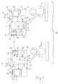
- the essential components of the control devices 10, 10 ' include, on the one hand, a position detection device 3, 3', for example a GPS receiver, which receives GPS signals from suitable position satellites PS.
- a position detection device 3, 3' for example a GPS receiver, which receives GPS signals from suitable position satellites PS.
- This is preferably a GPS receiver that is used in a corrected satellite-based system, for example with DGPS or the like. works to achieve the most accurate position determination possible - preferably to a few centimeters.
- control devices 10, 10 'each comprise a route planning data determination device 6, 6'.
- this route planning data determination device 6, 6 ' for example, any reference data, in particular reference lines, can be determined.
- z. B. by means of the position detecting means 3, the current position of the combine harvester 1, 2 are determined and it can be recorded with corresponding recording means along a traveled route each of the positions in order, as described above, reference lines or to generate reference points.
- information about the reference points can be input to an operator interface 9, 9 '.
- this user interface consists of a display unit 9, 9' in the form of a touch display with a central display area 9 D , on the various information can be displayed to the user, and arranged on the edge virtual buttons 9 T , These allow the operator to enter information to the system, such as additional information when creating reference data.
- the operator can hereby enter a start and an end point for recording a reference line.
- the respectively planned routes as well as various position data can also be output to the operator on the display unit 9.
- control devices 10, 10 ' Part of the control devices 10, 10 'is here also each a communication device 7, 7' with a transmitting unit 11, 11 'and a receiving unit 12, 12', so that the various control devices 10, 10 'of the combine 1, 2 can communicate with each other and in particular Exchange route planning data.
- control device 10, 10 'each comprise a route planning device 5, 5' and a coordination device 4, 4 '.
- the route planning data are respectively transferred to the route planning device 5, 5 ', which plans an optimal route on the basis of this data.
- the coordination device 4, 4 ' ensures a coordinated procedure, ie the machine systems 1, 2 or their route planning devices 5, 5' generate a common route plan which contains the optimized routes for the individual machine systems 1, 2.
- the route planning data also include within the route planning device 5, 5 'already planned partial routes, so that all route planning facilities 5, 5' are informed about the plans of the other machine systems and can take into account in the coordination of the route planning.
- the route planning data determination device 6, 6 ', the route planning device 5, 5' and the coordination device 4, 4 ' are preferably realized in the form of software modules on a central control processor 14, 14' of the respective control devices 10, 10 '.
- the control devices 10, 10 ' also each comprise a suitable memory device 13, 13'.
- suitable route planning data are stored, in particular generated reference data, which contain data about the territory to be processed such as impact limits, crop data, etc., but also the machine parameters of the respective agricultural machine system itself and those of the other machine systems in the group, insofar this is necessary.
- control devices 10, 10 ' also each comprise a travel control device 8, 8', d. H. a steering machine, which is controlled by the route planning device 5, 5 'so as to control the respective combine harvester 1, 2 exactly along the optimized routes provided for this combine harvester 1, 2.
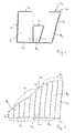
- FIG. 2 shows how, by a skilful recording of certain reference lines L 1 , L 2 , L 3 , L 4 , L 5 , L 6 , L 7 , L 8, separate areas, ie different ones, are shown
- Beds B 1 , B 2 , B 3 can be determined in a beat S 1 with polygonal outer edges.
- first the reference lines L 1 , L 4 , L 5 , L 6 , L 7 , L 8 can be traced, which define the outer edges of the impact S 1 .
- Further reference lines L 2 , L 3 can serve to subdivide the impact S 1 into three beds B 1 , B 2 , B 3 .
- These reference lines L 1 , L 2 , L 3 , L 4 , L 5 , L 6 , L 7 , L 8 can be determined by a first machine system, for example in the sowing of a tractor with appropriate sowing devices and then transmitted to other machine systems, the be used later in the process chain. Based on these reference lines, the following machine systems can plan their own optimal routes. In particular, in a parallel processing of this impact S 1, the individual beds B 1 , B 2 , B 3 can be assigned different machine systems of a machine grouping, which determine an optimum route for themselves on the basis of the reference lines for this bed B 1 , B 2 , B 3 with which the relevant machine system processes the bed B 1 , B 2 , B 3 .
- the individual machine systems may also preferably each a part of these reference lines L first , L 2 , L 3 , L 4 , L 5 , L 6 , L 7 , L 8 identify and exchange with each other to get as fast as possible all reference data for route planning.
- FIG. 1 An example of this is shown in FIG.
- a blow S 2 of two machine systems for example, two combine harvesters (not shown), at least partially processed in parallel.
- the first machine system moves along the upper edge of the cutting edge and cuts free the headland area at the upper edge of the field.
- the upper contour becomes of the beat S 2 recorded as the first reference line L 9 .
- the second machine system moves along the lower edge of the impact S 2 in FIG. 3 and cuts free the headland region there, the lower reference line L 11 being detected.
- Each of the combines then transmits the reference line L 9 , L 11 determined by it to the respective other combine harvester.
- the second combine harvester then moves on the right edge of the first track from bottom to top and records while another reference line L 12 .
- the first combine harvests the leftmost shorter track from top to bottom and thus detects the reference line L 10 .
- the route planning facilities can coordinate the optimum routes for the combine to plan.
- the blow S 2 is again divided into two beds B 4 , B 5 , since this is the optimal working strategy.
- the two combine harvesters then determine their sub-routes largely independently, but take into account and use the planning data of the other combine harvester.
- the first combine harvester can already plan and start its route after the bed has been laid out, while the second combine harvester is still driving off the longer right-hand edge.
- the already determined part of the reference line L 12 can always be transmitted up to date to the first combine harvester and included in the planning.
- the second combine first follows its route R 4 to approximately the middle region of the impact S 2 , along which the impact S 2 is to be subdivided into the two beds B 4 , B 5 . He then cuts free a middle track while also capturing another reference line L 13 .
- This reference line L 13 is then shifted to the right by one cutting width, so that a further reference line L v results, which is suitable as a virtual guideline for processing at the border of the two beds B 4 , B 5 for the second combine harvester.
- the second combine harvester can then make its route planning accordingly and proceed directly from the right marginal edge along the route R 2 to a lane corresponding to the derived reference line L v , then proceeding along the optimum route R 2 planned by it after processing this lane ,
- FIG. 4 shows a first variant for a possible use of the control method on a relatively large rectangular impact S 3 , which is processed with three combine harvesters 1, 2, 2 'operating in parallel in a work group.
- the combine harvester 1, 2, 2 'or their control devices can be constructed as shown in FIG. Since it is a rectangular field S 3 , it is sufficient if the first combine harvester 1 first leaves a first edge, in this case the left edge of the field S 3 , and the reference line L 14 is thereby generated. This combine harvester 1 then transmits the reference line L 14 to the further combine harvester 2, 2 'of the work association.
- the route planning can be carried out in such a way that there are no collisions or waiting times to avoid Collisions especially in the headland areas V can come.
- FIG. 5 again shows the same field S 3 , but here in the joint processing by the three machine systems with a different working strategy.
- the first reference line L 14 is first detected by driving the rightmost field edge through the first machine system.
- three machine systems with different working widths are to be used here. Therefore, the blow S 3 in skillful Way in beds B 6 , B 7 , B 8 divided, which is taken into account in the division, which bed B 6 , B 7 , B 8 is processed by which machine system with which working width.
- the bed sizes are chosen so that each machine system requires exactly four lanes F 6 , F 7 , F 8 for processing the respective bed B 6 , B 7 , B 8 . Due to the different track width correspondingly different bed widths result.
- the division of the impact S 3 in the various beds B 6 , B 7 , B 8 can be made for example by the first machine system, which also detects the reference line L 14 . For this, the working widths of the other machine systems must first be transferred to it.
- the route planning device of the first machine system then derives virtual reference lines L V6 , L V7 , L V8 from the originally recorded reference line L 14 for the individual beds B 6 , B 7 , B 8 , for example. These are transmitted together with the information about the bed width to the machine systems provided for the processing of the respective bed B 6 , B 7 , B 8 .
- the individual machine systems can then determine the additional lanes F 6 , F 7 , F 8 within the bed B 6 , B 7 , B 8 to be processed by them and set up an optimal route Considering the own machine parameters.
- the optimal routes are then returned to the first machine system, which operates as a "master machine system" and controls whether collisions can occur in the border areas between the beds B 6 , B 7 , B 8 . Ie. it is z. B. ensured that the routes are selected so that the working in the bed B 1 machine system only then the bordering on the bed B 2 last lane F 6 edited when the adjacent to the bed B 6 first lane F 7 of the second bed B 7 is already harvested.
- FIGS. 3 to 5 are only relatively small fields or sections of fields which are merely intended to reproduce basic possibilities for fieldwork. In reality, it will be much larger territories act with a variety of lanes, if for machining a bandage with several parallel machine systems to be used. Based on the examples, however, it is easy to grasp the advantages which the method according to the invention offers for coordinated route planning.
- FIG. 6 shows in more detail a display device 9, 9 'with a display surface 9 D and laterally arranged keys 9 T for operating a control device 10, 10' by a driver.
- a reference line L 15 for the definition of lanes F
- a reference line L 16 for the headland area
- the positions P H of detected obstacles such as straw bales, electricity pylons, trees or the like
- the own position P 1 of the vehicle and the position P 2 of another machine system can be displayed, which runs for example on a parallel lane.
- This is a "shared display", which is made available to all drivers of the machine systems involved, so that they each receive all information about their own machine system and the foreign machine systems.
- the driver can also select the type of presentation and, for example, switch from automatic driving operation to manual operation.
- the driver D is a virtual guidance and a symbol for the location of it serves engine system 1, 2 displayed on the display surface 9, so that the deviation of the symbol from the virtual guideline, which corresponds to the deviation of the engine system of the route to be driven, is displayed.
- the driver can manually control the vehicle relatively accurately along the desired route.
- certain safety zones can also be defined within the route planning and assigned to the various machine systems.
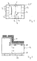
- An example is shown for this purpose in FIG. Shown there is a shock S 4 , which at the lower edge in the figure to a public transport area VB, here a road, adjacent. Through this road there is an increased safety risk by passing vehicles, ie it is in this area to pay particular attention that protrude when turning a machine system no machine parts in the traffic area VB.
- a safety zone SZ is defined for each machine system by means of a reference line L 18 running along the traffic area VB, which was recorded at the beginning of the work, which preferably depends on certain operating parameters, for example the turning radius and the working width of the machine system. The safety zone SZ is then assigned to the respective machine system.
- Another safety zone SZ ' is located at the upper impact edges of the impact S 4 in FIG.
- the impact S 4 adjoins a wooded area W.
- the reference line L 17 which runs along the upper edge of impact, defined a further safety zone SZ 'for the respective machine systems and assigned to the machine systems.
- FIGS. 8 and 9 show by way of example how a grid for driving lanes G 1 , G 2 , in particular spray lanes, can be created by means of reference lines, which can then be used for the control of tramline circuits or partial width circuits.
- different lanes F and tramlines G 1 , G 2 for example, for sowing on the relevant impact S 5 and set for subsequent work processes for the application of spraying and fertilizers.
- a reference line L 19 is first determined, which corresponds to the complete border of the shock S 5 .
- Lanes F are then calculated parallel to the right-hand edge of impact for the sowing, these lanes having a distance corresponding to the working width of the drill.
- a displaced reference line L G is determined along the left, bellied edge of impact, which serves to generate tramlines (injection molding) G 1 for the subsequent field sprayer.
- the distance between these spray lanes G 1 is selected according to the working width of the field sprayer.
- These spray lanes G 1 meet at different locations on the lanes F of the seeder. Consequently, the machine system can already take into account the planned spray lanes G 1 during sowing and automatically control them by means of the tramline circuit so that no seeding takes place in the area of the spray lanes G 1 .
- FIG. 9 shows an alternative in which the field S 5 is framed by a circumferential spray lane G 2 . This method is particularly suitable for smaller impacts S 5 for subsequent field sprayers and mineral fertilizer spreaders.
Abstract
Description
Die Erfindung betrifft ein Verfahren zur Erstellung eines Routenplans für eine Gruppe von landwirtschaftlichen Maschinensystemen für die Bearbeitung eines zu bearbeitenden Territoriums. Darüber hinaus betrifft die Erfindung ein Routenplanungssystem zur Erstellung eines entsprechenden Routenplans sowie ein Verfahren zur Steuerung einer Gruppe von landwirtschaftlichen Maschinensystemen bei der Bearbeitung eines zu bearbeitenden Territoriums, bei dem ein dementsprechend erstellter gemeinsamer Routenplan genutzt wird.The invention relates to a method for creating a route plan for a group of agricultural machine systems for processing a territory to be processed. Moreover, the invention relates to a route planning system for creating a corresponding route plan and to a method for controlling a group of agricultural machine systems when processing a territory to be processed, in which a correspondingly created common route plan is used.
Nachdem die Leistungsfähigkeit landwirtschaftlicher Maschinensysteme, d. h. von Arbeitsfahrzeugen wie z. B. Mähdreschern oder Feldhäckslern, Schleppern mit diversen Anbauten wie Düngerstreuern, Sämaschinen, Spritzgeräten, Wendern, Schwadern etc., immer weiter gesteigert wurde, gewinnt nun in den letzten Jahren die Planung des Arbeitsablaufs immer mehr an Bedeutung. Insbesondere bei der Ernte steht für die einzelnen Arbeitseinsätze wetterbedingt oft nur ein begrenzter Arbeitszeitraum zur Verfügung, der meist wegen einer mangelnden Einsatzplanung nicht optimal ausgenutzt wird. Darüber hinaus ist eine präzise Einsatzplanung wichtig, um die theoretisch mögliche maximale Leistungsfähigkeit der Maschinen auch im praktischen Einsatz zu erreichen. Um dieses Ziel einer optimalen Durchführung des Arbeitseinsatzes zu erreichen, wurden sog. Routenplanuhgssysteme und Routenplanungsverfahren entwickelt, mit denen für das jeweilige Maschinensystem eine optimale Route bei der Bearbeitung des betreffenden Territoriums, z. B. eines bestimmten Schlages, ermittelt wird. Das betreffende Maschinensystem kann dann je nach Ausgestaltung des Maschinensystems vollautomatisch, halbautomatisch oder einfach manuell entlang dieser Route verfahren werden. Üblicherweise arbeiten solche Routenplanungssysteme und Lenkautomaten mit satellitengestützten Navigationseinrichtungen, beispielsweise mit Hilfe von GPS-Empfängern (GPS = Global Positioning System). Zur Verbesserung der Genauigkeit gibt es verschiedene Korrekturverfahren, wie beispielsweise für ein GPS-Verfahren das sog. DGPS (Differentielles GPS).After the performance of agricultural machinery systems, ie of work vehicles such. As combine harvesters or forage harvesters, tractors with various attachments such as fertilizer spreaders, seeders, sprayers, reversers, rakes, etc., has been steadily increased, now in recent years, the planning of the workflow is becoming increasingly important. Especially during the harvest is due to the weather due to the weather often only a limited period of work available, which is usually not optimally utilized because of a lack of application planning. In addition, precise deployment planning is important in order to achieve the theoretically possible maximum performance of the machines in practical use. In order to achieve this goal of an optimal implementation of the labor input, so-called Routenplanuhgssysteme and route planning procedures have been developed with which for the respective machine system an optimal route in the processing of the territory concerned, z. B. a certain impact is determined. Depending on the configuration of the machine system, the relevant machine system can then be moved along this route fully automatically, semi-automatically or simply manually. Usually, such route planning systems and steering machines work with satellite-based navigation devices, for example with the aid of GPS receivers (GPS = Global Positioning System). To improve the accuracy, there are various correction methods, such as for a GPS method, the so-called DGPS (Differential GPS).
Ein Routenplanungssystem wird beispielsweise in der
In den meisten Fällen werden landwirtschaftliche Nutzflächen von mehreren Maschinensystemen bearbeitet. Das heißt, die Feldbearbeitung erfolgt durch eine ganze Gruppe von landwirtschaftlichen Maschinensystemen, welche innerhalb einer Prozesskette nacheinander aktiv sein können, wie dies beispielsweise bei einer Sämaschine und nachfolgenden Systemen zum Ausbringen von Spritz- und Düngemitteln der Fall ist, oder die parallel arbeiten können, wie beispielsweise mehrere Erntemaschinen, die in einem Arbeitsverband ein größeres Areal abernten. Grundsätzlich können diese verschiedenen Maschinensysteme - sofern sie über entsprechende Routenplanungs- und Automationssysteme verfügen - jeweils für sich eine ideale Route berechnen, die dann abgearbeitet wird.In most cases, agricultural land is processed by several machine systems. That is, the field processing is done by a whole group of agricultural machine systems, which can be active sequentially within a process chain, as is the case for example in a drill and subsequent systems for spreading spraying and fertilizers, or can work in parallel, such as For example, several harvesters that harvested in a labor association a larger area. Basically, these different machine systems - if they have the appropriate route planning and automation systems - each calculate an ideal route for itself, which is then processed.
Dies erfordert aber zunächst, dass jedes Maschinensystem wenigstens die Außenkontur des zu bearbeitenden Territoriums, beispielsweise durch einmaliges Umfahren, bestimmt. Ein solches Vorgehen ist relativ zeitaufwändig. Zwar besteht bereits die Möglichkeit, wie dies in der
Darüber hinaus treten Probleme auf, wenn mehrere Maschinen gleichzeitig auf einem, in der Regel größeren, Territorium arbeiten. Hier ist beim Abfahren der Routen durch die jeweiligen Fahrer besonders darauf zu achten, dass es nicht zu Kollisionen mit anderen Maschinensystemen kommt, weil sich beispielsweise Routen überschneiden. Ggf. kommt es auch zu unnötigen Wartezeiten, um eine Kollisionsgefahr zu vermeiden, oder zu Wartezeiten an Ressourcen, die von den Maschinensystemen gemeinsam genutzt werden, beispielsweise beim Einsatz mehrerer Mähdrescher, die ein gemeinsames Abtankfahrzeug nutzen müssen. Zudem ist bei größeren Territorien sowohl die Beschaffung der notwendigen Referenzlinien bzw. weiterer geographischer Routenplanungsdaten als auch die Erstellung eines kompletten Routenplans sehr zeitaufwendig.In addition, problems arise when several machines are working simultaneously on a, usually larger, territory. When driving down the routes by the respective driver, special care must be taken to ensure that there are no collisions with other machine systems because, for example, routes overlap. Possibly. There are also unnecessary waiting times to avoid a risk of collision or waiting times for resources that are shared by the machine systems, for example, when using several combine harvesters, which must use a common Abtankfahrzeug. In addition, the procurement of the necessary reference lines or further geographical route planning data as well as the creation of a complete route plan is very time-consuming for larger territories.
Es ist daher eine Aufgabe der vorliegenden Erfindung, ein verbessertes Verfahren zur Erstellung eines Routenplans für eine Gruppe von landwirtschaftlichen Maschinensystemen und ein entsprechendes Routenplanungssystem anzugeben, mit dem die o. g. Probleme vermieden werden.It is therefore an object of the present invention to provide an improved method for creating a route plan for a group of agricultural machine systems and a corresponding route planning system, with which the above-mentioned problems are avoided.
Diese Aufgabe wird zum einen durch ein Verfahren gemäß Patentanspruch 1 und zum anderen durch ein Routenplanungssystem gemäß Patentanspruch 12 gelöst.This object is achieved on the one hand by a method according to claim 1 and on the other hand by a route planning system according to
Bei dem erfindungsgemäßen Verfahren weisen die einzelnen landwirtschaftlichen Maschinensysteme jeweils eigene Routenplanungsdaten-Ermittlungseinrichtungen auf und stehen im Datenaustausch untereinander. Es wird dann auf Basis von ausgetauschten Routenplanungsdaten ein gemeinsamer Routenplan erstellt. Bei den ausgetauschten Routenplanungsdaten kann es sich um übliche Referenzdaten, beispielsweise Referenzlinien wie die Schlagbegrenzungen, Wegmarkierungen, Hindernisse etc. handeln. Es kann sich hierbei aber auch um bereits abgefahrene oder geplante, eigene (optimierte) Teilrouten, Einsatzdaten wie Art des Einsatzes und Feldfruchtdaten, d. h. Feldfruchteigenschaften und deren Auswirkungen für das jeweilige Maschinensystem, sowie um Maschinenparameter wie Arbeitsbreite, Wenderadius etc. handeln.In the method according to the invention, the individual agricultural machine systems each have their own route planning data determination devices and are in communication with each other. It is then created based on exchanged route planning data, a common route plan. The exchanged route planning data may be conventional reference data, such as reference lines such as beat limits, route markers, obstacles, etc. However, this may also involve already worn or planned, own (optimized) partial routes, operational data such as the type of use and crop data, ie. H. Crop characteristics and their effects for the respective machine system, as well as machine parameters such as working width, turning radius, etc. act.
Auf die erfindungsgemäße Weise kann sehr schnell und ökonomisch durch die Zusammenarbeit der Maschinensysteme ein Routenplan für das gesamte Territorium erstellt werden. Der gemeinsame Routenplan steht dann allen beteiligten Maschinensystemen und vorzugsweise auch anderen Maschinensystemen zur weiteren Verwendung zur Verfügung.In the manner of the invention can be created very quickly and economically by the cooperation of the machine systems, a route plan for the entire territory. The common route plan is then available to all involved machine systems and preferably also to other machine systems for further use.
Zum Aufbau eines erfindungsgemäßen Routenplanungssystems zur Durchführung des erfindungsgemäßen Verfahrens müssen die verschiedenen landwirtschaftlichen Maschinensysteme folgende Komponenten aufweisen:
- Positionsermittlungseinrichtungen, um eine aktuelle Position der betreffenden Maschinensysteme zu ermitteln;
- Routenplanungsdaten-Ermittlungseinrichtungen, um die notwendigen Routenplanungsdaten zur Verfügung zu stellen, beispielsweise durch automatische Erfassung der Positionsdaten sowie weiterer Zusatzinformationen und/oder durch Eingabe durch einen Bediener;
- Kommunikationseinrichtungen, um die Routenplanungsdaten zu versenden.
- Position determining means for determining a current position of the respective machine systems;
- Route planning data determining means for providing the necessary route planning data, for example by automatically acquiring the position data and other additional information and / or by input by an operator;
- Communication facilities to send the route planning data.
Außerdem wird zumindest eine Routenplanungseinrichtung benötigt, welche zum Empfang von Routenplanungsdaten mit einer Empfangseinheit gekoppelt ist, um auf Basis von empfangenen Routenplanungsdaten einen gemeinsamen Routenplan für das betreffende Territorium zu erstellen.In addition, at least one route planning device is required which is coupled to a receiving unit for receiving route planning data in order to create a common route plan for the relevant territory based on received route planning data.
Vorzugsweise weisen die einzelnen landwirtschaftlichen Maschinensysteme dabei jeweils eigene Routenplanungseinrichtungen auf und können die Routenplanungsdaten der anderen Maschinensysteme empfangen und verarbeiten. Der gemeinsame Routenplan kann dann koordiniert durch die Routenplanungseinrichtungen der Maschinensysteme auf Basis der ausgetauschten Routenplanungsdaten erstellt werden. Hierzu benötigen die landwirtschaftlichen Maschinensysteme jeweils eine mit der Routenplanungseinrichtung gekoppelte Koordinierungseinrichtung, welche so auf die Routenplanungseinrichtung einwirkt, dass koordiniert mit den Routenplanungseinrichtungen anderer Maschinensysteme innerhalb der Gruppe von Maschinensystemen auf Basis von ausgetauschten Routenplanungsdaten ein gemeinsamer Routenplan erstellt wird.Preferably, the individual agricultural machine systems each have their own route planning facilities and can receive and process the route planning data of the other machine systems. The common route plan can then be coordinated by the route planning facilities of the machine systems based on the exchanged route planning data. For this, the agricultural machine systems each require a coordination device coupled to the route planning device, which acts on the route planning device in such a way that a common route plan is created in coordination with the route planning devices of other machine systems within the group of machine systems on the basis of exchanged route planning data.
Grundsätzlich können die einzelnen Maschinensysteme aber auch alle ihre Routenplanungsdaten zunächst an eine zentrale Routenplanungseinrichtungen senden, die dann den gemeinsamen Routenplan erstellt. Bei der zentralen Routenplanungseinrichtung kann es sich bevorzugt auch um eine Routenplanungseinrichtung an einem der Maschinensysteme handeln, welche dann als eine Art "Master-Maschine" die Routenplanungsaufgabe übernimmt.In principle, however, the individual machine systems can also first send all their route planning data to a central route planning facility, which then creates the common route plan. The central route planning device can preferably also be a route planning device on one of the machine systems, which then undertakes the route planning task as a type of "master machine".
Das erfindungsgemäße Verfahren zur Erstellung eines gemeinsamen Routenplans wird vorzugsweise innerhalb eines Verfahrens zur Steuerung einer Gruppe von landwirtschaftlichen Maschinensystemen bei der Bearbeitung eines zu bearbeitenden Territoriums eingesetzt. Der gemeinsame Routenplan enthält dabei den einzelnen Maschinensystemen zugeordnete, optimierte Routen zur Bearbeitung des Territoriums. Das Verfahren der Maschinensysteme entlang der jeweiligen Route kann dann in bekannter Weise vollautomatisch, halbautomatisch oder manuell erfolgen, wie später noch näher erläutert wird.The method according to the invention for establishing a common route plan is preferably used within a method for controlling a group of agricultural machine systems when processing a territory to be processed. The common route plan Contains optimized routes for processing the territory assigned to the individual machine systems. The process of the machine systems along the respective route can then take place in a known manner fully automatically, semi-automatically or manually, as will be explained in more detail later.
Um ein solches Steuerungsverfahren durchführen zu können, sollten die Routenplanungseinrichtungen und die damit gekoppelten Koordinierungseinrichtungen der landwirtschaftlichen Maschinensysteme vorzugsweise so ausgebildet sein, dass der gemeinsame Routenplan den einzelnen Maschinensystemen zugeordnete optimierte Routen zur Bearbeitung des Territoriums enthält. Außerdem sollten die einzelnen Maschinensysteme dann bevorzugt neben den bereits oben genannten Komponenten jeweils eine Fahrsteuerungseinheit (Lenkautomat) und/oder eine Anzeigeeinheit zum Verfahren des Maschinensystems entlang einer Route aufweisen, je nachdem, ob die Steuerung vollautomatisch oder halbautomatisch bzw. manuell erfolgt.In order to be able to carry out such a control method, the route planning devices and the coordination devices of the agricultural machine systems coupled thereto should preferably be designed in such a way that the common route plan contains optimized routes for processing the territory assigned to the individual machine systems. In addition, the individual machine systems should then preferably each have a driving control unit (automatic steering) and / or a display unit for moving the machine system along a route, depending on whether the control is fully automatic or semi-automatic or manual.
Durch die Vernetzung der verschiedenen Routenplanungssysteme und den ständigen Datenaustausch ist es möglich, dass jeweils individuell für die einzelnen Maschinensysteme optimale Routen ermittelt werden, wobei bei der Optimierungsstrategie die Routen der jeweils anderen Fahrzeuge berücksichtigt werden. Das heißt, die Optimierung stellt nun nicht mehr isoliert auf ein einzelnes Fahrzeug ab, sondern es wird das gesamte Umfeld, insbesondere in vorherigen oder nachfolgenden Prozessschritten oder parallel dasselbe Territorium bearbeitende Maschinensysteme angemessen berücksichtigt. Es kann so der Gesamtarbeitsprozess optimiert werden. Kollisionsgefahren mit parallel arbeitenden Fahrzeugen oder unnötige Wartezeiten an gemeinsam genutzten Ressourcen und anderen Fahrzeugen können effektiv vermieden werden.By networking the various route planning systems and the constant exchange of data, it is possible that individual routes are determined individually for the individual machine systems, the routes of the respective other vehicles being taken into account in the optimization strategy. That is, the optimization is now no longer isolated from a single vehicle, but it is the entire environment, especially in previous or subsequent process steps or parallel in the same territory-processing machine systems are considered appropriate. It can thus be optimized the overall work process. Collision risks with parallel vehicles or unnecessary waiting times at shared resources and other vehicles can be effectively avoided.
Für die Kommunikation unter den Maschinensystemen können dabei beliebige bidirektionale Kommunikationssysteme und hierfür bekannte Sende/Empfangseinrichtungen, insbesondere funkgestützte Systeme, wie sie auch für Sprechfunk benutzt werden, zum Einsatz kommen. Beispielsweise ist aber auch die Nutzung von Mobilfunknetzen oder ähnlichem möglich.Any bidirectional communication systems and transmit / receive devices known therefor, in particular radio-based systems, as they may be, can thereby be used for communication among the machine systems used for voice transmission, are used. For example, the use of mobile networks or the like is possible.
Die abhängigen Ansprüche und die weitere Beschreibung enthalten besonders vorteilhafte Ausgestaltungen und Weiterbildungen der Erfindung, wobei die erfindungsgemäße Steuerungseinrichtung, das erfindungsgemäße landwirtschaftliche Maschinensystem und das erfindungsgemäße Steuersystem auch analog zu den abhängigen Verfahrensansprüchen weitergebildet sein können.The dependent claims and the further description contain particularly advantageous embodiments and developments of the invention, wherein the control device according to the invention, the agricultural machine system according to the invention and the control system according to the invention can also be developed analogously to the dependent method claims.
Wie bereits oben erläutert, umfassen die Routenplanungsdaten bevorzugt geographische Referenzdaten, wie beispielsweise verschiedene Referenzlinien, die die Schlagumrandungen angeben oder Positionen von Hindernissen etc.. Diese werden vorzugsweise mit Hilfe der Maschinensysteme selbst ermittelt.As already explained above, the route planning data preferably includes geographic reference data, such as different reference lines indicating the beat borders or positions of obstacles etc. These are preferably determined with the aid of the machine systems themselves.
Für das Aufzeichnen einer Referenzlinie gibt es verschiedene Möglichkeiten. Beispielsweise kann der Fahrer bei einer Variante beim Abfahren einer Referenzstrecke mittels einer Bedienerschnittstelle zunächst einen Startpunkt setzen und ebenso wieder einen Endpunkt setzen, wenn er das Ende der Referenzstrecke erreicht hat. Dabei ist es möglich, dass als Referenzstrecke einfach eine gerade Linie zwischen Start- und Endpunkt gezogen wird. Dies bietet sich beispielsweise an, wenn es sich um eine entsprechend gerade Schlagkante handelt oder um eine Linie im Schlag, entlang derer der Schlag in Teilgebiete unterteilt werden soll. Ebenso ist aber auch ein "Konturmodus" realisierbar, bei dem zwischen dem Startpunkt und dem Endpunkt der Referenzstrecke regelmäßig die Positionskoordinaten des Fahrzeugs erfasst und aufgezeichnet werden und somit die genaue Kontur der abgefahrenen Referenzstrecke erfasst wird und als Referenzlinie verwendet werden kann. Eine weitere Alternative besteht darin, dass nur ein Startpunkt vorgegeben wird und dann eine bestimmte Streckenlänge abgefahren wird.There are several ways to record a reference line. For example, in a variant when driving a reference route by means of an operator interface, the driver can first set a starting point and likewise set an end point again once he has reached the end of the reference route. It is possible that as a reference line simply draw a straight line between the start and end point. This is useful, for example, if it is a corresponding straight edge or a line in the field along which the beat is to be subdivided. Likewise, however, it is also possible to realize a "contour mode" in which the position coordinates of the vehicle are regularly recorded and recorded between the starting point and the end point of the reference path and thus the exact contour of the worn reference path is detected and can be used as a reference line. Another alternative is that only one starting point is specified and then a certain route length is traversed.
Bei einer Referenzlinie kann es sich, wie zuvor beschrieben, um eine einzelne Strecke handeln, beispielsweise nur einen Schlagrand. Eine Referenzlinie kann aber auch aus mehreren Teilstrecken zusammengesetzt sein, wobei die einzelnen Teilstrecken natürlich auch wieder als separate Referenzlinien angesehen werden können.As previously described, a reference line may be a single path, for example, just one punched edge. However, a reference line can also be composed of several sections, whereby the individual sections can, of course, again be regarded as separate reference lines.
Es ist grundsätzlich möglich, dass das erste Maschinensystem und das zweite Maschinensystem das Territorium zeitlich nacheinander bearbeiten, d. h. dass es sich um Maschinensysteme einer Verfahrenskette handelt, wie z. B. eine Sämaschine und eine Feldspritze oder eine Schneidemaschine und nachfolgende Wender und Schwader. Vorzugsweise wird das Verfahren jedoch auch dann genutzt, wenn das erste Maschinensystem und das zweite Maschinensystem ein Territorium zumindest zeitweise parallel bearbeiten, wie z. B. für die Maschinen eines Maschinenverbands, welche parallel ein größeres Gebiet abarbeiten. Dabei können die einzelnen Maschinensysteme auch gleichartige Maschinensysteme, beispielsweise mehrere Mähdrescher oder mehrere Feldhäcksler - auch desselben Typs - sein.In principle, it is possible for the first machine system and the second machine system to process the territory one after the other, ie. H. that it is machine systems of a process chain, such. As a seeder and a field sprayer or a cutting machine and subsequent turner and swather. Preferably, however, the method is also used when the first machine system and the second machine system at least temporarily edit a territory in parallel, such. B. for the machines of a machine shop, which work in parallel a larger area. The individual machine systems can also be similar machine systems, for example a plurality of combine harvesters or a plurality of forage harvesters of the same type.
Insbesondere, wenn mehrere Maschinen gleichzeitig oder nur teilweise zeitlich versetzt ein Territorium gemeinsam bearbeiten, sollte die Übergabe aller Informationen, vor allem der Referenzlinien, dynamisch während des gesamten Arbeitseinsatzes erfolgen, d. h. sobald eines der Maschinensysteme neue Referenzdaten ermittelt, werden diese sofort an die anderen Maschinensysteme übersendet. Dabei kann eine Übersendung durch das Maschinensystem automatisch erfolgen und/oder durch den Bediener des jeweiligen Maschinensystems veranlasst werden. Ebenso ist es aber auch möglich, eine Übersendung bzw. einen Empfang neuer Referenzdaten zu unterbinden bzw. zu verzögern.In particular, if several machines work on a territory simultaneously or only partially offset in time, the transfer of all information, especially the reference lines, dynamically throughout the work should be done, d. H. As soon as one of the machine systems determines new reference data, it is immediately sent to the other machine systems. In this case, a transmission can be carried out automatically by the machine system and / or be initiated by the operator of the respective machine system. Likewise, it is also possible to prevent or delay a transmission or reception of new reference data.
Mit dem erfindungsgemäßen Verfahren ist es vorteilhafterweise auch möglich, dass die Maschinensysteme insbesondere beim Start eines parallelen Einsatzes jeweils einen Teil der benötigten Referenzstrecken abfahren und sich diese gegenseitig übersenden, um so alle erforderlichen Referenzdaten möglichst schnell zu gewinnen. Beispielsweise könnte ein Maschinensystem den rechten und den oberen Schlagrand abfahren, während gleichzeitig ein anderes Maschinensystem den linken und den unteren Schlagrand abfährt.With the method according to the invention, it is advantageously also possible for the machine systems, in particular when starting a parallel insert, to each run off a part of the required reference paths and to transmit them to one another in order to obtain all required reference data win as fast as possible. For example, one machine system could drive off the right and upper beating edges while at the same time another machine system is pulling off the left and lower beating edges.
Das durch die Referenzdaten spezifizierte, zu bearbeitende Territorium kann dann beispielsweise auf Basis der Routenplanungsdaten auch in Teilgebiete unterteilt werden. Dies bietet sich insbesondere bei einer gleichzeitigen Abarbeitung durch mehrere Maschinensysteme in einem Maschinenverband an oder wenn es sich um ein Schlagstück mit sehr unregelmäßiger Form handelt.The territory to be processed specified by the reference data can then also be subdivided into subareas based, for example, on the route planning data. This is particularly suitable for a simultaneous execution by several machine systems in a machine group or if it is a hammer with very irregular shape.
Es kann dann beispielsweise von den verschiedenen Maschinensystemen jeweils auch ein separater Teilroutenplan für ein bestimmtes Teilgebiet des zu bearbeitenden Territoriums ermittelt werden. Dies hat den Vorteil, dass jede der Routenplanungseinrichtungen in "ihrem" Teilgebiet relativ frei die optimale Route für das betreffende Maschinensystem optimieren kann, ohne andere Maschinensysteme zu berücksichtigen. Eine genauere Koordinierung der Streckenplanung ist dann im Wesentlichen nur noch in den Fahrspuren, an denen die Teilgebiete aneinander angrenzen, sowie in gemeinsam genutzten Vorgewendebereichen bzw. auf Strecken von und zu gemeinsam genutzten Ressourcen erforderlich.It is then possible, for example, to determine from the various machine systems in each case a separate partial route plan for a specific subarea of the territory to be processed. This has the advantage that each of the route planning facilities in "their" subarea can relatively freely optimize the optimal route for the particular machine system without taking into account other machine systems. A more precise coordination of the route planning is then essentially only in the lanes where the subareas adjoin one another, as well as in shared headland areas or on routes to and from shared resources required.
Besonders bevorzugt werden wiederholt, d. h. kontinuierlich oder in zeitlichen Abständen, aktuelle geographische Positionsdaten der einzelnen Maschinensysteme ermittelt, die an die jeweils anderen Maschinensysteme übersandt werden. Dies ist insbesondere dann vorteilhaft, wenn mehrere Maschinen parallel auf einem Schlag arbeiten. Alle Maschinensysteme wissen dann jeweils, wo sie sich befinden und wo sich die jeweils anderen Maschinensysteme befinden. Es können so beispielsweise durch Vorgaben von Sicherheitsabständen und Notabschaltungen, wenn der Sicherheitsabstand überschritten wird, Kollisionen sicher vermieden werden.Particularly preferably, current or geographical position data of the individual machine systems, which are transmitted to the respective other machine systems, are determined repeatedly, ie continuously or at intervals. This is particularly advantageous when several machines work in parallel in one go. All machine systems then know where they are and where the other machine systems are located. For example, by specifying safety distances and emergency shutdowns, if the safety distance is exceeded, collisions can be safely avoided.
Bei einer besonders bevorzugten Weiterbildung des Verfahrens wird dynamisch der Routenplan geändert, wenn ein neues Maschinensystem zur Gruppe hinzukommt oder wenn ein Maschinensystem die Gruppe verlässt. Dies bietet die Möglichkeit, dass jederzeit neue Maschinensysteme in die Gruppe aufgenommen werden können bzw. Maschinensysteme die Arbeitsgruppe verlassen können, weil z. B. ein Defekt vorliegt oder sie an anderer Stelle gebraucht werden. Wenn ein neues Maschinensystem hinzukommt, muss dieses lediglich mit den anderen Maschinensystemen in Kommunikationsverbindung treten und sich innerhalb der Gruppe "anmelden", indem es seine bereits vorhandenen Routenplanungsdaten übersendet, wobei es sich im einfachsten Fall um die eigenen Positionsdaten, die eigenen Maschinenparameter sowie Informationen darüber handelt, dass dieses Maschinensystem sich an dem betreffenden Arbeitseinsatz beteiligen soll. Es erhält dann von den anderen Maschinensystemen deren Routenplanungsdaten, wozu auch der bereits bestehende Routenplan gehört. Die Maschinensysteme können dann koordiniert den gemeinsamen Routenplan ändern, um das hinzukommende Maschinensystem optimal einzubinden. In ähnlicher Weise kann der Routenplan geändert werden, wenn sich ein Maschinensystem bei der Gruppe "abmeldet".In a particularly preferred embodiment of the method, the route plan is dynamically changed when a new machine system is added to the group or when a machine system leaves the group. This offers the possibility that new machine systems can be added to the group at any time or that machine systems can leave the working group because, for example, B. a defect is present or they are needed elsewhere. When a new machine system is added, it simply has to communicate with the other machine systems and "log in" within the group by sending its already existing route planning data, in the simplest case its own position data, its own machine parameters and information about it is that this machine system should participate in the work in question. It then receives from the other machine systems their route planning data, including the already existing route plan belongs. The machine systems can then coordinate to change the common route plan to optimally integrate the added machine system. Similarly, the route plan can be changed when a machine system "logs out" to the group.
Besonders bevorzugt werden für die Bediener der Maschinensysteme mittels einer geeigneten Anzeigeeinrichtung jeweils eine auf Basis der ausgetauschten geographischen Referenzdaten erstellte gemeinsame Karte, die aktuelle Position und die optimale Route des betreffenden Maschinensystems sowie die aktuellen Positionen der sich gerade auf dem zu bearbeitenden Territorium befindenden anderen Maschinensysteme der Gruppe ausgegeben. Auf diese Weise haben alle Bediener während des Arbeitseinsatzes immer den kompletten Überblick über das aktuelle Geschehen. Besonders bevorzugt werden den Bedienern dabei nicht nur die eigene Route, sondern auch die Routen der anderen sich jeweils auf dem zu bearbeitenden Territorium befindenden Maschinensysteme der Gruppe angezeigt. Es kann so noch einmal durch die Bediener überprüft werden, ob die Routen auch nach ihrer Einschätzung optimal verlaufen oder ob an bestimmten Stellen evtl. durch fehlerhafte Planungen Kollisionsgefahr oder unnötige Wartezeiten entstehen könnten. Neben den Routen und Positionen können auch Zusatzinformationen wie Wegmarkierungen, bereits bearbeitete Fahrspuren, Hindernisse, Sperrflächen etc. angezeigt werden.Particularly preferred for the operators of the machine systems by means of a suitable display device in each case based on the exchanged geographical reference data created common map, the current position and the optimal route of the relevant machine system and the current positions of the currently located on the territory to be processed other machine systems Group spent. In this way, all operators have the complete overview of the current events during the work. It is particularly preferable for the operators not only to display their own route, but also the routes of the other machine systems of the group that are in each case located on the territory to be processed. It can thus be checked again by the operator, whether the routes are also optimal in their estimation or at certain points possibly through Incorrect planning could result in collision or unnecessary waiting times. In addition to the routes and positions, additional information such as route markings, already edited lanes, obstacles, restricted areas, etc. can also be displayed.
Grundsätzlich können die verschiedenen Maschinensysteme mit unterschiedlichen Koordinatensystemen arbeiten und es werden dann jeweils die übermittelten Koordinaten umgerechnet. Bei einer bevorzugten Variante arbeiten jedoch alle Maschinensysteme mit demselben Koordinatensystem mit einem genau definierten Ursprung. Es wird dabei vorzugsweise ein lokales Koordinatensystem verwendet, dessen Ursprung- beispielsweise eine Ecke des zu bearbeitenden Territoriums - in Form von Koordinaten des satellitenunterstützten Navigationssystems definiert ist, z. B. als GPS-Position mit Breitengrad, Längengrad und Elevation. Dieser "Nullpunkt" ist dann für alle Maschinensysteme identisch.Basically, the various machine systems can work with different coordinate systems and then the transmitted coordinates are then converted. In a preferred variant, however, all machine systems work with the same coordinate system with a well-defined origin. A local coordinate system is preferably used, the origin of which-for example, a corner of the territory to be processed-is defined in the form of coordinates of the satellite-supported navigation system, eg. B. as a GPS position with latitude, longitude and elevation. This "zero point" is then identical for all machine systems.
Wie bereits oben kurz erläutert, können die Maschinensysteme vollautomatisch entlang der optimierten Routen gesteuert werden, sofern die Maschinensysteme mit entsprechenden Fahrsteuerungseinheiten, d. h. Lenkautomaten, ausgestattet sind. In einem solchen Fall ist es aus sicherheitstechnischen Gründen aber immer möglich, das System durch den Bediener übersteuern zu lassen, d. h. sobald dieser bestimmte Steuerungsorgane wie Bremse, Lenkrad, Kupplung etc. betätigt, wird der Lenkautomat ausgeschaltet. Ebenso ist aber auch eine halbautomatische Steuerung bzw. eine manuelle Steuerung möglich, bei der dem Fahrer auf einer Anzeigeeinrichtung seine Route, d. h. eine bestimmte einzuhaltende Fahrspur sowie seine aktuelle Position und ggf. weitere Hilfsanzeigen wie Winkelabweichung etc. angezeigt werden, mit Hilfe derer der Fahrer manuell das Fahrzeug auf der vorgegebenen Fahrspur halten kann.As already briefly explained above, the machine systems can be controlled fully automatically along the optimized routes, provided that the machine systems with corresponding driving control units, i. H. Steering machines are equipped. In such a case, however, it is always possible, for safety reasons, to override the system by the operator, i. H. as soon as this certain control elements such as brake, steering wheel, clutch, etc. operated, the steering control is turned off. Likewise, however, a semi-automatic control or manual control is possible in which the driver on a display device his route, d. H. a certain lane to be kept and its current position and possibly other auxiliary displays such as angular deviation, etc. are displayed, with the help of which the driver can manually hold the vehicle on the predetermined lane.
Vorzugsweise können auf Basis der Routenplanungsdaten der verschiedenen Maschinensysteme auch Sicherheitszonen definiert werden, welche den verschiedenen Maschinensystemen zugeordnet sind. In diesen Sicherheitszonen kann die automatische Steuerung der jeweils zugeordneten Maschinensysteme eingeschränkt, insbesondere auch vollständig deaktiviert werden. Typische Sicherheitszonen sind Bereiche in Straßennähe oder Bereiche in Gebieten, in denen beispielsweise aufgrund von benachbarter dichter Bewaldung o. Ä. Positionssignale nur ungenau empfangen werden können.Preferably, based on the route planning data of the various machine systems, security zones can also be defined which are assigned to the various machine systems. In these security zones the automatic control of the respective associated machine systems can be restricted, in particular completely deactivated. Typical security zones are areas near the road or areas in areas where, for example, due to adjacent dense forestry or the like. Position signals can only be received inaccurate.
Bei einer bevorzugten Variante der Erfindung wird zunächst auf Basis einer ursprünglich ermittelten Referenzlinie eine abgeleitete Referenzlinie ermittelt. Beispielsweise können aus ursprünglich aufgenommenen Referenzlinien, welche den Schlagkanten entsprechen, verschobene Referenzlinien als virtuelle Leitlinien erzeugt werden, welche die Fahrspuren für die einzelnen Maschinensysteme definieren. Dabei kann bevorzugt ein fester Versatz zwischen den abgeleiteten Referenzlinien vorgesehen sein. Hierzu ist lediglich erforderlich, dass bekannt ist, welche Arbeitsbreite die Maschinen haben, die die Referenzlinien nutzen sollen. Dies ist vor allem dann sinnvoll, wenn mehrere Maschinensysteme parallel ein und dasselbe Feld bearbeiten.In a preferred variant of the invention, a derived reference line is first determined on the basis of an originally determined reference line. For example, reference lines shifted from originally recorded reference lines which correspond to the impact edges can be generated as virtual guidelines which define the lanes for the individual machine systems. In this case, a fixed offset between the derived reference lines can preferably be provided. For this it is only necessary that it is known what working width the machines have to use the reference lines. This is especially useful if several machine systems are processing one and the same field in parallel.
Darüber hinaus können die abgeleiteten Referenzlinien auch zur Spezifizierung von Fahrgassen für spätere Maschinensysteme in einer Prozesskette definiert werden. So können beispielsweise vorzugsweise bei einem Einsatz eines Maschinensystems zur Einsaat so genannte "Spritzengassen" erstellt werden, und es werden gleichzeitig passende Referenzlinien für diese Spritzengassen generiert, die dann einer später nachfolgenden Feldspritze zur Verfügung gestellt werden.In addition, the derived reference lines can also be defined to specify tramlines for future machine systems in a process chain. Thus, for example, so-called "spray lanes" can preferably be created when using a machine system for sowing, and matching reference lines for these spray lanes are generated at the same time, which are then made available to a later-following field sprayer.
Durch die Nutzung solcher abgeleiteten Referenzlinien zur Spezifizierung von Fahrgassen ist es insbesondere auch möglich, dass verschiedene Arbeitseinsätze innerhalb einer Prozesskette dahingehend optimiert werden, dass die jeweiligen Maschinensysteme nicht exakt die gleichen Fahrspuren benutzen, um so eine übermäßige Verdichtung des Bodens entlang der Fahrspuren zu vermeiden.By using such derived reference lines for specifying tramlines, it is also possible, in particular, for different work assignments within a process chain to be optimized such that the respective machine systems do not use exactly the same lanes so as to avoid excessive compaction of the floor along the lanes.
Bei einer bereits oben erwähnten bevorzugten Variante arbeitet eine bestimmte Arbeitsmaschine als "Master-Maschine" und die anderen Maschinensysteme jeweils als "Client-Maschinen". Dies kann besonders bevorzugt auch jederzeit durch die Bediener der Maschinensysteme oder einen Bediener mit spezieller Autorisierung hierzu festgelegt werden. In einem solchen Fall erfolgen die Koordination und Routenplanung dann vorzugsweise durch das Routenplanungssystem der "Master-Maschine". Diese "Master-Maschine" erhält z. B. die Routenplanungsdaten der "Client-Maschinen" und vergibt ihrerseits bei der Routenplanung Teilaufträge an die einzelnen "Client-Maschinen", um die Rechenkapazitäten optimal auszunutzen. Beispielsweise könnte diese "Master-Maschine" auf Basis der von den einzelnen Maschinensystemen erhaltenen Routenplanungsdaten, d. h. insbesondere deren Positionsdaten, deren Maschinenparameter und der ermittelten Referenzdaten, den zu bearbeitenden Schlag in Teilgebiete (Beete) aufteilen und den verschiedenen "Client-Maschinen" zuweisen. Die Aufteilung des Schlages in Beete und die Zuweisung zu den einzelnen "Client-Maschinen" kann dabei unter Berücksichtigung der Maschinenparameter insoweit erfolgen, dass beispielsweise einer leistungsfähigeren Maschine mit größerer Arbeitsbreite ein größeres Beet zugewiesen wird und einer Maschine mit kleinerer Arbeitsleistung und kleinerer Arbeitsbreite ein entsprechend kleineres Beet. Die einzelnen "Client-Maschinen" können dann ihre Routen innerhalb der Beete selbständig planen und die geplanten Routen an die "Master-Maschine" zurücksenden. In der dortigen Routenplanungseinrichtung und/oder Koordinationseinrichtung wird dann überprüft, inwieweit die einzelnen Routen koordiniert verlaufen oder ob es zu problematischen Überschneidungen kommt. Insbesondere kann die "Master-Maschine" auch Rahmenbedingungen für die Planung der Routen in den Beeten durch die "Client-Maschinen" vorgeben, um bereits so eine optimale Koordinierung sicherzustellen und Kollisionen und Wartezeiten zu vermeiden.In a preferred variant already mentioned above, one particular work machine operates as a "master machine" and the other machine systems each as a "client machine". This can particularly preferably also be defined at any time by the operators of the machine systems or an operator with special authorization for this purpose. In such a case, the coordination and route planning are then preferably carried out by the route planning system of the "master machine". This "master machine" receives z. B. the route planning data of the "client machines" and in turn awards in the route planning partial orders to the individual "client machines" in order to make optimum use of the computing capacity. For example, this "master machine" could be based on the route planning data received from the individual machine systems, i. H. in particular, their position data, their machine parameters and the determined reference data, divide the impact to be processed into subregions (beds) and assign them to the various "client machines". The division of the impact into beds and the assignment to the individual "client machines" can take place taking into account the machine parameters to the extent that, for example, a more powerful machine with a larger working width a larger bed is assigned and a machine with smaller work and smaller working width accordingly smaller bed. The individual "client machines" can then plan their routes within the beds independently and send the planned routes back to the "master machine". In the local route planning device and / or coordination device is then checked to what extent the individual routes are coordinated or whether there are problematic overlaps. In particular, the "master machine" can also specify framework conditions for the planning of the routes in the flower beds by the "client machines" in order to ensure optimal coordination and avoid collisions and waiting times.
Die Erfindung wird im Folgenden unter Hinweis auf die beigefügten Figuren anhand von Ausführungsbeispielen noch einmal näher erläutert. Hieraus ergeben sich auch weitere Einzelheiten und Vorteile der Erfindung. Es zeigen:
- Figur 1 eine schematische Darstellung zweier Maschinensysteme mit erfindungsgemäßen Steuerungseinrichtungen,
- Figur 2 eine Darstellung möglicher Referenzlinien bei einem Territorium mit polygonen Außenkonturen,
Figur 3 ein in Fahrstrecken unterteiltes, von zwei Arbeitsmaschinen abzuarbeitendes Territorium,Figur 4 ein Territorium, welches von einem Arbeitsverband mit drei Maschinensystemen nach einem Routenplan gemäß einem ersten Ausführungsbeispiel abzuarbeiten ist,- Figur 5 das
Territorium gemäß Figur 4, welches von einem Arbeitsverband mit drei Maschinensystemen nach einem Routenplan gemäß einem zweiten Ausführungsbeispiel abzuarbeiten ist, - Figur 6 eine Darstellung einer Anzeigeeinrichtung 9 mit einer darauf angezeigten Feldkarte,
- Figur 7 ein Territorium mit eingezeichneten Sicherheitsbereichen,
- Figur 8 ein Territorium mit auf Basis von Referenzlinien erstellten Fahrspuren bei der Einsaat und zusätzlich definierten Spritzengassen gemäß einem ersten Ausführungsbeispiel,
Figur 9 ein Territorium mit auf Basis von Referenzlinien erstellten Fahrspuren bei der Einsaat und zusätzlich definierten Spritzengassen gemäß einem zweiten Ausführungsbeispiel.
- FIG. 1 shows a schematic representation of two machine systems with control devices according to the invention,
- FIG. 2 shows a representation of possible reference lines in the case of a territory with polygonal outer contours,
- 3 shows a subdivided into routes, to be processed by two machines, territory
- FIG. 4 shows a territory which is to be processed by a work organization with three machine systems according to a route plan according to a first exemplary embodiment,
- FIG. 5 shows the territory according to FIG. 4, which is to be processed by a work organization with three machine systems according to a route plan according to a second exemplary embodiment,
- 6 shows an illustration of a
display device 9 with a field map displayed thereon, FIG. - FIG. 7 shows a territory with marked security areas,
- FIG. 8 shows a territory with lanes created on the basis of reference lines during sowing and additionally defined spray lanes according to a first exemplary embodiment,
- FIG. 9 a territory with lanes created on the basis of reference lines during sowing and additionally defined injection lanes according to a second exemplary embodiment.
Bei dem in Figur 1 dargestellten Ausführungsbeispiel des erfindungsgemäßen Steuerungssystems werden der Einfachheit halber nur zwei gleichartig aufgebaute Maschinensysteme 1, 2, hier zwei Mähdrescher 1, 2, dargestellt, die z. B. gemeinsam in einer Gruppe G (d.h. einem Maschinenverband) eingesetzt werden können, um ein größeres Areal in möglichst kurzer Zeit abzuarbeiten.In the embodiment of the control system according to the invention shown in Figure 1, for simplicity, only two identically constructed machine systems 1, 2, here two combine 1, 2, shown, for. B. together in a group G (i.e., a machine group) can be used to work off a larger area in the shortest possible time.
Der Aufbau und die Funktionsweise solcher Mähdrescher 1, 2 sind dem Fachmann ebenso wie geeignete Steuerungssysteme zur Steuerung der Mähdrescher 1, 2 grundsätzlich bekannt. Des Weiteren sind beispielsweise aus der
Zu den wesentlichen Komponenten der Steuerungseinrichtungen 10, 10' (die für beide Maschinensysteme ebenfalls identisch aufgebaut sind) zählen hier zum einen jeweils eine Positionsermittlungseinrichtung 3, 3', beispielsweise ein GPS-Empfänger, welcher GPS-Signale von geeigneten Positionssatelliten PS erhält. Vorzugsweise handelt es sich hierbei um einen GPS-Empfänger, der in einem korrigierten satellitengestützten System, beispielsweise mit DGPS o. Ä. arbeitet, um eine möglichst exakte Positionsbestimmung - bevorzugt auf wenige Zentimeter genau - durchzuführen.The essential components of the
Die Steuerungseinrichtungen 10, 10' umfassen darüber hinaus jeweils eine Routenplanungsdaten-Ermittlungseinrichtung 6, 6'. Mit dieser Routenplanungsdaten-Ermittlungseinrichtung 6, 6' können beispielsweise beliebige Referenzdaten, insbesondere Referenzlinien, ermittelt werden. Hierzu kann z. B. mittels der Positionsermittlungseinrichtung 3 die aktuelle Position des Mähdreschers 1, 2 ermittelt werden und es können mit entsprechenden Aufzeichnungsmitteln entlang einer abgefahrenen Strecke jeweils die Positionen aufgezeichnet werden, um daraus, wie bereits oben beschrieben, Referenzlinien oder auch Referenzpunkte zu generieren. Zusätzlich können Informationen zu den Referenzpunkten an einer Bedienerschnittstelle 9, 9' eingegeben werden. Bei der dargestellten Steuerungseinrichtung 10, 10' besteht diese Bedienerschnittstelle aus einer Anzeigeeinheit 9, 9' in Form eines Touch-Displays mit einer mittleren Displayfläche 9D, auf der verschiedene Informationen für den Benutzer angezeigt werden können, sowie am Rand angeordneter virtueller Tasten 9T. Über diese kann der Bediener Informationen an das System eingeben, beispielsweise Zusatzinformationen bei der Erstellung von Referenzdaten. Insbesondere kann der Bediener hiermit einen Start- und einen Endpunkt zur Aufzeichnung einer Referenzlinie eingeben. Auf der Anzeigeeinheit 9 können auch, wie später noch näher erläutert wird, die jeweils geplanten Routen sowie verschiedene Positionsdaten an den Bediener ausgegeben werden.In addition, the
Teil der Steuerungseinrichtungen 10, 10' ist hier auch jeweils eine Kommunikationseinrichtung 7, 7' mit einer Sendeeinheit 11, 11' und einer Empfangseinheit 12, 12', damit die verschiedenen Steuerungseinrichtungen 10, 10' der Mähdrescher 1, 2 miteinander kommunizieren können und insbesondere Routenplanungsdaten austauschen können.Part of the
Des Weiteren umfassen die Steuerungseinrichtung 10, 10' jeweils eine Routenplanungseinrichtung 5, 5' und eine Koordinierungseinrichtung 4, 4'.Furthermore, the
Die Routenplanungsdaten werden jeweils an die Routenplanungseinrichtung 5, 5' übergeben, welche aufgrund dieser Daten eine optimale Route plant. Erfindungsgemäß können dabei die Routenplanungsdaten aller Maschinensysteme 1, 2 innerhalb der Gruppe G herangezogen werden, da diese ja über die Kommunikationseinrichtung 7 ausgetauscht werden. Hierbei sorgt erfindungsgemäß die Koordinierungseinrichtung 4, 4' für ein koordiniertes Vorgehen, d. h. die Maschinensysteme 1, 2 bzw. deren Routenplanungseinrichtungen 5, 5' generieren einen gemeinsamen Routenplan, welcher die optimierten Routen für die einzelnen Maschinensysteme 1, 2 enthält. Dabei wird an dieser Stelle noch einmal darauf hingewiesen, dass die Routenplanungsdaten auch innerhalb der Routenplanungseinrichtung 5, 5' bereits geplante Teilrouten umfassen, damit alle Routenplanungseinrichtungen 5, 5' über die Planungen der anderen Maschinensysteme informiert sind und diese bei der Koordinierung der Routenplanung berücksichtigen können.The route planning data are respectively transferred to the route planning device 5, 5 ', which plans an optimal route on the basis of this data. According to the route planning data of all machine systems 1, 2 within the group G can be used, since they are exchanged via the communication device 7 yes. According to the invention, the
Die Routenplanungsdaten-Ermittlungseinrichtung 6, 6', die Routenplanungseinrichtung 5, 5' sowie die Koordinierungseinrichtung 4, 4' sind vorzugsweise in Form von Softwaremodulen auf einem zentralen Steuerungsprozessor 14, 14' der jeweiligen Steuerungseinrichtungen 10, 10' realisiert.The route planning data determination device 6, 6 ', the route planning device 5, 5' and the
Die Steuerungseinrichtungen 10, 10' umfassen außerdem jeweils eine geeignete Speichereinrichtung 13, 13'. In dieser werden bzw. sind unter anderem geeignete Routenplanungsdaten hinterlegt, insbesondere generierte Referenzdaten, welche Daten über das abzuarbeitende Territorium wie Schlaggrenzen, Feldfruchtdaten etc. enthalten, aber auch die Maschinenparameter des jeweiligen landwirtschaftlichen Maschinensystems selbst sowie die der anderen in der Gruppe befindlichen Maschinensysteme, soweit dies notwendig ist.The
Bei dem in Figur 1 gezeigten Ausführungsbeispiel umfassen die Steuerungseinrichtungen 10, 10' auch jeweils eine Fahrsteuerungseinrichtung 8, 8', d. h. einen Lenkautomaten, der von der Routenplanungseinrichtung 5, 5' angesteuert wird, um so den jeweiligen Mähdrescher 1, 2 exakt entlang der für diesen Mähdrescher 1, 2 vorgesehenen optimierten Routen zu steuern.In the exemplary embodiment shown in FIG. 1, the
Anhand der nachfolgenden Figuren 2 bis 5 werden verschiedene Beispiele erläutert, wie mit Hilfe der erfindungsgemäßen vernetzten bzw. koordinierten Routenplanungseinrichtungen 5, 5' der verschiedenen Maschinensysteme 1, 2 innerhalb einer Gruppe G in verschiedensten Situationen eine optimierte Routenplanung durchgeführt werden kann.Various examples will be explained with reference to the following FIGS. 2 to 5 of how, with the help of the networked or coordinated route planning devices 5, 5 'of the various machine systems 1, 2 within a group G, optimized route planning can be carried out in a wide variety of situations.
Figur 2 zeigt, wie durch eine geschickte Aufnahme bestimmter Referenzlinien L1, L2, L3, L4, L5, L6, L7, L8 gesonderte Flächenbereiche, d.h. verschiedene Beete B1, B2, B3 in einem Schlag S1 mit polygonen Außenkanten bestimmt werden können. So können beispielsweise zunächst die Referenzlinien L1, L4, L5, L6, L7, L8 abgefahren werden, die die Außenkanten des Schlages S1 definieren. Weitere Referenzlinien L2, L3, können dazu dienen um den Schlag S1 in drei Beete B1, B2, B3 zu unterteilen. Diese Referenzlinien L1, L2, L3, L4, L5, L6, L7, L8 können von einem ersten Maschinensystem beispielsweise bei der Einsaat von einem Schlepper mit entsprechender Säheinrichtungen ermittelt und dann an weitere Maschinensysteme übermittelt werden, die später in der Prozesskette verwendet werden. Anhand dieser Referenzlinien können die nachfolgenden Maschinensysteme ihre eigenen optimalen Routen planen. Insbesondere können bei einer parallelen Bearbeitung dieses Schlages S1 den einzelnen Beeten B1, B2, B3 verschiedene Maschinensysteme eines Maschinenverbandes zugeordnet werden, welche für sich anhand der für dieses Beet B1, B2, B3 geltenden Referenzlinien eine optimale Route ermitteln, mit der das betreffende Maschinensystem das Beet B1, B2, B3 bearbeitet. Dabei sollte insbesondere in den Grenzgebieten und Vorgewendebereichen auf einen koordinierten Ablauf bei der Routenplanung geachtet werden, d.h. es wird vorzugsweise ein Gesamt-Routenplan erstellt, in den die jeweiligen Routen für die einzelnen Beete B1, B2, B3 so integriert sind, dass eine Optimierung hinsichtlich des kompletten Arbeitseinsatzes (und nicht nur hinsichtlich der einzelnen Beete B1, B2, B3) erfolgt. Sofern die Referenzlinien L1, L2, L3, L4, L5, L6, L7, L8 erst bei Einsatz eines parallel arbeitenden Maschinenverbands ermittelt werden müssen, können die einzelnen Maschinensysteme vorzugsweise auch jeweils einen Teil dieser Referenzlinien L1, L2, L3, L4, L5, L6, L7, L8 ermitteln und untereinander austauschen, um möglichst schnell alle Referenzdaten zur Routenplanung zu erhalten.FIG. 2 shows how, by a skilful recording of certain reference lines L 1 , L 2 , L 3 , L 4 , L 5 , L 6 , L 7 , L 8, separate areas, ie different ones, are shown Beds B 1 , B 2 , B 3 can be determined in a beat S 1 with polygonal outer edges. Thus, for example, first the reference lines L 1 , L 4 , L 5 , L 6 , L 7 , L 8 can be traced, which define the outer edges of the impact S 1 . Further reference lines L 2 , L 3 can serve to subdivide the impact S 1 into three beds B 1 , B 2 , B 3 . These reference lines L 1 , L 2 , L 3 , L 4 , L 5 , L 6 , L 7 , L 8 can be determined by a first machine system, for example in the sowing of a tractor with appropriate sowing devices and then transmitted to other machine systems, the be used later in the process chain. Based on these reference lines, the following machine systems can plan their own optimal routes. In particular, in a parallel processing of this impact S 1, the individual beds B 1 , B 2 , B 3 can be assigned different machine systems of a machine grouping, which determine an optimum route for themselves on the basis of the reference lines for this bed B 1 , B 2 , B 3 with which the relevant machine system processes the bed B 1 , B 2 , B 3 . In this case, care should be taken in particular in the border areas and headland areas on a coordinated sequence in the route planning, ie it is preferably an overall route plan created in which the respective routes for the individual beds B 1 , B 2 , B 3 are integrated so that an optimization with regard to the complete labor input (and not only with regard to the individual beds B 1 , B 2 , B 3 ) takes place. If the reference lines L 1 , L 2 , L 3 , L 4 , L 5 , L 6 , L 7 , L 8 must be determined only when using a parallel operating machine group, the individual machine systems may also preferably each a part of these reference lines L first , L 2 , L 3 , L 4 , L 5 , L 6 , L 7 , L 8 identify and exchange with each other to get as fast as possible all reference data for route planning.
Ein Beispiel hierfür ist in Figur 3 dargestellt. Hier wird ein Schlag S2 von zwei Maschinensystemen, beispielsweise zwei Mähdreschern (nicht dargestellt), zumindest teilweise parallel bearbeitet. Hierzu fährt das erste Maschinensystem entlang der oberen Schlagkante und schneidet dabei den Vorgewendebereich am oberen Feldrand frei. Dabei wird gleichzeitig die obere Kontur des Schlages S2 als erste Referenzlinie L9 aufgezeichnet. Gleichzeitig fährt das zweite Maschinensystem entlang der in Figur 3 unteren Kante des Schlages S2 und schneidet dort den Vorgewendebereich frei, wobei die untere Referenzlinie L11 erfasst wird. Jeder der Mähdrescher übersendet dann die von ihm ermittelte Referenzlinie L9, L11 an den jeweils anderen Mähdrescher. Der zweite Mähdrescher fährt dann am rechten Rand die erste Spur von unten nach oben ab und zeichnet dabei eine weitere Referenzlinie L12 auf. Parallel dazu fährt der erste Mähdrescher die ganz linke kürzere Spur von oben nach unten ab und erfasst so die Referenzlinie L10. Somit sind sämtliche Schlagkanten erfasst und die Routenplanungseinrichtungen können koordiniert die optimalen Routen für die Mähdrescher planen. Im dargestellten Ausführungsbeispiel wird hierzu der Schlag S2 wieder in zwei Beete B4, B5 unterteilt, da dies hier die optimale Arbeitsstrategie ist. Die beiden Mähdrescher ermitteln dann ihre Teilrouten weitgehend selbständig, berücksichtigen und nutzen aber die Planungsdaten des jeweils anderen Mähdreschers. Dabei kann der erste Mähdrescher nach entsprechender Beetaufteilung seine Route schon planen und anfahren, während der zweite Mähdrescher noch die längere rechte Schlagkante abfährt. Der hierbei bereits ermittelte Teil der Referenzlinie L12 kann immer aktuell an den ersten Mähdrescher übermittelt und in die Planung einbezogen werden. So folgt hier der zweite Mähdrescher zunächst seiner Route R4 bis ungefähr zum mittleren Bereich des Schlages S2, entlang derer der Schlag S2 in die zwei Beete B4, B5 unterteilt werden soll. Er schneidet dann eine mittlere Spur frei und erfasst dabei zugleich eine weitere Referenzlinie L13. Diese Referenzlinie L13 wird dann um eine Schnittbreite nach rechts verschoben, so dass sich eine weitere Referenzlinie Lv ergibt, welche als virtuelle Leitlinie für die Bearbeitung an der Grenze der beiden Beete B4, B5 für den zweiten Mähdrescher geeignet ist. Der zweiten Mähdrescher kann dann entsprechend seine Routenplanung vornehmen und direkt von der rechten Randkante entlang der Route R2 eine Fahrspur anfahren, welche der abgeleiteten Referenzlinie Lv entspricht, um nach Abarbeiten dieser Spur dann weiter entlang der von ihm geplanten optimalen Route R2 zu verfahren.An example of this is shown in FIG. Here, a blow S 2 of two machine systems, for example, two combine harvesters (not shown), at least partially processed in parallel. To do this, the first machine system moves along the upper edge of the cutting edge and cuts free the headland area at the upper edge of the field. At the same time the upper contour becomes of the beat S 2 recorded as the first reference line L 9 . At the same time, the second machine system moves along the lower edge of the impact S 2 in FIG. 3 and cuts free the headland region there, the lower reference line L 11 being detected. Each of the combines then transmits the reference line L 9 , L 11 determined by it to the respective other combine harvester. The second combine harvester then moves on the right edge of the first track from bottom to top and records while another reference line L 12 . At the same time, the first combine harvests the leftmost shorter track from top to bottom and thus detects the reference line L 10 . Thus, all impact edges are detected and the route planning facilities can coordinate the optimum routes for the combine to plan. In the illustrated embodiment, for this purpose, the blow S 2 is again divided into two beds B 4 , B 5 , since this is the optimal working strategy. The two combine harvesters then determine their sub-routes largely independently, but take into account and use the planning data of the other combine harvester. The first combine harvester can already plan and start its route after the bed has been laid out, while the second combine harvester is still driving off the longer right-hand edge. The already determined part of the reference line L 12 can always be transmitted up to date to the first combine harvester and included in the planning. Thus, here the second combine first follows its route R 4 to approximately the middle region of the impact S 2 , along which the impact S 2 is to be subdivided into the two beds B 4 , B 5 . He then cuts free a middle track while also capturing another reference line L 13 . This reference line L 13 is then shifted to the right by one cutting width, so that a further reference line L v results, which is suitable as a virtual guideline for processing at the border of the two beds B 4 , B 5 for the second combine harvester. The second combine harvester can then make its route planning accordingly and proceed directly from the right marginal edge along the route R 2 to a lane corresponding to the derived reference line L v , then proceeding along the optimum route R 2 planned by it after processing this lane ,
In Figur 4 ist eine erste Variante für einen möglichen Einsatz des Steuerungsverfahrens auf einem relativ großen rechtwinkligen Schlag S3 dargestellt, der mit drei in einem Arbeitsverband parallel arbeitenden Mähdreschern 1, 2, 2' abgearbeitet wird. Die Mähdrescher 1, 2, 2' bzw. deren Steuerungseinrichtungen können wie in Figur 1 dargestellt aufgebaut sein. Da es sich um ein rechtwinkliges Feld S3 handelt, reicht es aus, wenn der erste Mähdrescher 1 zunächst eine erste Kante, hier die linke Kante des Felds S3, abfährt und dabei die Referenzlinie L14 generiert wird. Dieser Mähdrescher 1 übersendet dann die Referenzlinie L14 an die weiteren Mähdrescher 2, 2' des Arbeitsverbandes. Zusätzlich werden weitere Informationen ausgetauscht, beispielsweise hier, dass die Arbeitsbreite aller im Arbeitsverband tätigen Mähdrescher gleich ist und dass nach einer gemeinsamen Arbeitsstrategie jeder Mähdrescher nur jede dritte Spur abzuernten hat. Daraufhin können von den einzelnen Mähdreschern 1, 2, 2' jeweils die optimalen Routen R3, R4, R5 berechnet werden, und die Mähdrescher 1, 2, 2' können jeweils gemäß diesen angezeigten Routen R3, R4, R5 gesteuert werden. Auf diese Weise können sehr schnell große Feldflächen abgearbeitet werden, wobei es aufgrund der geschickten Anwahl der Spuren nicht notwendig ist, dass die einzelnen Mähdrescher 1, 2, 2' lange Wendemanöver mit Umstellen der Fahrtrichtung durchführen, sondern sie können direkt die nächste von ihnen abzuerntende Spur anfahren. Da die einzelnen Mähdrescher 1, 2, 2' bzw. deren Routenplanungssysteme in permanentem Datenaustausch untereinander stehen und insbesondere an die jeweils anderen Mähdrescher die eigene Position übersenden, kann die Routenplanung so durchgeführt werden, dass es nicht zu Kollisionen bzw. zu Wartezeiten zur Vermeidung von Kollisionen insbesondere in den Vorgewendebereichen V kommen kann.FIG. 4 shows a first variant for a possible use of the control method on a relatively large rectangular impact S 3 , which is processed with three combine harvesters 1, 2, 2 'operating in parallel in a work group. The combine harvester 1, 2, 2 'or their control devices can be constructed as shown in FIG. Since it is a rectangular field S 3 , it is sufficient if the first combine harvester 1 first leaves a first edge, in this case the left edge of the field S 3 , and the reference line L 14 is thereby generated. This combine harvester 1 then transmits the reference line L 14 to the further combine harvester 2, 2 'of the work association. In addition, further information is exchanged, for example here that the working width of all working in combine combine is the same and that according to a common working strategy each combine harvester has to reap only every third track. The optimum routes R 3 , R 4 , R 5 can then be calculated by the individual combine harvesters 1, 2, 2 ', and the combine harvesters 1, 2, 2' can each according to these displayed routes R 3 , R 4 , R 5 to be controlled. In this way, very large fields can be processed very quickly, it is not necessary due to the skillful selection of the tracks that the individual combine 1, 2, 2 'long turning maneuver with changing the direction of travel, but they can directly the next of them to be harvested Approach track. Since the individual combine harvester 1, 2, 2 'or their route planning systems are in permanent data exchange with one another and in particular transmit their own position to the respective other combine harvester, the route planning can be carried out in such a way that there are no collisions or waiting times to avoid Collisions especially in the headland areas V can come.
Figur 5 zeigt noch einmal das gleiche Feld S3, hier jedoch bei der gemeinsamen Bearbeitung durch die drei Maschinensysteme mit einer anderen Arbeitsstrategie. Auch hier wird zunächst durch Abfahren der ganz rechten Feldkante durch das erste Maschinensystem die erste Referenzlinie L14 erfasst. Hier sollen jedoch drei Maschinensysteme mit unterschiedlichen Arbeitsbreiten eingesetzt werden. Daher wird der Schlag S3 in geschickter Weise in Beete B6, B7, B8 unterteilt, wobei bei der Aufteilung berücksichtigt wird, welches Beet B6, B7, B8 von welchem Maschinensystem mit welcher Arbeitsbreite abzuarbeiten ist. Die Beetgrößen werden dabei so gewählt, dass jedes Maschinensystem genau vier Fahrspuren F6, F7, F8 zur Abarbeitung des jeweiligen Beets B6, B7, B8 benötigt. Durch die unterschiedliche Spurbreite ergeben sich dementsprechend unterschiedliche Beetbreiten.FIG. 5 again shows the same field S 3 , but here in the joint processing by the three machine systems with a different working strategy. Again, the first reference line L 14 is first detected by driving the rightmost field edge through the first machine system. However, three machine systems with different working widths are to be used here. Therefore, the blow S 3 in skillful Way in beds B 6 , B 7 , B 8 divided, which is taken into account in the division, which bed B 6 , B 7 , B 8 is processed by which machine system with which working width. The bed sizes are chosen so that each machine system requires exactly four lanes F 6 , F 7 , F 8 for processing the respective bed B 6 , B 7 , B 8 . Due to the different track width correspondingly different bed widths result.
Die Aufteilung des Schlags S3 in die verschiedenen Beete B6, B7, B8 kann beispielsweise durch das erste Maschinensystem vorgenommen werden, welches auch die Referenzlinie L14 erfasst. Hierzu müssen diesem zuvor die Arbeitsbreiten der anderen Maschinensysteme übergeben werden. Die Routenplanungseinrichtung des ersten Maschinensystems leitet dann beispielsweise von der ursprünglich aufgenommenen Referenzlinie L14 für die einzelnen Beete B6, B7, B8 jeweils virtuelle Referenzlinien LV6, LV7, LV8 ab. Diese werden gemeinsam mit den Informationen über die Beetbreite an die für die Bearbeitung des jeweiligen Beets B6, B7, B8 vorgesehenen Maschinensysteme übermittelt. Die einzelnen Maschinensysteme können dann auf Basis der Referenzlinien LV6, LV7, LV8 selber die weiteren Fahrspuren F6, F7, F8 innerhalb des von ihnen abzuarbeitenden Beets B6, B7, B8 bestimmen und sich eine optimale Route unter Berücksichtigung der eigenen Maschinenparameter wählen. Die optimalen Routen werden dann an das erste Maschinensystem zurückgeliefert, welches hier als ein "Master-Maschinensystem" arbeitet und kontrolliert, ob es in den Grenzbereichen zwischen den Beeten B6, B7, B8 nicht zu Kollisionen kommen kann. D. h. es wird z. B. dafür gesorgt, dass die Routen so gewählt sind, dass das im Beet B1 arbeitende Maschinensystem erst dann die an das Beet B2 angrenzende letzte Fahrspur F6 bearbeitet, wenn die an das Beet B6 angrenzende erste Fahrspur F7 des zweiten Beets B7 bereits abgeerntet ist.The division of the impact S 3 in the various beds B 6 , B 7 , B 8 can be made for example by the first machine system, which also detects the reference line L 14 . For this, the working widths of the other machine systems must first be transferred to it. The route planning device of the first machine system then derives virtual reference lines L V6 , L V7 , L V8 from the originally recorded reference line L 14 for the individual beds B 6 , B 7 , B 8 , for example. These are transmitted together with the information about the bed width to the machine systems provided for the processing of the respective bed B 6 , B 7 , B 8 . On the basis of the reference lines L V6 , L V7 , L V8, the individual machine systems can then determine the additional lanes F 6 , F 7 , F 8 within the bed B 6 , B 7 , B 8 to be processed by them and set up an optimal route Considering the own machine parameters. The optimal routes are then returned to the first machine system, which operates as a "master machine system" and controls whether collisions can occur in the border areas between the beds B 6 , B 7 , B 8 . Ie. it is z. B. ensured that the routes are selected so that the working in the bed B 1 machine system only then the bordering on the bed B 2 last lane F 6 edited when the adjacent to the bed B 6 first lane F 7 of the second bed B 7 is already harvested.
Es ist klar, dass es sich bei den in den Figur 3 bis 5 dargestellten Ausführungsbeispielen nur um relativ kleine Felder bzw. Ausschnitte von Feldern handelt, die lediglich prinzipielle Möglichkeiten zur Feldbearbeitung wiedergeben sollen. In der Realität wird es sich um erheblich größere Territorien mit einer Vielzahl von Fahrspuren handeln, wenn zur Bearbeitung ein Verband mit mehreren parallel arbeitenden Maschinensystemen eingesetzt werden soll. Anhand der Beispiele lässt sich aber schnell erfassen, welche Vorteile das erfindungsgemäße Verfahren einer koordinierten Routenplanung bietet.It is clear that the exemplary embodiments illustrated in FIGS. 3 to 5 are only relatively small fields or sections of fields which are merely intended to reproduce basic possibilities for fieldwork. In reality, it will be much larger territories act with a variety of lanes, if for machining a bandage with several parallel machine systems to be used. Based on the examples, however, it is easy to grasp the advantages which the method according to the invention offers for coordinated route planning.
Figur 6 zeigt noch einmal detaillierter eine Anzeigeeinrichtung 9, 9' mit einer Displayfläche 9D und seitlich angeordneten Tasten 9T zur Bedienung einer Steuerungseinrichtung 10, 10' durch einen Fahrer. Auf der Displayfläche 9D werden verschiedene Referenzlinien, hier eine Referenzlinie L15 für die Definition von Fahrspuren F und eine Referenzlinie L16 für den Vorgewendebereich, angezeigt. Außerdem können die Positionen PH von ermittelten Hindernissen, beispielsweise Strohballen, Strommasten, Bäumen oder dergleichen, die eigene Position P1 des Fahrzeugs sowie die Position P2 eines anderen Maschinensystems angezeigt werden, welches beispielsweise auf einer parallelen Fahrspur fährt. Es handelt sich hierbei um eine "gemeinsame Anzeige", welche allen Fahrern der beteiligten Maschinensysteme zur Verfügung gestellt wird, so dass diese jeweils alle Informationen über das eigene Maschinensystem und die fremden Maschinensysteme erhalten. Insbesondere kann auch durch unterschiedliche Anzeigeeigenschaften der Fahrspuren angezeigt werden, welcher Bereich der Fahrspuren bereits bearbeitet wurde und welche noch zu bearbeiten sind. Außer den Fahrspuren F, wie hier dargestellt, können selbstverständlich auch komplette Routen einschließlich der Routenteile in den Vorgewendebereichen angezeigt werden. Das heißt, es werden nicht nur die Fahrspuren sowie die eigene Position und die Position der anderen Maschinensysteme angezeigt, sondern auch, welche der Fahrspuren von den jeweiligen Maschinensystemen abzuarbeiten sind und wie die Maschinensysteme in den Vorgewendebereichen jeweils die Fahrspuren wechseln.FIG. 6 shows in more detail a
Mit Hilfe der Tasten 9T kann der Fahrer im Übrigen auch die Darstellungsart wählen und beispielsweise von automatischem Fahrbetrieb in einen Handbetrieb umschalten. In einem solchen Handbetrieb werden dem Fahrer beispielsweise auf der Displayfläche 9D eine virtuelle Leitlinie und ein Symbol für die Position des von ihm bedienten Maschinensystems 1, 2 angezeigt, so dass die Abweichung des Symbols von der virtuellen Leitlinie, die der Abweichung des Maschinensystems von der zu fahrenden Route entspricht, angezeigt wird. Mit einer solchen Führungshilfe kann der Fahrer das Fahrzeug manuell relativ exakt entlang der gewünschten Route steuern.Incidentally, with the aid of the
Wie bereits oben erwähnt, können innerhalb der Routenplanung auch bestimmte Sicherheitszonen festgelegt werden, die den verschiedenen Maschinensystemen zugeordnet werden. Ein Beispiel ist hierfür in Figur 7 dargestellt. Gezeigt ist dort ein Schlag S4, welcher an der in der Figur unteren Kante an einen öffentlichen Verkehrsbereich VB, hier eine Straße, angrenzt. Durch diese Straße besteht ein erhöhtes Sicherheitsrisiko durch vorbeifahrende Fahrzeuge, d. h. es ist in diesem Bereich besonders darauf zu achten, dass beim Wenden eines Maschinensystems keine Maschinenteile in den Verkehrsbereich VB hineinragen. Mittels einer entlang des Verkehrsbereichs VB verlaufenden Referenzlinie L18, welche bei Beginn des Arbeitseinsatzes aufgezeichnet wurde, wird für jedes Maschinensystem eine Sicherheitszone SZ definiert, welche vorzugsweise von bestimmten Arbeitsparametern, beispielsweise dem Wenderadius und der Arbeitsbreite des Maschinensystems, abhängt. Die Sicherheitszone SZ wird dann dem jeweiligen Maschinensystem zugeordnet. Innerhalb dieser Sicherheitszone SZ kann beispielsweise eine automatische Steuerung des betreffenden Maschinensystems eingeschränkt oder sogar ganz abgeschaltet werden. Eine andere Sicherheitszone SZ' befindet sich an den in Figur 7 oberen Schlagkanten des Schlages S4. Hier grenzt der Schlag S4 an einen bewaldeten Bereich W an. Durch die Bewaldung gibt es eine starke Unsicherheit bezüglich des Empfangs von Satellitensignalen für die Positionsbestimmung. Daher wird hier mit Hilfe der Referenzlinie L17, welche entlang der oberen Schlagkante verläuft, eine weitere Sicherheitszone SZ' für die jeweiligen Maschinensysteme definiert und diese den Maschinensystemen zugeordnet.As already mentioned above, certain safety zones can also be defined within the route planning and assigned to the various machine systems. An example is shown for this purpose in FIG. Shown there is a shock S 4 , which at the lower edge in the figure to a public transport area VB, here a road, adjacent. Through this road there is an increased safety risk by passing vehicles, ie it is in this area to pay particular attention that protrude when turning a machine system no machine parts in the traffic area VB. A safety zone SZ is defined for each machine system by means of a reference line L 18 running along the traffic area VB, which was recorded at the beginning of the work, which preferably depends on certain operating parameters, for example the turning radius and the working width of the machine system. The safety zone SZ is then assigned to the respective machine system. Within this safety zone SZ, for example, an automatic control of the relevant machine system can be restricted or even completely switched off. Another safety zone SZ 'is located at the upper impact edges of the impact S 4 in FIG. Here, the impact S 4 adjoins a wooded area W. Through the forestation there is a strong uncertainty regarding the reception of satellite signals for the position determination. Therefore, here by means of the reference line L 17 , which runs along the upper edge of impact, defined a further safety zone SZ 'for the respective machine systems and assigned to the machine systems.
In den Figuren 8 und 9 wird beispielhaft dargestellt, wie mittels Referenzlinien ein Raster für Fahrgassen G1, G2, insbesondere Spritzengassen, erstellt werden kann, welches dann für die Steuerung von Fahrgassenschaltungen oder Teilbreitenschaltungen verwendet werden kann. In beiden Varianten werden unterschiedliche Fahrspuren F und Fahrgassen G1, G2, beispielsweise für die Einsaat auf dem betreffenden Schlag S5 und für nachfolgende Arbeitsprozesse zur Ausbringung von Spritz- und Düngemitteln festgelegt. Hierbei wird zunächst eine Referenzlinie L19 ermittelt, welche der kompletten Umrandung des Schlages S5 entspricht. Es werden dann für die Einsaat Fahrspuren F parallel zur rechten Schlagkante berechnet, wobei diese Fahrspuren einen Abstand entsprechend der Arbeitsbreite der Sämaschine aufweisen.FIGS. 8 and 9 show by way of example how a grid for driving lanes G 1 , G 2 , in particular spray lanes, can be created by means of reference lines, which can then be used for the control of tramline circuits or partial width circuits. In both variants, different lanes F and tramlines G 1 , G 2 , for example, for sowing on the relevant impact S 5 and set for subsequent work processes for the application of spraying and fertilizers. Here, a reference line L 19 is first determined, which corresponds to the complete border of the shock S 5 . Lanes F are then calculated parallel to the right-hand edge of impact for the sowing, these lanes having a distance corresponding to the working width of the drill.
Gemäß der Variante von Figur 8 wird entlang der linken, bauchigen Schlagkante eine verschobene Referenzlinie LG ermittelt, welche dazu dient, Fahrgassen (Spritzgassen) G1 für die nachfolgende Feldspritze zu generieren. Der Abstand dieser Spritzengassen G1 ist entsprechend der Arbeitsbreite der Feldspritze gewählt. Diese Spritzengassen G1 treffen an unterschiedlichen Stellen auf die Fahrspuren F der Sämaschine. Das Maschinensystem kann folglich bereits bei der Einsaat die geplanten Spritzengassen G1 entsprechend berücksichtigen und durch die Fahrgassenschaltung automatisch gesteuert dafür sorgen, dass im Bereich der Spritzengassen G1 keine Einsaat erfolgt.According to the variant of FIG. 8, a displaced reference line L G is determined along the left, bellied edge of impact, which serves to generate tramlines (injection molding) G 1 for the subsequent field sprayer. The distance between these spray lanes G 1 is selected according to the working width of the field sprayer. These spray lanes G 1 meet at different locations on the lanes F of the seeder. Consequently, the machine system can already take into account the planned spray lanes G 1 during sowing and automatically control them by means of the tramline circuit so that no seeding takes place in the area of the spray lanes G 1 .
In Figur 9 ist eine Alternative gezeigt, bei der das Feld S5 von einer umlaufenden Spritzengasse G2 eingerahmt ist. Dieses Verfahren bietet sich insbesondere bei kleineren Schlägen S5 für nachfolgende Feldspritzen und Mineraldüngerstreuer an.FIG. 9 shows an alternative in which the field S 5 is framed by a circumferential spray lane G 2 . This method is particularly suitable for smaller impacts S 5 for subsequent field sprayers and mineral fertilizer spreaders.
Es wird abschließend noch einmal darauf hingewiesen, dass es sich bei den in den Figuren dargestellten Maschinensystemen und Steuerungssystemen sowie den im Zusammenhang damit erläuterten konkreten Verfahren lediglich um Ausführungsbeispiele handelt, welche vom Fachmann in vielfacher Hinsicht variiert werden können, ohne den Rahmen der Erfindung zu verlassen. Es wird außerdem der Vollständigkeit halber darauf hingewiesen, dass die Verwendung der unbestimmten Artikel "ein" bzw. "eine" nicht ausschließt, dass die betreffenden Merkmale auch mehrfach vorhanden sein können.It is finally pointed out once again that the machine systems and control systems illustrated in the figures as well as the concrete methods explained in connection therewith are merely exemplary embodiments, which are more widely used by the person skilled in the art Can be varied without departing from the scope of the invention. It is also noted for the sake of completeness that the use of the indefinite article "a" or "an" does not preclude that the characteristics in question may also be present more than once.
- 11
- Maschinensystem / MähdrescherMachine system / combine harvester
- 2, 2'2, 2 '
- Maschinensystem / MähdrescherMachine system / combine harvester
- 3, 3'3, 3 '
- PositionsermittlungseinrichtungPosition-determining device
- 4, 4'4, 4 '
- Koordinierungseinrichtungcoordination device
- 5, 5'5, 5 '
- RoutenplanungseinrichtungRoute planning system
- 6, 6'6, 6 '
- Routenplanungsdaten-ErmittlungseinrichtungRoute planning data determination means
- 7, 7'7, 7 '
- Kommunikationseinrichtungcommunicator
- 8, 8'8, 8 '
- FahrsteuerungseinrichtungDriving control means
- 9, 9'9, 9 '
- Touch-DisplayTouch display
- 9D 9 D
- Displayflächedisplay area
- 9T 9 T
- Tastebutton
- 10, 10'10, 10 '
- Steuerungseinrichtungcontrol device
- 11, 11'11, 11 '
- Sendeeinheittransmission unit
- 12, 12'12, 12 '
- Empfangseinheitreceiver unit
- 13, 13'13, 13 '
- Speichereinrichtungmemory device
- 14, 14'14, 14 '
- Steuerungsprozessorcontrol processor
- P1, P2 P 1 , P 2
- Positionen der MaschinensystemePositions of the machine systems
- PH P H
- Hindernispositionobstacle position
- VV
- VorgewendebereichTurnaround area
- VBVB
- Verkehrsbereichtransport sector
- WW
- bewaldeter Bereichwooded area
- G1, G2 G 1 , G 2
- Fahrgassentramlines
- SZ, SZ'SZ, SZ '
- Sicherheitszonensecurity zones
- S1, S2...., S5 S 1 , S 2 ...., S 5
- Schlagblow
- L1, L2, ..., L19 L 1 , L 2 , ..., L 19
- Referenzlinienreference lines
- R1, R2, ..., R5 R 1 , R 2 , ..., R 5
- Routenroutes
- B1, B2, ..., B8 B 1 , B 2 , ..., B 8
- Beetebeds
- F, F6, F7, F8 F, F 6 , F 7 , F 8
- Fahrspurenlanes
- LV, LG,L V , L G ,
- LV6, LV7, LV8 abgeleitete ReferenzlinienL V6 , L V7 , L V8 derived reference lines
Claims (12)
Applications Claiming Priority (1)
| Application Number | Priority Date | Filing Date | Title |
|---|---|---|---|
| DE102006015204A DE102006015204A1 (en) | 2006-03-30 | 2006-03-30 | Method for creating a route plan for agricultural machine systems |
Publications (3)
| Publication Number | Publication Date |
|---|---|
| EP1840690A2 true EP1840690A2 (en) | 2007-10-03 |
| EP1840690A3 EP1840690A3 (en) | 2011-05-04 |
| EP1840690B1 EP1840690B1 (en) | 2014-03-05 |
Family
ID=37873222
Family Applications (1)
| Application Number | Title | Priority Date | Filing Date |
|---|---|---|---|
| EP07100495.6A Revoked EP1840690B1 (en) | 2006-03-30 | 2007-01-12 | Method for creating a rounting plan for agricultural machinery |
Country Status (5)
| Country | Link |
|---|---|
| US (1) | US8170785B2 (en) |
| EP (1) | EP1840690B1 (en) |
| DE (1) | DE102006015204A1 (en) |
| RU (1) | RU2439835C2 (en) |
| UA (1) | UA95896C2 (en) |
Cited By (17)
| Publication number | Priority date | Publication date | Assignee | Title |
|---|---|---|---|---|
| EP2174537A1 (en) | 2008-10-08 | 2010-04-14 | CLAAS Selbstfahrende Erntemaschinen GmbH | Method for controlling the use of agricultural machines |
| EP2236020A1 (en) * | 2009-03-31 | 2010-10-06 | CLAAS Selbstfahrende Erntemaschinen GmbH | Navigation method and system for agricultural machine |
| WO2011059932A1 (en) | 2009-11-12 | 2011-05-19 | Deere & Company | Coordination of vehicle movement in a field |
| DE102016207509A1 (en) | 2016-05-02 | 2017-11-02 | Deere & Company | Method and arrangement for optimizing working parameters of a harvester |
| WO2017192296A1 (en) * | 2016-05-02 | 2017-11-09 | Cnh Industrial America Llc | System for avoiding collisions between autonomous vehicles conducting agricultural operations |
| NL2016963B1 (en) * | 2016-06-15 | 2017-12-21 | Forage Innovations Bv | Autonomous tedder and system and method for managing a crop. |
| NL2016968B1 (en) * | 2016-06-15 | 2017-12-21 | Forage Innovations Bv | Method and system, and computer program product, for managing crop on a field. |
| EP3176665A4 (en) * | 2014-07-29 | 2018-01-24 | Kubota Corporation | Work vehicle cooperation system |
| DE102017103141A1 (en) | 2017-02-16 | 2018-08-16 | Amazonen-Werke H. Dreyer Gmbh & Co. Kg | Agricultural machine system and method for planning lanes for processing an agricultural area |
| DE102017122420A1 (en) | 2017-09-27 | 2019-03-28 | Horsch Leeb Application Systems Gmbh | An agricultural distribution machine and method for controlling such a distribution machine |
| DE102017122421A1 (en) | 2017-09-27 | 2019-03-28 | Horsch Leeb Application Systems Gmbh | An agricultural distribution machine and method for controlling such a distribution machine |
| DE102017122418A1 (en) | 2017-09-27 | 2019-03-28 | Horsch Leeb Application Systems Gmbh | An agricultural distribution machine and method for controlling such a distribution machine |
| DE102017122423A1 (en) | 2017-09-27 | 2019-03-28 | Horsch Leeb Application Systems Gmbh | An agricultural distribution machine and method for controlling such a distribution machine |
| EP3226674B1 (en) | 2014-12-04 | 2019-06-12 | AGCO International GmbH | Automated agriculture system |
| CN110502021A (en) * | 2019-09-24 | 2019-11-26 | 一米信息服务(北京)有限公司 | A kind of agricultural machinery working paths planning method and system |
| WO2020164833A1 (en) * | 2019-02-14 | 2020-08-20 | Zf Friedrichshafen Ag | Control of an agricultural machine on the basis of the detection of the course of a border in agricultural usable areas |
| WO2020164834A1 (en) * | 2019-02-14 | 2020-08-20 | Zf Friedrichshafen Ag | Trajectory determination for agricultural machines using grid maps |
Families Citing this family (88)
| Publication number | Priority date | Publication date | Assignee | Title |
|---|---|---|---|---|
| US20060150601A1 (en) * | 2004-12-22 | 2006-07-13 | Britton Joshua E | Precision aquatic vegetation harvesting system |
| DE102006015204A1 (en) * | 2006-03-30 | 2007-10-18 | Claas Selbstfahrende Erntemaschinen Gmbh | Method for creating a route plan for agricultural machine systems |
| US7747370B2 (en) * | 2007-04-03 | 2010-06-29 | Cnh America Llc | Method for creating end of row turns for agricultural vehicles |
| US20080294337A1 (en) * | 2007-05-23 | 2008-11-27 | Christopher James Dawson | Travel-related information processing system |
| US8209075B2 (en) * | 2007-07-31 | 2012-06-26 | Deere & Company | Method and system for generating end turns |
| US8199972B2 (en) * | 2008-02-06 | 2012-06-12 | Icontrol, Inc. | Methods and systems for fast scan location identification |
| US8082097B2 (en) * | 2008-12-25 | 2011-12-20 | Mitac International Corp. | Method of routing a first personal navigation device away from a second personal navigation device |
| DE102009009818A1 (en) * | 2009-02-20 | 2010-08-26 | Claas Selbstfahrende Erntemaschinen Gmbh | Method for generating reference lanes for agricultural vehicles |
| WO2013043928A2 (en) | 2011-09-20 | 2013-03-28 | Telogis, Inc. | Vehicle fleet work order management system |
| US8589013B2 (en) | 2011-10-25 | 2013-11-19 | Jaybridge Robotics, Inc. | Method and system for dynamically positioning a vehicle relative to another vehicle in motion |
| DE102011088700A1 (en) | 2011-12-15 | 2013-06-20 | Claas Selbstfahrende Erntemaschinen Gmbh | Method for planning a process chain for an agricultural labor input |
| US20130339266A1 (en) | 2012-06-15 | 2013-12-19 | Telogis, Inc. | Vehicle fleet routing system |
| WO2013188097A2 (en) | 2012-06-15 | 2013-12-19 | Telogis, Inc. | Vehicle fleet routing system |
| GB201223363D0 (en) * | 2012-12-24 | 2013-02-06 | Agco Int Gmbh | Path planning method for agricultural vehicle guidance |
| US20150234767A1 (en) | 2013-09-23 | 2015-08-20 | Farmobile, Llc | Farming data collection and exchange system |
| US9188986B2 (en) | 2013-10-01 | 2015-11-17 | Jaybridge Robotics, Inc. | Computer-implemented method and system for dynamically positioning a vehicle relative to another vehicle in motion for on-the-fly offloading operations |
| CA2939180C (en) | 2014-02-10 | 2023-10-17 | Precision Planting Llc | Methods and systems for generating shared collaborative maps |
| JP6153882B2 (en) * | 2014-03-27 | 2017-06-28 | 日立建機株式会社 | Vehicle traveling system and operation management server |
| JP6189779B2 (en) * | 2014-03-27 | 2017-08-30 | 株式会社クボタ | Work vehicle coordination system |
| DE102014104619A1 (en) * | 2014-04-02 | 2015-10-08 | Claas Agrosystems Kgaa Mbh & Co. Kg | Planning system and method for planning fieldwork |
| US10114348B2 (en) | 2014-05-12 | 2018-10-30 | Deere & Company | Communication system for closed loop control of a worksite |
| US9772625B2 (en) | 2014-05-12 | 2017-09-26 | Deere & Company | Model referenced management and control of a worksite |
| EP3146823B1 (en) * | 2014-05-22 | 2019-03-06 | Yanmar Co., Ltd. | Running system of work vehicle |
| US9635814B2 (en) | 2014-07-17 | 2017-05-02 | Deere & Company | Strategic crop placement using a virtual trip line for a harvester and crop accumulator combination |
| DE102015102056A1 (en) * | 2015-02-12 | 2016-08-18 | Claas Selbstfahrende Erntemaschinen Gmbh | Method for determining calibration data for a grain loss sensor |
| RU2670905C9 (en) * | 2015-04-21 | 2018-12-12 | Фармерс Эдж Инк. | Methods of yield data calibration |
| US10188024B2 (en) | 2016-05-02 | 2019-01-29 | Cnh Industrial America Llc | System for conducting an agricultural operation using an autonomous vehicle |
| US10143126B2 (en) | 2016-06-10 | 2018-12-04 | Cnh Industrial America Llc | Planning and control of autonomous agricultural operations |
| US10251329B2 (en) | 2016-06-10 | 2019-04-09 | Cnh Industrial Canada, Ltd. | Planning and control of autonomous agricultural operations |
| JP6832660B2 (en) * | 2016-09-26 | 2021-02-24 | ヤンマーパワーテクノロジー株式会社 | Route generation system |
| US10197407B2 (en) | 2016-12-02 | 2019-02-05 | Precision Makers B.V. | Method and robot system for autonomous control of a vehicle |
| EP3330824A1 (en) * | 2016-12-02 | 2018-06-06 | Percision Makers B.V. | Method and robot system for autonomous control of a vehicle |
| JP6956490B2 (en) * | 2017-01-20 | 2021-11-02 | 株式会社クボタ | Split map creation system |
| US10649457B2 (en) | 2017-05-02 | 2020-05-12 | Cnh Industrial America Llc | System and method for autonomous vehicle system planning |
| BE1024459B1 (en) * | 2017-05-09 | 2018-02-26 | Cnh Industrial Belgium Nv | AGRICULTURAL SYSTEM |
| BE1024473B1 (en) * | 2017-05-09 | 2018-02-28 | Cnh Ind Belgium Nv | AGRICULTURAL SYSTEM |
| BE1024469B1 (en) * | 2017-05-09 | 2018-02-28 | Cnh Ind Belgium Nv | AGRICULTURAL SYSTEM |
| US10542674B2 (en) * | 2017-05-19 | 2020-01-28 | Cnh Industrial America Llc | Methods for creating merged triple windrows |
| JP6805090B2 (en) * | 2017-06-26 | 2020-12-23 | 株式会社クボタ | Work vehicle |
| JP6908508B2 (en) * | 2017-12-05 | 2021-07-28 | 株式会社クボタ | Traveling work machine |
| WO2020014533A1 (en) * | 2018-07-11 | 2020-01-16 | Raven Industries, Inc. | Agricultural control and interface system |
| JP7034860B2 (en) * | 2018-08-03 | 2022-03-14 | ヤンマーパワーテクノロジー株式会社 | Area registration system |
| US11042162B2 (en) | 2018-09-13 | 2021-06-22 | Cnh Industrial Canada, Ltd. | System and method for determining work routes for agricultural vehicles |
| US11641800B2 (en) | 2020-02-06 | 2023-05-09 | Deere & Company | Agricultural harvesting machine with pre-emergence weed detection and mitigation system |
| US11653588B2 (en) | 2018-10-26 | 2023-05-23 | Deere & Company | Yield map generation and control system |
| US11589509B2 (en) | 2018-10-26 | 2023-02-28 | Deere & Company | Predictive machine characteristic map generation and control system |
| US11240961B2 (en) | 2018-10-26 | 2022-02-08 | Deere & Company | Controlling a harvesting machine based on a geo-spatial representation indicating where the harvesting machine is likely to reach capacity |
| US11178818B2 (en) | 2018-10-26 | 2021-11-23 | Deere & Company | Harvesting machine control system with fill level processing based on yield data |
| US11957072B2 (en) | 2020-02-06 | 2024-04-16 | Deere & Company | Pre-emergence weed detection and mitigation system |
| US11467605B2 (en) | 2019-04-10 | 2022-10-11 | Deere & Company | Zonal machine control |
| US11672203B2 (en) | 2018-10-26 | 2023-06-13 | Deere & Company | Predictive map generation and control |
| US11079725B2 (en) | 2019-04-10 | 2021-08-03 | Deere & Company | Machine control using real-time model |
| US11778945B2 (en) | 2019-04-10 | 2023-10-10 | Deere & Company | Machine control using real-time model |
| US11234366B2 (en) | 2019-04-10 | 2022-02-01 | Deere & Company | Image selection for machine control |
| FR3095572B1 (en) * | 2019-05-02 | 2023-03-17 | Agreenculture | Method for managing fleets of self-guided agricultural vehicles |
| DE102019111315A1 (en) * | 2019-05-02 | 2020-11-05 | Horsch Leeb Application Systems Gmbh | Autonomous agricultural work machine and method of operating it |
| JP7237788B2 (en) * | 2019-09-26 | 2023-03-13 | 株式会社クボタ | work vehicle |
| JP7286230B2 (en) * | 2019-11-26 | 2023-06-05 | ヤンマーパワーテクノロジー株式会社 | Autonomous driving control system |
| JP7004756B2 (en) * | 2020-02-06 | 2022-01-21 | 株式会社クボタ | Work vehicle coordination system |
| US11282401B2 (en) * | 2020-03-23 | 2022-03-22 | Blue White Robotics Ltd | Multi-dimension operation of autonomous vehicles |
| US11477940B2 (en) | 2020-03-26 | 2022-10-25 | Deere & Company | Mobile work machine control based on zone parameter modification |
| CN111612342B (en) * | 2020-05-22 | 2024-03-15 | 格力博(江苏)股份有限公司 | Management device, management method and management system for mower team |
| FR3114217A1 (en) * | 2020-09-24 | 2022-03-25 | Kuhn Sas | Method of working a plot by at least two agricultural robots |
| US11927459B2 (en) | 2020-10-09 | 2024-03-12 | Deere & Company | Machine control using a predictive map |
| US11895948B2 (en) | 2020-10-09 | 2024-02-13 | Deere & Company | Predictive map generation and control based on soil properties |
| US11849672B2 (en) | 2020-10-09 | 2023-12-26 | Deere & Company | Machine control using a predictive map |
| US11889788B2 (en) | 2020-10-09 | 2024-02-06 | Deere & Company | Predictive biomass map generation and control |
| US11727680B2 (en) | 2020-10-09 | 2023-08-15 | Deere & Company | Predictive map generation based on seeding characteristics and control |
| US11474523B2 (en) | 2020-10-09 | 2022-10-18 | Deere & Company | Machine control using a predictive speed map |
| US11675354B2 (en) | 2020-10-09 | 2023-06-13 | Deere & Company | Machine control using a predictive map |
| US11946747B2 (en) | 2020-10-09 | 2024-04-02 | Deere & Company | Crop constituent map generation and control system |
| US11825768B2 (en) | 2020-10-09 | 2023-11-28 | Deere & Company | Machine control using a predictive map |
| US11844311B2 (en) | 2020-10-09 | 2023-12-19 | Deere & Company | Machine control using a predictive map |
| US11871697B2 (en) | 2020-10-09 | 2024-01-16 | Deere & Company | Crop moisture map generation and control system |
| US11864483B2 (en) | 2020-10-09 | 2024-01-09 | Deere & Company | Predictive map generation and control system |
| US11845449B2 (en) | 2020-10-09 | 2023-12-19 | Deere & Company | Map generation and control system |
| US11849671B2 (en) | 2020-10-09 | 2023-12-26 | Deere & Company | Crop state map generation and control system |
| US11711995B2 (en) | 2020-10-09 | 2023-08-01 | Deere & Company | Machine control using a predictive map |
| US11592822B2 (en) | 2020-10-09 | 2023-02-28 | Deere & Company | Machine control using a predictive map |
| US11874669B2 (en) | 2020-10-09 | 2024-01-16 | Deere & Company | Map generation and control system |
| US11635765B2 (en) | 2020-10-09 | 2023-04-25 | Deere & Company | Crop state map generation and control system |
| US11650587B2 (en) | 2020-10-09 | 2023-05-16 | Deere & Company | Predictive power map generation and control system |
| US11889787B2 (en) | 2020-10-09 | 2024-02-06 | Deere & Company | Predictive speed map generation and control system |
| JP7055184B2 (en) * | 2020-12-02 | 2022-04-15 | 株式会社クボタ | Work vehicle and travel route setting system for work vehicles |
| DE102020133148A1 (en) * | 2020-12-11 | 2022-06-15 | Claas E-Systems Gmbh | Process for the creation of agricultural machine groups |
| JP7447922B2 (en) | 2021-03-22 | 2024-03-12 | 株式会社リコー | Display system, communication system, display control method and program |
| US20230142286A1 (en) * | 2021-11-10 | 2023-05-11 | Deere & Company | Combine harvester operation based on windrow data stream |
| CN114881580B (en) * | 2022-07-11 | 2022-09-27 | 深圳市元美供应链管理有限公司 | E-commerce logistics distribution and management system and method based on intelligent supply chain |
Citations (4)
| Publication number | Priority date | Publication date | Assignee | Title |
|---|---|---|---|---|
| US5646844A (en) * | 1994-04-18 | 1997-07-08 | Caterpillar Inc. | Method and apparatus for real-time monitoring and coordination of multiple geography altering machines on a work site |
| DE19629618A1 (en) * | 1996-07-23 | 1998-01-29 | Claas Ohg | Route planning system for agricultural work vehicles |
| WO2000008535A1 (en) * | 1998-08-06 | 2000-02-17 | Caterpillar Inc. | Method and apparatus for establishing a perimeter defining an area to be traversed by a mobile machine |
| WO2000058800A1 (en) * | 1999-03-26 | 2000-10-05 | Caterpillar Inc. | Method and apparatus for providing autoguidance for multiple agricultural machines |
Family Cites Families (10)
| Publication number | Priority date | Publication date | Assignee | Title |
|---|---|---|---|---|
| US5931875A (en) * | 1996-12-19 | 1999-08-03 | Caterpillar Inc. | System and method for managing a fleet of mobile machines for dumping at a plurality of dump points |
| US5897595A (en) * | 1996-12-19 | 1999-04-27 | Caterpillar Inc. | System and method for managing access of a fleet of mobile machines to a resource having multiple entry points |
| US5906646A (en) * | 1996-12-19 | 1999-05-25 | Caterpillar Inc. | System and method for managing access to a resource shared by a plurality of mobile machines |
| US6216071B1 (en) * | 1998-12-16 | 2001-04-10 | Caterpillar Inc. | Apparatus and method for monitoring and coordinating the harvesting and transporting operations of an agricultural crop by multiple agricultural machines on a field |
| JP2000339028A (en) * | 1999-05-31 | 2000-12-08 | Komatsu Ltd | Data sharing device for mobile station |
| AU2001262975A1 (en) * | 2000-05-15 | 2001-11-26 | Modular Mining Systems, Inc. | Permission system for control of autonomous vehicles |
| US6741921B2 (en) * | 2001-10-05 | 2004-05-25 | Caterpillar Inc | Multi-stage truck assignment system and method |
| NL1020804C2 (en) * | 2002-06-06 | 2003-12-09 | Lely Entpr Ag | Method and system for performing at least two agricultural operations on an agricultural plot. |
| DE102004027242A1 (en) | 2004-06-03 | 2005-12-22 | Claas Selbstfahrende Erntemaschinen Gmbh | Route planning system for agricultural machines |
| DE102006015204A1 (en) * | 2006-03-30 | 2007-10-18 | Claas Selbstfahrende Erntemaschinen Gmbh | Method for creating a route plan for agricultural machine systems |
-
2006
- 2006-03-30 DE DE102006015204A patent/DE102006015204A1/en not_active Withdrawn
-
2007
- 2007-01-12 EP EP07100495.6A patent/EP1840690B1/en not_active Revoked
- 2007-03-16 US US11/687,001 patent/US8170785B2/en active Active
- 2007-03-22 RU RU2007110484/13A patent/RU2439835C2/en active
- 2007-03-29 UA UAA200703458A patent/UA95896C2/en unknown
Patent Citations (4)
| Publication number | Priority date | Publication date | Assignee | Title |
|---|---|---|---|---|
| US5646844A (en) * | 1994-04-18 | 1997-07-08 | Caterpillar Inc. | Method and apparatus for real-time monitoring and coordination of multiple geography altering machines on a work site |
| DE19629618A1 (en) * | 1996-07-23 | 1998-01-29 | Claas Ohg | Route planning system for agricultural work vehicles |
| WO2000008535A1 (en) * | 1998-08-06 | 2000-02-17 | Caterpillar Inc. | Method and apparatus for establishing a perimeter defining an area to be traversed by a mobile machine |
| WO2000058800A1 (en) * | 1999-03-26 | 2000-10-05 | Caterpillar Inc. | Method and apparatus for providing autoguidance for multiple agricultural machines |
Cited By (23)
| Publication number | Priority date | Publication date | Assignee | Title |
|---|---|---|---|---|
| EP2174537A1 (en) | 2008-10-08 | 2010-04-14 | CLAAS Selbstfahrende Erntemaschinen GmbH | Method for controlling the use of agricultural machines |
| EP2236020A1 (en) * | 2009-03-31 | 2010-10-06 | CLAAS Selbstfahrende Erntemaschinen GmbH | Navigation method and system for agricultural machine |
| WO2011059932A1 (en) | 2009-11-12 | 2011-05-19 | Deere & Company | Coordination of vehicle movement in a field |
| EP2499546A1 (en) * | 2009-11-12 | 2012-09-19 | Deere & Company | Coordination of vehicle movement in a field |
| EP2499546A4 (en) * | 2009-11-12 | 2014-05-14 | Deere & Co | Coordination of vehicle movement in a field |
| US10254765B2 (en) | 2009-11-12 | 2019-04-09 | Deere & Company | Coordination of vehicle movement in a field |
| EP3176665A4 (en) * | 2014-07-29 | 2018-01-24 | Kubota Corporation | Work vehicle cooperation system |
| EP3226674B1 (en) | 2014-12-04 | 2019-06-12 | AGCO International GmbH | Automated agriculture system |
| DE102016207509A1 (en) | 2016-05-02 | 2017-11-02 | Deere & Company | Method and arrangement for optimizing working parameters of a harvester |
| EP3242257A1 (en) | 2016-05-02 | 2017-11-08 | Deere & Company | Method and arrangement for optimising operating parameters of a harvesting machine |
| WO2017192296A1 (en) * | 2016-05-02 | 2017-11-09 | Cnh Industrial America Llc | System for avoiding collisions between autonomous vehicles conducting agricultural operations |
| US10152891B2 (en) | 2016-05-02 | 2018-12-11 | Cnh Industrial America Llc | System for avoiding collisions between autonomous vehicles conducting agricultural operations |
| NL2016963B1 (en) * | 2016-06-15 | 2017-12-21 | Forage Innovations Bv | Autonomous tedder and system and method for managing a crop. |
| NL2016968B1 (en) * | 2016-06-15 | 2017-12-21 | Forage Innovations Bv | Method and system, and computer program product, for managing crop on a field. |
| DE102017103141A1 (en) | 2017-02-16 | 2018-08-16 | Amazonen-Werke H. Dreyer Gmbh & Co. Kg | Agricultural machine system and method for planning lanes for processing an agricultural area |
| DE102017122420A1 (en) | 2017-09-27 | 2019-03-28 | Horsch Leeb Application Systems Gmbh | An agricultural distribution machine and method for controlling such a distribution machine |
| DE102017122421A1 (en) | 2017-09-27 | 2019-03-28 | Horsch Leeb Application Systems Gmbh | An agricultural distribution machine and method for controlling such a distribution machine |
| DE102017122418A1 (en) | 2017-09-27 | 2019-03-28 | Horsch Leeb Application Systems Gmbh | An agricultural distribution machine and method for controlling such a distribution machine |
| DE102017122423A1 (en) | 2017-09-27 | 2019-03-28 | Horsch Leeb Application Systems Gmbh | An agricultural distribution machine and method for controlling such a distribution machine |
| WO2020164833A1 (en) * | 2019-02-14 | 2020-08-20 | Zf Friedrichshafen Ag | Control of an agricultural machine on the basis of the detection of the course of a border in agricultural usable areas |
| WO2020164834A1 (en) * | 2019-02-14 | 2020-08-20 | Zf Friedrichshafen Ag | Trajectory determination for agricultural machines using grid maps |
| CN110502021A (en) * | 2019-09-24 | 2019-11-26 | 一米信息服务(北京)有限公司 | A kind of agricultural machinery working paths planning method and system |
| CN110502021B (en) * | 2019-09-24 | 2022-07-15 | 一米信息服务(北京)有限公司 | Agricultural machinery operation path planning method and system |
Also Published As
| Publication number | Publication date |
|---|---|
| UA95896C2 (en) | 2011-09-26 |
| US20070233374A1 (en) | 2007-10-04 |
| RU2439835C2 (en) | 2012-01-10 |
| EP1840690A3 (en) | 2011-05-04 |
| RU2007110484A (en) | 2008-09-27 |
| EP1840690B1 (en) | 2014-03-05 |
| DE102006015204A1 (en) | 2007-10-18 |
| US8170785B2 (en) | 2012-05-01 |
Similar Documents
| Publication | Publication Date | Title |
|---|---|---|
| EP1840690B1 (en) | Method for creating a rounting plan for agricultural machinery | |
| EP1839479B1 (en) | Method for operating agricultural machinery | |
| EP3593613B1 (en) | Method for controlling a data transmission between an agricultural machine and an external transmit/receive unit | |
| EP1847897B1 (en) | Method of controlling an agricultural machine | |
| EP3666050B1 (en) | Agricultural system | |
| EP0821296B1 (en) | Route planning system for agricultural working vehicles | |
| EP2927767B1 (en) | Planning system and method for planning the treatment of a field | |
| EP1419683B1 (en) | Method of controlling an agricultural vehicle | |
| EP0660660B2 (en) | Process for working exploitable territories | |
| DE4342171C2 (en) | Soil preparation methods, in particular for fertilizing agricultural land | |
| DE102004034799A1 (en) | Communication system for mobile and stationary facilities | |
| DE102009025438A1 (en) | Route planning procedure and system | |
| EP1692928A2 (en) | Electronic machine management system | |
| DE102004027242A1 (en) | Route planning system for agricultural machines | |
| EP3412132B1 (en) | Floor processing system with at least one intensive zone | |
| DE102012112036A1 (en) | Method for navigation of self-propelled soil cultivation device, involves digging space region from starting point to end point on meandering path, where starting point is selected | |
| EP1769662A1 (en) | Agricultural working unit with a working device for creating a row of objects | |
| EP3150037B1 (en) | Method and system for sensor-supported management of an agricultural field | |
| DE102019203247A1 (en) | Vision-based steering assistance system for land vehicles | |
| DE102019111317A1 (en) | Autonomous agricultural work machine and method of operating it | |
| DE102006019188A1 (en) | Method for recording track data of an agricultural machine system | |
| EP3251487B1 (en) | Method and device for controlling an agricultural distribution machine | |
| EP4245108A1 (en) | Method for optimizing driving route | |
| EP4245107A1 (en) | Method for optimizing driving route | |
| DE112018002405T5 (en) | OPERATING SUPPORT SYSTEM FOR WORKING MACHINE AND AGRICULTURAL SUPPORT SYSTEM |
Legal Events
| Date | Code | Title | Description |
|---|---|---|---|
| PUAI | Public reference made under article 153(3) epc to a published international application that has entered the european phase |
Free format text: ORIGINAL CODE: 0009012 |
|
| AK | Designated contracting states |
Kind code of ref document: A2 Designated state(s): AT BE BG CH CY CZ DE DK EE ES FI FR GB GR HU IE IS IT LI LT LU LV MC NL PL PT RO SE SI SK TR |
|
| AX | Request for extension of the european patent |
Extension state: AL BA HR MK YU |
|
| PUAL | Search report despatched |
Free format text: ORIGINAL CODE: 0009013 |
|
| AK | Designated contracting states |
Kind code of ref document: A3 Designated state(s): AT BE BG CH CY CZ DE DK EE ES FI FR GB GR HU IE IS IT LI LT LU LV MC NL PL PT RO SE SI SK TR |
|
| AX | Request for extension of the european patent |
Extension state: AL BA HR MK RS |
|
| 17P | Request for examination filed |
Effective date: 20111104 |
|
| AKX | Designation fees paid |
Designated state(s): AT BE BG CH CY CZ DE DK EE ES FI FR GB GR HU IE IS IT LI LT LU LV MC NL PL PT RO SE SI SK TR |
|
| GRAP | Despatch of communication of intention to grant a patent |
Free format text: ORIGINAL CODE: EPIDOSNIGR1 |
|
| INTG | Intention to grant announced |
Effective date: 20131016 |
|
| GRAS | Grant fee paid |
Free format text: ORIGINAL CODE: EPIDOSNIGR3 |
|
| GRAA | (expected) grant |
Free format text: ORIGINAL CODE: 0009210 |
|
| AK | Designated contracting states |
Kind code of ref document: B1 Designated state(s): AT BE BG CH CY CZ DE DK EE ES FI FR GB GR HU IE IS IT LI LT LU LV MC NL PL PT RO SE SI SK TR |
|
| REG | Reference to a national code |
Ref country code: GB Ref legal event code: FG4D Free format text: NOT ENGLISH |
|
| REG | Reference to a national code |
Ref country code: CH Ref legal event code: EP |
|
| REG | Reference to a national code |
Ref country code: AT Ref legal event code: REF Ref document number: 655270 Country of ref document: AT Kind code of ref document: T Effective date: 20140315 |
|
| REG | Reference to a national code |
Ref country code: IE Ref legal event code: FG4D Free format text: LANGUAGE OF EP DOCUMENT: GERMAN |
|
| REG | Reference to a national code |
Ref country code: DE Ref legal event code: R096 Ref document number: 502007012813 Country of ref document: DE Effective date: 20140410 |
|
| REG | Reference to a national code |
Ref country code: NL Ref legal event code: VDEP Effective date: 20140305 |
|
| PG25 | Lapsed in a contracting state [announced via postgrant information from national office to epo] |
Ref country code: LT Free format text: LAPSE BECAUSE OF FAILURE TO SUBMIT A TRANSLATION OF THE DESCRIPTION OR TO PAY THE FEE WITHIN THE PRESCRIBED TIME-LIMIT Effective date: 20140305 |
|
| REG | Reference to a national code |
Ref country code: LT Ref legal event code: MG4D |
|
| PG25 | Lapsed in a contracting state [announced via postgrant information from national office to epo] |
Ref country code: FI Free format text: LAPSE BECAUSE OF FAILURE TO SUBMIT A TRANSLATION OF THE DESCRIPTION OR TO PAY THE FEE WITHIN THE PRESCRIBED TIME-LIMIT Effective date: 20140305 Ref country code: SE Free format text: LAPSE BECAUSE OF FAILURE TO SUBMIT A TRANSLATION OF THE DESCRIPTION OR TO PAY THE FEE WITHIN THE PRESCRIBED TIME-LIMIT Effective date: 20140305 Ref country code: CY Free format text: LAPSE BECAUSE OF FAILURE TO SUBMIT A TRANSLATION OF THE DESCRIPTION OR TO PAY THE FEE WITHIN THE PRESCRIBED TIME-LIMIT Effective date: 20140305 |
|
| PG25 | Lapsed in a contracting state [announced via postgrant information from national office to epo] |
Ref country code: LV Free format text: LAPSE BECAUSE OF FAILURE TO SUBMIT A TRANSLATION OF THE DESCRIPTION OR TO PAY THE FEE WITHIN THE PRESCRIBED TIME-LIMIT Effective date: 20140305 |
|
| REG | Reference to a national code |
Ref country code: DE Ref legal event code: R026 Ref document number: 502007012813 Country of ref document: DE |
|
| PG25 | Lapsed in a contracting state [announced via postgrant information from national office to epo] |
Ref country code: IS Free format text: LAPSE BECAUSE OF FAILURE TO SUBMIT A TRANSLATION OF THE DESCRIPTION OR TO PAY THE FEE WITHIN THE PRESCRIBED TIME-LIMIT Effective date: 20140705 Ref country code: RO Free format text: LAPSE BECAUSE OF FAILURE TO SUBMIT A TRANSLATION OF THE DESCRIPTION OR TO PAY THE FEE WITHIN THE PRESCRIBED TIME-LIMIT Effective date: 20140305 Ref country code: CZ Free format text: LAPSE BECAUSE OF FAILURE TO SUBMIT A TRANSLATION OF THE DESCRIPTION OR TO PAY THE FEE WITHIN THE PRESCRIBED TIME-LIMIT Effective date: 20140305 Ref country code: NL Free format text: LAPSE BECAUSE OF FAILURE TO SUBMIT A TRANSLATION OF THE DESCRIPTION OR TO PAY THE FEE WITHIN THE PRESCRIBED TIME-LIMIT Effective date: 20140305 Ref country code: BG Free format text: LAPSE BECAUSE OF FAILURE TO SUBMIT A TRANSLATION OF THE DESCRIPTION OR TO PAY THE FEE WITHIN THE PRESCRIBED TIME-LIMIT Effective date: 20140605 Ref country code: EE Free format text: LAPSE BECAUSE OF FAILURE TO SUBMIT A TRANSLATION OF THE DESCRIPTION OR TO PAY THE FEE WITHIN THE PRESCRIBED TIME-LIMIT Effective date: 20140305 |
|
| PLBI | Opposition filed |
Free format text: ORIGINAL CODE: 0009260 |
|
| PG25 | Lapsed in a contracting state [announced via postgrant information from national office to epo] |
Ref country code: SK Free format text: LAPSE BECAUSE OF FAILURE TO SUBMIT A TRANSLATION OF THE DESCRIPTION OR TO PAY THE FEE WITHIN THE PRESCRIBED TIME-LIMIT Effective date: 20140305 Ref country code: ES Free format text: LAPSE BECAUSE OF FAILURE TO SUBMIT A TRANSLATION OF THE DESCRIPTION OR TO PAY THE FEE WITHIN THE PRESCRIBED TIME-LIMIT Effective date: 20140305 Ref country code: PL Free format text: LAPSE BECAUSE OF FAILURE TO SUBMIT A TRANSLATION OF THE DESCRIPTION OR TO PAY THE FEE WITHIN THE PRESCRIBED TIME-LIMIT Effective date: 20140305 |
|
| 26 | Opposition filed |
Opponent name: DEERE & COMPANY Effective date: 20141028 |
|
| PLBI | Opposition filed |
Free format text: ORIGINAL CODE: 0009260 |
|
| PG25 | Lapsed in a contracting state [announced via postgrant information from national office to epo] |
Ref country code: PT Free format text: LAPSE BECAUSE OF FAILURE TO SUBMIT A TRANSLATION OF THE DESCRIPTION OR TO PAY THE FEE WITHIN THE PRESCRIBED TIME-LIMIT Effective date: 20140707 |
|
| REG | Reference to a national code |
Ref country code: DE Ref legal event code: R026 Ref document number: 502007012813 Country of ref document: DE Effective date: 20141028 |
|
| PLAB | Opposition data, opponent's data or that of the opponent's representative modified |
Free format text: ORIGINAL CODE: 0009299OPPO |
|
| PLAX | Notice of opposition and request to file observation + time limit sent |
Free format text: ORIGINAL CODE: EPIDOSNOBS2 |
|
| 26 | Opposition filed |
Opponent name: AMAZONEN-WERKE H. DREYER GMBH & CO. KG Effective date: 20141205 |
|
| PG25 | Lapsed in a contracting state [announced via postgrant information from national office to epo] |
Ref country code: DK Free format text: LAPSE BECAUSE OF FAILURE TO SUBMIT A TRANSLATION OF THE DESCRIPTION OR TO PAY THE FEE WITHIN THE PRESCRIBED TIME-LIMIT Effective date: 20140305 |
|
| R26 | Opposition filed (corrected) |
Opponent name: DEERE & COMPANY/JOHN DEERE GMBH & CO. KG Effective date: 20141028 |
|
| PLAB | Opposition data, opponent's data or that of the opponent's representative modified |
Free format text: ORIGINAL CODE: 0009299OPPO |
|
| PG25 | Lapsed in a contracting state [announced via postgrant information from national office to epo] |
Ref country code: IT Free format text: LAPSE BECAUSE OF FAILURE TO SUBMIT A TRANSLATION OF THE DESCRIPTION OR TO PAY THE FEE WITHIN THE PRESCRIBED TIME-LIMIT Effective date: 20140305 |
|
| R26 | Opposition filed (corrected) |
Opponent name: DEERE & COMPANY/JOHN DEERE GMBH & CO. KG Effective date: 20141028 |
|
| PLBB | Reply of patent proprietor to notice(s) of opposition received |
Free format text: ORIGINAL CODE: EPIDOSNOBS3 |
|
| PG25 | Lapsed in a contracting state [announced via postgrant information from national office to epo] |
Ref country code: SI Free format text: LAPSE BECAUSE OF FAILURE TO SUBMIT A TRANSLATION OF THE DESCRIPTION OR TO PAY THE FEE WITHIN THE PRESCRIBED TIME-LIMIT Effective date: 20140305 |
|
| REG | Reference to a national code |
Ref country code: CH Ref legal event code: PL |
|
| PG25 | Lapsed in a contracting state [announced via postgrant information from national office to epo] |
Ref country code: LU Free format text: LAPSE BECAUSE OF FAILURE TO SUBMIT A TRANSLATION OF THE DESCRIPTION OR TO PAY THE FEE WITHIN THE PRESCRIBED TIME-LIMIT Effective date: 20150112 |
|
| PG25 | Lapsed in a contracting state [announced via postgrant information from national office to epo] |
Ref country code: MC Free format text: LAPSE BECAUSE OF FAILURE TO SUBMIT A TRANSLATION OF THE DESCRIPTION OR TO PAY THE FEE WITHIN THE PRESCRIBED TIME-LIMIT Effective date: 20140305 |
|
| PG25 | Lapsed in a contracting state [announced via postgrant information from national office to epo] |
Ref country code: CH Free format text: LAPSE BECAUSE OF NON-PAYMENT OF DUE FEES Effective date: 20150131 Ref country code: LI Free format text: LAPSE BECAUSE OF NON-PAYMENT OF DUE FEES Effective date: 20150131 |
|
| REG | Reference to a national code |
Ref country code: IE Ref legal event code: MM4A |
|
| REG | Reference to a national code |
Ref country code: FR Ref legal event code: PLFP Year of fee payment: 10 |
|
| PG25 | Lapsed in a contracting state [announced via postgrant information from national office to epo] |
Ref country code: IE Free format text: LAPSE BECAUSE OF NON-PAYMENT OF DUE FEES Effective date: 20150112 |
|
| REG | Reference to a national code |
Ref country code: AT Ref legal event code: MM01 Ref document number: 655270 Country of ref document: AT Kind code of ref document: T Effective date: 20150112 |
|
| PG25 | Lapsed in a contracting state [announced via postgrant information from national office to epo] |
Ref country code: AT Free format text: LAPSE BECAUSE OF NON-PAYMENT OF DUE FEES Effective date: 20150112 |
|
| PG25 | Lapsed in a contracting state [announced via postgrant information from national office to epo] |
Ref country code: GR Free format text: LAPSE BECAUSE OF FAILURE TO SUBMIT A TRANSLATION OF THE DESCRIPTION OR TO PAY THE FEE WITHIN THE PRESCRIBED TIME-LIMIT Effective date: 20140606 |
|
| RAP2 | Party data changed (patent owner data changed or rights of a patent transferred) |
Owner name: CLAAS SELBSTFAHRENDE ERNTEMASCHINEN GMBH |
|
| RDAF | Communication despatched that patent is revoked |
Free format text: ORIGINAL CODE: EPIDOSNREV1 |
|
| STAA | Information on the status of an ep patent application or granted ep patent |
Free format text: STATUS: THE PATENT HAS BEEN GRANTED |
|
| REG | Reference to a national code |
Ref country code: FR Ref legal event code: PLFP Year of fee payment: 11 |
|
| APBM | Appeal reference recorded |
Free format text: ORIGINAL CODE: EPIDOSNREFNO |
|
| APBP | Date of receipt of notice of appeal recorded |
Free format text: ORIGINAL CODE: EPIDOSNNOA2O |
|
| APAH | Appeal reference modified |
Free format text: ORIGINAL CODE: EPIDOSCREFNO |
|
| REG | Reference to a national code |
Ref country code: DE Ref legal event code: R064 Ref document number: 502007012813 Country of ref document: DE Ref country code: DE Ref legal event code: R103 Ref document number: 502007012813 Country of ref document: DE |
|
| PGFP | Annual fee paid to national office [announced via postgrant information from national office to epo] |
Ref country code: FR Payment date: 20170120 Year of fee payment: 11 Ref country code: DE Payment date: 20161130 Year of fee payment: 11 |
|
| APBU | Appeal procedure closed |
Free format text: ORIGINAL CODE: EPIDOSNNOA9O |
|
| RDAG | Patent revoked |
Free format text: ORIGINAL CODE: 0009271 |
|
| STAA | Information on the status of an ep patent application or granted ep patent |
Free format text: STATUS: PATENT REVOKED |
|
| PGFP | Annual fee paid to national office [announced via postgrant information from national office to epo] |
Ref country code: BE Payment date: 20170119 Year of fee payment: 11 Ref country code: GB Payment date: 20170119 Year of fee payment: 11 |
|
| 27W | Patent revoked |
Effective date: 20170425 |
|
| GBPR | Gb: patent revoked under art. 102 of the ep convention designating the uk as contracting state |
Effective date: 20170425 |
|
| PG25 | Lapsed in a contracting state [announced via postgrant information from national office to epo] |
Ref country code: HU Free format text: LAPSE BECAUSE OF FAILURE TO SUBMIT A TRANSLATION OF THE DESCRIPTION OR TO PAY THE FEE WITHIN THE PRESCRIBED TIME-LIMIT; INVALID AB INITIO Effective date: 20070112 |
|
| REG | Reference to a national code |
Ref country code: AT Ref legal event code: MA03 Ref document number: 655270 Country of ref document: AT Kind code of ref document: T Effective date: 20170425 |
|
| STAA | Information on the status of an ep patent application or granted ep patent |
Free format text: STATUS: PATENT REVOKED |
|
| PG25 | Lapsed in a contracting state [announced via postgrant information from national office to epo] |
Ref country code: TR Free format text: LAPSE BECAUSE OF FAILURE TO SUBMIT A TRANSLATION OF THE DESCRIPTION OR TO PAY THE FEE WITHIN THE PRESCRIBED TIME-LIMIT Effective date: 20140305 |