EP1841365B1 - Endoscopic cutting device - Google Patents
Endoscopic cutting device Download PDFInfo
- Publication number
- EP1841365B1 EP1841365B1 EP06733928.3A EP06733928A EP1841365B1 EP 1841365 B1 EP1841365 B1 EP 1841365B1 EP 06733928 A EP06733928 A EP 06733928A EP 1841365 B1 EP1841365 B1 EP 1841365B1
- Authority
- EP
- European Patent Office
- Prior art keywords
- cutting
- wall
- cutting device
- blade
- cutting blade
- Prior art date
- Legal status (The legal status is an assumption and is not a legal conclusion. Google has not performed a legal analysis and makes no representation as to the accuracy of the status listed.)
- Active
Links
- 230000007246 mechanism Effects 0.000 claims description 8
- 238000000034 method Methods 0.000 description 11
- 238000003780 insertion Methods 0.000 description 10
- 230000037431 insertion Effects 0.000 description 10
- 238000002224 dissection Methods 0.000 description 8
- 238000010008 shearing Methods 0.000 description 7
- -1 e.g. Substances 0.000 description 6
- 238000007459 endoscopic retrograde cholangiopancreatography Methods 0.000 description 6
- 239000000463 material Substances 0.000 description 6
- 238000001839 endoscopy Methods 0.000 description 5
- 229920001343 polytetrafluoroethylene Polymers 0.000 description 4
- 239000004810 polytetrafluoroethylene Substances 0.000 description 4
- 238000001574 biopsy Methods 0.000 description 3
- 238000013276 bronchoscopy Methods 0.000 description 3
- 238000002052 colonoscopy Methods 0.000 description 3
- 238000004891 communication Methods 0.000 description 3
- 238000002181 esophagogastroduodenoscopy Methods 0.000 description 3
- 239000000835 fiber Substances 0.000 description 3
- 238000002575 gastroscopy Methods 0.000 description 3
- 238000005070 sampling Methods 0.000 description 3
- 238000002579 sigmoidoscopy Methods 0.000 description 3
- 239000004743 Polypropylene Substances 0.000 description 2
- 229920001684 low density polyethylene Polymers 0.000 description 2
- 239000004702 low-density polyethylene Substances 0.000 description 2
- 239000002184 metal Substances 0.000 description 2
- 239000000203 mixture Substances 0.000 description 2
- HLXZNVUGXRDIFK-UHFFFAOYSA-N nickel titanium Chemical compound [Ti].[Ti].[Ti].[Ti].[Ti].[Ti].[Ti].[Ti].[Ti].[Ti].[Ti].[Ni].[Ni].[Ni].[Ni].[Ni].[Ni].[Ni].[Ni].[Ni].[Ni].[Ni].[Ni].[Ni].[Ni] HLXZNVUGXRDIFK-UHFFFAOYSA-N 0.000 description 2
- 229910001000 nickel titanium Inorganic materials 0.000 description 2
- 210000000056 organ Anatomy 0.000 description 2
- 229920000642 polymer Polymers 0.000 description 2
- 229920001155 polypropylene Polymers 0.000 description 2
- 210000001519 tissue Anatomy 0.000 description 2
- XLYOFNOQVPJJNP-UHFFFAOYSA-N water Substances O XLYOFNOQVPJJNP-UHFFFAOYSA-N 0.000 description 2
- 230000003187 abdominal effect Effects 0.000 description 1
- 210000000845 cartilage Anatomy 0.000 description 1
- 230000007423 decrease Effects 0.000 description 1
- 239000003814 drug Substances 0.000 description 1
- 229940079593 drug Drugs 0.000 description 1
- 230000002708 enhancing effect Effects 0.000 description 1
- 239000012530 fluid Substances 0.000 description 1
- 238000007689 inspection Methods 0.000 description 1
- 230000002262 irrigation Effects 0.000 description 1
- 238000003973 irrigation Methods 0.000 description 1
- 238000012986 modification Methods 0.000 description 1
- 230000004048 modification Effects 0.000 description 1
- 230000001575 pathological effect Effects 0.000 description 1
- 230000008439 repair process Effects 0.000 description 1
- 238000012360 testing method Methods 0.000 description 1
- 230000001225 therapeutic effect Effects 0.000 description 1
- 238000002560 therapeutic procedure Methods 0.000 description 1
- 210000001835 viscera Anatomy 0.000 description 1
Images


Classifications
-
- A—HUMAN NECESSITIES
- A61—MEDICAL OR VETERINARY SCIENCE; HYGIENE
- A61B—DIAGNOSIS; SURGERY; IDENTIFICATION
- A61B17/00—Surgical instruments, devices or methods, e.g. tourniquets
- A61B17/32—Surgical cutting instruments
- A61B17/320016—Endoscopic cutting instruments, e.g. arthroscopes, resectoscopes
- A61B17/32002—Endoscopic cutting instruments, e.g. arthroscopes, resectoscopes with continuously rotating, oscillating or reciprocating cutting instruments
-
- A—HUMAN NECESSITIES
- A61—MEDICAL OR VETERINARY SCIENCE; HYGIENE
- A61B—DIAGNOSIS; SURGERY; IDENTIFICATION
- A61B17/00—Surgical instruments, devices or methods, e.g. tourniquets
- A61B17/04—Surgical instruments, devices or methods, e.g. tourniquets for suturing wounds; Holders or packages for needles or suture materials
- A61B17/0467—Instruments for cutting sutures
-
- A—HUMAN NECESSITIES
- A61—MEDICAL OR VETERINARY SCIENCE; HYGIENE
- A61B—DIAGNOSIS; SURGERY; IDENTIFICATION
- A61B17/00—Surgical instruments, devices or methods, e.g. tourniquets
- A61B17/32—Surgical cutting instruments
- A61B17/320016—Endoscopic cutting instruments, e.g. arthroscopes, resectoscopes
- A61B2017/32004—Endoscopic cutting instruments, e.g. arthroscopes, resectoscopes having a laterally movable cutting member at its most distal end which remains within the contours of said end
Definitions
- the present invention relates to endoscopic cutting devices and apparatus for medical procedures involving endoscopic procedures and cutting sutures.
- Endoscopic devices have been commonly used for various procedures, typically in the abdominal area. Endoscopy is the examination and inspection of the interior of body organs, joints or cavities through an endoscope. Endoscopy allows physicians to peer through the body's passageways. An endoscopic procedure may be used to diagnose various conditions by close examination of internal organs and body structures, and may also guide therapy and repair, such as the removal of torn cartilage from the bearing surfaces of a joint. A biopsy, a procedure involving tissue sampling for pathologic testing, may also be performed under endoscopic guidance.
- endoscopic procedures include the following known procedures: gastroscopy, sigmoidoscopy and colonoscopy, esophago gastro duodenoscopy (EGD), endoscopic retrograde cholangiopancreatography (ERCP), and bronchoscopy.
- an endoscope uses two fiber optic lines.
- a "light fiber” emits light into a body cavity and an “image fiber” carries an image of the body cavity back to a viewing lens.
- Endoscopes may be used in conjunction with a camera or video recorder to document images of the inside of the joint or chronicle an endoscopic procedure.
- New endoscopes have digital capabilities for manipulating and enhancing the video images.
- An endoscope typically includes at least one separate port to allow for administration of drugs, suction, or irrigation.
- Such port(s) may also be used to introduce small folding instruments such as forceps, scissors, brushes, snares or baskets for tissue excision, sampling, or other diagnostic and therapeutic work.
- endoscopic scissors and forceps may be configured to be used with a particular endoscope for sampling and excision purposes, and for cutting sutures.
- many current endoscopic scissors are adequate, improvements may be made.
- current endoscopic scissors typically have a pair of moveable jaws on which blades are disposed. As cuts are made distally from the apex of the jaws, the pressure or cutting effectiveness decreases. As a result, many cuts or dissections are relatively not sharp. When the scissor blades contact sutures (or other items to be cut) adjacent a distal portion of the blades, the results many times involve undesirable shearing.
- WO 98/11825 teaches a device without openings or apertures in the catheter walls.
- the present invention generally provides a cutting device that is compatible with an endoscope for endoscopy.
- the cutting device includes blades that provide effective and relatively sharp dissections along any portion of the blades.
- the cutting device provides relatively sharp dissections regardless of the cut location along the blade, thereby avoiding shearing and broad cuts. As a result, shearing is avoided.
- the device comprises an inner catheter including an inner wall having an opening formed therethrough.
- the inner wall further has a cutting blade moveably disposed thereon and biasingly extending through the opening.
- the inner wall has a receiving member disposed thereon and is configured to cooperatively receive the cutting blade.
- the device further comprises an outer catheter including an outer wall moveably disposed about the inner catheter.
- the outer wall has an aperture formed therethrough. The aperture is configured to moveably align with the opening of the inner wall for allowing the cutting blade to biasingly extend through the opening and biasingly engage the cutting blade with the receiving member to cut.
- the cutting device comprises an inner catheter including an inner wall having a proximal portion and a closed distal portion.
- the distal portion has an opening formed therethrough.
- the inner wall further has a spring loaded cutting blade disposed thereon and biasingly extending through the opening.
- the inner wall has a receiving member disposed thereon and is configured to cooperatively receive the cutting blade.
- the cutting device further comprises an outer catheter including an outer wall having a proximal end and an open distal end.
- the outer wall is slidably disposed about the inner catheter.
- the outer wall has an aperture formed therethrough.
- the aperture of the outer wall is configured to align with the opening of the inner wall, allowing the cutting blade to biasingly extend therethrough and biasingly engage the receiving member to cut.
- the present invention provides an endoscopic cutting apparatus.
- the apparatus comprises an inner catheter including an inner wall having a proximal portion and a closed distal portion.
- the distal portion has an opening formed therethrough.
- the inner wall further has a spring loaded cutting blade disposed thereon and biasingly extending through the opening.
- the inner wall has a receiving member disposed thereon and is configured to cooperatively receive the cutting blade.
- the apparatus further comprises an outer catheter including an outer wall having a proximal end and an open distal end.
- the outer wall is slidably disposed about the inner catheter.
- the outer wall has an aperture formed therethrough.
- the aperture of the outer wall is configured to align with the opening of the inner wall, allowing the cutting blade to biasingly extend therethrough and biasingly engage the receiving member to cut.
- Figure 1 is a partial side view of an endoscopic cutting device in accordance with one embodiment of the present invention.
- Figure 2 is another partial side view of the endoscopic cutting device of Figure 1 ;
- Figure 3 is a cross-sectional view of the endoscopic cutting device of Figure 2 taken along line 3-3;
- Figure 4 is another cross-sectional view of the endoscopic cutting device of Figure 2 taken along line 4-4;
- Figure 5 is a break-away side view of the endoscopic cutting device of Figure 2 ;
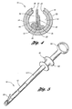
- Figure 6 is an elevated view of an endoscope apparatus implementing the cutting device in accordance with one embodiment of the present invention.
- Figure 7 is a side view of the endoscope apparatus in Figure 6 .
- the present invention generally comprises a cutting device that provides relatively sharp dissections regardless of the cut location along its blade, thereby minimizing shearing and broad cuts.
- the embodiments of the present invention comprise inner and outer catheters having open areas formed therethrough and configured to be aligned.
- the inner catheter includes a receiving member and a cutting blade that biasingly extends through the open area of the inner catheter.
- the outer catheter is slidably retractable to force the cutting blade inward and engage the receiving member to cut a suture or dissect a vessel or an organ. As a result, the likelihood of shearing is reduced.
- FIG. 1 illustrates an endoscopic cutting device 10 in accordance with one embodiment of the present invention.
- the cutting device 10 is compatible with an endoscope for endoscopy and cutting sutures.
- the cutting device 10 may be implemented for the following procedures: cutting sutures with an endoscope, gastroscopy, sigmoidoscopy and colonoscopy, esophago gastro duodenoscopy (EGD), endoscopic retrograde cholangiopancreatography (ERCP), and bronchoscopy.
- the cutting device 10 provides relatively sharp dissections regardless of the cut location along the blade, thereby avoiding shearing and broad cuts.
- the cutting device 10 comprises an inner catheter 12 having an inner wall 13 and an outer catheter 14 slidably disposed about the inner catheter 12.
- inner wall 13 has a proximal portion 16 and a closed distal portion 20.
- the inner catheter 12 may be made of any suitable material such as Nitinol or polymeric materials, e.g., low density polyethylene, polypropylene, polytetrafluoroethylene (PTFE) or mixtures thereof.
- the distal portion has a distal opening 22 longitudinally formed therethrough.
- the inner wall 13 further includes a spring mechanism 24 having first and second arms 26, 30 connected to each other at an apex or a cutting axis 32.
- the cutting axis 32 is preferably defined by the spring mechanism 24.
- the first and second arms 26, 30 are spring-loaded to biasingly extend away from each other relative the apex 32.
- the first arm 26 is attached to the inner wall 13 and the second arm 30 biasingly extends proximally from the first arm 26 through the opening 22.
- the first arm 26 remains stationary on the inner wall 13 while the second arm 30 is biasingly pivotable relative to the first arm 26.
- the spring mechanism 24 may be positioned such that the second arm 30 extends distally relative to the cutting device 10.
- the inner wall 13 further includes a cutting blade 34 attached to the second arm 30 of the spring mechanism 24 adjacent the distal opening 22.
- the cutting blade 34 comprises a cutting edge 35 for cutting and a back or non-cutting edge 37 opposite the cutting edge 35.
- the cutting blade 34 being spring-loaded by the spring mechanism 24, biasingly extends proximally through the distal opening 22 of the inner wall 13.
- the cutting blade 34 is pivotably moveable about the cutting axis 32 to cut sutures on the cutting edge 35.
- the cutting blade 34 may be made of any suitable material such as metal or high density polymer.
- Figures 3 and 4 depict the inner wall 13 further including a receiving assembly 36 disposed thereon.
- the receiving assembly 36 is disposed on the first arm 26 and is attached to the inner wall 13.
- the receiving assembly 36 is configured to cooperatively receive the cutting blade 34 for cutting.
- the receiving assembly 36 facilitates cutting as the cutting edge 35 of the cutting blade 34 is pivotally moved toward the first arm 30.
- the receiving assembly 36 has a base 40 for receiving the cutting edge 35 of the cutting blade 34.
- the base 40 is attached on the first arm 26 and extends across a portion of inner catheter 12 to facilitate stability of the spring mechanism 24.
- the receiving assembly may be made of any suitable material such as metal or high density polymer.
- the receiving assembly 36 further includes a receiving blade 42 extending from the base 40 and is configured to cooperate with the cutting blade 34 for cutting and dissecting.
- the cutting blade 34 is pivotally moved inwardly to engage with the receiving assembly 36. Cutting and dissecting are achieved by engaging the cutting edge of the cutting blade 34 with the receiving blade 42 to cut suture, vessel, or any other desirable item to be endoscopically cut.
- the cutting blade 34 is cooperatively received by the base 40 in notch 44.
- a drive wire 46 is disposed on the distal portion 20 of the inner wall 13 to position and manipulate the inner wall 13 within the body of a patient.
- a drive wire 46 is disposed on the distal portion 20 of the inner wall 13 to position and manipulate the inner wall 13 within the body of a patient.
- other suitable mechanisms may be implemented without falling beyond the scope or spirit of the present invention.
- the cutting device 10 further comprises the outer catheter 14 including an outer wall 50 having a proximal end 52 and an open distal end 54.
- the outer catheter 14 may be made of any suitable material such as Nitinol or polymeric materials, e.g., low density polyethylene, polypropylene, polytetrafluoroethylene (PTFE) or mixtures thereof.
- the outer catheter 14 is slidably disposed about the inner catheter 12.
- the distal end 54 is open to allow clearance for facilitating longitudinal movement of the outer catheter 14 about the inner catheter 12.
- the outer wall 50 includes an aperture 56 formed therethrough adjacent the distal end 54.
- the outer wall 50 is configured to slidably move relative to the inner catheter 12 and align the aperture 56 with the distal opening 22 of the inner wall 13.
- retraction of the outer catheter 14 allows engagement between the outer catheter 14 with the back edge 37 of the cutting blade 34, thereby moving the cutting blade 34 downwardly to biasingly engage with the receiving blade 42 for closing the blade and for cutting.
- the cutting blade 34 is received at the base 40 of the receiving assembly 36.
- the force of the outer catheter 14 on the cutting blade 34 is placed directly on an item for cutting, such as a suture.
- the cutting blade engages the receiving assembly 36 and the item is cut or dissected.
- Figure 5 illustrates controller 60 cooperable with the drive wire 46 and the inner and outer catheters 12, 14.
- the controller 60 includes a spool 62 connected to the drive wire 46 for movement of the inner catheter 12 relative to the outer catheter 14.
- the controller 60 further includes a handle 64 proximally connected to the outer catheter 14 and configured to facilitate movement thereof for cutting and dissection.
- FIGS 6 and 7 depict an endoscope apparatus 70 having the cutting device 10 in accordance with one embodiment of the present invention.
- the apparatus 70 may be used for cutting sutures and various other endoscopic procedures including gastroscopy, sigmoidoscopy and colonoscopy, esophago gastro duodenoscopy (EGD), endoscopic retrograde cholangiopancreatography (ERCP), and bronchoscopy.
- the cutting device 10 provides relatively sharp dissections regardless of the cut location along the blade 34, thereby minimizing shearing and broad cuts.
- the apparatus 70 comprises an endoscopic assembly 72 for endoscopy.
- the endoscopic assembly 72 includes an insertion tube 74 having a plurality of channel ports 75 through which endoscopic units may be disposed.
- the endoscopic units disposed in one of the ports may include one embodiment of the cutting device mentioned above, an endoscopic camera lens 80, a suction source 82, and a water/air flush 84.
- Other suitable units may be used as desired.
- the endoscopic assembly 72 further includes a control system 86 that is in mechanical and fluid communication with the insertion tube 74.
- the control system 86 is configured to control the insertion tube 74 and endoscopic parts disposed therein.
- the control system 86 includes first and second control knobs 87, 88.
- the control knobs 87, 88 are configured to be in mechanical communication with the insertion tube 74.
- the control knobs 87, 88 allow the physician to control and guide, by known means, the insertion tube 74 through vessels and cavities of a patient.
- the control system 86 further includes valve switches (e.g., suction valve 90, air/water valve 91, camera valve 92), each of which are in communication to one of the channel ports 75 of the insertion tube 74.
- the suction valve switch 90 when activated, allows a vacuum from a suction source through a suction channel port 82 for suctioning unwanted plaque and debris from the patient.
- the endoscopic apparatus 70 includes the endoscopic cutting device 10 described above.
- the endoscopic cutting device 10 is inserted through the biopsy/scissors channel port 76 of the endoscopic assembly 72.
- the device 10 is then fed through the respective biopsy channel port 76 of the endoscopic assembly 72.
- the cutting device 10 is preferably fed therethrough until the distal end 54 of the outer catheter 14 is adjacent nozzle 78 of the insertion tube 74.
- the endoscopic cutting device 10 comprises the inner catheter 12 having the cutting base 40 disposed thereon, the outer catheter 14 disposed about the inner catheter 12, and the drive wire 46 attached within the inner catheter 12.
- the distal end of the insertion tube 74 is inserted, rectally or orally, to a predetermined endoscopic location within a patient. Insertion of the insertion tube 74 may be rectally or orally depending on the endoscopic procedure.
- a physician may activate and control the endoscopic units as desired, such as to cut sutures previously surgically placed in a patient.
- the endoscope in combination with the cutting device of the present invention allows the physician to make sharp dissections and cuts as desired.
Description
- The present invention relates to endoscopic cutting devices and apparatus for medical procedures involving endoscopic procedures and cutting sutures.
- Endoscopic devices have been commonly used for various procedures, typically in the abdominal area. Endoscopy is the examination and inspection of the interior of body organs, joints or cavities through an endoscope. Endoscopy allows physicians to peer through the body's passageways. An endoscopic procedure may be used to diagnose various conditions by close examination of internal organs and body structures, and may also guide therapy and repair, such as the removal of torn cartilage from the bearing surfaces of a joint. A biopsy, a procedure involving tissue sampling for pathologic testing, may also be performed under endoscopic guidance. For example, endoscopic procedures include the following known procedures: gastroscopy, sigmoidoscopy and colonoscopy, esophago gastro duodenoscopy (EGD), endoscopic retrograde cholangiopancreatography (ERCP), and bronchoscopy.
- Typically, an endoscope uses two fiber optic lines. A "light fiber" emits light into a body cavity and an "image fiber" carries an image of the body cavity back to a viewing lens. Endoscopes may be used in conjunction with a camera or video recorder to document images of the inside of the joint or chronicle an endoscopic procedure. New endoscopes have digital capabilities for manipulating and enhancing the video images.
- An endoscope typically includes at least one separate port to allow for administration of drugs, suction, or irrigation. Such port(s) may also be used to introduce small folding instruments such as forceps, scissors, brushes, snares or baskets for tissue excision, sampling, or other diagnostic and therapeutic work.
- For example, endoscopic scissors and forceps may be configured to be used with a particular endoscope for sampling and excision purposes, and for cutting sutures. Although many current endoscopic scissors are adequate, improvements may be made. For instance, current endoscopic scissors typically have a pair of moveable jaws on which blades are disposed. As cuts are made distally from the apex of the jaws, the pressure or cutting effectiveness decreases. As a result, many cuts or dissections are relatively not sharp. When the scissor blades contact sutures (or other items to be cut) adjacent a distal portion of the blades, the results many times involve undesirable shearing.
- Thus, it is desirable to provide an improved cutting device compatible with an endoscope.
-
WO 98/11825 - The present invention generally provides a cutting device that is compatible with an endoscope for endoscopy. The cutting device includes blades that provide effective and relatively sharp dissections along any portion of the blades. The cutting device provides relatively sharp dissections regardless of the cut location along the blade, thereby avoiding shearing and broad cuts. As a result, shearing is avoided.
- One embodiment of the present invention provides an endoscopic cutting device. The device comprises an inner catheter including an inner wall having an opening formed therethrough. The inner wall further has a cutting blade moveably disposed thereon and biasingly extending through the opening. The inner wall has a receiving member disposed thereon and is configured to cooperatively receive the cutting blade. The device further comprises an outer catheter including an outer wall moveably disposed about the inner catheter. The outer wall has an aperture formed therethrough. The aperture is configured to moveably align with the opening of the inner wall for allowing the cutting blade to biasingly extend through the opening and biasingly engage the cutting blade with the receiving member to cut.
- In another embodiment, the cutting device comprises an inner catheter including an inner wall having a proximal portion and a closed distal portion. The distal portion has an opening formed therethrough. The inner wall further has a spring loaded cutting blade disposed thereon and biasingly extending through the opening. The inner wall has a receiving member disposed thereon and is configured to cooperatively receive the cutting blade.
- The cutting device further comprises an outer catheter including an outer wall having a proximal end and an open distal end. The outer wall is slidably disposed about the inner catheter. The outer wall has an aperture formed therethrough. The aperture of the outer wall is configured to align with the opening of the inner wall, allowing the cutting blade to biasingly extend therethrough and biasingly engage the receiving member to cut.
- In yet another embodiment, the present invention provides an endoscopic cutting apparatus. The apparatus comprises an inner catheter including an inner wall having a proximal portion and a closed distal portion. The distal portion has an opening formed therethrough. The inner wall further has a spring loaded cutting blade disposed thereon and biasingly extending through the opening. The inner wall has a receiving member disposed thereon and is configured to cooperatively receive the cutting blade.
- The apparatus further comprises an outer catheter including an outer wall having a proximal end and an open distal end. The outer wall is slidably disposed about the inner catheter. The outer wall has an aperture formed therethrough. The aperture of the outer wall is configured to align with the opening of the inner wall, allowing the cutting blade to biasingly extend therethrough and biasingly engage the receiving member to cut.
- Further objects, features, and advantages of the present invention will become apparent from consideration of the following description and the appended claims when taken in connection with the accompanying drawings.
-
Figure 1 is a partial side view of an endoscopic cutting device in accordance with one embodiment of the present invention; -
Figure 2 is another partial side view of the endoscopic cutting device ofFigure 1 ; -
Figure 3 is a cross-sectional view of the endoscopic cutting device ofFigure 2 taken along line 3-3; -
Figure 4 is another cross-sectional view of the endoscopic cutting device ofFigure 2 taken along line 4-4; -
Figure 5 is a break-away side view of the endoscopic cutting device ofFigure 2 ; -
Figure 6 is an elevated view of an endoscope apparatus implementing the cutting device in accordance with one embodiment of the present invention; and -
Figure 7 is a side view of the endoscope apparatus inFigure 6 . - The present invention generally comprises a cutting device that provides relatively sharp dissections regardless of the cut location along its blade, thereby minimizing shearing and broad cuts. The embodiments of the present invention comprise inner and outer catheters having open areas formed therethrough and configured to be aligned. The inner catheter includes a receiving member and a cutting blade that biasingly extends through the open area of the inner catheter. The outer catheter is slidably retractable to force the cutting blade inward and engage the receiving member to cut a suture or dissect a vessel or an organ. As a result, the likelihood of shearing is reduced.
-
Figure 1 illustrates anendoscopic cutting device 10 in accordance with one embodiment of the present invention. The cuttingdevice 10 is compatible with an endoscope for endoscopy and cutting sutures. For example, the cuttingdevice 10 may be implemented for the following procedures: cutting sutures with an endoscope, gastroscopy, sigmoidoscopy and colonoscopy, esophago gastro duodenoscopy (EGD), endoscopic retrograde cholangiopancreatography (ERCP), and bronchoscopy. The cuttingdevice 10 provides relatively sharp dissections regardless of the cut location along the blade, thereby avoiding shearing and broad cuts. - As shown in
Figures 2 and 3 , the cuttingdevice 10 comprises aninner catheter 12 having aninner wall 13 and anouter catheter 14 slidably disposed about theinner catheter 12. Preferably,inner wall 13 has aproximal portion 16 and a closeddistal portion 20. Theinner catheter 12 may be made of any suitable material such as Nitinol or polymeric materials, e.g., low density polyethylene, polypropylene, polytetrafluoroethylene (PTFE) or mixtures thereof. In this embodiment, the distal portion has adistal opening 22 longitudinally formed therethrough. - Preferably, the
inner wall 13 further includes aspring mechanism 24 having first andsecond arms axis 32. The cuttingaxis 32 is preferably defined by thespring mechanism 24. As shown, the first andsecond arms first arm 26 is attached to theinner wall 13 and thesecond arm 30 biasingly extends proximally from thefirst arm 26 through theopening 22. Thus, thefirst arm 26 remains stationary on theinner wall 13 while thesecond arm 30 is biasingly pivotable relative to thefirst arm 26. It is to be noted that thespring mechanism 24 may be positioned such that thesecond arm 30 extends distally relative to thecutting device 10. - As shown, the
inner wall 13 further includes acutting blade 34 attached to thesecond arm 30 of thespring mechanism 24 adjacent thedistal opening 22. In this embodiment, thecutting blade 34 comprises acutting edge 35 for cutting and a back ornon-cutting edge 37 opposite thecutting edge 35. Thus, thecutting blade 34, being spring-loaded by thespring mechanism 24, biasingly extends proximally through thedistal opening 22 of theinner wall 13. Moreover, thecutting blade 34 is pivotably moveable about the cuttingaxis 32 to cut sutures on thecutting edge 35. Thecutting blade 34 may be made of any suitable material such as metal or high density polymer. -
Figures 3 and4 depict theinner wall 13 further including a receivingassembly 36 disposed thereon. In this embodiment, the receivingassembly 36 is disposed on thefirst arm 26 and is attached to theinner wall 13. As shown, the receivingassembly 36 is configured to cooperatively receive thecutting blade 34 for cutting. The receivingassembly 36 facilitates cutting as thecutting edge 35 of thecutting blade 34 is pivotally moved toward thefirst arm 30. In this embodiment, the receivingassembly 36 has abase 40 for receiving thecutting edge 35 of thecutting blade 34. As shown, thebase 40 is attached on thefirst arm 26 and extends across a portion ofinner catheter 12 to facilitate stability of thespring mechanism 24. The receiving assembly may be made of any suitable material such as metal or high density polymer. - As shown, the receiving
assembly 36 further includes a receivingblade 42 extending from thebase 40 and is configured to cooperate with thecutting blade 34 for cutting and dissecting. As described in greater detail below, thecutting blade 34 is pivotally moved inwardly to engage with the receivingassembly 36. Cutting and dissecting are achieved by engaging the cutting edge of thecutting blade 34 with the receivingblade 42 to cut suture, vessel, or any other desirable item to be endoscopically cut. Thecutting blade 34 is cooperatively received by the base 40 innotch 44. - In this embodiment a
drive wire 46 is disposed on thedistal portion 20 of theinner wall 13 to position and manipulate theinner wall 13 within the body of a patient. However, other suitable mechanisms may be implemented without falling beyond the scope or spirit of the present invention. - As shown, the cutting
device 10 further comprises theouter catheter 14 including anouter wall 50 having aproximal end 52 and an opendistal end 54. Theouter catheter 14 may be made of any suitable material such as Nitinol or polymeric materials, e.g., low density polyethylene, polypropylene, polytetrafluoroethylene (PTFE) or mixtures thereof. Theouter catheter 14 is slidably disposed about theinner catheter 12. Thedistal end 54 is open to allow clearance for facilitating longitudinal movement of theouter catheter 14 about theinner catheter 12. Theouter wall 50 includes anaperture 56 formed therethrough adjacent thedistal end 54. Theouter wall 50 is configured to slidably move relative to theinner catheter 12 and align theaperture 56 with thedistal opening 22 of theinner wall 13. - In this embodiment, retraction of the
outer catheter 14 allows engagement between theouter catheter 14 with theback edge 37 of thecutting blade 34, thereby moving thecutting blade 34 downwardly to biasingly engage with the receivingblade 42 for closing the blade and for cutting. Thecutting blade 34 is received at thebase 40 of the receivingassembly 36. Thus, the force of theouter catheter 14 on thecutting blade 34 is placed directly on an item for cutting, such as a suture. As theouter catheter 14 rides along thecutting blade 34 and forces the cutting blade inwardly, the cutting blade engages the receivingassembly 36 and the item is cut or dissected. -
Figure 5 illustratescontroller 60 cooperable with thedrive wire 46 and the inner andouter catheters controller 60 includes aspool 62 connected to thedrive wire 46 for movement of theinner catheter 12 relative to theouter catheter 14. Thecontroller 60 further includes ahandle 64 proximally connected to theouter catheter 14 and configured to facilitate movement thereof for cutting and dissection. -
Figures 6 and 7 depict anendoscope apparatus 70 having the cuttingdevice 10 in accordance with one embodiment of the present invention. Theapparatus 70 may be used for cutting sutures and various other endoscopic procedures including gastroscopy, sigmoidoscopy and colonoscopy, esophago gastro duodenoscopy (EGD), endoscopic retrograde cholangiopancreatography (ERCP), and bronchoscopy. By way of theendoscope apparatus 70, the cuttingdevice 10 provides relatively sharp dissections regardless of the cut location along theblade 34, thereby minimizing shearing and broad cuts. - As shown, the
apparatus 70 comprises an endoscopic assembly 72 for endoscopy. The endoscopic assembly 72 includes aninsertion tube 74 having a plurality of channel ports 75 through which endoscopic units may be disposed. In one embodiment, the endoscopic units disposed in one of the ports may include one embodiment of the cutting device mentioned above, anendoscopic camera lens 80, asuction source 82, and a water/air flush 84. Other suitable units may be used as desired. - As shown, the endoscopic assembly 72 further includes a
control system 86 that is in mechanical and fluid communication with theinsertion tube 74. Thecontrol system 86 is configured to control theinsertion tube 74 and endoscopic parts disposed therein. As shown, thecontrol system 86 includes first and second control knobs 87, 88. The control knobs 87, 88 are configured to be in mechanical communication with theinsertion tube 74. The control knobs 87, 88 allow the physician to control and guide, by known means, theinsertion tube 74 through vessels and cavities of a patient. Thecontrol system 86 further includes valve switches (e.g.,suction valve 90, air/water valve 91, camera valve 92), each of which are in communication to one of the channel ports 75 of theinsertion tube 74. For example, thesuction valve switch 90, when activated, allows a vacuum from a suction source through asuction channel port 82 for suctioning unwanted plaque and debris from the patient. - As shown in
Figures 6 and 7 , theendoscopic apparatus 70 includes theendoscopic cutting device 10 described above. In this embodiment, theendoscopic cutting device 10 is inserted through the biopsy/scissors channel port 76 of the endoscopic assembly 72. Thedevice 10 is then fed through the respectivebiopsy channel port 76 of the endoscopic assembly 72. The cuttingdevice 10 is preferably fed therethrough until thedistal end 54 of theouter catheter 14 isadjacent nozzle 78 of theinsertion tube 74. - As mentioned above, the
endoscopic cutting device 10 comprises theinner catheter 12 having the cuttingbase 40 disposed thereon, theouter catheter 14 disposed about theinner catheter 12, and thedrive wire 46 attached within theinner catheter 12. - In one example, the distal end of the
insertion tube 74 is inserted, rectally or orally, to a predetermined endoscopic location within a patient. Insertion of theinsertion tube 74 may be rectally or orally depending on the endoscopic procedure. At the location, a physician may activate and control the endoscopic units as desired, such as to cut sutures previously surgically placed in a patient. The endoscope in combination with the cutting device of the present invention allows the physician to make sharp dissections and cuts as desired. - While the present invention has been described in terms of preferred embodiments, it will be understood, of course, that the invention is not limited thereto since modifications may be made to those skilled in the art, particularly in light of the foregoing teachings.
Claims (12)
- An endoscopic cutting device, the device comprising:an inner catheter including an inner wall having an opening formed therethrough, the inner wall further having a cutting blade moveably disposed thereon and biasingly extending through the opening, the inner wall having a receiving member disposed thereon and being configured to cooperatively receive the cutting blade; andan outer catheter including an outer wall moveably disposed about the inner catheter, the outer wall having an aperture formed therethrough, the aperture of the outer wall being configured to moveably align with the opening of the inner wall for allowing the cutting blade to biasingly extend through the opening and biasingly engage the cutting blade with the receiving member to cut.
- The cutting device of claim 1 wherein the inner wall has a proximal portion and a distal portion, the opening being formed through the distal portion.
- The cutting device of claim 2 wherein the distal portion has a closed distal end.
- The cutting device of claim 1 further comprising a drive wire disposed on the distal portion of the inner wall for positioning the inner wall within the body of the patient.
- The cutting device of claim 1 wherein the cutting blade is spring loaded to biasingly extend from the inner wall.
- The cutting device of claim 1 wherein the outer wall has a proximal end and a distal end, the distal end being open to slidably move about the inner wall.
- The cutting device of claim 1 wherein the outer wall is slidably disposed about the inner wall.
- The cutting device of claim 1 wherein the receiving member is a receiving assembly having a base for receiving the cutting blade, the receiving assembly further having a receiving blade extending from the base and being configured to cooperate with the cutting blade for cutting.
- The cutting device of claim 8 wherein the inner wall further includes:a spring mechanism having first and second arms, the first arm being attached to the inner wall and the second arm biasingly extending from the first arm and through the opening, the second arm biasingly moveable relative to the first arm, the receiving assembly being disposed on the first arm and attached to the inner wall, the cutting blade being disposed on the second arm and being moveable for cutting.
- The cutting device of claim 9 wherein the second arm is biasingly pivotable about a cutting axis of the cutting blade, the cutting axis being defined by the spring.
- The cutting device of claim 1 wherein the cutting blade comprises a cutting edge for cutting and a back edge opposite the cutting edge.
- The cutting device of claim 11 wherein the outer catheter engages the back edge of the cutting blade to move the cutting blade downwardly to biasingly engage with the receiving blade for closing the blade and cutting.
Applications Claiming Priority (2)
| Application Number | Priority Date | Filing Date | Title |
|---|---|---|---|
| US64751705P | 2005-01-27 | 2005-01-27 | |
| PCT/US2006/002802 WO2006083679A1 (en) | 2005-01-27 | 2006-01-27 | Endoscopic cutting device |
Publications (2)
| Publication Number | Publication Date |
|---|---|
| EP1841365A1 EP1841365A1 (en) | 2007-10-10 |
| EP1841365B1 true EP1841365B1 (en) | 2013-07-24 |
Family
ID=36481372
Family Applications (1)
| Application Number | Title | Priority Date | Filing Date |
|---|---|---|---|
| EP06733928.3A Active EP1841365B1 (en) | 2005-01-27 | 2006-01-27 | Endoscopic cutting device |
Country Status (6)
| Country | Link |
|---|---|
| US (1) | US7520886B2 (en) |
| EP (1) | EP1841365B1 (en) |
| JP (1) | JP4751401B2 (en) |
| AU (1) | AU2006211174B2 (en) |
| CA (1) | CA2596249C (en) |
| WO (1) | WO2006083679A1 (en) |
Families Citing this family (81)
| Publication number | Priority date | Publication date | Assignee | Title |
|---|---|---|---|---|
| US7678151B2 (en) | 2000-05-01 | 2010-03-16 | Ek Steven W | System and method for joint resurface repair |
| US7163541B2 (en) | 2002-12-03 | 2007-01-16 | Arthrosurface Incorporated | Tibial resurfacing system |
| US6610067B2 (en) | 2000-05-01 | 2003-08-26 | Arthrosurface, Incorporated | System and method for joint resurface repair |
| EP2314257B9 (en) | 2000-05-01 | 2013-02-27 | ArthroSurface, Inc. | System for joint resurface repair |
| US8177841B2 (en) | 2000-05-01 | 2012-05-15 | Arthrosurface Inc. | System and method for joint resurface repair |
| US7901408B2 (en) | 2002-12-03 | 2011-03-08 | Arthrosurface, Inc. | System and method for retrograde procedure |
| US8388624B2 (en) | 2003-02-24 | 2013-03-05 | Arthrosurface Incorporated | Trochlear resurfacing system and method |
| CA2546582A1 (en) | 2003-11-20 | 2005-06-09 | Arthrosurface, Inc. | Retrograde delivery of resurfacing devices |
| AU2006203909A1 (en) * | 2003-11-20 | 2006-07-13 | Arthrosurface, Inc. | System and method for retrograde procedure |
| US8425539B2 (en) | 2004-04-12 | 2013-04-23 | Xlumena, Inc. | Luminal structure anchoring devices and methods |
| WO2006004885A2 (en) | 2004-06-28 | 2006-01-12 | Arthrosurface, Inc. | System for articular surface replacement |
| US7828853B2 (en) | 2004-11-22 | 2010-11-09 | Arthrosurface, Inc. | Articular surface implant and delivery system |
| EP3511047B1 (en) | 2004-12-08 | 2024-03-13 | Boston Scientific Scimed, Inc. | Apparatus for performing needle guided interventions |
| US8784437B2 (en) | 2005-06-09 | 2014-07-22 | Xlumena, Inc. | Methods and devices for endosonography-guided fundoplexy |
| US8777967B2 (en) | 2005-06-09 | 2014-07-15 | Xlumena, Inc. | Methods and devices for anchoring to tissue |
| US20070225740A1 (en) * | 2006-02-22 | 2007-09-27 | Loubert Suddaby | Endoscopic Pulley Knife Instrument for Transecting Ligaments or Fascia |
| WO2008022087A2 (en) * | 2006-08-11 | 2008-02-21 | Mynosys Cellular Devices, Inc. | Three-dimensional cutting instrument |
| US7918784B2 (en) * | 2006-08-18 | 2011-04-05 | Microaire Surgical Instruments, Inc. | Endoscopic surgical tool with retractable blade for carpal tunnel release |
| US9358029B2 (en) | 2006-12-11 | 2016-06-07 | Arthrosurface Incorporated | Retrograde resection apparatus and method |
| WO2009111481A1 (en) | 2008-03-03 | 2009-09-11 | Arthrosurface Incorporated | Bone resurfacing system and method |
| US8454632B2 (en) | 2008-05-12 | 2013-06-04 | Xlumena, Inc. | Tissue anchor for securing tissue layers |
| US8303594B2 (en) * | 2008-12-30 | 2012-11-06 | Howmedica Osteonics Corp. | Method and apparatus for removal of tissue |
| FR2943237B1 (en) * | 2009-03-20 | 2012-11-30 | Alexandre Worcel | ENDOSCOPIC CUTTING SURGICAL DEVICE |
| US10945743B2 (en) | 2009-04-17 | 2021-03-16 | Arthrosurface Incorporated | Glenoid repair system and methods of use thereof |
| WO2010121250A1 (en) | 2009-04-17 | 2010-10-21 | Arthrosurface Incorporated | Glenoid resurfacing system and method |
| WO2010121246A1 (en) * | 2009-04-17 | 2010-10-21 | Arthrosurface Incorporated | Glenoid resurfacing system and method |
| US9364259B2 (en) * | 2009-04-21 | 2016-06-14 | Xlumena, Inc. | System and method for delivering expanding trocar through a sheath |
| WO2010138277A1 (en) | 2009-05-29 | 2010-12-02 | Xlumena, Inc. | Apparatus and method for deploying stent across adjacent tissue layers |
| US8701295B2 (en) * | 2009-11-20 | 2014-04-22 | Joseph Clearman | Variable pressure cutting devices |
| US8316493B2 (en) | 2009-11-20 | 2012-11-27 | Joseph H. Clearman | Bag closure |
| CA2792048A1 (en) | 2010-03-05 | 2011-09-09 | Arthrosurface Incorporated | Tibial resurfacing system and method |
| EP2364653A1 (en) * | 2010-03-11 | 2011-09-14 | Tyco Healthcare Group LP | Insertion device and method of use |
| US8771306B2 (en) | 2010-03-11 | 2014-07-08 | Covidien Lp | Insertion device and method of use |
| SG184362A1 (en) * | 2010-03-30 | 2012-11-29 | Singapore Health Serv Pte Ltd | Cutting device for cutting tissue |
| US8876845B2 (en) | 2010-09-30 | 2014-11-04 | Loubert Suddaby | Sling blade transection of the transverse carpal ligament |
| US8784420B2 (en) | 2010-10-13 | 2014-07-22 | Warsaw Orthopedic, Inc. | Surgical instruments for cutting elongated elements and methods of use |
| US10070908B2 (en) | 2010-10-13 | 2018-09-11 | Warsaw Orthopedic, Inc. | Surgical instruments for cutting elongated elements and methods of use |
| WO2012060932A2 (en) | 2010-10-25 | 2012-05-10 | Endosee Corporation | Method and apparatus for hysteroscopy and endometrial biopsy |
| US9066716B2 (en) | 2011-03-30 | 2015-06-30 | Arthrosurface Incorporated | Suture coil and suture sheath for tissue repair |
| CA2833549A1 (en) * | 2011-04-18 | 2012-10-26 | Eastern Virginia Medical School | Cerclage suture removal device |
| EP2709513A4 (en) | 2011-05-03 | 2015-04-22 | Endosee Corp | Method and apparatus for hysteroscopy and endometrial biopsy |
| US20130165982A1 (en) | 2011-12-22 | 2013-06-27 | Arthrosurface Incorporated | System and Method for Bone Fixation |
| WO2013102235A1 (en) * | 2012-01-06 | 2013-07-11 | Jiwan Steven Singh | An insert and insert system for a laparoscopic instrument |
| EP2811923B1 (en) | 2012-02-07 | 2019-10-16 | Intervene, Inc. | System for endoluminal valve creation |
| EP2854654B1 (en) | 2012-05-17 | 2019-11-06 | Boston Scientific Scimed, Inc. | Devices for access across adjacent tissue layers |
| US9364260B2 (en) * | 2012-05-25 | 2016-06-14 | Depuy Mitek, Llc | Method for atraumatic hip access |
| US9622646B2 (en) | 2012-06-25 | 2017-04-18 | Coopersurgical, Inc. | Low-cost instrument for endoscopically guided operative procedures |
| WO2014008126A1 (en) | 2012-07-03 | 2014-01-09 | Arthrosurface Incorporated | System and method for joint resurfacing and repair |
| WO2014055981A1 (en) | 2012-10-05 | 2014-04-10 | Board Of Regents, The University Of Texas System | System and method for scoring the left ventricular endocardium to increase left ventricular compliance |
| WO2014093068A1 (en) | 2012-12-12 | 2014-06-19 | Covidien Lp | Tissue-removing catheter including screw blade and cutter driveshaft |
| US9636139B2 (en) | 2012-12-12 | 2017-05-02 | Covidien Lp | Tissue-removing catheter with ball and socket deployment mechanism |
| JP6110509B2 (en) | 2012-12-12 | 2017-04-05 | コヴィディエン リミテッド パートナーシップ | Tissue removal catheter including pressing mechanism |
| US9636138B2 (en) | 2012-12-12 | 2017-05-02 | Covidien Lp | Tissue-removing catheter including force-transmitting member for actuating a cutter housing |
| JP6502260B2 (en) | 2012-12-12 | 2019-04-17 | コヴィディエン リミテッド パートナーシップ | Tissue removal catheter for body lumens |
| EP2931148B1 (en) | 2012-12-12 | 2016-09-21 | Covidien LP | Cutter for tissue-removing catheter |
| WO2014110460A1 (en) | 2013-01-10 | 2014-07-17 | Intervene, Inc. | Systems and methods for endoluminal valve creation |
| JP6342431B2 (en) | 2013-02-21 | 2018-06-13 | ボストン サイエンティフィック サイムド,インコーポレイテッドBoston Scientific Scimed,Inc. | Stent for forming anastomosis and medical device including the stent |
| US9402644B2 (en) * | 2013-03-13 | 2016-08-02 | Covidien Lp | Reverse seam ripper dissector |
| US9492200B2 (en) | 2013-04-16 | 2016-11-15 | Arthrosurface Incorporated | Suture system and method |
| US10433861B2 (en) | 2013-08-27 | 2019-10-08 | Board Of Regents Of The University Of Texas System | System and method for cutting trabeculae carneae of the left ventricle to increase LV compliance |
| WO2015048565A2 (en) | 2013-09-27 | 2015-04-02 | Intervene, Inc. | Visualization devices, systems, and methods for informing intravascular procedures on blood vessel valves |
| US20150250472A1 (en) | 2014-03-07 | 2015-09-10 | Arthrosurface Incorporated | Delivery System for Articular Surface Implant |
| US10624748B2 (en) | 2014-03-07 | 2020-04-21 | Arthrosurface Incorporated | System and method for repairing articular surfaces |
| US11607319B2 (en) | 2014-03-07 | 2023-03-21 | Arthrosurface Incorporated | System and method for repairing articular surfaces |
| US10188419B2 (en) | 2014-03-24 | 2019-01-29 | Intervene, Inc. | Visualization devices for use during percutaneous tissue dissection and associated systems and methods |
| WO2016044072A1 (en) | 2014-09-18 | 2016-03-24 | Mayo Foundation For Medical Education And Research | Soft tissue cutting device and methods of use |
| WO2016100574A2 (en) | 2014-12-16 | 2016-06-23 | Intervene, Inc. | Intravascular devices, systems, and methods for the controlled dissection of body lumens |
| US20170071788A1 (en) * | 2015-09-15 | 2017-03-16 | Novartis Ag | Curved vitrectomy probe |
| US10702305B2 (en) | 2016-03-23 | 2020-07-07 | Coopersurgical, Inc. | Operative cannulas and related methods |
| US10646247B2 (en) | 2016-04-01 | 2020-05-12 | Intervene, Inc. | Intraluminal tissue modifying systems and associated devices and methods |
| US10456161B2 (en) | 2016-04-14 | 2019-10-29 | Covidien Lp | Tissue-removing catheter with adjustment mechanism |
| CN107184246A (en) * | 2017-06-26 | 2017-09-22 | 苏州奥特科然医疗科技有限公司 | Sclerotin cutting apparatus in a kind of bone |
| CA3108761A1 (en) | 2017-08-04 | 2019-02-07 | Arthrosurface Incorporated | Multicomponent articular surface implant |
| US10864055B2 (en) | 2017-10-13 | 2020-12-15 | Sonex Health, Inc. | Tray for a soft tissue cutting device and methods of use |
| JP6964766B2 (en) * | 2018-04-26 | 2021-11-10 | オリンパス株式会社 | Treatment system and expansion device |
| US11937845B2 (en) | 2019-01-11 | 2024-03-26 | Mayo Foundation For Medical Education And Research | Micro-invasive surgical device and methods of use |
| GB2616360B (en) | 2019-03-12 | 2023-11-29 | Arthrosurface Inc | Humeral and glenoid articular surface implant systems and methods |
| CN109833088A (en) * | 2019-03-13 | 2019-06-04 | 郑州大学第一附属医院 | The linear cutting device of hysteroscope pipe side wall |
| WO2021262785A1 (en) | 2020-06-23 | 2021-12-30 | Intervene, Inc. | Endovascular valve formation system with imaging capability |
| US11793599B2 (en) | 2020-08-04 | 2023-10-24 | Mazor Robotics Ltd. | Surgical cleaning tool, systems, and methods |
| USD989961S1 (en) | 2021-04-30 | 2023-06-20 | Sonex Health, Inc. | Soft tissue cutting device |
Family Cites Families (12)
| Publication number | Priority date | Publication date | Assignee | Title |
|---|---|---|---|---|
| US4963147A (en) * | 1987-09-18 | 1990-10-16 | John M. Agee | Surgical instrument |
| US5201759A (en) * | 1991-04-29 | 1993-04-13 | Ferzli George S | Laparoscopic instrument |
| US5304190A (en) * | 1992-05-08 | 1994-04-19 | Ethicon, Inc. | Endoscopic cutting apparatus |
| CA2181469A1 (en) * | 1994-01-18 | 1995-07-20 | Richard P. Fleenor | Knot tying method and apparatus |
| DE4403602A1 (en) * | 1994-02-07 | 1995-08-10 | Storz Karl Gmbh & Co | Endoscopic cutting device |
| US6193715B1 (en) * | 1999-03-19 | 2001-02-27 | Medical Scientific, Inc. | Device for converting a mechanical cutting device to an electrosurgical cutting device |
| US6638233B2 (en) * | 1999-08-19 | 2003-10-28 | Fox Hollow Technologies, Inc. | Apparatus and methods for material capture and removal |
| US6616661B2 (en) * | 2001-09-28 | 2003-09-09 | Ethicon, Inc. | Surgical device for clamping, ligating, and severing tissue |
| US8172856B2 (en) * | 2002-08-02 | 2012-05-08 | Cedars-Sinai Medical Center | Methods and apparatus for atrioventricular valve repair |
| US20040254598A1 (en) | 2003-06-16 | 2004-12-16 | Schumacher Brian S. | Suture cutter |
| EP1663014B1 (en) * | 2003-09-11 | 2008-08-13 | NMT Medical, Inc. | Suture sever tube |
| US7029435B2 (en) * | 2003-10-16 | 2006-04-18 | Granit Medical Innovation, Llc | Endoscope having multiple working segments |
-
2006
- 2006-01-27 WO PCT/US2006/002802 patent/WO2006083679A1/en active Application Filing
- 2006-01-27 CA CA2596249A patent/CA2596249C/en active Active
- 2006-01-27 EP EP06733928.3A patent/EP1841365B1/en active Active
- 2006-01-27 AU AU2006211174A patent/AU2006211174B2/en active Active
- 2006-01-27 US US11/341,298 patent/US7520886B2/en active Active
- 2006-01-27 JP JP2007553232A patent/JP4751401B2/en not_active Expired - Fee Related
Also Published As
| Publication number | Publication date |
|---|---|
| US20060184187A1 (en) | 2006-08-17 |
| AU2006211174B2 (en) | 2012-05-31 |
| CA2596249A1 (en) | 2006-08-10 |
| CA2596249C (en) | 2013-12-10 |
| AU2006211174A1 (en) | 2006-08-10 |
| JP2008534029A (en) | 2008-08-28 |
| US7520886B2 (en) | 2009-04-21 |
| EP1841365A1 (en) | 2007-10-10 |
| WO2006083679A1 (en) | 2006-08-10 |
| JP4751401B2 (en) | 2011-08-17 |
Similar Documents
| Publication | Publication Date | Title |
|---|---|---|
| EP1841365B1 (en) | Endoscopic cutting device | |
| JP2008534029A5 (en) | ||
| US5586990A (en) | Endosurgical instrument with a radially movable end effector | |
| US7060024B2 (en) | Apparatus for guiding an instrument used with an endoscope | |
| US7300445B2 (en) | Full thickness resection device | |
| US8083666B2 (en) | Endoscopic resection devices and related methods of use | |
| US7077803B2 (en) | Living tissue harvesting apparatus | |
| AU716048B2 (en) | Apparatus and method for performing colon/rectal surgery | |
| EP0904000B1 (en) | Spring based multi-purpose medical instrument | |
| JP4157183B2 (en) | Endoscopic treatment tool | |
| US7691055B2 (en) | Endoscopic apparatus having an improved elevator | |
| US8945153B2 (en) | Endoscopic apparatus having a clip device | |
| US9872600B2 (en) | Tissue resection bander and related methods of use | |
| US20080255589A1 (en) | Multi-function clipping and harvesting device | |
| US20110152610A1 (en) | Intralumenal accessory tip for endoscopic sheath arrangements | |
| WO2012114569A1 (en) | Three-dimensional retractor | |
| US20070208220A1 (en) | Endoscopic delivery apparatus having a catheter with radial grooves | |
| US20110105838A1 (en) | Suction device for endoscopic instruments and method | |
| US9844649B2 (en) | Telescopic wire guide | |
| CN116997299A (en) | System for multidirectional bending | |
| AU6551699A (en) | Apparatus and method for performing colon/rectal surgery |
Legal Events
| Date | Code | Title | Description |
|---|---|---|---|
| PUAI | Public reference made under article 153(3) epc to a published international application that has entered the european phase |
Free format text: ORIGINAL CODE: 0009012 |
|
| 17P | Request for examination filed |
Effective date: 20070802 |
|
| AK | Designated contracting states |
Kind code of ref document: A1 Designated state(s): DE GB IE |
|
| DAX | Request for extension of the european patent (deleted) | ||
| RBV | Designated contracting states (corrected) |
Designated state(s): DE GB IE |
|
| RAP1 | Party data changed (applicant data changed or rights of an application transferred) |
Owner name: COOK MEDICAL TECHNOLOGIES LLC |
|
| RAP1 | Party data changed (applicant data changed or rights of an application transferred) |
Owner name: COOK MEDICAL TECHNOLOGIES LLC |
|
| GRAP | Despatch of communication of intention to grant a patent |
Free format text: ORIGINAL CODE: EPIDOSNIGR1 |
|
| GRAS | Grant fee paid |
Free format text: ORIGINAL CODE: EPIDOSNIGR3 |
|
| GRAA | (expected) grant |
Free format text: ORIGINAL CODE: 0009210 |
|
| AK | Designated contracting states |
Kind code of ref document: B1 Designated state(s): DE GB IE |
|
| REG | Reference to a national code |
Ref country code: GB Ref legal event code: FG4D |
|
| RIN1 | Information on inventor provided before grant (corrected) |
Inventor name: SURTI, VIHAR, C. |
|
| REG | Reference to a national code |
Ref country code: IE Ref legal event code: FG4D |
|
| REG | Reference to a national code |
Ref country code: DE Ref legal event code: R096 Ref document number: 602006037503 Country of ref document: DE Effective date: 20130919 |
|
| PLBE | No opposition filed within time limit |
Free format text: ORIGINAL CODE: 0009261 |
|
| STAA | Information on the status of an ep patent application or granted ep patent |
Free format text: STATUS: NO OPPOSITION FILED WITHIN TIME LIMIT |
|
| 26N | No opposition filed |
Effective date: 20140425 |
|
| REG | Reference to a national code |
Ref country code: DE Ref legal event code: R097 Ref document number: 602006037503 Country of ref document: DE Effective date: 20140425 |
|
| PGFP | Annual fee paid to national office [announced via postgrant information from national office to epo] |
Ref country code: DE Payment date: 20221215 Year of fee payment: 18 |
|
| P01 | Opt-out of the competence of the unified patent court (upc) registered |
Effective date: 20230602 |
|
| PGFP | Annual fee paid to national office [announced via postgrant information from national office to epo] |
Ref country code: GB Payment date: 20231218 Year of fee payment: 19 |
|
| PGFP | Annual fee paid to national office [announced via postgrant information from national office to epo] |
Ref country code: IE Payment date: 20231228 Year of fee payment: 19 |