EP1841482B1 - Reinforcing member for a patient interface - Google Patents
Reinforcing member for a patient interface Download PDFInfo
- Publication number
- EP1841482B1 EP1841482B1 EP06704769.6A EP06704769A EP1841482B1 EP 1841482 B1 EP1841482 B1 EP 1841482B1 EP 06704769 A EP06704769 A EP 06704769A EP 1841482 B1 EP1841482 B1 EP 1841482B1
- Authority
- EP
- European Patent Office
- Prior art keywords
- cushion
- reinforcing member
- face
- patient interface
- contacting portion
- Prior art date
- Legal status (The legal status is an assumption and is not a legal conclusion. Google has not performed a legal analysis and makes no representation as to the accuracy of the status listed.)
- Revoked
Links
- 0 CCCCCC(CC1)C1C(CC1(C2)C=CC1)*C2=C Chemical compound CCCCCC(CC1)C1C(CC1(C2)C=CC1)*C2=C 0.000 description 2
Images


Classifications
-
- A—HUMAN NECESSITIES
- A61—MEDICAL OR VETERINARY SCIENCE; HYGIENE
- A61M—DEVICES FOR INTRODUCING MEDIA INTO, OR ONTO, THE BODY; DEVICES FOR TRANSDUCING BODY MEDIA OR FOR TAKING MEDIA FROM THE BODY; DEVICES FOR PRODUCING OR ENDING SLEEP OR STUPOR
- A61M16/00—Devices for influencing the respiratory system of patients by gas treatment, e.g. mouth-to-mouth respiration; Tracheal tubes
- A61M16/06—Respiratory or anaesthetic masks
- A61M16/0605—Means for improving the adaptation of the mask to the patient
- A61M16/0611—Means for improving the adaptation of the mask to the patient with a gusset portion
-
- A—HUMAN NECESSITIES
- A61—MEDICAL OR VETERINARY SCIENCE; HYGIENE
- A61M—DEVICES FOR INTRODUCING MEDIA INTO, OR ONTO, THE BODY; DEVICES FOR TRANSDUCING BODY MEDIA OR FOR TAKING MEDIA FROM THE BODY; DEVICES FOR PRODUCING OR ENDING SLEEP OR STUPOR
- A61M16/00—Devices for influencing the respiratory system of patients by gas treatment, e.g. mouth-to-mouth respiration; Tracheal tubes
- A61M16/06—Respiratory or anaesthetic masks
- A61M16/0605—Means for improving the adaptation of the mask to the patient
- A61M16/0616—Means for improving the adaptation of the mask to the patient with face sealing means comprising a flap or membrane projecting inwards, such that sealing increases with increasing inhalation gas pressure
- A61M16/0622—Means for improving the adaptation of the mask to the patient with face sealing means comprising a flap or membrane projecting inwards, such that sealing increases with increasing inhalation gas pressure having an underlying cushion
-
- A—HUMAN NECESSITIES
- A61—MEDICAL OR VETERINARY SCIENCE; HYGIENE
- A61M—DEVICES FOR INTRODUCING MEDIA INTO, OR ONTO, THE BODY; DEVICES FOR TRANSDUCING BODY MEDIA OR FOR TAKING MEDIA FROM THE BODY; DEVICES FOR PRODUCING OR ENDING SLEEP OR STUPOR
- A61M16/00—Devices for influencing the respiratory system of patients by gas treatment, e.g. mouth-to-mouth respiration; Tracheal tubes
- A61M16/06—Respiratory or anaesthetic masks
- A61M16/0605—Means for improving the adaptation of the mask to the patient
- A61M16/0633—Means for improving the adaptation of the mask to the patient with forehead support
-
- A—HUMAN NECESSITIES
- A61—MEDICAL OR VETERINARY SCIENCE; HYGIENE
- A61M—DEVICES FOR INTRODUCING MEDIA INTO, OR ONTO, THE BODY; DEVICES FOR TRANSDUCING BODY MEDIA OR FOR TAKING MEDIA FROM THE BODY; DEVICES FOR PRODUCING OR ENDING SLEEP OR STUPOR
- A61M16/00—Devices for influencing the respiratory system of patients by gas treatment, e.g. mouth-to-mouth respiration; Tracheal tubes
- A61M16/06—Respiratory or anaesthetic masks
- A61M16/0683—Holding devices therefor
-
- A—HUMAN NECESSITIES
- A61—MEDICAL OR VETERINARY SCIENCE; HYGIENE
- A61M—DEVICES FOR INTRODUCING MEDIA INTO, OR ONTO, THE BODY; DEVICES FOR TRANSDUCING BODY MEDIA OR FOR TAKING MEDIA FROM THE BODY; DEVICES FOR PRODUCING OR ENDING SLEEP OR STUPOR
- A61M16/00—Devices for influencing the respiratory system of patients by gas treatment, e.g. mouth-to-mouth respiration; Tracheal tubes
- A61M16/08—Bellows; Connecting tubes ; Water traps; Patient circuits
- A61M16/0816—Joints or connectors
- A61M16/0825—Joints or connectors with ball-sockets
Definitions
- the present invention relates to a reinforcing member for a patient interface, the patient interface being used in the treatment, e.g., of Sleep Disordered Breathing (SDB) with Non-Invasive Positive Pressure Ventilation (NIPPV).
- SDB Sleep Disordered Breathing
- NIPPV Non-Invasive Positive Pressure Ventilation
- Patient interfaces typically include a rigid shell or frame and a soft face-contacting cushion.
- the cushion spaces the frame away from the patient's face.
- the frame and cushion define a cavity which receives the patient's nose or nose and mouth.
- the frame and cushion are held in position on the patient's face by a headgear assembly.
- a known patient interface commercially sold under the name of Activa® by ResMed Ltd., includes a cushion having a gusset portion. Further details and embodiments of this cushion are disclosed in U.S. Patent US 2004/118406 A1 .
- the gusset portion is positioned between the frame-contacting side and the face-contacting side of the cushion.
- a reinforcing ring is provided between the gusset portion and the face-contacting side.
- the reinforcing ring acts as a stiffening hoop reducing the tendency of the cushion to expand at that point when under pressure.
- the reinforcing ring is made from polycarbonate and is overmolded or push-fit.
- a need in the art has developed to provide improvements to the above-described reinforcing ring to limit expansion of the cushion when under pressure.
- the patient interface according to the invention is defined in claim 1.
- the invention is to provide a patient interface having a reinforcing member that at least limits lateral expansion of the cushion in use.
- the invention is to provide a patient interface having a reinforcing member that varies a level of reinforcement being provided to selected regions of the cushion.
- the invention relates to a patient interface that includes a frame, a cushion, and a reinforcing member.
- the cushion has a non-face-contacting portion connected to the frame and a face-contacting portion adapted to engage the patient's face in use.
- the face-contacting portion includes a side wall and a flexible membrane extending from the side wall.
- the reinforcing member is provided to at least a portion of an interior and/or exterior surface of the side wall of the cushion.
- the reinforcing member provides reinforcement to the side wall of the cushion to at least limit lateral expansion of the cushion in use.
- the reinforcing member has a stiffness that is selectively varied along its length.
- a patient interface including a frame, a cushion, and a reinforcing member.
- the cushion has a non-face-contacting portion connected to the frame and a face-contacting portion adapted to engage the patient's face in use.
- the face-contacting portion includes a side wall and a flexible membrane extending from the side wall.
- the reinforcing member is provided to at least a portion of an interior and/or exterior surface of the side wall of the cushion.
- the reinforcing member provides reinforcement to the side wall of the cushion to at least limit lateral expansion of the cushion in use.
- the reinforcing member includes at least one reinforcing rib integrally molded with the side wall of the cushion.
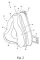
- Figs. 1-2 illustrate an embodiment of a patient interface 100 that is structured to deliver breathable gas to a patient.
- the patient interface 100 includes a frame 12 and a cushion 14 that may be permanently or removably connected to the frame 12.
- a forehead support may be movably mounted to an upper portion 16 of the frame 12.
- a headgear assembly (not shown) can be removably attached to the frame 12 to maintain the frame 12 and cushion 14 in a desired position on the patient's face.
- a swivel elbow assembly 18 is attached to a front portion of the frame 12.
- the elbow assembly 18 is structured to be connected to a conduit that is connected to a pressurized supply of breathable gas.
- a reinforcing member 20 constructed according to an embodiment of the present invention is provided on the cushion 14. As discussed below, the reinforcing member 20 is structured to limit blowout or lateral expansion of the cushion 14 when subject to high pressures during use.
- the patient interface 100 is a full-face mask structured to deliver breathable gas to a patient's nose and mouth.
- the patient interface 100 may be a nasal mask, an oro-nasal mask, a mouth mask, nasal prongs, etc.
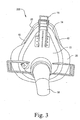
- Figs. 3-5 illustrate another embodiment of a patient interface 200 with a reinforcing member 20 attached thereto
- Figs. 6-8 illustrate another embodiment of a cushion 14 with a reinforcing member 20 attached thereto. Similar elements are indicated with similar reference numerals in the figures. These embodiments primarily differ in the configuration of the gusset portion 26 of the cushion 14, although it should be noted that the reinforcing member 20 also has application to masks not including gussets.
- the cushion 14 includes a non-face-contacting portion 22 structured to be connected to the frame 12, e.g., via a tongue- and-groove arrangement, a face-contacting portion 24 structured to engage a patient's face, and a gusset portion 26 that interconnects the non-face contacting portion 22 and the face-contacting portion 24.
- a preferred face-contacting portion 24 of the cushion 14 includes a side wall 28, an underlying cushion 30 extending away from the side wall 28, and a membrane 32 provided to substantially cover at least a portion of the underlying cushion 30, e.g., see U.S. Patent No. 6,112,746 of Kwok et al. and U.S. Patent Application No. 10/390,68 .
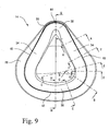
- the face-contacting portion 24 of the cushion 14 preferably has a generally triangular shape and is structured to contact the nasal bridge, cheek, and lower lip region of the patient.
- the face-contacting portion 24 may have any other suitable shape, e.g., a generally trapezoidal shape.
- the cushion 14 includes a pair of cheek regions 34 to provide a seal along the cheeks and the sides of the mouth, a lower lip region 36 to provide a seal below the lower lip of the patient, and a nasal bridge region 38.
- the gusset portion 26 extends radially outwardly with respect to the non-face-contacting and face-contacting portions 22, 24, which allows the face-contacting portion 24 to move relative thereto.
- the gusset portion 26 also increases the sealing efficiency of the cushion 14. Further details of gusset portions 26 are disclosed in U.S. Patent Application No. 10/655,622 and U.S. Patent No. 6,772,760 .
- the gusset portion 26 may be provided in only selected regions of the face, and not others. It need not be provided along the entire perimeter of the cushion 14. Also, the width of the gusset portion 26 may vary along the perimeter of the cushion 14. For example, Figs. 1 and 2 illustrate an embodiment wherein the width of the gusset portion 26 is substantially constant along the perimeter of the cushion 14, whereas Figs. 3-5 and 9 illustrate embodiment wherein the width of the gusset portion 26 is wider in selected regions of the cushion 14, e.g., cheek, lower lip.
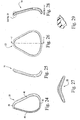
- Figs. 24-29 illustrate an embodiment of the reinforcing member 20 removed from the cushion 14, in isolation.
- the reinforcing member 20 has a ring-like structure and has a shape, e.g., generally triangular, which corresponds with the shape of the cushion 14.
- the reinforcing member 20 includes a pair of cheek regions 40, a lower lip region 42, and a nasal bridge region 44. In its operative position, the reinforcing member 20 engages the cushion 14 along the side wall 28 between the face-contacting portion 24 and the gusset portion 26, e.g., see Figs. 10-17 .
- the reinforcing member 20 has a stiffness that may be selectively varied along its length. As shown in Figs. 9-17 , the width, depth, or transverse cross-sectional size of the reinforcing member 20 may vary along its length or perimeter to modify the stiffness or flexibility of the cushion 14 in certain regions and/or to accommodate for the relative size of the portion of the cushion 14 to be supported. That is, the reinforcing member 20 may be wider in some regions and thinner in other regions. Moreover, the variation of the width of the reinforcing member 20 may correspond with the variation of the width of the gusset portion 26 and/or the side wall 28 along its perimeter.
- the reinforcing member 20 is thinner in the nasal bridge region 44 and lower lip regions 42 (as best shown in Figs. 10, 16, and 17 ), and the reinforcing member 20 is wider in the cheek regions 40 (as best shown in Figs. 11-15 ).
- the reinforcing member 20 is wider at the cheek regions 34 of the cushion 14 to provide more stiffness/reinforcement to the cushion 14 in this region where blowout is more likely to occur, and the reinforcing member 20 is thinner in the nasal bridge and lower lip regions 38, 36 of the cushion 14 to provide less stiffness/reinforcement to the cushion 14 where blowout is less likely to occur.
- the width of reinforcing manner 20 may be varied around its perimeter in any suitable manner.
- the reinforcing member 20 may have a substantially constant width, height, or cross-sectional profile around its perimeter.
- the reinforcing member 20 may be suitably structured such that it can be used with different embodiments and sizes of patient interfaces. Further, the reinforcing member 20 may be suitably structured based on particular needs of a patient. For example, the size of the reinforcing member 20 may be suitably varied based on the treatment pressure that the patient typically experiences.
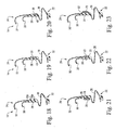
- Figs. 18-23 illustrate various embodiments of attaching the reinforcing member 20 to the,cushion 14.
- Fig. 18 illustrates an embodiment of a pair of spaced apart reinforcing members 20a, 20b attached, e.g., by friction fit, to an exterior surface of the side wall 28 of the cushion 14.
- Fig. 19 illustrates an embodiment of a reinforcing member 20 that is received within a channel 46 provided around at least a portion of the exterior surface of the side wall 28 of the cushion 14.
- Fig. 20 illustrates an embodiment of a reinforcing member 20 having a stepped cross-section configuration around at least a portion thereof that is received within a complementary shaped groove 48 provided around at least a portion of the exterior surface of the side wall 28 of the cushion 14.
- Fig. 21 illustrates an embodiment of a reinforcing member 20 that is received within a channel 46 provided around at least a portion of the interior surface of the side wall 28 of the cushion 14.
- Fig. 22 illustrates an embodiment of a reinforcing member 20 that is attached to the exterior surface of the side wall 28 of the cushion 14 by mechanical fasteners 50, e.g., screws.
- Fig. 23 illustrates an embodiment of a reinforcing member 20 that is attached to the exterior surface of the side wall 28 of the cushion 14 by an adhesive 52, e.g., glue or ultrasonic welding or the like.
- an adhesive 52 e.g., glue or ultrasonic welding or the like.
- the reinforcing member 20 may have a curved or arcuate-shaped transverse cross-sectional configuration.
- the cushion 14 may have a complementary shaped recess adapted to receive the curved reinforcing member 20 therein with an interference fit.
- the reinforcing member 20 may be secured to the cushion 14 in any other suitable manner. Moreover, the reinforcing member 20 may be secured using combinations of the attaching embodiments described above.
- the reinforcing member 20 may include a gap 54 in the nasal bridge region 44.
- the gap 54 may be provided to allow for more movement/flexibility in the nasal bridge region 44, or to facilitate assembly of the reinforcing member 20 to the cushion 14.
- a coordinate system is defined with respect to the facial profile of a patient.
- the x-axis is horizontal
- the y-axis is vertical
- the z-axis is into the plane of the patient's face.
- the reinforcing member 20 adds stiffness to the cushion 14 in the x-y plane to limit lateral expansion of the cushion 14, referred to as blowout, when subject to high pressures.
- the reinforcing member 20 also adds stiffness to the cushion 14 in the y-z plane.
- the reinforcing member 20 links the top and bottom of the cushion 14 which limits independent movement of the top and bottom of the cushion 14 towards and away from the patient's face, i.e., along the z-axis.
- the reinforcing member 20 helps the cushion move in a more uniform manner along the z-axis.
- the reinforcing member 20 provides both lateral support and z-axis support to improve the stability of the cushion 14.
- the reinforcing member 20 may beneficially add mass to the cushion 14 which may improve stability by allowing the cushion 14 to slowly adapt to changes in pressure. That is, the added mass of the reinforcing member 20 may slow the movement of the cushion 14 as it extends and retracts away and towards the patient's face during use.
- the reinforcing member 20 is formed separately from the cushion 14 and attached thereto.
- the reinforcing member 20 may be constructed of a suitable substantially rigid material, e.g., plastic, composite, etc.
- the reinforcing member 20 may be overmolded onto the cushion 14 to form an integral structure.
- the reinforcing member 20 may be embedded along at least a portion of the perimeter of the cushion 14.
- the reinforcing member 20 may be constructed from a thickened bead of silicone that is molded with the cushion 14 as disclosed in U.S. Patent Appln. No. 10/655,622, filed September 5, 2003 .
- the reinforcing member 20 is rigid relative to the cushion 14 under pressure.
- ribs and/or additional thickness may be added to the side wall 28 of the cushion 14 in lieu of the reinforcing member 20.
- the ribs and/or thickness would perform the same function of stiffening the side wall 28 of the cushion 14 to prevent blowout.
- the ribs and/or additional thickness may be utilized in combination with the reinforcing member 20.
- a spring, screw thread, or clipping arrangement may be incorporated into the reinforcing member 20 to allow the reinforcing member 20 to be resized according to the cushion size or pressure range for which it will be used.
- Figs. 30-82 illustrate alternative embodiments of reinforcing members.
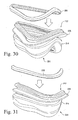
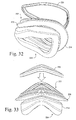
- Figs. 30-38 illustrate another embodiment of a reinforcing member 220 (also referred to as a cushion overclip or saddle overclip) provided to a cushion 214.
- the cushion 214 includes a non-face-contacting portion 222, a face-contacting portion 224, and a gusset portion 226 that interconnects the non-face contacting portion 222 and the face-contacting portion 224.
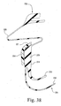
- the face-contacting portion 224 of the cushion 214 includes a side wall 228, an underlying cushion 230, and a membrane 232 (see Fig. 38 ).
- the reinforcing member 220 assembles to the cushion 214 from the top, e.g., over the non-face-contacting portion 222.
- the reinforcing member 220 includes a flange 221 that assists with positioning and retention on the cushion 214 (see Fig. 38 ).
- the reinforcing member 220 engages the cushion 214 along the side wall 228 between the face-contacting portion 224 and the gusset portion 226, e.g., see Figs. 34-38 .
- the reinforcing member 220 may be glued, mechanically fastened, or overmolded in position. However, the reinforcing member 220 may be removable.
- Figs. 39-47 illustrate another embodiment of a reinforcing member 320 (also referred to as a cushion overclip or saddle overclip) provided to a cushion 314.
- the cushion 314 includes a non-face-contacting portion 322, a face-contacting portion 324, and a gusset portion 326 that interconnects the non-face contacting portion 322 and the face-contacting portion 324.
- the face-contacting portion 324 of the cushion 314 includes a side wall 328, an underlying cushion 330, and a membrane 332 (see Fig. 47 ).
- the reinforcing member 320 may be assembled to the cushion 314 from the top, e.g., over the non-face-contacting portion 322, or from the bottom, e.g., over the face-contacting portion 324 ( Figs. 39-42 illustrate assembly from the top).
- the side wall 328 of the cushion 314 includes mushroom head tabs 329 integrally molded therewith.
- the tabs 329 are provided at two positions, i.e., opposing ends of the cushion 314. However, multiple positions are possible. The tabs 329 hold the reinforcing member 320 in its operative position.
- the reinforcing member 320 includes openings 323, e.g., two openings, that receive respective tabs 329 therethrough.
- the tabs 329 may be pushed and/or pulled through respective openings 323 to secure the reinforcing member 320 in position.
- the cushion 314 includes a flange 331 integrally molded therewith that assists with positioning and retention of the reinforcing member 320.
- the reinforcing member 320 engages the cushion 314 along the side wall 328 between the face-contacting portion 324 and the gusset portion 326, e.g., see Figs. 43-47 .
- the reinforcing member 320 may also be glued or overmolded in position. However, the reinforcing member 320 may be removable.
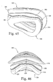
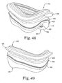
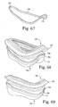
- Figs. 48-49 illustrate another embodiment of a reinforcing member 420 provided to a cushion 414.
- the cushion 414 includes a non-face-contacting portion 422, a face-contacting portion 424, and a gusset portion 426 that interconnects the non-face contacting portion 422 and the face-contacting portion 424.
- the face-contacting portion 424 of the cushion 414 includes a side wall 428, an underlying cushion 430, and a membrane 432.
- the reinforcing member 420 is in the form of a thickened reinforcing section or rib (e.g., a thickened bead of silicone) that is integrally molded with the side wall 428 of the cushion 414.
- the cushion 414 includes one rib 420 that extends horizontally around the cushion perimeter.
- multiple horizontal ribs 420 are possible.
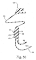
- Fig. 50 illustrates a cushion 414 including three horizontal ribs 420.
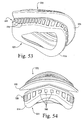
- Figs. 51-56 illustrate another embodiment of a reinforcing member 520 provided to a cushion 514.
- the cushion 514 includes a non-face-contacting portion 522, a face-contacting portion 524, and a gusset portion 526 that interconnects the non-face contacting portion 522 and the face-contacting portion 524.
- the face-contacting portion 524 of the cushion 514 includes a side wall 528, an underlying cushion 530, and a membrane 532 (see Fig. 56 ).
- the reinforcing member 520 is in the form of multiple thickened reinforcing sections or ribs 560 (e.g., thickened beads of silicone) that are integrally molded with the side wall 528 of the cushion 514. As illustrated, each rib 560 extends vertically. The ribs 560 are spaced apart from one another and extend around the cushion perimeter to define the reinforcing member 520.
- ribs 560 e.g., thickened beads of silicone
- the horizontal and vertical ribs 420, 560 are provided on an external surface of the cushion.
- the ribs 420, 560 may be provided on an internal surface of the cushion.
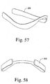
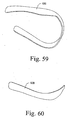
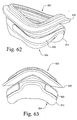
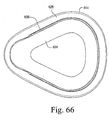
- Figs. 57-66 illustrate another embodiment of a reinforcing member 620 (also referred to as a cushion overclip or saddle overclip) provided to a cushion 614.
- the cushion 614 includes a non-face-contacting portion 622, a face-contacting portion 624, and a gusset portion 626 that interconnects the non-face contacting portion 622 and the face-contacting portion 624.
- the reinforcing member 620 is in the form of a partial cushion overclip that provides reinforcement to selected regions of the cushion 614.
- the reinforcing member 620 is generally U-shaped and includes a cut-out at a nasal bridge area so that the reinforcing member 620 does not provide support in a nasal bridge area of the cushion 614 in use (depending on gusset type). This arrangement also prevents possible interference of the reinforcing member 620 with the patient's nose in use.
- the reinforcing member 620 engages the cushion 614 along a portion of the side wall between the face-contacting portion 624 and the gusset portion 626, e.g., see Figs. 62-66 .
- the reinforcing member 620 may be glued, mechanically fastened, or overmolded in position.
- the reinforcing member 620 is not limited to the design shown in Figs. 57-66 .
- the reinforcing member 620 may include two or more separate pieces, and the cut-out area provided by the reinforcing member 620 may be located in other areas.
- the reinforcing member 620 is provided to a portion of an external surface of the side wall of the cushion 614, e.g., to prevent the cushion from over-inflating or billowing out.
- the reinforcing member 620 may be provided to an internal surface of the cushion.
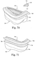
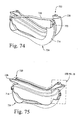
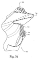
- Figs. 67-76 illustrate another embodiment of a reinforcing member 720 (also referred to as a cushion overclip or saddle overclip) provided to a cushion 714.
- the cushion 714 includes a non-face-contacting portion 722, a face-contacting portion 724, and a gusset portion 726 that interconnects the non-face contacting portion 722 and the face-contacting portion 724.
- the reinforcing member 720 is encapsulated in silicone to secure it onto the cushion 714. Specifically, the reinforcing member 720 is first molded separately from the cushion 714 from a substantially rigid plastic material (see Fig. 67 ). Then, the reinforcing member 720 is mechanically engaged with the cushion 714, i.e., not chemically bonded.
- the rigid plastic cushion overclip 720 is inserted into a tool, and the flexible silicone cushion 714 is molded over the overclip 720, i.e., insert molding.
- the flexible silicone cushion 714 is molded separately from the overclip 720, and the overclip 720 is manually assembled onto the cushion 714.
- the side wall of the cushion 714 includes bosses 729 integrally molded therewith.
- the bosses 729 are provided at two positions, e.g., opposing ends of the cushion 714.
- the bosses 729 assist with locating the overclip 720 in position.
- the overclip 720 includes openings 723, e.g., two openings, that receive respective bosses 729 therethrough.
- a second layer of silicone 770 is locally molded over the overclip/cushion subassembly to encapsulate or encase the overclip 720 (see Figs. 72-76 ). That is, the second layer of silicone 770 bonds to the cushion 714 (also referred to as a first layer of silicone), but does not bond to the overclip 720. This results in the overclip 720 being totally encapsulated or encased in silicone, therefore no openings are provided through which dirt or other debris can enter into the cavity where the overclip 720 is located.
- the reinforcing member 720 is supported on the cushion 714 along a portion of the side wall between the face-contacting portion 724 and the gusset portion 726, e.g., see Figs. 74-76 .
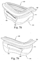
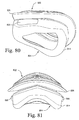
- Figs. 77-82 illustrate another embodiment of a reinforcing member 820 provided to a cushion 814.
- the cushion 814 includes a non-face-contacting portion 822, a face-contacting portion 824, and a gusset portion 826 that interconnects the non-face contacting portion 822 and the face-contacting portion 824.
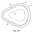
- the reinforcing member 820 is in the form of removable rigid plastic inserts 880 that provide reinforcement to selected regions of the cushion 814.
- the reinforcing member 820 includes two inserts 880 that are removably received within respective pockets 890 integrally molded with the cushion 814. However, more than two positions are possible.
- the inserts 880 engage the cushion 814 along a portion of the side wall between the face-contacting portion 824 and the gusset portion 826.
- the inserts 880 are provided to a portion of an external surface of the side wall of the cushion 814 to act as cushion/gusset stiffening elements to prevent the cushion from over-inflating or billowing out.
- the inserts 880 may be provided to an internal surface of the cushion 814.
- the illustrated embodiments illustrate a reinforcing member being utilized with a cushion including a gusset portion, it should be understood that the reinforcing member may be adapted for use with a cushion without a gusset portion.
- the illustrated embodiments illustrate a reinforcing member being utilized with a full-face mask
- the reinforcing member may be adapted for use with other suitable masks, e.g., nasal masks, etc.
- the reinforcing member is particularly useful with full-face masks because the gusset portion of full-face masks, when compared to nasal masks such as the Activa®, extends further into the breathing cavity (e.g., see Figs. 10-23 ). This arrangement may be perceived as more susceptible to blowout, and hence the incorporation of the reinforcing member into the full face mask limits or eliminates this blowout.
Description
- This application claims the benefit of
U.S. Provisional Application No. 60/643,121, filed January 12, 2005 - The present invention relates to a reinforcing member for a patient interface, the patient interface being used in the treatment, e.g., of Sleep Disordered Breathing (SDB) with Non-Invasive Positive Pressure Ventilation (NIPPV).
- Patient interfaces typically include a rigid shell or frame and a soft face-contacting cushion. The cushion spaces the frame away from the patient's face. The frame and cushion define a cavity which receives the patient's nose or nose and mouth. The frame and cushion are held in position on the patient's face by a headgear assembly.
- A known patient interface, commercially sold under the name of Activa® by ResMed Ltd., includes a cushion having a gusset portion. Further details and embodiments of this cushion are disclosed in U.S. Patent
US 2004/118406 A1 . - The gusset portion is positioned between the frame-contacting side and the face-contacting side of the cushion. In one embodiment described in the application, a reinforcing ring is provided between the gusset portion and the face-contacting side. The reinforcing ring acts as a stiffening hoop reducing the tendency of the cushion to expand at that point when under pressure. In one form, the reinforcing ring is made from polycarbonate and is overmolded or push-fit.
- A need in the art has developed to provide improvements to the above-described reinforcing ring to limit expansion of the cushion when under pressure.
- The patient interface according to the invention is defined in claim 1.
- The invention is to provide a patient interface having a reinforcing member that at least limits lateral expansion of the cushion in use.
- The invention is to provide a patient interface having a reinforcing member that varies a level of reinforcement being provided to selected regions of the cushion.
- The invention relates to a patient interface that includes a frame, a cushion, and a reinforcing member. The cushion has a non-face-contacting portion connected to the frame and a face-contacting portion adapted to engage the patient's face in use. The face-contacting portion includes a side wall and a flexible membrane extending from the side wall. The reinforcing member is provided to at least a portion of an interior and/or exterior surface of the side wall of the cushion. The reinforcing member provides reinforcement to the side wall of the cushion to at least limit lateral expansion of the cushion in use. The reinforcing member has a stiffness that is selectively varied along its length.
- Yet another aspect of the invention relates to a patient interface including a frame, a cushion, and a reinforcing member. The cushion has a non-face-contacting portion connected to the frame and a face-contacting portion adapted to engage the patient's face in use. The face-contacting portion includes a side wall and a flexible membrane extending from the side wall. The reinforcing member is provided to at least a portion of an interior and/or exterior surface of the side wall of the cushion. The reinforcing member provides reinforcement to the side wall of the cushion to at least limit lateral expansion of the cushion in use. The reinforcing member includes at least one reinforcing rib integrally molded with the side wall of the cushion.
- Other aspects, features, and advantages of this invention will become apparent from the following detailed description when taken in conjunction with the accompanying drawings, which are a part of this disclosure and which illustrate, by way of example, principles of this invention.
- The accompanying drawings facilitate an understanding of the various embodiments of this invention. In such drawings:
-
Figs. 1-2 illustrate a patient interface including a reinforcing member; -
Figs. 3-5 illustrate a patient interface including a reinforcing member; -
Figs. 6-8 illustrate a cushion of a patient interface including a reinforcing; -
Figs. 9-17 are cross-sectional views through a cushion having a reinforcing member; -
Figs. 18-23 are cross-sectional views illustrating the attaching of a reinforcing member to a cushion; -
Figs. 24-29 are isolated views of a reinforcing member removed from a cushion; -
Figs. 30-38 illustrate a cushion of a patient interface including a reinforcing member; -
Figs. 39-47 illustrate a cushion of a patient interface including a reinforcing member; -
Fig. 48-49 illustrate a cushion of a patient interface including a reinforcing member; -
Fig. 50 illustrates a cushion of a patient interface including a reinforcing member; -
Figs. 51-56 illustrate a cushion of a patient interface including a reinforcing member; -
Figs. 57-66 illustrate a cushion of a patient interface including a reinforcing member; -
Figs. 67-76 illustrate a cushion of a patient interface including a reinforcing member; and -
Figs. 77-82 illustrate a cushion of a patient interface including a reinforcing member. -
Figs. 1-2 illustrate an embodiment of apatient interface 100 that is structured to deliver breathable gas to a patient. Thepatient interface 100 includes aframe 12 and acushion 14 that may be permanently or removably connected to theframe 12. A forehead support may be movably mounted to anupper portion 16 of theframe 12. A headgear assembly (not shown) can be removably attached to theframe 12 to maintain theframe 12 andcushion 14 in a desired position on the patient's face. Also, aswivel elbow assembly 18 is attached to a front portion of theframe 12. Theelbow assembly 18 is structured to be connected to a conduit that is connected to a pressurized supply of breathable gas. Further, a reinforcingmember 20 constructed according to an embodiment of the present invention is provided on thecushion 14. As discussed below, the reinforcingmember 20 is structured to limit blowout or lateral expansion of thecushion 14 when subject to high pressures during use. - In the illustrated embodiment, the
patient interface 100 is a full-face mask structured to deliver breathable gas to a patient's nose and mouth. However, thepatient interface 100 may be a nasal mask, an oro-nasal mask, a mouth mask, nasal prongs, etc. -
Figs. 3-5 illustrate another embodiment of apatient interface 200 with a reinforcingmember 20 attached thereto, andFigs. 6-8 illustrate another embodiment of acushion 14 with a reinforcingmember 20 attached thereto. Similar elements are indicated with similar reference numerals in the figures. These embodiments primarily differ in the configuration of thegusset portion 26 of thecushion 14, although it should be noted that the reinforcingmember 20 also has application to masks not including gussets. - As best shown in
Figs. 9-23 , thecushion 14 includes a non-face-contactingportion 22 structured to be connected to theframe 12, e.g., via a tongue- and-groove arrangement, a face-contactingportion 24 structured to engage a patient's face, and agusset portion 26 that interconnects the non-face contactingportion 22 and the face-contactingportion 24. As illustrated, a preferred face-contactingportion 24 of thecushion 14 includes aside wall 28, anunderlying cushion 30 extending away from theside wall 28, and amembrane 32 provided to substantially cover at least a portion of theunderlying cushion 30, e.g., seeU.S. Patent No. 6,112,746 of Kwok et al. andU.S. Patent Application No. 10/390,68 . - As best shown in
Fig. 9 , the face-contactingportion 24 of thecushion 14 preferably has a generally triangular shape and is structured to contact the nasal bridge, cheek, and lower lip region of the patient. However, the face-contactingportion 24 may have any other suitable shape, e.g., a generally trapezoidal shape. In the illustrated embodiment, thecushion 14 includes a pair ofcheek regions 34 to provide a seal along the cheeks and the sides of the mouth, alower lip region 36 to provide a seal below the lower lip of the patient, and anasal bridge region 38. - The
gusset portion 26 extends radially outwardly with respect to the non-face-contacting and face-contactingportions portion 24 to move relative thereto. Thegusset portion 26 also increases the sealing efficiency of thecushion 14. Further details ofgusset portions 26 are disclosed inU.S. Patent Application No. 10/655,622 andU.S. Patent No. 6,772,760 . - The
gusset portion 26 may be provided in only selected regions of the face, and not others. It need not be provided along the entire perimeter of thecushion 14. Also, the width of thegusset portion 26 may vary along the perimeter of thecushion 14. For example,Figs. 1 and2 illustrate an embodiment wherein the width of thegusset portion 26 is substantially constant along the perimeter of thecushion 14, whereasFigs. 3-5 and9 illustrate embodiment wherein the width of thegusset portion 26 is wider in selected regions of thecushion 14, e.g., cheek, lower lip. -
Figs. 24-29 illustrate an embodiment of the reinforcingmember 20 removed from thecushion 14, in isolation. As illustrated, the reinforcingmember 20 has a ring-like structure and has a shape, e.g., generally triangular, which corresponds with the shape of thecushion 14. The reinforcingmember 20 includes a pair ofcheek regions 40, alower lip region 42, and anasal bridge region 44. In its operative position, the reinforcingmember 20 engages thecushion 14 along theside wall 28 between the face-contactingportion 24 and thegusset portion 26, e.g., seeFigs. 10-17 . - The reinforcing
member 20 has a stiffness that may be selectively varied along its length. As shown inFigs. 9-17 , the width, depth, or transverse cross-sectional size of the reinforcingmember 20 may vary along its length or perimeter to modify the stiffness or flexibility of thecushion 14 in certain regions and/or to accommodate for the relative size of the portion of thecushion 14 to be supported. That is, the reinforcingmember 20 may be wider in some regions and thinner in other regions. Moreover, the variation of the width of the reinforcingmember 20 may correspond with the variation of the width of thegusset portion 26 and/or theside wall 28 along its perimeter. - For example, the reinforcing
member 20 is thinner in thenasal bridge region 44 and lower lip regions 42 (as best shown inFigs. 10, 16, and 17 ), and the reinforcingmember 20 is wider in the cheek regions 40 (as best shown inFigs. 11-15 ). When attached to thecushion 14, the reinforcingmember 20 is wider at thecheek regions 34 of thecushion 14 to provide more stiffness/reinforcement to thecushion 14 in this region where blowout is more likely to occur, and the reinforcingmember 20 is thinner in the nasal bridge andlower lip regions cushion 14 to provide less stiffness/reinforcement to thecushion 14 where blowout is less likely to occur. However, the width of reinforcingmanner 20 may be varied around its perimeter in any suitable manner. Moreover, the reinforcingmember 20 may have a substantially constant width, height, or cross-sectional profile around its perimeter. - Also, the reinforcing
member 20 may be suitably structured such that it can be used with different embodiments and sizes of patient interfaces. Further, the reinforcingmember 20 may be suitably structured based on particular needs of a patient. For example, the size of the reinforcingmember 20 may be suitably varied based on the treatment pressure that the patient typically experiences. -
Figs. 18-23 illustrate various embodiments of attaching the reinforcingmember 20 to the,cushion 14. For example,Fig. 18 illustrates an embodiment of a pair of spaced apart reinforcingmembers side wall 28 of thecushion 14.Fig. 19 illustrates an embodiment of a reinforcingmember 20 that is received within achannel 46 provided around at least a portion of the exterior surface of theside wall 28 of thecushion 14.Fig. 20 illustrates an embodiment of a reinforcingmember 20 having a stepped cross-section configuration around at least a portion thereof that is received within a complementary shapedgroove 48 provided around at least a portion of the exterior surface of theside wall 28 of thecushion 14.Fig. 21 illustrates an embodiment of a reinforcingmember 20 that is received within achannel 46 provided around at least a portion of the interior surface of theside wall 28 of thecushion 14.Fig. 22 illustrates an embodiment of a reinforcingmember 20 that is attached to the exterior surface of theside wall 28 of thecushion 14 bymechanical fasteners 50, e.g., screws.Fig. 23 illustrates an embodiment of a reinforcingmember 20 that is attached to the exterior surface of theside wall 28 of thecushion 14 by an adhesive 52, e.g., glue or ultrasonic welding or the like. - As shown in
Figs. 28 and 29 , the reinforcingmember 20 may have a curved or arcuate-shaped transverse cross-sectional configuration. Thecushion 14 may have a complementary shaped recess adapted to receive the curved reinforcingmember 20 therein with an interference fit. - However, it should be understood that the reinforcing
member 20 may be secured to thecushion 14 in any other suitable manner. Moreover, the reinforcingmember 20 may be secured using combinations of the attaching embodiments described above. - As shown in
Fig. 2 , the reinforcingmember 20 may include agap 54 in thenasal bridge region 44. Thegap 54 may be provided to allow for more movement/flexibility in thenasal bridge region 44, or to facilitate assembly of the reinforcingmember 20 to thecushion 14. - To better understand the advantages of the present invention, a coordinate system is defined with respect to the facial profile of a patient. When a patient is sitting upright, the x-axis is horizontal, the y-axis is vertical, and the z-axis is into the plane of the patient's face. The reinforcing
member 20 adds stiffness to thecushion 14 in the x-y plane to limit lateral expansion of thecushion 14, referred to as blowout, when subject to high pressures. The reinforcingmember 20 also adds stiffness to thecushion 14 in the y-z plane. That is, the reinforcingmember 20 links the top and bottom of thecushion 14 which limits independent movement of the top and bottom of thecushion 14 towards and away from the patient's face, i.e., along the z-axis. The reinforcingmember 20 helps the cushion move in a more uniform manner along the z-axis. Thus, the reinforcingmember 20 provides both lateral support and z-axis support to improve the stability of thecushion 14. - Also, the reinforcing
member 20 may beneficially add mass to thecushion 14 which may improve stability by allowing thecushion 14 to slowly adapt to changes in pressure. That is, the added mass of the reinforcingmember 20 may slow the movement of thecushion 14 as it extends and retracts away and towards the patient's face during use. - In illustrated embodiments, the reinforcing
member 20 is formed separately from thecushion 14 and attached thereto. The reinforcingmember 20 may be constructed of a suitable substantially rigid material, e.g., plastic, composite, etc. However, in other embodiments, the reinforcingmember 20 may be overmolded onto thecushion 14 to form an integral structure. In one example, the reinforcingmember 20 may be embedded along at least a portion of the perimeter of thecushion 14. Also, the reinforcingmember 20 may be constructed from a thickened bead of silicone that is molded with thecushion 14 as disclosed inU.S. Patent Appln. No. 10/655,622, filed September 5, 2003 member 20 is rigid relative to thecushion 14 under pressure. - In another embodiment, ribs and/or additional thickness may be added to the
side wall 28 of thecushion 14 in lieu of the reinforcingmember 20. The ribs and/or thickness would perform the same function of stiffening theside wall 28 of thecushion 14 to prevent blowout. In an alternative embodiment, the ribs and/or additional thickness may be utilized in combination with the reinforcingmember 20. - In another embodiment, a spring, screw thread, or clipping arrangement, for example, may be incorporated into the reinforcing
member 20 to allow the reinforcingmember 20 to be resized according to the cushion size or pressure range for which it will be used. -
Figs. 30-82 illustrate alternative embodiments of reinforcing members. For example,Figs. 30-38 illustrate another embodiment of a reinforcing member 220 (also referred to as a cushion overclip or saddle overclip) provided to acushion 214. As illustrated, thecushion 214 includes a non-face-contactingportion 222, a face-contactingportion 224, and agusset portion 226 that interconnects thenon-face contacting portion 222 and the face-contactingportion 224. The face-contactingportion 224 of thecushion 214 includes aside wall 228, anunderlying cushion 230, and a membrane 232 (seeFig. 38 ). - As shown in
Figs. 30-33 , the reinforcingmember 220 assembles to thecushion 214 from the top, e.g., over the non-face-contactingportion 222. The reinforcingmember 220 includes aflange 221 that assists with positioning and retention on the cushion 214 (seeFig. 38 ). In its operative position, the reinforcingmember 220 engages thecushion 214 along theside wall 228 between the face-contactingportion 224 and thegusset portion 226, e.g., seeFigs. 34-38 . The reinforcingmember 220 may be glued, mechanically fastened, or overmolded in position. However, the reinforcingmember 220 may be removable. -
Figs. 39-47 illustrate another embodiment of a reinforcing member 320 (also referred to as a cushion overclip or saddle overclip) provided to acushion 314. As illustrated, thecushion 314 includes a non-face-contactingportion 322, a face-contactingportion 324, and agusset portion 326 that interconnects thenon-face contacting portion 322 and the face-contactingportion 324. The face-contactingportion 324 of thecushion 314 includes aside wall 328, anunderlying cushion 330, and a membrane 332 (seeFig. 47 ). - The reinforcing
member 320 may be assembled to thecushion 314 from the top, e.g., over the non-face-contactingportion 322, or from the bottom, e.g., over the face-contacting portion 324 (Figs. 39-42 illustrate assembly from the top). As illustrated, theside wall 328 of thecushion 314 includesmushroom head tabs 329 integrally molded therewith. In the illustrated embodiment, thetabs 329 are provided at two positions, i.e., opposing ends of thecushion 314. However, multiple positions are possible. Thetabs 329 hold the reinforcingmember 320 in its operative position. - Specifically, the reinforcing
member 320 includesopenings 323, e.g., two openings, that receiverespective tabs 329 therethrough. Thetabs 329 may be pushed and/or pulled throughrespective openings 323 to secure the reinforcingmember 320 in position. Also, thecushion 314 includes aflange 331 integrally molded therewith that assists with positioning and retention of the reinforcingmember 320. - In its operative position, the reinforcing
member 320 engages thecushion 314 along theside wall 328 between the face-contactingportion 324 and thegusset portion 326, e.g., seeFigs. 43-47 . The reinforcingmember 320 may also be glued or overmolded in position. However, the reinforcingmember 320 may be removable. -
Figs. 48-49 illustrate another embodiment of a reinforcingmember 420 provided to a cushion 414. As illustrated, the cushion 414 includes a non-face-contactingportion 422, a face-contactingportion 424, and agusset portion 426 that interconnects thenon-face contacting portion 422 and the face-contactingportion 424. The face-contactingportion 424 of the cushion 414 includes aside wall 428, anunderlying cushion 430, and amembrane 432. - In the illustrated embodiment, the reinforcing
member 420 is in the form of a thickened reinforcing section or rib (e.g., a thickened bead of silicone) that is integrally molded with theside wall 428 of the cushion 414. As illustrated, the cushion 414 includes onerib 420 that extends horizontally around the cushion perimeter. However, multiplehorizontal ribs 420 are possible. For example,Fig. 50 illustrates a cushion 414 including threehorizontal ribs 420. -
Figs. 51-56 illustrate another embodiment of a reinforcingmember 520 provided to acushion 514. As illustrated, thecushion 514 includes a non-face-contactingportion 522, a face-contactingportion 524, and agusset portion 526 that interconnects thenon-face contacting portion 522 and the face-contactingportion 524. The face-contactingportion 524 of thecushion 514 includes aside wall 528, anunderlying cushion 530, and a membrane 532 (seeFig. 56 ). - In the illustrated embodiment, the reinforcing
member 520 is in the form of multiple thickened reinforcing sections or ribs 560 (e.g., thickened beads of silicone) that are integrally molded with theside wall 528 of thecushion 514. As illustrated, eachrib 560 extends vertically. Theribs 560 are spaced apart from one another and extend around the cushion perimeter to define the reinforcingmember 520. - As shown in
Figs. 48-56 , the horizontal andvertical ribs ribs -
Figs. 57-66 illustrate another embodiment of a reinforcing member 620 (also referred to as a cushion overclip or saddle overclip) provided to acushion 614. As shown inFigs. 62-66 , thecushion 614 includes a non-face-contactingportion 622, a face-contactingportion 624, and agusset portion 626 that interconnects thenon-face contacting portion 622 and the face-contactingportion 624. - In the illustrated embodiment, the reinforcing
member 620 is in the form of a partial cushion overclip that provides reinforcement to selected regions of thecushion 614. Specifically, the reinforcingmember 620 is generally U-shaped and includes a cut-out at a nasal bridge area so that the reinforcingmember 620 does not provide support in a nasal bridge area of thecushion 614 in use (depending on gusset type). This arrangement also prevents possible interference of the reinforcingmember 620 with the patient's nose in use. - In its operative position, the reinforcing
member 620 engages thecushion 614 along a portion of the side wall between the face-contactingportion 624 and thegusset portion 626, e.g., seeFigs. 62-66 . The reinforcingmember 620 may be glued, mechanically fastened, or overmolded in position. - The reinforcing
member 620 is not limited to the design shown inFigs. 57-66 . For example, the reinforcingmember 620 may include two or more separate pieces, and the cut-out area provided by the reinforcingmember 620 may be located in other areas. - Also, in the illustrated embodiment, the reinforcing
member 620 is provided to a portion of an external surface of the side wall of thecushion 614, e.g., to prevent the cushion from over-inflating or billowing out. However, the reinforcingmember 620 may be provided to an internal surface of the cushion. -
Figs. 67-76 illustrate another embodiment of a reinforcing member 720 (also referred to as a cushion overclip or saddle overclip) provided to acushion 714. Thecushion 714 includes a non-face-contactingportion 722, a face-contactingportion 724, and agusset portion 726 that interconnects thenon-face contacting portion 722 and the face-contactingportion 724. - In the illustrated embodiment, the reinforcing
member 720 is encapsulated in silicone to secure it onto thecushion 714. Specifically, the reinforcingmember 720 is first molded separately from thecushion 714 from a substantially rigid plastic material (seeFig. 67 ). Then, the reinforcingmember 720 is mechanically engaged with thecushion 714, i.e., not chemically bonded. - In one embodiment, the rigid
plastic cushion overclip 720 is inserted into a tool, and theflexible silicone cushion 714 is molded over theoverclip 720, i.e., insert molding. - In another embodiment, the
flexible silicone cushion 714 is molded separately from theoverclip 720, and theoverclip 720 is manually assembled onto thecushion 714. For example, as shown inFigs. 68-71 , the side wall of thecushion 714 includesbosses 729 integrally molded therewith. In the illustrated embodiment, thebosses 729 are provided at two positions, e.g., opposing ends of thecushion 714. However, multiple positions are possible. Thebosses 729 assist with locating theoverclip 720 in position. Specifically, theoverclip 720 includesopenings 723, e.g., two openings, that receiverespective bosses 729 therethrough. - After the
overclip 720 is mechanically engaged with thecushion 714 to provide an overclip/cushion subassembly, a second layer ofsilicone 770 is locally molded over the overclip/cushion subassembly to encapsulate or encase the overclip 720 (seeFigs. 72-76 ). That is, the second layer ofsilicone 770 bonds to the cushion 714 (also referred to as a first layer of silicone), but does not bond to theoverclip 720. This results in theoverclip 720 being totally encapsulated or encased in silicone, therefore no openings are provided through which dirt or other debris can enter into the cavity where theoverclip 720 is located. - In its operative position, the reinforcing
member 720 is supported on thecushion 714 along a portion of the side wall between the face-contactingportion 724 and thegusset portion 726, e.g., seeFigs. 74-76 . -
Figs. 77-82 illustrate another embodiment of a reinforcingmember 820 provided to acushion 814. Thecushion 814 includes a non-face-contactingportion 822, a face-contactingportion 824, and agusset portion 826 that interconnects thenon-face contacting portion 822 and the face-contactingportion 824. - In the illustrated embodiment, the reinforcing
member 820 is in the form of removable rigid plastic inserts 880 that provide reinforcement to selected regions of thecushion 814. Specifically, the reinforcingmember 820 includes twoinserts 880 that are removably received withinrespective pockets 890 integrally molded with thecushion 814. However, more than two positions are possible. - In its operative position, the
inserts 880 engage thecushion 814 along a portion of the side wall between the face-contactingportion 824 and thegusset portion 826. Theinserts 880 are provided to a portion of an external surface of the side wall of thecushion 814 to act as cushion/gusset stiffening elements to prevent the cushion from over-inflating or billowing out. However, theinserts 880 may be provided to an internal surface of thecushion 814. - Although the illustrated embodiments illustrate a reinforcing member being utilized with a cushion including a gusset portion, it should be understood that the reinforcing member may be adapted for use with a cushion without a gusset portion.
- Also, although the illustrated embodiments illustrate a reinforcing member being utilized with a full-face mask, it should be understood that the reinforcing member may be adapted for use with other suitable masks, e.g., nasal masks, etc. Specifically, the reinforcing member is particularly useful with full-face masks because the gusset portion of full-face masks, when compared to nasal masks such as the Activa®, extends further into the breathing cavity (e.g., see
Figs. 10-23 ). This arrangement may be perceived as more susceptible to blowout, and hence the incorporation of the reinforcing member into the full face mask limits or eliminates this blowout. - In addition, while the invention has particular application to patients who suffer from OSA, it is to be appreciated that patients who suffer from other illnesses (e.g., congestive heart failure, diabetes, morbid obesity, stroke, barriatric surgery, etc.) can derive benefit from the above teachings. Moreover, the above teachings have applicability with patients and non-patients alike in non-medical applications.
Claims (18)
- A patient interface (100, 200), comprising:a frame (12);a cushion (x14) having a non-face-contacting portion (x22) adapted to be connected to the frame (12) and a face-contacting portion (x24) adapted to engage the patient's face in use, the face-contacting portion (x24) including a side wall (x28) and a flexible membrane (x32) extending from the side wall (x28); anda reinforcing member (x20) provided to at least a portion of an interior and/or exterior surface of the side wall (x28), the reinforcing member (x20) providing reinforcement to the side wall (x28) of the cushion (x14) to at least limit lateral expansion of the cushion (x14) in use,characterized in thatthe reinforcing member (x20) includes a cut-out so that the reinforcing member (x20) provides support to selected regions of the cushion (x14), andthe reinforcing member (x20) is generally U-shaped.
- The patient interface (100, 200) according to claim 1, wherein the reinforcing member (x20) includes at least one reinforcing rib (420, 560) integrally molded with the side wall (x28).
- The patient interface (100, 200) according to claim 2 with multiple reinforcing ribs, wherein the ribs (420, 560) are spaced apart from one another.
- The patient interface (100, 200) according to claim 2 or 3 with multiple reinforcing ribs, wherein the reinforcing ribs (420, 560) extend around at least a portion of a cushion (x 14) perimeter.
- The patient interface (100, 200) according to any of claims 2 to 4 with multiple reinforcing ribs, wherein at least one of the reinforcing ribs (420, 560) includes a different length than another one of the ribs (420, 560).
- The cushion (x14) according to any of claims 1 to 5, wherein the face-contacting portion (x24) is structured to sealingly engage around the patient's nose and mouth.
- The patient interface (100, 200) according to any of claims 1 to 7, wherein the reinforcing member (x20) is provided only to one or more selected portions of the cushion (x 14).
- A patient interface (100, 200) according to any one of the preceding claims, wherein the cushion (x14) comprises a gusset portion (x26) that interconnects the non-face-contacting portion (x22) and the face-contacting portion (x24).
- A patient interface (100, 200) according to claim 8, wherein the reinforcing member (x20) is positioned between the face-contacting portion (x24) and the gusset portion (x26).
- A patient interface (100, 200) according to claims 8 or 9, wherein the gusset portion (x26) extends radially outward with respect to the non-face-contacting (x22) and face contacting-portions (x24).
- A patient interface (100, 200) according to any of claims 8 to 10, wherein the gusset portion (x26) is only provided along selected regions of the perimeter of the cushion (x14).
- A patient interface (100, 200) according to any of the preceding claims 8 to 11, wherein the width of the gusset portion (x26) varies along the perimeter of the cushion (x14).
- A patient interface (100, 200) according to any of the preceding claims, wherein the transverse cross-sectional size of the reinforcing member (x20) varies along its length.
- A patient interface (100, 200) according to any of the claims 1 to 12, wherein the reinforcing member (20) has a substantially constant cross-sectional profile around its perimeter.
- A patient interface (100, 200) according to any of the claims 1 to 13, wherein the reinforcing member (x20) is thinner in a nasal bridge region (44) than in a cheek region (40).
- A patient interface (100, 200) according to any of the preceding claims, wherein the reinforcing member (x20) has a curved transverse cross-sectional configuration.
- A patient interface (100, 200) according to any of the preceding claims, wherein the cushion (x14) and the reinforcing member (x20) form an integral component.
- A patient interface (100, 200) according to any of the preceding claims, wherein the reinforcing member (x20) is a thickened bead of silicone molded with the cushion (x14).
Priority Applications (1)
| Application Number | Priority Date | Filing Date | Title |
|---|---|---|---|
| EP16177950.9A EP3103499B1 (en) | 2005-01-12 | 2006-01-12 | Reinforcing member for a patient interface |
Applications Claiming Priority (2)
| Application Number | Priority Date | Filing Date | Title |
|---|---|---|---|
| US64312105P | 2005-01-12 | 2005-01-12 | |
| PCT/AU2006/000033 WO2006074514A1 (en) | 2005-01-12 | 2006-01-12 | Reinforcing member for a patient interface |
Related Child Applications (1)
| Application Number | Title | Priority Date | Filing Date |
|---|---|---|---|
| EP16177950.9A Division EP3103499B1 (en) | 2005-01-12 | 2006-01-12 | Reinforcing member for a patient interface |
Publications (3)
| Publication Number | Publication Date |
|---|---|
| EP1841482A1 EP1841482A1 (en) | 2007-10-10 |
| EP1841482A4 EP1841482A4 (en) | 2009-11-11 |
| EP1841482B1 true EP1841482B1 (en) | 2016-07-06 |
Family
ID=36677305
Family Applications (2)
| Application Number | Title | Priority Date | Filing Date |
|---|---|---|---|
| EP16177950.9A Active EP3103499B1 (en) | 2005-01-12 | 2006-01-12 | Reinforcing member for a patient interface |
| EP06704769.6A Revoked EP1841482B1 (en) | 2005-01-12 | 2006-01-12 | Reinforcing member for a patient interface |
Family Applications Before (1)
| Application Number | Title | Priority Date | Filing Date |
|---|---|---|---|
| EP16177950.9A Active EP3103499B1 (en) | 2005-01-12 | 2006-01-12 | Reinforcing member for a patient interface |
Country Status (7)
| Country | Link |
|---|---|
| US (3) | US8261746B2 (en) |
| EP (2) | EP3103499B1 (en) |
| JP (1) | JP5160236B2 (en) |
| CN (2) | CN100574825C (en) |
| AU (1) | AU2006206041A1 (en) |
| NZ (1) | NZ556251A (en) |
| WO (1) | WO2006074514A1 (en) |
Families Citing this family (97)
| Publication number | Priority date | Publication date | Assignee | Title |
|---|---|---|---|---|
| US7442629B2 (en) | 2004-09-24 | 2008-10-28 | President & Fellows Of Harvard College | Femtosecond laser-induced formation of submicrometer spikes on a semiconductor substrate |
| US7057256B2 (en) | 2001-05-25 | 2006-06-06 | President & Fellows Of Harvard College | Silicon-based visible and near-infrared optoelectric devices |
| EP2514471B1 (en) | 2003-05-02 | 2016-01-13 | ResMed Ltd. | A mask system |
| ES2381478T3 (en) | 2003-12-08 | 2012-05-28 | Fisher & Paykel Healthcare Limited | Respiratory aid |
| US8783257B2 (en) | 2004-02-23 | 2014-07-22 | Fisher & Paykel Healthcare Limited | Breathing assistance apparatus |
| AU2005228827C1 (en) | 2004-04-02 | 2022-02-03 | Fisher & Paykel Healthcare Limited | Breathing assistance apparatus |
| US9072852B2 (en) | 2004-04-02 | 2015-07-07 | Fisher & Paykel Healthcare Limited | Breathing assistance apparatus |
| NZ556198A (en) | 2005-01-12 | 2010-10-29 | Resmed Ltd | Cushion for patient interface |
| JP5160236B2 (en) | 2005-01-12 | 2013-03-13 | レスメド・リミテッド | Cushion for patient interface and patient interface |
| US20090151729A1 (en) | 2005-11-08 | 2009-06-18 | Resmed Limited | Nasal Assembly |
| US7762258B2 (en) | 2005-12-02 | 2010-07-27 | Carefusion 2200, Inc. | Infant nasal interface mask |
| WO2007145534A1 (en) * | 2006-06-16 | 2007-12-21 | Fisher & Paykel Healthcare Limited | Breathing assistance apparatus |
| DE202007019687U1 (en) | 2006-07-14 | 2015-07-14 | Fisher & Paykel Healthcare Ltd. | Respiratory support device |
| WO2008058330A1 (en) | 2006-11-14 | 2008-05-22 | Resmed Ltd | Frame and vent assembly for mask assembly |
| JP4945432B2 (en) | 2006-12-28 | 2012-06-06 | 富士フイルム株式会社 | Preparation method of lithographic printing plate |
| NZ567460A (en) * | 2007-04-19 | 2010-02-26 | Resmed Ltd | Cushion and cushion to frame assembly mechanism for patient interface |
| NZ772129A (en) | 2008-03-04 | 2022-10-28 | ResMed Pty Ltd | Mask system |
| US11331447B2 (en) | 2008-03-04 | 2022-05-17 | ResMed Pty Ltd | Mask system with snap-fit shroud |
| AU2014100362B4 (en) * | 2008-03-04 | 2014-08-14 | Resmed Limited | Mask System |
| US8066738B2 (en) * | 2008-03-31 | 2011-11-29 | Playtex Products, Inc. | Pacifier |
| US10792451B2 (en) | 2008-05-12 | 2020-10-06 | Fisher & Paykel Healthcare Limited | Patient interface and aspects thereof |
| US10258757B2 (en) | 2008-05-12 | 2019-04-16 | Fisher & Paykel Healthcare Limited | Patient interface and aspects thereof |
| EP2145645B1 (en) * | 2008-07-18 | 2012-01-04 | Fisher & Paykel Healthcare Limited | Breathing assistance apparatus |
| US11660413B2 (en) | 2008-07-18 | 2023-05-30 | Fisher & Paykel Healthcare Limited | Breathing assistance apparatus |
| WO2010041966A1 (en) | 2008-10-10 | 2010-04-15 | Fisher & Paykel Healthcare Limited | Nasal pillows for a patient interface |
| CN104623785B (en) * | 2008-12-17 | 2017-05-10 | 菲舍尔和佩克尔保健有限公司 | Respiratory mask sealing interface |
| US9673243B2 (en) | 2009-09-17 | 2017-06-06 | Sionyx, Llc | Photosensitive imaging devices and associated methods |
| US9911781B2 (en) | 2009-09-17 | 2018-03-06 | Sionyx, Llc | Photosensitive imaging devices and associated methods |
| WO2011062510A1 (en) | 2009-11-18 | 2011-05-26 | Fisher & Paykel Healthcare Limited | Nasal interface |
| CN115591073A (en) | 2009-11-20 | 2023-01-13 | 瑞思迈私人有限公司(Au) | Mask system |
| US8692198B2 (en) | 2010-04-21 | 2014-04-08 | Sionyx, Inc. | Photosensitive imaging devices and associated methods |
| CN106449684B (en) | 2010-06-18 | 2019-09-27 | 西奥尼克斯公司 | High speed photosensitive device and correlation technique |
| EP4070841A1 (en) | 2010-10-08 | 2022-10-12 | Fisher & Paykel Healthcare Limited | Breathing assistance apparatus |
| US10603456B2 (en) | 2011-04-15 | 2020-03-31 | Fisher & Paykel Healthcare Limited | Interface comprising a nasal sealing portion |
| EP4282456A3 (en) | 2011-04-15 | 2024-02-14 | Fisher & Paykel Healthcare Limited | Interface comprising a rolling nasal bridge portion |
| US9496308B2 (en) | 2011-06-09 | 2016-11-15 | Sionyx, Llc | Process module for increasing the response of backside illuminated photosensitive imagers and associated methods |
| EP3566736B1 (en) * | 2011-07-01 | 2020-12-09 | Fisher & Paykel Healthcare Limited | Nasal mask interface assembly |
| CN103796700B (en) * | 2011-07-12 | 2017-05-24 | 瑞思迈有限公司 | Textile mask systems |
| WO2013010127A2 (en) | 2011-07-13 | 2013-01-17 | Sionyx, Inc. | Biometric imaging devices and associated methods |
| WO2013061260A1 (en) * | 2011-10-26 | 2013-05-02 | Koninklijke Philips Electronics N.V. | Cushion for patient interface with localized region of reduced stiffness |
| RU2014131076A (en) * | 2011-12-27 | 2016-02-20 | Конинклейке Филипс Н.В. | PATIENT INTERFACE, ITS LAYING, AND ALSO METHOD OF MANUFACTURE |
| US9064764B2 (en) | 2012-03-22 | 2015-06-23 | Sionyx, Inc. | Pixel isolation elements, devices, and associated methods |
| EP2849829B1 (en) * | 2012-05-16 | 2018-11-21 | Koninklijke Philips N.V. | Patient interface devices |
| EP2858704B1 (en) * | 2012-06-12 | 2016-11-09 | Koninklijke Philips N.V. | Sealing cushion having corrugated sealing flap cross-reference to related applications |
| US10232135B2 (en) | 2012-08-03 | 2019-03-19 | Fisher & Paykel Healthcare Limited | Deformable insert for low pressure patient interface |
| GB2519261B (en) | 2012-08-08 | 2018-02-28 | Fisher & Paykel Healthcare Ltd | Headgear for patient interface |
| EP4279106A3 (en) | 2012-09-04 | 2024-01-17 | Fisher & Paykel Healthcare Limited | Valsalva mask |
| GB2522582B (en) | 2012-11-16 | 2019-09-04 | Fisher & Paykel Healthcare Ltd | Nasal seal and respiratory interface |
| WO2014091360A1 (en) * | 2012-12-13 | 2014-06-19 | Koninklijke Philips N.V. | Mask with red mark alleviating pocket |
| WO2017049361A1 (en) * | 2015-09-23 | 2017-03-30 | Resmed Limited | Patient interface with a seal-forming structure having varying thickness |
| US9762830B2 (en) | 2013-02-15 | 2017-09-12 | Sionyx, Llc | High dynamic range CMOS image sensor having anti-blooming properties and associated methods |
| US9939251B2 (en) | 2013-03-15 | 2018-04-10 | Sionyx, Llc | Three dimensional imaging utilizing stacked imager devices and associated methods |
| US9209345B2 (en) | 2013-06-29 | 2015-12-08 | Sionyx, Inc. | Shallow trench textured regions and associated methods |
| EP3021922B1 (en) | 2013-07-17 | 2020-09-02 | Fisher & Paykel Healthcare Limited | Patient interface and aspects thereof |
| DE112014003604T5 (en) | 2013-08-05 | 2016-06-02 | Fisher & Paykel Healthcare Limited | Seal for a patient interface, junction assemblies, and aspects thereof |
| GB201314884D0 (en) * | 2013-08-20 | 2013-10-02 | 3M Innovative Properties Co | Personal respiratory protection device |
| GB201314885D0 (en) * | 2013-08-20 | 2013-10-02 | 3M Innovative Properties Co | Personal respiratory protection device |
| GB201314886D0 (en) * | 2013-08-20 | 2013-10-02 | 3M Innovative Properties Co | Personal respiratory protection device |
| USD740932S1 (en) * | 2013-09-24 | 2015-10-13 | 3M Innovative Properties Company | Respirator with raised face seal flexing region |
| USD787659S1 (en) * | 2013-09-24 | 2017-05-23 | 3M Innovative Properties Company | Respirator with face seal flexing region |
| ITPG20130052A1 (en) * | 2013-11-12 | 2015-05-13 | 3A Health Care S R L | MASK FOR THE ADMINISTRATION OF AN ATOMIZED MIXTURE |
| GB2521644B (en) | 2013-12-24 | 2020-03-11 | Intersurgical Ag | Improvements relating to respiratory masks |
| CN103830820A (en) * | 2014-03-14 | 2014-06-04 | 宁波圣宇瑞医疗器械有限公司 | Medical face mask and face mask assembly |
| CN103816600A (en) * | 2014-03-14 | 2014-05-28 | 宁波圣宇瑞医疗器械有限公司 | Medical mask |
| EP3808397B1 (en) * | 2014-03-18 | 2024-04-24 | Fisher & Paykel Healthcare Limited | Gel resuscitation mask |
| EP3689183A1 (en) | 2014-06-04 | 2020-08-05 | Revolutionary Medical Devices, Inc. | Combined nasal and mouth ventilation mask |
| SG11201608616VA (en) | 2014-06-17 | 2017-01-27 | Fisher & Paykel Healthcare Ltd | Patient interfaces |
| US20150374943A1 (en) * | 2014-06-30 | 2015-12-31 | Alex Alexani | Flexible cushion system for oxygen mask |
| US10518057B2 (en) * | 2014-07-16 | 2019-12-31 | Human Design Medical, Llc | Facial interface and headgear system for use with ventilation and positive air pressure systems |
| SG11201701253UA (en) | 2014-08-20 | 2017-03-30 | Revolutionary Medical Devices Inc | Ventilation mask |
| GB2544428B (en) | 2014-08-25 | 2021-03-24 | Fisher & Paykel Healthcare Ltd | A cushion module for a respiratory interface |
| USD825740S1 (en) | 2014-12-12 | 2018-08-14 | Revolutionary Medical Devices | Surgical mask |
| EP4268873A3 (en) * | 2015-03-27 | 2024-02-14 | Fisher & Paykel Healthcare Limited | Patient interface and aspects thereof |
| CA3198582A1 (en) | 2015-06-11 | 2016-12-15 | Revolutionary Medical Devices, Inc. | Ventilation mask |
| EP3344318B1 (en) | 2015-09-04 | 2021-11-03 | Fisher & Paykel Healthcare Limited | Patient interfaces |
| CN105413035A (en) * | 2015-12-24 | 2016-03-23 | 北京怡和嘉业医疗科技有限公司 | Liner for breathing mask and breathing mask |
| CN108452420B (en) * | 2016-04-13 | 2020-06-23 | 莫言帅 | Face mask |
| USD882066S1 (en) | 2016-05-13 | 2020-04-21 | Fisher & Paykel Healthcare Limited | Frame for a breathing mask |
| CN106267489B (en) * | 2016-08-25 | 2018-10-16 | 深圳瑞之谷医疗科技有限公司 | Flexible case and respiratory interface device |
| US11298492B2 (en) | 2016-09-14 | 2022-04-12 | Revolutionary Medical Device, Inc. | Ventilation mask |
| US9629975B1 (en) | 2016-09-14 | 2017-04-25 | Revolutionary Medical Devices, Inc. | Ventilation mask |
| EP4122516A1 (en) | 2016-10-05 | 2023-01-25 | Fisher & Paykel Healthcare Limited | Patient interfaces |
| USD848606S1 (en) | 2016-11-07 | 2019-05-14 | Revolutionary Medical Devices, Inc. | Surgical mask |
| USD823454S1 (en) | 2017-02-23 | 2018-07-17 | Fisher & Paykel Healthcare Limited | Cushion assembly for breathing mask assembly |
| USD824020S1 (en) | 2017-02-23 | 2018-07-24 | Fisher & Paykel Healthcare Limited | Cushion assembly for breathing mask assembly |
| USD823455S1 (en) | 2017-02-23 | 2018-07-17 | Fisher & Paykel Healthcare Limited | Cushion assembly for breathing mask assembly |
| USD874646S1 (en) | 2017-03-09 | 2020-02-04 | Fisher & Paykel Healthcare Limited | Headgear component for a nasal mask assembly |
| USD901673S1 (en) | 2017-03-09 | 2020-11-10 | Fisher & Paykel Healthcare Limited | Frame and breathing tube assembly for a nasal mask |
| USD875242S1 (en) | 2017-09-20 | 2020-02-11 | Fisher & Paykel Healthcare Limited | Nasal mask and breathing tube set |
| USD855793S1 (en) | 2017-09-20 | 2019-08-06 | Fisher & Paykel Healthcare Limited | Frame for a nasal mask |
| USD898188S1 (en) | 2017-11-17 | 2020-10-06 | Revolutionary Medical Devices, Inc. | Surgical mask |
| USD884153S1 (en) | 2018-04-04 | 2020-05-12 | Fisher & Paykel Healthcare Limited | Frame for a mask assembly |
| CN109646779A (en) * | 2018-12-29 | 2019-04-19 | 北京怡和嘉业医疗科技股份有限公司 | Liner, breathing mask and the ventilation therapy equipment of breathing mask |
| US11497875B2 (en) | 2019-02-13 | 2022-11-15 | ResMed Pty Ltd | Textile seal with air-assisted biasing portion |
| US20220305303A1 (en) * | 2019-05-10 | 2022-09-29 | 3M Innovative Properties Company | Facepiece chin retention feature |
| US11771862B2 (en) * | 2019-09-10 | 2023-10-03 | ResMed Pty Ltd | Patient interface |
| WO2023144717A1 (en) * | 2022-01-25 | 2023-08-03 | Tallon Eric | Continuous positive pressure ventilation mask |
Citations (7)
| Publication number | Priority date | Publication date | Assignee | Title |
|---|---|---|---|---|
| US4907584A (en) * | 1988-03-03 | 1990-03-13 | Mcginnis Gerald E | Respiratory mask |
| US5353789A (en) | 1991-11-21 | 1994-10-11 | Dragerwerk Ag | A flaccid mask with straps and a supporting element that force the mask into sealing engagement with the wearer's face in response to force exerted by the straps on the supporting element |
| US5746201A (en) | 1997-01-23 | 1998-05-05 | Nellcor Puritan-Bennett | CPAP nose mask |
| WO2001062326A1 (en) * | 2000-02-25 | 2001-08-30 | MAP Medizintechnik für Arzt und Patient GmbH & Co. KG | Sealing lip device for a respiratory mask, respiratory mask and a method and a mould for producing the same |
| US20020148472A1 (en) * | 1999-05-12 | 2002-10-17 | Respironics, Inc. | Low contact nasal mask and system using same |
| WO2003105921A2 (en) | 2002-06-14 | 2003-12-24 | Map Medizin-Technologie Gmbh | Mask cushioning and forehead pad for a respiratory mask, respiratory mask in addition to a mould and method for their production |
| US6772760B2 (en) * | 2000-06-22 | 2004-08-10 | Resmed Limited | Mask with gusset |
Family Cites Families (16)
| Publication number | Priority date | Publication date | Assignee | Title |
|---|---|---|---|---|
| US5074297A (en) * | 1989-12-19 | 1991-12-24 | The General Hospital Corporation | Self-sealing mask for delivering intermittent positive pressure ventilation |
| US5647357A (en) * | 1995-09-08 | 1997-07-15 | Respironics, Inc. | Respiratory mask facial seal |
| US6513526B2 (en) * | 1996-07-26 | 2003-02-04 | Resmed Limited | Full-face mask and mask cushion therefor |
| AUPO126596A0 (en) * | 1996-07-26 | 1996-08-22 | Resmed Limited | A nasal mask and mask cushion therefor |
| AU137823S (en) * | 1998-12-09 | 1999-07-20 | Resmed Ltd | Mask cushion |
| US6467483B1 (en) * | 1999-07-28 | 2002-10-22 | Respironics, Inc. | Respiratory mask |
| EP1118346A3 (en) * | 2000-01-21 | 2003-06-18 | MPV-Truma Gesellschaft Für Medizintechnische Produkte mbH | Nasal breathing mask and mask cushion for a nasal breathing mask |
| EP1289590B1 (en) * | 2000-06-14 | 2017-08-09 | Fisher & Paykel Healthcare Limited | Breathing assistance apparatus |
| US7007696B2 (en) * | 2001-05-18 | 2006-03-07 | Tiara Medical Systems, Inc. | Mask cushion and method of using same |
| AU2002301370B2 (en) * | 2001-09-07 | 2008-09-25 | Resmed Limited | Mask Assembly |
| US8997742B2 (en) * | 2002-04-23 | 2015-04-07 | Resmed Limited | Ergonomic and adjustable respiratory mask assembly with cushion |
| JP4570966B2 (en) * | 2002-09-06 | 2010-10-27 | レスメド・リミテッド | Cushion for breathing mask assembly |
| ES2381478T3 (en) * | 2003-12-08 | 2012-05-28 | Fisher & Paykel Healthcare Limited | Respiratory aid |
| AU2005228827C1 (en) * | 2004-04-02 | 2022-02-03 | Fisher & Paykel Healthcare Limited | Breathing assistance apparatus |
| US7353827B2 (en) * | 2004-09-01 | 2008-04-08 | Vitol Signs, Inc. | Mask, mask shell and seal with improved mounting, mask seal, method of mask manufacture and mask with reduced exhalation noise |
| JP5160236B2 (en) | 2005-01-12 | 2013-03-13 | レスメド・リミテッド | Cushion for patient interface and patient interface |
-
2006
- 2006-01-12 JP JP2007550637A patent/JP5160236B2/en active Active
- 2006-01-12 EP EP16177950.9A patent/EP3103499B1/en active Active
- 2006-01-12 AU AU2006206041A patent/AU2006206041A1/en not_active Abandoned
- 2006-01-12 US US11/794,957 patent/US8261746B2/en active Active
- 2006-01-12 CN CN200680002203A patent/CN100574825C/en active Active
- 2006-01-12 CN CN2009102096830A patent/CN101785894B/en active Active
- 2006-01-12 NZ NZ556251A patent/NZ556251A/en unknown
- 2006-01-12 WO PCT/AU2006/000033 patent/WO2006074514A1/en active Application Filing
- 2006-01-12 EP EP06704769.6A patent/EP1841482B1/en not_active Revoked
-
2012
- 2012-08-23 US US13/592,801 patent/US8573212B2/en active Active
-
2013
- 2013-10-18 US US14/057,051 patent/US20140041664A1/en not_active Abandoned
Patent Citations (9)
| Publication number | Priority date | Publication date | Assignee | Title |
|---|---|---|---|---|
| US4907584A (en) * | 1988-03-03 | 1990-03-13 | Mcginnis Gerald E | Respiratory mask |
| US5353789A (en) | 1991-11-21 | 1994-10-11 | Dragerwerk Ag | A flaccid mask with straps and a supporting element that force the mask into sealing engagement with the wearer's face in response to force exerted by the straps on the supporting element |
| US5746201A (en) | 1997-01-23 | 1998-05-05 | Nellcor Puritan-Bennett | CPAP nose mask |
| US20020148472A1 (en) * | 1999-05-12 | 2002-10-17 | Respironics, Inc. | Low contact nasal mask and system using same |
| WO2001062326A1 (en) * | 2000-02-25 | 2001-08-30 | MAP Medizintechnik für Arzt und Patient GmbH & Co. KG | Sealing lip device for a respiratory mask, respiratory mask and a method and a mould for producing the same |
| US7827990B1 (en) | 2000-02-25 | 2010-11-09 | Map Medizin-Technologie Gmbh | Sealing lip device for a respiratory mask, respiratory mask and a method and a mould for producing the same |
| US6772760B2 (en) * | 2000-06-22 | 2004-08-10 | Resmed Limited | Mask with gusset |
| WO2003105921A2 (en) | 2002-06-14 | 2003-12-24 | Map Medizin-Technologie Gmbh | Mask cushioning and forehead pad for a respiratory mask, respiratory mask in addition to a mould and method for their production |
| US20050199239A1 (en) | 2002-06-14 | 2005-09-15 | Bernd Lang | Mask cushioning and forehead pad for a respiratory mask, respiratory mask in addition to a mould and method for their production |
Also Published As
| Publication number | Publication date |
|---|---|
| NZ556251A (en) | 2010-05-28 |
| EP3103499B1 (en) | 2020-05-20 |
| JP2008526392A (en) | 2008-07-24 |
| CN101119763A (en) | 2008-02-06 |
| EP3103499A1 (en) | 2016-12-14 |
| US8261746B2 (en) | 2012-09-11 |
| WO2006074514A1 (en) | 2006-07-20 |
| EP1841482A1 (en) | 2007-10-10 |
| JP5160236B2 (en) | 2013-03-13 |
| US20140041664A1 (en) | 2014-02-13 |
| AU2006206041A1 (en) | 2006-07-20 |
| US20090000623A1 (en) | 2009-01-01 |
| US8573212B2 (en) | 2013-11-05 |
| US20120312304A1 (en) | 2012-12-13 |
| CN100574825C (en) | 2009-12-30 |
| EP1841482A4 (en) | 2009-11-11 |
| CN101785894B (en) | 2013-09-18 |
| CN101785894A (en) | 2010-07-28 |
Similar Documents
| Publication | Publication Date | Title |
|---|---|---|
| EP1841482B1 (en) | Reinforcing member for a patient interface | |
| US10850057B2 (en) | Cushion for a respiratory mask assembly | |
| JP5808265B2 (en) | Mask system | |
| EP2388038B1 (en) | Cushion for patient interface | |
| AU2006236745B2 (en) | Cushion inside a cushion patient interface | |
| US8662079B2 (en) | Cushion inside a cushion patient interface | |
| JP2019103826A (en) | Unobtrusive nasal mask | |
| CN105056361A (en) | Mask system | |
| WO2014020468A1 (en) | Cushion with compression control | |
| US20140196720A1 (en) | Nasal cushion including a confortable septum/nare seal | |
| EP3903865B1 (en) | Cushion for breathing mask, breathing mask, and ventilation treatment device | |
| NZ585510A (en) | Cushion for respiratory mask assembly with face contacting portion having pre-formed notch for nose |
Legal Events
| Date | Code | Title | Description |
|---|---|---|---|
| PUAI | Public reference made under article 153(3) epc to a published international application that has entered the european phase |
Free format text: ORIGINAL CODE: 0009012 |
|
| 17P | Request for examination filed |
Effective date: 20070813 |
|
| AK | Designated contracting states |
Kind code of ref document: A1 Designated state(s): AT BE BG CH CY CZ DE DK EE ES FI FR GB GR HU IE IS IT LI LT LU LV MC NL PL PT RO SE SI SK TR |
|
| RIN1 | Information on inventor provided before grant (corrected) |
Inventor name: WORBOYS, DAVID JOHN Inventor name: VELISS, LEE, JAMES Inventor name: DAVIDSON, AARON, SAMUEL Inventor name: HITCHCOCK, ROBIN, GARTH Inventor name: LYNCH, SUSAN, ROBYN |
|
| DAX | Request for extension of the european patent (deleted) | ||
| A4 | Supplementary search report drawn up and despatched |
Effective date: 20090910 |
|
| 17Q | First examination report despatched |
Effective date: 20110914 |
|
| TPAC | Observations filed by third parties |
Free format text: ORIGINAL CODE: EPIDOSNTIPA |
|
| GRAP | Despatch of communication of intention to grant a patent |
Free format text: ORIGINAL CODE: EPIDOSNIGR1 |
|
| RIC1 | Information provided on ipc code assigned before grant |
Ipc: A62B 18/08 20060101ALI20160118BHEP Ipc: A61M 16/08 20060101ALN20160118BHEP Ipc: A61M 16/06 20060101AFI20160118BHEP |
|
| INTG | Intention to grant announced |
Effective date: 20160203 |
|
| RIC1 | Information provided on ipc code assigned before grant |
Ipc: A62B 18/08 20060101ALI20160125BHEP Ipc: A61M 16/06 20060101AFI20160125BHEP Ipc: A61M 16/08 20060101ALN20160125BHEP |
|
| TPAC | Observations filed by third parties |
Free format text: ORIGINAL CODE: EPIDOSNTIPA |
|
| GRAS | Grant fee paid |
Free format text: ORIGINAL CODE: EPIDOSNIGR3 |
|
| GRAA | (expected) grant |
Free format text: ORIGINAL CODE: 0009210 |
|
| RIN1 | Information on inventor provided before grant (corrected) |
Inventor name: DAVIDSON, AARON SAMUEL Inventor name: VELISS, LEE JAMES Inventor name: LYNCH, SUSAN ROBYN Inventor name: WORBOYS, DAVID JOHN Inventor name: HITCHCOCK, ROBIN GARTH |
|
| AK | Designated contracting states |
Kind code of ref document: B1 Designated state(s): AT BE BG CH CY CZ DE DK EE ES FI FR GB GR HU IE IS IT LI LT LU LV MC NL PL PT RO SE SI SK TR |
|
| REG | Reference to a national code |
Ref country code: GB Ref legal event code: FG4D |
|
| REG | Reference to a national code |
Ref country code: DE Ref legal event code: R081 Ref document number: 602006049515 Country of ref document: DE Owner name: RES MED PTY LTD, BELLA VISTA, AU Free format text: FORMER OWNER: RESMED LTD., BELLA VISTA, NEW SOUTH WALES, AU |
|
| REG | Reference to a national code |
Ref country code: AT Ref legal event code: REF Ref document number: 810254 Country of ref document: AT Kind code of ref document: T Effective date: 20160715 Ref country code: CH Ref legal event code: EP |
|
| REG | Reference to a national code |
Ref country code: IE Ref legal event code: FG4D |
|
| REG | Reference to a national code |
Ref country code: DE Ref legal event code: R096 Ref document number: 602006049515 Country of ref document: DE |
|
| REG | Reference to a national code |
Ref country code: DE Ref legal event code: R026 Ref document number: 602006049515 Country of ref document: DE |
|
| PLBI | Opposition filed |
Free format text: ORIGINAL CODE: 0009260 |
|
| REG | Reference to a national code |
Ref country code: SE Ref legal event code: TRGR |
|
| 26 | Opposition filed |
Opponent name: FISHER & PAYKEL HEALTHCARE GMBH Effective date: 20160830 |
|
| REG | Reference to a national code |
Ref country code: CH Ref legal event code: NV Representative=s name: VOSSIUS AND PARTNER PATENTANWAELTE RECHTSANWAE, CH |
|
| REG | Reference to a national code |
Ref country code: NL Ref legal event code: MP Effective date: 20160706 |
|
| REG | Reference to a national code |
Ref country code: LT Ref legal event code: MG4D |
|
| REG | Reference to a national code |
Ref country code: AT Ref legal event code: MK05 Ref document number: 810254 Country of ref document: AT Kind code of ref document: T Effective date: 20160706 Ref country code: FR Ref legal event code: PLFP Year of fee payment: 12 |
|
| PG25 | Lapsed in a contracting state [announced via postgrant information from national office to epo] |
Ref country code: NL Free format text: LAPSE BECAUSE OF FAILURE TO SUBMIT A TRANSLATION OF THE DESCRIPTION OR TO PAY THE FEE WITHIN THE PRESCRIBED TIME-LIMIT Effective date: 20160706 Ref country code: FI Free format text: LAPSE BECAUSE OF FAILURE TO SUBMIT A TRANSLATION OF THE DESCRIPTION OR TO PAY THE FEE WITHIN THE PRESCRIBED TIME-LIMIT Effective date: 20160706 Ref country code: IT Free format text: LAPSE BECAUSE OF FAILURE TO SUBMIT A TRANSLATION OF THE DESCRIPTION OR TO PAY THE FEE WITHIN THE PRESCRIBED TIME-LIMIT Effective date: 20160706 Ref country code: IS Free format text: LAPSE BECAUSE OF FAILURE TO SUBMIT A TRANSLATION OF THE DESCRIPTION OR TO PAY THE FEE WITHIN THE PRESCRIBED TIME-LIMIT Effective date: 20161106 Ref country code: LT Free format text: LAPSE BECAUSE OF FAILURE TO SUBMIT A TRANSLATION OF THE DESCRIPTION OR TO PAY THE FEE WITHIN THE PRESCRIBED TIME-LIMIT Effective date: 20160706 |
|
| PG25 | Lapsed in a contracting state [announced via postgrant information from national office to epo] |
Ref country code: LV Free format text: LAPSE BECAUSE OF FAILURE TO SUBMIT A TRANSLATION OF THE DESCRIPTION OR TO PAY THE FEE WITHIN THE PRESCRIBED TIME-LIMIT Effective date: 20160706 Ref country code: GR Free format text: LAPSE BECAUSE OF FAILURE TO SUBMIT A TRANSLATION OF THE DESCRIPTION OR TO PAY THE FEE WITHIN THE PRESCRIBED TIME-LIMIT Effective date: 20161007 Ref country code: BE Free format text: LAPSE BECAUSE OF FAILURE TO SUBMIT A TRANSLATION OF THE DESCRIPTION OR TO PAY THE FEE WITHIN THE PRESCRIBED TIME-LIMIT Effective date: 20160706 Ref country code: PL Free format text: LAPSE BECAUSE OF FAILURE TO SUBMIT A TRANSLATION OF THE DESCRIPTION OR TO PAY THE FEE WITHIN THE PRESCRIBED TIME-LIMIT Effective date: 20160706 Ref country code: ES Free format text: LAPSE BECAUSE OF FAILURE TO SUBMIT A TRANSLATION OF THE DESCRIPTION OR TO PAY THE FEE WITHIN THE PRESCRIBED TIME-LIMIT Effective date: 20160706 Ref country code: PT Free format text: LAPSE BECAUSE OF FAILURE TO SUBMIT A TRANSLATION OF THE DESCRIPTION OR TO PAY THE FEE WITHIN THE PRESCRIBED TIME-LIMIT Effective date: 20161107 Ref country code: AT Free format text: LAPSE BECAUSE OF FAILURE TO SUBMIT A TRANSLATION OF THE DESCRIPTION OR TO PAY THE FEE WITHIN THE PRESCRIBED TIME-LIMIT Effective date: 20160706 |
|
| REG | Reference to a national code |
Ref country code: GB Ref legal event code: 732E Free format text: REGISTERED BETWEEN 20170223 AND 20170303 |
|
| PG25 | Lapsed in a contracting state [announced via postgrant information from national office to epo] |
Ref country code: RO Free format text: LAPSE BECAUSE OF FAILURE TO SUBMIT A TRANSLATION OF THE DESCRIPTION OR TO PAY THE FEE WITHIN THE PRESCRIBED TIME-LIMIT Effective date: 20160706 Ref country code: EE Free format text: LAPSE BECAUSE OF FAILURE TO SUBMIT A TRANSLATION OF THE DESCRIPTION OR TO PAY THE FEE WITHIN THE PRESCRIBED TIME-LIMIT Effective date: 20160706 |
|
| PLAX | Notice of opposition and request to file observation + time limit sent |
Free format text: ORIGINAL CODE: EPIDOSNOBS2 |
|
| PG25 | Lapsed in a contracting state [announced via postgrant information from national office to epo] |
Ref country code: CZ Free format text: LAPSE BECAUSE OF FAILURE TO SUBMIT A TRANSLATION OF THE DESCRIPTION OR TO PAY THE FEE WITHIN THE PRESCRIBED TIME-LIMIT Effective date: 20160706 Ref country code: SK Free format text: LAPSE BECAUSE OF FAILURE TO SUBMIT A TRANSLATION OF THE DESCRIPTION OR TO PAY THE FEE WITHIN THE PRESCRIBED TIME-LIMIT Effective date: 20160706 Ref country code: BG Free format text: LAPSE BECAUSE OF FAILURE TO SUBMIT A TRANSLATION OF THE DESCRIPTION OR TO PAY THE FEE WITHIN THE PRESCRIBED TIME-LIMIT Effective date: 20161006 Ref country code: DK Free format text: LAPSE BECAUSE OF FAILURE TO SUBMIT A TRANSLATION OF THE DESCRIPTION OR TO PAY THE FEE WITHIN THE PRESCRIBED TIME-LIMIT Effective date: 20160706 |
|
| PGFP | Annual fee paid to national office [announced via postgrant information from national office to epo] |
Ref country code: GB Payment date: 20170111 Year of fee payment: 12 |
|
| REG | Reference to a national code |
Ref country code: GB Ref legal event code: S72Z Free format text: CLAIM LODGED; CLAIM FOR REVOCATION LODGED AT THE PATENTS COURT ON 06 OCTOBER 2016 (HP-2016-000050) |
|
| PG25 | Lapsed in a contracting state [announced via postgrant information from national office to epo] |
Ref country code: SI Free format text: LAPSE BECAUSE OF FAILURE TO SUBMIT A TRANSLATION OF THE DESCRIPTION OR TO PAY THE FEE WITHIN THE PRESCRIBED TIME-LIMIT Effective date: 20160706 |
|
| REG | Reference to a national code |
Ref country code: CH Ref legal event code: PL |
|
| PLBB | Reply of patent proprietor to notice(s) of opposition received |
Free format text: ORIGINAL CODE: EPIDOSNOBS3 |
|
| PG25 | Lapsed in a contracting state [announced via postgrant information from national office to epo] |
Ref country code: MC Free format text: LAPSE BECAUSE OF FAILURE TO SUBMIT A TRANSLATION OF THE DESCRIPTION OR TO PAY THE FEE WITHIN THE PRESCRIBED TIME-LIMIT Effective date: 20160706 |
|
| PG25 | Lapsed in a contracting state [announced via postgrant information from national office to epo] |
Ref country code: LI Free format text: LAPSE BECAUSE OF NON-PAYMENT OF DUE FEES Effective date: 20170131 Ref country code: CH Free format text: LAPSE BECAUSE OF NON-PAYMENT OF DUE FEES Effective date: 20170131 |
|
| REG | Reference to a national code |
Ref country code: IE Ref legal event code: MM4A |
|
| PG25 | Lapsed in a contracting state [announced via postgrant information from national office to epo] |
Ref country code: LU Free format text: LAPSE BECAUSE OF NON-PAYMENT OF DUE FEES Effective date: 20170112 Ref country code: SE Free format text: LAPSE BECAUSE OF NON-PAYMENT OF DUE FEES Effective date: 20170113 |
|
| REG | Reference to a national code |
Ref country code: FR Ref legal event code: PLFP Year of fee payment: 13 |
|
| REG | Reference to a national code |
Ref country code: GB Ref legal event code: S72Z Free format text: PATENT REVOKED; PATENTS COURT DATED 18 OCTOBER 2017, THE PATENT HAS BEEN REVOKED. (HP-2016-000050) |
|
| PG25 | Lapsed in a contracting state [announced via postgrant information from national office to epo] |
Ref country code: IE Free format text: LAPSE BECAUSE OF NON-PAYMENT OF DUE FEES Effective date: 20170112 Ref country code: GB Free format text: THE PATENT HAS BEEN ANNULLED BY A DECISION OF A NATIONAL AUTHORITY Effective date: 20171018 |
|
| PLAY | Examination report in opposition despatched + time limit |
Free format text: ORIGINAL CODE: EPIDOSNORE2 |
|
| PLBC | Reply to examination report in opposition received |
Free format text: ORIGINAL CODE: EPIDOSNORE3 |
|
| PG25 | Lapsed in a contracting state [announced via postgrant information from national office to epo] |
Ref country code: HU Free format text: LAPSE BECAUSE OF FAILURE TO SUBMIT A TRANSLATION OF THE DESCRIPTION OR TO PAY THE FEE WITHIN THE PRESCRIBED TIME-LIMIT; INVALID AB INITIO Effective date: 20060112 |
|
| REG | Reference to a national code |
Ref country code: DE Ref legal event code: R082 Ref document number: 602006049515 Country of ref document: DE Representative=s name: VOSSIUS & PARTNER PATENTANWAELTE RECHTSANWAELT, DE Ref country code: DE Ref legal event code: R081 Ref document number: 602006049515 Country of ref document: DE Owner name: RES MED PTY LTD, BELLA VISTA, AU Free format text: FORMER OWNER: RESMED LIMITED, BELLA VISTA, NEW SOUTH WALES, AU |
|
| RAP2 | Party data changed (patent owner data changed or rights of a patent transferred) |
Owner name: RESMED PTY LTD |
|
| PG25 | Lapsed in a contracting state [announced via postgrant information from national office to epo] |
Ref country code: CY Free format text: LAPSE BECAUSE OF NON-PAYMENT OF DUE FEES Effective date: 20160706 |
|
| REG | Reference to a national code |
Ref country code: DE Ref legal event code: R064 Ref document number: 602006049515 Country of ref document: DE Ref country code: DE Ref legal event code: R103 Ref document number: 602006049515 Country of ref document: DE |
|
| PGFP | Annual fee paid to national office [announced via postgrant information from national office to epo] |
Ref country code: FR Payment date: 20191216 Year of fee payment: 15 |
|
| PG25 | Lapsed in a contracting state [announced via postgrant information from national office to epo] |
Ref country code: TR Free format text: LAPSE BECAUSE OF FAILURE TO SUBMIT A TRANSLATION OF THE DESCRIPTION OR TO PAY THE FEE WITHIN THE PRESCRIBED TIME-LIMIT Effective date: 20160706 |
|
| RDAF | Communication despatched that patent is revoked |
Free format text: ORIGINAL CODE: EPIDOSNREV1 |
|
| PGFP | Annual fee paid to national office [announced via postgrant information from national office to epo] |
Ref country code: DE Payment date: 20191231 Year of fee payment: 15 |
|
| RDAG | Patent revoked |
Free format text: ORIGINAL CODE: 0009271 |
|
| STAA | Information on the status of an ep patent application or granted ep patent |
Free format text: STATUS: PATENT REVOKED |
|
| REG | Reference to a national code |
Ref country code: FI Ref legal event code: MGE |
|
| 27W | Patent revoked |
Effective date: 20200128 |
|
| REG | Reference to a national code |
Ref country code: FI Ref legal event code: MGE |