EP1851013B1 - Improvements in or relating to scissors - Google Patents
Improvements in or relating to scissors Download PDFInfo
- Publication number
- EP1851013B1 EP1851013B1 EP06709781A EP06709781A EP1851013B1 EP 1851013 B1 EP1851013 B1 EP 1851013B1 EP 06709781 A EP06709781 A EP 06709781A EP 06709781 A EP06709781 A EP 06709781A EP 1851013 B1 EP1851013 B1 EP 1851013B1
- Authority
- EP
- European Patent Office
- Prior art keywords
- blade
- scissors
- restraining member
- cutting
- blade portion
- Prior art date
- Legal status (The legal status is an assumption and is not a legal conclusion. Google has not performed a legal analysis and makes no representation as to the accuracy of the status listed.)
- Not-in-force
Links
Images

Classifications
-
- A—HUMAN NECESSITIES
- A61—MEDICAL OR VETERINARY SCIENCE; HYGIENE
- A61B—DIAGNOSIS; SURGERY; IDENTIFICATION
- A61B17/00—Surgical instruments, devices or methods, e.g. tourniquets
- A61B17/32—Surgical cutting instruments
- A61B17/3201—Scissors
-
- B—PERFORMING OPERATIONS; TRANSPORTING
- B26—HAND CUTTING TOOLS; CUTTING; SEVERING
- B26B—HAND-HELD CUTTING TOOLS NOT OTHERWISE PROVIDED FOR
- B26B13/00—Hand shears; Scissors
- B26B13/06—Hand shears; Scissors characterised by the shape of the blades
-
- B—PERFORMING OPERATIONS; TRANSPORTING
- B26—HAND CUTTING TOOLS; CUTTING; SEVERING
- B26B—HAND-HELD CUTTING TOOLS NOT OTHERWISE PROVIDED FOR
- B26B13/00—Hand shears; Scissors
- B26B13/06—Hand shears; Scissors characterised by the shape of the blades
- B26B13/08—Hand shears; Scissors characterised by the shape of the blades with cutting edges wavy or toothed in the plane of the blade
-
- B—PERFORMING OPERATIONS; TRANSPORTING
- B26—HAND CUTTING TOOLS; CUTTING; SEVERING
- B26B—HAND-HELD CUTTING TOOLS NOT OTHERWISE PROVIDED FOR
- B26B13/00—Hand shears; Scissors
- B26B13/12—Hand shears; Scissors characterised by the shape of the handles
- B26B13/20—Hand shears; Scissors characterised by the shape of the handles with gripping bows in the handle
-
- A—HUMAN NECESSITIES
- A61—MEDICAL OR VETERINARY SCIENCE; HYGIENE
- A61B—DIAGNOSIS; SURGERY; IDENTIFICATION
- A61B90/00—Instruments, implements or accessories specially adapted for surgery or diagnosis and not covered by any of the groups A61B1/00 - A61B50/00, e.g. for luxation treatment or for protecting wound edges
- A61B90/08—Accessories or related features not otherwise provided for
- A61B2090/0813—Accessories designed for easy sterilising, i.e. re-usable
Definitions
- the present invention relates to scissors and more particularly but not exclusively to surgical scissors.
- Surgical scissors are indispensable tools for surgeons, operating theatre staff and other medical practitioners and are used for cutting and excising patient tissue or sutures. These scissors need to be able to cut cleanly, effectively and accurately, to be robust, and to be suitable for sterilisation. It can be appreciated that accuracy of cutting is important in any surgical procedure. Achieving a clean cut is particularly important for minimising trauma and inflammation to the surrounding tissues.
- Conventional surgical scissors comprise two scissor members, each scissor member having a distal blade portion and a proximal handle portion.
- the blade portion has a cutting edge, a contacting face, an outer face and a distal tip.
- a finger opening is at the proximal end of the handle portion.
- the scissor members are pivotally connected to each other at a pivot axis between the blade portion and the handle portion such that their contacting faces can mutually abut when closed.
- the contacting faces of the blade portions slide relative to each other parallel to their planes.
- a possible way of overcoming some disadvantages of conventional surgical scissors would be to use stiffer blades so that they do not splay apart as readily. Stiffer blades may be achieved by using a stiffer material, which would be more expensive, or by making the blades thicker. However, thicker blades are both undesirable and impractical as the scissors may be too bulky to manoeuvre in confined spaces, heavier and therefore more tiring to use, and more expensive to make.
- An object of the present invention is to provide improved scissors which are robust, cut cleanly and effectively and avoid or minimise the disadvantages of current scissors as outlined above.
- a scissors according to the preamble of claim 1 is also known from US 3,846,910
- the invention resides in scissors having first and second pivotably connected elongate blade members, each blade member having a handle portion and a blade portion, wherein at least one of the handle portions comprises a wedge means co-operable with the other handle portion during a cutting stroke to urge the handle portions apart laterally while biasing the blade portions laterally together to oppose relative lateral movement of the blade portions away from each other during the cutting stroke, characterised in that the wedge means has a thick end and a thin end, and an area of contact between the wedge means and the other handle portion moves from the thin end towards the thick end during the cutting stroke to provide a continuous wedging force throughout the cutting stroke.
- the restraining member resists splaying deflection of the blade members, which facilitates cutting of tough tissues such as ligaments.
- the restraining member is not necessarily in contact with the first blade member during normal cutting but as soon as minor deflection of the first blade member takes up the clearance, the restraining member begins to limit further deflection.
- the restraining member may bear against the first blade member during the cutting stroke.
- the restraining member may bear resiliently against the first blade member to deflect resiliently as the first blade member moves during the cutting stroke.
- the restraining member can act continually to resist deflection of the first blade member.
- the first blade member may be thicker or wider than the width of the slot or channel, so that resilient deflection of the restraining member is essential to accommodate the first blade member.
- the restraining member may be circular in cross-section.
- the second blade member and the restraining member may be conjoined along at least part of their shared length.
- the second blade member and the restraining member may together define a U-shaped cross-section.
- the second blade member and the restraining member may be separate along most of their shared length, for example being joined at opposed ends of the restraining member. This means that the second blade member and the restraining member can together define an open-bottomed slot, which is easier to clean and less likely to give rise to jamming.
- the second blade member and the restraining member can be joined at a proximal end of the restraining member such that a distal end of the restraining member is not joined to the second blade member.
- the proximal end of the restraining member can form a fulcrum between the first blade member and the second blade member.
- the first blade member defines a first cutting edge and the second blade member defines a second cutting edge whose point of mutual intersection moves distally during the cutting stroke.
- the restraining member can define a third cutting edge, the first cutting edge passing between the second and third cutting edges during the cutting stroke. At least one of these cutting edges may be chamfered or bevelled laterally, to prevent tissues moving out of the blades: they may also or alternatively be serrated, curved, or scalloped longitudinally to prevent tissues moving out of the blades.
- the point or area of contact between the first blade portion and the restraining member can move in register with the point of intersection of the opposing cutting edges, to resist splaying deflection of the first blade portion opposite the point at which the deflecting force is exerted.
- An edge of the restraining member is preferably parallel to the cutting edge of the second blade portion, and more preferably level or co-planar with the cutting edge of the second blade portion.
- the restraining member is preferably shorter than the second blade portion defining a difference in height at least equal to the width of the slot or channel between them.
- the restraining member and the first blade member have opposed co-operable faces and the arrangement is preferably such that an increasing proportion of the first blade member is received in the slot or channel as the cutting stroke progresses. This lends progressively greater support to the distal end of the first blade member.
- each scissor member 12, 14 has a distal blade portion 16, 18 and a proximal handle portion 20, 22 and the scissor members 12, 14 are pivotally connected to each other by a rivet, screw, stud or pin 24 at a pivot axis between the blade portion 16, 18 and the handle portion 20, 22.
- the blade portion 16, 18 has a cutting edge 26, 28, a contacting face 30, 32, an outer face 34, 36 and a distal tip 38, 40, and a finger opening 42, 44 is provided at the proximal end of the handle portion 20, 22.
- a restraining member 46 is associated with the second blade portion 18 and may be integral with, or distinct from but attached to, the second blade portion 18.
- An integral restraining member 46 is shown in Figure 1 .
- the restraining member 46 is of substantially the same shape as the second blade portion 18 and has an inner face 48, an outer face 50 and a flat top edge 52 orthogonal to the inner and outer faces 48, 50.
- the inner and outer faces 48, 50 of the restraining member 46 lie parallel to the contacting face 32 and outer face 36 of the second blade portion 18, with the inner face 48 of the restraining member 46 opposed to and spaced from the contacting face 32 of the second blade portion 18.
- the integral restraining member 46 and second blade portion 18 of Figure 1 are defined by a U-shaped cross-section (as shown in Figure 8(a) ) wherein the second blade portion 18 is one arm of the U and the restraining member 46 is the other arm of the U, both arms being joined by a common base 54.
- the contacting face 32 of the second blade portion 18 and the inner face 48 of the restraining member 46 define a channel or slot 56 for receiving the cutting edge portion of the first blade portion 16 during cutting.
- a substantial part of the first blade portion 16 including its cutting edge 26 lies in the channel or slot 56, sandwiched between the second blade portion 18 and the restraining member 46.
- the outer face 34 of the first blade portion 16 and the inner face 48 of the restraining member 46 may be spaced from one another to define a small clearance, or they may abut one another in a sliding fit.
- the restraining member 46 may deflect resiliently to facilitate sliding movement of the first blade portion 16 if needs be. This will be necessary if the channel or slot 56 is narrower than the thickness of the first blade portion 16 to be received in it.
- the restraining member 46 restrains lateral splaying movement of the first blade portion 16 away from the second blade portion 18. Such lateral movement would be transverse to the length of the blade portions 16, 18 and parallel to the pivot axis defined by the pivotable connection 24. As the distal tips 38, 40 of the first and second blade portions 16, 18 swing closer together, an increasing proportion of the first blade portion 16 is received into the slot or channel 56 defined by the contacting face 32 of the second blade portion 18 and the inner face 48 of the restraining member 46. The first blade portion 16 is thereby prevented from splaying away from the second blade portion 18 by virtue of contact with the restraining member 46.
- first blade portion 16 If there is a clearance between the first blade portion 16 and the restraining member 46, lateral movement of the first blade portion 16 is resisted as soon as the first blade portion 16 takes up this clearance and its outer face 34 comes into contact with the inner face 48 of the restraining member 46. If there is no clearance, that is if the outer face 34 of the first blade portion 16 is in sliding contact with the inner face 48 of the restraining member 18 lateral movement of the first blade portion 16 is resisted from the outset.
- the point or area of contact between the first blade portion 16 and the restraining member 46 moves along in register with the point of intersection of the opposing cutting edges 26, 28, so that splaying deflection of the first blade portion 16 is resisted opposite the point at which the deflecting force is exerted.
- this enables cutting of tough or slippery items which might otherwise cause the blades to splay away from each other.
- the top edge 52 of the restraining member 46 may provide a third cutting edge 58 which is optionally parallel to the cutting edge 28 of the second blade portion 18 as shown.
- This third cutting edge 58 may be co-operable with a secondary cutting edge 60 on the first blade portion 16, or may be co-operable with the same cutting edge 26 on the first blade portion 16 that co-operates with the cutting edge 28 of the second blade portion 18.
- the second and third cutting edges 60, 58 in Figure 1 also shown in Figure 8(a) , are flat and co-planar, lying in a plane orthogonal to the plane in which the first blade portion 16 moves about the pivotable connection between the scissor members 12, 14.
- Figures 2 to 7 differ from Figure 1 in that the cutting edges of the first and second blade portions and the top edge of the restraining member have been adapted to improve the grip on tissue by the scissors before and during cutting.
- the cutting edge 28a of the second blade portion 18 and the top edge 52a of the restraining member 46 are serrated.
- the embodiment of Figure 3 differs from that of Figure 2 only in that the cutting edge 26b of the first blade portion 16 is also serrated.
- the cutting edges 26c, 28c of the first and second blade portions 16, 18 and the top edge 52c of the restraining member 46 are concave-curved.
- the other cutting edge(s) may be straight or otherwise shaped.
- the edges opposite the cutting edges of the distal blade portions 16, 18 and/or the proximal handle portions 20, 22 may also be concave-curved to reduce the overall weight of the scissors and improve manageability.
- the cutting edge 26d of the first blade portion 16 has a series of concave curvatures, or peaks and troughs, defining a wavy scalloped line.
- the cutting edge 28e of the second blade portion 18 and the top edge 52e of the restraining member 46 have a series of concave curvatures.
- all of the cutting edges could have similar formations.
- Figure 7 shows a further embodiment which differs from that of Figure 6 in that the concave curvatures of the top edge 52f of the restraining member 46 and the cutting edge 28f of the second blade portion 18 are serrated. Alternatively, just one of the scalloped edges 28f, 52f may be serrated. Although not shown, it will be apparent that the curved edges of the embodiments shown in Figures 4 and 5 may also be serrated. Further alternative embodiments are possible where the scissors comprise at least one flat serrated edge in combination with the serrated and/or non-serrated curved edges described above. Serrated edges are advantageous in that they have an improved grip on the tissues and require sharpening less often than edges without serrations.
- Figures 8(b) and 8(c) and Figures 9(a) to 9(c) show cross-sectional views of different variants of the scissors of all preceding embodiments.
- Figures 8(b) and 8(c) differ from Figures 1 to 7 and 8(a) in that the cutting edge 28g of the second blade portion 18 is chamfered instead of flat.
- the top edge 52g of the restraining member 46 is also chamfered.
- Figure 8(c) only the cutting edge 28g of the second blade portion 18 is chamfered whilst the top face 52h of the restraining member 46 is flat and orthogonal to its the inner and outer faces 48, 50.
- the restraining member 46 is shorter than the second blade portion 18, their difference in height being equal to the width of the gap between them i.e. the distance between the opposed contacting face 32 of the second blade portion 18 and the inner face 48 of the restraining member 46.
- the shortened restraining member 46 allows easier access to the channel 56 between the restraining member 46 and the second blade portion 18, which is advantageous for cleaning and sterilising purposes.
- the ratio of the height difference between the restraining member 46 and the second blade portion 18 to the width of the gap between them may be more or less than 1:1 i.e. the restraining member may be shorter or longer than the width of the gap between the restraining member and the second blade portion.
- Figures 9(a) to 9(c), 10 and 11 differ from all of the preceding embodiments in that the second blade portion 18 and the restraining member 46 are not a U shape in cross-section. Otherwise, they correspond to Figures 8(a) to 8(c) respectively: for example Figure 9(c) shows a chamfered cutting edge 28g of the second blade portion 18 and a flat top edge 52h of the restraining member 46 orthogonal to its the inner and outer faces 48, 50, the difference in height between the restraining member 46 and the second blade portion 18 being equal to the width of the gap between them.
- the second blade portion 18 and the restraining member 46 do not have a common base extending along their length but instead may be joined at their ends.
- the second blade portion 18 and the restraining member 46 may have a common base extending part of the way along their length or along parts of their length.
- the second blade portion 18 and the restraining member 46 may be bridged at some points along their length by a common base which may be integral with either, or both, the second blade portion 18 and the restraining member 46, or distinct but attached to the second blade portion 18 and the restraining member 46.
- the length of the restraining member may be shorter than the length of the second blade portion. This is particularly beneficial in sharp pointed scissors where a shorter length restraining member prevents the twisting or the crossing-over of the sharp pointed distal tips of the first and second blade portions.
- Figure 10 which is not of the present invention, shows the second blade portion 18 joined to the restraining member 46 by a rivet, screw, stud or pin 100 at their proximal ends, and located close to the pivot axis 24 between the blade portion 16, 18 and the handle portion 20, 22.
- the embodiment shown in Figure 11 differs from that shown in Figure 10 in that the second blade portion 18 and the restraining member 46 are joined by a rivet, screw, stud or pin 102 at their distal tips 38, 40 instead of their proximal ends.
- the second blade portion 18 and the restraining member 46 can be joined by a rivet at both their distal and their proximal tips.
- FIG. 12 to 14 A further alternative embodiment, which is not of the present invention, is shown in Figures 12 to 14 , which differs from the previous embodiments in that it has a restraining member 46a which is substantially the same length as the second blade portion 18, extending along the length of the second blade portion 18, but is cylindrical in shape, having a substantially circular transverse cross-section.
- the restraining member 46a is a piece of wire or rod and has a free or unattached distal end or tip 104.
- the other end of the restraining member 46a forms the fulcrum at the pivot axis between the blade portions 16, 18 and the handle portions 20, 22.
- end of the restraining member 46a extends through a hole in the first blade portion 16 and is fixed to the second blade portion 18.
- the rounded profile of the restraining member 46a is easy to clean using normal cleaning and sterilising techniques.
- the restraining member 46a may be attached to or integral with the second blade portion 18 at both ends of the restraining member which would reduce splaying of the first blade portion 16.
- Figures 15 and 16 show an embodiment of the scissors of the present invention which differs from the preceding embodiments in that instead of having a restraining member associated with the second blade portion 18, at least one of the proximal handle portions of the scissors 10 comprise at least one protuberance or projection in the shape of a wedge extending in a direction transverse to the length of the handle portion, towards the other proximal handle portion.
- the wedge projection 110 has a thick end 112, a thin end 114, and at least one inclined face 116 which is in sliding contact with the other blade member.
- the wedge projection 110 is substantially triangular in cross-section.
- Figure 15 shows a pair of scissors 10 comprising such a wedge projection 110 extending from the first handle portion 20 towards the second handle portion 22.
- the wedge projection 110 is located approximately midway along the length of the first handle portion 20.
- the thick end 112 of the wedge projection 110 may be integral with, or be distinct from but attached to, the first handle portion 20, in a fixed position with respect to the first handle portion 20.
- the wedge projection 110 may also be arranged so that it is moveable along the first handle portion 20.
- the scissors 10 having the moveable wedge projection 110 may comprise a fixing mechanism to allow the moveable wedge projection to be fixed or secured in position along the first handle portion 20.
- the inclined face 116 of the wedge projection 110 and the opposing face (not shown) of the second handle portion 22 slide relative to each other.
- the area of contact between them on the inclined face 116 of the wedge projection 110 moves from its thin end 114 towards its thick end 112, resulting in the first and second handle portions 20, 22 being splayed or forced apart laterally.
- This biasing of the blade portions 16, 18 towards each other opposes lateral splaying movement of the blade portions 16, 18 during cutting.
- the positioning of the wedge projection 110 and the angle of its inclined face 116 is such that the wedge projection 110 does not impart any lateral force between the handle portions 20, 22 when the scissors 10 (handle portions and blade portions) are in an open position.
- Figure 16 differs from the embodiment shown in Figure 15 in that the second handle portion 22 also comprises a wedge projection 110 extending towards the first handle portion 20.
- This second wedge projection 110 is similar to that of Figure 15 both in appearance and functionality.
- the inclined face 116 of the second wedge projection 110 is in sliding contact with the opposing face of the first handle portion 20.
- the handle portions 20, 22 may comprise more than one wedge projection which may be positioned at any point along their length. These wedge projections 110 may be fixed or moveable with respect to the handle portions 20, 22.
- the advantage of having one or more moveable wedge projections 110 is that the wedging effect, and hence the force that splays the handle portions 20, 22 apart and the blade portions 16, 18 together, can be adjusted for reliable cutting while minimising the effort required of the user.
- the scissors described herein may be embodied in other specific forms without departing from the essential attributes.
- the outer faces of the second blade portion and the restraining member do not have to be parallel.
- the first blade member may have an associated restraining member, defining a channel or slot that receives and minimises deflection of the second blade member.
- the restraining member may also have the effect of stiffening the blade member with which it is associated.
- the restraining member need not be of substantially the same shape or length as the second blade portion.
Abstract
Description
- The present invention relates to scissors and more particularly but not exclusively to surgical scissors.
- Surgical scissors are indispensable tools for surgeons, operating theatre staff and other medical practitioners and are used for cutting and excising patient tissue or sutures. These scissors need to be able to cut cleanly, effectively and accurately, to be robust, and to be suitable for sterilisation. It can be appreciated that accuracy of cutting is important in any surgical procedure. Achieving a clean cut is particularly important for minimising trauma and inflammation to the surrounding tissues.
- Conventional surgical scissors comprise two scissor members, each scissor member having a distal blade portion and a proximal handle portion. The blade portion has a cutting edge, a contacting face, an outer face and a distal tip. A finger opening is at the proximal end of the handle portion. The scissor members are pivotally connected to each other at a pivot axis between the blade portion and the handle portion such that their contacting faces can mutually abut when closed. As with conventional scissors, as the distal tips of the blade portions are moved closer together by squeezing together the handle portions, the contacting faces of the blade portions slide relative to each other parallel to their planes. In so doing, the respective cutting edges mutually intersect and contact each other at a point of contact which travels distally along the cutting edges as the blade members come together. Cutting is achieved by the shearing action of the opposed cutting edges of the blade portions at the point of contact. Conventionally, surgical scissors are ergonomically adapted for either left-handed or right-handed use.
- This conventional scissor design is ineffective when cutting tough fibrous tissue such as ligaments, or large sections of tissue. In those situations, the blade members of the scissors tend to splay apart or the tissue slips away, thus achieving either an imprecise cut or no cut at all. In addition, the misalignment caused by the blade members splaying apart can result in tissue becoming trapped between the splayed blade members rendering the scissors useless until the trapped tissue is freed. In order to minimise the chances of blade splaying, the surgeon must perform a number of smaller cuts on tough tissue as opposed to one clean cut. However, a series of small cuts, results in an imprecise, untidy and ragged cut; it also prolongs the procedure.
- Often, surgical scissors are unable to withstand the rigours of surgery and sterilisation. They may need to be repaired frequently or discarded and replaced. Commonly, the two blades are held against each other by a pivot pin which loosens and increases the risk of the blade splaying apart in use. Also the blades tend to become blunt on recurrent use and hence require frequent sharpening.
- A possible way of overcoming some disadvantages of conventional surgical scissors would be to use stiffer blades so that they do not splay apart as readily. Stiffer blades may be achieved by using a stiffer material, which would be more expensive, or by making the blades thicker. However, thicker blades are both undesirable and impractical as the scissors may be too bulky to manoeuvre in confined spaces, heavier and therefore more tiring to use, and more expensive to make.
- An object of the present invention is to provide improved scissors which are robust, cut cleanly and effectively and avoid or minimise the disadvantages of current scissors as outlined above. A scissors according to the preamble of claim 1 is also known from
US 3,846,910 The invention resides in scissors having first and second pivotably connected elongate blade members, each blade member having a handle portion and a blade portion, wherein at least one of the handle portions comprises a wedge means co-operable with the other handle portion during a cutting stroke to urge the handle portions apart laterally while biasing the blade portions laterally together to oppose relative lateral movement of the blade portions away from each other during the cutting stroke, characterised in that the wedge means has a thick end and a thin end, and an area of contact between the wedge means and the other handle portion moves from the thin end towards the thick end during the cutting stroke to provide a continuous wedging force throughout the cutting stroke. - Also, described herein are scissors having first and second pivotably connected elongate blade members wherein the second blade member is associated with a restraining member extending at least partially along said blade member and spaced therefrom to define a slot or channel in which the first blade member is at least partially received during cutting to restrain relative lateral movement of the blade members away from each other during a cutting stroke.
- The restraining member resists splaying deflection of the blade members, which facilitates cutting of tough tissues such as ligaments.
- There may be a clearance between the first blade member and the restraining member when the scissors are closed at the end of a cutting stroke, with the first blade member being narrower than the width of the slot or channel. In this way, the restraining member is not necessarily in contact with the first blade member during normal cutting but as soon as minor deflection of the first blade member takes up the clearance, the restraining member begins to limit further deflection.
- It is also possible for the restraining member to bear against the first blade member during the cutting stroke. For example, the restraining member may bear resiliently against the first blade member to deflect resiliently as the first blade member moves during the cutting stroke. In this way, the restraining member can act continually to resist deflection of the first blade member. Indeed, the first blade member may be thicker or wider than the width of the slot or channel, so that resilient deflection of the restraining member is essential to accommodate the first blade member. In order to facilitate cleaning and sterilisation of the scissors, the restraining member may be circular in cross-section.
- The second blade member and the restraining member may be conjoined along at least part of their shared length. For example, the second blade member and the restraining member may together define a U-shaped cross-section. This is stiff and easy to fabricate: for example, the second blade member and the restraining member may be formed integrally with one another. Alternatively, the second blade member and the restraining member may be separate along most of their shared length, for example being joined at opposed ends of the restraining member. This means that the second blade member and the restraining member can together define an open-bottomed slot, which is easier to clean and less likely to give rise to jamming.
- Alternatively, the second blade member and the restraining member can be joined at a proximal end of the restraining member such that a distal end of the restraining member is not joined to the second blade member. Advantageously, the proximal end of the restraining member can form a fulcrum between the first blade member and the second blade member.
- In conventional manner, the first blade member defines a first cutting edge and the second blade member defines a second cutting edge whose point of mutual intersection moves distally during the cutting stroke. The restraining member can define a third cutting edge, the first cutting edge passing between the second and third cutting edges during the cutting stroke. At least one of these cutting edges may be chamfered or bevelled laterally, to prevent tissues moving out of the blades: they may also or alternatively be serrated, curved, or scalloped longitudinally to prevent tissues moving out of the blades.
- Advantageously, the point or area of contact between the first blade portion and the restraining member can move in register with the point of intersection of the opposing cutting edges, to resist splaying deflection of the first blade portion opposite the point at which the deflecting force is exerted.
- An edge of the restraining member is preferably parallel to the cutting edge of the second blade portion, and more preferably level or co-planar with the cutting edge of the second blade portion.
- For optimum cutting efficiency, the restraining member is preferably shorter than the second blade portion defining a difference in height at least equal to the width of the slot or channel between them.
- Beneficially, the restraining member and the first blade member have opposed co-operable faces and the arrangement is preferably such that an increasing proportion of the first blade member is received in the slot or channel as the cutting stroke progresses. This lends progressively greater support to the distal end of the first blade member.
- In order that this invention may be more readily understood, currently preferred embodiments will now be further described by way of example with reference to the accompanying drawings, in which
Figures 1 to 14 do not form part of the invention: -
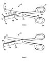
Figure 1 is a perspective view of one embodiment of a pair of surgical scissors; -
Figure 2 is a perspective view of a second embodiment of a pair of surgical scissors; -
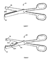
Figure 3 is a perspective view of a third embodiment of a pair of surgical scissors; -
Figure 4 is a perspective view of a fourth embodiment of a pair of surgical scissors; -
Figure 5 is a perspective view of a fifth embodiment of a pair of surgical scissors; -
Figure 6 is a perspective view of a sixth embodiment of a pair of surgical scissors; -
Figure 7 is a perspective view of a seventh embodiment of a pair of surgical scissors; -
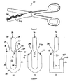
Figures 8(a) to 8(c) are cross-sections of any of the embodiments ofFigures 1 to 7 ; and -
Figures 9(a) to 9(c) are cross-sections of any of the embodiments ofFigures 1 to 7 . -
Figure 10 is a perspective view of a variant of any of the embodiments ofFigures 1 to 7 ; -
Figure 11 is a perspective view of a further variant of any of the embodiments ofFigures 1 to 7 ; -
Figure 12 is a perspective view of an eighth embodiment of a pair of surgical scissors; -
Figure 13 is a perspective view of an eighth embodiment of a pair of surgical scissors; -
Figure 14 is a perspective view of an eighth embodiment of a pair of surgical scissors; -
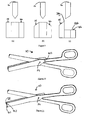
Figure 15 is a perspective view of a ninth embodiment of a pair of surgical scissors according to the invention; and -
Figure 16 is a perspective view of a tenth embodiment of a pair of surgical scissors according to the invention. - Referring firstly to
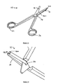
Figure 1 , which is not of the present invention, there is shown a pair ofsurgical scissors 10 having first and secondelongate scissor members scissor member distal blade portion proximal handle portion scissor members blade portion handle portion blade portion cutting edge face outer face distal tip finger opening handle portion - Unconventionally, a restraining
member 46 is associated with thesecond blade portion 18 and may be integral with, or distinct from but attached to, thesecond blade portion 18. An integral restrainingmember 46 is shown inFigure 1 . The restrainingmember 46 is of substantially the same shape as thesecond blade portion 18 and has aninner face 48, anouter face 50 and a flattop edge 52 orthogonal to the inner andouter faces - The inner and
outer faces member 46 lie parallel to the contactingface 32 andouter face 36 of thesecond blade portion 18, with theinner face 48 of the restrainingmember 46 opposed to and spaced from the contactingface 32 of thesecond blade portion 18. The integral restrainingmember 46 andsecond blade portion 18 ofFigure 1 are defined by a U-shaped cross-section (as shown inFigure 8(a) ) wherein thesecond blade portion 18 is one arm of the U and the restrainingmember 46 is the other arm of the U, both arms being joined by acommon base 54. - The contacting
face 32 of thesecond blade portion 18 and theinner face 48 of the restrainingmember 46 define a channel orslot 56 for receiving the cutting edge portion of thefirst blade portion 16 during cutting. When thescissors 10 are closed, a substantial part of thefirst blade portion 16 including itscutting edge 26 lies in the channel orslot 56, sandwiched between thesecond blade portion 18 and the restrainingmember 46. Theouter face 34 of thefirst blade portion 16 and theinner face 48 of the restrainingmember 46 may be spaced from one another to define a small clearance, or they may abut one another in a sliding fit. The restrainingmember 46 may deflect resiliently to facilitate sliding movement of thefirst blade portion 16 if needs be. This will be necessary if the channel orslot 56 is narrower than the thickness of thefirst blade portion 16 to be received in it. - In conventional manner, the cutting action involves squeezing together the
handle portions distal tips blade portions cutting edges second blade portions cutting edges pivot 24 and moves distally along the cutting edges 26, 28 as thedistal tips blade portions - The restraining
member 46 restrains lateral splaying movement of thefirst blade portion 16 away from thesecond blade portion 18. Such lateral movement would be transverse to the length of theblade portions pivotable connection 24. As thedistal tips second blade portions first blade portion 16 is received into the slot orchannel 56 defined by the contactingface 32 of thesecond blade portion 18 and theinner face 48 of the restrainingmember 46. Thefirst blade portion 16 is thereby prevented from splaying away from thesecond blade portion 18 by virtue of contact with the restrainingmember 46. - If there is a clearance between the
first blade portion 16 and the restrainingmember 46, lateral movement of thefirst blade portion 16 is resisted as soon as thefirst blade portion 16 takes up this clearance and itsouter face 34 comes into contact with theinner face 48 of the restrainingmember 46. If there is no clearance, that is if theouter face 34 of thefirst blade portion 16 is in sliding contact with theinner face 48 of the restrainingmember 18 lateral movement of thefirst blade portion 16 is resisted from the outset. In either case, the point or area of contact between thefirst blade portion 16 and the restrainingmember 46 moves along in register with the point of intersection of the opposingcutting edges first blade portion 16 is resisted opposite the point at which the deflecting force is exerted. Advantageously, this enables cutting of tough or slippery items which might otherwise cause the blades to splay away from each other. - The
top edge 52 of the restrainingmember 46 may provide athird cutting edge 58 which is optionally parallel to thecutting edge 28 of thesecond blade portion 18 as shown. Thisthird cutting edge 58 may be co-operable with asecondary cutting edge 60 on thefirst blade portion 16, or may be co-operable with thesame cutting edge 26 on thefirst blade portion 16 that co-operates with thecutting edge 28 of thesecond blade portion 18. The second and third cutting edges 60, 58 inFigure 1 , also shown inFigure 8(a) , are flat and co-planar, lying in a plane orthogonal to the plane in which thefirst blade portion 16 moves about the pivotable connection between thescissor members - The embodiments of
Figures 2 to 7 , which are not of the present invention, differ fromFigure 1 in that the cutting edges of the first and second blade portions and the top edge of the restraining member have been adapted to improve the grip on tissue by the scissors before and during cutting. - In the embodiment of
Figure 2 , thecutting edge 28a of thesecond blade portion 18 and the top edge 52a of the restrainingmember 46 are serrated. The embodiment ofFigure 3 differs from that ofFigure 2 only in that thecutting edge 26b of thefirst blade portion 16 is also serrated. - In the embodiment of
Figure 4 , thecutting edges 26c, 28c of the first andsecond blade portions member 46 are concave-curved. Although not shown, it is feasible that only one cutting edge might be curved in this manner: the other cutting edge(s) may be straight or otherwise shaped. Alternatively, the edges opposite the cutting edges of thedistal blade portions proximal handle portions - In the embodiment of
Figure 5 , thecutting edge 26d of thefirst blade portion 16 has a series of concave curvatures, or peaks and troughs, defining a wavy scalloped line. Conversely in the embodiment ofFigure 6 , only thecutting edge 28e of thesecond blade portion 18 and the top edge 52e of the restrainingmember 46 have a series of concave curvatures. However, it will be apparent that all of the cutting edges could have similar formations. -
Figure 7 shows a further embodiment which differs from that ofFigure 6 in that the concave curvatures of thetop edge 52f of the restrainingmember 46 and the cutting edge 28f of thesecond blade portion 18 are serrated. Alternatively, just one of the scallopededges 28f, 52f may be serrated. Although not shown, it will be apparent that the curved edges of the embodiments shown inFigures 4 and5 may also be serrated. Further alternative embodiments are possible where the scissors comprise at least one flat serrated edge in combination with the serrated and/or non-serrated curved edges described above. Serrated edges are advantageous in that they have an improved grip on the tissues and require sharpening less often than edges without serrations. -
Figures 8(b) and 8(c) andFigures 9(a) to 9(c) , which are not of the present invention, show cross-sectional views of different variants of the scissors of all preceding embodiments.Figures 8(b) and 8(c) differ fromFigures 1 to 7 and8(a) in that the cutting edge 28g of thesecond blade portion 18 is chamfered instead of flat. InFigure 8(b) , the top edge 52g of the restrainingmember 46 is also chamfered. InFigure 8(c) only the cutting edge 28g of thesecond blade portion 18 is chamfered whilst thetop face 52h of the restrainingmember 46 is flat and orthogonal to its the inner andouter faces member 46 is shorter than thesecond blade portion 18, their difference in height being equal to the width of the gap between them i.e. the distance between the opposed contactingface 32 of thesecond blade portion 18 and theinner face 48 of the restrainingmember 46. The shortened restrainingmember 46 allows easier access to thechannel 56 between the restrainingmember 46 and thesecond blade portion 18, which is advantageous for cleaning and sterilising purposes. It will be appreciated that the ratio of the height difference between the restrainingmember 46 and thesecond blade portion 18 to the width of the gap between them may be more or less than 1:1 i.e. the restraining member may be shorter or longer than the width of the gap between the restraining member and the second blade portion. - The variants in
Figures 9(a) to 9(c), 10 and 11 differ from all of the preceding embodiments in that thesecond blade portion 18 and the restrainingmember 46 are not a U shape in cross-section. Otherwise, they correspond toFigures 8(a) to 8(c) respectively: for exampleFigure 9(c) shows a chamfered cutting edge 28g of thesecond blade portion 18 and a flattop edge 52h of the restrainingmember 46 orthogonal to its the inner andouter faces member 46 and thesecond blade portion 18 being equal to the width of the gap between them. Whilst they may still be integral, thesecond blade portion 18 and the restrainingmember 46 do not have a common base extending along their length but instead may be joined at their ends. Alternatively, thesecond blade portion 18 and the restrainingmember 46 may have a common base extending part of the way along their length or along parts of their length. Put another way, thesecond blade portion 18 and the restrainingmember 46 may be bridged at some points along their length by a common base which may be integral with either, or both, thesecond blade portion 18 and the restrainingmember 46, or distinct but attached to thesecond blade portion 18 and the restrainingmember 46. Although not shown, the length of the restraining member may be shorter than the length of the second blade portion. This is particularly beneficial in sharp pointed scissors where a shorter length restraining member prevents the twisting or the crossing-over of the sharp pointed distal tips of the first and second blade portions. -
Figure 10 , which is not of the present invention, shows thesecond blade portion 18 joined to the restrainingmember 46 by a rivet, screw, stud or pin 100 at their proximal ends, and located close to thepivot axis 24 between theblade portion handle portion Figure 11 differs from that shown inFigure 10 in that thesecond blade portion 18 and the restrainingmember 46 are joined by a rivet, screw, stud or pin 102 at theirdistal tips second blade portion 18 and the restrainingmember 46 can be joined by a rivet at both their distal and their proximal tips. - The variants of
Figures 8(b) and (c) , 9,10 and 11 can be applied to all the preceding embodiments, for example the embodiment ofFigure 2 with the cross-sectional appearance ofFigure 9(a) . - A benefit of the variants in
Figures 9(a) to 9(c) and the variants described in the preceding paragraph is that there is less scope for dirt or other detritus to get stuck in the channel or slot between the second blade portion and the restraining member. The fully or partially open bottom allows theslot 56 to be flushed out more readily upon being cleaned or sterilised. The movement of the first blade portion into the slot also lends a self cleaning action in use. - A further alternative embodiment, which is not of the present invention, is shown in
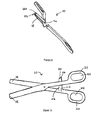
Figures 12 to 14 , which differs from the previous embodiments in that it has a restrainingmember 46a which is substantially the same length as thesecond blade portion 18, extending along the length of thesecond blade portion 18, but is cylindrical in shape, having a substantially circular transverse cross-section. The restrainingmember 46a is a piece of wire or rod and has a free or unattached distal end ortip 104. The other end of the restrainingmember 46a forms the fulcrum at the pivot axis between theblade portions handle portions member 46a extends through a hole in thefirst blade portion 16 and is fixed to thesecond blade portion 18. Advantageously, the rounded profile of the restrainingmember 46a is easy to clean using normal cleaning and sterilising techniques. Although not shown, the restrainingmember 46a may be attached to or integral with thesecond blade portion 18 at both ends of the restraining member which would reduce splaying of thefirst blade portion 16. -
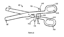
Figures 15 and16 show an embodiment of the scissors of the present invention which differs from the preceding embodiments in that instead of having a restraining member associated with thesecond blade portion 18, at least one of the proximal handle portions of thescissors 10 comprise at least one protuberance or projection in the shape of a wedge extending in a direction transverse to the length of the handle portion, towards the other proximal handle portion. Thewedge projection 110 has athick end 112, athin end 114, and at least oneinclined face 116 which is in sliding contact with the other blade member. Thewedge projection 110 is substantially triangular in cross-section. -
Figure 15 shows a pair ofscissors 10 comprising such awedge projection 110 extending from thefirst handle portion 20 towards thesecond handle portion 22. Thewedge projection 110 is located approximately midway along the length of thefirst handle portion 20. Thethick end 112 of thewedge projection 110 may be integral with, or be distinct from but attached to, thefirst handle portion 20, in a fixed position with respect to thefirst handle portion 20. Thewedge projection 110 may also be arranged so that it is moveable along thefirst handle portion 20. Optionally, thescissors 10 having themoveable wedge projection 110 may comprise a fixing mechanism to allow the moveable wedge projection to be fixed or secured in position along thefirst handle portion 20. - In use, as the
handle portions inclined face 116 of thewedge projection 110 and the opposing face (not shown) of thesecond handle portion 22 slide relative to each other. The area of contact between them on theinclined face 116 of thewedge projection 110 moves from itsthin end 114 towards itsthick end 112, resulting in the first andsecond handle portions blade portions blade portions blade portions blade portions wedge projection 110 and the angle of itsinclined face 116 is such that thewedge projection 110 does not impart any lateral force between thehandle portions - The
wedge face 116 is continuous such that the wedging force increases, or at least does not decrease, during and throughout the cutting stroke for effective cutting. This is distinguished from known ratchet mechanisms on handle portions which can be said to comprise a series of wedges with discontinuous wedge faces which do not provide a continuous wedging force during a cutting stroke. -
Figure 16 differs from the embodiment shown inFigure 15 in that thesecond handle portion 22 also comprises awedge projection 110 extending towards thefirst handle portion 20. Thissecond wedge projection 110 is similar to that ofFigure 15 both in appearance and functionality. Theinclined face 116 of thesecond wedge projection 110 is in sliding contact with the opposing face of thefirst handle portion 20. Although not shown, thehandle portions wedge projections 110 may be fixed or moveable with respect to thehandle portions - The advantage of having one or more
moveable wedge projections 110 is that the wedging effect, and hence the force that splays thehandle portions blade portions - The scissors described herein may be embodied in other specific forms without departing from the essential attributes. For example, the outer faces of the second blade portion and the restraining member do not have to be parallel. It is also possible for the first blade member to have an associated restraining member, defining a channel or slot that receives and minimises deflection of the second blade member. However, it will be apparent that the restraining member may also have the effect of stiffening the blade member with which it is associated. The restraining member need not be of substantially the same shape or length as the second blade portion. Although the scissors of the present invention have been described as surgical scissors, they may also be equally suitable for non-surgical and non-medical applications such as cutting textiles and other materials.
Claims (6)
- Scissors (10) having first and second pivotably connected elongate blade members, each blade member having a handle portion (20, 22) and a blade portion (16, 18), wherein at least one of the handle portions (20) comprises a wedge means (110) co-operable with the other handle portion (22) during a cutting stroke to urge the handle portions (20, 22) apart laterally while biasing the blade portions (16, 18) laterally together to oppose relative lateral movement of the blade portions (16, 18) away from each other during the cutting stroke, characterised in that the wedge means (110) has a thick end (112) and a thin end (114), and an area of contact between the wedge means (110) and the other handle portion (22) moves from the thin end (114) towards the thick end (112) during the cutting stroke to provide a continuous wedging force throughout the cutting stroke.
- The scissors (10) of Claim 1, wherein the wedge means (110) has an inclined face (116) which is in sliding contact with the other handle portion (22) during the cutting stroke.
- The scissors (10) of Claim 1 or Claim 2, wherein the wedge means (110) protrude from one handle portion (20) towards the other handle portion (22).
- The scissors (10) of any preceding Claim, wherein the wedge means (110) is located approximately midway along the length of the handle portion (20).
- The scissors (10) of any preceding Claim, further comprising a second wedge means (110) associated with one of the handle portions (20, 22).
- The scissors (10) of Claim 5, wherein the second wedge means (110) is associated with the other handle portion (22).
Applications Claiming Priority (2)
| Application Number | Priority Date | Filing Date | Title |
|---|---|---|---|
| GB0503210A GB2423269A (en) | 2005-02-16 | 2005-02-16 | Scissors with laterally restrained blades |
| PCT/GB2006/000544 WO2006087554A1 (en) | 2005-02-16 | 2006-02-16 | Improvements in or relating to scissors |
Publications (2)
| Publication Number | Publication Date |
|---|---|
| EP1851013A1 EP1851013A1 (en) | 2007-11-07 |
| EP1851013B1 true EP1851013B1 (en) | 2012-01-11 |
Family
ID=34385583
Family Applications (1)
| Application Number | Title | Priority Date | Filing Date |
|---|---|---|---|
| EP06709781A Not-in-force EP1851013B1 (en) | 2005-02-16 | 2006-02-16 | Improvements in or relating to scissors |
Country Status (6)
| Country | Link |
|---|---|
| US (1) | US20080004650A1 (en) |
| EP (1) | EP1851013B1 (en) |
| JP (1) | JP2008529700A (en) |
| AT (1) | ATE540784T1 (en) |
| GB (1) | GB2423269A (en) |
| WO (1) | WO2006087554A1 (en) |
Cited By (1)
| Publication number | Priority date | Publication date | Assignee | Title |
|---|---|---|---|---|
| RU198842U1 (en) * | 2020-04-16 | 2020-07-30 | Александр Григорьевич Сонис | DEVICE FOR PARTIAL RESECTION OF THE NAIL PLATE |
Families Citing this family (97)
| Publication number | Priority date | Publication date | Assignee | Title |
|---|---|---|---|---|
| US20080045990A1 (en) * | 2006-08-15 | 2008-02-21 | Susan Lynn Valerio | Combination medical bandage scissors |
| US20080200911A1 (en) * | 2007-02-15 | 2008-08-21 | Long Gary L | Electrical ablation apparatus, system, and method |
| US20080200934A1 (en) * | 2007-02-15 | 2008-08-21 | Fox William D | Surgical devices and methods using magnetic force to form an anastomosis |
| US20080200933A1 (en) * | 2007-02-15 | 2008-08-21 | Bakos Gregory J | Surgical devices and methods for forming an anastomosis between organs by gaining access thereto through a natural orifice in the body |
| US20080200755A1 (en) * | 2007-02-15 | 2008-08-21 | Bakos Gregory J | Method and device for retrieving suture tags |
| US7655004B2 (en) * | 2007-02-15 | 2010-02-02 | Ethicon Endo-Surgery, Inc. | Electroporation ablation apparatus, system, and method |
| US20080200762A1 (en) * | 2007-02-16 | 2008-08-21 | Stokes Michael J | Flexible endoscope shapelock |
| US7815662B2 (en) * | 2007-03-08 | 2010-10-19 | Ethicon Endo-Surgery, Inc. | Surgical suture anchors and deployment device |
| US8075572B2 (en) * | 2007-04-26 | 2011-12-13 | Ethicon Endo-Surgery, Inc. | Surgical suturing apparatus |
| US8100922B2 (en) * | 2007-04-27 | 2012-01-24 | Ethicon Endo-Surgery, Inc. | Curved needle suturing tool |
| US20090054728A1 (en) * | 2007-08-21 | 2009-02-26 | Trusty Robert M | Manipulatable guide system and methods for natural orifice translumenal endoscopic surgery |
| US8579897B2 (en) | 2007-11-21 | 2013-11-12 | Ethicon Endo-Surgery, Inc. | Bipolar forceps |
| US8262655B2 (en) * | 2007-11-21 | 2012-09-11 | Ethicon Endo-Surgery, Inc. | Bipolar forceps |
| US8568410B2 (en) * | 2007-08-31 | 2013-10-29 | Ethicon Endo-Surgery, Inc. | Electrical ablation surgical instruments |
| US20090062788A1 (en) * | 2007-08-31 | 2009-03-05 | Long Gary L | Electrical ablation surgical instruments |
| US20090062795A1 (en) * | 2007-08-31 | 2009-03-05 | Ethicon Endo-Surgery, Inc. | Electrical ablation surgical instruments |
| US8480657B2 (en) | 2007-10-31 | 2013-07-09 | Ethicon Endo-Surgery, Inc. | Detachable distal overtube section and methods for forming a sealable opening in the wall of an organ |
| US20090112059A1 (en) | 2007-10-31 | 2009-04-30 | Nobis Rudolph H | Apparatus and methods for closing a gastrotomy |
| US20090131751A1 (en) * | 2007-11-20 | 2009-05-21 | Spivey James T | Anal surgical instrument guides |
| US20090182332A1 (en) * | 2008-01-15 | 2009-07-16 | Ethicon Endo-Surgery, Inc. | In-line electrosurgical forceps |
| US8262680B2 (en) | 2008-03-10 | 2012-09-11 | Ethicon Endo-Surgery, Inc. | Anastomotic device |
| US20090281559A1 (en) * | 2008-05-06 | 2009-11-12 | Ethicon Endo-Surgery, Inc. | Anastomosis patch |
| US8771260B2 (en) | 2008-05-30 | 2014-07-08 | Ethicon Endo-Surgery, Inc. | Actuating and articulating surgical device |
| US8114072B2 (en) | 2008-05-30 | 2012-02-14 | Ethicon Endo-Surgery, Inc. | Electrical ablation device |
| US8652150B2 (en) * | 2008-05-30 | 2014-02-18 | Ethicon Endo-Surgery, Inc. | Multifunction surgical device |
| US8070759B2 (en) | 2008-05-30 | 2011-12-06 | Ethicon Endo-Surgery, Inc. | Surgical fastening device |
| US8679003B2 (en) * | 2008-05-30 | 2014-03-25 | Ethicon Endo-Surgery, Inc. | Surgical device and endoscope including same |
| US8317806B2 (en) * | 2008-05-30 | 2012-11-27 | Ethicon Endo-Surgery, Inc. | Endoscopic suturing tension controlling and indication devices |
| US8906035B2 (en) * | 2008-06-04 | 2014-12-09 | Ethicon Endo-Surgery, Inc. | Endoscopic drop off bag |
| US8403926B2 (en) | 2008-06-05 | 2013-03-26 | Ethicon Endo-Surgery, Inc. | Manually articulating devices |
| US8361112B2 (en) | 2008-06-27 | 2013-01-29 | Ethicon Endo-Surgery, Inc. | Surgical suture arrangement |
| US20100010303A1 (en) * | 2008-07-09 | 2010-01-14 | Ethicon Endo-Surgery, Inc. | Inflatable access device |
| US20100010294A1 (en) * | 2008-07-10 | 2010-01-14 | Ethicon Endo-Surgery, Inc. | Temporarily positionable medical devices |
| US8262563B2 (en) * | 2008-07-14 | 2012-09-11 | Ethicon Endo-Surgery, Inc. | Endoscopic translumenal articulatable steerable overtube |
| US8888792B2 (en) | 2008-07-14 | 2014-11-18 | Ethicon Endo-Surgery, Inc. | Tissue apposition clip application devices and methods |
| US8211125B2 (en) | 2008-08-15 | 2012-07-03 | Ethicon Endo-Surgery, Inc. | Sterile appliance delivery device for endoscopic procedures |
| US8529563B2 (en) | 2008-08-25 | 2013-09-10 | Ethicon Endo-Surgery, Inc. | Electrical ablation devices |
| US20100048990A1 (en) * | 2008-08-25 | 2010-02-25 | Ethicon Endo-Surgery, Inc. | Endoscopic needle for natural orifice translumenal endoscopic surgery |
| US8241204B2 (en) * | 2008-08-29 | 2012-08-14 | Ethicon Endo-Surgery, Inc. | Articulating end cap |
| US8480689B2 (en) | 2008-09-02 | 2013-07-09 | Ethicon Endo-Surgery, Inc. | Suturing device |
| US8409200B2 (en) * | 2008-09-03 | 2013-04-02 | Ethicon Endo-Surgery, Inc. | Surgical grasping device |
| US8114119B2 (en) * | 2008-09-09 | 2012-02-14 | Ethicon Endo-Surgery, Inc. | Surgical grasping device |
| US20100076451A1 (en) * | 2008-09-19 | 2010-03-25 | Ethicon Endo-Surgery, Inc. | Rigidizable surgical instrument |
| US8337394B2 (en) * | 2008-10-01 | 2012-12-25 | Ethicon Endo-Surgery, Inc. | Overtube with expandable tip |
| DE102008057624B4 (en) * | 2008-11-10 | 2013-11-14 | Simon Siewert | pinking shears |
| US8157834B2 (en) * | 2008-11-25 | 2012-04-17 | Ethicon Endo-Surgery, Inc. | Rotational coupling device for surgical instrument with flexible actuators |
| US8172772B2 (en) | 2008-12-11 | 2012-05-08 | Ethicon Endo-Surgery, Inc. | Specimen retrieval device |
| US20100152539A1 (en) * | 2008-12-17 | 2010-06-17 | Ethicon Endo-Surgery, Inc. | Positionable imaging medical devices |
| US8828031B2 (en) * | 2009-01-12 | 2014-09-09 | Ethicon Endo-Surgery, Inc. | Apparatus for forming an anastomosis |
| US8361066B2 (en) | 2009-01-12 | 2013-01-29 | Ethicon Endo-Surgery, Inc. | Electrical ablation devices |
| US20100191050A1 (en) * | 2009-01-23 | 2010-07-29 | Ethicon Endo-Surgery, Inc. | Variable length accessory for guiding a flexible endoscopic tool |
| US20100191267A1 (en) * | 2009-01-26 | 2010-07-29 | Ethicon Endo-Surgery, Inc. | Rotary needle for natural orifice translumenal endoscopic surgery |
| US9226772B2 (en) | 2009-01-30 | 2016-01-05 | Ethicon Endo-Surgery, Inc. | Surgical device |
| US8252057B2 (en) | 2009-01-30 | 2012-08-28 | Ethicon Endo-Surgery, Inc. | Surgical access device |
| US8037591B2 (en) | 2009-02-02 | 2011-10-18 | Ethicon Endo-Surgery, Inc. | Surgical scissors |
| US20100298642A1 (en) * | 2009-05-19 | 2010-11-25 | Ethicon Endo-Surgery, Inc. | Manipulatable guide system and methods for natural orifice translumenal endoscopic surgery |
| US20110098694A1 (en) * | 2009-10-28 | 2011-04-28 | Ethicon Endo-Surgery, Inc. | Methods and instruments for treating cardiac tissue through a natural orifice |
| US20110098704A1 (en) | 2009-10-28 | 2011-04-28 | Ethicon Endo-Surgery, Inc. | Electrical ablation devices |
| US8608652B2 (en) | 2009-11-05 | 2013-12-17 | Ethicon Endo-Surgery, Inc. | Vaginal entry surgical devices, kit, system, and method |
| US20110115891A1 (en) * | 2009-11-13 | 2011-05-19 | Ethicon Endo-Surgery, Inc. | Energy delivery apparatus, system, and method for deployable medical electronic devices |
| US20110152610A1 (en) * | 2009-12-17 | 2011-06-23 | Ethicon Endo-Surgery, Inc. | Intralumenal accessory tip for endoscopic sheath arrangements |
| US8353487B2 (en) | 2009-12-17 | 2013-01-15 | Ethicon Endo-Surgery, Inc. | User interface support devices for endoscopic surgical instruments |
| US8496574B2 (en) | 2009-12-17 | 2013-07-30 | Ethicon Endo-Surgery, Inc. | Selectively positionable camera for surgical guide tube assembly |
| US20110152878A1 (en) * | 2009-12-17 | 2011-06-23 | Ethicon Endo-Surgery, Inc. | Interface systems for aiding clinicians in controlling and manipulating at least one endoscopic surgical instrument and a cable controlled guide tube system |
| US8506564B2 (en) | 2009-12-18 | 2013-08-13 | Ethicon Endo-Surgery, Inc. | Surgical instrument comprising an electrode |
| US9028483B2 (en) * | 2009-12-18 | 2015-05-12 | Ethicon Endo-Surgery, Inc. | Surgical instrument comprising an electrode |
| US20110160514A1 (en) * | 2009-12-31 | 2011-06-30 | Ethicon Endo-Surgery, Inc. | Electrical ablation devices |
| US9005198B2 (en) | 2010-01-29 | 2015-04-14 | Ethicon Endo-Surgery, Inc. | Surgical instrument comprising an electrode |
| US20110190764A1 (en) * | 2010-01-29 | 2011-08-04 | Ethicon Endo-Surgery, Inc. | Surgical instrument comprising an electrode |
| US20120115104A1 (en) * | 2010-08-17 | 2012-05-10 | Empire Technology Development Llc | Multi-rooted tooth extraction device |
| JP4693194B1 (en) * | 2010-10-29 | 2011-06-01 | 正一 中村 | Surgical instruments |
| US10092291B2 (en) | 2011-01-25 | 2018-10-09 | Ethicon Endo-Surgery, Inc. | Surgical instrument with selectively rigidizable features |
| JP5707575B2 (en) * | 2011-02-10 | 2015-04-30 | 学校法人金沢工業大学 | Flexible endoscopic instrument and acupuncture forceps |
| US9597810B2 (en) | 2011-02-10 | 2017-03-21 | Samuel George | Scissors |
| US9254169B2 (en) | 2011-02-28 | 2016-02-09 | Ethicon Endo-Surgery, Inc. | Electrical ablation devices and methods |
| US9233241B2 (en) | 2011-02-28 | 2016-01-12 | Ethicon Endo-Surgery, Inc. | Electrical ablation devices and methods |
| US9314620B2 (en) | 2011-02-28 | 2016-04-19 | Ethicon Endo-Surgery, Inc. | Electrical ablation devices and methods |
| WO2012125785A1 (en) | 2011-03-17 | 2012-09-20 | Ethicon Endo-Surgery, Inc. | Hand held surgical device for manipulating an internal magnet assembly within a patient |
| US8986199B2 (en) | 2012-02-17 | 2015-03-24 | Ethicon Endo-Surgery, Inc. | Apparatus and methods for cleaning the lens of an endoscope |
| US9427255B2 (en) | 2012-05-14 | 2016-08-30 | Ethicon Endo-Surgery, Inc. | Apparatus for introducing a steerable camera assembly into a patient |
| US9078662B2 (en) | 2012-07-03 | 2015-07-14 | Ethicon Endo-Surgery, Inc. | Endoscopic cap electrode and method for using the same |
| JP6028429B2 (en) * | 2012-07-10 | 2016-11-16 | 富士ゼロックス株式会社 | Display control apparatus, service providing apparatus, and program |
| US9545290B2 (en) | 2012-07-30 | 2017-01-17 | Ethicon Endo-Surgery, Inc. | Needle probe guide |
| US9572623B2 (en) | 2012-08-02 | 2017-02-21 | Ethicon Endo-Surgery, Inc. | Reusable electrode and disposable sheath |
| US10314649B2 (en) | 2012-08-02 | 2019-06-11 | Ethicon Endo-Surgery, Inc. | Flexible expandable electrode and method of intraluminal delivery of pulsed power |
| US9277957B2 (en) | 2012-08-15 | 2016-03-08 | Ethicon Endo-Surgery, Inc. | Electrosurgical devices and methods |
| US10098527B2 (en) | 2013-02-27 | 2018-10-16 | Ethidcon Endo-Surgery, Inc. | System for performing a minimally invasive surgical procedure |
| USD753973S1 (en) * | 2015-01-07 | 2016-04-19 | Peacekorea Co., Ltd. | Scissors |
| KR101677261B1 (en) * | 2015-08-24 | 2016-11-17 | 신우성 | Cutter of the femoral head of pet |
| CN105708525B (en) * | 2016-03-29 | 2018-03-23 | 中国人民解放军第二军医大学 | A kind of quick skin apparatus processed of novel partculate skin |
| USD823538S1 (en) * | 2016-05-12 | 2018-07-17 | Maria Ruggaber | Eyelash applicator |
| DE102016116624A1 (en) * | 2016-09-06 | 2018-03-22 | Karl Leibinger Medizintechnik Gmbh & Co. Kg | Medical instrument with cleaning gap in the closure area |
| EP3518785B1 (en) * | 2016-11-23 | 2021-05-19 | Boston Scientific Scimed, Inc. | Biopsy devices |
| USD833689S1 (en) * | 2017-01-25 | 2018-11-13 | Angel Namoi Carrigan | Animal grooming safety scissors |
| US11617429B2 (en) * | 2017-03-10 | 2023-04-04 | John Lazar | Medical scraping tool for human nails or skin |
| DE102019134018B4 (en) | 2019-12-11 | 2022-04-14 | Karl Storz Se & Co. Kg | Micro-invasive medical scissors |
| USD1002311S1 (en) * | 2021-06-16 | 2023-10-24 | Mylenya Crawford | Shear razor device |
Family Cites Families (36)
| Publication number | Priority date | Publication date | Assignee | Title |
|---|---|---|---|---|
| US69960A (en) * | 1867-10-22 | Improvement in soissoes and shears | ||
| US183404A (en) * | 1876-10-17 | Improvement in band-cutting shears | ||
| US2315326A (en) * | 1943-03-30 | Surgical instrument | ||
| US865918A (en) * | 1907-01-28 | 1907-09-10 | Hunter Arnold | Cutting-tool. |
| US1101181A (en) * | 1913-09-04 | 1914-06-23 | Louis M Schmidt | Pliers and similar tool. |
| US1956588A (en) * | 1932-03-04 | 1934-05-01 | Bard Parker Company Inc | Scissors |
| US2025345A (en) * | 1934-01-30 | 1935-12-24 | Hyman H Harris | Surgical instrument |
| US2027190A (en) * | 1935-03-21 | 1936-01-07 | Trane Co | Valve |
| US2195353A (en) * | 1937-09-16 | 1940-03-26 | Byron L Atchison | Scissors |
| US2127190A (en) * | 1938-02-02 | 1938-08-16 | David I Solomon | Combined surgical instrument |
| US2627656A (en) * | 1947-02-06 | 1953-02-10 | Richartz Paul | Scissors with twist in each blade |
| US2965967A (en) * | 1958-10-24 | 1960-12-27 | Wahl Clipper Corp | Scissors |
| US3548496A (en) * | 1968-07-15 | 1970-12-22 | Alco Standard Corp | Filament clip scissors |
| US3750282A (en) * | 1972-10-04 | 1973-08-07 | Web Prod Inc | Scissors |
| US3972333A (en) * | 1973-03-02 | 1976-08-03 | Leveen Harry H | Disposable surgical tool |
| US3846910A (en) * | 1973-09-24 | 1974-11-12 | True Temper Corp | Shear bumper |
| US3921640A (en) * | 1974-03-22 | 1975-11-25 | Int Paper Co | Disposable surgical instruments |
| US4049002A (en) * | 1975-07-18 | 1977-09-20 | Bio-Medicus, Inc. | Fluid conveying surgical instrument |
| US4009899A (en) * | 1975-10-16 | 1977-03-01 | Fluoroware, Inc. | Wafer tongs |
| USD250629S (en) * | 1977-01-31 | 1978-12-26 | Oy Fiskars Ab | Thread nipper |
| US4212305A (en) * | 1978-03-02 | 1980-07-15 | Dart Industries Inc. | Disposable forceps |
| DE3325602C2 (en) * | 1983-07-15 | 1985-09-26 | Karl-Heinz 8631 Ahorn Kantwerk | Combination tool |
| US4611592A (en) * | 1983-08-05 | 1986-09-16 | Talboy Glenn E | Clamp for holding surgical lines |
| US5065516A (en) * | 1987-05-11 | 1991-11-19 | Andrew Tool Company | Disassemblable scissors means |
| US5007170A (en) * | 1989-03-14 | 1991-04-16 | Nt Incorporated | Scissors for both right and left hand use |
| US5320636A (en) * | 1991-04-04 | 1994-06-14 | Symbiosis Corporation | Endoscopic scissors instrument with cammed surface end effectors |
| CA2113967A1 (en) * | 1993-03-30 | 1994-10-01 | Erkki Olavi Linden | Tool having integral hinge member |
| US5469626A (en) * | 1993-04-23 | 1995-11-28 | Vogel Brothers Corporation | Scissors |
| US5560107A (en) * | 1995-08-14 | 1996-10-01 | Herbert; Paul W. | Cutting tool |
| US5711075A (en) * | 1996-04-25 | 1998-01-27 | Wolf; Jeffrey A. | Unitarily formed plastic soft tissue nipper |
| US5964033A (en) * | 1996-04-25 | 1999-10-12 | Wolf; Jeffrey A. | Soft tissue nipper with unitarily formed plastic support for nipper blades |
| US5925052A (en) * | 1996-06-26 | 1999-07-20 | Simmons; Paul L. | Umbilical surgical scissors |
| GB2345857B (en) * | 1999-01-23 | 2000-12-06 | Ahmad Fahmi Juanroyee | Scissors-clip diathermy (SCD) |
| US6702820B2 (en) * | 2000-10-24 | 2004-03-09 | John B. Mazur | Surgical cutting instrument having concative jaw tips |
| US6976992B2 (en) * | 2002-07-16 | 2005-12-20 | Suturecut, Llc | Dual-function medical instrument |
| TW201144005A (en) * | 2010-06-04 | 2011-12-16 | Allprofessional Meg Co Ltd | Clipper |
-
2005
- 2005-02-16 GB GB0503210A patent/GB2423269A/en not_active Withdrawn
-
2006
- 2006-02-16 WO PCT/GB2006/000544 patent/WO2006087554A1/en active Application Filing
- 2006-02-16 AT AT06709781T patent/ATE540784T1/en active
- 2006-02-16 JP JP2007555698A patent/JP2008529700A/en active Pending
- 2006-02-16 EP EP06709781A patent/EP1851013B1/en not_active Not-in-force
-
2007
- 2007-08-13 US US11/891,825 patent/US20080004650A1/en not_active Abandoned
Cited By (1)
| Publication number | Priority date | Publication date | Assignee | Title |
|---|---|---|---|---|
| RU198842U1 (en) * | 2020-04-16 | 2020-07-30 | Александр Григорьевич Сонис | DEVICE FOR PARTIAL RESECTION OF THE NAIL PLATE |
Also Published As
| Publication number | Publication date |
|---|---|
| JP2008529700A (en) | 2008-08-07 |
| ATE540784T1 (en) | 2012-01-15 |
| GB2423269A (en) | 2006-08-23 |
| EP1851013A1 (en) | 2007-11-07 |
| WO2006087554A1 (en) | 2006-08-24 |
| US20080004650A1 (en) | 2008-01-03 |
| GB0503210D0 (en) | 2005-03-23 |
Similar Documents
| Publication | Publication Date | Title |
|---|---|---|
| EP1851013B1 (en) | Improvements in or relating to scissors | |
| US5431674A (en) | Compound motion cutting device | |
| US5569258A (en) | Laminectomy rongeurs | |
| US20060212045A1 (en) | Surgical suture cutter | |
| US6419684B1 (en) | End-cutting shaver blade for axial resection | |
| AU653691B2 (en) | Laparoscopic hook scissors | |
| US5209755A (en) | Dermal exciser | |
| CA2313671C (en) | Curved laparoscopic scissor having two arcs of curvature | |
| CN110547851B (en) | Method and apparatus for threading suture | |
| US5282817A (en) | Actuating handle for multipurpose surgical instrument | |
| US4669470A (en) | Surgical forceps/scissors | |
| US5292330A (en) | Retractable surgical instrument with curved operative element | |
| US4597385A (en) | Biopsy instrument | |
| JP5307142B2 (en) | Surgical cutting instrument | |
| US20060041266A1 (en) | Surgical scalpel | |
| EP2537646A1 (en) | Multipurpose shears | |
| US3915169A (en) | Surgical knife having malleable shank | |
| US20060260135A1 (en) | Gripcut tool | |
| US10220528B2 (en) | Scissors | |
| CN108778200B (en) | Film layering device | |
| US20160302801A1 (en) | Disposable kerrison rongeur | |
| US8114107B2 (en) | Laparoscopic scissor blades | |
| US6176866B1 (en) | Scissors | |
| US20120078282A1 (en) | Scissor system for endoscopic and open surgical procedure | |
| US10925618B2 (en) | Rongeur with a disposable attribute |
Legal Events
| Date | Code | Title | Description |
|---|---|---|---|
| PUAI | Public reference made under article 153(3) epc to a published international application that has entered the european phase |
Free format text: ORIGINAL CODE: 0009012 |
|
| 17P | Request for examination filed |
Effective date: 20070904 |
|
| AK | Designated contracting states |
Kind code of ref document: A1 Designated state(s): AT BE BG CH CY CZ DE DK EE ES FI FR GB GR HU IE IS IT LI LT LU LV MC NL PL PT RO SE SI SK TR |
|
| DAX | Request for extension of the european patent (deleted) | ||
| 17Q | First examination report despatched |
Effective date: 20080730 |
|
| GRAP | Despatch of communication of intention to grant a patent |
Free format text: ORIGINAL CODE: EPIDOSNIGR1 |
|
| GRAS | Grant fee paid |
Free format text: ORIGINAL CODE: EPIDOSNIGR3 |
|
| GRAA | (expected) grant |
Free format text: ORIGINAL CODE: 0009210 |
|
| AK | Designated contracting states |
Kind code of ref document: B1 Designated state(s): AT BE BG CH CY CZ DE DK EE ES FI FR GB GR HU IE IS IT LI LT LU LV MC NL PL PT RO SE SI SK TR |
|
| REG | Reference to a national code |
Ref country code: GB Ref legal event code: FG4D |
|
| REG | Reference to a national code |
Ref country code: CH Ref legal event code: EP |
|
| REG | Reference to a national code |
Ref country code: AT Ref legal event code: REF Ref document number: 540784 Country of ref document: AT Kind code of ref document: T Effective date: 20120115 |
|
| REG | Reference to a national code |
Ref country code: IE Ref legal event code: FG4D |
|
| REG | Reference to a national code |
Ref country code: DE Ref legal event code: R096 Ref document number: 602006026980 Country of ref document: DE Effective date: 20120315 |
|
| REG | Reference to a national code |
Ref country code: NL Ref legal event code: VDEP Effective date: 20120111 |
|
| PG25 | Lapsed in a contracting state [announced via postgrant information from national office to epo] |
Ref country code: SI Free format text: LAPSE BECAUSE OF FAILURE TO SUBMIT A TRANSLATION OF THE DESCRIPTION OR TO PAY THE FEE WITHIN THE PRESCRIBED TIME-LIMIT Effective date: 20120111 |
|
| LTIE | Lt: invalidation of european patent or patent extension |
Effective date: 20120111 |
|
| PG25 | Lapsed in a contracting state [announced via postgrant information from national office to epo] |
Ref country code: BE Free format text: LAPSE BECAUSE OF FAILURE TO SUBMIT A TRANSLATION OF THE DESCRIPTION OR TO PAY THE FEE WITHIN THE PRESCRIBED TIME-LIMIT Effective date: 20120111 Ref country code: BG Free format text: LAPSE BECAUSE OF FAILURE TO SUBMIT A TRANSLATION OF THE DESCRIPTION OR TO PAY THE FEE WITHIN THE PRESCRIBED TIME-LIMIT Effective date: 20120411 Ref country code: NL Free format text: LAPSE BECAUSE OF FAILURE TO SUBMIT A TRANSLATION OF THE DESCRIPTION OR TO PAY THE FEE WITHIN THE PRESCRIBED TIME-LIMIT Effective date: 20120111 Ref country code: IS Free format text: LAPSE BECAUSE OF FAILURE TO SUBMIT A TRANSLATION OF THE DESCRIPTION OR TO PAY THE FEE WITHIN THE PRESCRIBED TIME-LIMIT Effective date: 20120511 Ref country code: LT Free format text: LAPSE BECAUSE OF FAILURE TO SUBMIT A TRANSLATION OF THE DESCRIPTION OR TO PAY THE FEE WITHIN THE PRESCRIBED TIME-LIMIT Effective date: 20120111 |
|
| PG25 | Lapsed in a contracting state [announced via postgrant information from national office to epo] |
Ref country code: GR Free format text: LAPSE BECAUSE OF FAILURE TO SUBMIT A TRANSLATION OF THE DESCRIPTION OR TO PAY THE FEE WITHIN THE PRESCRIBED TIME-LIMIT Effective date: 20120412 Ref country code: PT Free format text: LAPSE BECAUSE OF FAILURE TO SUBMIT A TRANSLATION OF THE DESCRIPTION OR TO PAY THE FEE WITHIN THE PRESCRIBED TIME-LIMIT Effective date: 20120511 Ref country code: LV Free format text: LAPSE BECAUSE OF FAILURE TO SUBMIT A TRANSLATION OF THE DESCRIPTION OR TO PAY THE FEE WITHIN THE PRESCRIBED TIME-LIMIT Effective date: 20120111 Ref country code: FI Free format text: LAPSE BECAUSE OF FAILURE TO SUBMIT A TRANSLATION OF THE DESCRIPTION OR TO PAY THE FEE WITHIN THE PRESCRIBED TIME-LIMIT Effective date: 20120111 Ref country code: PL Free format text: LAPSE BECAUSE OF FAILURE TO SUBMIT A TRANSLATION OF THE DESCRIPTION OR TO PAY THE FEE WITHIN THE PRESCRIBED TIME-LIMIT Effective date: 20120111 |
|
| REG | Reference to a national code |
Ref country code: AT Ref legal event code: MK05 Ref document number: 540784 Country of ref document: AT Kind code of ref document: T Effective date: 20120111 |
|
| PG25 | Lapsed in a contracting state [announced via postgrant information from national office to epo] |
Ref country code: MC Free format text: LAPSE BECAUSE OF NON-PAYMENT OF DUE FEES Effective date: 20120229 Ref country code: CY Free format text: LAPSE BECAUSE OF FAILURE TO SUBMIT A TRANSLATION OF THE DESCRIPTION OR TO PAY THE FEE WITHIN THE PRESCRIBED TIME-LIMIT Effective date: 20120111 |
|
| REG | Reference to a national code |
Ref country code: CH Ref legal event code: PL |
|
| PG25 | Lapsed in a contracting state [announced via postgrant information from national office to epo] |
Ref country code: CZ Free format text: LAPSE BECAUSE OF FAILURE TO SUBMIT A TRANSLATION OF THE DESCRIPTION OR TO PAY THE FEE WITHIN THE PRESCRIBED TIME-LIMIT Effective date: 20120111 Ref country code: EE Free format text: LAPSE BECAUSE OF FAILURE TO SUBMIT A TRANSLATION OF THE DESCRIPTION OR TO PAY THE FEE WITHIN THE PRESCRIBED TIME-LIMIT Effective date: 20120111 Ref country code: RO Free format text: LAPSE BECAUSE OF FAILURE TO SUBMIT A TRANSLATION OF THE DESCRIPTION OR TO PAY THE FEE WITHIN THE PRESCRIBED TIME-LIMIT Effective date: 20120111 Ref country code: SE Free format text: LAPSE BECAUSE OF FAILURE TO SUBMIT A TRANSLATION OF THE DESCRIPTION OR TO PAY THE FEE WITHIN THE PRESCRIBED TIME-LIMIT Effective date: 20120111 Ref country code: CH Free format text: LAPSE BECAUSE OF NON-PAYMENT OF DUE FEES Effective date: 20120229 Ref country code: LI Free format text: LAPSE BECAUSE OF NON-PAYMENT OF DUE FEES Effective date: 20120229 Ref country code: DK Free format text: LAPSE BECAUSE OF FAILURE TO SUBMIT A TRANSLATION OF THE DESCRIPTION OR TO PAY THE FEE WITHIN THE PRESCRIBED TIME-LIMIT Effective date: 20120111 |
|
| PLBE | No opposition filed within time limit |
Free format text: ORIGINAL CODE: 0009261 |
|
| STAA | Information on the status of an ep patent application or granted ep patent |
Free format text: STATUS: NO OPPOSITION FILED WITHIN TIME LIMIT |
|
| REG | Reference to a national code |
Ref country code: IE Ref legal event code: MM4A |
|
| REG | Reference to a national code |
Ref country code: FR Ref legal event code: ST Effective date: 20121031 |
|
| PG25 | Lapsed in a contracting state [announced via postgrant information from national office to epo] |
Ref country code: IT Free format text: LAPSE BECAUSE OF FAILURE TO SUBMIT A TRANSLATION OF THE DESCRIPTION OR TO PAY THE FEE WITHIN THE PRESCRIBED TIME-LIMIT Effective date: 20120111 Ref country code: SK Free format text: LAPSE BECAUSE OF FAILURE TO SUBMIT A TRANSLATION OF THE DESCRIPTION OR TO PAY THE FEE WITHIN THE PRESCRIBED TIME-LIMIT Effective date: 20120111 |
|
| 26N | No opposition filed |
Effective date: 20121012 |
|
| PG25 | Lapsed in a contracting state [announced via postgrant information from national office to epo] |
Ref country code: AT Free format text: LAPSE BECAUSE OF FAILURE TO SUBMIT A TRANSLATION OF THE DESCRIPTION OR TO PAY THE FEE WITHIN THE PRESCRIBED TIME-LIMIT Effective date: 20120111 Ref country code: IE Free format text: LAPSE BECAUSE OF NON-PAYMENT OF DUE FEES Effective date: 20120216 Ref country code: FR Free format text: LAPSE BECAUSE OF NON-PAYMENT OF DUE FEES Effective date: 20120312 |
|
| REG | Reference to a national code |
Ref country code: DE Ref legal event code: R097 Ref document number: 602006026980 Country of ref document: DE Effective date: 20121012 |
|
| PG25 | Lapsed in a contracting state [announced via postgrant information from national office to epo] |
Ref country code: ES Free format text: LAPSE BECAUSE OF FAILURE TO SUBMIT A TRANSLATION OF THE DESCRIPTION OR TO PAY THE FEE WITHIN THE PRESCRIBED TIME-LIMIT Effective date: 20120422 |
|
| PG25 | Lapsed in a contracting state [announced via postgrant information from national office to epo] |
Ref country code: TR Free format text: LAPSE BECAUSE OF FAILURE TO SUBMIT A TRANSLATION OF THE DESCRIPTION OR TO PAY THE FEE WITHIN THE PRESCRIBED TIME-LIMIT Effective date: 20120111 |
|
| PG25 | Lapsed in a contracting state [announced via postgrant information from national office to epo] |
Ref country code: LU Free format text: LAPSE BECAUSE OF NON-PAYMENT OF DUE FEES Effective date: 20120216 |
|
| PG25 | Lapsed in a contracting state [announced via postgrant information from national office to epo] |
Ref country code: HU Free format text: LAPSE BECAUSE OF FAILURE TO SUBMIT A TRANSLATION OF THE DESCRIPTION OR TO PAY THE FEE WITHIN THE PRESCRIBED TIME-LIMIT Effective date: 20060216 |
|
| PGFP | Annual fee paid to national office [announced via postgrant information from national office to epo] |
Ref country code: DE Payment date: 20170228 Year of fee payment: 12 |
|
| PGFP | Annual fee paid to national office [announced via postgrant information from national office to epo] |
Ref country code: GB Payment date: 20170303 Year of fee payment: 12 |
|
| REG | Reference to a national code |
Ref country code: DE Ref legal event code: R119 Ref document number: 602006026980 Country of ref document: DE |
|
| GBPC | Gb: european patent ceased through non-payment of renewal fee |
Effective date: 20180216 |
|
| PG25 | Lapsed in a contracting state [announced via postgrant information from national office to epo] |
Ref country code: DE Free format text: LAPSE BECAUSE OF NON-PAYMENT OF DUE FEES Effective date: 20180901 |
|
| PG25 | Lapsed in a contracting state [announced via postgrant information from national office to epo] |
Ref country code: GB Free format text: LAPSE BECAUSE OF NON-PAYMENT OF DUE FEES Effective date: 20180216 |