EP1855049A1 - Orientable Lighting Appliance - Google Patents
Orientable Lighting Appliance Download PDFInfo
- Publication number
- EP1855049A1 EP1855049A1 EP07107321A EP07107321A EP1855049A1 EP 1855049 A1 EP1855049 A1 EP 1855049A1 EP 07107321 A EP07107321 A EP 07107321A EP 07107321 A EP07107321 A EP 07107321A EP 1855049 A1 EP1855049 A1 EP 1855049A1
- Authority
- EP
- European Patent Office
- Prior art keywords
- supporting arm
- lever
- lighting appliance
- appliance according
- hinge
- Prior art date
- Legal status (The legal status is an assumption and is not a legal conclusion. Google has not performed a legal analysis and makes no representation as to the accuracy of the status listed.)
- Granted
Links
Images
Classifications
-
- F—MECHANICAL ENGINEERING; LIGHTING; HEATING; WEAPONS; BLASTING
- F21—LIGHTING
- F21V—FUNCTIONAL FEATURES OR DETAILS OF LIGHTING DEVICES OR SYSTEMS THEREOF; STRUCTURAL COMBINATIONS OF LIGHTING DEVICES WITH OTHER ARTICLES, NOT OTHERWISE PROVIDED FOR
- F21V23/00—Arrangement of electric circuit elements in or on lighting devices
- F21V23/001—Arrangement of electric circuit elements in or on lighting devices the elements being electrical wires or cables
- F21V23/002—Arrangements of cables or conductors inside a lighting device, e.g. means for guiding along parts of the housing or in a pivoting arm
-
- F—MECHANICAL ENGINEERING; LIGHTING; HEATING; WEAPONS; BLASTING
- F21—LIGHTING
- F21S—NON-PORTABLE LIGHTING DEVICES; SYSTEMS THEREOF; VEHICLE LIGHTING DEVICES SPECIALLY ADAPTED FOR VEHICLE EXTERIORS
- F21S8/00—Lighting devices intended for fixed installation
- F21S8/03—Lighting devices intended for fixed installation of surface-mounted type
- F21S8/033—Lighting devices intended for fixed installation of surface-mounted type the surface being a wall or like vertical structure, e.g. building facade
- F21S8/036—Lighting devices intended for fixed installation of surface-mounted type the surface being a wall or like vertical structure, e.g. building facade by means of a rigid support, e.g. bracket or arm
-
- F—MECHANICAL ENGINEERING; LIGHTING; HEATING; WEAPONS; BLASTING
- F21—LIGHTING
- F21V—FUNCTIONAL FEATURES OR DETAILS OF LIGHTING DEVICES OR SYSTEMS THEREOF; STRUCTURAL COMBINATIONS OF LIGHTING DEVICES WITH OTHER ARTICLES, NOT OTHERWISE PROVIDED FOR
- F21V21/00—Supporting, suspending, or attaching arrangements for lighting devices; Hand grips
- F21V21/10—Pendants, arms, or standards; Fixing lighting devices to pendants, arms, or standards
- F21V21/116—Fixing lighting devices to arms or standards
-
- F—MECHANICAL ENGINEERING; LIGHTING; HEATING; WEAPONS; BLASTING
- F21—LIGHTING
- F21V—FUNCTIONAL FEATURES OR DETAILS OF LIGHTING DEVICES OR SYSTEMS THEREOF; STRUCTURAL COMBINATIONS OF LIGHTING DEVICES WITH OTHER ARTICLES, NOT OTHERWISE PROVIDED FOR
- F21V21/00—Supporting, suspending, or attaching arrangements for lighting devices; Hand grips
- F21V21/14—Adjustable mountings
- F21V21/30—Pivoted housings or frames
-
- F—MECHANICAL ENGINEERING; LIGHTING; HEATING; WEAPONS; BLASTING
- F21—LIGHTING
- F21S—NON-PORTABLE LIGHTING DEVICES; SYSTEMS THEREOF; VEHICLE LIGHTING DEVICES SPECIALLY ADAPTED FOR VEHICLE EXTERIORS
- F21S8/00—Lighting devices intended for fixed installation
- F21S8/04—Lighting devices intended for fixed installation intended only for mounting on a ceiling or the like overhead structures
- F21S8/043—Lighting devices intended for fixed installation intended only for mounting on a ceiling or the like overhead structures mounted by means of a rigid support, e.g. bracket or arm
Definitions
- the present invention relates to an orientable lighting appliance, suitable in particular but not exclusively for wall installations, having considerable usefulness and convenience of use.
- Lighting appliances are known, which substantially comprise a projector which can be rotated around an arm suitable for wall or ceiling installations. These lighting appliances are normally used for directly and distinctly illuminating a certain target and their particular characteristic is that they can be easily orientated depending on the requirements of use.
- Some lighting appliances therefore envisage specific blocking mechanisms in the position of the projector once it has been oriented as required, but these mechanisms are not only complicated to produce and manoeuvre but also have external activating elements which in some way disturb the aesthetic appearance of the lighting appliance itself.
- An objective of the present invention is therefore to provide an orientable lighting appliance, suitable in particular for direct wall or ceiling installations but also possibly on specific guiding rails, which is capable of eliminating the above drawbacks, simplifying the orientation and making the subsequent blocking of the projector which rotates around its supporting arm, more stable.
- a further objective of the present invention is to provide an orientable lighting appliance with a limited encumbrance, an extremely simple structure and with regulation and blocking elements which are totally or almost invisible for an external observer, and at the same time easy to activate.
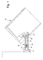
- FIGS. 1 and 2 schematically show an orientable lighting appliance comprising a supporting arm 10 which supports and is constrained to at least one projector or lamp space 12 inside which at least one light source is envisaged (not shown).
- the light source contained inside the lamp space 12 can consist for example of a lamp of the discharge type or a halogen lamp, charged at either the supply voltage or at a low voltage by the interposition of a suitable transformer.
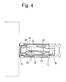
- the lamp space 12 contains in its interior all the elements necessary for the correct functioning of the lighting appliance, i.e. possible reflecting walls and/or shields, reactors, transformers and various electric components, whereas the supporting arm 10, inside which at least one groove 14 is envisaged (figure 4) for the passage of electric supply wires, is suitable for direct fixing to walls or ceilings or on a specific guiding rail or on an analogous structure by means of its connecting portion 16.
- the constraint between the lamp space 12 and the supporting arm 10 is provided by means of a hinge 18 around which the lamp space 12 can be rotated by a user in order to obtain the desired orientation.
- the lamp space 12 and the supporting arm 10 of the lighting appliance are produced in metal, for example in aluminum pressure die-casting, and in a thermoplastic material.
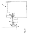
- the lighting appliance is equipped with a rod or lever 20 slidingly coupled with the arm 10 and constrainable thereto, hinged onto the lamp space 12 by means of a pin 22 having a rotation axis parallel and distanced with respect to the rotation axis of the hinge 18 which connects the lamp space 12 to its supporting arm 10.
- the rod 20 On the free end of the rod 20, i.e. the opposite end to that on which the rotation pin 22 is situated, there is an opening 24 capable of receiving in its interior at least one block bead 26, or any other analogous fixing means, whose function is to allow the rod 20 to be constrained to the supporting arm 10 and consequently keep the lamp space 12 in a fixed position with respect to its arm 10 according to a desired tilting, as can be seen for example in the schematized drawings of figures 1 and 2.
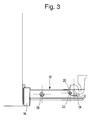
- the rod 20 is situated inside the arm 10, in a position hidden from an outside observer, and its movement with respect to said arm 10 is made possible by the fact that the rod 20 itself slides inside a specific guide channel defined by one or more opposite guiding walls 28 and 30 situated in the body of the arm 10.
- the opening 24 can be dimensioned so as to allow a predefined translation movement of the rod 20 inside the arm 10 thus allowing the projector 12 to rotate according to a pre-established width angle, for example up to 80°-90°.
- the block bead 26 cooperates both with the wall 28, engaging and disengaging the rod 20 to select and maintain a certain position of the projector 12 which rotates around its own hinge 18, and also with the opening 24, to define a run-end with the two opposite ends of the opening 24, which defines the two extreme positions which the projector 12 and have with respect to the supporting arm 10.
- the supporting arm 10 can also be equipped with a top or closing casing 32 which allows access and inspection of the rod 20, of the hinge 18 and rotation pin 22, in addition to the supply wires of the light source. If said top 32 is present, the bead 26 can also have the function of blocking the top 32 of the arm 10.
- the top 32 has a suitable internal protuberance equipped with an opening (not shown), suitable for being inserted in a corresponding groove 34, envisaged on the arm 10 in correspondence with the wall 28, when the top itself 32 is assembled in position, so that the bead 26, by introducing it into the above opening, exerts the double function of being engaged with the rod 20 and blocking the top 32 on the supporting arm 10.
- the supporting arm 10 can be produced in a single piece, whereas the rod 20 can also optionally be situated outside the arm 10, maintaining however the same functional characteristics.
- the projector 12 is rotated around the hinge 18 which constrains it to the supporting arm 10. This rotation simultaneously also causes the rototranslation of the pin 22 with respect to the axis of the fixed hinge 18 and the consequent movement of the rod 20 inside the arm 10.
- the rototranslation movement of the rod 20 is blocked by fixing the block bead 26 so that, thanks to the screwing force applied on the threadings of the hole situated on the arm 10, the block bead itself 26 compresses the rod 20 against the guiding wall 28, thus constraining said rod 20 to the body of the arm 10. In this way, the projector 12 is kept firmly in position preventing any accidental movement with respect to the supporting arm 10.
- the orientable lighting appliance which can be installed on walls or ceilings, according to the present invention, achieves the objectives indicated above, as it allows the projector to be blocked in position and rapidly unblocked to be re-oriented by simply acting on the block bead, easily accessible from the outside but not at all cumbersome and with an extremely reduced visible impact, which controls the position of the translatable rod with respect to the supporting arm.
- the orientable lighting appliance according to the present invention thus conceived can undergo numerous modifications and variants, all included in the same innovative concept; furthermore all the details can be substituted by technically equivalent elements.
Landscapes
- Engineering & Computer Science (AREA)
- General Engineering & Computer Science (AREA)
- Architecture (AREA)
- Non-Portable Lighting Devices Or Systems Thereof (AREA)
- Lighting Device Outwards From Vehicle And Optical Signal (AREA)
- Circuit Arrangements For Discharge Lamps (AREA)
- Fastening Of Light Sources Or Lamp Holders (AREA)
Abstract
Description
- The present invention relates to an orientable lighting appliance, suitable in particular but not exclusively for wall installations, having considerable usefulness and convenience of use.
- Lighting appliances are known, which substantially comprise a projector which can be rotated around an arm suitable for wall or ceiling installations. These lighting appliances are normally used for directly and distinctly illuminating a certain target and their particular characteristic is that they can be easily orientated depending on the requirements of use.
- One of the disadvantages of some of the orientable lighting appliances according to the known art, however, is that they do not envisage adequate means for blocking the projector once the desired lighting position has been found. In these appliances, in fact, the blocking is simply due to the friction caused in correspondence with the joining hinge between the arm fixed to the wall and the projector itself, and consequently there is no guarantee of the necessary safety and stability, especially after prolonged use.
- Some lighting appliances therefore envisage specific blocking mechanisms in the position of the projector once it has been oriented as required, but these mechanisms are not only complicated to produce and manoeuvre but also have external activating elements which in some way disturb the aesthetic appearance of the lighting appliance itself.
- An objective of the present invention is therefore to provide an orientable lighting appliance, suitable in particular for direct wall or ceiling installations but also possibly on specific guiding rails, which is capable of eliminating the above drawbacks, simplifying the orientation and making the subsequent blocking of the projector which rotates around its supporting arm, more stable.
- A further objective of the present invention is to provide an orientable lighting appliance with a limited encumbrance, an extremely simple structure and with regulation and blocking elements which are totally or almost invisible for an external observer, and at the same time easy to activate.
- These objectives according to the present invention are achieved by providing an orientable lighting appliance as specified in claim 1.
- Further characteristics of the invention are indicated in the subsequent claims.
- The characteristics and advantages of an orientable lighting appliance according to the present invention will appear more evident from the following illustrative and non-limiting description, referring to the enclosed schematic drawings in which:
- figure 1 is a partial sectional side view of an orientable lighting appliance according to the invention, in a first operative position;
- figure 2 is a partial sectional side view of an orientable lighting appliance of figure 1, in a second operative position;
- figure 3 is a partial sectional side view of the fixing arm of the lighting appliance of figure 1; and
- figure 4 is a partial sectional plan view of the fixing arm of figure 3.
- With reference in particular to figures 1 and 2, these schematically show an orientable lighting appliance comprising a supporting
arm 10 which supports and is constrained to at least one projector orlamp space 12 inside which at least one light source is envisaged (not shown). - The light source contained inside the
lamp space 12 can consist for example of a lamp of the discharge type or a halogen lamp, charged at either the supply voltage or at a low voltage by the interposition of a suitable transformer. - In addition to the light source, the
lamp space 12 contains in its interior all the elements necessary for the correct functioning of the lighting appliance, i.e. possible reflecting walls and/or shields, reactors, transformers and various electric components, whereas the supportingarm 10, inside which at least onegroove 14 is envisaged (figure 4) for the passage of electric supply wires, is suitable for direct fixing to walls or ceilings or on a specific guiding rail or on an analogous structure by means of its connectingportion 16. - More specifically, the constraint between the
lamp space 12 and the supportingarm 10 is provided by means of ahinge 18 around which thelamp space 12 can be rotated by a user in order to obtain the desired orientation. On the basis of a preferred embodiment, thelamp space 12 and the supportingarm 10 of the lighting appliance are produced in metal, for example in aluminum pressure die-casting, and in a thermoplastic material. - According to the present invention, the lighting appliance is equipped with a rod or
lever 20 slidingly coupled with thearm 10 and constrainable thereto, hinged onto thelamp space 12 by means of apin 22 having a rotation axis parallel and distanced with respect to the rotation axis of thehinge 18 which connects thelamp space 12 to its supportingarm 10. - On the free end of the
rod 20, i.e. the opposite end to that on which therotation pin 22 is situated, there is an opening 24 capable of receiving in its interior at least oneblock bead 26, or any other analogous fixing means, whose function is to allow therod 20 to be constrained to the supportingarm 10 and consequently keep thelamp space 12 in a fixed position with respect to itsarm 10 according to a desired tilting, as can be seen for example in the schematized drawings of figures 1 and 2. - More specifically, according to the preferred embodiment illustrated in the enclosed drawings, the
rod 20 is situated inside thearm 10, in a position hidden from an outside observer, and its movement with respect to saidarm 10 is made possible by the fact that therod 20 itself slides inside a specific guide channel defined by one or more opposite guidingwalls arm 10. On at least one of said guidingwalls block bead 26 so that its visible end can be operated manually or by means of a specific tool for effecting the blocking and unblocking of therod 20 with respect to thearm 10 of the lighting appliance, as better described hereunder. - The opening 24 can be dimensioned so as to allow a predefined translation movement of the
rod 20 inside thearm 10 thus allowing theprojector 12 to rotate according to a pre-established width angle, for example up to 80°-90°. In short, theblock bead 26 cooperates both with thewall 28, engaging and disengaging therod 20 to select and maintain a certain position of theprojector 12 which rotates around itsown hinge 18, and also with the opening 24, to define a run-end with the two opposite ends of the opening 24, which defines the two extreme positions which theprojector 12 and have with respect to the supportingarm 10. - The supporting
arm 10 can also be equipped with a top orclosing casing 32 which allows access and inspection of therod 20, of thehinge 18 androtation pin 22, in addition to the supply wires of the light source. If saidtop 32 is present, thebead 26 can also have the function of blocking thetop 32 of thearm 10. - In particular, the
top 32 has a suitable internal protuberance equipped with an opening (not shown), suitable for being inserted in acorresponding groove 34, envisaged on thearm 10 in correspondence with thewall 28, when the top itself 32 is assembled in position, so that thebead 26, by introducing it into the above opening, exerts the double function of being engaged with therod 20 and blocking thetop 32 on the supportingarm 10. - Alternatively, the supporting
arm 10 can be produced in a single piece, whereas therod 20 can also optionally be situated outside thearm 10, maintaining however the same functional characteristics. - From an operative point of view, in order to proceed with the orientation of the
projector 12, once it has been verified that theblock bead 26 is not completely fixed, theprojector 12 is rotated around thehinge 18 which constrains it to the supportingarm 10. This rotation simultaneously also causes the rototranslation of thepin 22 with respect to the axis of thefixed hinge 18 and the consequent movement of therod 20 inside thearm 10. - Once the desired position of the
projector 12 has been reached, the rototranslation movement of therod 20 is blocked by fixing theblock bead 26 so that, thanks to the screwing force applied on the threadings of the hole situated on thearm 10, the block bead itself 26 compresses therod 20 against theguiding wall 28, thus constraining saidrod 20 to the body of thearm 10. In this way, theprojector 12 is kept firmly in position preventing any accidental movement with respect to the supportingarm 10. - Vice versa, again by simply acting on the
block bead 26, in this case by partially unscrewing it, therod 20 is disengaged from thearm 10, thus allowing theprojector 12 to be repositioned as desired. - It can therefore be seen that the orientable lighting appliance, which can be installed on walls or ceilings, according to the present invention, achieves the objectives indicated above, as it allows the projector to be blocked in position and rapidly unblocked to be re-oriented by simply acting on the block bead, easily accessible from the outside but not at all cumbersome and with an extremely reduced visible impact, which controls the position of the translatable rod with respect to the supporting arm.
- The orientable lighting appliance according to the present invention thus conceived can undergo numerous modifications and variants, all included in the same innovative concept; furthermore all the details can be substituted by technically equivalent elements.
- In practice, the materials used, as also the dimensions, can vary according to technical demands.
Claims (9)
- An orientable lighting appliance of the type comprising a supporting arm (10), suitable for installation on a fixed structure, which supports, by means of a hinge (18), at least one lamp space (12) inside which there is at least one light source, characterized in that it comprises at least one lever (20) slidingly coupled with the supporting arm (10) and constrainable thereto, said lever (20) being hinged on said lamp space (12) by means of a pin (22) having a parallel and distanced rotation axis with respect to the rotation axis of the hinge (18).
- The lighting appliance according to claim 1, characterized in that said lever (20) is situated inside said supporting arm (10) and slides inside a specific guiding channel defined by one or more opposite guiding walls (28) and (30) situated in the body of said supporting arm (10).
- The lighting appliance according to claim 2, characterized in that said lever (20) can be constrained to said supporting arm (10) by means of at least one threaded fixing element (26) inserted in a corresponding threaded hole situated in at least one of said one or more opposite guiding walls (28) and (30).
- The lighting appliance according to claim 3, characterized in that on the end of said lever (20) opposite to that on which said pin (22) is situated, there is an opening (24) capable of housing in its interior said at least one threaded fixing element (26) to compress said lever (20) against said wall (28) and constrain said lever (20) to said supporting arm (10).
- The lighting appliance according to claim 3, characterized in that said at least one threaded fixing element (26) consists of a block bead which can be operated manually or by means of a specific tool.
- The lighting appliance according to claim 2, characterized in that said supporting arm (10) is equipped with a top (32) which allows access to and the inspection of the lever (20), the hinge (18) and the pin (22), in addition to the supply wires of said light source.
- The lighting appliance according to claim 6, characterized in that said top (32) has an internal protuberance equipped with an opening suitable for being inserted in a corresponding groove (34) envisaged on the supporting arm (10) in correspondence with the wall (28) when said top (32) is assembled in position, said threaded fixing element (26) being introduced into said opening to block the top (32) on said supporting arm (10).
- The lighting appliance according to any of the claims from 1 to 7, characterized in that said lamp space (12), said supporting arm (10) and said lever (20) are made of metal.
- The lighting appliance according to any of the claims from 1 to 7, characterized in that said lamp space (12), said supporting arm (10) and said lever (20) are made of a plastic material.
Applications Claiming Priority (1)
| Application Number | Priority Date | Filing Date | Title |
|---|---|---|---|
| IT000166U ITMI20060166U1 (en) | 2006-05-09 | 2006-05-09 | APPARATUS OF ADJUSTABLE LIGHTING |
Publications (2)
| Publication Number | Publication Date |
|---|---|
| EP1855049A1 true EP1855049A1 (en) | 2007-11-14 |
| EP1855049B1 EP1855049B1 (en) | 2011-06-29 |
Family
ID=38220415
Family Applications (1)
| Application Number | Title | Priority Date | Filing Date |
|---|---|---|---|
| EP07107321A Active EP1855049B1 (en) | 2006-05-09 | 2007-05-02 | Orientable Lighting Appliance |
Country Status (6)
| Country | Link |
|---|---|
| EP (1) | EP1855049B1 (en) |
| CN (1) | CN101070953B (en) |
| AT (1) | ATE514893T1 (en) |
| ES (1) | ES2368790T3 (en) |
| IT (1) | ITMI20060166U1 (en) |
| NO (1) | NO20072338L (en) |
Cited By (2)
| Publication number | Priority date | Publication date | Assignee | Title |
|---|---|---|---|---|
| ITVI20080179A1 (en) * | 2008-07-28 | 2010-01-29 | Tekno System S P A | STRUCTURE ILLUMINATED DEVICE FOR VIDEO-SURVEILLANCE SYSTEMS. |
| US8256925B2 (en) | 2010-03-02 | 2012-09-04 | Hong Fu Jin Precision Industry (Shenzhen) Co., Ltd. | Rotatory table lamp |
Families Citing this family (3)
| Publication number | Priority date | Publication date | Assignee | Title |
|---|---|---|---|---|
| CN101463977B (en) * | 2007-12-21 | 2010-06-02 | 富准精密工业(深圳)有限公司 | LED lamp |
| US7780318B2 (en) | 2008-02-01 | 2010-08-24 | Fu Zhun Precision Industry (Shen Zhen) Co., Ltd. | Flood lamp assembly having a reinforced bracket for supporting a weight thereof |
| CN104344369B (en) * | 2013-07-26 | 2018-09-11 | 海洋王(东莞)照明科技有限公司 | Holder and the lamps and lanterns for using the holder |
Citations (3)
| Publication number | Priority date | Publication date | Assignee | Title |
|---|---|---|---|---|
| US20030076677A1 (en) * | 2001-10-23 | 2003-04-24 | Ferenc Mohacsi | Lamp |
| US20030227772A1 (en) | 2002-06-05 | 2003-12-11 | Yoshida Michael K. | Indirector light Fixture |
| EP1477725A2 (en) | 2003-05-13 | 2004-11-17 | TRILUX-LENZE GmbH + Co. KG | Wall-mounted luminaire |
Family Cites Families (2)
| Publication number | Priority date | Publication date | Assignee | Title |
|---|---|---|---|---|
| ITMI20040172U1 (en) * | 2004-04-15 | 2004-07-15 | Iguzzini Illuminazione | REFLECTIVE SURFACE REFLECTIVE ASSEMBLY MODIFIABLE IN A LIGHTING DEVICE |
| ITMI20040201U1 (en) * | 2004-04-30 | 2004-07-30 | Iguzzini Illuminazione | SEMI-RECESSED CONCENTRATED BEAM LIGHTING LUMINAIRE |
-
2006
- 2006-05-09 IT IT000166U patent/ITMI20060166U1/en unknown
-
2007
- 2007-05-02 EP EP07107321A patent/EP1855049B1/en active Active
- 2007-05-02 ES ES07107321T patent/ES2368790T3/en active Active
- 2007-05-02 AT AT07107321T patent/ATE514893T1/en not_active IP Right Cessation
- 2007-05-07 NO NO20072338A patent/NO20072338L/en not_active Application Discontinuation
- 2007-05-08 CN CN2007101024319A patent/CN101070953B/en active Active
Patent Citations (3)
| Publication number | Priority date | Publication date | Assignee | Title |
|---|---|---|---|---|
| US20030076677A1 (en) * | 2001-10-23 | 2003-04-24 | Ferenc Mohacsi | Lamp |
| US20030227772A1 (en) | 2002-06-05 | 2003-12-11 | Yoshida Michael K. | Indirector light Fixture |
| EP1477725A2 (en) | 2003-05-13 | 2004-11-17 | TRILUX-LENZE GmbH + Co. KG | Wall-mounted luminaire |
Cited By (2)
| Publication number | Priority date | Publication date | Assignee | Title |
|---|---|---|---|---|
| ITVI20080179A1 (en) * | 2008-07-28 | 2010-01-29 | Tekno System S P A | STRUCTURE ILLUMINATED DEVICE FOR VIDEO-SURVEILLANCE SYSTEMS. |
| US8256925B2 (en) | 2010-03-02 | 2012-09-04 | Hong Fu Jin Precision Industry (Shenzhen) Co., Ltd. | Rotatory table lamp |
Also Published As
| Publication number | Publication date |
|---|---|
| CN101070953B (en) | 2010-09-08 |
| NO20072338L (en) | 2007-11-12 |
| ATE514893T1 (en) | 2011-07-15 |
| EP1855049B1 (en) | 2011-06-29 |
| ITMI20060166U1 (en) | 2007-11-10 |
| ES2368790T3 (en) | 2011-11-22 |
| CN101070953A (en) | 2007-11-14 |
Similar Documents
| Publication | Publication Date | Title |
|---|---|---|
| EP1855049A1 (en) | Orientable Lighting Appliance | |
| US20170227194A1 (en) | Vandal resistant light fixture | |
| US20230045469A1 (en) | Adjustable and/or Recessed Light Fixtures and Related Components and Methods | |
| US11585500B2 (en) | Lighting fixture having an adjustable optic system | |
| US8777459B2 (en) | Recessed luminaire | |
| JP2012104285A (en) | Task light device | |
| BR0308029A (en) | Household appliance | |
| JP5870390B2 (en) | Guide bracket | |
| EA026436B1 (en) | Pivot hinge for rotational movement of a door, in particular, of a reinforced door | |
| JP2005066122A (en) | Structure of storage body with lighting | |
| US20140268725A1 (en) | System for the distribution of luminance | |
| KR200489639Y1 (en) | Track lighting with easy angle adjustment | |
| KR100982627B1 (en) | A fluorescent lamp reflective plate | |
| US5548500A (en) | Lamp fixture with adjustable lamp socket | |
| WO2011089065A2 (en) | Door leaf system for closing and/or opening an entrance | |
| CN208546935U (en) | It freely adjusts lamp cap and adjusts lamp | |
| JP3774214B2 (en) | Latching lock device | |
| CN214891014U (en) | External lamp | |
| CN210568198U (en) | Optical focusing device | |
| CN208519604U (en) | Combination type LED lamp | |
| KR200436910Y1 (en) | The light which is bought in the wall body | |
| EP1788304A3 (en) | Lighting device | |
| JP2006191889A (en) | Lifting mechanism of lighting apparatus for aquarium | |
| KR200305040Y1 (en) | Lighting apparatus for providing with safety apparatus and cold-proof in low temperature | |
| KR0119956Y1 (en) | Cover fixing construction of a fluorescent lamp |
Legal Events
| Date | Code | Title | Description |
|---|---|---|---|
| PUAI | Public reference made under article 153(3) epc to a published international application that has entered the european phase |
Free format text: ORIGINAL CODE: 0009012 |
|
| AK | Designated contracting states |
Kind code of ref document: A1 Designated state(s): AT BE BG CH CY CZ DE DK EE ES FI FR GB GR HU IE IS IT LI LT LU LV MC MT NL PL PT RO SE SI SK TR |
|
| AX | Request for extension of the european patent |
Extension state: AL BA HR MK YU |
|
| 17P | Request for examination filed |
Effective date: 20080320 |
|
| AKX | Designation fees paid |
Designated state(s): AT BE BG CH CY CZ DE DK EE ES FI FR GB GR HU IE IS IT LI LT LU LV MC MT NL PL PT RO SE SI SK TR |
|
| GRAP | Despatch of communication of intention to grant a patent |
Free format text: ORIGINAL CODE: EPIDOSNIGR1 |
|
| GRAS | Grant fee paid |
Free format text: ORIGINAL CODE: EPIDOSNIGR3 |
|
| GRAA | (expected) grant |
Free format text: ORIGINAL CODE: 0009210 |
|
| AK | Designated contracting states |
Kind code of ref document: B1 Designated state(s): AT BE BG CH CY CZ DE DK EE ES FI FR GB GR HU IE IS IT LI LT LU LV MC MT NL PL PT RO SE SI SK TR |
|
| REG | Reference to a national code |
Ref country code: GB Ref legal event code: FG4D |
|
| REG | Reference to a national code |
Ref country code: CH Ref legal event code: EP |
|
| REG | Reference to a national code |
Ref country code: IE Ref legal event code: FG4D |
|
| REG | Reference to a national code |
Ref country code: DE Ref legal event code: R096 Ref document number: 602007015476 Country of ref document: DE Effective date: 20110818 |
|
| REG | Reference to a national code |
Ref country code: NL Ref legal event code: VDEP Effective date: 20110629 |
|
| PG25 | Lapsed in a contracting state [announced via postgrant information from national office to epo] |
Ref country code: LT Free format text: LAPSE BECAUSE OF FAILURE TO SUBMIT A TRANSLATION OF THE DESCRIPTION OR TO PAY THE FEE WITHIN THE PRESCRIBED TIME-LIMIT Effective date: 20110629 Ref country code: SE Free format text: LAPSE BECAUSE OF FAILURE TO SUBMIT A TRANSLATION OF THE DESCRIPTION OR TO PAY THE FEE WITHIN THE PRESCRIBED TIME-LIMIT Effective date: 20110629 |
|
| REG | Reference to a national code |
Ref country code: ES Ref legal event code: FG2A Ref document number: 2368790 Country of ref document: ES Kind code of ref document: T3 Effective date: 20111122 |
|
| PG25 | Lapsed in a contracting state [announced via postgrant information from national office to epo] |
Ref country code: LV Free format text: LAPSE BECAUSE OF FAILURE TO SUBMIT A TRANSLATION OF THE DESCRIPTION OR TO PAY THE FEE WITHIN THE PRESCRIBED TIME-LIMIT Effective date: 20110629 Ref country code: AT Free format text: LAPSE BECAUSE OF FAILURE TO SUBMIT A TRANSLATION OF THE DESCRIPTION OR TO PAY THE FEE WITHIN THE PRESCRIBED TIME-LIMIT Effective date: 20110629 Ref country code: FI Free format text: LAPSE BECAUSE OF FAILURE TO SUBMIT A TRANSLATION OF THE DESCRIPTION OR TO PAY THE FEE WITHIN THE PRESCRIBED TIME-LIMIT Effective date: 20110629 Ref country code: SI Free format text: LAPSE BECAUSE OF FAILURE TO SUBMIT A TRANSLATION OF THE DESCRIPTION OR TO PAY THE FEE WITHIN THE PRESCRIBED TIME-LIMIT Effective date: 20110629 Ref country code: GR Free format text: LAPSE BECAUSE OF FAILURE TO SUBMIT A TRANSLATION OF THE DESCRIPTION OR TO PAY THE FEE WITHIN THE PRESCRIBED TIME-LIMIT Effective date: 20110930 |
|
| PG25 | Lapsed in a contracting state [announced via postgrant information from national office to epo] |
Ref country code: BE Free format text: LAPSE BECAUSE OF FAILURE TO SUBMIT A TRANSLATION OF THE DESCRIPTION OR TO PAY THE FEE WITHIN THE PRESCRIBED TIME-LIMIT Effective date: 20110629 |
|
| PG25 | Lapsed in a contracting state [announced via postgrant information from national office to epo] |
Ref country code: NL Free format text: LAPSE BECAUSE OF FAILURE TO SUBMIT A TRANSLATION OF THE DESCRIPTION OR TO PAY THE FEE WITHIN THE PRESCRIBED TIME-LIMIT Effective date: 20110629 Ref country code: PT Free format text: LAPSE BECAUSE OF FAILURE TO SUBMIT A TRANSLATION OF THE DESCRIPTION OR TO PAY THE FEE WITHIN THE PRESCRIBED TIME-LIMIT Effective date: 20111031 Ref country code: CZ Free format text: LAPSE BECAUSE OF FAILURE TO SUBMIT A TRANSLATION OF THE DESCRIPTION OR TO PAY THE FEE WITHIN THE PRESCRIBED TIME-LIMIT Effective date: 20110629 Ref country code: IS Free format text: LAPSE BECAUSE OF FAILURE TO SUBMIT A TRANSLATION OF THE DESCRIPTION OR TO PAY THE FEE WITHIN THE PRESCRIBED TIME-LIMIT Effective date: 20111029 Ref country code: EE Free format text: LAPSE BECAUSE OF FAILURE TO SUBMIT A TRANSLATION OF THE DESCRIPTION OR TO PAY THE FEE WITHIN THE PRESCRIBED TIME-LIMIT Effective date: 20110629 |
|
| PG25 | Lapsed in a contracting state [announced via postgrant information from national office to epo] |
Ref country code: SK Free format text: LAPSE BECAUSE OF FAILURE TO SUBMIT A TRANSLATION OF THE DESCRIPTION OR TO PAY THE FEE WITHIN THE PRESCRIBED TIME-LIMIT Effective date: 20110629 Ref country code: PL Free format text: LAPSE BECAUSE OF FAILURE TO SUBMIT A TRANSLATION OF THE DESCRIPTION OR TO PAY THE FEE WITHIN THE PRESCRIBED TIME-LIMIT Effective date: 20110629 Ref country code: CY Free format text: LAPSE BECAUSE OF FAILURE TO SUBMIT A TRANSLATION OF THE DESCRIPTION OR TO PAY THE FEE WITHIN THE PRESCRIBED TIME-LIMIT Effective date: 20110629 Ref country code: RO Free format text: LAPSE BECAUSE OF FAILURE TO SUBMIT A TRANSLATION OF THE DESCRIPTION OR TO PAY THE FEE WITHIN THE PRESCRIBED TIME-LIMIT Effective date: 20110629 |
|
| PLBE | No opposition filed within time limit |
Free format text: ORIGINAL CODE: 0009261 |
|
| STAA | Information on the status of an ep patent application or granted ep patent |
Free format text: STATUS: NO OPPOSITION FILED WITHIN TIME LIMIT |
|
| 26N | No opposition filed |
Effective date: 20120330 |
|
| PG25 | Lapsed in a contracting state [announced via postgrant information from national office to epo] |
Ref country code: DK Free format text: LAPSE BECAUSE OF FAILURE TO SUBMIT A TRANSLATION OF THE DESCRIPTION OR TO PAY THE FEE WITHIN THE PRESCRIBED TIME-LIMIT Effective date: 20110629 |
|
| REG | Reference to a national code |
Ref country code: DE Ref legal event code: R097 Ref document number: 602007015476 Country of ref document: DE Effective date: 20120330 |
|
| PG25 | Lapsed in a contracting state [announced via postgrant information from national office to epo] |
Ref country code: MC Free format text: LAPSE BECAUSE OF NON-PAYMENT OF DUE FEES Effective date: 20120531 |
|
| REG | Reference to a national code |
Ref country code: CH Ref legal event code: PL |
|
| PG25 | Lapsed in a contracting state [announced via postgrant information from national office to epo] |
Ref country code: LI Free format text: LAPSE BECAUSE OF NON-PAYMENT OF DUE FEES Effective date: 20120531 Ref country code: CH Free format text: LAPSE BECAUSE OF NON-PAYMENT OF DUE FEES Effective date: 20120531 |
|
| REG | Reference to a national code |
Ref country code: IE Ref legal event code: MM4A |
|
| PG25 | Lapsed in a contracting state [announced via postgrant information from national office to epo] |
Ref country code: IE Free format text: LAPSE BECAUSE OF NON-PAYMENT OF DUE FEES Effective date: 20120502 |
|
| PG25 | Lapsed in a contracting state [announced via postgrant information from national office to epo] |
Ref country code: BG Free format text: LAPSE BECAUSE OF FAILURE TO SUBMIT A TRANSLATION OF THE DESCRIPTION OR TO PAY THE FEE WITHIN THE PRESCRIBED TIME-LIMIT Effective date: 20110929 |
|
| PG25 | Lapsed in a contracting state [announced via postgrant information from national office to epo] |
Ref country code: MT Free format text: LAPSE BECAUSE OF FAILURE TO SUBMIT A TRANSLATION OF THE DESCRIPTION OR TO PAY THE FEE WITHIN THE PRESCRIBED TIME-LIMIT Effective date: 20110629 |
|
| PG25 | Lapsed in a contracting state [announced via postgrant information from national office to epo] |
Ref country code: TR Free format text: LAPSE BECAUSE OF FAILURE TO SUBMIT A TRANSLATION OF THE DESCRIPTION OR TO PAY THE FEE WITHIN THE PRESCRIBED TIME-LIMIT Effective date: 20110629 |
|
| PG25 | Lapsed in a contracting state [announced via postgrant information from national office to epo] |
Ref country code: LU Free format text: LAPSE BECAUSE OF NON-PAYMENT OF DUE FEES Effective date: 20120502 |
|
| PG25 | Lapsed in a contracting state [announced via postgrant information from national office to epo] |
Ref country code: HU Free format text: LAPSE BECAUSE OF FAILURE TO SUBMIT A TRANSLATION OF THE DESCRIPTION OR TO PAY THE FEE WITHIN THE PRESCRIBED TIME-LIMIT Effective date: 20070502 |
|
| REG | Reference to a national code |
Ref country code: FR Ref legal event code: PLFP Year of fee payment: 10 |
|
| REG | Reference to a national code |
Ref country code: FR Ref legal event code: PLFP Year of fee payment: 11 |
|
| REG | Reference to a national code |
Ref country code: FR Ref legal event code: PLFP Year of fee payment: 12 |
|
| P01 | Opt-out of the competence of the unified patent court (upc) registered |
Effective date: 20230525 |
|
| PGFP | Annual fee paid to national office [announced via postgrant information from national office to epo] |
Ref country code: IT Payment date: 20230529 Year of fee payment: 17 Ref country code: FR Payment date: 20230510 Year of fee payment: 17 Ref country code: ES Payment date: 20230605 Year of fee payment: 17 Ref country code: DE Payment date: 20230502 Year of fee payment: 17 |
|
| PGFP | Annual fee paid to national office [announced via postgrant information from national office to epo] |
Ref country code: GB Payment date: 20230504 Year of fee payment: 17 |