EP1873871A2 - Electrical connector - Google Patents
Electrical connector Download PDFInfo
- Publication number
- EP1873871A2 EP1873871A2 EP07012379A EP07012379A EP1873871A2 EP 1873871 A2 EP1873871 A2 EP 1873871A2 EP 07012379 A EP07012379 A EP 07012379A EP 07012379 A EP07012379 A EP 07012379A EP 1873871 A2 EP1873871 A2 EP 1873871A2
- Authority
- EP
- European Patent Office
- Prior art keywords
- circumferential surface
- wire
- mounting portion
- holder
- outer circumferential
- Prior art date
- Legal status (The legal status is an assumption and is not a legal conclusion. Google has not performed a legal analysis and makes no representation as to the accuracy of the status listed.)
- Granted
Links
Images


Classifications
-
- H—ELECTRICITY
- H01—ELECTRIC ELEMENTS
- H01R—ELECTRICALLY-CONDUCTIVE CONNECTIONS; STRUCTURAL ASSOCIATIONS OF A PLURALITY OF MUTUALLY-INSULATED ELECTRICAL CONNECTING ELEMENTS; COUPLING DEVICES; CURRENT COLLECTORS
- H01R13/00—Details of coupling devices of the kinds covered by groups H01R12/70 or H01R24/00 - H01R33/00
- H01R13/62—Means for facilitating engagement or disengagement of coupling parts or for holding them in engagement
- H01R13/639—Additional means for holding or locking coupling parts together, after engagement, e.g. separate keylock, retainer strap
-
- H—ELECTRICITY
- H01—ELECTRIC ELEMENTS
- H01R—ELECTRICALLY-CONDUCTIVE CONNECTIONS; STRUCTURAL ASSOCIATIONS OF A PLURALITY OF MUTUALLY-INSULATED ELECTRICAL CONNECTING ELEMENTS; COUPLING DEVICES; CURRENT COLLECTORS
- H01R13/00—Details of coupling devices of the kinds covered by groups H01R12/70 or H01R24/00 - H01R33/00
- H01R13/46—Bases; Cases
- H01R13/52—Dustproof, splashproof, drip-proof, waterproof, or flameproof cases
- H01R13/5205—Sealing means between cable and housing, e.g. grommet
- H01R13/5208—Sealing means between cable and housing, e.g. grommet having at least two cable receiving openings
-
- H—ELECTRICITY
- H01—ELECTRIC ELEMENTS
- H01R—ELECTRICALLY-CONDUCTIVE CONNECTIONS; STRUCTURAL ASSOCIATIONS OF A PLURALITY OF MUTUALLY-INSULATED ELECTRICAL CONNECTING ELEMENTS; COUPLING DEVICES; CURRENT COLLECTORS
- H01R13/00—Details of coupling devices of the kinds covered by groups H01R12/70 or H01R24/00 - H01R33/00
- H01R13/46—Bases; Cases
- H01R13/502—Bases; Cases composed of different pieces
- H01R13/506—Bases; Cases composed of different pieces assembled by snap action of the parts
-
- H—ELECTRICITY
- H01—ELECTRIC ELEMENTS
- H01R—ELECTRICALLY-CONDUCTIVE CONNECTIONS; STRUCTURAL ASSOCIATIONS OF A PLURALITY OF MUTUALLY-INSULATED ELECTRICAL CONNECTING ELEMENTS; COUPLING DEVICES; CURRENT COLLECTORS
- H01R13/00—Details of coupling devices of the kinds covered by groups H01R12/70 or H01R24/00 - H01R33/00
- H01R13/62—Means for facilitating engagement or disengagement of coupling parts or for holding them in engagement
- H01R13/627—Snap or like fastening
- H01R13/6271—Latching means integral with the housing
- H01R13/6272—Latching means integral with the housing comprising a single latching arm
Definitions
- the present invention relates to a connector.
- a known connector is provided with a connector housing for accommodating a terminal fitting connected with an end of a wire, a sealing member mounted on the wire and fitted into an opening portion at the rear end of the connector housing, and a rear holder mounted on the connector housing from behind to press and retain the sealing member (see, for example, Japanese Unexamined Patent Publication No. 2004-171831 ).
- the rear holder is formed with a wire insertion hole through which the wire is passed, and the wire is drawn out to the outside through this wire insertion hole. Further, this rear holder is formed with a resiliently deformable locking piece engageable with an engaging portion provided on the circumferential surface of the connector housing. When the rear holder is properly mounted on the connector housing, the locking piece is resiliently engaged with the engaging portion to retain the rear holder on the connector housing.
- a terminal fitting connected with an end of a wire is inserted and held in a cavity of a connector housing, and a rubber plug is mounted on the end of the wire.
- a tubular mounting portion is so formed at a rear part of the connector housing as to have an open rear surface, and the rubber plug is held in close contact with the inner circumferential surface of the mounting portion.
- a cap-shaped rear holder for pressing the rubber plug from behind to retain the rubber plug is mounted on the rear part of the connector housing.
- a back wall of the rear holder is formed with a wire insertion hole through which the wire is inserted.
- the rear holder is formed with a resiliently deformable locking piece, and the rear holder is fixed to the connector housing by the mutual engagement of this locking piece with an interlocking portion projecting from the connector housing.
- the present invention was developed in view of the above situation and an object thereof is to improve the overall operability of the connector, particularly by improving the connection reliability of a terminal fitting and/or by preventing a rear holder from being inadvertently detached from a mounting portion.
- a connector comprising:
- the shake preventing portion of the sealing member mounted on this wire comes substantially into close contact with the outer circumferential surface of the wire and the inner circumferential surface of the wire insertion hole of the holder, thereby suppressing the shake of the wire in the connector housing.
- relative sliding movements of the terminal fitting connected with the end of this wire and a mating terminal fitting can be avoided.
- connected positions of both terminal fittings can be kept substantially constant to improve connection reliability.
- a clearance present between the wire insertion hole and the wire is at least partly filled up by the sealing member.
- a connector comprising:
- the holder (preferably the rear holder) is formed with a substantially tubular portion having the wire insertion hole inside and projecting substantially backward, and the shake preventing portion is held substantially in close contact with the inner circumferential surface of the wire insertion hole in the tubular portion.
- the rear holder is formed with the substantially tubular portion having the wire insertion hole inside and projecting substantially backward and the shake preventing portion is held substantially in close contact with the inner circumferential surface of the wire insertion hole in the tubular portion, the wire is held in contact with the tubular portion over the substantially entire length range of the tubular portion, wherefore the shake of the wire in the connector housing can be reliably suppressed.
- the inner circumferential surface of the wire insertion hole in the tubular portion is tapered toward the rear end of the tubular portion, and the outer circumferential surface of the shake preventing portion is tapered substantially in conformity with the inner surface of the wire insertion hole.
- the inner circumferential surface of the wire insertion hole in the tubular portion is tapered toward the rear end of the tubular portion and the outer circumferential surface of the shake preventing portion is tapered substantially in conformity with the inner surface of the wire insertion hole, if the wire drawn out of the wire insertion hole of the tubular portion is shaken, a shake supporting portion thereof is closely held by the shake preventing portion to suppress the shaking movement. Therefore, a shaking force of the wire is more unlikely to be transmitted to the connected parts of the both terminal fittings, thereby further improving the connection reliability.
- the seal main body is formed to have such a thickness as to substantially fill up a space present between the outer circumferential surface of the wire and the inner circumferential surface of the mounting portion and/or has one or more lips formed on the inner and/or outer circumferential surfaces thereof.
- the shake preventing portion has substantially flat inner and/or outer circumferential surfaces.
- a connector in particular according to the above aspect of the invention or a preferred embodiment thereof, comprising:
- the at least one leading-end widened rib having the leading end wider than the base end or substantially having a dovetail-shape or being undercut is provided on either one of the inner circumferential surface of the surrounding wall of the rear holder and the outer circumferential surface of the mounting portion, the recess is formed in the other surface, and these leading-end widened rib and recess provide the dovetail engagement or a positive joint or a form closure when the holder is mounted. This can prevent the holder from being detached from the connector housing even if the wire is shaken or the entire connector receives certain vibration.
- a connector comprising:
- the leading-end widened rib having the leading end wider than the base end is provided on either one of the inner circumferential surface of the surrounding wall of the rear holder and the outer circumferential surface of the mounting portion, the recess is formed in the other surface, and these leading-end widened rib and recess provide the dovetail engagement when the rear holder is mounted. This can prevent the rear holder from being detached from the connector housing even if the wire is shaken or the entire connector receives certain vibration.
- the one provided at the inner circumferential surface of the surrounding wall of the holder extends substantially up to the back wall of the holder (preferably the rear holder).
- the surrounding wall of the holder (preferably the rear holder) has a substantially cylindrical shape
- the leading-end widened rib is provided on the inner circumferential surface of the surrounding wall
- at least one recessed groove is formed in the outer circumferential surface of the surrounding wall at a position substantially having a back-to-back relationship (or being substantially radially aligned) with the leading-end widened rib.
- the (rear) holder is not distinguishable in circumferential direction when the surrounding wall of the (rear) holder has a cylindrical shape, there is a possibility that it becomes difficult to align the leading-end widened rib provided on the inner circumferential surface of the surrounding wall and the recess to a targeted position, making it difficult to mount the (rear) holder on the mounting portion.
- the recessed groove is formed in the outer circumferential surface of the surrounding wall at the position having the back-to-back relationship with the leading-end widened rib formed on the inner circumferential surface of the surrounding wall.
- the leading-end widened rib can be engaged with the recess using the recessed groove as a marker by positioning this recessed groove and the recess formed in the outer circumferential surface of the mounting portion relative to each other.
- the (rear) holder can be precisely mounted on the mounting portion with good operability.
- the recessed groove at the position substantially corresponding to the leading-end widened rib, an increase in the thickness of the surrounding wall can be suppressed to prevent an occurrence of a surface sink even if the leading-end widened rib is provided.
- an undesirable situation where the leading-end widened rib is broken by getting caught by an external matter can be avoided.
- the mounting portion has a substantially tubular shape having an open rear surface, and/or the back wall of the holder (preferably the rear holder) includes an inner fitting portion to be at least partly fitted into the mounting portion while holding the mounting portion in thickness direction together with the surrounding wall.
- the mounting portion of the (rear) holder When the inner fitting portion of the (rear) holder is fitted into the mounting portion of the connector housing, the mounting portion is held between the inner fitting portion and the surrounding wall in thickness direction and the outer circumferential surface of the inner fitting portion is held substantially in close contact with the inner circumferential surface of the mounting portion.
- the inner fitting portion is kept closely fitted in the mounting portion, whereby the detachment of the (rear) holder from the connector housing can be more reliably prevented.
- a connector F is provided with a female housing 10 (corresponding to a preferred connector housing) for at least partly accommodating a female terminal fitting 30 and a rear holder 50 (as a preferred holder) to be mounted on this female housing 10 from a mounting side MS, preferably substantially from behind or from a side substantially opposite to a mating side with a mating connector, wherein the female housing 10 is connectable with a mating male housing 90.
- the connector F is further provided with a sealing member 98 for providing fluid- or waterproof sealing between the female housing 10 and the terminal fitting 30, and a seal ring 97 for providing fluid- or waterproof sealing between the female and male housings 10 and 90.
- sides of the female and male housings 10, 90 to be connected are referred to as front sides concerning forward and backward directions FBD and reference is made to FIG. 1 concerning vertical direction.
- the mating male housing 90 is made e.g. of a synthetic resin and includes a receptacle 91 preferably substantially in the form of a round tube having an open front side.
- One male tab 92 male terminal fitting
- the male tab 92 preferably is substantially a plate made of an electrically conductive material such as a metal, substantially aligns its plate surface along forward and backward directions FBD, and at least partly projects into the receptacle 91.
- a lock portion 95 projects at a lateral part (preferably an upper end part) of the outer circumferential surface of the receptacle 91.
- the lock portion 95 is resiliently engageable with a lock arm 12 of the female housing 10.
- the female housing 10 is made e.g. of a synthetic resin and, and is provided at or near its front side with a tower portion 13 to be at least partly fitted into the mating receptacle 91 and a fitting tube portion 14 at least partly surrounding the tower portion 13 and defining a space together with the tower portion 13, into which space the receptacle 91 is at least partly inserted or insertable, and at its rear side with a mounting portion 15 (corresponding to a preferred opening portion) which is integrally or unitarily continuous with the tower portion 13 and projects substantially backward and on or to which the rear holder 50 is mounted from the mounting side MS, preferably substantially from behind.
- a mounting portion 15 corresponding to a preferred opening portion
- the mounting portion 15 preferably substantially has a tubular shape, more specifically a round tubular shape and is one size larger than the tower portion 13 while being smaller than the fitting tube portion 14.
- a cavity 16 communicating with the inner space of the mounting portion 15 penetrates or recesses the tower portion 13 substantially in forward and backward directions FBD.
- One terminal fitting 30 is at least partly insertable into the cavity 16 through the inner space of the mounting portion 15 from an insertion side, preferably substantially from behind.
- the terminal fitting 30 is comprised of a (preferably substantially box-shaped) main portion 31 with which the male terminal fitting is connectable, preferably into which the male tab 92 is at least partly insertable, and a wire connection portion (preferably comprising a barrel portion 32) continuous with the rear end of the main portion 31 and to be connected (preferably crimped or bent or folded into connection) with a core of a wire W exposed at an end.
- the main portion 31 is to be at least partly fitted into the cavity 16 of the tower portion 13 preferably while having loose movements thereof substantially prevented, and the barrel portion 32 is arranged in the inner space of the fitting tube portion 14.
- the main portion 31 is formed with a locking hole or recess 33, into which a locking portion 17 provided at the inner wall of the cavity 16 is at least partly fitted to retain the terminal fitting 30 in the cavity 16.
- the sealing member 98 made of resilient material (such as rubber) is to be mounted on the wire W substantially adjacent to or behind the barrel portion 32.
- the sealing member 98 is at least partly inserted into the mounting portion 15 from the mounting side MS, preferably substantially from behind, to be brought substantially into close contact with the inner circumferential surface of the mounting portion 15 and/or the outer circumferential surface of the wire W to provide sealing between these two surfaces.
- the sealing member 98 is also at least partly fitted into the wire insertion hole 55 formed in the rear holder 50, but this is described in detail later.
- a tab insertion opening 13A for permitting the insertion of the male tab 92 is formed in the front surface of the tower portion 13 as a slit substantially extending in a direction at an angle different from 0° or 180°, preferably substantially normal to the forward and backward directions FBD or in width direction, and the front surface of the main portion 31 substantially faces the rear surface of this tab insertion opening 13A.
- a coupling portion 23 is formed to substantially bulge out or project radially outward so as to be substantially continuous with (preferably the rear end of) the fitting tube portion 14.
- the seal ring 97 made of resilient material (such as rubber) is mounted or mountable on the outer circumferential surface of a rear part of the tower portion 13 before the coupling portion 23.
- the seal ring 97 is for coming substantially into close contact with the inner circumferential surface of the receptacle 91 and/or the outer circumferential surface of the tower portion 13 to provide sealing between these two surfaces when the two housings 10, 90 are properly connected.
- the lock arm 12 extends substantially in forward and backward directions FBD at a lateral part (preferably substantially an upper part) of the female housing 10.
- the lock arm 12 is pivotally displaceable like a seesaw (resiliently displaceable) substantially inwardly or outwardly (upward and downward) with a center on a supporting portion 24 provided at a position substantially corresponding to the coupling portion 23.
- a front portion (preferably a front half) of the lock arm 12 is arranged (preferably in a hidden manner) between the fitting tube portion 14 and the tower portion 13, whereas a rear portion (preferably substantially a rear half) thereof is exposed above or outside of the mounting portion 15.
- An operable portion 25 pressed for unlocking is provided at or near the rear end of the lock arm 12 preferably while being slightly elevated.
- An arm accommodating portion 14A bulging preferably to have a substantially gate-shaped cross section is formed at a lateral part (preferably an upper part) of the fitting tube portion 14, and the lock arm 12 is arranged inside this arm accommodating portion 14A.
- An operation window hole 26 used to operate the lock arm 12 is cut out at or near the rear end of the upper wall of the arm accommodating portion 14A.
- the operable portion 25 of the lock arm 12 is or can be operated particularly by the finger or hand of an operator at least partly inserted through the operation window hole 26 for unlocking.
- the lock arm 12 is formed with at least one lock groove 27 extending substantially in forward and backward directions FBD and making an opening at the rear end of the lock arm 12.
- the lock portion 95 is at least partly fitted into the lock groove 27 and engaged with the front end of the lock groove 27, whereby the housings 10, 90 are inseparably locked into each other.
- one or more, preferably a pair of lateral (left and/or right) interlocking portions 34 project from the outer circumferential surface of the mounting portion 15 at an intermediate part (preferably at a substantially middle part) of the mounting portion 15 with respect to forward and backward directions FBD.
- the interlocking portions 34 are resiliently engageable with one or more respective locking pieces 51 provided at the rear holder 50, wherein the mating surfaces (rear surfaces) thereof are slanted guiding surfaces sloped substantially outward or upward toward the front ends and the front surfaces thereof are substantially vertical locking surfaces.
- One or more frame portions 35 are formed at least partly around the interlocking portions 34 in the outer circumferential surface of the mounting portion 15.
- the frame portions 35 are for at least partly surrounding the interlocking portions 34 preferably substantially in U-shape while exposing only rear areas of the interlocking portions 34.
- the frame portions 35 are arranged substantially along the side edges of the locking pieces 51 after the rear holder 50 is mounted, thereby being able to prevent the locking pieces 51 from being inadvertently resiliently deformed to unlock the rear holder 50 by getting caught by an external matter.
- At least one guiding rib 36 is formed to extend substantially in forward and backward directions FBD at (preferably substantially the bottom or outer end of) the outer circumferential surface of the mounting portion 15, and is engageable with at least one guidable groove 52 formed in or at the rear holder 50.
- One or more, preferably a plurality of recesses 37 are formed in the outer circumferential surface of the mounting portion 15 preferably while being circumferentially spaced apart. These one or more recesses 37 preferably are in the form of dovetail or undercut grooves whose cross sections are gradually widened toward the bottom surfaces (as they get deeper). Particularly, a total of four recesses 37 are formed while being substantially equally spaced apart in circumferential direction, more specifically at circumferential intervals of about 90°.
- the rear holder 50 is made e.g. of a synthetic resin and preferably substantially in the form of a cap, more specifically a bottomed cylinder as shown in FIGS. 4 and 5 so as to be mountable on the mounting portion 15 from the mounting side MS, preferably substantially from behind.
- This rear holder 50 includes a (preferably substantially disk-shaped) back wall 53 and a (preferably substantially cylindrical) surrounding wall 54 projecting forward from the peripheral edge of the back wall 53, wherein the surrounding wall 54 is at least partly fittable on the mounting portion 15 and the back wall 53 can substantially close the opening of the mounting portion 15 and can retain the sealing member 98.
- a wire insertion hole 55 through which the wire W is at least partly inserted is formed in an intermediate position (preferably substantially in the center) of the back wall 53.
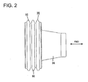
- the back wall 53 is formed with a substantially tubular portion 56 substantially in the form of a truncated cone, as a whole, substantially having a trapezoidal plan view projecting backward from the back wall 53. More specifically, the tubular portion 56 has a tapered shape as a whole, communicates with the inner space of the mounting portion 15 by having the wire insertion hole 55, and is gradually narrowed toward the projecting end PE from the base end where the inner circumferential surface of the wire insertion hole 55 is connected with the back wall 53 of the rear holder 50.
- a rear part of the sealing member 98 is at least partly fittable into the wire insertion hole 55 of the tubular portion 56.
- the sealing member 98 is comprised of a seal main body 96 to be at least partly fitted into the inner space of the mounting portion 15 and held substantially in close contact with the outer circumferential surface of the wire W and the inner circumferential surface of the mounting portion 15, and a shake preventing portion 94 integrally or unitarily continuous with the seal main body 96 to be likewise held substantially in close contact with the outer circumferential surface of the wire W and/or the inner circumferential surface of the wire insertion hole 55 of the tubular portion 56 (rear holder 50).
- the shake preventing portion 94 has a shape substantially corresponding to or matching the shape of the wire insertion hole 55.
- This shake preventing portion 94 and the seal main body 96 are arranged one after the other in forward and backward directions FBD (longitudinal direction).
- the seal main body 96 is formed to have such a thickness as to substantially fill up a space present between the outer circumferential surface of the wire W and the inner circumferential surface of the mounting portion 15, and has one or more, preferably a plurality of lips 93 (substantially extending at least partly in circumferential direction) formed on the inner and/or outer circumferential surfaces thereof.
- the lips 93 are held or holdable in contact with the outer circumferential surface of the wire W and/or the inner circumferential surface of the mounting portion 15 while being compressed in thickness direction or radial direction when the sealing member 98 is mounted into the mounting portion 15.
- the shake preventing portion 94 preferably has no part corresponding to the lips 93 and has substantially flat inner and outer circumferential surfaces.
- the shake preventing portion 94 projects, substantially coaxially with the sealing member 96, backward from an intermediate part (preferably at an angle different from 0° or 180°, preferably substantially from a middle part) of the rear surface of the seal main body 96, and the inner circumferential surface thereof serves as a wire contact surface that extends substantially horizontally without forming any step to the inner circumferential surface of the seal main body 96.
- the shake preventing portion 94 has a conical or trunco-conical shape substantially corresponding to the shape of the tubular portion 56, and the inner surface thereof is shaped substantially in conformity with the outer circumferential surface of the wire W while the outer circumferential surface thereof is tapered or dimensioned substantially in conformity with the inner circumferential surface of the tubular portion 56 (inner circumferential surface of the wire insertion hole 55).
- the inner circumferential surface of the shake preventing portion 94 has an inner diameter slightly smaller than the outer diameter of the wire W and/or the outer circumferential surface thereof has an outer diameter slightly larger than the inner diameter of the tubular portion 56.
- the shake preventing portion 94 is held substantially in close contact with the outer circumferential surface of the wire W and/or the inner circumferential surface of the tubular portion 56 while being squeezed or compressed between the two surfaces.
- FBD forward and backward directions
- an inner fitting portion 58 is so formed on the inner surface (front surface) of the back wall 53 except the outer peripheral edge thereof as to project slightly forward.
- This inner fitting portion 58 has an outer peripheral edge substantially concentric with the back wall 53 and an inner peripheral edge continuous with the tubular portion 56, and the inner or front surface thereof is a substantially flat surface being arranged at an angle different from 0° or 180°, preferably substantially normal to the forward and backward directions FBD or substantially vertical so that it can be held substantially in surface contact with the rear surface of the sealing member 98.
- This inner fitting portion 58 is substantially closely fitted into the mounting portion 15, and the outer circumferential surface thereof can be held substantially in close contact with the inner circumferential surface of the mounting portion 15.
- a fitting space into which a rear-end opening edge of the mounting portion 15 is at least partly fittable is defined between the outer circumferential surface of the inner fitting portion 58 and the inner circumferential surface of the mounting portion 15.
- a bulging portion 61 preferably having a gate-shaped cross section bulging or projecting substantially radially outward is formed at (preferably a bottom end part of) the surrounding wall 54, and the guidable groove 52 is formed substantially in forward and backward directions FBD in this bulging portion 61.
- the bulging portion 61 interferes with the rear-end opening edge of the mounting portion 15 to hinder any further mounting operation.
- the improper posture of the rear holder 50 can be recognized at the start of the mounting operation of the rear holder 50.
- the one or more, preferably the pair of locking pieces 51 resiliently engageable with the respective interlocking portions 34 of the mounting portion 15 are formed at the lateral (left and/or right) side(s) of the surrounding wall 54.
- Each locking piece 51 preferably substantially is in the form of a gate-shaped frame and resiliently deformable substantially inward and outward between a pair of (upper and lower) slits 62 making openings at the front end of the surrounding wall 54 and substantially extending backward, and is formed with a locking groove extending backward to make an opening at the rear end of the locking piece 51 while leaving the front end of the locking piece 51.
- the front ends of the locking pieces 51 move onto the one or more interlocking portions 34 to resiliently deform the locking pieces 51.
- the interlocking portions 34 at least partly enter the locking grooves 63 while the locking pieces 51 are resiliently restored, whereby the rear holder 50 is or can be inseparably locked on the mounting portion 15.
- one or more, preferably a plurality of ribs 64 having wider leading ends (a dove-tail shape) than base ends are provided on the inner circumferential surface of the surrounding wall 64 while preferably being circumferentially spaced apart.
- the ribs 64 have a trapezoidal or undercut cross section gradually widened from the base end toward the leading end, more specifically substantially an isosceles trapezoidal cross section, and a total of four ribs 64 are formed while being substantially equally spaced apart in circumferential direction, more specifically at circumferential intervals of about 90°.
- These ribs 64 are located at positions substantially to correspond to or face the recesses 37 when the rear holder 50 substantially is right opposed to the mounting portion 15 and engageable with the dovetail or undercut recesses 37, whereby the ribs 64 and the recesses 37 are locked into each other in radial directions.
- recessed grooves 65 are formed on the outer circumferential surface of the surrounding wall 54 preferably at positions having a substantially back-to-back relationship (or substantially being radially aligned) with the above ribs 64. These recessed grooves 65 preferably have an arcuate or shallow cross section and extend substantially in forward and backward directions FBD, specifically extend substantially along the entire length of the surrounding wall 54 in forward and backward directions FBD.
- the terminal fitting 30 connected with the end of the wire W is at least partly inserted into the cavity 16 of the female housing 10.
- the terminal fitting 30 at least partly enters the tower portion 13 from the mounting portion 15 and is resiliently locked by the locking portion 17 in the tower portion 13.
- the sealing member 98 mounted on the end of the wire W is at least partly fitted and held in the mounting portion 15, and the rear holder 50 having the wire W inserted through the wire insertion hole 55 is mounted on the outer circumferential surface of the mounting portion 15 from the mounting side MS, preferably substantially from behind.
- the guiding rib 36 of the mounting portion 15 is at least partly inserted into the entrance (opening) of the guidable groove 52 of the rear holder 50, and the one or more ribs 64 of the rear holder 50 are at least partly inserted into the respective entrances (openings) of the one or more recesses 37 of the mounting portion 15.
- the ribs 64 can be precisely positioned with respect to the recesses 37 and engaged therewith by substantially aligning the recessed grooves 65 formed on the outer circumferential surface of the rear holder 50 with the mating recesses 37. If the rear holder 50 is pushed substantially forward along the recesses 37 in this state, the frame portions 35 of the mounting portion 15 at least partly enter the slits 62 of the surrounding wall 54 and the leading ends of the locking pieces 51 move substantially onto the guiding surfaces of the interlocking portions 34 while being held substantially in sliding contact therewith, thereby resiliently deforming the locking pieces 51.
- the inner fitting portion 58 of the back wall 53 is at least partly fitted into the rear-end opening edge of the mounting portion 15 to retain the sealing member 98 held in the mounting portion 15, and the interlocking portions 34 are at least partly fitted into the locking grooves 63 as the locking pieces 51 are resiliently at least partly restored.
- the locking pieces 51 are engaged with the locking surfaces of the interlocking portions 34 in a detaching direction of the rear holder 50, whereby the rear holder 50 can be reliably retained.
- the tower portion 13 is at least partly fitted into the receptacle 91 of the mating male housing 90.
- the lock arm 12 is resiliently engaged with the lock portion 95 to lock the two housings 10, 90 into each other.
- the male tab 92 is inserted to a substantially proper depth in the main portion 31 of the terminal fitting 30 to connect the both terminal fittings 30, 92 and the inner circumferential surface of the receptacle 91 comes substantially into close contact with the outer circumferential surface of the seal ring 97 to provide sealing between the two housings 10, 90.
- the shakes of the wire W and the terminal fitting 30 in the female housing 10 can be substantially suppressed by the close contact of the shake preventing portion 94 of the sealing member 98 mounted on this wire W with the outer circumferential surface of the wire W and the inner circumferential surface of the wire insertion hole 55, wherefore the connected positions of the two terminal fittings 30, 92 can be kept constant to improve connection reliability.
- the clearance present between the wire insertion hole 55 and the wire W preferably is substantially filled up by the sealing member 98, there is an advantage of being able to absorb a deviation of positional precision that can be created between the wire insertion hole 55 and the wire W as compared to the case where the outer circumferential surface of the wire W is directly held in close contact with the inner circumferential surface of the wire insertion hole 55.
- the rear holder 50 is formed with the tubular portion 56 having the wire insertion hole 55 inside and projecting backward and the shake preventing portion 94 is held in close contact with the inner circumferential surface of the wire insertion hole 55 in the tubular portion 56, the wire W is or can be held in contact with the tubular portion preferably over the substantially entire length range of the tubular portion 56, wherefore the shake of the wire W in the female housing 10 can be reliably suppressed.
- the inner circumferential surface of the wire insertion hole 55 in the tubular portion 56 is tapered toward the back and the outer circumferential surface of the shake preventing portion 94 is tapered or converging substantially in conformity with the inner circumferential surface of the wire insertion hole 55, if the wire W drawn out through the wire insertion hole 55 is shaken, a shake supporting part is closely held by the shake preventing portion 94 to suppress the shaking movement. Accordingly, a shaking force of the wire W is more unlikely to be transmitted to the connected portions of the both terminal fittings 30, 92, wherefore connection reliability can be further improved.
- a connector F is provided with a female housing 10 for at least partly accommodating at least one terminal fitting 30 connected with an end of a wire W, at least one sealing member 98 for sealing the inside of the female housing 10 by being mounted on the wire W and at least partly fitted into a mounting portion 15 as an opening portion formed in or on (preferably the rear surface of) the female housing 10, and a (preferably rear) holder 50 formed with a wire insertion hole 55, through which the wire W is inserted, and adapted to press the sealing member 98 to prevent the sealing member 98 from coming out by being mounted on the female housing 10 from the mounting side MS (preferably substantially from behind).
- a seal main body 96 to be held substantially in close contact with the outer circumferential surface of the wire W and the inner circumferential surface of the mounting portion 15 and at least one shake preventing portion 94 to be held substantially in close contact with the outer circumferential surface of the wire W and the inner circumferential surface of the wire insertion hole 55 of the rear holder 50 are arranged one after the other in forward and backward directions.
- a connector F is provided with a female housing 110 for at least partly accommodating at least one female terminal fitting 130 and a rear holder 150 (as a preferred holder) to be mounted on this female housing 110 from a mounting side MS, preferably substantially from behind, wherein the female housing 110 is connectable with a mating male housing 190.
- the connector F is also provided with a detecting member 199 for detecting a connected state of the female and male housings 110, 190, a sealing member 198 for providing fluid- or waterproof sealing between the female housing 110 and the terminal fitting 130, and a seal ring 197 for providing fluid- or waterproof sealing between the female and male housings 110 and 190.
- sides of the female and male housings 110, 190 to be connected are referred to as front sides concerning forward and backward directions FBD and reference is made to FIG. 8 concerning vertical direction.
- the mating male housing 190 is made of a synthetic resin and includes a receptacle 191 (preferably substantially in the form of a round tube) having an open front side as shown in FIG. 21. At least one male tab 192 is mounted through the back wall of the receptacle 191.
- the male tab 192 preferably is a plate made of an electrically conductive material (such as metal), substantially aligns its plate surface along forward and backward directions FBD, and at least partly projects into the receptacle 191.
- one or more, preferably a plurality of ribs 193 (projecting portions) are so formed on the inner circumferential surface of the receptacle 191 as to extend substantially in forward and backward directions FBD.
- the ribs 193 are circumferentially spaced apart.
- ribs 193 are provided while being spaced apart at substantially equal circumferential intervals of about 45°.
- the respective ribs 193 are (preferably substantially identically) shaped with a substantially rectangular cross section, have the substantially same width in forward and backward directions FBD, and can come substantially into contact with rib receiving portions 119 of the female housing 110.
- the respective ribs 193 extend up to the back end of the receptacle 191 from a position slightly behind the front edge of the receptacle 191.
- one or more, preferably a pair of lateral (left and/or right) guide ribs 194 are formed to bulge out sideways (preferably from bottom parts) of the opposite lateral sides of the outer circumferential surface of the receptacle 191 and to extend substantially in forward and backward directions FBD. Both guide ribs 194' can at least partly enter guiding portions 111 of the female housing 110. Further, a lock portion 195 projects at an upper end portion of the outer circumferential surface of the receptacle 191. The lock portion 195 is resiliently engageable with a lock arm 112 of the female housing 110.
- one or more, preferably a pair of lateral (left and/or right) protection walls 196 are so formed at the (preferably substantially opposite) side(s) of the lock portion 195 as to extend substantially in forward and backward directions FBD.
- the (preferably both) protection wall(s) 196 is/are designed to protect the lock portion 195 and are arranged at the (preferably substantially opposite) side(s) of the lock arm 112 when the two housings 110, 190 are connected.
- One or more, preferably a pair of lateral (left and/or right) unlocking portions 189 integral or unitary to the corresponding protection walls 196 project from the front ends of the outer side surfaces of the protection walls 196.
- the unlocking portions 189 interfere with the detecting member 199 assembled into the female housing 110 when the two housings 110, 190 are substantially properly connected, thereby canceling a state of the detecting member 199 locked into the female housing 110.
- the female housing 110 is made e.g. of a synthetic resin and, and is provided at or near its front side with a tower portion 113 to be at least partly fitted into the mating receptacle 191 and a tube portion 114 at least partly surrounding the tower portion 113 and defining a space together with the tower portion 113, into which space the receptacle 191 is at least partly inserted, and at its rear side with a mounting portion 115 which is integrally or unitarily continuous with the tower portion 113 and projects substantially backward and on which the rear holder 150 is mounted from the mounting side MS, preferably substantially from behind.
- the one or more guiding portions 111 into which the one or more respective guide ribs 194 of the receptacle 191 are to be at least partly inserted from front to guide the connecting operation of the two housings 110, 190 are so formed at (preferably the bottom left and/or right parts of) the tube portion 114 as to extend preferably over the substantially entire length in forward and backward directions FBD and bulge out sideways or radially.
- the mounting portion 115 preferably has a tubular shape, more specifically a round tubular shape and is one size larger than the tower portion 113 while being smaller than the tube portion 114.
- a cavity 116 communicating with the inner space of the mounting portion 115 penetrates the tower portion 113 in forward and backward directions FBD.
- At least one terminal fitting 130 is at least partly insertable into the cavity 116 through the inner space of the mounting portion 115 from an insertion side, preferably substantially from behind.
- the terminal fitting 130 is comprised of main portion 131 connectable with the male terminal fitting, preferably of a substantially box-shaped main portion 131 into which the male tab 192 is at least partly insertable, and a wire connection portion (preferably comprising a barrel portion 132) continuous with the rear end of the main portion 131 and to be connected (preferably crimped or bent or folded into connection) with a core of a wire W exposed at an end.
- the main portion 131 is at least partly fitted into the cavity 116 of the tower portion 113 while having loose movements thereof prevented, and the barrel portion 132 is arranged in the inner space of the tube portion 114.
- the sealing member 198 made of resilient material (such as rubber) is to be mounted on the wire W adjacent to or behind the barrel portion 132.
- the sealing member 198 is at least partly inserted into the mounting portion 115 from the mounting side MS; preferably substantially from behind, to be brought substantially into close contact with the inner circumferential surface of the mounting portion 115 and the outer circumferential surface of the wire W to provide sealing between these two surfaces.
- the main portion 131 is formed with a locking hole or recess 133, into which a locking portion 117 provided at the inner wall of the cavity 116 is at least partly fitted to retain the terminal fitting 130 in the cavity 116.
- a tab insertion opening 113A for permitting the insertion of the male tab 192 is formed in the front surface of the tower portion 113 preferably as a slit extending in width direction (or a direction at an angle different from 0° or 180°, preferably substantially normal to the forward and backward directions FBD), and the front surface of the main portion 131 faces this tab insertion opening 113A.
- the seal ring 197 made of resilient material (such as rubber) is mounted on the rear part of the outer circumferential surface of the tower portion 113.
- the seal ring 197 is for coming substantially into close contact with the inner circumferential surface of the receptacle 191 and the outer circumferential surface of the tower portion 113 to provide sealing between these two surfaces when the two housings 110, 190 are substantially properly connected.
- One or more, preferably a plurality of rib receiving potions 119 are so formed on the outer circumferential surface of the tower portion 113 as to extend substantially in forward and backward directions FBD preferably while being circumferentially spaced apart.
- the respective rib receiving portions 119 are arranged to substantially face the ribs 193 provided on the inner circumferential surface of the receptacle 191 so that the projecting end surfaces of these can come substantially into contact when the two housings 110, 190 are connected.
- the rib receiving portions 119 preferably include one or more irregularly-shaped ribs 120 (leading-end widened portions) whose leading ends (projecting ends) are wider than the base ends.
- the irregularly-shaped ribs 120 preferably are substantially symmetrically arranged on the lateral (left and right) surfaces of the tower portion 113 with respect to a central or longitudinal axis. Out of these irregularly shaped ribs 120, those located at the opposite ends of the side surfaces in height direction are dovetail ribs 121 having a substantially dovetail-shaped or undercut cross section and those located in the middles of the side surfaces in height direction are substantially T-shaped ribs 122 having a substantially T-shaped cross section.
- the leading end surfaces (projecting end surfaces) of both the dovetail ribs 121 and the T-shaped ribs 122 preferably have substantially arcuate shapes extending substantially along an imaginary arc concentric with the inner circumferential surface of the tube portion 114, and clearances defined between the dovetail ribs 121 and the T-shaped ribs 122 are mold removal spaces formed upon removing pins during the molding.
- Each T-shaped rib 122 includes a supporting strut 122A bulging out substantially radially outward substantially up to the outer circumferential surface of the tower portion 113 and a receiving base 122B extending in a direction at an angle different from 0° or 180°, preferably substantially normal to an extending direction of the supporting strut 122A, and extends from the front end of the tower portion 113 to an intermediate position substantially in forward and backward directions FBD.
- the rear end of this T-shaped rib 122 is set to be slightly before or adjacent to the front end of the sealing member 198.
- the receiving base 122B can support the mating rib 193 preferably over the substantially entire formation range thereof so as to absorb a displacement of the rib 193 within this formation range.
- each receiving base 122B is gradually widened from the front end toward the rear end to narrow the clearances to the dovetail or undercut ribs 121 toward the back side.
- the rib receiving portions 119 except the irregularly shaped ribs 120 are arranged on the distal or upper and lower surfaces of the tower portion 113 and are bored inside to have a tunnel-shaped cross section. Out of these tunnel-shaped ribs, the inside of the one provided on the lower surface of the tower portion 113 is or forms part of a mold removal space formed as the locking portion 117 is formed. Further, a coupling portion 123 bulging out radially outward so as to be substantially continuous with the rear end of the tube portion 114 is formed at the rear end of the tower portion 113.
- the lock arm 112 extends substantially in forward and backward directions FBD at a lateral (upper) part of the female housing 110.
- the lock arm 112 is pivotally displaceable like a seesaw (resiliently displaceable) inwardly and outwardly or towards and away the housing or substantially upward and downward with a center on a supporting portion 124 provided at a position substantially corresponding to the coupling portion 123.
- a front portion (preferably substantially a front half) of the lock arm 112 is arranged in a hidden manner between the tube portion 114 and the tower portion 113, whereas a rear portion (preferably substantially a rear half) thereof is exposed above the mounting portion 115.
- An operable portion 125 pressed for unlocking is provided at the rear end of the lock arm 112 while being slightly elevated.
- An arm accommodating portion 114A bulging to preferably substantially have a gate-shaped cross section is formed at a lateral or upper part of the tube portion 114, and the lock arm 112 is arranged at least partly inside this arm accommodating portion 114A.
- a rear part of the arm accommodating portion 114A is substantially continuous with the upper surface of the mounting portion 115, and an operation window hole 126 is cut out in the upper wall of the arm accommodating portion 114A.
- the operable portion 125 of the lock arm 112 is operated by the finger or hand of an operator inserted through the operation window hole 126 for unlocking.
- the lock arm 112 is formed with at least one lock groove 127 extending substantially in forward and backward directions FBD and making an opening at the rear end of the lock arm 112.
- the lock portion 195 is at least partly fitted into the lock groove 127 and engaged with the front end of the lock groove 127, whereby the housings 110, 190 are inseparably locked into each other.
- the detecting member 199 is at least partly fitted into the lock Igroove 127 of the lock arm 112 from behind.
- the detecting member 199 is displaceable between a push-in preventing position where the detecting member 199 is partly engaged with the lock groove 127 and a detecting position reached by being pushed forward from the push-in preventing position to be properly engaged with the lock groove 127.
- One or more rail grooves 128 are formed to extend substantially in forward and backward directions FBD in the inner surface(s) of the (preferably substantially opposite) side wall(s) of the arm accommodating portion 114A, and one or mroe stoppers 129 engageable with one or more, preferably a pair of lateral (left and/or right) leg portions 199A provided on the detecting member 199 are formed at intermediate positions of the rail grooves 128 with respect to lengthwise direction.
- the detecting member 199 is held or positioned at the push-in preventing position by the engagement of the stoppers 129 and the leg portions 199A.
- the unlocking portions 189 of the receptacle 191 interfere with the leading ends of the leg portions 199A to lift the leg portions 199A outward or upward, whereby the leg portions 199A and the stoppers 129 are disengaged from each other to permit the detecting member 199 to be pushed towards or in to the detecting position.
- one or more, preferably a pair of lateral (left and/or right) interlocking portion(s) 134 project from the outer circumferential surface of the mounting portion 115 at an intermediate part (preferably at a substantially middle part) of the mounting portion 115 with respect to forward and backward directions FBD.
- the interlocking portions 134 are resiliently engageable with one or more respective locking pieces 151 provided at the rear holder 150, wherein the rear surfaces thereof preferably are slanted or inclined guiding surfaces sloped upward or outward toward the front ends and the front surfaces thereof are substantially vertical locking surfaces.
- One or more frame portions 135 are formed at least partly around the interlocking portions 134 in the outer circumferential surface of the mounting portion 115 as shown in FIG. 10.
- the frame portions 135 are for at least partly surrounding the interlocking portions 134 preferably substantially in U-shape while exposing only rear areas (or parts thereof) of the interlocking portions 134.
- the frame portions 135 are arranged substantially along the side edges of the locking pieces 151 after the rear holder 150 is mounted, thereby being able to prevent the locking pieces 151 from being inadvertently resiliently deformed to unlock the rear holder 150 by getting caught by an external matter.
- At least one guiding rib 136 is formed to extend substantially in forward and backward directions FBD at the lateral or bottom end of the outer circumferential surface of the mounting portion 115, and is engageable with at least one respective guidable groove 152 formed in the rear holder 150.
- one or more, preferably a plurality of recesses 137 are formed in the outer circumferential surface of the mounting portion 115 preferably while being circumferentially spaced apart. These recesses 137 preferably are in the form of dovetail or undercut grooves whose cross sections are gradually widened toward the bottom surfaces (as they get deeper).
- a total of four recesses 137 are formed while being substantially equally spaced apart in circumferential direction, more specifically at circumferential intervals of about 90°.
- the recesses 137 are formed to extend substantially in forward and backward directions FBD, the rear ends thereof are exposed at the rear surface (opening surface) of the mounting portion 115 and the front ends thereof are located at the same position as the rear end of the arm accommodating portion 114A of the tube portion 114 with respect to forward and backward directions FBD.
- one or more, preferably a pair of lateral (left and/or right) ones arranged at an upper part are substantially continuous with the base ends of the opposite side walls of the arm accommodating portion 114A.
- the rear holder 150 is made of a synthetic resin and in the form of a cap, more specifically a bottomed cylinder as shown in FIGS. 14 to 16 so as to be mountable on the mounting portion 115 from behind.
- This rear holder 150 includes a substantially disk-shaped back wall 153 and a substantially cylindrical surrounding wall 154 projecting forward from the peripheral edge of the back wall 153, wherein the surrounding wall 154 is fittable on the mounting portion 115 and the back wall 153 can close the opening of the mounting portion 115 and can retain the sealing member 198.
- a wire insertion hole 155 through which the wire W is at least partly inserted is formed in an intermediate part (preferably substantially in the center) of the back wall 153.
- a (preferably substantially cylindrical) tubular portion 156 is formed to project substantially backward from or at the rear surface of the back wall 153, and a wire insertion path 157 (preferably substantially coaxially) communicating with the wire insertion hole 155 while preferably having the substantially same diameter is formed to extend substantially in forward and backward directions FBD in this tubular portion 156.
- One wire W connected with the terminal fitting 130 is at least partly inserted through and held in the wire insertion hole 155 and the wire insertion path 157 while having loose movements thereof prevented.
- a length of the tubular portion 156 in forward and backward directions FBD is less than the length of the surrounding wall 154, preferably less than about 2/3 of the length of the surrounding wall 154 , most preferably about half the length of the surrounding wall 154 in forward and backward directions FBD.
- an inner fitting portion 158 is so formed on the inner surface (front surface) of the back wall 153 except the outer peripheral edge thereof as to project slightly forward.
- This inner fitting portion 158 has an outer peripheral edge substantially concentric with the back wall 153 and/or an inner peripheral edge defining the wire insertion hole 155, and/or the inner or front surface thereof is a substantially vertical flat surface so that it can be held substantially in surface contact with the rear surface of the sealing member 198.
- This inner fitting portion 158 is closely at least partly fitted into the mounting portion 115, and the outer circumferential surface thereof can be held substantially in close contact with the inner circumferential surface of the mounting portion 115.
- a fitting space into which a rear-end opening edge of the mounting portion 115 is at least partly fittable is defined between the outer circumferential surface of the inner fitting portion 158 and the inner circumferential surface of the mounting portion 115.
- one or more, preferably a plurality of recessed portions 159 are formed in the outer surface (rear surface) of the back wall 153 at one or more positions substantially corresponding to the inner fitting portion 158 so as to prevent an occurrence of a surface sink in the back wall 153.
- a bulging portion 161 preferably substantially having a gate-shaped cross section and bulging radially outward is formed at or near a lateral or bottom end part of the surrounding wall 154, and the guidable groove 152 is formed substantially in forward and backward directions FBD in this bulging portion 161.
- the bulging portion 161 interferes with the rear-end opening edge of the mounting portion 115 to hinder any further mounting operation.
- the improper posture of the rear holder 150 can be recognized at the start of the mounting operation of the rear holder 150.
- the pair of locking pieces 151 resiliently engageable with the interlocking portions 134 of the mounting portion 115 are formed at the lateral (left and/or right) side(s) of the surrounding wall 154.
- Each locking piece 151 preferably is substantially in the form of a gate-shaped frame, is resiliently deformable substantially inward and outward preferably between a pair of upper and lower slits 162 making openings at the front end of the surrounding wall 154 and extending backward, and is formed with a locking groove 163 extending substantially backward to make an opening at the rear end of the locking piece 151 while leaving the front end of the locking piece 151.
- the front ends of the locking pieces 151 move onto the interlocking portions 134 to resiliently deform the locking pieces 151.
- the interlocking portions 134 at least partly enter the locking grooves 163 while the locking pieces 151 are resiliently at least partly restored, whereby the rear holder 150 is inseparably locked on the mounting portion 115.
- leading-end widened ribs 164 having leading ends wider than base ends are provided on the inner circumferential surface of the surrounding wall 154 preferably while being circumferentially spaced apart. More specifically, the leading-end widened ribs 164 have a trapezoidal cross section gradually widened from the base end toward the leading end, more specifically an isosceles trapezoidal cross section, and a total of four leading-end widened ribs 164 are formed while being substantially equally spaced apart in circumferential direction, more specifically at circumferential intervals of about 90°.
- the leading-end widened ribs 164 are formed to preferably extend substantially over the entire length of the surrounding wall 154 in forward and backward directions FBD, so that the front ends thereof are located at or near a front-end opening edge of the rear holder 150 and/or the rear ends thereof are located on or near the front surface of the back wall 153.
- the aforementioned locking pieces 151 are arranged between and substantially equidistant from the leading-end widened ribs 164 adjacent to each other in vertical direction (height direction).
- leading-end widened ribs 164 are located at positions to face the recesses 137 when the rear holder 150 is right opposed to the mounting portion 115 and engageable with the dovetail recesses 137, whereby the leading-end widened ribs 164 and the recesses 137 are locked into each other substantially in radial directions.
- one or more recessed grooves 165 are formed in the outer circumferential surface of the surrounding wall 154 at positions preferably substantially having a back-to-back relationship with the above leading-end widened ribs 164 or substantially radially aligned therewith.
- These recessed grooves 165 have an arcuate or shallow cross section and extend substantially in forward and backward directions FBD, specifically extend over the entire length of the surrounding wall 154 in forward and backward directions FBD.
- the recessed grooves 165 and the leading-end widened ribs 164 preferably are substantially transversely symmetrical as a whole with respect to an axial line along a radial direction.
- the terminal fitting 130 connected with the end of the wire W is at least partly inserted into the cavity 116 of the female housing 110.
- the terminal fitting 130 at least partly enters the tower portion 113 from the mounting portion 115 and is resiliently locked by the locking portion 117 in the tower portion 113.
- the sealing member 198 mounted on the end of the wire W is at least partly fitted and held in the mounting portion 115.
- the seal ring 197 is mounted on or to (preferably the rear end of) the tower portion 113, and the holder or rear holder 150 having the wire W inserted through the wire insertion hole 155 and the wire insertion path 157 is held or positioned preferably on standby at an intermediate position of the wire W along its extending direction.
- the holder or rear holder 150 is mounted on the mounting portion 115 from the mounting side MS, preferably substantially from behind.
- the guiding rib 136 of the mounting portion 115 is at least partly inserted into the entrance (opening) of the guidable groove 152 of the rear holder 150, and the leading-end widened ribs 164 of the rear holder 150 are at least partly inserted into the entrances (openings) of the recesses 137 of the mounting portion 115.
- leading-end widened ribs 164 can be precisely positioned with respect to the recesses 137 and engaged therewith by aligning the recessed grooves 165 formed in the outer circumferential surface of the rear holder 150 with the mating recesses 137. If the rear holder 150 is pushed substantially forward along the recesses 137 in this state, the frame portions 135 of the mounting portion 115 at least partly enter the slits 162 of the surrounding wall 154 from front and the leading ends of the locking pieces 151 move onto the guiding surfaces of the interlocking portions 134 while being held substantially in sliding contact therewith, thereby resiliently deforming the locking pieces 151.
- the inner fitting portion 158 of the back wall 153 is at least partly fitted into the rear-end opening edge of the mounting portion 115 to retain the sealing member 198 held in the mounting portion 115, and the interlocking portions 134 are at least partly fitted into the locking grooves 163 as the locking pieces 151 are resiliently at least partly restored.
- the locking pieces 151 are engaged with the locking surfaces of the interlocking portions 134 substantially in a detaching direction of the rear holder 150, whereby the rear holder 150 can be reliably retained.
- the rear holder 150 When the rear holder 150 is mounted on the mounting portion 115 up to a substantially proper depth in this way, the front ends of the leading-end widened ribs 164 can be held in contact with the front surfaces of the recesses 137 and the locking pieces 151 are surrounded by the frame portions 135 of the mounting portion 115.
- the tower portion 113 is at least partly fitted into the receptacle 191 of the mating male housing 190.
- the lock arm 112 is resiliently engaged with the lock portion 195 to lock the two housings 110, 190 into each other, and the detecting member 199 is unlocked by the unlocking portions 189 and pushed in to the detecting position.
- the detecting member 199 cannot be pushed in, it can be known that the two housings 110, 190 are left partly connected, wherefore the two housings 110, 190 are deeper connected to reach a substantially properly connected state.
- the male tab 192 is at least partly inserted to a proper depth in the main portion 131 of the terminal fitting 130 to connect the both terminal fittings 130, 192 and the inner circumferential surface of the receptacle 191 comes substantially into close contact with the outer circumferential surface of the seal ring 197 to provide sealing between the two housings 110, 190.
- the wire W drawn out from the female housing 110 is shaken in a direction intersecting with the longitudinal direction or the forward and backward directions FBD after the two housings 110, 190 are connected, a pulling force acts on the rear holder 150 in the substantially same direction intersecting with the longitudinal direction. Then, the rear holder 150 is inclined within the range of a clearance to the mounting portion 115 and, in a worst case, the interlocking portions 134 may be separated from the locking grooves 163 to unlock the rear holder 150.
- the rear holder 150 and the mounting portion 115 can be held in close contact by the dovetail engagement of the leading-end widened ribs 164 and the recesses 137 substantially in radial directions.
- the seal ring 197 does not inadvertently come out of the mounting portion 115 since the detachment of the rear holder 150 from the mounting portion 115 is hindered by the dovetail engagement of the leading-end widened ribs 164 and the recesses 137.
- the leading-end widened ribs 164 are formed up to the back wall 153, a shaking force of the wire W is suppressed at a shake supporting part of the wire W, whereby the detachment of the rear holder 150 can be reliably hindered.
- the surrounding wall 154 of the rear holder 150 preferably has a substantially cylindrical or tube-like shape and the leading-end widened ribs 164 are provided on the inner circumferential surface of the surrounding wall 154 and cannot be seen laterally from the outside, the mounting operation of the rear holder 150 is stopped if the rear holder 150 is rotated or pivoted about its central axis from a substantially proper mounting position upon mounting the rear holder 150.
- the one or more recessed grooves 165 are formed at the one or more positions of the outer circumferential surface of the surrounding wall 154 substantially corresponding to the leading-end widened ribs 164, they can function as one or more markers for positioning upon mounting the rear holder 150.
- the rear holder 150 can be mounted in a proper posture on the mounting portion 115 by starting the mounting operation of the rear holder 150 in a state where the recessed grooves 165 and the recesses 137 are aligned along straight lines.
- these recessed grooves 165 are formed preferably at the positions substantially having a back-to-back relationship with the leading-end widened ribs 164, parts of the surrounding wall 154 where the leading-end widened ribs 164 are formed are not excessively thickened, thereby suppressing an occurrence of surface sinks. Furthermore, since the inner fitting portion 158 of the rear holder 150 is at least partly fitted into the mounting portion 115, even if the wire W is largely shaken, the inner fitting portion 158 and the mounting portion 115 are engaged with each other in a shaking direction (direction intersecting with the longitudinal direction) and the inner fitting portion 158 is caught by the mounting portion 115, wherefore the detachment of the rear holder 150 can be more reliably prevented.
- the projecting ends of the ribs 193 and the irregularly shaped ribs 120 can be reliably brought into contact with each other since the one or more irregularly shaped ribs 120 include circumferentially extending parts (e.g. receiving bases 122B) and can support the ribs 193 within their formation ranges. As a result, a shake that can occur between the two housings 110, 120 can be reliably suppressed.
- the irregularly shaped ribs 120 project from the tower portion 113 toward the receptacle 191 and the ribs 193 project from the receptacle 191 toward the tower portion 113.
- the projecting distance of the ribs 193 can be suppressed as compared to the case where the ribs (irregularly shaped ribs) project from only either one of the tower portion 113 and the receptacle 191.
- the strength of the ribs 193 irregularly shaped ribs 120
- the irregularly shaped ribs 120 include the T-shaped ribs 122 each comprised of the supporting strut 122A and the receiving base 122B, an occurrence of sinks in the supporting struts 122A can be prevented even if the formation ranges of the receiving bases 122B are enlarged.
- a connector F is provided with a female housing 110 for at least partly accommodating at least one terminal fitting 130 to be connected with an end of a wire W, and a rear holder 150 (as a preferred holder) substantially having a cap shape by being comprised of a back wall 153 and a surrounding wall 154 projecting forward from the back wall 153 and mountable on a mounting portion 115 of the female housing 110 from a mounting side, preferably substantially from behind, the back wall 153 being formed with at least one wire insertion hole 155 through which the wire W drawn out through the rear surface of the female housing 110 is at least partly inserted.
- One or more leading-end widened ribs 164 extending substantially in forward and backward directions FBD and having leading ends wider than base ends are provided on the inner circumferential surface of surrounding wall 154 while being circumferentially spaced apart.
- One or more recesses 137 having shapes substantially corresponding to those of the leading-end widened ribs 164 for dovetail or undercut engagement are formed in the outer circumferential surface of the mounting portion 115 at positions corresponding to the leading-end widened ribs 164.
Abstract
Description
- The present invention relates to a connector.
- A known connector is provided with a connector housing for accommodating a terminal fitting connected with an end of a wire, a sealing member mounted on the wire and fitted into an opening portion at the rear end of the connector housing, and a rear holder mounted on the connector housing from behind to press and retain the sealing member (see, for example,
Japanese Unexamined Patent Publication No. 2004-171831 - When the above connector is connected with a mating connector to connect the terminal fitting with a mating terminal fitting and the wire drawn out of the connector housing is shaken in this state, the wire arranged in the connector housing shakes within the range of a clearance present between the wire and the wire insertion hole, with the result that both terminal fittings might be brought into sliding contact with each other. Then, there is a possibility that connected positions of both terminal fittings change to impair connection reliability.
- Further, in the connector disclosed in
Japanese Unexamined Patent Publication No. 2004-171831 - If the inner surface of the wire insertion hole of the rear holder is pressed by the wire when the wire is shaken in a direction intersecting with the longitudinal direction thereof, there is a possibility that the interlocking portion and the locking piece are disengaged by the resulting pressing force to detach the rear holder from the mounting portion.
- The present invention was developed in view of the above situation and an object thereof is to improve the overall operability of the connector, particularly by improving the connection reliability of a terminal fitting and/or by preventing a rear holder from being inadvertently detached from a mounting portion.
- This object is solved according to the invention by the features of the independent claims. Preferred embodiment of the invention are subject of the dependent claims.
- According to the invention, there is provided a connector, comprising:
- a connector housing for at least partly accommodating at least one terminal fitting connected with an end of a wire,
- at least one sealing member for sealing the inside of the connector housing by being mounted on the wire and at least partly fitted into an opening portion formed in the rear surface of the connector housing, and
- a rear holder formed with at least one wire insertion hole, through which the wire is inserted, and adapted to press the sealing member to prevent the sealing member from coming out by being mounted on the connector housing from behind a mounting side,
- If the wire drawn out of the connector housing is shaken with the connector housing connected with a mating connector housing, the shake preventing portion of the sealing member mounted on this wire comes substantially into close contact with the outer circumferential surface of the wire and the inner circumferential surface of the wire insertion hole of the holder, thereby suppressing the shake of the wire in the connector housing. Thus, relative sliding movements of the terminal fitting connected with the end of this wire and a mating terminal fitting can be avoided. Accordingly, connected positions of both terminal fittings can be kept substantially constant to improve connection reliability. In this case, a clearance present between the wire insertion hole and the wire is at least partly filled up by the sealing member. Therefore, there is an advantage of being able to absorb a deviation of positional precision that can be created between the wire insertion hole and the wire as compared to the case where the outer circumferential surface of the wire is directly held in close contact with the inner circumferential surface of the wire insertion hole.
- According to a preferred embodiment of the invention, there is provided a connector, comprising:
- a connector housing for accommodating a terminal fitting connected with an end of a wire,
- a sealing member for sealing the inside of the connector housing by being mounted on the wire and fitted into an opening portion formed in the rear surface of the connector housing, and
- a rear holder formed with a wire insertion hole, through which the wire is inserted, and adapted to press the sealing member to prevent the sealing member from coming out by being mounted on the connector housing from behind,
- Preferably, the holder (preferably the rear holder) is formed with a substantially tubular portion having the wire insertion hole inside and projecting substantially backward, and the shake preventing portion is held substantially in close contact with the inner circumferential surface of the wire insertion hole in the tubular portion.
- Since the rear holder is formed with the substantially tubular portion having the wire insertion hole inside and projecting substantially backward and the shake preventing portion is held substantially in close contact with the inner circumferential surface of the wire insertion hole in the tubular portion, the wire is held in contact with the tubular portion over the substantially entire length range of the tubular portion, wherefore the shake of the wire in the connector housing can be reliably suppressed.
- More preferably, the inner circumferential surface of the wire insertion hole in the tubular portion is tapered toward the rear end of the tubular portion, and the outer circumferential surface of the shake preventing portion is tapered substantially in conformity with the inner surface of the wire insertion hole.
- Since the inner circumferential surface of the wire insertion hole in the tubular portion is tapered toward the rear end of the tubular portion and the outer circumferential surface of the shake preventing portion is tapered substantially in conformity with the inner surface of the wire insertion hole, if the wire drawn out of the wire insertion hole of the tubular portion is shaken, a shake supporting portion thereof is closely held by the shake preventing portion to suppress the shaking movement. Therefore, a shaking force of the wire is more unlikely to be transmitted to the connected parts of the both terminal fittings, thereby further improving the connection reliability.
- Further preferably, the seal main body is formed to have such a thickness as to substantially fill up a space present between the outer circumferential surface of the wire and the inner circumferential surface of the mounting portion and/or has one or more lips formed on the inner and/or outer circumferential surfaces thereof.
- Most preferably, the shake preventing portion has substantially flat inner and/or outer circumferential surfaces.
- According to a further aspect of the invention, there is provided a connector, in particular according to the above aspect of the invention or a preferred embodiment thereof, comprising:
- a connector housing for at least partly accommodating at least one terminal fitting to be connected with a wire, and
- a holder substantially having a cap shape by being comprised of a back wall and a surrounding wall projecting substantially forward from the back wall and mountable on a mounting portion of the connector housing from a mounting side, the back wall being formed with at least one wire insertion hole through which the wire can be drawn out through the respective surface of the connector housing,
- If the wire drawn out through the wire insertion hole of the holder from the respective surface of the connector housing is shaken in a direction intersecting or at an angle different from 0° or 180 with respect to forward and backward directions, there is a possibility that a pressing force acts on the holder in a shaking direction of the wire and the holder may be detached from the connector housing. However, according to the above, the at least one leading-end widened rib having the leading end wider than the base end or substantially having a dovetail-shape or being undercut is provided on either one of the inner circumferential surface of the surrounding wall of the rear holder and the outer circumferential surface of the mounting portion, the recess is formed in the other surface, and these leading-end widened rib and recess provide the dovetail engagement or a positive joint or a form closure when the holder is mounted. This can prevent the holder from being detached from the connector housing even if the wire is shaken or the entire connector receives certain vibration.
- According to a preferred embodiment of the invention, there is provided a connector, comprising:
- a connector housing for accommodating a terminal fitting connected with an end of a wire, and
- a rear holder having a cap shape by being comprised of a back wall and a surrounding wall projecting forward from the back wall and mountable on a mounting portion of the connector housing from behind, the back wall being formed with a wire insertion hole through which the wire drawn out through the rear surface of the connector housing is inserted,
- If the wire drawn out through the wire insertion hole of the rear holder from the rear surface of the connector housing is shaken in a direction intersecting with forward and backward directions, there is a possibility that a pressing force acts on the rear holder in a shaking direction of the wire and the rear holder is detached from the connector housing. However, according to the above, the leading-end widened rib having the leading end wider than the base end is provided on either one of the inner circumferential surface of the surrounding wall of the rear holder and the outer circumferential surface of the mounting portion, the recess is formed in the other surface, and these leading-end widened rib and recess provide the dovetail engagement when the rear holder is mounted. This can prevent the rear holder from being detached from the connector housing even if the wire is shaken or the entire connector receives certain vibration.
- Preferably, out of the leading-end widened rib and the recess, the one provided at the inner circumferential surface of the surrounding wall of the holder (preferably the rear holder) extends substantially up to the back wall of the holder (preferably the rear holder).
- Since, out of the leading-end widened rib and the recess, the one provided at the inner circumferential surface of the surrounding wall of the (rear) holder extends up to the back wall of the (rear) holder, the detachment of the (rear) holder from the connector housing can be reliably prevented.
- Further preferably, the surrounding wall of the holder (preferably the rear holder) has a substantially cylindrical shape,
the leading-end widened rib is provided on the inner circumferential surface of the surrounding wall, and
at least one recessed groove is formed in the outer circumferential surface of the surrounding wall at a position substantially having a back-to-back relationship (or being substantially radially aligned) with the leading-end widened rib. - If the (rear) holder is not distinguishable in circumferential direction when the surrounding wall of the (rear) holder has a cylindrical shape, there is a possibility that it becomes difficult to align the leading-end widened rib provided on the inner circumferential surface of the surrounding wall and the recess to a targeted position, making it difficult to mount the (rear) holder on the mounting portion. However, according to the above, the recessed groove is formed in the outer circumferential surface of the surrounding wall at the position having the back-to-back relationship with the leading-end widened rib formed on the inner circumferential surface of the surrounding wall. Thus, the leading-end widened rib can be engaged with the recess using the recessed groove as a marker by positioning this recessed groove and the recess formed in the outer circumferential surface of the mounting portion relative to each other. As a result, the (rear) holder can be precisely mounted on the mounting portion with good operability. Further, by forming the recessed groove at the position substantially corresponding to the leading-end widened rib, an increase in the thickness of the surrounding wall can be suppressed to prevent an occurrence of a surface sink even if the leading-end widened rib is provided. Furthermore, by providing the leading-end widened rib on the inner circumferential surface of the surrounding wall, an undesirable situation where the leading-end widened rib is broken by getting caught by an external matter can be avoided.
- Most preferably, the mounting portion has a substantially tubular shape having an open rear surface, and/or
the back wall of the holder (preferably the rear holder) includes an inner fitting portion to be at least partly fitted into the mounting portion while holding the mounting portion in thickness direction together with the surrounding wall. - When the inner fitting portion of the (rear) holder is fitted into the mounting portion of the connector housing, the mounting portion is held between the inner fitting portion and the surrounding wall in thickness direction and the outer circumferential surface of the inner fitting portion is held substantially in close contact with the inner circumferential surface of the mounting portion. Thus, even if the wire is largely shaken, the inner fitting portion is kept closely fitted in the mounting portion, whereby the detachment of the (rear) holder from the connector housing can be more reliably prevented.
- These and other objects, features and advantages of the present invention will become more apparent upon reading of the following detailed description of preferred embodiments and accompanying drawings. It should be understood that even though embodiments are separately described, single features thereof may be combined to additional embodiments.
- FIG. 1 is a side view in section of a connector according to one embodiment connected with a mating connector,
- FIG. 2 is a side view of the connector connected with the mating connector,
- FIG. 3 is a side view of a female housing,
- FIG. 4 is a side view in section of a rear holder,
- FIG. 5 is a front view of the rear holder,
- FIG. 6 is a side view in section of a sealing member, and
- FIG. 7 is a side view of the sealing member.
- FIG. 8 is a side view of a connector according to one embodiment,
- FIG. 9 is a side view in section of the connector in a connected state,
- FIG. 10 is a side view of a female housing,
- FIG. 11 is a rear view of the female housing,
- FIG. 12 is a plan view of the female housing,
- FIG. 13 is a vertical section of an essential portion of the connector showing a state where a rear holder is mounted on a mounting portion,
- FIG. 14 is a side view of the rear holder,
- FIG. 15 is a front view of the rear holder,
- FIG. 16 is a rear view of the rear holder,
- FIG. 17 is a side view partly in section showing an essential portion of the female housing,
- FIG. 18 is a horizontal section of the female housing,
- FIG. 19 is a horizontal section of the connector showing a state where a tower portion is fitted in a receptacle,
- FIG. 20 is a vertical section of an essential portion of the connector showing the state where the toper portion is fitted in the receptacle, and
- FIG. 21 is a side view in section of a male housing.
- A first preferred embodiment of the present invention is described with reference to the FIGS. 1 to 7. A connector F is provided with a female housing 10 (corresponding to a preferred connector housing) for at least partly accommodating a female terminal fitting 30 and a rear holder 50 (as a preferred holder) to be mounted on this
female housing 10 from a mounting side MS, preferably substantially from behind or from a side substantially opposite to a mating side with a mating connector, wherein thefemale housing 10 is connectable with a matingmale housing 90. The connector F is further provided with a sealingmember 98 for providing fluid- or waterproof sealing between thefemale housing 10 and the terminal fitting 30, and aseal ring 97 for providing fluid- or waterproof sealing between the female andmale housings male housings - The mating
male housing 90 is made e.g. of a synthetic resin and includes areceptacle 91 preferably substantially in the form of a round tube having an open front side. One male tab 92 (male terminal fitting) is mounted through the back wall of thereceptacle 91. Themale tab 92 preferably is substantially a plate made of an electrically conductive material such as a metal, substantially aligns its plate surface along forward and backward directions FBD, and at least partly projects into thereceptacle 91. Alock portion 95 projects at a lateral part (preferably an upper end part) of the outer circumferential surface of thereceptacle 91. Thelock portion 95 is resiliently engageable with alock arm 12 of thefemale housing 10. - Next, the
female housing 10 is described. Thefemale housing 10 is made e.g. of a synthetic resin and, and is provided at or near its front side with atower portion 13 to be at least partly fitted into themating receptacle 91 and afitting tube portion 14 at least partly surrounding thetower portion 13 and defining a space together with thetower portion 13, into which space thereceptacle 91 is at least partly inserted or insertable, and at its rear side with a mounting portion 15 (corresponding to a preferred opening portion) which is integrally or unitarily continuous with thetower portion 13 and projects substantially backward and on or to which therear holder 50 is mounted from the mounting side MS, preferably substantially from behind. - The mounting
portion 15 preferably substantially has a tubular shape, more specifically a round tubular shape and is one size larger than thetower portion 13 while being smaller than thefitting tube portion 14. Acavity 16 communicating with the inner space of the mountingportion 15 penetrates or recesses thetower portion 13 substantially in forward and backward directions FBD. One terminal fitting 30 is at least partly insertable into thecavity 16 through the inner space of the mountingportion 15 from an insertion side, preferably substantially from behind. - The
terminal fitting 30 is comprised of a (preferably substantially box-shaped)main portion 31 with which the male terminal fitting is connectable, preferably into which themale tab 92 is at least partly insertable, and a wire connection portion (preferably comprising a barrel portion 32) continuous with the rear end of themain portion 31 and to be connected (preferably crimped or bent or folded into connection) with a core of a wire W exposed at an end. Themain portion 31 is to be at least partly fitted into thecavity 16 of thetower portion 13 preferably while having loose movements thereof substantially prevented, and the barrel portion 32 is arranged in the inner space of thefitting tube portion 14. Themain portion 31 is formed with a locking hole orrecess 33, into which a lockingportion 17 provided at the inner wall of thecavity 16 is at least partly fitted to retain the terminal fitting 30 in thecavity 16. - The sealing
member 98 made of resilient material (such as rubber) is to be mounted on the wire W substantially adjacent to or behind the barrel portion 32. The sealingmember 98 is at least partly inserted into the mountingportion 15 from the mounting side MS, preferably substantially from behind, to be brought substantially into close contact with the inner circumferential surface of the mountingportion 15 and/or the outer circumferential surface of the wire W to provide sealing between these two surfaces. The sealingmember 98 is also at least partly fitted into thewire insertion hole 55 formed in therear holder 50, but this is described in detail later. - A tab insertion opening 13A for permitting the insertion of the
male tab 92 is formed in the front surface of thetower portion 13 as a slit substantially extending in a direction at an angle different from 0° or 180°, preferably substantially normal to the forward and backward directions FBD or in width direction, and the front surface of themain portion 31 substantially faces the rear surface of this tab insertion opening 13A. At the rear end of thetower portion 13, acoupling portion 23 is formed to substantially bulge out or project radially outward so as to be substantially continuous with (preferably the rear end of) thefitting tube portion 14. Theseal ring 97 made of resilient material (such as rubber) is mounted or mountable on the outer circumferential surface of a rear part of thetower portion 13 before thecoupling portion 23. Theseal ring 97 is for coming substantially into close contact with the inner circumferential surface of thereceptacle 91 and/or the outer circumferential surface of thetower portion 13 to provide sealing between these two surfaces when the twohousings fitting tube portion 14, one or more window holes 18 are formed at positions substantially corresponding to theseal ring 97, so that the leading end of thereceptacle 91 can be seen through these window holes 18 when the twohousings - As shown in FIG. 1, the
lock arm 12 extends substantially in forward and backward directions FBD at a lateral part (preferably substantially an upper part) of thefemale housing 10. Thelock arm 12 is pivotally displaceable like a seesaw (resiliently displaceable) substantially inwardly or outwardly (upward and downward) with a center on a supporting portion 24 provided at a position substantially corresponding to thecoupling portion 23. A front portion (preferably a front half) of thelock arm 12 is arranged (preferably in a hidden manner) between thefitting tube portion 14 and thetower portion 13, whereas a rear portion (preferably substantially a rear half) thereof is exposed above or outside of the mountingportion 15. Anoperable portion 25 pressed for unlocking is provided at or near the rear end of thelock arm 12 preferably while being slightly elevated. An armaccommodating portion 14A bulging preferably to have a substantially gate-shaped cross section is formed at a lateral part (preferably an upper part) of thefitting tube portion 14, and thelock arm 12 is arranged inside this armaccommodating portion 14A. Anoperation window hole 26 used to operate thelock arm 12 is cut out at or near the rear end of the upper wall of the armaccommodating portion 14A. Theoperable portion 25 of thelock arm 12 is or can be operated particularly by the finger or hand of an operator at least partly inserted through theoperation window hole 26 for unlocking. - The
lock arm 12 is formed with at least onelock groove 27 extending substantially in forward and backward directions FBD and making an opening at the rear end of thelock arm 12. When the twohousings lock portion 95 is at least partly fitted into thelock groove 27 and engaged with the front end of thelock groove 27, whereby thehousings - On the other hand, as shown in FIG. 3, one or more, preferably a pair of lateral (left and/or right) interlocking portions 34 project from the outer circumferential surface of the mounting
portion 15 at an intermediate part (preferably at a substantially middle part) of the mountingportion 15 with respect to forward and backward directions FBD. The interlocking portions 34 are resiliently engageable with one or morerespective locking pieces 51 provided at therear holder 50, wherein the mating surfaces (rear surfaces) thereof are slanted guiding surfaces sloped substantially outward or upward toward the front ends and the front surfaces thereof are substantially vertical locking surfaces. - One or
more frame portions 35 are formed at least partly around the interlocking portions 34 in the outer circumferential surface of the mountingportion 15. Theframe portions 35 are for at least partly surrounding the interlocking portions 34 preferably substantially in U-shape while exposing only rear areas of the interlocking portions 34. Theframe portions 35 are arranged substantially along the side edges of the lockingpieces 51 after therear holder 50 is mounted, thereby being able to prevent the lockingpieces 51 from being inadvertently resiliently deformed to unlock therear holder 50 by getting caught by an external matter. - At least one guiding
rib 36 is formed to extend substantially in forward and backward directions FBD at (preferably substantially the bottom or outer end of) the outer circumferential surface of the mountingportion 15, and is engageable with at least oneguidable groove 52 formed in or at therear holder 50. One or more, preferably a plurality ofrecesses 37 are formed in the outer circumferential surface of the mountingportion 15 preferably while being circumferentially spaced apart. These one ormore recesses 37 preferably are in the form of dovetail or undercut grooves whose cross sections are gradually widened toward the bottom surfaces (as they get deeper). Particularly, a total of fourrecesses 37 are formed while being substantially equally spaced apart in circumferential direction, more specifically at circumferential intervals of about 90°. - Next, the
rear holder 50 is described. Therear holder 50 is made e.g. of a synthetic resin and preferably substantially in the form of a cap, more specifically a bottomed cylinder as shown in FIGS. 4 and 5 so as to be mountable on the mountingportion 15 from the mounting side MS, preferably substantially from behind. Thisrear holder 50 includes a (preferably substantially disk-shaped)back wall 53 and a (preferably substantially cylindrical) surroundingwall 54 projecting forward from the peripheral edge of theback wall 53, wherein the surroundingwall 54 is at least partly fittable on the mountingportion 15 and theback wall 53 can substantially close the opening of the mountingportion 15 and can retain the sealingmember 98. - A
wire insertion hole 55 through which the wire W is at least partly inserted is formed in an intermediate position (preferably substantially in the center) of theback wall 53. Theback wall 53 is formed with a substantiallytubular portion 56 substantially in the form of a truncated cone, as a whole, substantially having a trapezoidal plan view projecting backward from theback wall 53. More specifically, thetubular portion 56 has a tapered shape as a whole, communicates with the inner space of the mountingportion 15 by having thewire insertion hole 55, and is gradually narrowed toward the projecting end PE from the base end where the inner circumferential surface of thewire insertion hole 55 is connected with theback wall 53 of therear holder 50. A rear part of the sealingmember 98 is at least partly fittable into thewire insertion hole 55 of thetubular portion 56. - Here, as shown in FIGS. 6 and 7, the sealing
member 98 is comprised of a sealmain body 96 to be at least partly fitted into the inner space of the mountingportion 15 and held substantially in close contact with the outer circumferential surface of the wire W and the inner circumferential surface of the mountingportion 15, and ashake preventing portion 94 integrally or unitarily continuous with the sealmain body 96 to be likewise held substantially in close contact with the outer circumferential surface of the wire W and/or the inner circumferential surface of thewire insertion hole 55 of the tubular portion 56 (rear holder 50). In other words, theshake preventing portion 94 has a shape substantially corresponding to or matching the shape of thewire insertion hole 55. Thisshake preventing portion 94 and the sealmain body 96 are arranged one after the other in forward and backward directions FBD (longitudinal direction). The sealmain body 96 is formed to have such a thickness as to substantially fill up a space present between the outer circumferential surface of the wire W and the inner circumferential surface of the mountingportion 15, and has one or more, preferably a plurality of lips 93 (substantially extending at least partly in circumferential direction) formed on the inner and/or outer circumferential surfaces thereof. Thelips 93 are held or holdable in contact with the outer circumferential surface of the wire W and/or the inner circumferential surface of the mountingportion 15 while being compressed in thickness direction or radial direction when the sealingmember 98 is mounted into the mountingportion 15. - The
shake preventing portion 94 preferably has no part corresponding to thelips 93 and has substantially flat inner and outer circumferential surfaces. Theshake preventing portion 94 projects, substantially coaxially with the sealingmember 96, backward from an intermediate part (preferably at an angle different from 0° or 180°, preferably substantially from a middle part) of the rear surface of the sealmain body 96, and the inner circumferential surface thereof serves as a wire contact surface that extends substantially horizontally without forming any step to the inner circumferential surface of the sealmain body 96. Theshake preventing portion 94 has a conical or trunco-conical shape substantially corresponding to the shape of thetubular portion 56, and the inner surface thereof is shaped substantially in conformity with the outer circumferential surface of the wire W while the outer circumferential surface thereof is tapered or dimensioned substantially in conformity with the inner circumferential surface of the tubular portion 56 (inner circumferential surface of the wire insertion hole 55). In a natural state, the inner circumferential surface of theshake preventing portion 94 has an inner diameter slightly smaller than the outer diameter of the wire W and/or the outer circumferential surface thereof has an outer diameter slightly larger than the inner diameter of thetubular portion 56. Accordingly, when the sealingmember 98 is at least partly mounted into the mountingportion 15, theshake preventing portion 94 is held substantially in close contact with the outer circumferential surface of the wire W and/or the inner circumferential surface of thetubular portion 56 while being squeezed or compressed between the two surfaces. By such ashape preventing portion 94, the wire W in thetubular portion 56 can be kept to extend substantially in forward and backward directions FBD (longitudinal direction) substantially without undergoing a buckling deformation. - Further, an inner
fitting portion 58 is so formed on the inner surface (front surface) of theback wall 53 except the outer peripheral edge thereof as to project slightly forward. This innerfitting portion 58 has an outer peripheral edge substantially concentric with theback wall 53 and an inner peripheral edge continuous with thetubular portion 56, and the inner or front surface thereof is a substantially flat surface being arranged at an angle different from 0° or 180°, preferably substantially normal to the forward and backward directions FBD or substantially vertical so that it can be held substantially in surface contact with the rear surface of the sealingmember 98. This innerfitting portion 58 is substantially closely fitted into the mountingportion 15, and the outer circumferential surface thereof can be held substantially in close contact with the inner circumferential surface of the mountingportion 15. A fitting space into which a rear-end opening edge of the mountingportion 15 is at least partly fittable is defined between the outer circumferential surface of the innerfitting portion 58 and the inner circumferential surface of the mountingportion 15. - A bulging
portion 61 preferably having a gate-shaped cross section bulging or projecting substantially radially outward is formed at (preferably a bottom end part of) the surroundingwall 54, and theguidable groove 52 is formed substantially in forward and backward directions FBD in this bulgingportion 61. Upon at least partly mounting therear holder 50 into the mountingportion 15, the rotation of therear holder 50 about its central or longitudinal axis CA can be prevented and the mounting operation of therear holder 50 can be guided by the engagement of theguidable groove 52 of the bulgingportion 61 with the guidingrib 36. If an attempt is made to mount therear holder 50 in an improper posture on the mountingportion 15, the bulgingportion 61 interferes with the rear-end opening edge of the mountingportion 15 to hinder any further mounting operation. Thus, the improper posture of therear holder 50 can be recognized at the start of the mounting operation of therear holder 50. - The one or more, preferably the pair of locking
pieces 51 resiliently engageable with the respective interlocking portions 34 of the mountingportion 15 are formed at the lateral (left and/or right) side(s) of the surroundingwall 54. Each lockingpiece 51 preferably substantially is in the form of a gate-shaped frame and resiliently deformable substantially inward and outward between a pair of (upper and lower) slits 62 making openings at the front end of the surroundingwall 54 and substantially extending backward, and is formed with a locking groove extending backward to make an opening at the rear end of the lockingpiece 51 while leaving the front end of the lockingpiece 51. In the process of mounting therear holder 50 on the mountingportion 15, the front ends of the lockingpieces 51 move onto the one or more interlocking portions 34 to resiliently deform the lockingpieces 51. When therear holder 50 is properly mounted, the interlocking portions 34 at least partly enter the locking grooves 63 while the lockingpieces 51 are resiliently restored, whereby therear holder 50 is or can be inseparably locked on the mountingportion 15. - As shown in FIG: 5 one or more, preferably a plurality of
ribs 64 having wider leading ends (a dove-tail shape) than base ends are provided on the inner circumferential surface of the surroundingwall 64 while preferably being circumferentially spaced apart. More specifically, theribs 64 have a trapezoidal or undercut cross section gradually widened from the base end toward the leading end, more specifically substantially an isosceles trapezoidal cross section, and a total of fourribs 64 are formed while being substantially equally spaced apart in circumferential direction, more specifically at circumferential intervals of about 90°. Theseribs 64 are located at positions substantially to correspond to or face therecesses 37 when therear holder 50 substantially is right opposed to the mountingportion 15 and engageable with the dovetail or undercutrecesses 37, whereby theribs 64 and therecesses 37 are locked into each other in radial directions. - Further, recessed
grooves 65 are formed on the outer circumferential surface of the surroundingwall 54 preferably at positions having a substantially back-to-back relationship (or substantially being radially aligned) with theabove ribs 64. These recessedgrooves 65 preferably have an arcuate or shallow cross section and extend substantially in forward and backward directions FBD, specifically extend substantially along the entire length of the surroundingwall 54 in forward and backward directions FBD. - Next, the procedure of assembling this embodiment is described. First, the terminal fitting 30 connected with the end of the wire W is at least partly inserted into the
cavity 16 of thefemale housing 10. The terminal fitting 30 at least partly enters thetower portion 13 from the mountingportion 15 and is resiliently locked by the lockingportion 17 in thetower portion 13. - Then, the sealing
member 98 mounted on the end of the wire W is at least partly fitted and held in the mountingportion 15, and therear holder 50 having the wire W inserted through thewire insertion hole 55 is mounted on the outer circumferential surface of the mountingportion 15 from the mounting side MS, preferably substantially from behind. At this time, the guidingrib 36 of the mountingportion 15 is at least partly inserted into the entrance (opening) of theguidable groove 52 of therear holder 50, and the one ormore ribs 64 of therear holder 50 are at least partly inserted into the respective entrances (openings) of the one ormore recesses 37 of the mountingportion 15. In this case, theribs 64 can be precisely positioned with respect to therecesses 37 and engaged therewith by substantially aligning the recessedgrooves 65 formed on the outer circumferential surface of therear holder 50 with the mating recesses 37. If therear holder 50 is pushed substantially forward along therecesses 37 in this state, theframe portions 35 of the mountingportion 15 at least partly enter theslits 62 of the surroundingwall 54 and the leading ends of the lockingpieces 51 move substantially onto the guiding surfaces of the interlocking portions 34 while being held substantially in sliding contact therewith, thereby resiliently deforming the lockingpieces 51. When therear holder 50 is mounted on the mountingportion 15 up to a substantially proper depth, the innerfitting portion 58 of theback wall 53 is at least partly fitted into the rear-end opening edge of the mountingportion 15 to retain the sealingmember 98 held in the mountingportion 15, and the interlocking portions 34 are at least partly fitted into the locking grooves 63 as the lockingpieces 51 are resiliently at least partly restored. The lockingpieces 51 are engaged with the locking surfaces of the interlocking portions 34 in a detaching direction of therear holder 50, whereby therear holder 50 can be reliably retained. When therear holder 50 is substantially properly mounted on the mountingportion 15 in this way, it is held substantially in close contact with the outer circumferential surface of the sealingmember 98 from the inner surface of theback wall 53 to the inner surface of thetubular portion 56. - Next, the
tower portion 13 is at least partly fitted into thereceptacle 91 of the matingmale housing 90. When the female andmale housing lock arm 12 is resiliently engaged with thelock portion 95 to lock the twohousings housings male tab 92 is inserted to a substantially proper depth in themain portion 31 of the terminal fitting 30 to connect the bothterminal fittings receptacle 91 comes substantially into close contact with the outer circumferential surface of theseal ring 97 to provide sealing between the twohousings - Even if the wire W drawn out from the
female housing 10 is shaken in a direction intersecting with the longitudinal direction or forward and backward directions FBD after the twohousings portion 15 and the terminal fitting 30 connected with the end of this wire W is not shaken since the wire W is so held as not to make loose movements by theshake preventing portion 94 of the sealingmember 98 at a position corresponding to thetubular portion 56 of therear holder 50. - As described above, according to this embodiment, even if the wire W drawn out from the
female housing 10 is shaken when the female andmale housings female housing 10 can be substantially suppressed by the close contact of theshake preventing portion 94 of the sealingmember 98 mounted on this wire W with the outer circumferential surface of the wire W and the inner circumferential surface of thewire insertion hole 55, wherefore the connected positions of the twoterminal fittings wire insertion hole 55 and the wire W preferably is substantially filled up by the sealingmember 98, there is an advantage of being able to absorb a deviation of positional precision that can be created between thewire insertion hole 55 and the wire W as compared to the case where the outer circumferential surface of the wire W is directly held in close contact with the inner circumferential surface of thewire insertion hole 55. In other words, in the case where the outer circumferential surface of the wire W is directly held in close contact with the inner circumferential surface of thewire insertion hole 55, the inner circumferential surface of thewire insertion hole 55 and the outer circumferential surface of the wire W cannot be kept in close contact if the diameter of thewire insertion hole 55 and the outer diameter of the wire W deviate from specified values due to dimensional errors. However, according to this embodiment, even if the diameter of thewire insertion hole 55 and/or the outer diameter of the wire W deviate from specified (predetermined or predeterminable) values due to dimensional errors, such errors can be absorbed by interposing the resiliently compressible sealingmember 98 between thewire insertion hole 55 and the wire W, wherefore the inner circumferential surface of thewire insertion hole 55 and the outer circumferential surface of the wire W can be kept in close contact. - Further, since the
rear holder 50 is formed with thetubular portion 56 having thewire insertion hole 55 inside and projecting backward and theshake preventing portion 94 is held in close contact with the inner circumferential surface of thewire insertion hole 55 in thetubular portion 56, the wire W is or can be held in contact with the tubular portion preferably over the substantially entire length range of thetubular portion 56, wherefore the shake of the wire W in thefemale housing 10 can be reliably suppressed. - Furthermore, since the inner circumferential surface of the
wire insertion hole 55 in thetubular portion 56 is tapered toward the back and the outer circumferential surface of theshake preventing portion 94 is tapered or converging substantially in conformity with the inner circumferential surface of thewire insertion hole 55, if the wire W drawn out through thewire insertion hole 55 is shaken, a shake supporting part is closely held by theshake preventing portion 94 to suppress the shaking movement. Accordingly, a shaking force of the wire W is more unlikely to be transmitted to the connected portions of the bothterminal fittings - Accordingly, to improve the connection reliability of a terminal fitting, a connector F is provided with a
female housing 10 for at least partly accommodating at least one terminal fitting 30 connected with an end of a wire W, at least one sealingmember 98 for sealing the inside of thefemale housing 10 by being mounted on the wire W and at least partly fitted into a mountingportion 15 as an opening portion formed in or on (preferably the rear surface of) thefemale housing 10, and a (preferably rear)holder 50 formed with awire insertion hole 55, through which the wire W is inserted, and adapted to press the sealingmember 98 to prevent the sealingmember 98 from coming out by being mounted on thefemale housing 10 from the mounting side MS (preferably substantially from behind). In the sealingmember 98, a sealmain body 96 to be held substantially in close contact with the outer circumferential surface of the wire W and the inner circumferential surface of the mountingportion 15 and at least oneshake preventing portion 94 to be held substantially in close contact with the outer circumferential surface of the wire W and the inner circumferential surface of thewire insertion hole 55 of therear holder 50 are arranged one after the other in forward and backward directions. - The present invention is not limited to the above described and illustrated embodiment. For example, the following embodiments are also embraced by the technical scope of the present invention as defined by the claims. Beside the following embodiments, various changes can be made without departing from the scope and spirit of the present invention as defined by the claims.
- (1) Although the rear holder is provided with the tubular portion in the foregoing embodiment, it may not be provided with the tubular portion according to the present invention. In this case, the seal main body of the sealing member may be held substantially in close contact with the inner circumferential surface of the wire insertion hole in the back wall of the rear holder.
- (2) Although the sealing member is made of rubber in this embodiment, it may be made of gel or any other resilient material according to the present invention.
- (3) The present invention is also applicable to the case where a sealing member is at least partly fitted into a rear part of a male housing for accommodating a male terminal fitting and a rear holder is mounted thereon.
- A second preferred embodiment of the present invention is described with reference to FIGS. 8 to 21. A connector F is provided with a
female housing 110 for at least partly accommodating at least one female terminal fitting 130 and a rear holder 150 (as a preferred holder) to be mounted on thisfemale housing 110 from a mounting side MS, preferably substantially from behind, wherein thefemale housing 110 is connectable with a matingmale housing 190. The connector F is also provided with a detectingmember 199 for detecting a connected state of the female andmale housings female housing 110 and theterminal fitting 130, and aseal ring 197 for providing fluid- or waterproof sealing between the female andmale housings male housings - The mating
male housing 190 is made of a synthetic resin and includes a receptacle 191 (preferably substantially in the form of a round tube) having an open front side as shown in FIG. 21. At least onemale tab 192 is mounted through the back wall of thereceptacle 191. Themale tab 192 preferably is a plate made of an electrically conductive material (such as metal), substantially aligns its plate surface along forward and backward directions FBD, and at least partly projects into thereceptacle 191. one or more, preferably a plurality of ribs 193 (projecting portions) are so formed on the inner circumferential surface of thereceptacle 191 as to extend substantially in forward and backward directions FBD. Theribs 193 are circumferentially spaced apart. In a shown case, particularly eightribs 193 are provided while being spaced apart at substantially equal circumferential intervals of about 45°. Therespective ribs 193 are (preferably substantially identically) shaped with a substantially rectangular cross section, have the substantially same width in forward and backward directions FBD, and can come substantially into contact withrib receiving portions 119 of thefemale housing 110. Therespective ribs 193 extend up to the back end of thereceptacle 191 from a position slightly behind the front edge of thereceptacle 191. - As shown in FIG. 20, one or more, preferably a pair of lateral (left and/or right) guide
ribs 194 are formed to bulge out sideways (preferably from bottom parts) of the opposite lateral sides of the outer circumferential surface of thereceptacle 191 and to extend substantially in forward and backward directions FBD. Both guide ribs 194' can at least partly enter guidingportions 111 of thefemale housing 110. Further, alock portion 195 projects at an upper end portion of the outer circumferential surface of thereceptacle 191. Thelock portion 195 is resiliently engageable with alock arm 112 of thefemale housing 110. On the outer circumferential surface of thereceptacle 191, one or more, preferably a pair of lateral (left and/or right)protection walls 196 are so formed at the (preferably substantially opposite) side(s) of thelock portion 195 as to extend substantially in forward and backward directions FBD. The (preferably both) protection wall(s) 196 is/are designed to protect thelock portion 195 and are arranged at the (preferably substantially opposite) side(s) of thelock arm 112 when the twohousings portions 189 integral or unitary to thecorresponding protection walls 196 project from the front ends of the outer side surfaces of theprotection walls 196. The unlockingportions 189 interfere with the detectingmember 199 assembled into thefemale housing 110 when the twohousings member 199 locked into thefemale housing 110. - Next, the
female housing 110 is described. Thefemale housing 110 is made e.g. of a synthetic resin and, and is provided at or near its front side with atower portion 113 to be at least partly fitted into themating receptacle 191 and atube portion 114 at least partly surrounding thetower portion 113 and defining a space together with thetower portion 113, into which space thereceptacle 191 is at least partly inserted, and at its rear side with a mountingportion 115 which is integrally or unitarily continuous with thetower portion 113 and projects substantially backward and on which therear holder 150 is mounted from the mounting side MS, preferably substantially from behind. The one ormore guiding portions 111 into which the one or morerespective guide ribs 194 of thereceptacle 191 are to be at least partly inserted from front to guide the connecting operation of the twohousings tube portion 114 as to extend preferably over the substantially entire length in forward and backward directions FBD and bulge out sideways or radially. The mountingportion 115 preferably has a tubular shape, more specifically a round tubular shape and is one size larger than thetower portion 113 while being smaller than thetube portion 114. Acavity 116 communicating with the inner space of the mountingportion 115 penetrates thetower portion 113 in forward and backward directions FBD. At least oneterminal fitting 130 is at least partly insertable into thecavity 116 through the inner space of the mountingportion 115 from an insertion side, preferably substantially from behind. - The
terminal fitting 130 is comprised ofmain portion 131 connectable with the male terminal fitting, preferably of a substantially box-shapedmain portion 131 into which themale tab 192 is at least partly insertable, and a wire connection portion (preferably comprising a barrel portion 132) continuous with the rear end of themain portion 131 and to be connected (preferably crimped or bent or folded into connection) with a core of a wire W exposed at an end. Themain portion 131 is at least partly fitted into thecavity 116 of thetower portion 113 while having loose movements thereof prevented, and thebarrel portion 132 is arranged in the inner space of thetube portion 114. The sealing member 198 made of resilient material (such as rubber) is to be mounted on the wire W adjacent to or behind thebarrel portion 132. The sealing member 198 is at least partly inserted into the mountingportion 115 from the mounting side MS; preferably substantially from behind, to be brought substantially into close contact with the inner circumferential surface of the mountingportion 115 and the outer circumferential surface of the wire W to provide sealing between these two surfaces. Themain portion 131 is formed with a locking hole orrecess 133, into which a lockingportion 117 provided at the inner wall of thecavity 116 is at least partly fitted to retain the terminal fitting 130 in thecavity 116. - A
tab insertion opening 113A for permitting the insertion of themale tab 192 is formed in the front surface of thetower portion 113 preferably as a slit extending in width direction (or a direction at an angle different from 0° or 180°, preferably substantially normal to the forward and backward directions FBD), and the front surface of themain portion 131 faces thistab insertion opening 113A. Theseal ring 197 made of resilient material (such as rubber) is mounted on the rear part of the outer circumferential surface of thetower portion 113. Theseal ring 197 is for coming substantially into close contact with the inner circumferential surface of thereceptacle 191 and the outer circumferential surface of thetower portion 113 to provide sealing between these two surfaces when the twohousings tube portion 114, one or more window holes 118 are formed at positions substantially corresponding to theseal ring 197, so that the leading end of thereceptacle 191 can be seen through these window holes 118 when the twohousings - One or more, preferably a plurality of
rib receiving potions 119 are so formed on the outer circumferential surface of thetower portion 113 as to extend substantially in forward and backward directions FBD preferably while being circumferentially spaced apart. The respectiverib receiving portions 119 are arranged to substantially face theribs 193 provided on the inner circumferential surface of thereceptacle 191 so that the projecting end surfaces of these can come substantially into contact when the twohousings rib receiving portions 119 preferably include one or more irregularly-shaped ribs 120 (leading-end widened portions) whose leading ends (projecting ends) are wider than the base ends. - The irregularly-shaped
ribs 120 preferably are substantially symmetrically arranged on the lateral (left and right) surfaces of thetower portion 113 with respect to a central or longitudinal axis. Out of these irregularly shapedribs 120, those located at the opposite ends of the side surfaces in height direction aredovetail ribs 121 having a substantially dovetail-shaped or undercut cross section and those located in the middles of the side surfaces in height direction are substantially T-shapedribs 122 having a substantially T-shaped cross section. The leading end surfaces (projecting end surfaces) of both thedovetail ribs 121 and the T-shapedribs 122 preferably have substantially arcuate shapes extending substantially along an imaginary arc concentric with the inner circumferential surface of thetube portion 114, and clearances defined between thedovetail ribs 121 and the T-shapedribs 122 are mold removal spaces formed upon removing pins during the molding. - Each T-shaped
rib 122 includes a supportingstrut 122A bulging out substantially radially outward substantially up to the outer circumferential surface of thetower portion 113 and a receivingbase 122B extending in a direction at an angle different from 0° or 180°, preferably substantially normal to an extending direction of the supportingstrut 122A, and extends from the front end of thetower portion 113 to an intermediate position substantially in forward and backward directions FBD. The rear end of this T-shapedrib 122 is set to be slightly before or adjacent to the front end of the sealing member 198. The receivingbase 122B can support themating rib 193 preferably over the substantially entire formation range thereof so as to absorb a displacement of therib 193 within this formation range. - As shown in FIG. 17, each receiving
base 122B is gradually widened from the front end toward the rear end to narrow the clearances to the dovetail or undercutribs 121 toward the back side. Therib receiving portions 119 except the irregularly shapedribs 120 are arranged on the distal or upper and lower surfaces of thetower portion 113 and are bored inside to have a tunnel-shaped cross section. Out of these tunnel-shaped ribs, the inside of the one provided on the lower surface of thetower portion 113 is or forms part of a mold removal space formed as the lockingportion 117 is formed. Further, acoupling portion 123 bulging out radially outward so as to be substantially continuous with the rear end of thetube portion 114 is formed at the rear end of thetower portion 113. - As shown in FIG. 9, the
lock arm 112 extends substantially in forward and backward directions FBD at a lateral (upper) part of thefemale housing 110. Thelock arm 112 is pivotally displaceable like a seesaw (resiliently displaceable) inwardly and outwardly or towards and away the housing or substantially upward and downward with a center on a supportingportion 124 provided at a position substantially corresponding to thecoupling portion 123. A front portion (preferably substantially a front half) of thelock arm 112 is arranged in a hidden manner between thetube portion 114 and thetower portion 113, whereas a rear portion (preferably substantially a rear half) thereof is exposed above the mountingportion 115. Anoperable portion 125 pressed for unlocking is provided at the rear end of thelock arm 112 while being slightly elevated. An armaccommodating portion 114A bulging to preferably substantially have a gate-shaped cross section is formed at a lateral or upper part of thetube portion 114, and thelock arm 112 is arranged at least partly inside this armaccommodating portion 114A. A rear part of the armaccommodating portion 114A is substantially continuous with the upper surface of the mountingportion 115, and anoperation window hole 126 is cut out in the upper wall of the armaccommodating portion 114A. Theoperable portion 125 of thelock arm 112 is operated by the finger or hand of an operator inserted through theoperation window hole 126 for unlocking. - The
lock arm 112 is formed with at least onelock groove 127 extending substantially in forward and backward directions FBD and making an opening at the rear end of thelock arm 112. When the twohousings lock portion 195 is at least partly fitted into thelock groove 127 and engaged with the front end of thelock groove 127, whereby thehousings member 199 is at least partly fitted into thelock Igroove 127 of thelock arm 112 from behind. The detectingmember 199 is displaceable between a push-in preventing position where the detectingmember 199 is partly engaged with thelock groove 127 and a detecting position reached by being pushed forward from the push-in preventing position to be properly engaged with thelock groove 127. One ormore rail grooves 128 are formed to extend substantially in forward and backward directions FBD in the inner surface(s) of the (preferably substantially opposite) side wall(s) of the armaccommodating portion 114A, and one ormroe stoppers 129 engageable with one or more, preferably a pair of lateral (left and/or right)leg portions 199A provided on the detectingmember 199 are formed at intermediate positions of therail grooves 128 with respect to lengthwise direction. The detectingmember 199 is held or positioned at the push-in preventing position by the engagement of thestoppers 129 and theleg portions 199A. As the twohousings portions 189 of thereceptacle 191 interfere with the leading ends of theleg portions 199A to lift theleg portions 199A outward or upward, whereby theleg portions 199A and thestoppers 129 are disengaged from each other to permit the detectingmember 199 to be pushed towards or in to the detecting position. Accordingly, it can be judged that the twohousings member 199 can be pushed in, whereas it can be judged that the twohousings member 199 cannot be pushed in. - On the other hand, one or more, preferably a pair of lateral (left and/or right) interlocking portion(s) 134 project from the outer circumferential surface of the mounting
portion 115 at an intermediate part (preferably at a substantially middle part) of the mountingportion 115 with respect to forward and backward directions FBD. The interlockingportions 134 are resiliently engageable with one or morerespective locking pieces 151 provided at therear holder 150, wherein the rear surfaces thereof preferably are slanted or inclined guiding surfaces sloped upward or outward toward the front ends and the front surfaces thereof are substantially vertical locking surfaces. - One or
more frame portions 135 are formed at least partly around the interlockingportions 134 in the outer circumferential surface of the mountingportion 115 as shown in FIG. 10. Theframe portions 135 are for at least partly surrounding the interlockingportions 134 preferably substantially in U-shape while exposing only rear areas (or parts thereof) of the interlockingportions 134. Theframe portions 135 are arranged substantially along the side edges of the lockingpieces 151 after therear holder 150 is mounted, thereby being able to prevent the lockingpieces 151 from being inadvertently resiliently deformed to unlock therear holder 150 by getting caught by an external matter. - At least one guiding
rib 136 is formed to extend substantially in forward and backward directions FBD at the lateral or bottom end of the outer circumferential surface of the mountingportion 115, and is engageable with at least one respectiveguidable groove 152 formed in therear holder 150. As shown in FIG. 11, one or more, preferably a plurality ofrecesses 137 are formed in the outer circumferential surface of the mountingportion 115 preferably while being circumferentially spaced apart. Theserecesses 137 preferably are in the form of dovetail or undercut grooves whose cross sections are gradually widened toward the bottom surfaces (as they get deeper). Particularly, a total of fourrecesses 137 are formed while being substantially equally spaced apart in circumferential direction, more specifically at circumferential intervals of about 90°. Therecesses 137 are formed to extend substantially in forward and backward directions FBD, the rear ends thereof are exposed at the rear surface (opening surface) of the mountingportion 115 and the front ends thereof are located at the same position as the rear end of the armaccommodating portion 114A of thetube portion 114 with respect to forward and backward directions FBD. Out of all therecesses 137, one or more, preferably a pair of lateral (left and/or right) ones arranged at an upper part are substantially continuous with the base ends of the opposite side walls of the armaccommodating portion 114A. - Next, the
rear holder 150 is described. Therear holder 150 is made of a synthetic resin and in the form of a cap, more specifically a bottomed cylinder as shown in FIGS. 14 to 16 so as to be mountable on the mountingportion 115 from behind. Thisrear holder 150 includes a substantially disk-shapedback wall 153 and a substantially cylindrical surroundingwall 154 projecting forward from the peripheral edge of theback wall 153, wherein the surroundingwall 154 is fittable on the mountingportion 115 and theback wall 153 can close the opening of the mountingportion 115 and can retain the sealing member 198. - A
wire insertion hole 155 through which the wire W is at least partly inserted is formed in an intermediate part (preferably substantially in the center) of theback wall 153. A (preferably substantially cylindrical)tubular portion 156 is formed to project substantially backward from or at the rear surface of theback wall 153, and a wire insertion path 157 (preferably substantially coaxially) communicating with thewire insertion hole 155 while preferably having the substantially same diameter is formed to extend substantially in forward and backward directions FBD in thistubular portion 156. One wire W connected with theterminal fitting 130 is at least partly inserted through and held in thewire insertion hole 155 and thewire insertion path 157 while having loose movements thereof prevented. A length of thetubular portion 156 in forward and backward directions FBD is less than the length of the surroundingwall 154, preferably less than about 2/3 of the length of the surroundingwall 154 , most preferably about half the length of the surroundingwall 154 in forward and backward directions FBD. Further, an innerfitting portion 158 is so formed on the inner surface (front surface) of theback wall 153 except the outer peripheral edge thereof as to project slightly forward. This innerfitting portion 158 has an outer peripheral edge substantially concentric with theback wall 153 and/or an inner peripheral edge defining thewire insertion hole 155, and/or the inner or front surface thereof is a substantially vertical flat surface so that it can be held substantially in surface contact with the rear surface of the sealing member 198. This innerfitting portion 158 is closely at least partly fitted into the mountingportion 115, and the outer circumferential surface thereof can be held substantially in close contact with the inner circumferential surface of the mountingportion 115. A fitting space into which a rear-end opening edge of the mountingportion 115 is at least partly fittable is defined between the outer circumferential surface of the innerfitting portion 158 and the inner circumferential surface of the mountingportion 115. It should be noted that one or more, preferably a plurality of recessedportions 159 are formed in the outer surface (rear surface) of theback wall 153 at one or more positions substantially corresponding to the innerfitting portion 158 so as to prevent an occurrence of a surface sink in theback wall 153. - A bulging
portion 161 preferably substantially having a gate-shaped cross section and bulging radially outward is formed at or near a lateral or bottom end part of the surroundingwall 154, and theguidable groove 152 is formed substantially in forward and backward directions FBD in this bulgingportion 161. Upon mounting therear holder 150 on the mountingportion 115, the rotation of therear holder 150 about its central axis can be prevented and the mounting operation of therear holder 150 can be guided by the engagement of theguidable groove 152 of the bulgingportion 161 with the guidingrib 136. If an attempt is made to mount therear holder 150 in an improper posture on the mountingportion 115, the bulgingportion 161 interferes with the rear-end opening edge of the mountingportion 115 to hinder any further mounting operation. Thus, the improper posture of therear holder 150 can be recognized at the start of the mounting operation of therear holder 150. - The pair of locking
pieces 151 resiliently engageable with the interlockingportions 134 of the mountingportion 115 are formed at the lateral (left and/or right) side(s) of the surroundingwall 154. Eachlocking piece 151 preferably is substantially in the form of a gate-shaped frame, is resiliently deformable substantially inward and outward preferably between a pair of upper andlower slits 162 making openings at the front end of the surroundingwall 154 and extending backward, and is formed with a locking groove 163 extending substantially backward to make an opening at the rear end of thelocking piece 151 while leaving the front end of thelocking piece 151. In the process of mounting therear holder 150 on the mountingportion 115, the front ends of the lockingpieces 151 move onto the interlockingportions 134 to resiliently deform the lockingpieces 151. When therear holder 150 is properly mounted, the interlockingportions 134 at least partly enter the locking grooves 163 while the lockingpieces 151 are resiliently at least partly restored, whereby therear holder 150 is inseparably locked on the mountingportion 115. - One or more, preferably a plurality of leading-end widened
ribs 164 having leading ends wider than base ends are provided on the inner circumferential surface of the surroundingwall 154 preferably while being circumferentially spaced apart. More specifically, the leading-end widenedribs 164 have a trapezoidal cross section gradually widened from the base end toward the leading end, more specifically an isosceles trapezoidal cross section, and a total of four leading-end widenedribs 164 are formed while being substantially equally spaced apart in circumferential direction, more specifically at circumferential intervals of about 90°. The leading-end widenedribs 164 are formed to preferably extend substantially over the entire length of the surroundingwall 154 in forward and backward directions FBD, so that the front ends thereof are located at or near a front-end opening edge of therear holder 150 and/or the rear ends thereof are located on or near the front surface of theback wall 153. Theaforementioned locking pieces 151 are arranged between and substantially equidistant from the leading-end widenedribs 164 adjacent to each other in vertical direction (height direction). These leading-end widenedribs 164 are located at positions to face therecesses 137 when therear holder 150 is right opposed to the mountingportion 115 and engageable with the dovetail recesses 137, whereby the leading-end widenedribs 164 and therecesses 137 are locked into each other substantially in radial directions. - Further, one or more recessed
grooves 165 are formed in the outer circumferential surface of the surroundingwall 154 at positions preferably substantially having a back-to-back relationship with the above leading-end widenedribs 164 or substantially radially aligned therewith. These recessedgrooves 165 have an arcuate or shallow cross section and extend substantially in forward and backward directions FBD, specifically extend over the entire length of the surroundingwall 154 in forward and backward directions FBD. The recessedgrooves 165 and the leading-end widenedribs 164 preferably are substantially transversely symmetrical as a whole with respect to an axial line along a radial direction. - Next, the procedure of assembling this embodiment is described. First, the terminal fitting 130 connected with the end of the wire W is at least partly inserted into the
cavity 116 of thefemale housing 110. Theterminal fitting 130 at least partly enters thetower portion 113 from the mountingportion 115 and is resiliently locked by the lockingportion 117 in thetower portion 113. As the terminal fitting 130 is substantially properly inserted into thecavity 116, the sealing member 198 mounted on the end of the wire W is at least partly fitted and held in the mountingportion 115. Further, theseal ring 197 is mounted on or to (preferably the rear end of) thetower portion 113, and the holder orrear holder 150 having the wire W inserted through thewire insertion hole 155 and thewire insertion path 157 is held or positioned preferably on standby at an intermediate position of the wire W along its extending direction. - Then, the holder or
rear holder 150 is mounted on the mountingportion 115 from the mounting side MS, preferably substantially from behind. At this time, the guidingrib 136 of the mountingportion 115 is at least partly inserted into the entrance (opening) of theguidable groove 152 of therear holder 150, and the leading-end widenedribs 164 of therear holder 150 are at least partly inserted into the entrances (openings) of therecesses 137 of the mountingportion 115. In this case, the leading-end widenedribs 164 can be precisely positioned with respect to therecesses 137 and engaged therewith by aligning the recessedgrooves 165 formed in the outer circumferential surface of therear holder 150 with the mating recesses 137. If therear holder 150 is pushed substantially forward along therecesses 137 in this state, theframe portions 135 of the mountingportion 115 at least partly enter theslits 162 of the surroundingwall 154 from front and the leading ends of the lockingpieces 151 move onto the guiding surfaces of the interlockingportions 134 while being held substantially in sliding contact therewith, thereby resiliently deforming the lockingpieces 151. When therear holder 150 is mounted on the mountingportion 115 up to a substantially proper depth, the innerfitting portion 158 of theback wall 153 is at least partly fitted into the rear-end opening edge of the mountingportion 115 to retain the sealing member 198 held in the mountingportion 115, and the interlockingportions 134 are at least partly fitted into the locking grooves 163 as the lockingpieces 151 are resiliently at least partly restored. The lockingpieces 151 are engaged with the locking surfaces of the interlockingportions 134 substantially in a detaching direction of therear holder 150, whereby therear holder 150 can be reliably retained. When therear holder 150 is mounted on the mountingportion 115 up to a substantially proper depth in this way, the front ends of the leading-end widenedribs 164 can be held in contact with the front surfaces of therecesses 137 and the lockingpieces 151 are surrounded by theframe portions 135 of the mountingportion 115. - Subsequently, the
tower portion 113 is at least partly fitted into thereceptacle 191 of the matingmale housing 190. When the female andmale housing lock arm 112 is resiliently engaged with thelock portion 195 to lock the twohousings member 199 is unlocked by the unlockingportions 189 and pushed in to the detecting position. In this case, if the detectingmember 199 cannot be pushed in, it can be known that the twohousings housings housings male tab 192 is at least partly inserted to a proper depth in themain portion 131 of the terminal fitting 130 to connect the bothterminal fittings receptacle 191 comes substantially into close contact with the outer circumferential surface of theseal ring 197 to provide sealing between the twohousings - If the wire W drawn out from the
female housing 110 is shaken in a direction intersecting with the longitudinal direction or the forward and backward directions FBD after the twohousings rear holder 150 in the substantially same direction intersecting with the longitudinal direction. Then, therear holder 150 is inclined within the range of a clearance to the mountingportion 115 and, in a worst case, the interlockingportions 134 may be separated from the locking grooves 163 to unlock therear holder 150. However, according to this embodiment, even if the pulling force acts on therear holder 150, therear holder 150 and the mountingportion 115 can be held in close contact by the dovetail engagement of the leading-end widenedribs 164 and therecesses 137 substantially in radial directions. - As described above, according to this embodiment, the
seal ring 197 does not inadvertently come out of the mountingportion 115 since the detachment of therear holder 150 from the mountingportion 115 is hindered by the dovetail engagement of the leading-end widenedribs 164 and therecesses 137. In this case, since the leading-end widenedribs 164 are formed up to theback wall 153, a shaking force of the wire W is suppressed at a shake supporting part of the wire W, whereby the detachment of therear holder 150 can be reliably hindered. - Since the surrounding
wall 154 of therear holder 150 preferably has a substantially cylindrical or tube-like shape and the leading-end widenedribs 164 are provided on the inner circumferential surface of the surroundingwall 154 and cannot be seen laterally from the outside, the mounting operation of therear holder 150 is stopped if therear holder 150 is rotated or pivoted about its central axis from a substantially proper mounting position upon mounting therear holder 150. However, according to this embodiment, since the one or more recessedgrooves 165 are formed at the one or more positions of the outer circumferential surface of the surroundingwall 154 substantially corresponding to the leading-end widenedribs 164, they can function as one or more markers for positioning upon mounting therear holder 150. In other words, therear holder 150 can be mounted in a proper posture on the mountingportion 115 by starting the mounting operation of therear holder 150 in a state where the recessedgrooves 165 and therecesses 137 are aligned along straight lines. - Further, since these recessed
grooves 165 are formed preferably at the positions substantially having a back-to-back relationship with the leading-end widenedribs 164, parts of the surroundingwall 154 where the leading-end widenedribs 164 are formed are not excessively thickened, thereby suppressing an occurrence of surface sinks. Furthermore, since the innerfitting portion 158 of therear holder 150 is at least partly fitted into the mountingportion 115, even if the wire W is largely shaken, the innerfitting portion 158 and the mountingportion 115 are engaged with each other in a shaking direction (direction intersecting with the longitudinal direction) and the innerfitting portion 158 is caught by the mountingportion 115, wherefore the detachment of therear holder 150 can be more reliably prevented. - Even if the
tower portion 113 and thereceptacle 191 are displaced relative to each other due to dimensional tolerances and the like or the relative positions thereof change upon being subjected to an external force in the connected state of the female andmale housings ribs 193 and the irregularly shapedribs 120 can be reliably brought into contact with each other since the one or more irregularly shapedribs 120 include circumferentially extending parts (e.g. receiving bases 122B) and can support theribs 193 within their formation ranges. As a result, a shake that can occur between the twohousings ribs 120 project from thetower portion 113 toward thereceptacle 191 and theribs 193 project from thereceptacle 191 toward thetower portion 113. Thus, the projecting distance of the ribs 193 (irregularly shaped ribs 120) can be suppressed as compared to the case where the ribs (irregularly shaped ribs) project from only either one of thetower portion 113 and thereceptacle 191. As a result, the strength of the ribs 193 (irregularly shaped ribs 120) can be increased, thereby being able to avoid the breakage of theribs 193 at their lengthwise intermediate positions. - Further, since the irregularly shaped
ribs 120 include the T-shapedribs 122 each comprised of the supportingstrut 122A and the receivingbase 122B, an occurrence of sinks in the supportingstruts 122A can be prevented even if the formation ranges of the receivingbases 122B are enlarged. - Accordingly, prevent a rear holder from being inadvertently detached from a mounting portion, a connector F is provided with a
female housing 110 for at least partly accommodating at least oneterminal fitting 130 to be connected with an end of a wire W, and a rear holder 150 (as a preferred holder) substantially having a cap shape by being comprised of aback wall 153 and asurrounding wall 154 projecting forward from theback wall 153 and mountable on a mountingportion 115 of thefemale housing 110 from a mounting side, preferably substantially from behind, theback wall 153 being formed with at least onewire insertion hole 155 through which the wire W drawn out through the rear surface of thefemale housing 110 is at least partly inserted. One or more leading-end widenedribs 164 extending substantially in forward and backward directions FBD and having leading ends wider than base ends are provided on the inner circumferential surface of surroundingwall 154 while being circumferentially spaced apart. One ormore recesses 137 having shapes substantially corresponding to those of the leading-end widenedribs 164 for dovetail or undercut engagement are formed in the outer circumferential surface of the mountingportion 115 at positions corresponding to the leading-end widenedribs 164. - The present invention is not limited to the above described and illustrated embodiment. For example, the following embodiments are also embraced by the technical scope of the present invention as defined by the claims. Beside the following embodiments, various changes can be made without departing from the scope and spirit of the present invention as defined by the claims.
- (1) According to the present invention, contrary to the foregoing embodiment, the recesses may be formed in the inner circumferential surface of the surrounding wall of the rear holder and the leading-end widened ribs may be formed on the outer circumferential surface of the mounting portion.
- (2) According to the present invention, contrary to the foregoing embodiment, the ribs (projecting portions) may be formed on the outer circumferential surface of the tower portion and the irregularly shaped ribs (leading-end widened portions) may be formed on the inner circumferential surface of the receptacle.
- (3) Although the leading-end widened ribs are dovetail ribs and the recesses are dovetail recesses in the foregoing embodiment, it is sufficient for the leading-end widened ribs and the recesses to be able to provide dovetail engagements. For example, it does not matter even if the leading-end widened ribs have a T-shaped cross section.
- (4) Although the leading-end widened portions and the projecting portions are formed to extend in forward and backward directions, respectively, as the irregularly shaped ribs and the ribs in the foregoing embodiment, it is sufficient for them to be arranged at positions where they can be brought into contact with each other when the female and male housings are properly connected according to the present invention, and the leading-end widened portions and the projecting portions may be formed as mere projections.
-
- F ...
- connector
- W ...
- wire
- 10 ...
- female housing (connector housing)
- 13 ...
- tower portion
- 15 ...
- mounting portion (opening portion)
- 30 ...
- terminal fitting
- 50 ...
- rear holder (holder)
- 53 ...
- back wall
- 55 ...
- wire insertion hole
- 56 ...
- tubular portion
- 91 ...
- receptacle
- 92 ...
- male tab
- 94 ...
- shake preventing portion
- 96 ...
- seal main body
- 98 ...
- sealing member
- 110 ...
- female housing
- 114 ...
- tube portion
- 115 ...
- mounting portion
- 137 ...
- recess
- 150 ...
- rear holder
- 154 ...
- surrounding wall
- 164 ...
- leading-end widened rib
- 165 ...
- recessed groove
- 127 ...
- lock groove
Claims (10)
- A connector, comprising:a connector housing (10) for at least partly accommodating at least one terminal fitting (30) connected with a wire (W),at least one sealing member (98) for sealing the inside of the connector housing (10) by being mounted on the wire (W) and at least partly fitted into an opening portion (15) formed in the connector housing (10), anda holder (50) formed with at least one wire insertion hole (55), through which the wire (W) is inserted, and adapted to press the sealing member (98) to prevent the sealing member (98) from coming out by being mounted on the connector housing (10) from a mounting side (MS),wherein, in the sealing member (98), a seal main body (96) to be held substantially in close contact with the outer circumferential surface of the wire (W) and the inner circumferential surface of the opening portion (15) and at least one shake preventing portion (94) to be held substantially in close contact with the outer circumferential surface of the wire (W) and the inner circumferential surface of the wire insertion hole (55) of the holder (50) are arranged one after the other in forward and backward directions (FBD).
- A connector according to claim 1, wherein the holder (50) is formed with a substantially tubular portion (56) having the wire insertion hole (55) inside and projecting substantially backward, and the shake preventing portion (94) is held substantially in close contact with the inner circumferential surface of the wire insertion hole (55) in the tubular portion (56).
- A connector according to claim 2, wherein the inner circumferential surface of the wire insertion hole (55) in the tubular portion (56) is tapered toward the rear end of the tubular portion (56), and the outer circumferential surface of the shake preventing portion (94) is tapered substantially in conformity with the inner surface of the wire insertion hole (55).
- A connector according to one or more of the preceding claims, wherein the seal main body (96) is formed to have such a thickness as to substantially fill up a space present between the outer circumferential surface of the wire (W) and the inner circumferential surface of the mounting portion (15) and/or has one or more lips (93) formed on the inner and/or outer circumferential surfaces thereof.
- A connector according to one or more of the preceding claims, wherein the shake preventing portion (94) has substantially flat inner and/or outer circumferential surfaces.
- A connector, in particular according to one or more of the preceding claims, comprising:a connector housing (110) for at least partly accommodating at least one terminal fitting (130) to be connected with a wire (W), anda holder (150) substantially having a cap shape by being comprised of a back wall (153) and a surrounding wall (154) projecting substantially forward from the back wall (153) and mountable on a mounting portion (115) of the connector housing (110) from a mounting side, the back wall (153) being formed with at least one wire insertion hole (155) through which the wire (W) can be drawn out through the respective surface of the connector housing (110),wherein at least one leading-end widened rib (164) extending substantially in forward and backward directions (FBD) and having a leading end wider than a base end is provided on either one or both of the inner circumferential surface of the surrounding wall (154) and the outer circumferential surface of the mounting portion (115), and at least one recess (137) having a shape substantially corresponding to that of the leading-end widened rib (164) for dovetail engagement is provided in the other surface at a position substantially corresponding to the leading-end widened rib (164).
- A connector according to claim 6, wherein, out of the leading-end widened rib (164) and the recess (137), the one(s) provided at the inner circumferential surface of the surrounding wall (154) of the holder (150) extends substantially up to the back wall (153) of the holder (150).
- A connector according to claim 6 or 7, wherein:the surrounding wall (154) of the holder (150) has a substantially cylindrical shape,the leading-end widened rib (164) is provided on the inner circumferential surface of the surrounding wall (154), andat least one recessed groove (165) is formed in the outer circumferential surface of the surrounding wall (154) at a position substantially having a back-to-back relationship with the leading-end widened rib (164).
- A connector according to one or more of the preceding claims 6 to 8, wherein
the mounting portion (115) has a substantially tubular shape having an open rear surface. - A connector according to claim 9, wherein the back wall (153) of the holder (150) includes an inner fitting portion (158) to be at least partly fitted into the mounting portion (115) while holding the mounting portion (115) in thickness direction together with the surrounding wall (154).
Applications Claiming Priority (2)
| Application Number | Priority Date | Filing Date | Title |
|---|---|---|---|
| JP2006180928A JP4752644B2 (en) | 2006-06-30 | 2006-06-30 | connector |
| JP2006180931A JP2008010340A (en) | 2006-06-30 | 2006-06-30 | Connector |
Publications (3)
| Publication Number | Publication Date |
|---|---|
| EP1873871A2 true EP1873871A2 (en) | 2008-01-02 |
| EP1873871A3 EP1873871A3 (en) | 2009-11-11 |
| EP1873871B1 EP1873871B1 (en) | 2011-03-09 |
Family
ID=38556315
Family Applications (1)
| Application Number | Title | Priority Date | Filing Date |
|---|---|---|---|
| EP07012379A Expired - Fee Related EP1873871B1 (en) | 2006-06-30 | 2007-06-25 | Electrical connector |
Country Status (4)
| Country | Link |
|---|---|
| US (1) | US7503791B2 (en) |
| EP (1) | EP1873871B1 (en) |
| KR (1) | KR20080002680A (en) |
| DE (1) | DE602007012961D1 (en) |
Cited By (8)
| Publication number | Priority date | Publication date | Assignee | Title |
|---|---|---|---|---|
| EP2390962A1 (en) * | 2010-05-26 | 2011-11-30 | Sumitomo Wiring Systems, Ltd. | Sealing structure for wire lead-out hole and sealing method therefor |
| EP2511989A1 (en) * | 2011-04-11 | 2012-10-17 | Sumitomo Wiring Systems, Ltd. | Connector and assembling method therefor |
| CN108134248A (en) * | 2017-10-31 | 2018-06-08 | 苏州华旃航天电器有限公司 | A kind of cable seal and cable seal connector |
| EP2930795B1 (en) * | 2014-04-09 | 2018-08-01 | Delphi Technologies, Inc. | Sealed connector with an extended seal sleeve and an anti-water pooling retainer |
| WO2020025087A1 (en) * | 2018-08-02 | 2020-02-06 | Harting Electric Gmbh & Co. Kg | Modular plug-in connector system |
| US11159704B2 (en) * | 2017-05-04 | 2021-10-26 | Lg Innotek Co., Ltd. | Camera module and vehicle |
| US20220189662A1 (en) * | 2020-12-16 | 2022-06-16 | Yazaki Corporation | Connector for device |
| EP3622588B1 (en) * | 2017-05-08 | 2023-11-29 | LEONI Bordnetz-Systeme GmbH | Method for assembling a plug on a multi-core sheathed cable, and electrical plug |
Families Citing this family (14)
| Publication number | Priority date | Publication date | Assignee | Title |
|---|---|---|---|---|
| JP5593162B2 (en) | 2010-08-18 | 2014-09-17 | 矢崎総業株式会社 | Waterproof stopper |
| JP5670720B2 (en) * | 2010-12-24 | 2015-02-18 | 矢崎総業株式会社 | connector |
| JP2015005422A (en) * | 2013-06-21 | 2015-01-08 | 矢崎総業株式会社 | Connector |
| JP2016051634A (en) * | 2014-09-01 | 2016-04-11 | 住友電装株式会社 | connector |
| US10178782B2 (en) * | 2015-09-11 | 2019-01-08 | Veoneer Us, Inc. | Mechanical housing and connector |
| JP6601242B2 (en) * | 2016-01-29 | 2019-11-06 | 住友電装株式会社 | connector |
| JP6551248B2 (en) * | 2016-01-29 | 2019-07-31 | 住友電装株式会社 | connector |
| DE102016122471A1 (en) * | 2016-11-22 | 2018-05-24 | Te Connectivity Germany Gmbh | Line seal, in particular single line seal, as well as electrical connector |
| DE102017201033A1 (en) * | 2017-01-23 | 2018-07-26 | Brose Fahrzeugteile GmbH & Co. Kommanditgesellschaft, Würzburg | Sealing device and drive unit with 2-component sealing device |
| US11255105B2 (en) | 2017-04-05 | 2022-02-22 | Dormakaba Canada Inc. | Locking system for door, and extendible wire conduit therefore |
| DE112018006463T5 (en) | 2017-12-19 | 2020-08-27 | Sumitomo Wiring Systems, Ltd. | INTERCONNECTS |
| DE102020207977A1 (en) | 2020-06-26 | 2021-12-30 | Te Connectivity Germany Gmbh | Low-warpage injection-molded housing part and electrical connector with such a housing part |
| DE102021202373A1 (en) | 2021-03-11 | 2022-09-15 | Robert Bosch Gesellschaft mit beschränkter Haftung | Connector with protection element for seal |
| CN114628936A (en) * | 2022-03-30 | 2022-06-14 | 菲尼克斯亚太电气(南京)有限公司 | Connector housing with pin fixing structure |
Citations (8)
| Publication number | Priority date | Publication date | Assignee | Title |
|---|---|---|---|---|
| US4713021A (en) | 1985-05-17 | 1987-12-15 | Amp Incorporated | Sealed electrical connector and method of using same |
| EP0731530A2 (en) | 1995-03-09 | 1996-09-11 | Sumitomo Wiring Systems, Ltd. | Assembled connector |
| EP0817330A1 (en) | 1994-07-27 | 1998-01-07 | SUMITOMO WIRING SYSTEMS, Ltd. | Waterproof seal for connector and method for forming same |
| EP1102360A1 (en) | 1999-11-16 | 2001-05-23 | Yazaki Corporation | Waterproof structure for connector |
| US20020048991A1 (en) | 2000-10-23 | 2002-04-25 | Robert Bosch Corporation | Universal aftermarket connector |
| US6494731B1 (en) | 1999-06-28 | 2002-12-17 | Yazaki Corporation | Waterproof connector |
| JP2004171831A (en) | 2002-11-18 | 2004-06-17 | Sumitomo Wiring Syst Ltd | Shield connector |
| US20060178578A1 (en) | 2005-02-10 | 2006-08-10 | Dennis Tribble | Vision system to calculate a fluid volume in a container |
Family Cites Families (5)
| Publication number | Priority date | Publication date | Assignee | Title |
|---|---|---|---|---|
| JP2921641B2 (en) * | 1994-05-23 | 1999-07-19 | 矢崎総業株式会社 | Waterproof connector |
| JP3109794B2 (en) * | 1994-09-27 | 2000-11-20 | ヒロセ電機株式会社 | Waterproof connector |
| JP2003249310A (en) * | 2002-02-26 | 2003-09-05 | Sumitomo Wiring Syst Ltd | Split connector |
| US6887106B2 (en) * | 2002-11-08 | 2005-05-03 | Sumitomo Wiring Systems, Ltd. | Shielding connector |
| US7097486B2 (en) * | 2005-02-03 | 2006-08-29 | Cushcraft Corporation | Low-cost weatherproof cable feedthrough |
-
2007
- 2007-06-25 EP EP07012379A patent/EP1873871B1/en not_active Expired - Fee Related
- 2007-06-25 DE DE602007012961T patent/DE602007012961D1/en active Active
- 2007-06-29 KR KR1020070065262A patent/KR20080002680A/en active Search and Examination
- 2007-06-29 US US11/823,912 patent/US7503791B2/en not_active Expired - Fee Related
Patent Citations (8)
| Publication number | Priority date | Publication date | Assignee | Title |
|---|---|---|---|---|
| US4713021A (en) | 1985-05-17 | 1987-12-15 | Amp Incorporated | Sealed electrical connector and method of using same |
| EP0817330A1 (en) | 1994-07-27 | 1998-01-07 | SUMITOMO WIRING SYSTEMS, Ltd. | Waterproof seal for connector and method for forming same |
| EP0731530A2 (en) | 1995-03-09 | 1996-09-11 | Sumitomo Wiring Systems, Ltd. | Assembled connector |
| US6494731B1 (en) | 1999-06-28 | 2002-12-17 | Yazaki Corporation | Waterproof connector |
| EP1102360A1 (en) | 1999-11-16 | 2001-05-23 | Yazaki Corporation | Waterproof structure for connector |
| US20020048991A1 (en) | 2000-10-23 | 2002-04-25 | Robert Bosch Corporation | Universal aftermarket connector |
| JP2004171831A (en) | 2002-11-18 | 2004-06-17 | Sumitomo Wiring Syst Ltd | Shield connector |
| US20060178578A1 (en) | 2005-02-10 | 2006-08-10 | Dennis Tribble | Vision system to calculate a fluid volume in a container |
Cited By (14)
| Publication number | Priority date | Publication date | Assignee | Title |
|---|---|---|---|---|
| CN102361286A (en) * | 2010-05-26 | 2012-02-22 | 住友电装株式会社 | Sealing structure for wire lead-out hole and method for sealing wire lead-out hole |
| CN102361286B (en) * | 2010-05-26 | 2014-12-17 | 住友电装株式会社 | Sealing structure for wire lead-out hole and method for sealing wire lead-out hole |
| EP2390962A1 (en) * | 2010-05-26 | 2011-11-30 | Sumitomo Wiring Systems, Ltd. | Sealing structure for wire lead-out hole and sealing method therefor |
| EP2511989A1 (en) * | 2011-04-11 | 2012-10-17 | Sumitomo Wiring Systems, Ltd. | Connector and assembling method therefor |
| EP2930795B1 (en) * | 2014-04-09 | 2018-08-01 | Delphi Technologies, Inc. | Sealed connector with an extended seal sleeve and an anti-water pooling retainer |
| US11159704B2 (en) * | 2017-05-04 | 2021-10-26 | Lg Innotek Co., Ltd. | Camera module and vehicle |
| EP3622588B1 (en) * | 2017-05-08 | 2023-11-29 | LEONI Bordnetz-Systeme GmbH | Method for assembling a plug on a multi-core sheathed cable, and electrical plug |
| CN108134248B (en) * | 2017-10-31 | 2019-07-05 | 苏州华旃航天电器有限公司 | A kind of cable seal and cable seal connector |
| CN108134248A (en) * | 2017-10-31 | 2018-06-08 | 苏州华旃航天电器有限公司 | A kind of cable seal and cable seal connector |
| WO2020025087A1 (en) * | 2018-08-02 | 2020-02-06 | Harting Electric Gmbh & Co. Kg | Modular plug-in connector system |
| EP3923419A1 (en) * | 2018-08-02 | 2021-12-15 | HARTING Electric GmbH & Co. KG | Modular connector system |
| RU2764584C1 (en) * | 2018-08-02 | 2022-01-18 | ХАРТИНГ ЭЛЕКТРИК ГМБХ унд Ко.КГ | Modular plug connector system |
| US20220189662A1 (en) * | 2020-12-16 | 2022-06-16 | Yazaki Corporation | Connector for device |
| US11682503B2 (en) * | 2020-12-16 | 2023-06-20 | Yazaki Corporation | Connector for device |
Also Published As
| Publication number | Publication date |
|---|---|
| DE602007012961D1 (en) | 2011-04-21 |
| EP1873871A3 (en) | 2009-11-11 |
| US20080003876A1 (en) | 2008-01-03 |
| KR20080002680A (en) | 2008-01-04 |
| US7503791B2 (en) | 2009-03-17 |
| EP1873871B1 (en) | 2011-03-09 |
Similar Documents
| Publication | Publication Date | Title |
|---|---|---|
| EP1873871A2 (en) | Electrical connector | |
| EP1587178B1 (en) | A connector | |
| EP2706621B1 (en) | Connector, connector assembly and assembly method | |
| EP1923962B1 (en) | A connector and method of preassembling it | |
| JP5217458B2 (en) | connector | |
| US8038486B1 (en) | Connector | |
| US10644430B2 (en) | Connector and connector structure | |
| US10340621B2 (en) | Connector with moving plate having partition between terminals to prevent short-circuit | |
| EP1560298A1 (en) | A divided connector and connector assembly | |
| CN110350357B (en) | Connector with a locking member | |
| EP1986288B1 (en) | A shorting terminal, a connector and an assembling method therefor | |
| JP2008010340A (en) | Connector | |
| KR101740064B1 (en) | Connector | |
| EP2913900B1 (en) | Connector and method of connecting it | |
| JP5682476B2 (en) | connector | |
| KR20170070997A (en) | Locking structure of connector and connector | |
| KR20050063732A (en) | A connector | |
| US10826238B2 (en) | Connector and connector assembly | |
| KR101690801B1 (en) | Connector | |
| US20180151976A1 (en) | Waterproof connector | |
| JP2544953Y2 (en) | connector | |
| EP2317609A1 (en) | Connector, series of connectors and method of assembling it | |
| JP2012084350A (en) | Connector | |
| US10128605B2 (en) | Connector | |
| JP2009181719A (en) | Connector |
Legal Events
| Date | Code | Title | Description |
|---|---|---|---|
| PUAI | Public reference made under article 153(3) epc to a published international application that has entered the european phase |
Free format text: ORIGINAL CODE: 0009012 |
|
| 17P | Request for examination filed |
Effective date: 20070705 |
|
| AK | Designated contracting states |
Kind code of ref document: A2 Designated state(s): AT BE BG CH CY CZ DE DK EE ES FI FR GB GR HU IE IS IT LI LT LU LV MC MT NL PL PT RO SE SI SK TR |
|
| AX | Request for extension of the european patent |
Extension state: AL BA HR MK YU |
|
| PUAL | Search report despatched |
Free format text: ORIGINAL CODE: 0009013 |
|
| AK | Designated contracting states |
Kind code of ref document: A3 Designated state(s): AT BE BG CH CY CZ DE DK EE ES FI FR GB GR HU IE IS IT LI LT LU LV MC MT NL PL PT RO SE SI SK TR |
|
| AX | Request for extension of the european patent |
Extension state: AL BA HR MK RS |
|
| 17Q | First examination report despatched |
Effective date: 20100113 |
|
| AKX | Designation fees paid |
Designated state(s): DE FR |
|
| GRAP | Despatch of communication of intention to grant a patent |
Free format text: ORIGINAL CODE: EPIDOSNIGR1 |
|
| GRAS | Grant fee paid |
Free format text: ORIGINAL CODE: EPIDOSNIGR3 |
|
| GRAA | (expected) grant |
Free format text: ORIGINAL CODE: 0009210 |
|
| AK | Designated contracting states |
Kind code of ref document: B1 Designated state(s): DE FR |
|
| REF | Corresponds to: |
Ref document number: 602007012961 Country of ref document: DE Date of ref document: 20110421 Kind code of ref document: P |
|
| REG | Reference to a national code |
Ref country code: DE Ref legal event code: R096 Ref document number: 602007012961 Country of ref document: DE Effective date: 20110421 |
|
| PLBE | No opposition filed within time limit |
Free format text: ORIGINAL CODE: 0009261 |
|
| STAA | Information on the status of an ep patent application or granted ep patent |
Free format text: STATUS: NO OPPOSITION FILED WITHIN TIME LIMIT |
|
| 26N | No opposition filed |
Effective date: 20111212 |
|
| REG | Reference to a national code |
Ref country code: DE Ref legal event code: R097 Ref document number: 602007012961 Country of ref document: DE Effective date: 20111212 |
|
| PGFP | Annual fee paid to national office [announced via postgrant information from national office to epo] |
Ref country code: DE Payment date: 20130619 Year of fee payment: 7 |
|
| PGFP | Annual fee paid to national office [announced via postgrant information from national office to epo] |
Ref country code: FR Payment date: 20130624 Year of fee payment: 7 |
|
| REG | Reference to a national code |
Ref country code: DE Ref legal event code: R119 Ref document number: 602007012961 Country of ref document: DE |
|
| REG | Reference to a national code |
Ref country code: FR Ref legal event code: ST Effective date: 20150227 |
|
| REG | Reference to a national code |
Ref country code: DE Ref legal event code: R119 Ref document number: 602007012961 Country of ref document: DE Effective date: 20150101 |
|
| PG25 | Lapsed in a contracting state [announced via postgrant information from national office to epo] |
Ref country code: DE Free format text: LAPSE BECAUSE OF NON-PAYMENT OF DUE FEES Effective date: 20150101 |
|
| PG25 | Lapsed in a contracting state [announced via postgrant information from national office to epo] |
Ref country code: FR Free format text: LAPSE BECAUSE OF NON-PAYMENT OF DUE FEES Effective date: 20140630 |