EP1881258A1 - Lamp unit with a LED with integrated light deflection body - Google Patents
Lamp unit with a LED with integrated light deflection body Download PDFInfo
- Publication number
- EP1881258A1 EP1881258A1 EP07013173A EP07013173A EP1881258A1 EP 1881258 A1 EP1881258 A1 EP 1881258A1 EP 07013173 A EP07013173 A EP 07013173A EP 07013173 A EP07013173 A EP 07013173A EP 1881258 A1 EP1881258 A1 EP 1881258A1
- Authority
- EP
- European Patent Office
- Prior art keywords
- light
- lighting unit
- unit according
- light source
- optical axis
- Prior art date
- Legal status (The legal status is an assumption and is not a legal conclusion. Google has not performed a legal analysis and makes no representation as to the accuracy of the status listed.)
- Granted
Links
Images

Classifications
-
- F—MECHANICAL ENGINEERING; LIGHTING; HEATING; WEAPONS; BLASTING
- F21—LIGHTING
- F21V—FUNCTIONAL FEATURES OR DETAILS OF LIGHTING DEVICES OR SYSTEMS THEREOF; STRUCTURAL COMBINATIONS OF LIGHTING DEVICES WITH OTHER ARTICLES, NOT OTHERWISE PROVIDED FOR
- F21V7/00—Reflectors for light sources
- F21V7/0091—Reflectors for light sources using total internal reflection
-
- F—MECHANICAL ENGINEERING; LIGHTING; HEATING; WEAPONS; BLASTING
- F21—LIGHTING
- F21V—FUNCTIONAL FEATURES OR DETAILS OF LIGHTING DEVICES OR SYSTEMS THEREOF; STRUCTURAL COMBINATIONS OF LIGHTING DEVICES WITH OTHER ARTICLES, NOT OTHERWISE PROVIDED FOR
- F21V5/00—Refractors for light sources
- F21V5/04—Refractors for light sources of lens shape
-
- F—MECHANICAL ENGINEERING; LIGHTING; HEATING; WEAPONS; BLASTING
- F21—LIGHTING
- F21Y—INDEXING SCHEME ASSOCIATED WITH SUBCLASSES F21K, F21L, F21S and F21V, RELATING TO THE FORM OR THE KIND OF THE LIGHT SOURCES OR OF THE COLOUR OF THE LIGHT EMITTED
- F21Y2115/00—Light-generating elements of semiconductor light sources
- F21Y2115/10—Light-emitting diodes [LED]
Definitions
- the invention relates to a lighting unit comprising a light emitting diode comprising at least one non-glimmering light source and light distribution body optically connected to a non-glimmering light source, wherein the light distribution body has at least two sections arranged one behind the other in a zero-degree direction oriented at least approximately parallel to the optical axis of the lighting unit the end face of the light distribution body facing away from the non-glimmering light source has a depression and wherein each boundary surface of the depression comprises a total reflection surface for the light emitted by the non-glimmering light source.
- the optical axis of a lighting unit is, for example, the geometric center line of the light emitted by the lighting unit.
- the light source is arranged in the center.
- the intensity of the light in the individual segments of the full circle is plotted in this diagram.
- the lighting unit is this usually shown in a preferred position in the diagram.
- the portion of the optical axis oriented in the emission direction of the light source is drawn in the zero-degree direction of the diagram.
- the zero-degree direction of the lighting unit is the direction emanating from the light source, which is oriented at least approximately parallel to the optical axis.
- From the EP 1 255 132 A1 is a light unit with a light-emitting diode known.
- the light distribution body is placed on the light emitting diode, wherein the gap between the two bodies can be filled with transparent material. When passing through the different materials, a part of the light is absorbed. The light is deflected by 90 degrees.
- a flat reflector with a large diameter is required.
- the present invention is therefore based on the problem to develop a compact lighting unit with a high optical efficiency.
- the light distribution body is part of the light emitting diode.
- the section of the light distribution body resting against the non-glimmering light source has as an envelope an ellipse section at least in a sectional plane which comprises the optical axis. At least one major half-axis of this ellipse is offset in the zero-degree direction from the non-glowing light source.
- the radius of the semi-circle at the end of the semi-major axis is between 30% and 90% of the length of the semi-major axis.
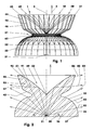
- FIG. 1 shows a wire model of a light-emitting diode (20) as an example of a lighting unit (10).
- the light emitting diode (20) comprises a non-glare light source (21), e.g. a light emitting chip (21) and a light distribution body (31).
- the electrical connections of the light-emitting diode (20) are not shown here.
- FIG. 2 shows a section through this light-emitting diode (20), the sectional plane of this representation comprising the optical axis (5).
- the optical axis (5) of the lighting unit (10), for example, is aligned normal to the light-emitting chip (21) and penetrates the light distribution body (31).
- the latter is arranged rotationally symmetrical to the optical axis (5) in this embodiment. It can also be square, rectangular, elliptical, etc. formed in the front view.
- the light source is arranged in the center, so that the zero-degree direction (2) originates at the light-emitting chip (21). It is oriented here parallel to the optical axis (5) in the direction of the end face (43) of the light distribution body (31), which faces away from the light-emitting chip (21).
- the zero-degree direction (2) points upwards.
- the light-emitting chip (21) is embedded in the lower region of the light distribution body (31), such that the light distribution body (31) bears against and surrounds the light-emitting chip (21).
- the light distribution body (31) has along the optical axis (5) above the non-glimmering light source (21) e.g. a length of 3 millimeters. Its maximum diameter in a plane normal to the optical axis (5) is for example 5 millimeters. The length of the Lichtverteil stressess (31) is thus less than 70% of its maximum diameter in this embodiment.
- the light distribution body (31) may have greater or smaller than the dimensions mentioned. Thus, the diameter of the light distribution body (31) may be e.g. between 3 millimeters and 8 millimeters.
- the light distribution body (31) comprises two sections (32, 42) of at least approximately the same length which are arranged one behind the other in the zero-degree direction (2) and are interconnected by means of a transition region (61) formed as a constriction (62).
- the lower portion (32) shown in Figure 1 has at least approximately the shape of a semi-ellipsoid (33) whose center and section plane is normal to the optical axis (5).
- On the lower portion (32) sits as upper portion (42) e.g. a truncated cone (44) that widens in the zero-degree direction (2).
- the end face (43) of the Lichtverteil emotionss (31) has a central recess (49).
- the diameter of the constriction (62) in this embodiment is 45% of the maximum diameter of the Lichtverteil emotionss (31).
- FIG. 3 In the sectional view of Figure 2 of the semi-ellipsoid (33) is shown as a semi-ellipse (34).
- the horizontal central axis of the semi-ellipse (34) is formed in this embodiment by two aligned semi-major axes (36), of which only one shown in FIG is.
- These large semiaxes (36) lie, for example, parallel to the light-emitting chip (21) and are offset from the light-emitting chip (21) by, for example, 1% of the diameter of the light distribution body (31) in the zero-degree direction (2).
- the imaginary small semi-axis of the half ellipse (34) lies on the optical axis (5).
- the radius of the Schmieg Vietnamese semi-axes (36) lies the midpoints (38) of Schmieg Vietnamese semi-axes (36).
- the radius of the Schmieg Vietnamesee is for example between 40% and 90% of the length of the major half-axes (36) of the semi-ellipse (34). In the illustration of Figure 2, the radius is 60% of this length.
- the half ellipse (34) may have the shape of an oval.
- the Schmieg Vietnamese may also comprise a portion of a semi-ellipse (34), for example a light distribution body (31) which is a segment of a body rotationally symmetrical to the optical axis (5).
- the half ellipse (34) is e.g. tangentially in the example formed as a groove throat constriction (62). Their radius is e.g. 2% of the length of the semi-ellipse (34).
- the maximum diameter of the truncated cone (44) is for example 90% of the maximum diameter of the Lichtverteil stresses (31).
- Its lateral surface (46) has an upper (47) and a lower portion (48).
- the lateral surface (46) is inclined here by 20 degrees to the optical axis (5).
- the length of this region (47), measured parallel to the optical axis (5), is for example 35% of the length of the Lichtverteil stressess (31).
- the inclination of the lateral surface (46) to the optical axis (5) 60 degrees.
- the lateral surface (46) can also be constructed in steps. The steps then include, for example, a plurality of surfaces offset from one another and inclined at 20 degrees to the optical axis.
- the depression (49) of the light-emitting chip (21) facing away from the end face (43) is funnel-shaped and tapers in the direction of the light-emitting chip (21). She runs to a peak (52). Its depth is for example 48% of the length of Lichtverteilianus (31). The largest diameter of the recess (49) in this embodiment is 80% of the maximum diameter of Lichtverteil stressess (31).
- the generatrix of the boundary surface (51) of the recess (49) is a parabola in this embodiment, cf. Figure 2.
- the focal point of the parabola is here in the e.g. as a punctiform light emitting chip (21). Instead of a parabola, the generatrix of the depression (49) can also be another continuous or sectionally continuous geometric curve.
- the production of the light emitting diode (20) takes place, for example by injection molding in two steps.
- the material used in the injection molding process in both steps is, for example, a highly transparent thermoplastic, for example modified polymethyl methacrylimide (PMMI), polysulfone (PSU), silicone, etc.
- PMMI modified polymethyl methacrylimide
- PSU polysulfone
- silicone etc.
- the light-emitting chip (21) is surrounded by an electronic protective device, not shown here.
- this is then overmolded to form the Lichtverteil stressess (31).
- the light-emitting diode (20) can also be produced in a single work step.
- the shape the surface of Lichtverteil emotionss (31) are additionally changed by means of a forming process.
- the light emitting chip (21) which is assumed to be punctiform, emits light as a Lambertian radiator at least approximately into a half space.
- FIG. 2 shows, by way of example, individual light beams (82-86) offset by 15 degrees from one another.
- Light (82-84) which is at an angle between e.g. 85 degrees and 35 degrees to the optical axis (5) is emitted hits the interface (35) of the semi-ellipsoid (33).
- the angle of 85 degrees here is the angle of the imaginary ray of light that passes through the center (38) of Schmiegnikes.
- the light (82-84) with the normal at the point of impact includes an angle smaller than the critical angle of total reflection.
- This critical angle is here, for example, 43 degrees.
- the light (82-84) passes through the interface (35).
- the refractive index is 1.635.
- the light emitted from the light-emitting chip (21) in the aforementioned angular segment now exits in an angular segment of, for example, 62 degrees to 85 degrees to the optical axis (5) into the environment (1).
- the boundary surface (35) of the semi-ellipsoid (33) thus acts as a converging lens for the light emitted by the light-emitting chip (21).
- a high light intensity results in this segment.
- the interface (35) of the hemi-ellipsoid (33) may be designed in the manner of a Fresnel lens.
- it may comprise individual, designed as Fresnel elements circumferential rings.
- Theoretical envelope of such a Fresnel lens is the above-described condenser lens.
- the light (85, 86) impinges on this boundary surface (51) at an angle to the normal at the point of impact that is greater than the critical angle of total reflection.
- the boundary surface (51) forms for the incident light (85, 86) a total reflection surface (91) at which the incident light (85, 86) in the direction of the lateral surface (46) is reflected.
- a small portion of the light emitted by the light-emitting chip (21) passes through the tip (52) of the depression (49) into the environment (1).
- the total reflection surface (91) may for example be composed of individual surface elements.
- the connecting line of the surface element to the light-emitting chip (21) then encloses with the normal in this surface element an angle which is greater than the critical angle of total reflection.
- the boundary surface (51) of the recess (49) may also be mirrored. It can be larger than the total reflection area (91).
- the light (85, 86) reflected at the total reflection surface (91) is at least approximately parallel to one another in this exemplary embodiment. It impinges on the lateral surface (46) at an angle to the normal at the point of impact which is smaller than the critical angle of total reflection. When passing through the lateral surface (46), which forms a refraction surface (93), it is refracted away from the solder. In the exemplary embodiment shown here, the light (85, 86) enters at an angle of 75 degrees to the optical axis (5) Environment (1).
- the lateral surface (46) can also be arranged such that the reflected light (85, 86) penetrates it without refraction.
- the light emitted by the light-emitting chip (21) is deflected.
- the maximum of the light intensity is for example in a range of 75 degrees to the optical axis (5). Due to the homogeneous material of the Lichtverteil stressess (31) and the low refractive losses, the lighting unit described here (10) has a high efficiency.
- the transition region (61) between the lower section (32) and the upper section (42) of the light distribution body (31) is defined, for example, such that a light beam tangent to the transition region (61) in the representation of FIG. 2 at the upper end of the boundary surface (FIG. 51).
- the imaginary circumferential line at the upper end of the boundary surface (51) is determined, inter alia, by the refractive index and the desired light exit angle of the lower section (32).
- n is the refractive index of the material of the lower portion (32).
- the origin of the angle alpha is the point of passage of the light beam through the interface (35) of the lower portion (32).
- the origin of the critical angle (alpha + x) is the light-emitting chip (21).
- the limit angle of the boundary surface (51) thus determined also determines the lateral surface (46) of the upper section (42).
- FIG. 3 shows the polar light distribution diagram for the lighting unit (10) shown in FIGS. 1 and 2.
- Radiant (102) the radiation angles are shown, wherein the upward pointing direction is the zero-degree direction (2).
- concentric circles (103) are arranged. These show from the center (101) outwardly decreasing luminous intensity values, e.g. in candelas per kilo.
- the light emerging from the light distribution body (31) thus has a maximum intensity in a region around 75 degrees on both sides of the zero-degree direction (2). The intensity decreases both at smaller angles and at larger angles.
- the center plane of the half-ellisoid (33) is shifted away from the light-emitting chip (21) in the zero-degree direction (2).
- the angle of inclination of at least the upper region (47) of the lateral surface (46) to the optical axis (5) can be increased.
- the median plane of the semiellipsoid (33) can be arranged closer to the light-emitting chip (21) become.
- the inclination angle, for example, of the upper region (47) of the lateral surface (46) to the optical axis (5) can be reduced.
- the distance of the center points (38) of the Schmieg Vietnamesee to the light-emitting chip (21) can be made large.
- the centers (38) of the flywheel circuits can be placed close to the light-emitting chip (21).
- FIG. 4 shows a lighting unit (10) with a light-emitting diode (20) and a light-emitting diode (20) optically downstream reflector (70) is shown.
- the light-emitting diode (20) largely corresponds to the light-emitting diode (20) shown in FIGS. 1 and 2. In the embodiment shown here, however, the refractive index of the material of the Lichtverteil stressess (31), for example, 1.4.
- the light (81-87) emerging from the light-emitting diode (20) passes over a segment of 50 degrees to 90 degrees to the optical axis (5).
- the reflector (70) is concave and constructed, for example, coaxially to the optical axis (5). In its center sits the LED (20). It comprises here two reflection areas (71, 72). An inner cone-shaped region (71) is surrounded by an outer, eg parabolic, region (72). The conical region (71) is inclined here, for example, by 45 degrees to the optical axis (5).
- the light beam (81) is shown, which passes through the center (38) of the semi-circle of the semi-ellipse (34). This light beam (81) strikes normal on the interface (35) and is not broken when passing through the interface (35).
- the inclination of the light beam (81) exiting into the environment (1) to the optical axis (5) is for example 85 degrees.
- the light beam (87) is further shown, which affects the constriction (62).
- This light beam (87) is the light beam (87) with the greatest inclination angle with respect to the optical axis (5), which impinges on the total reflection surface (91). It is reflected at the light emitting chip (21) remote end (92) of the total reflection surface (91) in the direction of the lateral surface (46) and penetrates, for example, without refraction, the lateral surface (46).
- the inclination of the light beam (87) exiting into the environment (1) to the optical axis (5) is for example 90 degrees.
- the two described light beams (81, 87) intersect in the sectional representation of FIG. 4 at a point (89) which lies, for example, on the reflector (70).
- the conical region (71) merges into the parabolic region (72).
- this point (89) is a point of a line which, for example, has a constant distance from the light distribution body (31).
- this line is a circle whose center lies, for example, on the optical axis (5).
- the transition of the two reflector regions (71, 72) may have a greater distance from the light-emitting diode (20) than the line (89).
- the individual light beams (85, 86) are now, for example, parallel to one another.
- the reflector (70) can also be designed with a single conical or a single arched area. Hereby, for example, a diffused portion of the light emitted by the lighting unit (10) can be generated in a targeted manner. It is also conceivable to form the reflector (70) parabolically in the basic form. Pillow-like elevations and / or depressions are then arranged on the reflector surface, for example.
- the entire light emerging from the light-emitting diode (20) is distributed on a large surface of the reflector (70) and reflected there. Minor inaccuracies of the coating of the reflector (70) do not affect the light emitted by the lighting unit (10).
- the inserted reflector (70) can thus be manufactured in a diameter range, in which, for example, the coating can be produced safely and accurately.
- the lighting unit (10) is thus compact and highly efficient.
- the lighting unit (10) can also be designed such that in a view from the end face (43) of the reflector (70) and / or the Lichtverteilève (31) is a segment of a rotationally symmetrical body. A square, rectangular, etc. limited by a polygon, etc. shape of the Lichtverteil stressess (31) and / or the reflector (70) is conceivable.
- the light emitting diode (20) may also comprise a plurality of light emitting chips (21).
Abstract
Description
Die Erfindung betrifft eine Leuchteinheit mit einer mindestens eine nichtglimmende Lichtquelle umfassenden Leuchtdiode und mit einem der nichtglimmenden Lichtquelle optisch nachgeschalteten Lichtverteilkörper, wobei der Lichtverteilkörper mindestens zwei in einer zumindest annähernd parallel zur optischen Achse der Leuchteinheit orientierten Null-Grad-Richtung hintereinander angeordnete Abschnitte aufweist, wobei die der nichtglimmenden Lichtquelle abgewandte Stirnseite des Lichtverteilkörpers eine Einsenkung hat und wobei jede Begrenzungsfläche der Einsenkung eine Totalreflexionsfläche für das von der nichtglimmenden Lichtquelle emittierte Licht umfasst.The invention relates to a lighting unit comprising a light emitting diode comprising at least one non-glimmering light source and light distribution body optically connected to a non-glimmering light source, wherein the light distribution body has at least two sections arranged one behind the other in a zero-degree direction oriented at least approximately parallel to the optical axis of the lighting unit the end face of the light distribution body facing away from the non-glimmering light source has a depression and wherein each boundary surface of the depression comprises a total reflection surface for the light emitted by the non-glimmering light source.
Die optische Achse einer Leuchteinheit ist beispielsweise die geometrische Mittellinie des von der Leuchteinheit ausgesandten Lichts. In einem polaren Lichtverteilungsdiagramm für die Leuchteinheit ist die Lichtquelle im Zentrum angeordnet. Um die Lichtquelle herum ist in diesem Diagramm die Intensität des Lichtes in den einzelnen Segmenten des Vollkreises aufgetragen. Die Leuchteinheit ist hierfür meist in einer Vorzugsstellung im Diagramm dargestellt. Beispielsweise wird der Abschnitt der optischen Achse, der in der Abstrahlrichtung der Lichtquelle orientiert ist, in die Null-Grad-Richtung des Diagramms eingezeichnet. Im Folgenden wird daher als Null-Grad-Richtung der Leuchteinheit die von der Lichtquelle ausgehende Richtung bezeichnet, die zumindest annähernd parallel zur optischen Achse orientiert ist.The optical axis of a lighting unit is, for example, the geometric center line of the light emitted by the lighting unit. In a polar light distribution diagram for the lighting unit, the light source is arranged in the center. Around the light source, the intensity of the light in the individual segments of the full circle is plotted in this diagram. The lighting unit is this usually shown in a preferred position in the diagram. For example, the portion of the optical axis oriented in the emission direction of the light source is drawn in the zero-degree direction of the diagram. In the following, therefore, the zero-degree direction of the lighting unit is the direction emanating from the light source, which is oriented at least approximately parallel to the optical axis.
Aus der
Der vorliegenden Erfindung liegt daher die Problemstellung zugrunde, eine kompakte Leuchteinheit mit einer hohen optischen Effizienz zu entwickeln.The present invention is therefore based on the problem to develop a compact lighting unit with a high optical efficiency.
Diese Problemstellung wird mit den Merkmalen des Hauptanspruches gelöst. Dazu ist der Lichtverteilkörper Teil der Leuchtdiode. Der an der nichtglimmenden Lichtquelle anliegende Abschnitt des Lichtverteilkörpers hat zumindest in einer Schnittebene, die die optische Achse umfasst, als Hüllkurve einen Ellipsenabschnitt. Zumindest eine große Halbachse dieser Ellipse ist in der Null-Grad-Richtung versetzt zur nichtglimmenden Lichtquelle angeordnet. Außerdem beträgt der Radius des Schmiegkreises am Endpunkt der großen Halbachse zwischen 30 % und 90 % der Länge der großen Halbachse.This problem is solved with the features of the main claim. For this purpose, the light distribution body is part of the light emitting diode. The section of the light distribution body resting against the non-glimmering light source has as an envelope an ellipse section at least in a sectional plane which comprises the optical axis. At least one major half-axis of this ellipse is offset in the zero-degree direction from the non-glowing light source. In addition, the radius of the semi-circle at the end of the semi-major axis is between 30% and 90% of the length of the semi-major axis.
Weitere Einzelheiten der Erfindung ergeben sich aus den Unteransprüchen und der nachfolgenden Beschreibung schematisch dargestellter Ausführungsformen.
- Figur 1:
- Leuchteinheit mit Leuchtdiode;
- Figur 2:
- Schnitt durch die
Figur 1; - Figur 3:
- Lichtverteilungsdiagramm der Leuchteinheit nach
Figur 1; - Figur 4:
- Leuchteinheit mit Leuchtdiode und Reflektor.
- FIG. 1:
- Light unit with LED;
- FIG. 2:
- Section through the figure 1;
- FIG. 3:
- Light distribution diagram of the lighting unit of Figure 1;
- FIG. 4:
- Light unit with LED and reflector.
Die Figur 1 zeigt als Beispiel einer Leuchteinheit (10) ein Drahtmodell einer Leuchtdiode (20). Die Leuchtdiode (20) umfasst eine nichtglimmende Lichtquelle (21), z.B. einen lichtemittierenden Chip (21) und einen Lichtverteilkörper (31). Die elektrischen Anschlüsse der Leuchtdiode (20) sind hier nicht dargestellt. In der Figur 2 ist ein Schnitt durch diese Leuchtdiode (20) dargestellt, wobei die Schnittebene dieser Darstellung die optische Achse (5) umfasst.FIG. 1 shows a wire model of a light-emitting diode (20) as an example of a lighting unit (10). The light emitting diode (20) comprises a non-glare light source (21), e.g. a light emitting chip (21) and a light distribution body (31). The electrical connections of the light-emitting diode (20) are not shown here. FIG. 2 shows a section through this light-emitting diode (20), the sectional plane of this representation comprising the optical axis (5).
Die optische Achse (5) der Leuchteinheit (10) ist beispielsweise normal zum lichtemittierenden Chip (21) ausgerichtet und durchdringt den Lichtverteilkörper (31). Letzterer ist in diesem Ausführungsbeispiel rotationssymmetrisch zur optischen Achse (5) angeordnet. Er kann in der Stirnansicht aber auch quadratisch, rechteckig, elliptisch, etc. ausgebildet sein. Im Lichtverteilungsdiagramm ist die Lichtquelle im zentrum angeordnet, so dass die Null-Grad-Richtung (2) am lichtemittierenden Chip (21) entspringt. Sie ist hier parallel zur optischen Achse (5) in Richtung der Stirnseite (43) des Lichtverteilkörpers (31) orientiert, die dem lichtemittierenden Chip (21) abgewandt ist. In der Darstellung der Figuren 1 - 4 zeigt die Null-Grad-Richtung (2) nach oben.The optical axis (5) of the lighting unit (10), for example, is aligned normal to the light-emitting chip (21) and penetrates the light distribution body (31). The latter is arranged rotationally symmetrical to the optical axis (5) in this embodiment. It can also be square, rectangular, elliptical, etc. formed in the front view. In the light distribution diagram, the light source is arranged in the center, so that the zero-degree direction (2) originates at the light-emitting chip (21). It is oriented here parallel to the optical axis (5) in the direction of the end face (43) of the light distribution body (31), which faces away from the light-emitting chip (21). In the illustration of FIGS. 1-4, the zero-degree direction (2) points upwards.
Der lichtemittierende Chip (21) ist in den Figuren 1 und 2 in den in den unteren Bereich des Lichtverteilkörpers (31) eingebettet, so dass der Lichtverteilkörper (31) am lichtemittierenden Chip (21) anliegt und diesen umgibt.In FIGS. 1 and 2, the light-emitting chip (21) is embedded in the lower region of the light distribution body (31), such that the light distribution body (31) bears against and surrounds the light-emitting chip (21).
Der Lichtverteilkörper (31) hat entlang der optischen Achse (5) oberhalb der nichtglimmenden Lichtquelle (21) z.B. eine Länge von 3 Millimetern. Sein maximaler Durchmesser in einer Ebene normal zur optischen Achse (5) beträgt beispielsweise 5 Millimeter. Die Länge des Lichtverteilkörpers (31) ist somit in diesem Ausführungsbeispiel kleiner als 70 % seines maximalen Durchmessers. Der Lichtverteilkörper (31) kann grö-ßere oder kleinere als die genannten Abmessungen aufweisen. So kann der Durchmesser des Lichtverteilkörpers (31) z.B. zwischen 3 Millimeter und 8 Millimeter betragen.The light distribution body (31) has along the optical axis (5) above the non-glimmering light source (21) e.g. a length of 3 millimeters. Its maximum diameter in a plane normal to the optical axis (5) is for example 5 millimeters. The length of the Lichtverteilkörpers (31) is thus less than 70% of its maximum diameter in this embodiment. The light distribution body (31) may have greater or smaller than the dimensions mentioned. Thus, the diameter of the light distribution body (31) may be e.g. between 3 millimeters and 8 millimeters.
Der Lichtverteilkörper (31) umfasst zwei in der Null-Grad-Richtung (2) hintereinander angeordnete Abschnitte (32, 42) zumindest annähernd gleicher Länge, die mittels eines als Einschnürung (62) ausgebildeten Übergangsbereichs (61) miteinander verbunden sind. Der in der Figur 1 dargestellte untere Abschnitt (32) hat zumindest annähernd die Gestalt eines Halbellipsoiden (33), dessen Mittel- und Schnittebene normal zur optischen Achse (5) liegt. Auf dem unteren Abschnitt (32) sitzt als oberer Abschnitt (42) z.B. ein Kegelstumpf (44), der sich in der Null-Grad-Richtung (2) aufweitet. Die Stirnseite (43) des Lichtverteilkörpers (31) hat eine zentrale Einsenkung (49). Der Durchmesser der Einschnürung (62) beträgt in diesem Ausführungsbeispiel 45 % des maximalen Durchmessers des Lichtverteilkörpers (31).The light distribution body (31) comprises two sections (32, 42) of at least approximately the same length which are arranged one behind the other in the zero-degree direction (2) and are interconnected by means of a transition region (61) formed as a constriction (62). The lower portion (32) shown in Figure 1 has at least approximately the shape of a semi-ellipsoid (33) whose center and section plane is normal to the optical axis (5). On the lower portion (32) sits as upper portion (42) e.g. a truncated cone (44) that widens in the zero-degree direction (2). The end face (43) of the Lichtverteilkörpers (31) has a central recess (49). The diameter of the constriction (62) in this embodiment is 45% of the maximum diameter of the Lichtverteilkörpers (31).
In der Schnittdarstellung der Figur 2 ist der Halbellipsoid (33) als Halbellipse (34) dargestellt. Die hier waagerecht liegende Mittelachse der Halbellipse (34) wird in diesem Ausführungsbeispiel gebildet durch zwei miteinander fluchtende große Halbachsen (36), von denen in der Figur 2 nur eine dargestellt ist. Diese großen Halbachsen (36) liegen z.B. parallel zum lichtemittierenden Chip (21) und sind zum lichtemittierenden Chip (21) beispielsweise um 1 % des Durchmessers des Lichtverteilkörpers (31) in der Null-Grad-Richtung (2) versetzt. Die gedachte kleine Halbachse der Halbellipse (34) liegt auf der optischen Achse (5).In the sectional view of Figure 2 of the semi-ellipsoid (33) is shown as a semi-ellipse (34). The horizontal central axis of the semi-ellipse (34) is formed in this embodiment by two aligned semi-major axes (36), of which only one shown in FIG is. These large semiaxes (36) lie, for example, parallel to the light-emitting chip (21) and are offset from the light-emitting chip (21) by, for example, 1% of the diameter of the light distribution body (31) in the zero-degree direction (2). The imaginary small semi-axis of the half ellipse (34) lies on the optical axis (5).
Auf den großen Halbachsen (36) liegen die Mittelpunkte (38) der Schmiegkreise. Diese Schmiegkreise tangieren die Halbellipse (34) zumindest in den Endpunkten (37) der großen Halbachsen (36). Der Radius der Schmiegkreise beträgt beispielsweise zwischen 40 % und 90 % der Länge der großen Halbachsen (36) der Halbellipse (34). In der Darstellung der Figur 2 beträgt der Radius 60 % dieser Länge. Gegebenenfalls kann die Halbellipse (34) die Gestalt eines Ovals haben. Der Schmiegkreis tangiert dann die Halbellipse (34) entlang eines Viertelkreises. Die den unteren Abschnitt (32) begrenzende Linie kann auch einen Abschnitt einer Halbellipse (34) umfassen, beispielsweise bei einem Lichtverteilkörper (31), der ein Segment eines zur optischen Achse (5) rotationssymmetrischen Körpers ist.On the large semi-axes (36) lie the midpoints (38) of Schmiegkreise. These Schmiegkreise affect the half ellipse (34) at least in the end points (37) of the major semi-axes (36). The radius of the Schmiegkreise is for example between 40% and 90% of the length of the major half-axes (36) of the semi-ellipse (34). In the illustration of Figure 2, the radius is 60% of this length. Optionally, the half ellipse (34) may have the shape of an oval. The Schmiegkreis then affects the Halbellipse (34) along a quarter circle. The line delimiting the lower portion (32) may also comprise a portion of a semi-ellipse (34), for example a light distribution body (31) which is a segment of a body rotationally symmetrical to the optical axis (5).
Die Halbellipse (34) geht z.B. tangential in die beispielsweise als Hohlkehle ausgebildete Einschnürung (62) über. Ihr Radius beträgt z.B. 2 % der Länge der Halbellipse (34).The half ellipse (34) is e.g. tangentially in the example formed as a groove throat constriction (62). Their radius is e.g. 2% of the length of the semi-ellipse (34).
Der maximale Durchmesser des Kegelstumpfs (44) beträgt beispielsweise 90 % des maximalen Durchmessers des Lichtverteilkörpers (31). Seine Mantelfläche (46) hat einen oberen (47) und einen unteren Bereich (48). Im oberen Bereich (47) ist die Mantelfläche (46) hier um 20 Grad zur optischen Achse (5) geneigt. Die Länge dieses Bereiches (47), parallel zur optischen Achse (5) gemessen, beträgt z.B. 35 % der Länge des Lichtverteilkörpers (31). Im unteren Bereich (48) beträgt in diesem Ausführungsbeispiel die Neigung der Mantelfläche (46) zur optischen Achse (5) 60 Grad. Die Mantelfläche (46) kann auch stufenförmig aufgebaut sein. Die Stufen umfassen dann z.B. mehrere Flächen, die versetzt zueinander sind und 20 Grad zur optischen Achse geneigt sind.The maximum diameter of the truncated cone (44) is for example 90% of the maximum diameter of the Lichtverteilkörpers (31). Its lateral surface (46) has an upper (47) and a lower portion (48). In the upper region (47), the lateral surface (46) is inclined here by 20 degrees to the optical axis (5). The length of this region (47), measured parallel to the optical axis (5), is for example 35% of the length of the Lichtverteilkörpers (31). In the lower area (48) is in this Embodiment, the inclination of the lateral surface (46) to the optical axis (5) 60 degrees. The lateral surface (46) can also be constructed in steps. The steps then include, for example, a plurality of surfaces offset from one another and inclined at 20 degrees to the optical axis.
Die Einsenkung (49) der dem lichtemittierenden Chip (21) abgewandten Stirnseite (43) ist trichterförmig ausgebildet und verjüngt sich in Richtung des lichtemittierenden Chips (21). Sie läuft auf eine Spitze (52) zu. Ihre Tiefe beträgt beispielsweise 48 % der Länge des Lichtverteilkörpers (31). Der größte Durchmesser der Einsenkung (49) beträgt in diesem Ausführungsbeispiel 80 % des maximalen Durchmessers des Lichtverteilkörpers (31). Die Erzeugende der Begrenzungsfläche (51) der Einsenkung (49) ist in diesem Ausführungsbeispiel eine Parabel, vgl. Figur 2. Der Brennpunkt der Parabel liegt hier in dem z.B. als punktförmig angenommenen lichtemittierenden Chip (21). Anstatt einer Parabel kann die Erzeugende der Einsenkung (49) auch eine andere stetige oder abschnittsweise stetige geometrische Kurve sein.The depression (49) of the light-emitting chip (21) facing away from the end face (43) is funnel-shaped and tapers in the direction of the light-emitting chip (21). She runs to a peak (52). Its depth is for example 48% of the length of Lichtverteilkörpers (31). The largest diameter of the recess (49) in this embodiment is 80% of the maximum diameter of Lichtverteilkörpers (31). The generatrix of the boundary surface (51) of the recess (49) is a parabola in this embodiment, cf. Figure 2. The focal point of the parabola is here in the e.g. as a punctiform light emitting chip (21). Instead of a parabola, the generatrix of the depression (49) can also be another continuous or sectionally continuous geometric curve.
Die Herstellung der Leuchtdiode (20) erfolgt beispielsweise im Spritzgussverfahren in zwei Arbeitsschritten. Der beim Spritzgussverfahren in beiden Arbeitsschritten eingesetzte Werkstoff ist beispielsweise ein hochtransparenter Thermoplast, z.B. modifiziertes Polymethylmethacrylimid (PMMI), Polysulfon (PSU), Silikon, etc. Im ersten Arbeitsschritt wird der lichtemittierende Chip (21) mit einem hier nicht dargestellten Elektronikschutzkörper umgeben. Im zweiten Arbeitsschritt wird dieser dann zur Bildung des Lichtverteilkörpers (31) umspritzt. Es ergibt sich somit ein homogener Lichtverteilkörper (31), der unmittelbar am lichtemittierenden Chip (21) anliegt. Die Leuchtdiode (20) kann aber auch in einem einzigen Arbeitsschritt hergestellt werden. Gegebenenfalls kann die Gestalt der Oberfläche des Lichtverteilkörpers (31) zusätzlich mittels eines Umformverfahrens verändert werden.The production of the light emitting diode (20) takes place, for example by injection molding in two steps. The material used in the injection molding process in both steps is, for example, a highly transparent thermoplastic, for example modified polymethyl methacrylimide (PMMI), polysulfone (PSU), silicone, etc. In the first step, the light-emitting chip (21) is surrounded by an electronic protective device, not shown here. In the second step, this is then overmolded to form the Lichtverteilkörpers (31). This results in a homogeneous Lichtverteilkörper (31), which rests directly on the light-emitting chip (21). However, the light-emitting diode (20) can also be produced in a single work step. Optionally, the shape the surface of Lichtverteilkörpers (31) are additionally changed by means of a forming process.
Beim Betrieb der Leuchtdiode (20) emittiert der hier als punktförmig angenommene lichtemittierende Chip (21) Licht als Lambert'scher Strahler zumindest annähernd in einen Halbraum. In der Figur 2 sind beispielhaft einzelne, um 15 Grad zueinander versetzte Lichtstrahlen (82 - 86) dargestellt. Licht (82 - 84) das unter einem Winkel zwischen z.B. 85 Grad und 35 Grad zur optischen Achse (5) emittiert wird, trifft auf die Grenzfläche (35) des Halbellipsoiden (33). Der Winkel von 85 Grad ist hier der Winkel des gedachten Lichtstrahls, der durch den Mittelpunkt (38) des Schmiegkreises geht. Beim Auftreffen auf die Grenzfläche (35) schließt das Licht (82 - 84) mit der Normalen im Auftreffpunkt einen Winkel ein, der kleiner ist als der Grenzwinkel der Totalreflexion. Dieser Grenzwinkel ist hier beispielsweise 43 Grad. Das Licht (82 - 84) tritt durch die Grenzfläche (35) hindurch. Beim Übergang vom optisch dichteren Werkstoff des Lichtverteilkörpers (31) in die optisch dünnere Umgebung (1), z.B. Luft, wird das Licht (82 - 84) vom Lot weg gebrochen. In dem hier dargestellten Ausführungsbeispiel beträgt die Brechungszahl 1,635. Das in dem oben angegebenen Winkelsegment vom lichtemittierenden Chip (21) emittierte Licht tritt nun in einem Winkelsegment von beispielsweise 62 Grad bis 85 Grad zur optischen Achse (5) in die Umgebung (1) aus. Die Grenzfläche (35) des Halbellipsoiden (33) wirkt somit als Sammellinse für das vom lichtemittierenden Chip (21) emittierte Licht. In einem polar dargestellten Lichtverteilungsdiagramm, vgl. Figur 3, ergibt sich in diesem Segment eine hohe Lichtstärke.During operation of the light emitting diode (20), the light emitting chip (21), which is assumed to be punctiform, emits light as a Lambertian radiator at least approximately into a half space. FIG. 2 shows, by way of example, individual light beams (82-86) offset by 15 degrees from one another. Light (82-84) which is at an angle between e.g. 85 degrees and 35 degrees to the optical axis (5) is emitted hits the interface (35) of the semi-ellipsoid (33). The angle of 85 degrees here is the angle of the imaginary ray of light that passes through the center (38) of Schmiegkreises. Upon impact with the interface (35), the light (82-84) with the normal at the point of impact includes an angle smaller than the critical angle of total reflection. This critical angle is here, for example, 43 degrees. The light (82-84) passes through the interface (35). In the transition from the optically denser material of the Lichtverteilkörpers (31) in the optically thinner environment (1), e.g. Air, the light (82-84) is broken away from the solder. In the embodiment shown here, the refractive index is 1.635. The light emitted from the light-emitting chip (21) in the aforementioned angular segment now exits in an angular segment of, for example, 62 degrees to 85 degrees to the optical axis (5) into the environment (1). The boundary surface (35) of the semi-ellipsoid (33) thus acts as a converging lens for the light emitted by the light-emitting chip (21). In a polarized light distribution diagram, cf. FIG. 3, a high light intensity results in this segment.
Die Grenzfläche (35) des Halbellipsoiden (33) kann in der Art einer Fresnellinse gestaltet sein. So kann sie einzelne, als Fresnelelemente ausgebildete umlaufende Ringe umfassen. Die theoretische Hüllgestalt einer solchen Fresnellinse ist die oben beschriebene Sammellinse.The interface (35) of the hemi-ellipsoid (33) may be designed in the manner of a Fresnel lens. Thus, it may comprise individual, designed as Fresnel elements circumferential rings. The Theoretical envelope of such a Fresnel lens is the above-described condenser lens.
Licht (85, 86), das vom lichtemittierenden Chip (21) unter einem Winkel zur optischen Achse (5) emittiert wird, der kleiner ist als 35 Grad, gelangt an die Begrenzungsfläche (51) der Einsenkung (49). Das Licht (85, 86) trifft auf diese Begrenzungsfläche (51) in einem Winkel zur Normalen im Auftreffpunkt auf, der größer ist als der Grenzwinkel der Totalreflexion. Die Begrenzungsfläche (51) bildet für das auftreffende Licht (85, 86) eine Totalreflexionsfläche (91), an der das auftreffende Licht (85, 86) in Richtung der Mantelfläche (46) reflektiert wird. Ein kleiner Anteil des vom lichtemittierenden Chip (21) emittierten Lichts tritt durch die Spitze (52) der Einsenkung (49) hindurch in die Umgebung (1).Light (85, 86) emitted from the light-emitting chip (21) at an angle to the optical axis (5) smaller than 35 degrees reaches the boundary surface (51) of the recess (49). The light (85, 86) impinges on this boundary surface (51) at an angle to the normal at the point of impact that is greater than the critical angle of total reflection. The boundary surface (51) forms for the incident light (85, 86) a total reflection surface (91) at which the incident light (85, 86) in the direction of the lateral surface (46) is reflected. A small portion of the light emitted by the light-emitting chip (21) passes through the tip (52) of the depression (49) into the environment (1).
Die Totalreflexionsfläche (91) kann beispielsweise aus einzelnen Flächenelementen zusammengesetzt sein. Die Verbindungslinie des Flächenelementes zum lichtemittierenden Chip (21) schließt dann mit der Normalen in diesem Flächenelement einen Winkel ein, der größer ist als der Grenzwinkel der Totalreflexion. Die Begrenzungsfläche (51) der Einsenkung (49) kann auch verspiegelt sein. Sie kann größer sein als die Totalreflexionsfläche (91).The total reflection surface (91) may for example be composed of individual surface elements. The connecting line of the surface element to the light-emitting chip (21) then encloses with the normal in this surface element an angle which is greater than the critical angle of total reflection. The boundary surface (51) of the recess (49) may also be mirrored. It can be larger than the total reflection area (91).
Das an der Totalreflexionsfläche (91) reflektierte Licht (85, 86) ist in diesem Ausführungsbeispiel zueinander zumindest annähernd parallel. Es trifft auf die Mantelfläche (46) in einem Winkel zur Normalen im Auftreffpunkt auf, der kleiner ist als der Grenzwinkel der Totalreflexion. Beim Durchtritt durch die Mantelfläche (46), die eine Refraktionsfläche (93) bildet, wird es vom Lot weg gebrochen. In dem hier dargestellten Ausführungsbeispiel tritt das Licht (85, 86) unter einem Winkel von 75 Grad zur optischen Achse (5) in die Umgebung (1). Die Mantelfläche (46) kann auch so angeordnet sein, dass das reflektierte Licht (85, 86) sie ohne Brechung durchdringt.The light (85, 86) reflected at the total reflection surface (91) is at least approximately parallel to one another in this exemplary embodiment. It impinges on the lateral surface (46) at an angle to the normal at the point of impact which is smaller than the critical angle of total reflection. When passing through the lateral surface (46), which forms a refraction surface (93), it is refracted away from the solder. In the exemplary embodiment shown here, the light (85, 86) enters at an angle of 75 degrees to the optical axis (5) Environment (1). The lateral surface (46) can also be arranged such that the reflected light (85, 86) penetrates it without refraction.
Das aus dem oberen Abschnitt (42) austretende Licht (85, 86) überlagert sich mit dem Licht (82 - 84), das aus dem unteren Abschnitt (32) des Lichtverteilkörpers (31) austritt. Das vom lichtemittierenden Chip (21) emittierte Licht wird umgelenkt. Das Maximum der Lichtintensität liegt beispielsweise in einem Bereich um 75 Grad zur optischen Achse (5). Aufgrund des homogenen Werkstoffs des Lichtverteilkörpers (31) und der geringen Brechungsverluste hat die hier beschriebene Leuchteinheit (10) einen hohen Wirkungsgrad.The light (85, 86) emerging from the upper section (42) overlaps with the light (82-84) emerging from the lower section (32) of the light distribution body (31). The light emitted by the light-emitting chip (21) is deflected. The maximum of the light intensity is for example in a range of 75 degrees to the optical axis (5). Due to the homogeneous material of the Lichtverteilkörpers (31) and the low refractive losses, the lighting unit described here (10) has a high efficiency.
Der Übergangsbereich (61) zwischen dem unteren Abschnitt (32) und dem oberen Abschnitt (42) des Lichtverteilkörpers (31) ist beispielsweise derart definiert, dass ein den Übergangsbereich (61) tangierender Lichtstrahl in der Darstellung der Figur 2 am oberen Ende der Begrenzungsfläche (51) auftrifft. Die gedachte Umfangslinie am oberen Ende der Begrenzungsfläche (51) wird hierbei unter anderem durch den Brechungsindex und den gewünschten Lichtaustrittswinkel des unteren Abschnitts (32) bestimmt. Beispielsweise ergibt sich bei einem horizontalen Übergang zwischen dem unteren Abschnitt (32) und dem Übergangsbereich (61) und einem gewünschten Lichtaustrittswinkel Alpha des begrenzenden Lichtstrahls aus dem unteren Abschnitt (32) zu einer horizontalen Ebene der Grenzwinkel (Alpha + x) der Umfangslinie der Begrenzungsfläche (51) zu einer horizontalen Ebene aus: 
In dieser Formel ist n der Brechungsindex des Werkstoffs des unteren Abschnitts (32). Der Ursprung des Winkels Alpha ist der Durchtrittspunkt des Lichtstrahls durch die Grenzfläche (35) des unteren Abschnitts (32). Der Ursprung des Grenzwinkels (Alpha + x) ist der lichtemittierende Chip (21). Der so ermittelte Grenzwinkel der Begrenzungsfläche (51) bestimmt auch die Mantelfläche (46) des oberen Abschnitts (42).In this formula, n is the refractive index of the material of the lower portion (32). The origin of the angle alpha is the point of passage of the light beam through the interface (35) of the lower portion (32). The origin of the critical angle (alpha + x) is the light-emitting chip (21). The limit angle of the boundary surface (51) thus determined also determines the lateral surface (46) of the upper section (42).
Die Figur 3 zeigt das polare Lichtverteilungsdiagramm für die in den Figuren 1 und 2 dargestellten Leuchteinheit (10). Als Radianten (102) sind die Abstrahlwinkel dargestellt, wobei die hier nach oben zeigende Richtung die Null-Grad-Richtung (2) ist. Auf den Radianten (102) sind einander konzentrische Kreise (103) angeordnet. Diese zeigen vom Zentrum (101) nach außen abnehmende Lichtstärkewerte, z.B. in Candela pro Kilolumen. In diesem polaren Lichtverteilungsdiagramm ergibt sich für das aus dem Lichtverteilkörper (31) austretende Licht somit ein Maximum der Intensität in einem Bereich um 75 Grad zu beiden Seiten der Null-Grad-Richtung (2). Die Intensität nimmt sowohl zu kleineren Winkeln als auch zu größeren Winkeln hin ab.FIG. 3 shows the polar light distribution diagram for the lighting unit (10) shown in FIGS. 1 and 2. As Radiant (102) the radiation angles are shown, wherein the upward pointing direction is the zero-degree direction (2). On the Radianten (102) concentric circles (103) are arranged. These show from the center (101) outwardly decreasing luminous intensity values, e.g. in candelas per kilo. In this polar light distribution diagram, the light emerging from the light distribution body (31) thus has a maximum intensity in a region around 75 degrees on both sides of the zero-degree direction (2). The intensity decreases both at smaller angles and at larger angles.
Um eine Leuchteinheit (10) aufzubauen, deren Intensitätsmaximum in einem Segment liegt, das kleiner ist als 75 Grad, wird beispielsweise die Mittelebene des Halbellisoiden (33) vom lichtemittierenden Chip (21) weg in der Null-Grad-Richtung (2) verschoben. Gleichzeitig kann beispielsweise der Neigungswinkel zumindest des oberen Bereichs (47) der Mantelfläche (46) zur optischen Achse (5) erhöht werden.In order to construct a lighting unit (10) whose intensity maximum lies in a segment which is smaller than 75 degrees, for example, the center plane of the half-ellisoid (33) is shifted away from the light-emitting chip (21) in the zero-degree direction (2). At the same time, for example, the angle of inclination of at least the upper region (47) of the lateral surface (46) to the optical axis (5) can be increased.
Soll das Intensitätsmaximum z.B. auf einen Winkel von 85 Grad zur optischen Achse (5) liegen, kann die Mittelebene des Halbellipsoiden (33) näher am lichtemittierenden Chip (21) angeordnet werden. Gleichzeitig kann der Neigungswinkel z.B. des oberen Bereichs (47) der Mantelfläche (46) zur optischen Achse (5) verringert werden.If the intensity maximum is, for example, at an angle of 85 degrees to the optical axis (5), the median plane of the semiellipsoid (33) can be arranged closer to the light-emitting chip (21) become. At the same time, the inclination angle, for example, of the upper region (47) of the lateral surface (46) to the optical axis (5) can be reduced.
Um eine Leuchteinheit (10) mit einem engen Abstrahlsegment herzustellen, kann beispielsweise der Abstand der Mittelpunkte (38) der Schmiegkreise zum lichtemittierenden Chip (21) groß gewählt werden. Umgekehrt können für ein breites Abstrahlsegment die Mittelpunkte (38) der Schmiegkreise nahe an den lichtemittierenden Chip (21) gelegt werden. Zur Einstellung des gewünschten Lichtverteilungsdiagramms ist auch eine Variation der Schmiegkreisradien und damit der Krümmung des Ellipsoiden (33) denkbar.In order to produce a lighting unit (10) with a narrow radiation segment, for example, the distance of the center points (38) of the Schmiegkreise to the light-emitting chip (21) can be made large. Conversely, for a broad emission segment, the centers (38) of the flywheel circuits can be placed close to the light-emitting chip (21). To set the desired light distribution diagram, a variation of the osculating circle radii and thus of the curvature of the ellipsoid (33) is also conceivable.
In der Figur 4 ist eine Leuchteinheit (10) mit einer Leuchtdiode (20) und einem der Leuchtdiode (20) optisch nachgeschalteten Reflektor (70) dargestellt.4 shows a lighting unit (10) with a light-emitting diode (20) and a light-emitting diode (20) optically downstream reflector (70) is shown.
Die Leuchtdiode (20) entspricht weitgehend der in den Figuren 1 und 2 dargestellten Leuchtdiode (20). In dem hier dargestellten Ausführungsbeispiel beträgt der Brechungsindex des Werkstoffs des Lichtverteilkörpers (31) jedoch beispielsweise 1,4. Das aus der Leuchtdiode (20) austretende Licht (81 - 87) überstreicht hier ein Segment von 50 Grad bis 90 Grad zur optischen Achse (5).The light-emitting diode (20) largely corresponds to the light-emitting diode (20) shown in FIGS. 1 and 2. In the embodiment shown here, however, the refractive index of the material of the Lichtverteilkörpers (31), for example, 1.4. The light (81-87) emerging from the light-emitting diode (20) passes over a segment of 50 degrees to 90 degrees to the optical axis (5).
Der Reflektor (70) ist konkav ausgebildet und z.B. koaxial zur optischen Achse (5) aufgebaut. In seinem Zentrum sitzt die Leuchtdiode (20). Er umfasst hier zwei Reflexionsbereiche (71, 72). Ein innerer konusförmiger Bereich (71) ist umgeben von einem außenliegenden, z.B. parabolisch ausgebildeten Bereich (72). Der konusförmige Bereich (71) ist hier beispielsweise um 45 Grad zur optischen Achse (5) geneigt.The reflector (70) is concave and constructed, for example, coaxially to the optical axis (5). In its center sits the LED (20). It comprises here two reflection areas (71, 72). An inner cone-shaped region (71) is surrounded by an outer, eg parabolic, region (72). The conical region (71) is inclined here, for example, by 45 degrees to the optical axis (5).
In der Schnittdarstellung der Figur 4 ist der Lichtstrahl (81) dargestellt, der durch den Mittelpunkt (38) des Schmiegkreises der Halbellipse (34) geht. Dieser Lichtstrahl (81) trifft normal auf die Grenzfläche (35) und wird beim Durchtritt durch die Grenzfläche (35) nicht gebrochen. Die Neigung des in die Umgebung (1) austretenden Lichtstrahls (81) zur optischen Achse (5) beträgt beispielsweise 85 Grad.In the sectional view of Figure 4, the light beam (81) is shown, which passes through the center (38) of the semi-circle of the semi-ellipse (34). This light beam (81) strikes normal on the interface (35) and is not broken when passing through the interface (35). The inclination of the light beam (81) exiting into the environment (1) to the optical axis (5) is for example 85 degrees.
In dieser Figur 4 ist weiterhin der Lichtstrahl (87) dargestellt, der die Einschnürung (62) tangiert. Dieser Lichtstrahl (87) ist der Lichtstrahl (87) mit dem größten Neigungswinkel gegenüber der optischen Achse (5), der auf die Totalreflexionsfläche (91) auftrifft. Er wird an dem dem lichtemittierenden Chip (21) entfernten Ende (92) der Totalreflexionsfläche (91) in Richtung der Mantelfläche (46) reflektiert und durchdringt beispielsweise ohne Brechung die Mantelfläche (46). Die Neigung des in die Umgebung (1) austretenden Lichtstrahls (87) zur optischen Achse (5) beträgt beispielsweise 90 Grad.In this figure 4, the light beam (87) is further shown, which affects the constriction (62). This light beam (87) is the light beam (87) with the greatest inclination angle with respect to the optical axis (5), which impinges on the total reflection surface (91). It is reflected at the light emitting chip (21) remote end (92) of the total reflection surface (91) in the direction of the lateral surface (46) and penetrates, for example, without refraction, the lateral surface (46). The inclination of the light beam (87) exiting into the environment (1) to the optical axis (5) is for example 90 degrees.
Die beiden beschriebenen Lichtstrahlen (81, 87) schneiden sich in der Schnittdarstellung der Figur 4 in einem Punkt (89), der beispielsweise auf dem Reflektor (70) liegt. An diesem Punkt (89) geht der konische Bereich (71) in den parabolischen Bereich (72) über. Im dreidimensionalen Raum ist dieser Punkt (89) ein Punkt einer Linie, die z.B. einen konstanten Abstand zum Lichtverteilkörper (31) hat. Bei einer Leuchtdiode (20) mit einem rotationssymmetrischen Lichtverteilkörper (31) ist diese Linie ein Kreis, dessen Mittelpunkt z.B. auf der optischen Achse (5) liegt. Der Übergang der beiden Reflektorbereiche (71, 72) kann einen größeren Abstand zur Leuchtdiode (20) haben als die Linie (89).The two described light beams (81, 87) intersect in the sectional representation of FIG. 4 at a point (89) which lies, for example, on the reflector (70). At this point (89), the conical region (71) merges into the parabolic region (72). In three-dimensional space, this point (89) is a point of a line which, for example, has a constant distance from the light distribution body (31). In the case of a light-emitting diode (20) with a rotationally symmetrical light distribution body (31), this line is a circle whose center lies, for example, on the optical axis (5). The transition of the two reflector regions (71, 72) may have a greater distance from the light-emitting diode (20) than the line (89).
Licht (85, 86), das vom lichtemittierenden Chip (21) unter einem Winkel zur optischen Achse (5) emittiert wird, der kleiner ist als der Neigungswinkel des Lichtstrahls (87), trifft auf den konusförmigen Bereich des Reflektors (70) auf. Dort wird das Licht (85, 86) in die Null-Grad-Richtung (2) reflektiert. Die einzelnen Lichtstrahlen (85, 86) sind nun beispielsweise parallel zueinander.Light (85, 86) emitted from the light-emitting chip (21) at an angle to the optical axis (5) smaller than the inclination angle of the light beam (87) impinges on the cone-shaped portion of the reflector (70). There, the light (85, 86) is reflected in the zero-degree direction (2). The individual light beams (85, 86) are now, for example, parallel to one another.
Das Licht (82 - 84), das vom lichtemittierenden Chip (21) in einem Winkelsegment emittiert wird, das von den Neigungswinkeln der emittierten Lichtstrahlen (81) und (87) begrenzt wird, trifft auf den parabolischen Bereich (72) des Reflektors (70). Hier wird es in die Null-Grad-Richtung (2) reflektiert.The light (82-84) emitted from the light-emitting chip (21) in an angular segment bounded by the angles of inclination of the emitted light beams (81) and (87) strikes the parabolic region (72) of the reflector (70 ). Here it is reflected in the zero-degree direction (2).
Aus der Entfernung betrachtet, ergibt sich somit eine weitgehend homogen leuchtende Leuchteinheit (10) ohne dunkle Flecken.Seen from a distance, this results in a largely homogeneous luminous lighting unit (10) without dark spots.
Der Reflektor (70) kann auch mit einem einzigen konischen oder einem einzigen gewölbten Bereich ausgeführt sein. Hiermit kann beispielsweise gezielt ein diffuser Anteil des von der Leuchteinheit (10) ausgesandten Lichts erzeugt werden. Auch ist es denkbar, den Reflektor (70) in der Grundform parabolisch auszubilden. Auf der Reflektorfläche sind dann beispielsweise kissenartige Erhebungen und/oder Vertiefungen angeordnet.The reflector (70) can also be designed with a single conical or a single arched area. Hereby, for example, a diffused portion of the light emitted by the lighting unit (10) can be generated in a targeted manner. It is also conceivable to form the reflector (70) parabolically in the basic form. Pillow-like elevations and / or depressions are then arranged on the reflector surface, for example.
Das gesamte, aus der Leuchtdiode (20) austretende Licht wird auf einer großen Oberfläche des Reflektors (70) verteilt und dort reflektiert. Kleinere Ungenauigkeiten der Beschichtung des Reflektors (70) beeinträchtigen das von der Leuchteinheit (10) ausgesandte Licht nicht. Der eingesetzte Reflektor (70) kann somit in einem Durchmesserbereich gefertigt werden, bei dem z.B. die Beschichtung sicher und genau hergestellt werden kann.The entire light emerging from the light-emitting diode (20) is distributed on a large surface of the reflector (70) and reflected there. Minor inaccuracies of the coating of the reflector (70) do not affect the light emitted by the lighting unit (10). The inserted reflector (70) can thus be manufactured in a diameter range, in which, for example, the coating can be produced safely and accurately.
Die Leuchteinheit (10) ist somit kompakt ausgebildet und hocheffizient.The lighting unit (10) is thus compact and highly efficient.
Der Leuchteinheit (10) kann auch derart ausgebildet sein, dass in einer Ansicht von der Stirnseite (43) der Reflektor (70) und/oder der Lichtverteilkörper (31) ein Segment eines rotationssymmetrischen Körpers ist. Auch eine quadratische, rechteckige, durch einen Polygonzug begrenzte, etc. Gestalt des Lichtverteilkörpers (31) und/oder des Reflektors (70) ist denkbar. Die Leuchtdiode (20) kann auch mehrere lichtemittierende Chips (21) umfassen.The lighting unit (10) can also be designed such that in a view from the end face (43) of the reflector (70) and / or the Lichtverteilkörper (31) is a segment of a rotationally symmetrical body. A square, rectangular, etc. limited by a polygon, etc. shape of the Lichtverteilkörpers (31) and / or the reflector (70) is conceivable. The light emitting diode (20) may also comprise a plurality of light emitting chips (21).
Auch Kombinationen der verschiedenen Ausführungsbeispiele sind denkbar.Combinations of the various embodiments are conceivable.
- 11
- UmgebungSurroundings
- 22
- Null-Grad-RichtungZero-degree direction
- 55
- optische Achseoptical axis
- 1010
- Leuchteinheitlight unit
- 2020
- Leuchtdiodeled
- 2121
- nichtglimmende Lichtquelle, lichtemittierender Chipnon-glimmering light source, light-emitting chip
- 3131
- Lichtverteilkörperlight distribution
- 3232
- unterer Abschnitt von (31)lower section of (31)
- 3333
- Halbellipsoidhemiellipsoid
- 3434
- Halbellipsehemiellipse
- 3535
- Grenzfläche von (33)Interface of (33)
- 3636
- große Halbachse von (34)large half-axis of (34)
- 3737
- Endpunkt von (36)Endpoint of (36)
- 3838
- Mittelpunkte der SchmiegkreiseCenter points of Schmiegkreise
- 4242
- oberer Abschnitt von (31)upper section of (31)
- 4343
- Stirnseitefront
- 4444
- Kegelstumpftruncated cone
- 4646
- Mantelfläche von (44)Lateral surface of (44)
- 4747
- oberer Bereich von (46)upper part of (46)
- 4848
- unterer Bereich von (46)lower range of (46)
- 4949
- Einsenkungdepression
- 5151
- Begrenzungsfläche von (49)Bounding area of (49)
- 5252
- Spitze von (49)Tip of (49)
- 6161
- ÜbergangsbereichTransition area
- 6262
- Einschnürungconstriction
- 7070
- Reflektorreflector
- 7171
- Reflexionsbereich, konusförmiger BereichReflection area, cone-shaped area
- 7272
- Reflexionsbereich, parabolisch ausgebildeter TeilReflection area, parabolic part
- 8181
- Lichtstrahl durch (38)Light beam through (38)
- 82 - 8682 - 86
- Lichtstrahlenlight rays
- 8787
- Lichtstrahl tangential an (62)Light beam tangential to (62)
- 8989
- Schnittpunkt von (81, 87), SchnittlinieIntersection of (81, 87), intersection line
- 9191
- TotalreflexionsflächeTotal reflection surface
- 9292
- Ende von (91), von (21) abgewandtEnd of (91), away from (21)
- 9393
- Refraktionsflächerefraction surface
- 101101
- Zentrumcenter
- 102102
- Radiantenradians
- 103103
- Linien, KreiseLines, circles
Claims (12)
Applications Claiming Priority (1)
| Application Number | Priority Date | Filing Date | Title |
|---|---|---|---|
| DE102006034070A DE102006034070A1 (en) | 2006-07-20 | 2006-07-20 | Light unit with a light-emitting diode with integrated Lichtumlenkkörper |
Publications (2)
| Publication Number | Publication Date |
|---|---|
| EP1881258A1 true EP1881258A1 (en) | 2008-01-23 |
| EP1881258B1 EP1881258B1 (en) | 2009-04-22 |
Family
ID=38566292
Family Applications (1)
| Application Number | Title | Priority Date | Filing Date |
|---|---|---|---|
| EP07013173A Expired - Fee Related EP1881258B1 (en) | 2006-07-20 | 2007-07-05 | Lamp unit with a LED with integrated light deflection body |
Country Status (4)
| Country | Link |
|---|---|
| US (1) | US20080019136A1 (en) |
| EP (1) | EP1881258B1 (en) |
| CN (1) | CN101109489A (en) |
| DE (2) | DE102006034070A1 (en) |
Cited By (8)
| Publication number | Priority date | Publication date | Assignee | Title |
|---|---|---|---|---|
| DE102009005552A1 (en) | 2009-01-20 | 2010-07-29 | Odelo Gmbh | Apparatus for testing radial symmetry of radiation of side emitting LEDs used in headlamp of motor vehicle, has evaluation device evaluating measuring signals of sensors during electrical contacting of LEDs with respect to radial symmetry |
| EP2530372A1 (en) | 2011-05-30 | 2012-12-05 | Odelo GmbH | Light guide element for motor vehicle lights |
| EP2587120A1 (en) | 2011-10-27 | 2013-05-01 | odelo GmbH | Light guide and automotive vehicle equipped with such a light guide |
| EP2743565A1 (en) | 2012-12-17 | 2014-06-18 | Odelo GmbH | Light emitting device with finger-shaped light guide element and reflector comprising two facets |
| EP2743572A1 (en) | 2012-12-12 | 2014-06-18 | Odelo GmbH | Light guide element with separately produced optically effective surface produced by forming |
| EP2824387A1 (en) | 2013-07-08 | 2015-01-14 | Odelo GmbH | Light guide element, method for producing the same, and illuminant and motor vehicle lamp with such a light guide element |
| CN104344347A (en) * | 2014-10-14 | 2015-02-11 | 程灏波 | Free curved lens based on single-LED vertical taxiway edge lamp |
| EP3366982A1 (en) | 2017-02-28 | 2018-08-29 | Farba Otomotiv Aydinlatma ve Plastik Fabrikalari Anonim Sirketi | A lighting apparatus and a vehicle front headlight equipped therewith |
Families Citing this family (6)
| Publication number | Priority date | Publication date | Assignee | Title |
|---|---|---|---|---|
| DE102009021182A1 (en) * | 2009-05-13 | 2010-11-18 | Hella Kgaa Hueck & Co. | Lighting device for roads |
| CN102003676B (en) * | 2009-08-28 | 2012-10-10 | 鸿富锦精密工业(深圳)有限公司 | Lens |
| TWI458916B (en) * | 2009-09-15 | 2014-11-01 | Hon Hai Prec Ind Co Ltd | Lens |
| DE102010013820B4 (en) | 2010-04-03 | 2022-10-06 | Volkswagen Ag | Lighting device for a vehicle |
| US8403530B2 (en) | 2010-09-21 | 2013-03-26 | Honeywell International Inc. | LED spotlight including elliptical and parabolic reflectors |
| CN102072458B (en) * | 2010-11-20 | 2012-08-29 | 特殊光电科技(中山)有限公司 | Lens for LED lamp |
Citations (4)
| Publication number | Priority date | Publication date | Assignee | Title |
|---|---|---|---|---|
| EP1255132A1 (en) * | 2001-05-04 | 2002-11-06 | LumiLeds Lighting U.S., LLC | Lens for light-emitting devices |
| US6582103B1 (en) * | 1996-12-12 | 2003-06-24 | Teledyne Lighting And Display Products, Inc. | Lighting apparatus |
| US6803607B1 (en) * | 2003-06-13 | 2004-10-12 | Cotco Holdings Limited | Surface mountable light emitting device |
| US20050024744A1 (en) * | 2003-07-29 | 2005-02-03 | Light Prescriptions Innovators, Llc | Circumferentially emitting luminaires and lens-elements formed by transverse-axis profile-sweeps |
Family Cites Families (16)
| Publication number | Priority date | Publication date | Assignee | Title |
|---|---|---|---|---|
| US3774021A (en) * | 1972-05-25 | 1973-11-20 | Bell Telephone Labor Inc | Light emitting device |
| US6674096B2 (en) * | 2001-06-08 | 2004-01-06 | Gelcore Llc | Light-emitting diode (LED) package and packaging method for shaping the external light intensity distribution |
| WO2003049207A1 (en) * | 2001-11-16 | 2003-06-12 | Toyoda Gosei Co., Ltd. | Light-emitting diode, led light, and light apparatus |
| US6679621B2 (en) * | 2002-06-24 | 2004-01-20 | Lumileds Lighting U.S., Llc | Side emitting LED and lens |
| JP4153370B2 (en) * | 2002-07-04 | 2008-09-24 | 株式会社小糸製作所 | Vehicle lighting |
| JP2004047220A (en) * | 2002-07-10 | 2004-02-12 | Koito Mfg Co Ltd | Vehicular lighting fixture |
| US6851835B2 (en) * | 2002-12-17 | 2005-02-08 | Whelen Engineering Company, Inc. | Large area shallow-depth full-fill LED light assembly |
| US7172324B2 (en) * | 2004-01-05 | 2007-02-06 | Leotek Electronics Corporation | Internally illuminated light panel with LED modules having light redirecting devices |
| KR100586965B1 (en) * | 2004-05-27 | 2006-06-08 | 삼성전기주식회사 | Light emitting diode device |
| US7083313B2 (en) * | 2004-06-28 | 2006-08-01 | Whelen Engineering Company, Inc. | Side-emitting collimator |
| US7118262B2 (en) * | 2004-07-23 | 2006-10-10 | Cree, Inc. | Reflective optical elements for semiconductor light emitting devices |
| TWI249257B (en) * | 2004-09-24 | 2006-02-11 | Epistar Corp | Illumination apparatus |
| KR100677135B1 (en) * | 2004-09-25 | 2007-02-02 | 삼성전자주식회사 | Side emitting device, back light unit using the same as a light source and liquid display apparatus employing it |
| KR100688767B1 (en) * | 2004-10-15 | 2007-02-28 | 삼성전기주식회사 | Lens for LED light source |
| TWI260380B (en) * | 2005-08-05 | 2006-08-21 | Chi Lin Technology Co Ltd | Lens for LED |
| US7254309B1 (en) * | 2006-07-14 | 2007-08-07 | Coretronic Corporation | Side emitting LED and lens |
-
2006
- 2006-07-20 DE DE102006034070A patent/DE102006034070A1/en not_active Withdrawn
-
2007
- 2007-05-31 CN CNA2007101054600A patent/CN101109489A/en active Pending
- 2007-07-05 DE DE502007000631T patent/DE502007000631D1/en active Active
- 2007-07-05 EP EP07013173A patent/EP1881258B1/en not_active Expired - Fee Related
- 2007-07-16 US US11/778,343 patent/US20080019136A1/en not_active Abandoned
Patent Citations (4)
| Publication number | Priority date | Publication date | Assignee | Title |
|---|---|---|---|---|
| US6582103B1 (en) * | 1996-12-12 | 2003-06-24 | Teledyne Lighting And Display Products, Inc. | Lighting apparatus |
| EP1255132A1 (en) * | 2001-05-04 | 2002-11-06 | LumiLeds Lighting U.S., LLC | Lens for light-emitting devices |
| US6803607B1 (en) * | 2003-06-13 | 2004-10-12 | Cotco Holdings Limited | Surface mountable light emitting device |
| US20050024744A1 (en) * | 2003-07-29 | 2005-02-03 | Light Prescriptions Innovators, Llc | Circumferentially emitting luminaires and lens-elements formed by transverse-axis profile-sweeps |
Cited By (8)
| Publication number | Priority date | Publication date | Assignee | Title |
|---|---|---|---|---|
| DE102009005552A1 (en) | 2009-01-20 | 2010-07-29 | Odelo Gmbh | Apparatus for testing radial symmetry of radiation of side emitting LEDs used in headlamp of motor vehicle, has evaluation device evaluating measuring signals of sensors during electrical contacting of LEDs with respect to radial symmetry |
| EP2530372A1 (en) | 2011-05-30 | 2012-12-05 | Odelo GmbH | Light guide element for motor vehicle lights |
| EP2587120A1 (en) | 2011-10-27 | 2013-05-01 | odelo GmbH | Light guide and automotive vehicle equipped with such a light guide |
| EP2743572A1 (en) | 2012-12-12 | 2014-06-18 | Odelo GmbH | Light guide element with separately produced optically effective surface produced by forming |
| EP2743565A1 (en) | 2012-12-17 | 2014-06-18 | Odelo GmbH | Light emitting device with finger-shaped light guide element and reflector comprising two facets |
| EP2824387A1 (en) | 2013-07-08 | 2015-01-14 | Odelo GmbH | Light guide element, method for producing the same, and illuminant and motor vehicle lamp with such a light guide element |
| CN104344347A (en) * | 2014-10-14 | 2015-02-11 | 程灏波 | Free curved lens based on single-LED vertical taxiway edge lamp |
| EP3366982A1 (en) | 2017-02-28 | 2018-08-29 | Farba Otomotiv Aydinlatma ve Plastik Fabrikalari Anonim Sirketi | A lighting apparatus and a vehicle front headlight equipped therewith |
Also Published As
| Publication number | Publication date |
|---|---|
| CN101109489A (en) | 2008-01-23 |
| DE102006034070A1 (en) | 2008-01-31 |
| EP1881258B1 (en) | 2009-04-22 |
| US20080019136A1 (en) | 2008-01-24 |
| DE502007000631D1 (en) | 2009-06-04 |
Similar Documents
| Publication | Publication Date | Title |
|---|---|---|
| EP1881258B1 (en) | Lamp unit with a LED with integrated light deflection body | |
| EP1880139B1 (en) | Led illumination module | |
| DE4342928C2 (en) | Reflector arrangement with a light source arranged therein for a vehicle lamp | |
| DE102004042125B4 (en) | Lighting unit with a large number of curved surface elements | |
| DE102005045590B4 (en) | Lighting device | |
| DE102008001164B4 (en) | lens assembly | |
| DE10051464A1 (en) | fresnel lens | |
| DE102004020708B4 (en) | Projector optics group for formation and projection of a directional characteristic with high gradient for vehicles | |
| WO2006128422A1 (en) | Illumination device | |
| DE102008001778A1 (en) | short-range lens | |
| DE102006044641A1 (en) | Light unit with LED, light guide and secondary lens | |
| EP1818599A2 (en) | Dipped headlight which creates a strongly contrasted cut-off | |
| EP2556394B1 (en) | Lighting module and lamp having a lighting module | |
| DE10340039B4 (en) | Lighting unit with light source and this downstream transparent light guide body | |
| DE102008002025B4 (en) | LED projection optics module with increased efficiency | |
| EP1577608A2 (en) | Lamp with an optical structure for influencing the radiation | |
| EP3181988A1 (en) | Homogenizer | |
| DE202006020378U1 (en) | LED lighting module | |
| DE102016109647A1 (en) | Lens and lamp with such a lens | |
| DE112013006624T5 (en) | lighting device | |
| EP2233820B1 (en) | Illumination device with a light source comprising several LED chips, a conical reflector and a movable lens | |
| DE102007038205B4 (en) | Luminaire with light guide plate | |
| DE102017125212B4 (en) | LENS AND LIGHT MODULE | |
| EP2435751B1 (en) | Electric lamp | |
| EP2339225B1 (en) | Assembly for emitting light with several point-like light sources |
Legal Events
| Date | Code | Title | Description |
|---|---|---|---|
| PUAI | Public reference made under article 153(3) epc to a published international application that has entered the european phase |
Free format text: ORIGINAL CODE: 0009012 |
|
| AK | Designated contracting states |
Kind code of ref document: A1 Designated state(s): AT BE BG CH CY CZ DE DK EE ES FI FR GB GR HU IE IS IT LI LT LU LV MC MT NL PL PT RO SE SI SK TR |
|
| AX | Request for extension of the european patent |
Extension state: AL BA HR MK YU |
|
| 17P | Request for examination filed |
Effective date: 20080710 |
|
| AKX | Designation fees paid |
Designated state(s): DE FR IT |
|
| GRAP | Despatch of communication of intention to grant a patent |
Free format text: ORIGINAL CODE: EPIDOSNIGR1 |
|
| RAP1 | Party data changed (applicant data changed or rights of an application transferred) |
Owner name: G.L.I. GLOBAL LIGHT INDUSTRIES GMBH Owner name: SCHEFENACKER VISION SYSTEMS GERMANY GMBH |
|
| GRAS | Grant fee paid |
Free format text: ORIGINAL CODE: EPIDOSNIGR3 |
|
| RAP1 | Party data changed (applicant data changed or rights of an application transferred) |
Owner name: SCHEFENACKER VISION SYSTEMS GERMANY GMBH Owner name: ODELO LED GMBH |
|
| GRAA | (expected) grant |
Free format text: ORIGINAL CODE: 0009210 |
|
| RAP1 | Party data changed (applicant data changed or rights of an application transferred) |
Owner name: ODELO GMBH Owner name: ODELO LED GMBH |
|
| AK | Designated contracting states |
Kind code of ref document: B1 Designated state(s): DE FR IT |
|
| REF | Corresponds to: |
Ref document number: 502007000631 Country of ref document: DE Date of ref document: 20090604 Kind code of ref document: P |
|
| PLBE | No opposition filed within time limit |
Free format text: ORIGINAL CODE: 0009261 |
|
| STAA | Information on the status of an ep patent application or granted ep patent |
Free format text: STATUS: NO OPPOSITION FILED WITHIN TIME LIMIT |
|
| 26N | No opposition filed |
Effective date: 20100125 |
|
| REG | Reference to a national code |
Ref country code: DE Ref legal event code: R082 Ref document number: 502007000631 Country of ref document: DE Representative=s name: PATENTANWALTSKANZLEI MEYER, DE Ref country code: DE Ref legal event code: R081 Ref document number: 502007000631 Country of ref document: DE Owner name: ODELO LED GMBH, DE Free format text: FORMER OWNER: ODELO GMBH, ODELO LED GMBH, , DE Ref country code: DE Ref legal event code: R081 Ref document number: 502007000631 Country of ref document: DE Owner name: ODELO GMBH, DE Free format text: FORMER OWNER: ODELO GMBH, ODELO LED GMBH, , DE Ref country code: DE Ref legal event code: R081 Ref document number: 502007000631 Country of ref document: DE Owner name: ODELO GMBH, DE Free format text: FORMER OWNERS: ODELO GMBH, 71409 SCHWAIKHEIM, DE; ODELO LED GMBH, 47475 KAMP-LINTFORT, DE Ref country code: DE Ref legal event code: R081 Ref document number: 502007000631 Country of ref document: DE Owner name: ODELO LED GMBH, DE Free format text: FORMER OWNERS: ODELO GMBH, 71409 SCHWAIKHEIM, DE; ODELO LED GMBH, 47475 KAMP-LINTFORT, DE |
|
| REG | Reference to a national code |
Ref country code: DE Ref legal event code: R079 Ref document number: 502007000631 Country of ref document: DE Free format text: PREVIOUS MAIN CLASS: F21K0007000000 Ipc: F21K0099000000 |
|
| REG | Reference to a national code |
Ref country code: FR Ref legal event code: CA Effective date: 20150710 |
|
| REG | Reference to a national code |
Ref country code: FR Ref legal event code: PLFP Year of fee payment: 10 |
|
| REG | Reference to a national code |
Ref country code: FR Ref legal event code: PLFP Year of fee payment: 11 |
|
| REG | Reference to a national code |
Ref country code: FR Ref legal event code: PLFP Year of fee payment: 12 |
|
| PGFP | Annual fee paid to national office [announced via postgrant information from national office to epo] |
Ref country code: DE Payment date: 20200721 Year of fee payment: 14 Ref country code: FR Payment date: 20200722 Year of fee payment: 14 |
|
| PGFP | Annual fee paid to national office [announced via postgrant information from national office to epo] |
Ref country code: IT Payment date: 20200724 Year of fee payment: 14 |
|
| REG | Reference to a national code |
Ref country code: DE Ref legal event code: R119 Ref document number: 502007000631 Country of ref document: DE |
|
| PG25 | Lapsed in a contracting state [announced via postgrant information from national office to epo] |
Ref country code: DE Free format text: LAPSE BECAUSE OF NON-PAYMENT OF DUE FEES Effective date: 20220201 |
|
| PG25 | Lapsed in a contracting state [announced via postgrant information from national office to epo] |
Ref country code: FR Free format text: LAPSE BECAUSE OF NON-PAYMENT OF DUE FEES Effective date: 20210731 |
|
| PG25 | Lapsed in a contracting state [announced via postgrant information from national office to epo] |
Ref country code: IT Free format text: LAPSE BECAUSE OF NON-PAYMENT OF DUE FEES Effective date: 20210731 |