EP1884183A1 - Image processing device, endoscope device, and color balance adjusting method - Google Patents
Image processing device, endoscope device, and color balance adjusting method Download PDFInfo
- Publication number
- EP1884183A1 EP1884183A1 EP06714997A EP06714997A EP1884183A1 EP 1884183 A1 EP1884183 A1 EP 1884183A1 EP 06714997 A EP06714997 A EP 06714997A EP 06714997 A EP06714997 A EP 06714997A EP 1884183 A1 EP1884183 A1 EP 1884183A1
- Authority
- EP
- European Patent Office
- Prior art keywords
- image
- color balance
- correction value
- balance adjustment
- processing apparatus
- Prior art date
- Legal status (The legal status is an assumption and is not a legal conclusion. Google has not performed a legal analysis and makes no representation as to the accuracy of the status listed.)
- Granted
Links
- 238000012545 processing Methods 0.000 title claims abstract description 181
- 238000000034 method Methods 0.000 title claims abstract description 40
- 230000008569 process Effects 0.000 claims abstract description 22
- 230000008859 change Effects 0.000 claims abstract description 4
- 238000003780 insertion Methods 0.000 claims description 5
- 230000037431 insertion Effects 0.000 claims description 5
- 230000003287 optical effect Effects 0.000 description 11
- 238000003860 storage Methods 0.000 description 10
- 238000005375 photometry Methods 0.000 description 6
- 230000005284 excitation Effects 0.000 description 4
- 230000004913 activation Effects 0.000 description 3
- 230000006870 function Effects 0.000 description 3
- 238000007689 inspection Methods 0.000 description 3
- 238000011282 treatment Methods 0.000 description 3
- 238000006243 chemical reaction Methods 0.000 description 2
- 238000010586 diagram Methods 0.000 description 2
- 230000000977 initiatory effect Effects 0.000 description 2
- 230000003902 lesion Effects 0.000 description 2
- 238000004519 manufacturing process Methods 0.000 description 2
- 230000001360 synchronised effect Effects 0.000 description 2
- 230000004075 alteration Effects 0.000 description 1
- 230000015572 biosynthetic process Effects 0.000 description 1
- 230000003247 decreasing effect Effects 0.000 description 1
- 239000000835 fiber Substances 0.000 description 1
- 238000012632 fluorescent imaging Methods 0.000 description 1
- 230000014509 gene expression Effects 0.000 description 1
- 230000001678 irradiating effect Effects 0.000 description 1
- 229920002521 macromolecule Polymers 0.000 description 1
- 230000007257 malfunction Effects 0.000 description 1
- 239000000463 material Substances 0.000 description 1
- 239000002184 metal Substances 0.000 description 1
- 239000003973 paint Substances 0.000 description 1
- 230000002093 peripheral effect Effects 0.000 description 1
- 238000002360 preparation method Methods 0.000 description 1
- 239000011347 resin Substances 0.000 description 1
- 229920005989 resin Polymers 0.000 description 1
- 230000035945 sensitivity Effects 0.000 description 1
- 230000003245 working effect Effects 0.000 description 1
- 229910052724 xenon Inorganic materials 0.000 description 1
- FHNFHKCVQCLJFQ-UHFFFAOYSA-N xenon atom Chemical compound [Xe] FHNFHKCVQCLJFQ-UHFFFAOYSA-N 0.000 description 1
Images


Classifications
-
- G—PHYSICS
- G02—OPTICS
- G02B—OPTICAL ELEMENTS, SYSTEMS OR APPARATUS
- G02B23/00—Telescopes, e.g. binoculars; Periscopes; Instruments for viewing the inside of hollow bodies; Viewfinders; Optical aiming or sighting devices
- G02B23/24—Instruments or systems for viewing the inside of hollow bodies, e.g. fibrescopes
- G02B23/2476—Non-optical details, e.g. housings, mountings, supports
- G02B23/2484—Arrangements in relation to a camera or imaging device
-
- A—HUMAN NECESSITIES
- A61—MEDICAL OR VETERINARY SCIENCE; HYGIENE
- A61B—DIAGNOSIS; SURGERY; IDENTIFICATION
- A61B1/00—Instruments for performing medical examinations of the interior of cavities or tubes of the body by visual or photographical inspection, e.g. endoscopes; Illuminating arrangements therefor
- A61B1/04—Instruments for performing medical examinations of the interior of cavities or tubes of the body by visual or photographical inspection, e.g. endoscopes; Illuminating arrangements therefor combined with photographic or television appliances
-
- H—ELECTRICITY
- H04—ELECTRIC COMMUNICATION TECHNIQUE
- H04N—PICTORIAL COMMUNICATION, e.g. TELEVISION
- H04N23/00—Cameras or camera modules comprising electronic image sensors; Control thereof
- H04N23/80—Camera processing pipelines; Components thereof
- H04N23/84—Camera processing pipelines; Components thereof for processing colour signals
- H04N23/88—Camera processing pipelines; Components thereof for processing colour signals for colour balance, e.g. white-balance circuits or colour temperature control
-
- H—ELECTRICITY
- H04—ELECTRIC COMMUNICATION TECHNIQUE
- H04N—PICTORIAL COMMUNICATION, e.g. TELEVISION
- H04N7/00—Television systems
- H04N7/18—Closed-circuit television [CCTV] systems, i.e. systems in which the video signal is not broadcast
Definitions
- the present invention relates to an image processing apparatus, an endoscope apparatus, and a color balance adjusting method, and in particular, to an image processing apparatus, an endoscope apparatus, and a color balance adjusting method capable of correcting characteristic variation that occurs with a color balance adjustment tool when performing color balance adjustments.
- Endoscope apparatuses having an endoscope, a light source apparatus, and so on have conventionally been widely used in the medical field and the like.
- endoscope apparatuses used in the medical field are mainly used for the purpose of allowing a user to perform treatments such as inspection and observation of the inside of a living body.
- Generally known observations using the endoscope apparatus in the medical field include, for example, normal observation, in which white light is irradiated into a living body to pick up an image of the inside of the living body which is generally the same as in naked-eye observation, and additionally thereto, fluorescent light observation, in which excitation light including a specific wavelength band is irradiated into a living body to pick up an image of auto-fluorescent light emitted by biological tissues in the living body, the auto-fluorescent light image being observed to determine a normal region and a lesion region in the living body.
- white balance adjustments respectively supporting observation modes of the endoscope apparatus are performed before the observation in order to adjust variation in color reproduction due to variations such as in sensitivity of a solid-state image pickup device in the endoscope, in optical characteristics of filter, lens or the like of a light source apparatus, and in chromatic aberration when the endoscope and the light source apparatus are connected to each other.
- variations such as in sensitivity of a solid-state image pickup device in the endoscope, in optical characteristics of filter, lens or the like of a light source apparatus, and in chromatic aberration when the endoscope and the light source apparatus are connected to each other.
- the subjects used for the color balance adjustments including the above-mentioned white balance adjustment include, for example, one having a fluorescent member as a fluorescent light generating portion that emits fluorescent light by light.
- a fluorescent member as a fluorescent light generating portion that emits fluorescent light by light.
- those having the fluorescent member are easily subjected to characteristic variations that occur in manufacture, such as, for example, variation in intensity of fluorescent light emitted by the fluorescent member.
- the color balance adjustments supporting the observation modes of the endoscope apparatus which are performed before each observation with the endoscope apparatus, are performed taking into consideration characteristic variation of the subject used for the color balance adjustment, in addition to the above-mentioned characteristic variation at each part of the endoscope apparatus.
- the present invention has been made in view of the above, and an object of the present invention is to provide an image processing apparatus, an endoscope apparatus, and a color balance adjusting method capable of obtaining a good observation image.
- An image processing apparatus of a second aspect of the present invention is the image processing apparatus of the first aspect, wherein the color balance adjustment tool has a tubular body provided with an aperture portion with a diameter to allow insertion of a distal end portion of an endoscope.
- An image processing apparatus of a third aspect of the present invention is the image processing apparatus of the first aspect, wherein the color balance adjustment tool includes a fluorescent light generating portion to emit fluorescent light, the fluorescent light generating portion being provided to be included in at least a part of the image of the color balance adjustment tool picked up by the image pickup unit.
- An image processing apparatus of a fourth aspect of the present invention is the image processing apparatus of the third aspect, wherein the characteristic variation is variation in intensity of the fluorescent light.
- An image processing apparatus of a fifth aspect of the present invention is the image processing apparatus of the first aspect, wherein the control unit performs control to cause a display apparatus to display a correction value input screen including a correction value input portion for inputting the correction value.
- An image processing apparatus of a sixth aspect of the present invention is the image processing apparatus of the fifth aspect, wherein the correction value input screen is a screen that is displayed including an operation guiding portion for showing a list of operations executable on the correction value input screen, and a message to urge a user to prepare necessary operations in inputting the correction value into the correction value input portion.
- the correction value input screen is a screen that is displayed including an operation guiding portion for showing a list of operations executable on the correction value input screen, and a message to urge a user to prepare necessary operations in inputting the correction value into the correction value input portion.
- An endoscope apparatus of a first aspect of the present invention includes: an endoscope including an image pickup unit for picking up a subject image including at least an image of a color balance adjustment tool and outputting the picked-up image as an image signal; and an image processing apparatus for performing color balance adjustment on the image signal, wherein the image processing apparatus calculates a value of coefficient to be used for the color balance adjustment, based on a brightness value of an image of the color balance adjustment tool picked up by the image pickup unit, and a correction value based on characteristic variation occurring with the color balance adjustment tool.
- An endoscope apparatus of a second aspect of the present invention is the endoscope apparatus of the first aspect, wherein the color balance adjustment tool has a tubular body provided with an aperture portion with a diameter to allow insertion of a distal end portion of the endoscope.
- An endoscope apparatus of a third aspect of the present invention is the endoscope apparatus of the first aspect, wherein the color balance adjustment tool includes a fluorescent light generating portion to emit fluorescent light, the fluorescent light generating portion being provided to be included in at least a part of the image of the color balance adjustment tool picked up by the image pickup unit.
- An endoscope apparatus of a fourth aspect of the present invention is the endoscope apparatus of the third aspect, wherein the characteristic variation is a variation in intensity of the fluorescent light.
- An endoscope apparatus of a fifth aspect of the present invention is the endoscope apparatus of the first aspect, wherein the control unit performs control to cause a display apparatus to display a correction value input screen including a correction value input portion for inputting the correction value.
- An endoscope apparatus of a sixth aspect of the present invention is the endoscope apparatus of the fifth aspect, wherein the correction value input screen is a screen that is displayed including an operation guiding portion for showing a list of operations executable on the correction value input screen, and a message to urge a user to prepare necessary operations in inputting the correction value into the correction value input portion.
- the correction value input screen is a screen that is displayed including an operation guiding portion for showing a list of operations executable on the correction value input screen, and a message to urge a user to prepare necessary operations in inputting the correction value into the correction value input portion.
- a color balance adjusting method of a first aspect of the present invention includes: an image signal input step for inputting an image signal of a subject image picked up by an image pickup unit, the subject image including at least an image of a color balance adjustment tool; a correction value input judgment step for judging whether or not there has been input of a correction value for correcting characteristic variation of the color balance adjustment tool, the correction value being shown in a correction value display portion included by the color balance adjustment tool; a brightness value calculation step for calculating, based on the image signal, a mean value of brightness values in an image including one wavelength band and a mean value of brightness values in an image including another wavelength band; and a coefficient calculation step for calculating a value of coefficient to be used for color balance adjustment, based on the correction value and each of the mean values calculated in the brightness value calculation step.
- a color balance adjusting method of a second aspect of the present invention is the color balance adjusting method of the first aspect, wherein the color balance adjustment tool includes a fluorescent light generating portion to emit fluorescent light, the fluorescent light generating portion being provided to be included in at least a part of the image of the color balance adjustment tool picked up by the image pickup unit.
- a color balance adjusting method of a third aspect of the present invention is the color balance adjusting method of the first aspect, wherein the characteristic variation is variation in intensity of the fluorescent light.
- FIG 1 is a block diagram showing an exemplary configuration of an endoscope apparatus of the present embodiment
- FIG 2 is a view showing correlation between bands and transmissivities of an RGB filter included by a light source apparatus of the endoscope apparatus of the present embodiment
- FIG 3 is a view showing correlation between bands and transmissivities of a fluorescent light observation filter included by the light source apparatus of the endoscope apparatus of the present embodiment
- FIG 4 is a view showing an operation panel provided to an image processing apparatus configuring the endoscope apparatus of the present embodiment
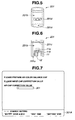
- FIG 5 is a view showing an appearance of an endoscope color-balance-adjustment tool used for the endoscope apparatus of the present embodiment
- FIG 6 is a section view of the endoscope color-balance-adjustment tool shown in FIG 5
- FIG 7 is a view showing an exemplary correction value input screen displayed on a monitor by the image processing apparatus of the present embodiment
- FIG 8 is a flow chart showing an exemplary processing to be performed in color balance adjustment
- FIG 12 is a view showing an exemplary image to be displayed on the monitor by the image processing apparatus of the present embodiment when performing the processing shown in FIG 11;
- FIG 13 is a view showing an exemplary character string inquiring of a user whether or not to perform color balance adjustment, which is displayed on the monitor by the image processing apparatus of the present embodiment;
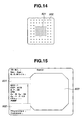
- FIG 14 is a view showing exemplary pixels to be sampled by the image processing apparatus of the present embodiment when calculating a correction value to perform color balance adjustment;
- FIG 15 is a view showing an exemplary standard image to be displayed on the monitor when observation is performed using the endoscope apparatus of the present embodiment;
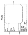
- FIG 16 is a view showing an exemplary high-definition image to be displayed on the monitor when observation is performed using the endoscope apparatus of the present embodiment.
- an endoscope apparatus 1 is configured by an endoscope 2 for picking up a subject image, a light source apparatus 3, a monitor 4 serving as a display apparatus for displaying a subject image picked up by the endoscope 2, and an image processing apparatus 5.
- the endoscope 2 includes inside thereof an image pickup unit 11, a light guide 12, and a storage unit 15 which is configured as a memory to/from which information can be freely written/read by means of a signal such as an electrical signal, and which has therein prewritten information such as type of the endoscope 2 and a value at factory shipment of a correction value used in color balance adjustment to be described below.
- the endoscope 2 also includes, on an outer covering surface thereof, an operation switch 13 and a connector 14 which is detachably connected to a connector 31 of the image processing apparatus 5 via a cable or the like not shown.
- the image pickup unit 11 which is provided in a distal end portion of the endoscope 2, includes an image pickup device such as CCD not shown (in FIG 1) and an object optical system such as a lens not shown (in FIG 1), picks up a subject image, and outputs the picked up subject image as an image signal.
- an image pickup device such as CCD not shown (in FIG 1)
- an object optical system such as a lens not shown (in FIG 1)
- the light guide 12 which is formed by quarts fibers or the like, is provided to be inserted inside the endoscope 2, with one end disposed in the distal end portion of the endoscope 2 and the other end disposed to be connected to the light source apparatus 3. With such a configuration, the light guide 12 leads lights radiated from the light source apparatus 3 to the distal end portion of the endoscope 2.
- the operation switch 13 when operated by a user, outputs as a signal an instruction to start and stop picking up a subject image to, for example, the image pickup unit 11 of the endoscope 2 via the image processing apparatus 5.
- the light source apparatus 3 includes therein a light source unit 21 comprised of a light source such as a xenon lamp, for radiating white light, an RGB filter 22, a fluorescent light observation filter 23, a condensing lens 24 for condensing irradiation light radiated from the light source unit 21 onto an incident end surface of the light guide 12, a filter control unit 25 for driving and controlling the RGB filter 22 and the fluorescent light observation filter 23, and a storage unit 27 which is configured as a memory to/from which information can be freely written/read by means of a signal such as an electrical signal, and which has therein prewritten information such as type and serial number of the light source apparatus 3.
- the light source apparatus 3 includes, on an outer covering surface thereof, an operation panel 26 and a connector 28 which is detachably connected to a connector 43 of the image processing apparatus 5 via a cable or the like not shown.
- the RGB filter 22 includes an R filter which transmits a light having a red wavelength band, a G filter which transmits a light having a green wavelength band, and a B filter which transmits a light having a blue wavelength band. These three kinds of filters included by the RGB filter 22 are formed to have correlation between wavelength bands and transmissivities as shown in FIG 2.
- the RGB filter 22 has a configuration such that, when the RGB filter 22 is disposed on an irradiation optical path of the light source unit 21 by the filter control unit 25, the R, G and B filters are inserted generally continuously on the irradiation optical path.
- the light source apparatus 3 when performing the normal observation, the light source apparatus 3 radiates normal observation irradiation light as first irradiation light, irradiating, in a frame sequential manner, a light having the red wavelength band, a light having the green wavelength band, and a light having the blue wavelength band.
- the fluorescent light observation filter 23 includes an Ex filter for transmitting a light including a predetermined wavelength band among the blue wavelength band, that excites fluorescent light from the subject; a ref1 filter for transmitting a light having a partial wavelength band among the green wavelength band; and a ref2 filter for transmitting a light having a partial wavelength band among the red wavelength band. These three kinds of filters included by the fluorescent light observation filter 23 are formed to have correlation between wavelength bands and transmissivities as shown in FIG 3.
- the fluorescent light observation filter 23 has a configuration such that, when the fluorescent light observation filter 23 is disposed on an irradiation optical path of the light source unit 21 by the filter control unit 25, the Ex, ref1 and ref2 filters are inserted generally continuously on the irradiation optical path.
- the light source apparatus 3 when performing the fluorescent light observation, the light source apparatus 3 radiates a fluorescent light observation irradiation light as a second irradiation light, which irradiates, in a frame sequential manner, an excitation light as a light having the predetermined wavelength band that excites fluorescent light from the subject, a ref1 light as a light having a partial wavelength band of the green wavelength band, and a ref2 light as a light having a partial wavelength band of the red wavelength band.
- the filter control unit 25 performs a control such as, for example, to dispose one of the RGB filter 22 and the fluorescent light observation filter 23 on the irradiation optical path of the light source unit 21 and thereafter drive to rotate the disposed filter.
- a control such as, for example, to dispose one of the RGB filter 22 and the fluorescent light observation filter 23 on the irradiation optical path of the light source unit 21 and thereafter drive to rotate the disposed filter.
- the filter control unit 25 performs such a control, the light source apparatus 3 radiates either the normal observation irradiation light or the fluorescent light observation irradiation light.
- the operation panel 26 includes a normal observation mode switch not shown for switching the irradiation light radiated from the light source apparatus 3 to the normal observation irradiation light, and a fluorescent light observation mode switch not shown for switching the irradiation light radiated from the light source apparatus 3 to the fluorescent light observation irradiation light.
- a signal including a control instruction to change the filter to be disposed on the irradiation optical path of the light source unit 21 is outputted from the operation panel 26 to the filter control unit 25.
- the signal including the control instruction is outputted also to the image processing apparatus 5 via the filter control unit 25. This allows the image processing apparatus 5 to detect whether the irradiation light radiated from the light source apparatus 3 is the normal observation irradiation light or the fluorescent light observation irradiation light.
- the light source apparatus 3 is not limited to radiating, as irradiation light, only the two kinds of irradiation lights: the normal observation irradiation light and the fluorescent light observation irradiation light. Besides the two kinds of irradiation lights, the light source apparatus 3 may radiate, for example, infrared observation irradiation light including a near infrared wavelength band, or narrow band observation irradiation light comprised of red, green and blue narrow band lights.
- the image processing apparatus 5 includes inside thereof a CCD drive unit 32 as a driving circuit for driving a CCD not shown (in FIG 1) provided in the image pickup unit 11, an image signal input unit 33, a color balance process unit 34, an image signal output unit 35, and an image processing apparatus control unit 42, as a control circuit comprised of a CPU and others, for controlling each of the endoscope 2, the light source apparatus 3, and the image processing apparatus 5.
- the image processing apparatus 5 includes, on an outer covering surface thereof, a connector 31 detachably connected to the connector 14 of the endoscope 2 via a cable or the like not shown, an operation panel 41, and a connector 43 detachably connected to the connector 28 of the light source apparatus 3 via a cable or the like not shown.
- the image signal input unit 33 is configured by circuits such as of an A/D converter not shown, and performs processings such as noise removal and A/D conversion on an image signal of a subject image outputted from the image pickup unit 11 of the endoscope 2, thereafter outputting an image signal after being subjected to the processings.
- the color balance process unit 34 When performing a color balance adjustment supporting each observation mode of the endoscope apparatus 1, the color balance process unit 34 performs, on the image signal outputted from the image signal input unit 33, brightness correction based on the color balance adjustment, and outputs an image signal subjected to the processing.
- an observation mode such as the normal light observation mode, which is an observation mode other than the fluorescent light observation mode
- the color balance process unit 34 of the image processing apparatus 5 is assumed to perform the white balance adjustment as one of color balance adjustments.
- the color balance process unit 34 of the image processing apparatus 5 In the fluorescent light observation mode, the color balance process unit 34 of the image processing apparatus 5 is assumed to perform a color balance adjustment different from the above-mentioned white balance adjustment.
- color balance adjustment is assumed to indicate both or either one of the color balance adjustment in the fluorescent light observation mode and the white balance adjustment in an observation mode other than the fluorescent light observation mode.
- the image signal output unit 35 includes circuits such as of an RGB multiplexer and D/A converter not shown.
- the image signal output unit 35 thus configured performs, on the image signal outputted from the color balance process unit 34, processings such as assigning signal components included in the image signal to R, G and B three color channels and D/A conversion, thereafter outputting an image signal assigned to these three color channels as a synchronized RGB image signal.
- the monitor 4 color-displays the subject image picked up by the image pickup unit 11, based on the RGB image signal outputted from the image signal output unit 35.
- the image signal output unit 35 includes, besides the above-mentioned circuits, an image generating circuit not shown to generate, for example, an image of a system menu screen of the endoscope apparatus 1, an image of a correction value input screen to be described later, and so on, based on a control signal from the image processing apparatus control unit 42.
- the operation panel 41 includes a color balance switch 101, as shown in FIG 4.
- a color balance switch 101 When the user operates the color balance switch 101, an instruction signal with a control instruction to perform color balance adjustment is outputted to the image processing apparatus control unit 42, in the endoscope apparatus 1.
- the operation panel 41 further includes a color balance setting incompletion display portion 102 to indicate that the color balance setting is incomplete, and a color balance setting completion display portion 103 to indicate that color balance setting is complete, as shown in FIG. 4.
- the color balance setting incompletion display portion 102 and the color balance setting completion display portion 103 as notifying portions indicate whether or not color balance adjustment has been performed, by, for example, reversing the lighting state of the LED according to setting state of color balance.
- the endoscope color-balance-adjustment tool 201 as a fluorescent light observation color balance chart, is configured as, for example, a tubular body with a generally cylindrical shape having an outer circumferential surface formed by a light-shielding member such as of metal or resin of macromolecule system, and a structure with one end closed.
- the endoscope color-balance-adjustment tool 201 has an aperture portion 201a with an inner diameter so as to allow insertion of the distal end portion of the endoscope 2, and an internal space 201b that communicates with the aperture portion 201a.
- the inner circumferential surface of the endoscope color-balance-adjustment tool 201 which forms the internal space 201b, is configured such that at least an end surface portion 201c has a fluorescent light generating portion formed by a fluorescent member such as a white paint, and further that the inner circumferential surface covers parts other than the aperture portion 201a.
- the fluorescent light generating portion provided on the inner circumferential surface of the endoscope color-balance-adjustment tool 201 is provided to be included in at least a part of an image of the inner circumferential surface picked up by the image pickup unit 11.
- a correction value display portion 201d showing a correction value WBCAF to be used in color balance adjustment described below.
- the correction value WBCAF is a value that is determined at the time of manufacture or factory shipment as a relative value when reference intensity of the fluorescent light emitted from the inner circumferential surface of the endoscope color-balance-adjustment tool is provided as "1.0".
- the correction value WBCAF is also a value shown as a correction value to correct variation in intensity of the fluorescent light emitted from the inner circumferential surface of the endoscope color-balance-adjustment tool 201.
- the state where the distal end portion of the endoscope 2 is inserted into the internal space 201b from the aperture portion 201a of the endoscope color-balance-adjustment tool 201 is as shown in FIG 6.
- an object optical system 11a of the image pickup unit 11 condenses the fluorescent light emitted from the fluorescent member on the inner circumferential surface of the endoscope color-balance-adjustment tool 201.
- the image pickup device 11b of the image pickup unit 11 provided at an image formation position of the object optical system, 11a picks up an image of the inner circumferential surface of the endoscope color-balance-adjustment tool 201 obtained by the object optical system 11a, thereafter converting the picked up image into an image signal to be outputted.
- the user connects parts that configure the main part of the endoscope apparatus 1, i.e., the endoscope 2, the light source apparatus 3, the monitor 4, and the image processing apparatus 5, and then turns on power of each of the parts of the endoscope apparatus 1 for activation.
- the CCD drive unit 32 drives the CCD not shown (in FIG 1) provided in the image pickup unit 11.
- the image processing apparatus control unit 42 reads pieces of type information of the endoscope 2 and the light source apparatus 3 that are written, respectively, in the storage unit 15 of the endoscope 2 and the storage unit 27 of the light source apparatus 3, to detect what kinds of observation modes the endoscope 2 and the light source apparatus 3 support.
- the user next turns on the fluorescent light observation mode switch of the light source apparatus 3 to cause fluorescent light observation irradiation light to be radiated from the light source apparatus 3.
- the user inserts the distal end portion of the endoscope 2 into the internal space 201b from the aperture portion 201a of the endoscope color-balance-adjustment tool 201, such that, for example, the distal end portion of the endoscope 2 is disposed at a position as shown in FIG 6 in the internal space 201b of the endoscope color-balance-adjustment tool 201.
- a mode change-over signal is outputted to the image processing apparatus control unit 42 via the filter control unit 25 and the connector 28.
- the image processing apparatus control unit 42 changes each part of the image processing apparatus 5 over to the fluorescent light observation mode, based on the mode change-over signal outputted from the operation panel 26.
- the image pickup unit 11 of the endoscope 2 picks up a subject image of the subject illuminated by the excitation light of the fluorescent light observation irradiation light, the subject image being comprised of an image of the fluorescent light emitted by the fluorescent member on the inner circumferential surface of the endoscope color-balance-adjustment tool 201, an image of reflection light of the ref1 light, and an image of reflection light of the ref2 light, and then outputs the picked up subject image as an image signal.
- the image signal outputted from the image pickup unit 11 is inputted to the image signal input unit 33 of the image processing apparatus 5.
- the each part of the image processing apparatus 5 performs color balance adjustment in the fluorescent light observation mode by a method described below.
- the initial state as a state before the below-described processings are performed, is assumed to be a state right before the color balance switch 101 is operated.
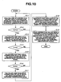
- the image processing apparatus control unit 42 When the color balance switch 101 is operated by the user and outputs an instruction signal to perform color balance adjustment in the fluorescent light observation mode (step S 1 of FIG 8), the image processing apparatus control unit 42 outputs a control signal for displaying, for example, the correction value input screen as shown in FIG 7 on the monitor 4, to the image signal output unit 35 based on the instruction signal.
- the image signal output unit 35 generates and displays a correction value input screen as shown in FIG 7 on the monitor 4 based on the control signal outputted from the image processing apparatus control unit 42 (step S2 of FIG 8).
- the image processing apparatus control unit 42 may control the image signal output unit 35 to display on the monitor 4, for example, a character string inquiring of the user whether or not to perform color balance adjustment in the fluorescent light observation mode, during the interval between when the processing shown in step S 1 of FIG 8 is performed and when the processing shown in step S2 of FIG 8 is performed.
- the image processing apparatus control unit 42 on detecting an instruction signal outputted from the color balance switch 101, controls the image signal output unit 35 to display on the monitor 4, for example, character strings reading "Should color balance setting be performed?", "Yes: Enter”, and "No: Esc".
- the image signal output unit 35 generates and displays a screen as shown in FIG 13 on the monitor 4, based on the control content of the image processing apparatus control unit 42.
- the image processing apparatus control unit 42 on detecting, for example, pushing down of an "Esc" key of a keyboard not shown connected to the image processing apparatus 5, brings the each part of the image processing apparatus 5 into the state right before the color balance switch 101 is operated. Also, the image processing apparatus control unit 42, on detecting, for example, pushing down of an "Enter” key of the keyboard not shown connected to the image processing apparatus 5, outputs to the image signal output unit 35, for example, a control signal to display the correction value input screen as shown in FIG 7 on the monitor 4. The image signal output unit 35 then generates and displays a correction value input screen as shown in FIG 7 on the monitor 4, based on the control signal outputted from the image processing apparatus control unit 42.
- the user uses, for example, a keyboard not shown connected to the image processing apparatus 5, or the like, to input to the correction value input portion 301 the correction value WBCAF which is displayed in the correction value display portion 201d of the endoscope color-balance-adjustment tool 201.
- the operation guiding portion 30 1 A On a part at a lower end of the monitor 4, there is displayed an operation guiding portion 30 1 A to show a list of operations the user can perform on the correction value input screen as shown in FIG 7.
- the correction value input portion 301 of the correction value input screen shown in FIG 7 is configured such that user operation of " ⁇ ” and " ⁇ ” keys of the keyboard not shown connected to the image processing apparatus 5 sequentially changes the displayed value. For example, when the user pushes down the " ⁇ ” and “ ⁇ ” keys of the keyboard not shown, correction values "0.5”, “0.6”, “0.7”, “0.8”, “0.9”, “1.0”, “-” “1.0”, “1.1”, “1.2”, “1.3”, “1.4” and “1.5” are sequentially displayed in the correction value input portion 301. Note that, in the initial state, "-” is assumed to be displayed in the correction value input portion 301. Furthermore, the values mentioned above as correction values are not limited to those selected by the " ⁇ ” and “ ⁇ ” keys of the keyboard not shown, but may be those directly inputted to the correction value input portion 301 by, for example, a numeric key of the keyboard not shown.
- the image processing apparatus control unit 42 judges whether or not the correction value WBCAF is inputted to the correction value input portion 301.
- the image processing apparatus control unit 42 judges that the correction value WBCAF is not inputted to the correction value input portion 301 (step S3 of FIG 8).
- the image processing apparatus control unit 42 then interrupts processing of the color balance adjustment in the fluorescent light observation mode, brings each of the endoscope 2, the light source apparatus 3, and the image processing apparatus 5 into the initial state, and maintains the initial state until the color balance switch 101 is reoperated by the user (step S1 of FIG 8).
- the image processing apparatus control unit 42 judges that the correction value WBCAF is inputted to the correction value input portion 301 (step S3 of FIG 8).
- correction value WBCAF may be associated to photometry mode and light adjustment level that are set by the image processing apparatus control unit 42 in performing the following processing.
- the image processing apparatus control unit 42 controls the image processing output unit 35 so as to turn the photometry mode and the light adjustment level as brightness of the entire screen into a predetermined state, based on the value of the selected correction value WBCAF.
- the image processing apparatus control unit 42 judges that intensity of the fluorescent light emitted from the inner circumferential surface of the endoscope color-balance-adjustment tool 201 is generally the same as the reference intensity of the fluorescent light, and controls the image processing output unit 35 to set the photometry mode to automatic and the light adjustment level value to "0".
- the image processing apparatus control unit 42 judges that intensity of the fluorescent light emitted from the inner circumferential surface of the endoscope color-balance-adjustment tool 201 is smaller than the reference intensity of the fluorescent light, and controls the image processing output unit 35 to set the photometry mode to automatic and the light adjustment level value to "+3". Note that the image processing apparatus control unit 42, when performing the above-mentioned control on the image processing output unit 35, invalidates, while temporarily holding, the photometry mode and light adjustment level value preset by the user. After having performed the above-mentioned control on the image processing output unit 35, the image processing apparatus control unit 42 again validates the photometry mode and light adjustment level value preset by the user, which are being held.
- the image processing apparatus control unit 42 calculates a mean value WBAF of brightness values for one screen of the image of the fluorescent light emitted by the fluorescent member on the inner circumferential surface of the endoscope color-balance-adjustment tool 201 (step S4 of FIG 8).
- the image processing apparatus control unit 42 further calculates a mean value WBR of brightness values for one screen of the image of the reflection light of the ref2 light on the inner circumferential surface of the endoscope color-balance-adjustment tool 201 (step S4 of FIG 8).
- the image processing apparatus control unit 42 calculates, using the following mathematical expressions (1) and (2), a correction value WBKAF for the fluorescent light image and a correction value WBKR for the image of the reflection light of the ref2 light, as values of coefficients to be used for color balance adjustment in the fluorescent light observation mode (step S5 of FIG 8).
- the image processing apparatus control unit 42 then outputs the correction value WBKAF for the fluorescent light image and the correction value WBKR for the image of the reflection light of the ref2 light, calculated, to the color balance process unit 34.
- the color balance process unit 34 performs brightness correction on the fluorescent light image and the image of the reflection light of the ref2 light, based on the correction value WBKAF for the fluorescent light image, the correction value WBKR for the image of the reflection light of the ref2 light, and the image signal inputted from the image signal input unit 33 (step S6 of FIG 8). After having performed the brightness correction based on the correction values WBKAF and WBKR, the color balance process unit 34 outputs the image signal after being subjected to the correction to the image signal output unit 35.
- the color balance process unit 34 is assumed to hold the correction values WBKAF and WBKR, and perform brightness correction on image signals inputted from the image signal input unit 33 based on those two correction values.
- the image signal output unit 35 assigns the image signal of the fluorescent light image to the G channel, the image signal of the image of the reflection light of the ref1 light to the R channel, and the image signal of the image of the reflection light of the ref2 light to the B channel, based on the image signal outputted from the color balance process unit 34, and thereafter outputs the image signals assigned to the three color channels as a synchronized RGB image signal (step S7 of FIG 8).
- the monitor 4 then color-displays the fluorescent light image picked up by the image pickup unit 11, based on the RGB image signal outputted from the image signal output unit 35.
- the correction value input screen into which a correction value is inputted, is not limited to the one shown in FIG 7, which is not displayed until the color balance switch 101 is operated.
- the correction value input screen may be such that, for example, the correction value input portion 301a is displayed as a part of a system menu screen of the endoscope apparatus 1 as shown in FIG 9. This allows the user to input the value displayed in the correction value display portion 201d of the endoscope color-balance-adjustment tool 201 in advance before performing color balance adjustment supporting each observation mode of the endoscope apparatus 1. As a result, the user can decentralize the load of works to be performed in color balance adjustment supporting each observation mode.
- a list of operations to be performed by the user using the keyboard not shown in the above-mentioned processings is displayed as a part of the correction value input screen as shown in FIG 7 on, for example, the operation guiding portion 301A. Therefore, the user can input the correction value WBCAF used in color balance adjustment in the fluorescent light observation mode without turning the eyes away from the monitor 4, while referring to an operation method displayed on the operation guiding portion 301A.
- the image processing apparatus 5 may be configured so as, for example, to sample the image signal of the image of the reflection light of the ref1 light outputted from the endoscope 2, in a manner to focusedly sample pixels in a part close to the center of an image based on the image signal, and thereafter calculate a correction value to perform color balance adjustment in the fluorescent light observation mode, based on brightness value of sampled predetermined number of pixels.
- the image processing apparatus control unit 42 of the image processing apparatus 5 first samples, for example, 80% of the predetermined number of pixels from a center portion 501 and 20% of the predetermined number of pixels from a peripheral portion 502 in the image based on the image signal outputted from the endoscope 2, as shown in FIG 14.
- the image processing apparatus control unit 42 detects respective brightness values of the sampled predetermined number of pixels, and holds the detected values. Further, the image processing apparatus control unit 42 specifies, of the held brightness values of the predetermined number of pixels, pixels with brightness values not less than 210 and pixels with brightness values not more than 15, and excludes the specified pixels from processing performed thereafter.
- the image processing apparatus control unit 42 calculates a mean value of the brightness values of the non-excluded remaining pixels, thereafter calculating, based on the mean value, a correction value to perform color balance adjustment in the fluorescent light observation mode.
- the image processing apparatus control unit 42 controls the image signal output unit 35 to display on the monitor 4 a character string indicating failure of color balance processing in the fluorescent light observation mode, without renewing the correction value to perform color balance adjustment in the fluorescent light observation mode.
- the endoscope apparatus 1 of the present embodiment can perform color balance adjustment that is based on the correction value WBCAF that is based on variation in fluorescent intensity of the fluorescent material provided on the inner circumferential surface of the endoscope color-balance-adjustment tool 201, among characteristic variations occurring with the endoscope color-balance-adjustment tool 201. Accordingly, the endoscope apparatus 1 of the present embodiment can obtain a good observation image.
- the aforementioned processings performed by the image processing apparatus 5 are described to be performed when the light source apparatus 3 has a function to emit only two kinds of irradiation lights: the normal observation irradiation light and the fluorescent light observation irradiation light, no limitation is placed thereon.
- the light source apparatus 3 further includes a function to emit, for example, infrared observation irradiation light supporting an infrared observation mode and narrow band observation irradiation light supporting a narrow band observation mode, in addition to the above-mentioned two kinds of irradiation lights, then the image processing apparatus 5 may perform the below-described processing in white balance adjustments respectively supporting the observation modes.
- the image processing apparatus control unit 42 of the image processing apparatus 5 reads, from the storage unit 15 of the endoscope 2, correction values to be used in respective white balance adjustments supporting the three kinds of observation modes associated to the connected light source apparatus 3, i.e., the normal observation mode, the narrow band observation mode, and the infrared observation mode. Thereafter, the image processing apparatus control unit 42 performs control to cause the color balance process unit 34 to hold values of the respective correction values in the three kinds of observation modes.
- the color balance process unit 34 holds the values of the respective correction values in the above-mentioned three kinds of observation modes, based on the control performed by the image processing apparatus control unit 42 (step S 11 of FIG 10).
- the image processing apparatus control unit 42 if detecting that in the storage unit 15 of the endoscope 2 there do not exist the respective correction values in the three kinds of observation modes, associated to the light source apparatus 3 connected, may define correction values held by the color balance process unit 34 as initial values.
- the image processing apparatus control unit 42 if detects that a time period T during which the instruction signal is continuously outputted by continuous pushing down of the color balance switch 101 is greater than a time period T1 (step S12 of FIG 10), obtains a mean value of brightness values for one screen in the normal observation mode, calculates a correction value for the white balance adjustment in the normal observation mode, and thereafter holds the calculated correction value (step S 13 of FIG 10).
- the image processing apparatus control unit 42 if detects that the time period T during which the instruction signal is continuously outputted by continuous pushing down of the color balance switch 101 is greater than a time period T2 (T1 ⁇ T2) (step S14 of FIG 10), obtains a mean value of brightness values for one screen in the narrow band observation mode, calculates a correction value for the white balance adjustment in the narrow band observation mode, thereafter holds the calculated correction value (step S15 of FIG 10).
- the image processing apparatus control unit 42 if detects that the time period T during which the instruction signal is continuously outputted by continuous pushing down of the color balance switch 101 is greater than a time period T3 (T2 ⁇ T3) (step S16 of FIG 10), obtains a mean value of brightness values for one screen in the infrared observation mode, calculates a correction value for the white balance adjustment in the infrared observation mode, and thereafter holds the calculated correction value (step S 17 of FIG 10).
- the image processing apparatus control unit 42 invalidates all the correction values obtained by performing the processings from steps S13 to S17 of FIG 10, and thereafter performs control to cause the color balance process unit 34 to hold the respective correction values in the three kinds of observation modes, originally held by the color balance process unit 34 (steps S 16 and S11 of FIG. 10).
- the image processing apparatus control unit 42 validates the correction values newly obtained in the above-mentioned processings from steps S 13 3 to S 17 of FIG 10. Thereafter, the image processing apparatus control unit 42 outputs, to the image signal output unit 35, a control signal having a content to cause the monitor 4 to display a character string indicating completion of white balance adjustments in all the three kinds of observation modes. Based on the control signal outputted from the image processing apparatus control unit 42, the image signal output unit 35 generates a character string indicating completion of white balance adjustments in all the three kinds of observation modes, which is displayed on the monitor 4 (step S 18 of FIG 10).
- the image processing apparatus control unit 42 performs control to cause the color balance process unit 34 to hold the respective correction values in the three kinds of observation modes, newly obtained in the processings from steps S 13 to S 17 of FIG 10. Based on the control performed by the image processing apparatus control unit 42, the color balance process unit 34 holds the correction values newly obtained in the processings from steps S 13 to S 17 of FIG 10, as respective correction values in the three kinds of observation modes (step S 19 of FIG 10).
- the image processing apparatus control unit 42 of the image processing apparatus 5 may perform control to invalidate the instruction signal outputted from the color balance switch 101.
- the user can prevent the endoscope apparatus 1, which includes the function to allow observation in, for example, the three kinds of observation modes, i.e., the normal observation mode, the infrared observation mode, and the narrow band observation mode, from being in a state where white balance adjustment is performed only in any one mode or where white balance adjustment is performed in each of the observation modes except any one mode.
- the image processing apparatus 5 performs control to cause the monitor 4 to display a character string indicating completion of white balance adjustments in all of the three kinds of observation modes.
- the user can perform observation in each of the three kinds of observation modes, having ensured that white balance adjustments have been performed in all of the three kinds of observation modes.
- the image processing apparatus 5 may perform the processings described below.
- the image processing apparatus control unit 42 of the image processing apparatus 5 starts reading a correction value associated to the connected light source apparatus 3, from the storage unit 15 of the endoscope 2 (step S21 of FIG 11).
- the image processing apparatus control unit 42 on having read the correction value (step S22 of FIG 11), judges whether or not data of the correction value has been normally read.
- the image processing apparatus control unit 42 also reads pieces of type information of the endoscope 2 and the light source apparatus 3 written in the storage unit 15 of the endoscope 2 and the storage unit 27 of the light source apparatus 3, respectively, and detects what kind of observation modes the endoscope 2 and the light source apparatus 3 support.
- the image processing apparatus control unit 42 calculates, in each of the observation modes supported by the endoscope 2 and the light source apparatus 3, a correction value to be used in the each color balance adjustment based on the data of the read correction value (step S24 of FIG 11), thereafter performing control to cause the color balance process unit 34 to hold the calculated correction value.
- the image processing apparatus control unit 42 then outputs, to the image signal output unit 35, a control signal to cause the monitor 4 to display a character string indicating completion of color balance adjustments in all of the observation modes supported by the endoscope 2 and the light source apparatus 3.
- the image signal output unit 35 Based on the control signal outputted from the image processing apparatus control unit 42, the image signal output unit 35 generates a character string indicating completion of color balance adjustment in each of the observation modes supported by the endoscope 2 and the light source apparatus 3, and displays the generated character string on the monitor 4 (step S25 of FIG 11).
- the method to indicate the completion of color balance adjustments in all of the observation modes supported by the endoscope 2 and the light source apparatus 3 is not limited to the afore-mentioned.
- the image processing apparatus control unit 42 may perform a control to turn the LED of the color balance setting incompletion display portion 102 of the operation panel 41 into a non-lighting state, and the LED of the color balance setting completion display portion 103 into a lighting state, to indicate the completion of color balance adjustments in all of the observation modes supported by the endoscope 2 and the light source apparatus 3.
- the image processing apparatus control unit 42 if judges that at least a part of the data of the correction value could not be normally read (step S23 of FIG 11), specifies an observation mode supporting the data of the correction value that could be normally read, and an observation mode supporting the data of the correction value that could not be normally read. The image processing apparatus control unit 42 then calculates a correction value to be used in color balance adjustment only for the observation mode supporting the data of the correction value that could be normally read among the data of the correction values (step S26 of FIG 11). The image processing apparatus control unit 42 then performs control to cause the color balance process unit 34 to hold the calculated correction value.
- the image processing apparatus control unit 42 outputs, to the image signal output unit 35, a control signal including a content to cause the monitor 4 to display a character string indicating incompletion of color balance adjustment in each of the observation modes supported by the endoscope 2 and the light source apparatus 3, and a content to prevent the monitor 4 from displaying a subject image picked up by the endoscope 2 in an observation mode in which the color balance adjustment is incomplete.
- the image signal output unit 35 Based on the control signal outputted from the image processing apparatus control unit 42, the image signal output unit 35 generates a character string reading, for example, "Please set color balance.” as shown in FIG 12, as a character string to indicate incompletion of white balance adjustment in the observation modes supported by the endoscope 2 and the light source apparatus 3, and displays the generated character string on the monitor 4 (step S27 of FIG 11).
- a character string reading for example, "Please set color balance.” as shown in FIG 12, as a character string to indicate incompletion of white balance adjustment in the observation modes supported by the endoscope 2 and the light source apparatus 3, and displays the generated character string on the monitor 4 (step S27 of FIG 11).
- the method to indicate the incompletion of color balance adjustment in the observation modes supported by the endoscope 2 and the light source apparatus 3 is not limited to the afore-mentioned.
- the image processing apparatus control unit 42 may perform a control to turn the LED of the color balance setting incompletion display portion 102 of the operation panel 41 into a lighting state, and the LED of the color balance setting completion display portion 103 into a non-lighting state, to indicate the incompletion of color balance adjustment in each of the observation modes supported by the endoscope 2 and the light source apparatus 3.
- the image signal output unit 35 further displays, based on the control signal outputted from the image processing apparatus control unit 42, another image such as, for example, a monochromatic image and a color bar image in, for example, an image display portion 302 as an area on the monitor 4 in which the image of the subject image picked up by the endoscope 2 is displayed, as shown in FIG 12 (step S28 ofFIG 11).
- another image such as, for example, a monochromatic image and a color bar image in, for example, an image display portion 302 as an area on the monitor 4 in which the image of the subject image picked up by the endoscope 2 is displayed, as shown in FIG 12 (step S28 ofFIG 11).
- the user in the observation using the endoscope apparatus 1, the user, for example, inputs a standard image as shown in FIG 15 to a recording apparatus such as a VTR and printer both not shown, and displays a high-definition image as shown in FIG 16 on the monitor 4.
- a recording screen by the standard image character strings or the like about the state of the endoscope apparatus 1 are displayed in notice display portions 601, 602 in such a manner to cover parts of the image display portion 603.
- character strings or the like about the state of the endoscope apparatus 1 are displayed in notice display portions 601a, 602a in such as manner to cover parts on an image display portion 603a which are generally the same as with the above-mentioned standard image.
- the character strings or the like displayed in the notice display portions 601, 602, 601a and 602a have a content to caution the user about, for example, malfunction of the light source apparatus 3. Therefore, after being displayed on the monitor 4, the character strings or the like displayed in the notice display portions 601, 602, 601 a and 602a may be deleted after passage of a predetermined time period.
- the user can clearly distinguish, among observation modes supported by the endoscope 2 and the light source apparatus 3, between those subjected and not subjected to color balance adjustment to be performed in each observation mode.
- the user is prevented from viewing a subject image with a color tone different from a desired color tone, thus allowing the user, for example, to proceed with observing the inside of the living body in a state of decreased chance of mistaking a lesion region for a normal region than in conventional cases.
Abstract
Description
- The present invention relates to an image processing apparatus, an endoscope apparatus, and a color balance adjusting method, and in particular, to an image processing apparatus, an endoscope apparatus, and a color balance adjusting method capable of correcting characteristic variation that occurs with a color balance adjustment tool when performing color balance adjustments.
- Endoscope apparatuses having an endoscope, a light source apparatus, and so on have conventionally been widely used in the medical field and the like. In particular, endoscope apparatuses used in the medical field are mainly used for the purpose of allowing a user to perform treatments such as inspection and observation of the inside of a living body. Generally known observations using the endoscope apparatus in the medical field include, for example, normal observation, in which white light is irradiated into a living body to pick up an image of the inside of the living body which is generally the same as in naked-eye observation, and additionally thereto, fluorescent light observation, in which excitation light including a specific wavelength band is irradiated into a living body to pick up an image of auto-fluorescent light emitted by biological tissues in the living body, the auto-fluorescent light image being observed to determine a normal region and a lesion region in the living body.
- In general, when performing a treatment such as inspection and observation with an endoscope, white balance adjustments respectively supporting observation modes of the endoscope apparatus are performed before the observation in order to adjust variation in color reproduction due to variations such as in sensitivity of a solid-state image pickup device in the endoscope, in optical characteristics of filter, lens or the like of a light source apparatus, and in chromatic aberration when the endoscope and the light source apparatus are connected to each other. For example, even in the case of performing treatments such as inspection and observation using endoscope apparatuses that are proposed in
Japanese unexamined patent publications Nos. 11-089789 10-201707 - The subjects used for the color balance adjustments including the above-mentioned white balance adjustment include, for example, one having a fluorescent member as a fluorescent light generating portion that emits fluorescent light by light. Of the above-mentioned subjects used for the color balance adjustments including the white balance adjustment, especially those having the fluorescent member are easily subjected to characteristic variations that occur in manufacture, such as, for example, variation in intensity of fluorescent light emitted by the fluorescent member.
- It is desirable that the color balance adjustments supporting the observation modes of the endoscope apparatus, which are performed before each observation with the endoscope apparatus, are performed taking into consideration characteristic variation of the subject used for the color balance adjustment, in addition to the above-mentioned characteristic variation at each part of the endoscope apparatus.
- However, in a fluorescent imaging apparatus of
Japanese unexamined patent publication No. 11-089789 Japanese unexamined patent publication No. 10-201707 - The present invention has been made in view of the above, and an object of the present invention is to provide an image processing apparatus, an endoscope apparatus, and a color balance adjusting method capable of obtaining a good observation image.
- An image processing apparatus of a first aspect of the present invention includes: an image signal input unit for inputting an image signal of a subject image picked up by an image pickup unit, the subject image including at least an image of a color balance adjustment tool; a control unit for calculating a value of coefficient to change brightness value of the image signal, based on a correction value to correct characteristic variation of the color balance adjustment tool, the correction value being shown in a correction value display portion included by the color balance adjustment tool, and a brightness value of the image of the color balance adjustment tool; and a color balance process unit for performing color balance adjustment by changing the brightness value of the image signal based on the coefl=icient value.
- An image processing apparatus of a second aspect of the present invention is the image processing apparatus of the first aspect, wherein the color balance adjustment tool has a tubular body provided with an aperture portion with a diameter to allow insertion of a distal end portion of an endoscope.
- An image processing apparatus of a third aspect of the present invention is the image processing apparatus of the first aspect, wherein the color balance adjustment tool includes a fluorescent light generating portion to emit fluorescent light, the fluorescent light generating portion being provided to be included in at least a part of the image of the color balance adjustment tool picked up by the image pickup unit.
- An image processing apparatus of a fourth aspect of the present invention is the image processing apparatus of the third aspect, wherein the characteristic variation is variation in intensity of the fluorescent light.
- An image processing apparatus of a fifth aspect of the present invention is the image processing apparatus of the first aspect, wherein the control unit performs control to cause a display apparatus to display a correction value input screen including a correction value input portion for inputting the correction value.
- An image processing apparatus of a sixth aspect of the present invention is the image processing apparatus of the fifth aspect, wherein the correction value input screen is a screen that is displayed including an operation guiding portion for showing a list of operations executable on the correction value input screen, and a message to urge a user to prepare necessary operations in inputting the correction value into the correction value input portion.
- An endoscope apparatus of a first aspect of the present invention includes: an endoscope including an image pickup unit for picking up a subject image including at least an image of a color balance adjustment tool and outputting the picked-up image as an image signal; and an image processing apparatus for performing color balance adjustment on the image signal, wherein the image processing apparatus calculates a value of coefficient to be used for the color balance adjustment, based on a brightness value of an image of the color balance adjustment tool picked up by the image pickup unit, and a correction value based on characteristic variation occurring with the color balance adjustment tool.
- An endoscope apparatus of a second aspect of the present invention is the endoscope apparatus of the first aspect, wherein the color balance adjustment tool has a tubular body provided with an aperture portion with a diameter to allow insertion of a distal end portion of the endoscope.
- An endoscope apparatus of a third aspect of the present invention is the endoscope apparatus of the first aspect, wherein the color balance adjustment tool includes a fluorescent light generating portion to emit fluorescent light, the fluorescent light generating portion being provided to be included in at least a part of the image of the color balance adjustment tool picked up by the image pickup unit.
- An endoscope apparatus of a fourth aspect of the present invention is the endoscope apparatus of the third aspect, wherein the characteristic variation is a variation in intensity of the fluorescent light.
- An endoscope apparatus of a fifth aspect of the present invention is the endoscope apparatus of the first aspect, wherein the control unit performs control to cause a display apparatus to display a correction value input screen including a correction value input portion for inputting the correction value.
- An endoscope apparatus of a sixth aspect of the present invention is the endoscope apparatus of the fifth aspect, wherein the correction value input screen is a screen that is displayed including an operation guiding portion for showing a list of operations executable on the correction value input screen, and a message to urge a user to prepare necessary operations in inputting the correction value into the correction value input portion.
- A color balance adjusting method of a first aspect of the present invention includes: an image signal input step for inputting an image signal of a subject image picked up by an image pickup unit, the subject image including at least an image of a color balance adjustment tool; a correction value input judgment step for judging whether or not there has been input of a correction value for correcting characteristic variation of the color balance adjustment tool, the correction value being shown in a correction value display portion included by the color balance adjustment tool; a brightness value calculation step for calculating, based on the image signal, a mean value of brightness values in an image including one wavelength band and a mean value of brightness values in an image including another wavelength band; and a coefficient calculation step for calculating a value of coefficient to be used for color balance adjustment, based on the correction value and each of the mean values calculated in the brightness value calculation step.
- A color balance adjusting method of a second aspect of the present invention is the color balance adjusting method of the first aspect, wherein the color balance adjustment tool includes a fluorescent light generating portion to emit fluorescent light, the fluorescent light generating portion being provided to be included in at least a part of the image of the color balance adjustment tool picked up by the image pickup unit.
- A color balance adjusting method of a third aspect of the present invention is the color balance adjusting method of the first aspect, wherein the characteristic variation is variation in intensity of the fluorescent light.
-
- FIG 1 is a block diagram showing an exemplary configuration of an endoscope apparatus of the present embodiment.
- FIG 2 is a view showing correlation between bands and transmissivities of an RGB filter included by a light source apparatus of the endoscope apparatus of the present embodiment.
- FIG 3 is a view showing correlation between bands and transmissivities of a fluorescent light observation filter included by the light source apparatus of the endoscope apparatus of the present embodiment.
- FIG 4 is a view showing an operation panel provided to an image processing apparatus configuring the endoscope apparatus of the present embodiment.
- FIG 5 is a view showing an appearance of an endoscope color-balance-adjustment tool used for the endoscope apparatus of the present embodiment.
- FIG 6 is a section view of the endoscope color-balance-adjustment tool shown in FIG S. '
- FIG 7 is a view showing an exemplary correction value input screen displayed on a monitor by the image processing apparatus of the present embodiment.
- FIG 8 is a flow chart showing an exemplary processing to be performed in color balance adjustment by the image processing apparatus of the present embodiment.
- FIG 9 is a view showing an exemplary menu screen displayed on the monitor, in the endoscope apparatus of the present embodiment.
- FIG 10 is a flow chart showing a processing to be performed in color balance adjustment by the image processing apparatus of the present embodiment, which is different from the processing shown in FIG 8.
- FIG 11 is a flow chart showing a processing performed in color balance adjustment by the image processing apparatus of the present embodiment, which is different from the processings shown in FIGS. 8 and 10.
- FIG 12 is a view showing an exemplary image to be displayed on the monitor by the image processing apparatus of the present embodiment when performing the processing shown in FIG 11.
- FIG 13 is a view showing an exemplary character string inquiring of a user whether or not to perform color balance adjustment, which is displayed on the monitor by the image processing apparatus of the present embodiment.
- FIG 14 is a view showing exemplary pixels to be sampled by the image processing apparatus of the present embodiment when calculating a correction value to perform color balance adjustment.
- FIG 15 is a view showing an exemplary standard image to be displayed on the monitor when observation is performed using the endoscope apparatus of the present embodiment.
- FIG 16 is a view showing an exemplary high-definition image to be displayed on the monitor when observation is performed using the endoscope apparatus of the present embodiment.
- An embodiment of the present invention is described with reference to the drawings, wherein: FIG 1 is a block diagram showing an exemplary configuration of an endoscope apparatus of the present embodiment; FIG 2 is a view showing correlation between bands and transmissivities of an RGB filter included by a light source apparatus of the endoscope apparatus of the present embodiment; FIG 3 is a view showing correlation between bands and transmissivities of a fluorescent light observation filter included by the light source apparatus of the endoscope apparatus of the present embodiment; FIG 4 is a view showing an operation panel provided to an image processing apparatus configuring the endoscope apparatus of the present embodiment; FIG 5 is a view showing an appearance of an endoscope color-balance-adjustment tool used for the endoscope apparatus of the present embodiment; FIG 6 is a section view of the endoscope color-balance-adjustment tool shown in FIG 5; FIG 7 is a view showing an exemplary correction value input screen displayed on a monitor by the image processing apparatus of the present embodiment; FIG 8 is a flow chart showing an exemplary processing to be performed in color balance adjustment by the image processing apparatus of the present embodiment; FIG 9 is a view showing an exemplary menu screen displayed on the monitor, in the endoscope apparatus of the present embodiment; FIG 10 is a flow chart showing a processing to be performed in color balance adjustment by the image processing apparatus of the present embodiment, which is different from the processing shown in FIG 8; FIG 11 is a flow chart showing a processing performed in color balance adjustment by the image processing apparatus of the present embodiment, which is different from the processings shown in FIGS. 8 and 10; FIG 12 is a view showing an exemplary image to be displayed on the monitor by the image processing apparatus of the present embodiment when performing the processing shown in FIG 11; FIG 13 is a view showing an exemplary character string inquiring of a user whether or not to perform color balance adjustment, which is displayed on the monitor by the image processing apparatus of the present embodiment; FIG 14 is a view showing exemplary pixels to be sampled by the image processing apparatus of the present embodiment when calculating a correction value to perform color balance adjustment; FIG 15 is a view showing an exemplary standard image to be displayed on the monitor when observation is performed using the endoscope apparatus of the present embodiment; and FIG 16 is a view showing an exemplary high-definition image to be displayed on the monitor when observation is performed using the endoscope apparatus of the present embodiment.
- As shown in FIG 1, main part of an
endoscope apparatus 1 is configured by anendoscope 2 for picking up a subject image, alight source apparatus 3, amonitor 4 serving as a display apparatus for displaying a subject image picked up by theendoscope 2, and animage processing apparatus 5. - The
endoscope 2 includes inside thereof animage pickup unit 11, alight guide 12, and astorage unit 15 which is configured as a memory to/from which information can be freely written/read by means of a signal such as an electrical signal, and which has therein prewritten information such as type of theendoscope 2 and a value at factory shipment of a correction value used in color balance adjustment to be described below. Theendoscope 2 also includes, on an outer covering surface thereof, anoperation switch 13 and aconnector 14 which is detachably connected to aconnector 31 of theimage processing apparatus 5 via a cable or the like not shown. - The
image pickup unit 11, which is provided in a distal end portion of theendoscope 2, includes an image pickup device such as CCD not shown (in FIG 1) and an object optical system such as a lens not shown (in FIG 1), picks up a subject image, and outputs the picked up subject image as an image signal. - The
light guide 12, which is formed by quarts fibers or the like, is provided to be inserted inside theendoscope 2, with one end disposed in the distal end portion of theendoscope 2 and the other end disposed to be connected to thelight source apparatus 3. With such a configuration, thelight guide 12 leads lights radiated from thelight source apparatus 3 to the distal end portion of theendoscope 2. - The operation switch 13, when operated by a user, outputs as a signal an instruction to start and stop picking up a subject image to, for example, the
image pickup unit 11 of theendoscope 2 via theimage processing apparatus 5. - The
light source apparatus 3 includes therein alight source unit 21 comprised of a light source such as a xenon lamp, for radiating white light, anRGB filter 22, a fluorescentlight observation filter 23, acondensing lens 24 for condensing irradiation light radiated from thelight source unit 21 onto an incident end surface of thelight guide 12, afilter control unit 25 for driving and controlling theRGB filter 22 and the fluorescentlight observation filter 23, and astorage unit 27 which is configured as a memory to/from which information can be freely written/read by means of a signal such as an electrical signal, and which has therein prewritten information such as type and serial number of thelight source apparatus 3. Thelight source apparatus 3 includes, on an outer covering surface thereof, anoperation panel 26 and aconnector 28 which is detachably connected to aconnector 43 of theimage processing apparatus 5 via a cable or the like not shown. - The
RGB filter 22 includes an R filter which transmits a light having a red wavelength band, a G filter which transmits a light having a green wavelength band, and a B filter which transmits a light having a blue wavelength band. These three kinds of filters included by theRGB filter 22 are formed to have correlation between wavelength bands and transmissivities as shown in FIG 2. TheRGB filter 22 has a configuration such that, when theRGB filter 22 is disposed on an irradiation optical path of thelight source unit 21 by thefilter control unit 25, the R, G and B filters are inserted generally continuously on the irradiation optical path. With theRGB filter 22 having the above-mentioned configuration, when performing the normal observation, thelight source apparatus 3 radiates normal observation irradiation light as first irradiation light, irradiating, in a frame sequential manner, a light having the red wavelength band, a light having the green wavelength band, and a light having the blue wavelength band. - The fluorescent
light observation filter 23 includes an Ex filter for transmitting a light including a predetermined wavelength band among the blue wavelength band, that excites fluorescent light from the subject; a ref1 filter for transmitting a light having a partial wavelength band among the green wavelength band; and a ref2 filter for transmitting a light having a partial wavelength band among the red wavelength band. These three kinds of filters included by the fluorescentlight observation filter 23 are formed to have correlation between wavelength bands and transmissivities as shown in FIG 3. The fluorescentlight observation filter 23 has a configuration such that, when the fluorescentlight observation filter 23 is disposed on an irradiation optical path of thelight source unit 21 by thefilter control unit 25, the Ex, ref1 and ref2 filters are inserted generally continuously on the irradiation optical path. With the fluorescentlight observation filter 23 having the above-mentioned configuration, when performing the fluorescent light observation, thelight source apparatus 3 radiates a fluorescent light observation irradiation light as a second irradiation light, which irradiates, in a frame sequential manner, an excitation light as a light having the predetermined wavelength band that excites fluorescent light from the subject, a ref1 light as a light having a partial wavelength band of the green wavelength band, and a ref2 light as a light having a partial wavelength band of the red wavelength band. - The
filter control unit 25 performs a control such as, for example, to dispose one of theRGB filter 22 and the fluorescentlight observation filter 23 on the irradiation optical path of thelight source unit 21 and thereafter drive to rotate the disposed filter. When thefilter control unit 25 performs such a control, thelight source apparatus 3 radiates either the normal observation irradiation light or the fluorescent light observation irradiation light. - The
operation panel 26 includes a normal observation mode switch not shown for switching the irradiation light radiated from thelight source apparatus 3 to the normal observation irradiation light, and a fluorescent light observation mode switch not shown for switching the irradiation light radiated from thelight source apparatus 3 to the fluorescent light observation irradiation light. When the user performs a change-over operation of these switches, a signal including a control instruction to change the filter to be disposed on the irradiation optical path of thelight source unit 21 is outputted from theoperation panel 26 to thefilter control unit 25. The signal including the control instruction is outputted also to theimage processing apparatus 5 via thefilter control unit 25. This allows theimage processing apparatus 5 to detect whether the irradiation light radiated from thelight source apparatus 3 is the normal observation irradiation light or the fluorescent light observation irradiation light. - Note that the
light source apparatus 3 is not limited to radiating, as irradiation light, only the two kinds of irradiation lights: the normal observation irradiation light and the fluorescent light observation irradiation light. Besides the two kinds of irradiation lights, thelight source apparatus 3 may radiate, for example, infrared observation irradiation light including a near infrared wavelength band, or narrow band observation irradiation light comprised of red, green and blue narrow band lights. - The
image processing apparatus 5 includes inside thereof aCCD drive unit 32 as a driving circuit for driving a CCD not shown (in FIG 1) provided in theimage pickup unit 11, an imagesignal input unit 33, a colorbalance process unit 34, an imagesignal output unit 35, and an image processingapparatus control unit 42, as a control circuit comprised of a CPU and others, for controlling each of theendoscope 2, thelight source apparatus 3, and theimage processing apparatus 5. Theimage processing apparatus 5 includes, on an outer covering surface thereof, aconnector 31 detachably connected to theconnector 14 of theendoscope 2 via a cable or the like not shown, anoperation panel 41, and aconnector 43 detachably connected to theconnector 28 of thelight source apparatus 3 via a cable or the like not shown. - The image
signal input unit 33 is configured by circuits such as of an A/D converter not shown, and performs processings such as noise removal and A/D conversion on an image signal of a subject image outputted from theimage pickup unit 11 of theendoscope 2, thereafter outputting an image signal after being subjected to the processings. - When performing a color balance adjustment supporting each observation mode of the
endoscope apparatus 1, the colorbalance process unit 34 performs, on the image signal outputted from the imagesignal input unit 33, brightness correction based on the color balance adjustment, and outputs an image signal subjected to the processing. Note that, in an observation mode such as the normal light observation mode, which is an observation mode other than the fluorescent light observation mode, the colorbalance process unit 34 of theimage processing apparatus 5 is assumed to perform the white balance adjustment as one of color balance adjustments. In the fluorescent light observation mode, the colorbalance process unit 34 of theimage processing apparatus 5 is assumed to perform a color balance adjustment different from the above-mentioned white balance adjustment. In other words, in the present embodiment, unless otherwise specified, color balance adjustment is assumed to indicate both or either one of the color balance adjustment in the fluorescent light observation mode and the white balance adjustment in an observation mode other than the fluorescent light observation mode. - The image
signal output unit 35 includes circuits such as of an RGB multiplexer and D/A converter not shown. The imagesignal output unit 35 thus configured performs, on the image signal outputted from the colorbalance process unit 34, processings such as assigning signal components included in the image signal to R, G and B three color channels and D/A conversion, thereafter outputting an image signal assigned to these three color channels as a synchronized RGB image signal. Then, themonitor 4 color-displays the subject image picked up by theimage pickup unit 11, based on the RGB image signal outputted from the imagesignal output unit 35. The imagesignal output unit 35 includes, besides the above-mentioned circuits, an image generating circuit not shown to generate, for example, an image of a system menu screen of theendoscope apparatus 1, an image of a correction value input screen to be described later, and so on, based on a control signal from the image processingapparatus control unit 42. - The
operation panel 41 includes acolor balance switch 101, as shown in FIG 4. When the user operates thecolor balance switch 101, an instruction signal with a control instruction to perform color balance adjustment is outputted to the image processingapparatus control unit 42, in theendoscope apparatus 1. Theoperation panel 41 further includes a color balance settingincompletion display portion 102 to indicate that the color balance setting is incomplete, and a color balance settingcompletion display portion 103 to indicate that color balance setting is complete, as shown in FIG. 4. - The color balance setting
incompletion display portion 102 and the color balance settingcompletion display portion 103 as notifying portions indicate whether or not color balance adjustment has been performed, by, for example, reversing the lighting state of the LED according to setting state of color balance. - As shown in FIG 5, the endoscope color-balance-
adjustment tool 201, as a fluorescent light observation color balance chart, is configured as, for example, a tubular body with a generally cylindrical shape having an outer circumferential surface formed by a light-shielding member such as of metal or resin of macromolecule system, and a structure with one end closed. The endoscope color-balance-adjustment tool 201 has anaperture portion 201a with an inner diameter so as to allow insertion of the distal end portion of theendoscope 2, and aninternal space 201b that communicates with theaperture portion 201a. The inner circumferential surface of the endoscope color-balance-adjustment tool 201, which forms theinternal space 201b, is configured such that at least anend surface portion 201c has a fluorescent light generating portion formed by a fluorescent member such as a white paint, and further that the inner circumferential surface covers parts other than theaperture portion 201a. In other words, the fluorescent light generating portion provided on the inner circumferential surface of the endoscope color-balance-adjustment tool 201 is provided to be included in at least a part of an image of the inner circumferential surface picked up by theimage pickup unit 11. - As shown in FIG 5, on an outer surface of the endoscope color-balance-
adjustment tool 201, there is provided a correctionvalue display portion 201d showing a correction value WBCAF to be used in color balance adjustment described below. Note that the correction value WBCAF is a value that is determined at the time of manufacture or factory shipment as a relative value when reference intensity of the fluorescent light emitted from the inner circumferential surface of the endoscope color-balance-adjustment tool is provided as "1.0". The correction value WBCAF is also a value shown as a correction value to correct variation in intensity of the fluorescent light emitted from the inner circumferential surface of the endoscope color-balance-adjustment tool 201. - Incidentally, the state where the distal end portion of the
endoscope 2 is inserted into theinternal space 201b from theaperture portion 201a of the endoscope color-balance-adjustment tool 201 is as shown in FIG 6. When excitation light is radiated from thelight guide 12 in such a state, an objectoptical system 11a of theimage pickup unit 11 condenses the fluorescent light emitted from the fluorescent member on the inner circumferential surface of the endoscope color-balance-adjustment tool 201. Then, theimage pickup device 11b of theimage pickup unit 11 provided at an image formation position of the object optical system, 11a picks up an image of the inner circumferential surface of the endoscope color-balance-adjustment tool 201 obtained by the objectoptical system 11a, thereafter converting the picked up image into an image signal to be outputted. - Next, workings of the
endoscope apparatus 1 of the present embodiment are described. - First, the user connects parts that configure the main part of the
endoscope apparatus 1, i.e., theendoscope 2, thelight source apparatus 3, themonitor 4, and theimage processing apparatus 5, and then turns on power of each of the parts of theendoscope apparatus 1 for activation. In such a state, theCCD drive unit 32 drives the CCD not shown (in FIG 1) provided in theimage pickup unit 11. Further in this state, the image processingapparatus control unit 42 reads pieces of type information of theendoscope 2 and thelight source apparatus 3 that are written, respectively, in thestorage unit 15 of theendoscope 2 and thestorage unit 27 of thelight source apparatus 3, to detect what kinds of observation modes theendoscope 2 and thelight source apparatus 3 support. - The user next turns on the fluorescent light observation mode switch of the
light source apparatus 3 to cause fluorescent light observation irradiation light to be radiated from thelight source apparatus 3. After having turned on the fluorescent light observation mode switch of thelight source apparatus 3, the user inserts the distal end portion of theendoscope 2 into theinternal space 201b from theaperture portion 201a of the endoscope color-balance-adjustment tool 201, such that, for example, the distal end portion of theendoscope 2 is disposed at a position as shown in FIG 6 in theinternal space 201b of the endoscope color-balance-adjustment tool 201. - When the fluorescent light observation mode switch is turned on through the
operation panel 26 of thelight source apparatus 3, a mode change-over signal is outputted to the image processingapparatus control unit 42 via thefilter control unit 25 and theconnector 28. The image processingapparatus control unit 42 changes each part of theimage processing apparatus 5 over to the fluorescent light observation mode, based on the mode change-over signal outputted from theoperation panel 26. - Thereafter, when the user performs the operation as mentioned above, the
image pickup unit 11 of theendoscope 2 picks up a subject image of the subject illuminated by the excitation light of the fluorescent light observation irradiation light, the subject image being comprised of an image of the fluorescent light emitted by the fluorescent member on the inner circumferential surface of the endoscope color-balance-adjustment tool 201, an image of reflection light of the ref1 light, and an image of reflection light of the ref2 light, and then outputs the picked up subject image as an image signal. The image signal outputted from theimage pickup unit 11 is inputted to the imagesignal input unit 33 of theimage processing apparatus 5. - In such a state, when, for example, the user operates the
color balance switch 101 of theoperation panel 41, the each part of theimage processing apparatus 5 performs color balance adjustment in the fluorescent light observation mode by a method described below. Note that the initial state, as a state before the below-described processings are performed, is assumed to be a state right before thecolor balance switch 101 is operated. - When the
color balance switch 101 is operated by the user and outputs an instruction signal to perform color balance adjustment in the fluorescent light observation mode (step S 1 of FIG 8), the image processingapparatus control unit 42 outputs a control signal for displaying, for example, the correction value input screen as shown in FIG 7 on themonitor 4, to the imagesignal output unit 35 based on the instruction signal. The imagesignal output unit 35 generates and displays a correction value input screen as shown in FIG 7 on themonitor 4 based on the control signal outputted from the image processing apparatus control unit 42 (step S2 of FIG 8). - Note that the image processing
apparatus control unit 42 may control the imagesignal output unit 35 to display on themonitor 4, for example, a character string inquiring of the user whether or not to perform color balance adjustment in the fluorescent light observation mode, during the interval between when the processing shown instep S 1 of FIG 8 is performed and when the processing shown in step S2 of FIG 8 is performed. - More specifically, the image processing
apparatus control unit 42, on detecting an instruction signal outputted from thecolor balance switch 101, controls the imagesignal output unit 35 to display on themonitor 4, for example, character strings reading "Should color balance setting be performed?", "Yes: Enter", and "No: Esc". The imagesignal output unit 35 generates and displays a screen as shown in FIG 13 on themonitor 4, based on the control content of the image processingapparatus control unit 42. - Thereafter, the image processing
apparatus control unit 42, on detecting, for example, pushing down of an "Esc" key of a keyboard not shown connected to theimage processing apparatus 5, brings the each part of theimage processing apparatus 5 into the state right before thecolor balance switch 101 is operated. Also, the image processingapparatus control unit 42, on detecting, for example, pushing down of an "Enter" key of the keyboard not shown connected to theimage processing apparatus 5, outputs to the imagesignal output unit 35, for example, a control signal to display the correction value input screen as shown in FIG 7 on themonitor 4. The imagesignal output unit 35 then generates and displays a correction value input screen as shown in FIG 7 on themonitor 4, based on the control signal outputted from the image processingapparatus control unit 42. - In the state where the correction value input screen as shown in FIG 7 is displayed on the
monitor 4, the user uses, for example, a keyboard not shown connected to theimage processing apparatus 5, or the like, to input to the correctionvalue input portion 301 the correction value WBCAF which is displayed in the correctionvalue display portion 201d of the endoscope color-balance-adjustment tool 201. On a part at a lower end of themonitor 4, there is displayed an operation guiding portion 30 1 A to show a list of operations the user can perform on the correction value input screen as shown in FIG 7. Note that, on the correction value input screen as shown in FIG 7, there are displayed character strings reading, for example, "Please prepare an AFI color balance cap." and "Please input a cap correction value." as messages to urge the user to make preparation for the operation about inputting the correction value WBCAF to the correctionvalue input portion 301, along with the correctionvalue input portion 301 and theoperation guiding portion 301A. - The correction
value input portion 301 of the correction value input screen shown in FIG 7 is configured such that user operation of "←" and "→" keys of the keyboard not shown connected to theimage processing apparatus 5 sequentially changes the displayed value. For example, when the user pushes down the "←" and "→" keys of the keyboard not shown, correction values "0.5", "0.6", "0.7", "0.8", "0.9", "1.0", "-" "1.0", "1.1", "1.2", "1.3", "1.4" and "1.5" are sequentially displayed in the correctionvalue input portion 301. Note that, in the initial state, "-" is assumed to be displayed in the correctionvalue input portion 301. Furthermore, the values mentioned above as correction values are not limited to those selected by the "←" and "→" keys of the keyboard not shown, but may be those directly inputted to the correctionvalue input portion 301 by, for example, a numeric key of the keyboard not shown. - Thereafter, the image processing
apparatus control unit 42 judges whether or not the correction value WBCAF is inputted to the correctionvalue input portion 301. - For example, if the "Esc" key of the keyboard not shown is pushed down, or if the "Enter" key of the keyboard not shown is pushed down in a state where the "-" is displayed in the correction
value input portion 301, the image processingapparatus control unit 42 judges that the correction value WBCAF is not inputted to the correction value input portion 301 (step S3 of FIG 8). The image processingapparatus control unit 42 then interrupts processing of the color balance adjustment in the fluorescent light observation mode, brings each of theendoscope 2, thelight source apparatus 3, and theimage processing apparatus 5 into the initial state, and maintains the initial state until thecolor balance switch 101 is reoperated by the user (step S1 of FIG 8). - If, for example, any correction value (except "-") is selected by the "←" and "→" keys of the keyboard not shown, followed by pushing down of the "Enter" key, then the image processing
apparatus control unit 42 judges that the correction value WBCAF is inputted to the correction value input portion 301 (step S3 of FIG 8). - Note that the correction value WBCAF may be associated to photometry mode and light adjustment level that are set by the image processing
apparatus control unit 42 in performing the following processing. In that case, the image processingapparatus control unit 42 controls the imageprocessing output unit 35 so as to turn the photometry mode and the light adjustment level as brightness of the entire screen into a predetermined state, based on the value of the selected correction value WBCAF. - More specifically, if, for example, "1.0" is selected as the correction value WBCAF, the image processing
apparatus control unit 42 judges that intensity of the fluorescent light emitted from the inner circumferential surface of the endoscope color-balance-adjustment tool 201 is generally the same as the reference intensity of the fluorescent light, and controls the imageprocessing output unit 35 to set the photometry mode to automatic and the light adjustment level value to "0". If, for example, "1.3" is selected as the correction value WBCAF, the image processingapparatus control unit 42 judges that intensity of the fluorescent light emitted from the inner circumferential surface of the endoscope color-balance-adjustment tool 201 is smaller than the reference intensity of the fluorescent light, and controls the imageprocessing output unit 35 to set the photometry mode to automatic and the light adjustment level value to "+3". Note that the image processingapparatus control unit 42, when performing the above-mentioned control on the imageprocessing output unit 35, invalidates, while temporarily holding, the photometry mode and light adjustment level value preset by the user. After having performed the above-mentioned control on the imageprocessing output unit 35, the image processingapparatus control unit 42 again validates the photometry mode and light adjustment level value preset by the user, which are being held. - Thereafter, the image processing
apparatus control unit 42 calculates a mean value WBAF of brightness values for one screen of the image of the fluorescent light emitted by the fluorescent member on the inner circumferential surface of the endoscope color-balance-adjustment tool 201 (step S4 of FIG 8). The image processingapparatus control unit 42 further calculates a mean value WBR of brightness values for one screen of the image of the reflection light of the ref2 light on the inner circumferential surface of the endoscope color-balance-adjustment tool 201 (step S4 of FIG 8). - Then, based on the mean value WBAF of the brightness values for one screen of the fluorescent light image, the mean value WBR of the brightness values for one screen of the reflection light image, and the correction value WBCAF inputted by the user, the image processing
apparatus control unit 42 calculates, using the following mathematical expressions (1) and (2), a correction value WBKAF for the fluorescent light image and a correction value WBKR for the image of the reflection light of the ref2 light, as values of coefficients to be used for color balance adjustment in the fluorescent light observation mode (step S5 of FIG 8).

- The image processing
apparatus control unit 42 then outputs the correction value WBKAF for the fluorescent light image and the correction value WBKR for the image of the reflection light of the ref2 light, calculated, to the colorbalance process unit 34. - The color
balance process unit 34 performs brightness correction on the fluorescent light image and the image of the reflection light of the ref2 light, based on the correction value WBKAF for the fluorescent light image, the correction value WBKR for the image of the reflection light of the ref2 light, and the image signal inputted from the image signal input unit 33 (step S6 of FIG 8). After having performed the brightness correction based on the correction values WBKAF and WBKR, the colorbalance process unit 34 outputs the image signal after being subjected to the correction to the imagesignal output unit 35. Note that, until a new correction value is outputted from the image processingapparatus control unit 42, the colorbalance process unit 34 is assumed to hold the correction values WBKAF and WBKR, and perform brightness correction on image signals inputted from the imagesignal input unit 33 based on those two correction values. - The image
signal output unit 35 assigns the image signal of the fluorescent light image to the G channel, the image signal of the image of the reflection light of the ref1 light to the R channel, and the image signal of the image of the reflection light of the ref2 light to the B channel, based on the image signal outputted from the colorbalance process unit 34, and thereafter outputs the image signals assigned to the three color channels as a synchronized RGB image signal (step S7 of FIG 8). - The
monitor 4 then color-displays the fluorescent light image picked up by theimage pickup unit 11, based on the RGB image signal outputted from the imagesignal output unit 35. - Note that the correction value input screen, into which a correction value is inputted, is not limited to the one shown in FIG 7, which is not displayed until the
color balance switch 101 is operated. Alternatively, the correction value input screen may be such that, for example, the correctionvalue input portion 301a is displayed as a part of a system menu screen of theendoscope apparatus 1 as shown in FIG 9. This allows the user to input the value displayed in the correctionvalue display portion 201d of the endoscope color-balance-adjustment tool 201 in advance before performing color balance adjustment supporting each observation mode of theendoscope apparatus 1. As a result, the user can decentralize the load of works to be performed in color balance adjustment supporting each observation mode. - In addition, a list of operations to be performed by the user using the keyboard not shown in the above-mentioned processings is displayed as a part of the correction value input screen as shown in FIG 7 on, for example, the
operation guiding portion 301A. Therefore, the user can input the correction value WBCAF used in color balance adjustment in the fluorescent light observation mode without turning the eyes away from themonitor 4, while referring to an operation method displayed on theoperation guiding portion 301A. - Furthermore, when performing color balance adjustment in the fluorescent light observation mode, the
image processing apparatus 5 may be configured so as, for example, to sample the image signal of the image of the reflection light of the ref1 light outputted from theendoscope 2, in a manner to focusedly sample pixels in a part close to the center of an image based on the image signal, and thereafter calculate a correction value to perform color balance adjustment in the fluorescent light observation mode, based on brightness value of sampled predetermined number of pixels. - More specifically, the image processing
apparatus control unit 42 of theimage processing apparatus 5 first samples, for example, 80% of the predetermined number of pixels from acenter portion 501 and 20% of the predetermined number of pixels from aperipheral portion 502 in the image based on the image signal outputted from theendoscope 2, as shown in FIG 14. The image processingapparatus control unit 42 then detects respective brightness values of the sampled predetermined number of pixels, and holds the detected values. Further, the image processingapparatus control unit 42 specifies, of the held brightness values of the predetermined number of pixels, pixels with brightness values not less than 210 and pixels with brightness values not more than 15, and excludes the specified pixels from processing performed thereafter. The image processingapparatus control unit 42 calculates a mean value of the brightness values of the non-excluded remaining pixels, thereafter calculating, based on the mean value, a correction value to perform color balance adjustment in the fluorescent light observation mode. - Note that, in the above-mentioned processing, if the number of the non-excluded remaining pixels, in the specifying and excluding of pixels with brightness values not less than 210 and not more than 15, is not more than 30% of the predetermined pixel number, the image processing
apparatus control unit 42 controls the imagesignal output unit 35 to display on the monitor 4 a character string indicating failure of color balance processing in the fluorescent light observation mode, without renewing the correction value to perform color balance adjustment in the fluorescent light observation mode. - As mentioned above, the
endoscope apparatus 1 of the present embodiment can perform color balance adjustment that is based on the correction value WBCAF that is based on variation in fluorescent intensity of the fluorescent material provided on the inner circumferential surface of the endoscope color-balance-adjustment tool 201, among characteristic variations occurring with the endoscope color-balance-adjustment tool 201. Accordingly, theendoscope apparatus 1 of the present embodiment can obtain a good observation image. - Note that, although the aforementioned processings performed by the
image processing apparatus 5 are described to be performed when thelight source apparatus 3 has a function to emit only two kinds of irradiation lights: the normal observation irradiation light and the fluorescent light observation irradiation light, no limitation is placed thereon. For example, if thelight source apparatus 3 further includes a function to emit, for example, infrared observation irradiation light supporting an infrared observation mode and narrow band observation irradiation light supporting a narrow band observation mode, in addition to the above-mentioned two kinds of irradiation lights, then theimage processing apparatus 5 may perform the below-described processing in white balance adjustments respectively supporting the observation modes. Note that the below-described processings for the each part of theimage processing apparatus 5 are assumed to be performed in the case where white balance adjustments respectively supporting the plurality of observation modes are performed in a sequential and continuous manner with respect to the plurality of observation modes, using the same endoscope color-balance-adjustment tool. - In the initial action after activation, the image processing
apparatus control unit 42 of theimage processing apparatus 5 reads, from thestorage unit 15 of theendoscope 2, correction values to be used in respective white balance adjustments supporting the three kinds of observation modes associated to the connectedlight source apparatus 3, i.e., the normal observation mode, the narrow band observation mode, and the infrared observation mode. Thereafter, the image processingapparatus control unit 42 performs control to cause the colorbalance process unit 34 to hold values of the respective correction values in the three kinds of observation modes. The colorbalance process unit 34 holds the values of the respective correction values in the above-mentioned three kinds of observation modes, based on the control performed by the image processing apparatus control unit 42 (step S 11 of FIG 10). Note that the image processingapparatus control unit 42, if detecting that in thestorage unit 15 of theendoscope 2 there do not exist the respective correction values in the three kinds of observation modes, associated to thelight source apparatus 3 connected, may define correction values held by the colorbalance process unit 34 as initial values. - Then, the image processing
apparatus control unit 42, if detects that a time period T during which the instruction signal is continuously outputted by continuous pushing down of thecolor balance switch 101 is greater than a time period T1 (step S12 of FIG 10), obtains a mean value of brightness values for one screen in the normal observation mode, calculates a correction value for the white balance adjustment in the normal observation mode, and thereafter holds the calculated correction value (step S 13 of FIG 10). - Further, the image processing
apparatus control unit 42, if detects that the time period T during which the instruction signal is continuously outputted by continuous pushing down of thecolor balance switch 101 is greater than a time period T2 (T1<T2) (step S14 of FIG 10), obtains a mean value of brightness values for one screen in the narrow band observation mode, calculates a correction value for the white balance adjustment in the narrow band observation mode, thereafter holds the calculated correction value (step S15 of FIG 10). - Still further, the image processing
apparatus control unit 42, if detects that the time period T during which the instruction signal is continuously outputted by continuous pushing down of thecolor balance switch 101 is greater than a time period T3 (T2 <T3) (step S16 of FIG 10), obtains a mean value of brightness values for one screen in the infrared observation mode, calculates a correction value for the white balance adjustment in the infrared observation mode, and thereafter holds the calculated correction value (step S 17 of FIG 10). - Note that, if the time period T during which the instruction signal is continuously outputted by continuous pushing down of the
color balance switch 101 is shorter than the time period T3, the image processingapparatus control unit 42 invalidates all the correction values obtained by performing the processings from steps S13 to S17 of FIG 10, and thereafter performs control to cause the colorbalance process unit 34 to hold the respective correction values in the three kinds of observation modes, originally held by the color balance process unit 34 (steps S 16 and S11 of FIG. 10). - Also, if the time period T during which the instruction signal is continuously outputted by continuous pushing down of the
color balance switch 101 is greater than the time period T3, the image processingapparatus control unit 42 validates the correction values newly obtained in the above-mentioned processings from steps S 13 3 to S 17 of FIG 10. Thereafter, the image processingapparatus control unit 42 outputs, to the imagesignal output unit 35, a control signal having a content to cause themonitor 4 to display a character string indicating completion of white balance adjustments in all the three kinds of observation modes. Based on the control signal outputted from the image processingapparatus control unit 42, the imagesignal output unit 35 generates a character string indicating completion of white balance adjustments in all the three kinds of observation modes, which is displayed on the monitor 4 (step S 18 of FIG 10). The image processingapparatus control unit 42 performs control to cause the colorbalance process unit 34 to hold the respective correction values in the three kinds of observation modes, newly obtained in the processings from steps S 13 to S 17 of FIG 10. Based on the control performed by the image processingapparatus control unit 42, the colorbalance process unit 34 holds the correction values newly obtained in the processings from steps S 13 to S 17 of FIG 10, as respective correction values in the three kinds of observation modes (step S 19 of FIG 10). - Note that, in the case that the above-mentioned white balance adjustments supporting the plurality of observation modes are performed as the procedure shown in FIG 10, if, for example, the
endoscope apparatus 1 is set as one of the narrow band observation mode and the infrared observation mode, the image processingapparatus control unit 42 of theimage processing apparatus 5 may perform control to invalidate the instruction signal outputted from thecolor balance switch 101. This makes it possible that, when performing white balance adjustments respectively supporting the three kinds of observation modes and the fluorescent light observation mode, using endoscope color-balance-adjustment tools each different for each observation mode, the user can perform the white balance adjustments supporting the observation modes without being confused with the endoscope color-balance-adjustment tools. - With the afore-mentioned processings being performed by the
image processing apparatus 5, the user can prevent theendoscope apparatus 1, which includes the function to allow observation in, for example, the three kinds of observation modes, i.e., the normal observation mode, the infrared observation mode, and the narrow band observation mode, from being in a state where white balance adjustment is performed only in any one mode or where white balance adjustment is performed in each of the observation modes except any one mode. Moreover, in the above-mentioned processings, theimage processing apparatus 5 performs control to cause themonitor 4 to display a character string indicating completion of white balance adjustments in all of the three kinds of observation modes. Thus, the user can perform observation in each of the three kinds of observation modes, having ensured that white balance adjustments have been performed in all of the three kinds of observation modes. - In addition, in the case of performing color balance adjustments respectively supporting the observation modes, using a correction value read from the
storage unit 15 of theendoscope 2, theimage processing apparatus 5 may perform the processings described below. - In the initial action after activation, the image processing
apparatus control unit 42 of theimage processing apparatus 5 starts reading a correction value associated to the connectedlight source apparatus 3, from thestorage unit 15 of the endoscope 2 (step S21 of FIG 11). The image processingapparatus control unit 42, on having read the correction value (step S22 of FIG 11), judges whether or not data of the correction value has been normally read. In this state, the image processingapparatus control unit 42 also reads pieces of type information of theendoscope 2 and thelight source apparatus 3 written in thestorage unit 15 of theendoscope 2 and thestorage unit 27 of thelight source apparatus 3, respectively, and detects what kind of observation modes theendoscope 2 and thelight source apparatus 3 support. - On judging that the data of the correction value has all been normally read (step S23 of FIG 11), the image processing
apparatus control unit 42 calculates, in each of the observation modes supported by theendoscope 2 and thelight source apparatus 3, a correction value to be used in the each color balance adjustment based on the data of the read correction value (step S24 of FIG 11), thereafter performing control to cause the colorbalance process unit 34 to hold the calculated correction value. The image processingapparatus control unit 42 then outputs, to the imagesignal output unit 35, a control signal to cause themonitor 4 to display a character string indicating completion of color balance adjustments in all of the observation modes supported by theendoscope 2 and thelight source apparatus 3. Based on the control signal outputted from the image processingapparatus control unit 42, the imagesignal output unit 35 generates a character string indicating completion of color balance adjustment in each of the observation modes supported by theendoscope 2 and thelight source apparatus 3, and displays the generated character string on the monitor 4 (step S25 of FIG 11). - Note that the method to indicate the completion of color balance adjustments in all of the observation modes supported by the
endoscope 2 and thelight source apparatus 3 is not limited to the afore-mentioned. For example, the image processingapparatus control unit 42 may perform a control to turn the LED of the color balance settingincompletion display portion 102 of theoperation panel 41 into a non-lighting state, and the LED of the color balance settingcompletion display portion 103 into a lighting state, to indicate the completion of color balance adjustments in all of the observation modes supported by theendoscope 2 and thelight source apparatus 3. - Also, the image processing
apparatus control unit 42, if judges that at least a part of the data of the correction value could not be normally read (step S23 of FIG 11), specifies an observation mode supporting the data of the correction value that could be normally read, and an observation mode supporting the data of the correction value that could not be normally read. The image processingapparatus control unit 42 then calculates a correction value to be used in color balance adjustment only for the observation mode supporting the data of the correction value that could be normally read among the data of the correction values (step S26 of FIG 11). The image processingapparatus control unit 42 then performs control to cause the colorbalance process unit 34 to hold the calculated correction value. Thereafter, the image processingapparatus control unit 42 outputs, to the imagesignal output unit 35, a control signal including a content to cause themonitor 4 to display a character string indicating incompletion of color balance adjustment in each of the observation modes supported by theendoscope 2 and thelight source apparatus 3, and a content to prevent themonitor 4 from displaying a subject image picked up by theendoscope 2 in an observation mode in which the color balance adjustment is incomplete. Based on the control signal outputted from the image processingapparatus control unit 42, the imagesignal output unit 35 generates a character string reading, for example, "Please set color balance." as shown in FIG 12, as a character string to indicate incompletion of white balance adjustment in the observation modes supported by theendoscope 2 and thelight source apparatus 3, and displays the generated character string on the monitor 4 (step S27 of FIG 11). - Note that the method to indicate the incompletion of color balance adjustment in the observation modes supported by the
endoscope 2 and thelight source apparatus 3 is not limited to the afore-mentioned. For example, the image processingapparatus control unit 42 may perform a control to turn the LED of the color balance settingincompletion display portion 102 of theoperation panel 41 into a lighting state, and the LED of the color balance settingcompletion display portion 103 into a non-lighting state, to indicate the incompletion of color balance adjustment in each of the observation modes supported by theendoscope 2 and thelight source apparatus 3. - The image
signal output unit 35 further displays, based on the control signal outputted from the image processingapparatus control unit 42, another image such as, for example, a monochromatic image and a color bar image in, for example, animage display portion 302 as an area on themonitor 4 in which the image of the subject image picked up by theendoscope 2 is displayed, as shown in FIG 12 (step S28 ofFIG 11). - Incidentally, in the observation using the
endoscope apparatus 1, the user, for example, inputs a standard image as shown in FIG 15 to a recording apparatus such as a VTR and printer both not shown, and displays a high-definition image as shown in FIG 16 on themonitor 4. On a recording screen by the standard image, character strings or the like about the state of theendoscope apparatus 1 are displayed innotice display portions image display portion 603. On an observation screen by the high-definition image, character strings or the like about the state of theendoscope apparatus 1 are displayed innotice display portions image display portion 603a which are generally the same as with the above-mentioned standard image. This allows the user to record the screen of the standard image, recognizing that theimage display portion 603 on the record screen of the standard image and theimage display portion 603a on the observation screen of the high-definition image are covered by the above-mentioned character strings or the like in generally the same manner. - Note that the character strings or the like displayed in the
notice display portions light source apparatus 3. Therefore, after being displayed on themonitor 4, the character strings or the like displayed in thenotice display portions - With the above-mentioned processings being performed in the
image processing apparatus 5, the user can clearly distinguish, among observation modes supported by theendoscope 2 and thelight source apparatus 3, between those subjected and not subjected to color balance adjustment to be performed in each observation mode. - In addition, with the above-mentioned processings being performed in the
image processing apparatus 5, the user is prevented from viewing a subject image with a color tone different from a desired color tone, thus allowing the user, for example, to proceed with observing the inside of the living body in a state of decreased chance of mistaking a lesion region for a normal region than in conventional cases. - Note that the present invention is not limited to the above-mentioned embodiment, and may of course be subject to various changes and applications without departing from the spirit of the invention.
- This application is filed claiming priority from
Japanese Patent Application No. 2005-149886 applied in Japan on May 23, 2005
Claims (15)
- An image processing apparatus, comprising:an image signal input unit for inputting an image signal of a subject image picked up by an image pickup unit, the subject image including at least an image of a color balance adjustment tool;a control unit for calculating a value of coefficient to change brightness value of the image signal, based on a correction value to correct characteristic variation of the color balance adjustment tool, the correction value being shown in a correction value display portion included by the color balance adjustment tool, and a brightness value of the image of the color balance adjustment tool; anda color balance process unit for performing color balance adjustment by changing the brightness value of the image signal based on the coefficient value.
- The image processing apparatus according to Claim 1, wherein the color balance adjustment tool has a tubular body provided with an aperture portion with a diameter to allow insertion of a distal end portion of an endoscope.
- The image processing apparatus according to Claim 1, wherein the color balance adjustment tool includes a fluorescent light generating portion to emit fluorescent light, the fluorescent light generating portion being provided to be included in at least a part of the image of the color balance adjustment tool picked up by the image pickup unit.
- The image processing apparatus according to Claim 3, wherein the characteristic variation is variation in intensity of the fluorescent light.
- The image processing apparatus according to Claim 1, wherein the control unit performs control to cause a display apparatus to display a correction value input screen including a correction value input portion for inputting the correction value.
- The image processing apparatus according to Claim 5, wherein the correction value input screen is a screen that is displayed including:an operation guiding portion for showing a list of operations executable on the correction value input screen, anda message to urge a user to prepare necessary operations in inputting the correction value into the correction value input portion.
- An endoscope apparatus comprising:an endoscope including an image pickup unit for picking up a subject image including at least an image of a color balance adjustment tool and outputting the picked-up image as an image signal; andan image processing apparatus for performing color balance adjustment on the image signal, whereinthe image processing apparatus calculates a value of coefficient to be used for the color balance adjustment, based on a brightness value of an image of the color balance adjustment tool picked up by the image pickup unit, and a correction value based on characteristic variation occurring with the color balance adjustment tool.
- The endoscope apparatus according to Claim 7, wherein the color balance adjustment tool has a tubular body provided with an aperture portion with a diameter to allow insertion of a distal end portion of the endoscope.
- The endoscope apparatus according to Claim 7, wherein the color balance adjustment tool includes a fluorescent light generating portion to emit fluorescent light, the fluorescent light generating portion being provided to be included in at least a part of the image of the color balance adjustment tool picked up by the image pickup unit.
- The endoscope apparatus according to Claim 9, wherein the characteristic variation is a variation in intensity of the fluorescent light.
- The endoscope apparatus according to Claim 7, wherein the control unit performs control to cause a display apparatus to display a correction value input screen including a correction value input portion for inputting the correction value.
- The endoscope apparatus according to Claim 11, wherein the correction value input screen is a screen that is displayed including
an operation guiding portion for showing a list of operations executable on the correction value input screen, and
a message to urge a user to prepare necessary operations in inputting the correction value into the correction value input portion. - A color balance adjusting method comprising:an image signal input step for inputting an image signal of a subject image picked up by an image pickup unit, the subject image including at least an image of a color balance adjustment tool; 'a correction value input judgment step for judging whether or not there has been input of a correction value for correcting characteristic variation of the color balance adjustment tool, the correction value being shown in a correction value display portion included by the color balance adjustment tool;a brightness value calculation step for calculating, based on the image signal, a mean value of brightness values in an image including one wavelength band and a mean value of brightness values in an image including another wavelength band; anda coefficient calculation step for calculating a value of coefficient to be used for color balance adjustment, based on the correction value and each of the mean values calculated in the brightness value calculation step.
- The color balance adjusting method according to Claim 13, wherein the color balance adjustment tool includes a fluorescent light generating portion to emit fluorescent light, the fluorescent light generating portion being provided to be included in at least a part of the image of the color balance adjustment tool picked up by the image pickup unit.
- The color balance adjusting method according to Claim 14, wherein the characteristic variation is variation in intensity of the fluorescent light.
Applications Claiming Priority (2)
| Application Number | Priority Date | Filing Date | Title |
|---|---|---|---|
| JP2005149886A JP5173120B2 (en) | 2005-05-23 | 2005-05-23 | Endoscope device |
| PCT/JP2006/303880 WO2006126318A1 (en) | 2005-05-23 | 2006-03-01 | Image processing device, endoscope device, and color balance adjusting method |
Publications (3)
| Publication Number | Publication Date |
|---|---|
| EP1884183A1 true EP1884183A1 (en) | 2008-02-06 |
| EP1884183A4 EP1884183A4 (en) | 2009-12-16 |
| EP1884183B1 EP1884183B1 (en) | 2015-12-30 |
Family
ID=37451750
Family Applications (1)
| Application Number | Title | Priority Date | Filing Date |
|---|---|---|---|
| EP06714997.1A Expired - Fee Related EP1884183B1 (en) | 2005-05-23 | 2006-03-01 | Endoscope device, and color balance adjusting method |
Country Status (8)
| Country | Link |
|---|---|
| US (1) | US8284245B2 (en) |
| EP (1) | EP1884183B1 (en) |
| JP (1) | JP5173120B2 (en) |
| KR (1) | KR100972242B1 (en) |
| CN (1) | CN101170939B (en) |
| AU (1) | AU2006250728B2 (en) |
| CA (1) | CA2608449C (en) |
| WO (1) | WO2006126318A1 (en) |
Cited By (4)
| Publication number | Priority date | Publication date | Assignee | Title |
|---|---|---|---|---|
| EP2090919A3 (en) * | 2008-02-15 | 2009-11-18 | Olympus Medical Systems Corporation | Signal processing system |
| EP2301413A1 (en) * | 2009-09-24 | 2011-03-30 | Fujifilm Corporation | Endoscope apparatus |
| EP2322075A1 (en) * | 2009-03-30 | 2011-05-18 | Olympus Medical Systems Corp. | Fluorescence observation device |
| CN102429627A (en) * | 2010-09-29 | 2012-05-02 | 富士胶片株式会社 | Endoscope system |
Families Citing this family (17)
| Publication number | Priority date | Publication date | Assignee | Title |
|---|---|---|---|---|
| JP4816563B2 (en) * | 2006-07-06 | 2011-11-16 | セイコーエプソン株式会社 | Image display system |
| JP2008110004A (en) * | 2006-10-30 | 2008-05-15 | Pentax Corp | Electronic endoscope apparatus |
| JP2009213673A (en) * | 2008-03-11 | 2009-09-24 | Fujinon Corp | Endoscope system and endoscope inspecting method |
| JP5424570B2 (en) * | 2008-04-10 | 2014-02-26 | Hoya株式会社 | Electronic endoscope processor, videoscope, and electronic endoscope apparatus |
| WO2011092901A1 (en) * | 2010-02-01 | 2011-08-04 | オリンパスメディカルシステムズ株式会社 | Image pickup unit for endoscope |
| CN102970916B (en) * | 2010-07-26 | 2015-04-22 | 奥林巴斯医疗株式会社 | Endoscope device and method for controlling endoscope device |
| JP5507376B2 (en) * | 2010-07-28 | 2014-05-28 | 三洋電機株式会社 | Imaging device |
| JP5244164B2 (en) * | 2010-10-18 | 2013-07-24 | 富士フイルム株式会社 | Endoscope device |
| JP5714875B2 (en) * | 2010-11-26 | 2015-05-07 | オリンパス株式会社 | Fluorescence endoscope device |
| CN102846301B (en) * | 2011-07-08 | 2014-07-02 | 上海交通大学 | Intelligent adjusting device of endoscope illumination |
| JP2015150138A (en) * | 2014-02-13 | 2015-08-24 | Hoya株式会社 | Endoscope system, image forming device, and mouthpiece |
| JP6234350B2 (en) * | 2014-09-30 | 2017-11-22 | 富士フイルム株式会社 | Endoscope system, processor device, operation method of endoscope system, and operation method of processor device |
| WO2017150071A1 (en) * | 2016-03-03 | 2017-09-08 | Hoya株式会社 | Correction data generation method and correction data generation device |
| CN110381806B (en) * | 2017-03-31 | 2021-12-10 | Hoya株式会社 | Electronic endoscope system |
| WO2019198576A1 (en) * | 2018-04-11 | 2019-10-17 | 富士フイルム株式会社 | Medical image processing device |
| JP7196016B2 (en) * | 2019-05-27 | 2022-12-26 | 富士フイルム株式会社 | Information processing device and its operating method, endoscope system and its operating method |
| CN110751611A (en) * | 2019-11-01 | 2020-02-04 | 深圳市博盛医疗科技有限公司 | Method for calibrating display colors of endoscope system and endoscope system |
Citations (4)
| Publication number | Priority date | Publication date | Assignee | Title |
|---|---|---|---|---|
| JPH0469615A (en) * | 1990-07-10 | 1992-03-04 | Olympus Optical Co Ltd | White balance adjuster for endoscope |
| JP2002336196A (en) * | 2001-05-16 | 2002-11-26 | Olympus Optical Co Ltd | Endoscopic equipment |
| EP1488732A1 (en) * | 2003-06-17 | 2004-12-22 | Olympus Corporation | Electronic endoscope device |
| EP1527729A1 (en) * | 2003-10-30 | 2005-05-04 | Olympus Corporation | Image processing apparatus |
Family Cites Families (29)
| Publication number | Priority date | Publication date | Assignee | Title |
|---|---|---|---|---|
| DE3883302T2 (en) * | 1987-06-04 | 1994-03-31 | Dainippon Screen Mfg | Device and method for stabilizing the amount of light from a fluorescent lamp. |
| JP2542089B2 (en) * | 1989-03-16 | 1996-10-09 | オリンパス光学工業株式会社 | Light source device for endoscope |
| US5504524A (en) * | 1993-10-15 | 1996-04-02 | Vlsi Vision Limited | Method and apparatus for controlling color balance of a video signal |
| GB9416406D0 (en) | 1994-08-13 | 1994-10-05 | Univ Of Huddersfield | Colour inspection system |
| FI107412B (en) | 1995-06-20 | 2001-07-31 | Teknillinen Korkeakoulu Graafi | A method and apparatus for maximizing the visual quality of an electronic image |
| JPH0910170A (en) * | 1995-06-29 | 1997-01-14 | Olympus Optical Co Ltd | Objective optical system of endoscope |
| DE19529366C2 (en) * | 1995-08-10 | 1998-06-04 | Wolf Gmbh Richard | Device for color correction in color images recorded by a video camera |
| US6307638B1 (en) | 1996-03-13 | 2001-10-23 | Canon Kabushiki Kaisha | Image processing apparatus and electronic equipment and their control method |
| US6293911B1 (en) | 1996-11-20 | 2001-09-25 | Olympus Optical Co., Ltd. | Fluorescent endoscope system enabling simultaneous normal light observation and fluorescence observation in infrared spectrum |
| JP3962122B2 (en) | 1996-11-20 | 2007-08-22 | オリンパス株式会社 | Endoscope device |
| JP3887060B2 (en) | 1997-04-09 | 2007-02-28 | ペンタックス株式会社 | Image correction information recording apparatus and image restoration processing apparatus for electronic still camera |
| US5876399A (en) * | 1997-05-28 | 1999-03-02 | Irvine Biomedical, Inc. | Catheter system and methods thereof |
| JPH1189789A (en) | 1997-09-24 | 1999-04-06 | Olympus Optical Co Ltd | Fluorescent image device |
| JP4624513B2 (en) * | 1999-01-19 | 2011-02-02 | オリンパス株式会社 | Microscope imaging device |
| JP4360724B2 (en) | 2000-01-11 | 2009-11-11 | Hoya株式会社 | Signal switching device for electronic endoscope |
| JP2001197485A (en) | 2000-01-11 | 2001-07-19 | Asahi Optical Co Ltd | Electronic endoscope system and electronic endoscope signal switching device |
| US6468204B2 (en) * | 2000-05-25 | 2002-10-22 | Fuji Photo Film Co., Ltd. | Fluorescent endoscope apparatus |
| JP4321697B2 (en) * | 2000-08-02 | 2009-08-26 | 富士フイルム株式会社 | Fluorescent image display method and apparatus |
| US6826424B1 (en) * | 2000-12-19 | 2004-11-30 | Haishan Zeng | Methods and apparatus for fluorescence and reflectance imaging and spectroscopy and for contemporaneous measurements of electromagnetic radiation with multiple measuring devices |
| US6989859B2 (en) * | 2000-12-22 | 2006-01-24 | Eastman Kodak Company | Camera having user interface ambient sensor viewer adaptation compensation and method |
| US7172553B2 (en) * | 2001-05-16 | 2007-02-06 | Olympus Corporation | Endoscope system using normal light and fluorescence |
| JP4172922B2 (en) | 2001-05-30 | 2008-10-29 | Hoya株式会社 | Electronic endoscope system and usage recording method of electronic endoscope system |
| JP2003000537A (en) * | 2001-06-27 | 2003-01-07 | Fuji Photo Film Co Ltd | Imaging method and apparatus for endoscope |
| JP2003334162A (en) * | 2002-03-14 | 2003-11-25 | Olympus Optical Co Ltd | Endoscopic image processor |
| JP4197879B2 (en) | 2002-03-15 | 2008-12-17 | オリンパス株式会社 | Endoscope device |
| JP4564239B2 (en) * | 2003-04-11 | 2010-10-20 | オリンパス株式会社 | Endoscope device |
| JP4315748B2 (en) | 2003-07-07 | 2009-08-19 | オリンパス株式会社 | Endoscope device |
| US8473035B2 (en) * | 2003-09-15 | 2013-06-25 | Beth Israel Deaconess Medical Center | Medical imaging systems |
| JP4504078B2 (en) * | 2004-04-26 | 2010-07-14 | オリンパス株式会社 | OPTICAL DEVICE HAVING AIR GAP REFERENCE POSITION ADJUSTMENT STRUCTURE FOR AIR GAP VARIABLE SPECTRAL TRANSMISSION VARIABLE ELEMENT AND AIR GAP REFERENCE POSITION ADJUSTMENT STRUCTURE FOR AIR GAP VARIABLE SPECTRAL TRANSMITTER VARIABLE ELEMENT |
-
2005
- 2005-05-23 JP JP2005149886A patent/JP5173120B2/en not_active Expired - Fee Related
-
2006
- 2006-03-01 EP EP06714997.1A patent/EP1884183B1/en not_active Expired - Fee Related
- 2006-03-01 WO PCT/JP2006/303880 patent/WO2006126318A1/en active Application Filing
- 2006-03-01 US US11/914,508 patent/US8284245B2/en active Active
- 2006-03-01 CA CA2608449A patent/CA2608449C/en not_active Expired - Fee Related
- 2006-03-01 AU AU2006250728A patent/AU2006250728B2/en not_active Ceased
- 2006-03-01 CN CN2006800150553A patent/CN101170939B/en active Active
- 2006-03-01 KR KR1020077022505A patent/KR100972242B1/en not_active IP Right Cessation
Patent Citations (4)
| Publication number | Priority date | Publication date | Assignee | Title |
|---|---|---|---|---|
| JPH0469615A (en) * | 1990-07-10 | 1992-03-04 | Olympus Optical Co Ltd | White balance adjuster for endoscope |
| JP2002336196A (en) * | 2001-05-16 | 2002-11-26 | Olympus Optical Co Ltd | Endoscopic equipment |
| EP1488732A1 (en) * | 2003-06-17 | 2004-12-22 | Olympus Corporation | Electronic endoscope device |
| EP1527729A1 (en) * | 2003-10-30 | 2005-05-04 | Olympus Corporation | Image processing apparatus |
Non-Patent Citations (1)
| Title |
|---|
| See also references of WO2006126318A1 * |
Cited By (8)
| Publication number | Priority date | Publication date | Assignee | Title |
|---|---|---|---|---|
| EP2090919A3 (en) * | 2008-02-15 | 2009-11-18 | Olympus Medical Systems Corporation | Signal processing system |
| US8284244B2 (en) | 2008-02-15 | 2012-10-09 | Olympus Medical Systems Corp. | Signal processing system |
| EP2322075A1 (en) * | 2009-03-30 | 2011-05-18 | Olympus Medical Systems Corp. | Fluorescence observation device |
| EP2322075A4 (en) * | 2009-03-30 | 2011-10-26 | Olympus Medical Systems Corp | Fluorescence observation device |
| EP2301413A1 (en) * | 2009-09-24 | 2011-03-30 | Fujifilm Corporation | Endoscope apparatus |
| US8624966B2 (en) | 2009-09-24 | 2014-01-07 | Fujifilm Corporation | Endoscope apparatus calibration with color correction table |
| CN102429627A (en) * | 2010-09-29 | 2012-05-02 | 富士胶片株式会社 | Endoscope system |
| CN102429627B (en) * | 2010-09-29 | 2014-10-29 | 富士胶片株式会社 | Endoscope system |
Also Published As
| Publication number | Publication date |
|---|---|
| CN101170939A (en) | 2008-04-30 |
| JP2006325672A (en) | 2006-12-07 |
| CA2608449C (en) | 2012-02-28 |
| KR100972242B1 (en) | 2010-07-23 |
| CN101170939B (en) | 2010-05-26 |
| EP1884183A4 (en) | 2009-12-16 |
| KR20070110899A (en) | 2007-11-20 |
| CA2608449A1 (en) | 2006-11-30 |
| EP1884183B1 (en) | 2015-12-30 |
| AU2006250728A1 (en) | 2006-11-30 |
| US8284245B2 (en) | 2012-10-09 |
| WO2006126318A1 (en) | 2006-11-30 |
| AU2006250728B2 (en) | 2010-04-22 |
| JP5173120B2 (en) | 2013-03-27 |
| US20090073261A1 (en) | 2009-03-19 |
Similar Documents
| Publication | Publication Date | Title |
|---|---|---|
| EP1884183B1 (en) | Endoscope device, and color balance adjusting method | |
| US8643710B2 (en) | Image pickup apparatus | |
| US7172553B2 (en) | Endoscope system using normal light and fluorescence | |
| EP2671498B1 (en) | Endoscope device | |
| JP2006198106A (en) | Electronic endoscope system | |
| US20070285771A1 (en) | Endoscope system | |
| EP2095758B1 (en) | Fluorescent endoscopic device and method of creating fluorescent endoscopic image | |
| CN104619236A (en) | Imaging device | |
| EP1089067B1 (en) | Apparatus for obtaining a fluorescence image | |
| JP3884265B2 (en) | Endoscope device | |
| EP3656283B1 (en) | Light source system, control device, and control method | |
| US20190350448A1 (en) | Endoscope system | |
| EP3238604B1 (en) | Processor device and control program for an endoscope | |
| JP2005204958A (en) | Autofluorescently observable electronic endoscope apparatus and system | |
| JP4526322B2 (en) | Endoscope device | |
| JP4611794B2 (en) | Fluorescence observation equipment | |
| JP4657003B2 (en) | Endoscope processor | |
| JP6301041B1 (en) | Processing apparatus, setting method, and program | |
| JP2006020788A (en) | Autofluorescently observable electronic endoscope apparatus and system | |
| JP2006006921A (en) | Electronic endoscope system | |
| JP2013252356A (en) | Fluorescence spectroscopic observation device and image processing method | |
| KR20180070133A (en) | Electronic endoscope system | |
| JP2006174952A (en) | White balance adjustment method and image processing apparatus |
Legal Events
| Date | Code | Title | Description |
|---|---|---|---|
| PUAI | Public reference made under article 153(3) epc to a published international application that has entered the european phase |
Free format text: ORIGINAL CODE: 0009012 |
|
| 17P | Request for examination filed |
Effective date: 20071114 |
|
| AK | Designated contracting states |
Kind code of ref document: A1 Designated state(s): DE FR GB |
|
| DAX | Request for extension of the european patent (deleted) | ||
| RBV | Designated contracting states (corrected) |
Designated state(s): DE FR GB |
|
| A4 | Supplementary search report drawn up and despatched |
Effective date: 20091118 |
|
| 17Q | First examination report despatched |
Effective date: 20100308 |
|
| GRAP | Despatch of communication of intention to grant a patent |
Free format text: ORIGINAL CODE: EPIDOSNIGR1 |
|
| INTG | Intention to grant announced |
Effective date: 20150720 |
|
| RAP1 | Party data changed (applicant data changed or rights of an application transferred) |
Owner name: OLYMPUS CORPORATION |
|
| GRAS | Grant fee paid |
Free format text: ORIGINAL CODE: EPIDOSNIGR3 |
|
| GRAA | (expected) grant |
Free format text: ORIGINAL CODE: 0009210 |
|
| STAA | Information on the status of an ep patent application or granted ep patent |
Free format text: STATUS: THE PATENT HAS BEEN GRANTED |
|
| AK | Designated contracting states |
Kind code of ref document: B1 Designated state(s): DE FR GB |
|
| REG | Reference to a national code |
Ref country code: GB Ref legal event code: FG4D |
|
| REG | Reference to a national code |
Ref country code: DE Ref legal event code: R096 Ref document number: 602006047594 Country of ref document: DE |
|
| RAP2 | Party data changed (patent owner data changed or rights of a patent transferred) |
Owner name: OLYMPUS CORPORATION |
|
| REG | Reference to a national code |
Ref country code: DE Ref legal event code: R097 Ref document number: 602006047594 Country of ref document: DE |
|
| RAP2 | Party data changed (patent owner data changed or rights of a patent transferred) |
Owner name: OLYMPUS CORPORATION |
|
| PLBE | No opposition filed within time limit |
Free format text: ORIGINAL CODE: 0009261 |
|
| STAA | Information on the status of an ep patent application or granted ep patent |
Free format text: STATUS: NO OPPOSITION FILED WITHIN TIME LIMIT |
|
| GBPC | Gb: european patent ceased through non-payment of renewal fee |
Effective date: 20160330 |
|
| 26N | No opposition filed |
Effective date: 20161003 |
|
| REG | Reference to a national code |
Ref country code: FR Ref legal event code: ST Effective date: 20161130 |
|
| PG25 | Lapsed in a contracting state [announced via postgrant information from national office to epo] |
Ref country code: GB Free format text: LAPSE BECAUSE OF NON-PAYMENT OF DUE FEES Effective date: 20160330 Ref country code: FR Free format text: LAPSE BECAUSE OF NON-PAYMENT OF DUE FEES Effective date: 20160331 |
|
| PGFP | Annual fee paid to national office [announced via postgrant information from national office to epo] |
Ref country code: DE Payment date: 20190321 Year of fee payment: 14 |
|
| REG | Reference to a national code |
Ref country code: DE Ref legal event code: R119 Ref document number: 602006047594 Country of ref document: DE |
|
| PG25 | Lapsed in a contracting state [announced via postgrant information from national office to epo] |
Ref country code: DE Free format text: LAPSE BECAUSE OF NON-PAYMENT OF DUE FEES Effective date: 20201001 |