EP1890133A2 - Method for analysing the sample of a liquid - Google Patents
Method for analysing the sample of a liquid Download PDFInfo
- Publication number
- EP1890133A2 EP1890133A2 EP07013307A EP07013307A EP1890133A2 EP 1890133 A2 EP1890133 A2 EP 1890133A2 EP 07013307 A EP07013307 A EP 07013307A EP 07013307 A EP07013307 A EP 07013307A EP 1890133 A2 EP1890133 A2 EP 1890133A2
- Authority
- EP
- European Patent Office
- Prior art keywords
- liquid
- measurement
- sample
- measuring
- photometric
- Prior art date
- Legal status (The legal status is an assumption and is not a legal conclusion. Google has not performed a legal analysis and makes no representation as to the accuracy of the status listed.)
- Granted
Links
Images


Classifications
-
- G—PHYSICS
- G01—MEASURING; TESTING
- G01N—INVESTIGATING OR ANALYSING MATERIALS BY DETERMINING THEIR CHEMICAL OR PHYSICAL PROPERTIES
- G01N21/00—Investigating or analysing materials by the use of optical means, i.e. using sub-millimetre waves, infrared, visible or ultraviolet light
- G01N21/84—Systems specially adapted for particular applications
- G01N21/8483—Investigating reagent band
Definitions
- the invention relates to a method for examining a sample of a liquid, in particular a sample of a body fluid.
- Samples of liquids are analyzed for different analysis purposes in different applications, for example to determine an analyte in the liquid.
- the fluids that are analyzed in this way include, in particular, body fluids such as urine and blood.
- test systems are used in which a detection zone is formed, i. H. an area of the test system in which the sample of liquid is introduced to then determine the analyte.
- test systems are known on the one hand as so-called test strips, which in one embodiment use a composite of several nonwoven material sections, and on the other hand as test systems with a spatial cavity structure.
- test system is in the form of a test strip in the document US 6,707,554 B1 described.
- the sample of the liquid in the detection zone is examined photometrically, ie light is irradiated onto the sample of the liquid, and then one or more spectroscopic measured variables are detected with the aid of a detector device, in particular the absorption behavior, the transmission behavior or the remission behavior of the sample the liquid in the detection zone.
- one or more analytes in the sample of the liquid can then be determined.
- the detection zone and the measuring zone are formed separately in the known test system, but have a spatial proximity to each other.
- the detection zone with detection light and the measuring zone with measuring light from different light sources are irradiated spatially resolved, d. H.
- the measuring light for the photometric measurement of the measuring zone essentially only reaches the area of the measuring zone and not into the area of the detection zone and vice versa.
- This spatially resolved irradiation is achieved by means of an optical imaging system, which may for example be one or more optical lenses, which is arranged between the test system and the light sources.
- the optical imaging system complicates the measurement setup and also increases the space required for the measurement setup.
- the object of the invention is to provide an improved method for examining a sample of a liquid, in particular a sample of a body fluid, which can be carried out with reduced effort. While maintaining a high sensitivity of the investigation material and costs should be saved compared to the prior art.
- this object is achieved by a method for examining a sample of a liquid, in particular a sample of a body fluid, in which, as a result of loading a test system with a sample of a liquid, the sample of the liquid reaches a measuring zone of the test system and propagates in the measuring zone and in which a filling measure characterizing the propagation of the sample of the liquid in the measuring zone is determined by using a photometric filling measurement of the sample of the liquid in the measuring zone, wherein the photometric filling measurement is carried out with measuring light of a measuring light wavelength irradiated onto the sample of the liquid in the measuring zone, for which the liquid has a substantially constant optical behavior upon variation of at least one liquid parameter, which is selected by at least one spectroscopic measurement variable selected from a group of spectroscopic measurement variables n, namely absorption, transmission, remission and fluorescence, and wherein the at least one fluid parameter characterizes at least one of the following properties: chemical composition, concentration and activity of one or more compounds contained
- Wavelengths in which the behavior of a spectroscopic measured variable for a liquid to be examined is essentially independent of the variation of at least one liquid parameter are assigned to a characteristic point in the wavelength spectrum of the spectroscopic measurement variable for the liquid, which is also referred to as isobestic or isosbestic point.
- the measuring light wavelength used for the photometric filling measurement of the measuring zone can also be referred to as the iso (s) best measuring light wavelength.
- the proposed method makes it possible to dispense with expensive and costly optical imaging systems in the measuring arrangement for examining the test system, since a spatially resolved examination of detection zone and measuring zone is no longer necessary. There is no need for a clean spatial separation of the irradiation areas for the measuring light for the photometric examination of the measuring zone on the one hand and the detection light, namely the light for the investigation of the detection zone, on the other hand required. Exactly this is hardly realizable without the optical imaging system. Nevertheless, a reliable determination of the degree of filling of the measuring zone is ensured by means of the proposed method due to the specific choice of the measuring light wavelength for the measuring light of the photometric examination of the measuring zone.
- the filling of the measuring zone is preferably carried out by a substantially flat distribution of the sample of the liquid in the measuring zone.
- the information about the filling size is an essential parameter for the exact evaluation of the measurement results, especially if the thickness of the sample zone negligible Area is.
- using information about the fill size it may be used to gain insight into which volume of the sample of liquid has been analyzed. This is of particular importance in particular when the measuring zone and the detection zone are formed at least partially overlapping in the test system. It can also be provided that the measuring zone and the detection zone are identical.
- the proposed method provides a way to determine the degree of filling of a region with the sample of the liquid, regardless of the purposes for which this information is then used.
- the proposed method is particularly suitable for examining liquid samples in test systems where rapid reaction chemistry is used.
- the filling of the measuring zone and a detection reaction take place here essentially in parallel, which is why an independent fill level control, which is not influenced by the analyte concentration, is of particular importance.
- the chemical composition of a compound contained in the liquid can change in different ways. For example, in one embodiment, a conversion of a starting product gradually into a reaction product take place, so that the reaction product is increasingly present in the sample of the liquid. For example, in conjunction with the parameter concentration, the behavior for the remission of an aqueous glucose solution changes only insignificantly for different glucose concentrations for light of specific wavelengths.
- a chemical or a biochemical activity tested This may be, for example, an enzymatic activity, in particular in the field of biochemistry, which is a measure of a reaction-accelerating effect of a catalyst or an enzyme.
- a biological activity can be checked as a characteristic, which is commonly understood in general the effectiveness of a substance in the biological system, for example as an enzyme.
- a preferred development of the invention provides that the measuring zone is wetted by the liquid during spreading of the sample of the liquid in the measuring zone.
- Wetting is generally understood to mean the formation of an interface between the liquid and a solid material.
- the measuring zone is moistened by the liquid when the sample of liquid in the measuring zone spreads out. Wetting on the one hand and moistening on the other hand can occur exclusively or combined when filling the measuring zone with the sample of the liquid. If the material in which the measuring zone is formed, for example a material that does not absorb the liquid, wetting will lead to filling of the measuring zone.
- a section with an absorbent material is also formed in the measuring zone, it may come to the so-called humidification of this material when filling the measuring zone, which is occasionally considered as a special case of wetting, as this is usually wetted inner surfaces of a material ,
- the photometric filling measurement is carried out time-resolved.
- a development of the invention can provide that a time course of the at least one spectroscopic measured variable is measured.
- a preferred embodiment of the invention provides that a time course for the Greepsus is determined.
- the filling dimension is determined from measured values for the at least one spectroscopic measured variable which are measured at a user-definable time after the irradiation of the measuring light with the measuring light wavelength.
- a preferred embodiment of the invention provides that a point in time is selected as the user-defined time in which the at least one spectroscopic measured variable assumes an extreme value.
- a suitable extreme value is, for example, a minimum of the spectroscopic measured variable over time after irradiation of the measuring light. But even a maximum of the curve can be used.
- a system is used as the test system which implements at least one test system type selected from the following group of test system types: test strip, test field, test system with a cavity structure for receiving the sample of the liquid and microfluidic test system.
- the method can be used for test systems in a variety of test system types, for example on the basis of woven nets, fleece, paper, film, microstructures or the like. These include in particular test strips, which are usually designed as strips with a composite of nonwoven materials.
- Other test systems have a cavity structure in a base body made, for example, as an injection molding component. In the cavity structure different zones are formed, which are useful for the investigation of the sample of the liquid.
- these include, for example, a reagent zone in which one or more reagents are arranged, which in particular can react with an analyte encompassed by the liquid, or a reaction zone in which the reaction between the one or more reagents and the analyte of the liquid takes place.
- a reagent zone in which one or more reagents are arranged, which in particular can react with an analyte encompassed by the liquid
- a reaction zone in which the reaction between the one or more reagents and the analyte of the liquid takes place.
- One or more zones may be spatially overlapping, both in the test strips and in the test systems with the cavity structure. Microfluidic test systems have the particular advantage that the required volume of the sample of the liquid can be further minimized.
- an analysis measurement is carried out for analyzing the sample of the liquid.
- an analyte in the sample of the liquid is preferably determined.
- an analysis measurement is provided in which the sample of the liquid is analyzed.
- the analysis may be, for example, to determine an analyte in the sample of the liquid.
- the detection of other physical or chemical properties of the sample of the liquid in the test system may also be provided as an alternative or in addition to the determination of the analyte. For this purpose, different measuring methods can be used.
- a development of the invention may provide that the analysis measurement comprises a measurement selected from the following group of measurements: electrochemical measurement and photometric measurement.
- a preferred embodiment of the invention provides that the analysis measurement is started in dependence on a Gree-data signal, which is derived from an electronically evaluable information on the determined Gree.
- the Gree data signal can be used, for example, to display information about the degree of filling of the measuring zone on a screen of the measuring arrangement for information of the user.
- the use of the Gree-data signal is also possible for complementary measurement data.
- the analysis measurement is carried out according to at least one measurement method design selected from the following group of measurement process configurations: at least partially overlapping in time with the photometric fill measurement, starting before the photometric fill measurement, starting after the photometric fill measurement, ending before the photometric filling measurement and ending after the photometric filling measurement.
- the photometric fill measurement and the analysis measurement can be carried out in any temporal relation to one another depending on the specific measurement arrangement and a selected measurement regime.
- a multiple repetition of the photometric filling measurement can also be provided, for example before, during and after the analysis measurement. As a result, the degree of filling of the measuring zone can be continuously monitored.
- An advantageous embodiment of the invention provides that the analysis measurement is carried out in a detection zone of the test system which is at a distance from the measuring zone.
- the detection zone is preferably downstream of the measuring zone.
- the information about the Artery is used to start the analysis measurement.
- the information about the Artiller in the measuring zone can be used as an indicator for filling the detection zone.
- the measuring zone and the detection zone may also be formed at least partially spatially overlapping or even identical.
- Fig. 1 shows a schematic representation of a measuring arrangement for examining a sample of a liquid in a test system.
- a measuring zone 2 and a detection zone 3 connected downstream of the measuring zone 2 are formed in a test field level 1.
- the test field plane 1 opposite a photometric measuring device 4 is arranged, which has a first light source 5 and a second light source 6 and the two light sources 5, 6 associated detector 7.
- the detector 7 is preferably formed by means of a photodiode.
- a region 8 between the test field plane 1 and the photometric measuring device 4 is free of imaging optical systems such as lenses.
- measuring light 5a is generated with a measuring light wavelength and irradiated to the test field level 1 so that at least the measuring zone 2 is detected.
- Detection light 6a having a detection light wavelength is also generated by the second light source 6, which is likewise embodied as a monochromatic light-emitting diode, and likewise radiated onto the test field plane 1, so that at least the detection zone 3 is detected by it.
- simple aperture (not shown), such as pinhole can be used.
- color filters may be connected upstream of the detector 7, which are adapted to the measurement light wavelength and the detection light wavelength.
- particularly narrow-band color filters are suitable.
- the detector 7 With the detector 7, light can be detected, which is reflected by the sample of liquid in the measuring zone 2 and the detection zone 3.
- the person skilled in the art can select light components which can be evaluated in a suitable manner for the information to be determined from the examinations.
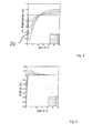
- FIG. 2 shows a graphic representation of a time course of the remission at a measuring light wavelength of 490 nm for blood samples with different glucose concentrations between 25 mg / dl and 600 mg / dl.
- Fig. 3 shows a graph of a time course of the remission at a wavelength of 650 nm for blood samples with different glucose concentrations.
- the glucose concentration was varied between 25mg / dl and 600mg / dl comparable to the studies shown in FIG. It is readily apparent that at the wavelength of 650nm, the extent of remission for the blood samples with different glucose concentrations will be different, even if a similar time course is measured.
- Photometric measurements at a measuring light wavelength of about 490 nm, as shown in FIG. 2 for blood samples with different glucose concentrations, can now be used to determine the extent to which the measuring zone 2 is filled with the blood sample to be examined by wetting and / or moistening. Subsequently, the evaluation used for determining a Greins for filling the measuring zone 2 is explained in more detail by the liquid. In general, the experimentally determined measured data are compared with calculated model data in order to determine the filling dimension.
- FIG. 4 shows a graphical representation of calculated values for a time course of the remission for different filling levels of a measuring zone, that is, FIG. H. Wetting and / or moistening levels expressed by different values of c. Depending on c, d. H. depending on the filling size, the value of the minimum 20 changes for the different remission curves. A comparison of the calculated curves with experimentally determined measured variables, which are determined in the context of the photometric filling measurement for the measuring zone 2, thus allows the determination of the filling dimension for the measuring zone 2.
- FIG. 5 shows a plot of the time derivative for the curves in FIG. 4. The zero crossing occurs for all curves at a point which corresponds to the minimum 20 in the graph in FIG.
- measurement data for the transmission or the absorption can be evaluated if these are carried out at a suitable (isobestic) measuring light wavelength.
- Suitable measuring light wavelengths can be determined depending on the application from previous experiments or are known to the expert for certain chemical composition. In an analogous way, it is with any dependencies of the curves of the spectroscopic measured variable at the selected measuring light wavelength of other parameters, for example, the temperature or humidity.
- Measuring zone and detection zone can be formed separately or at least partially overlapping.
- the method according to the invention has the advantage over the known methods, in particular the spot measurements operating with illumination and imaging optics, that it permits reliable wetting detection without spatially resolved measurement.
- the inventive method is therefore in principle independent of the shape of the measuring or detection surface, provided that they are illuminated homogeneously.
Abstract
Description
Die Erfindung bezieht sich auf ein Verfahren zum Untersuchen einer Probe einer Flüssigkeit, insbesondere einer Probe einer Körperflüssigkeit.The invention relates to a method for examining a sample of a liquid, in particular a sample of a body fluid.
Proben von Flüssigkeiten werden zu verschiedenen Analysezwecken in unterschiedlichen Anwendungen untersucht, beispielsweise um einen Analyt in der Flüssigkeit zu bestimmen. Zu den Flüssigkeiten, die in dieser Art und Weise analysiert werden, gehören insbesondere Körperflüssigkeiten wie Urin und Blut.Samples of liquids are analyzed for different analysis purposes in different applications, for example to determine an analyte in the liquid. The fluids that are analyzed in this way include, in particular, body fluids such as urine and blood.
Gemäß einer bekannten Technologie werden zum Bestimmen eines Analyts in der Probe einer Flüssigkeit Testsysteme verwendet, in denen eine Detektionszone gebildet ist, d. h. ein Bereich des Testsystems, in welchem die Probe der Flüssigkeit eingebracht wird, um dann den Analyt zu bestimmen. Solche Testsysteme sind einerseits als so genannte Teststreifen, bei denen in einer Ausführungsform ein Verbund mehrerer Vliesmaterialabschnitte verwendet wird, und andererseits als Testsysteme mit einer räumlichen Hohlraumstruktur bekannt.According to a known technology, to determine an analyte in the sample of a liquid, test systems are used in which a detection zone is formed, i. H. an area of the test system in which the sample of liquid is introduced to then determine the analyte. Such test systems are known on the one hand as so-called test strips, which in one embodiment use a composite of several nonwoven material sections, and on the other hand as test systems with a spatial cavity structure.
Beispielsweise ist ein solches Testsystem in der Ausführung als Teststreifen in dem Dokument
Um die Menge an Flüssigkeit, welche für die Untersuchung in dem Testsystem bereitgestellt werden muss, möglichst gering zu halten, wird in dem Dokument
Die Detektionszone und die Messzone sind bei dem bekannten Testsystem getrennt gebildet, weisen jedoch eine räumliche Nähe zueinander auf. Für die jeweilige photometrische Messung werden die Detektionszone mit Detektionslicht und die Messzone mit Messlicht aus unterschiedlichen Lichtquellen ortsaufgelöst bestrahlt, d. h. das Messlicht für die photometrische Messung der Messzone gelangt im wesentlichen auch nur in den Bereich der Messzone und nicht in den Bereich der Detektionszone und umgekehrt. Diese ortsaufgelöste Bestrahlung wird mit Hilfe eines optischen Abbildungssystems, bei dem es sich beispielsweise um ein oder mehrere optische Linsen handeln kann, erreicht, das zwischen dem Testsystem und den Lichtquellen angeordnet ist. Das optische Abbildungssystem verkompliziert den Messaufbau und vergrößert auch den Platzbedarf für die Messanordnung.The detection zone and the measuring zone are formed separately in the known test system, but have a spatial proximity to each other. For the respective photometric measurement, the detection zone with detection light and the measuring zone with measuring light from different light sources are irradiated spatially resolved, d. H. The measuring light for the photometric measurement of the measuring zone essentially only reaches the area of the measuring zone and not into the area of the detection zone and vice versa. This spatially resolved irradiation is achieved by means of an optical imaging system, which may for example be one or more optical lenses, which is arranged between the test system and the light sources. The optical imaging system complicates the measurement setup and also increases the space required for the measurement setup.
In dem Dokument
Aufgabe der Erfindung ist es, ein verbessertes Verfahren zum Untersuchen einer Probe einer Flüssigkeit, insbesondere einer Probe einer Körperflüssigkeit, zu schaffen, welches mit vermindertem Aufwand durchführbar ist. Unter Beibehaltung einer hohen Sensitivität der Untersuchung sollen gegenüber dem Stand der Technik Material und Kosten eingespart werden.The object of the invention is to provide an improved method for examining a sample of a liquid, in particular a sample of a body fluid, which can be carried out with reduced effort. While maintaining a high sensitivity of the investigation material and costs should be saved compared to the prior art.
Diese Aufgabe wird erfindungsgemäß durch ein Verfahren zum Untersuchen einer Probe einer Flüssigkeit, insbesondere einer Probe einer Körperflüssigkeit, gelöst, bei dem infolge eines Beladens eines Testsystems mit einer Probe einer Flüssigkeit die Probe der Flüssigkeit in eine Messzone des Testsystems gelangt und sich in der Messzone ausbreitet und bei dem ein die Ausbreitung der Probe der Flüssigkeit in der Messzone charakterisierendes Füllmaß unter Verwendung einer photometrischen Füllmessung der Probe der Flüssigkeit in der Messzone ermittelt wird, wobei die photometrische Füllmessung mit auf die Probe der Flüssigkeit in der Messzone eingestrahltem Messlicht einer Messlichtwellenlänge ausgeführt wird, für die die Flüssigkeit bei Variation mindestens eines Flüssigkeitsparameters ein im wesentlichen gleich bleibendes optisches Verhalten aufweist, welches durch zumindest eine spektroskopischen Messgröße ausgewählt aus einer Gruppe von spektroskopischen Messgrößen, nämlich Absorption, Transmission, Remission und Fluoreszenz, bestimmt wird, und wobei der mindestens eine Flüssigkeitsparameter wenigstens eine der folgenden Eigenschaften charakterisiert: chemischen Zusammensetzung, Konzentration und Aktivität einer oder mehrerer in der Flüssigkeit enthaltener Verbindungen.According to the invention, this object is achieved by a method for examining a sample of a liquid, in particular a sample of a body fluid, in which, as a result of loading a test system with a sample of a liquid, the sample of the liquid reaches a measuring zone of the test system and propagates in the measuring zone and in which a filling measure characterizing the propagation of the sample of the liquid in the measuring zone is determined by using a photometric filling measurement of the sample of the liquid in the measuring zone, wherein the photometric filling measurement is carried out with measuring light of a measuring light wavelength irradiated onto the sample of the liquid in the measuring zone, for which the liquid has a substantially constant optical behavior upon variation of at least one liquid parameter, which is selected by at least one spectroscopic measurement variable selected from a group of spectroscopic measurement variables n, namely absorption, transmission, remission and fluorescence, and wherein the at least one fluid parameter characterizes at least one of the following properties: chemical composition, concentration and activity of one or more compounds contained in the fluid.
Wellenlängen, bei denen das Verhalten einer spektroskopischen Messgröße für eine zu untersuchende Flüssigkeit im wesentlichen unabhängig von der Variation mindestens eines Flüssigkeitsparameters ist, sind im Wellenlängenspektrum der spektroskopischen Messgröße für die Flüssigkeit einem charakteristischen Punkt zugeordnet, welcher auch als isobestischer oder isosbestischer Punkt bezeichnet wird. Die für die photometrische Füllmessung der Messzone verwendete Messlichtwellenlänge kann in Analogie hierzu auch als iso(s)bestische Messlichtwellenlänge benannt werden. Die Unabhängigkeit der spektroskopischen Messgröße bei der Messlichtwellenlänge ermöglicht es, die im Rahmen der photometrischen Füllmessung erfassten Messsignale als Maß für einen Füllgrad der Messzone auszuwerten, nämlich dem Umfang, in welchem die Messzone mit der Probe der Flüssigkeit ausgefüllt ist.Wavelengths in which the behavior of a spectroscopic measured variable for a liquid to be examined is essentially independent of the variation of at least one liquid parameter are assigned to a characteristic point in the wavelength spectrum of the spectroscopic measurement variable for the liquid, which is also referred to as isobestic or isosbestic point. By analogy, the measuring light wavelength used for the photometric filling measurement of the measuring zone can also be referred to as the iso (s) best measuring light wavelength. The independence of the spectroscopic measured variable at the measuring light wavelength makes it possible to evaluate the measurement signals detected during the photometric filling measurement as a measure of a filling level of the measuring zone, namely the extent to which the measuring zone is filled with the sample of the liquid.
Mit Hilfe des vorgeschlagenen Verfahrens ist es ermöglicht, auf material- und kostenaufwändige optische Abbildungssysteme in der Messanordnung zum Untersuchen des Testsystems zu verzichten, da eine ortsaufgelöste Untersuchung von Detektionszone und Messzone nicht länger notwendig ist. Es muss keine saubere räumliche Trennung der Einstrahlbereiche für das Messlicht zur photometrischen Untersuchung der Messzone einerseits und das Detektionslicht, nämlich dem Licht für die Untersuchung der Detektionszone, andererseits verlangt werden. Genau dieses ist bei Verzicht auf das optische Abbildungssystem auch kaum realisierbar. Trotzdem ist mit Hilfe des vorgeschlagenen Verfahrens aufgrund der gezielten Wahl der Messlichtwellenlänge für das Messlicht der photometrischen Untersuchung der Messzone eine zuverlässige Bestimmung des Füllgrades der Messzone sichergestellt.The proposed method makes it possible to dispense with expensive and costly optical imaging systems in the measuring arrangement for examining the test system, since a spatially resolved examination of detection zone and measuring zone is no longer necessary. There is no need for a clean spatial separation of the irradiation areas for the measuring light for the photometric examination of the measuring zone on the one hand and the detection light, namely the light for the investigation of the detection zone, on the other hand required. Exactly this is hardly realizable without the optical imaging system. Nevertheless, a reliable determination of the degree of filling of the measuring zone is ensured by means of the proposed method due to the specific choice of the measuring light wavelength for the measuring light of the photometric examination of the measuring zone.
Aber nicht nur bei der Nutzung einer photometrischen Untersuchung der Detektionszone ist eine zuverlässige Information über den Grad der Füllung der Messzone durch die Probe der Flüssigkeit von Bedeutung. Die Füllung der Meßzone erfolgt bevorzugt durch eine im wesentlichen flächige Verteilung der Probe der Flüssigkeit in der Messzone. Auch wenn die Probe der Flüssigkeit mit anderen Verfahren analysiert wird, beispielsweise anderen physikalischen Methoden, einer elektrochemischen Methode oder anderen chemischen Methoden, ist die Information über das Füllmaß eine wesentliche Kenngröße zur exakten Auswertung der Messergebnisse, insbesondere, wenn die Dicke der Probenzone vernachlässigbar gegenüber der Fläche ist. Unter Verwendung der Information über das Füllmaß können beispielsweise Erkenntnisse darüber gewonnen werden, welches Volumen der Probe der Flüssigkeit analysiert wurde. Dieses ist insbesondere dann von besonderer Bedeutung, wenn die Messzone und die Detektionszone zumindest teilweise überlappend in dem Testsystem gebildet sind. Es kann auch vorgesehen sein, dass die Messzone und die Detektionszone identisch sind. Allgemein ist mit dem vorgeschlagenen Verfahren eine Möglichkeit geschaffen, den Grad der Befüllung eines Bereiches mit der Probe der Flüssigkeit zu ermitteln, unabhängig davon, zu welchen Zwecken diese Information dann verwendet wird.However, reliable information about the degree of filling of the measuring zone by the sample of the liquid is important not only when using a photometric examination of the detection zone. The filling of the measuring zone is preferably carried out by a substantially flat distribution of the sample of the liquid in the measuring zone. Even if the sample of the liquid is analyzed by other methods, for example other physical methods, an electrochemical method or other chemical methods, the information about the filling size is an essential parameter for the exact evaluation of the measurement results, especially if the thickness of the sample zone negligible Area is. For example, using information about the fill size, it may be used to gain insight into which volume of the sample of liquid has been analyzed. This is of particular importance in particular when the measuring zone and the detection zone are formed at least partially overlapping in the test system. It can also be provided that the measuring zone and the detection zone are identical. In general, the proposed method provides a way to determine the degree of filling of a region with the sample of the liquid, regardless of the purposes for which this information is then used.
Das vorgeschlagene Verfahren ist insbesondere zum Untersuchen von Flüssigkeitsproben in Testsystemen geeignet, bei denen eine schnelle Reaktionschemie Anwendung findet. Das Befüllen der Messzone und eine Nachweisreaktion laufen hierbei im Wesentlichen parallel ab, weshalb eine unabhängige Füllstandskontrolle, die nicht von der Analytkonzentration beeinflusst wird, von besonderer Bedeutung ist.The proposed method is particularly suitable for examining liquid samples in test systems where rapid reaction chemistry is used. The filling of the measuring zone and a detection reaction take place here essentially in parallel, which is why an independent fill level control, which is not influenced by the analyte concentration, is of particular importance.
Die chemische Zusammensetzung einer in der Flüssigkeit enthaltenen Verbindung kann sich auf unterschiedliche Art und Weise ändern. Beispielsweise kann in einer Ausgestaltung nach und nach eine Umwandlung eines Ausgangsproduktes in ein Reaktionsprodukt stattfinden, sodass das Reaktionsprodukt in zunehmendem Umfang in der Probe der Flüssigkeit vorliegt. In Verbindung mit der Kenngröße Konzentration ändert sich beispielsweise das Verhalten für die Remission einer wässrigen Glukoselösung nur unwesentlich für unterschiedliche Glukosekonzentrationen für Licht bestimmter Wellenlängen. Betreffend die Aktivität wird bevorzugt eine chemische oder eine biochemische Aktivität geprüft. Hierbei kann es sich beispielsweise um eine enzymatische Aktivität handeln, insbesondere auf dem Gebiet der Biochemie, welche ein Maß für eine reaktionsbeschleunigende Wirkung eines Katalysators oder eines Enzyms ist. Auch eine biologische Aktivität kann als Kenngröße überprüft werden, worunter üblicherweise allgemein die Wirksamkeit eines Stoffes im biologischen System verstanden wird, beispielsweise als Enzym.The chemical composition of a compound contained in the liquid can change in different ways. For example, in one embodiment, a conversion of a starting product gradually into a reaction product take place, so that the reaction product is increasingly present in the sample of the liquid. For example, in conjunction with the parameter concentration, the behavior for the remission of an aqueous glucose solution changes only insignificantly for different glucose concentrations for light of specific wavelengths. Regarding the activity is preferred a chemical or a biochemical activity tested. This may be, for example, an enzymatic activity, in particular in the field of biochemistry, which is a measure of a reaction-accelerating effect of a catalyst or an enzyme. Also, a biological activity can be checked as a characteristic, which is commonly understood in general the effectiveness of a substance in the biological system, for example as an enzyme.
Eine bevorzugte Weiterbildung der Erfindung sieht vor, dass die Messzone beim Ausbreiten der Probe der Flüssigkeit in der Messzone durch die Flüssigkeit benetzt wird. Unter Benetzen wird allgemein das Ausbilden einer Grenzfläche zwischen der Flüssigkeit und einem Festkörpermaterial verstanden. Bei einer zweckmäßigen Ausgestaltung der Erfindung kann vorgesehen sein, dass die Messzone beim Ausbreiten der Probe der Flüssigkeit in der Messzone durch die Flüssigkeit befeuchtet wird. Eine Benetzung einerseits und eine Befeuchtung andererseits können beim Füllen der Messzone mit der Probe der Flüssigkeit jeweils ausschließlich oder kombiniert auftreten. Handelt es sich bei dem Material, in welchem die Messzone gebildet ist, zum Beispiel um ein die Flüssigkeit nicht aufnehmendes Material, so wird die Benetzung zum Ausfüllen der Messzone führen. Ist in der Messzone aber auch ein Abschnitt mit einem saugfähigen Material gebildet, so kann es beim Füllen der Messzone zur so genannten Befeuchtung dieses Materials kommen, was gelegentlich auch als Spezialfall der Benetzung betrachtet wird, da hierbei in der Regel innere Oberflächen eines Materials benetzt werden.A preferred development of the invention provides that the measuring zone is wetted by the liquid during spreading of the sample of the liquid in the measuring zone. Wetting is generally understood to mean the formation of an interface between the liquid and a solid material. In an expedient embodiment of the invention, it can be provided that the measuring zone is moistened by the liquid when the sample of liquid in the measuring zone spreads out. Wetting on the one hand and moistening on the other hand can occur exclusively or combined when filling the measuring zone with the sample of the liquid. If the material in which the measuring zone is formed, for example a material that does not absorb the liquid, wetting will lead to filling of the measuring zone. If a section with an absorbent material is also formed in the measuring zone, it may come to the so-called humidification of this material when filling the measuring zone, which is occasionally considered as a special case of wetting, as this is usually wetted inner surfaces of a material ,
Bei einer vorteilhaften Ausgestaltung der Erfindung kann vorgesehen sein, dass die photometrische Füllmessung zeitaufgelöst ausgeführt wird.In an advantageous embodiment of the invention can be provided that the photometric filling measurement is carried out time-resolved.
Eine Weiterbildung der Erfindung kann vorsehen, dass ein zeitlicher Verlauf der zumindest einen spektroskopischen Messgröße gemessen wird.A development of the invention can provide that a time course of the at least one spectroscopic measured variable is measured.
Eine bevorzugte Weiterbildung der Erfindung sieht vor, dass ein zeitlicher Verlauf für das Füllmaß ermittelt wird.A preferred embodiment of the invention provides that a time course for the Füllmaß is determined.
Bei einer zweckmäßigen Ausgestaltung der Erfindung kann vorgesehen sein, dass das Füllmaß aus Messwerten für die zumindest eine spektroskopische Messgröße ermittelt wird, die zu einem benutzerdefinierbaren Zeitpunkt nach einem Beginn des Einstrahlens des Messlichtes mit der Messlichtwellenlänge gemessen werden. Mittels Wahl eines benutzerdefinierten Zeitpunktes kann ein für die Ermittlung des Füllmaßes besonders geeigneter Messpunkt auf der Kurve des zeitlichen Verlaufes der untersuchten spektroskopischen Messgröße nach dem Einstrahlen des Messlichtes mit der Messlichtwellenlänge ausgewählt werden. Hierdurch kann beispielsweise darauf reagiert werden, wie sich das Signal-Rausch-Verhältnis beim Erfassen der spektroskopischen Messgröße eventuell im Verlauf der photometrischen Untersuchung ändert. Es kann ein Messpunkt gewählt werden, für den das Signal-Rausch-Verhältnis besonders vorteilhaft ist.In an expedient embodiment of the invention, it can be provided that the filling dimension is determined from measured values for the at least one spectroscopic measured variable which are measured at a user-definable time after the irradiation of the measuring light with the measuring light wavelength. By choosing a custom Time can be selected for determining the Füllmaßes particularly suitable measuring point on the curve of the time course of the examined spectroscopic measured variable after the irradiation of the measuring light with the measuring light wavelength. In this way, it is possible, for example, to react to how the signal-to-noise ratio may change during the acquisition of the spectroscopic measured variable during the course of the photometric examination. It can be chosen a measuring point for which the signal-to-noise ratio is particularly advantageous.
Eine bevorzugte Ausführungsform der Erfindung sieht vor, dass als benutzerdefinierter Zeitpunkt ein Zeitpunkt gewählt wird, in dem die zumindest eine spektroskopische Messgröße einen Extremwert annimmt. Ein geeigneter Extremwert ist beispielsweise ein Minimum der spektroskopischen Messgröße im zeitlichen Verlauf nach dem Einstrahlen des Messlichtes. Aber auch ein Maximum des Kurvenverlaufes kann verwendet werden.A preferred embodiment of the invention provides that a point in time is selected as the user-defined time in which the at least one spectroscopic measured variable assumes an extreme value. A suitable extreme value is, for example, a minimum of the spectroscopic measured variable over time after irradiation of the measuring light. But even a maximum of the curve can be used.
Bevorzugt sieht eine Fortbildung der Erfindung vor, dass als Testsystem ein System verwendet wird, welches zumindest eine Testsystembauart ausgewählt aus der folgenden Gruppe von Testsystembauarten implementiert: Teststreifen, Testfeld, Testsystem mit einer Hohlraumstruktur zum Aufnehmen der Probe der Flüssigkeit und mikrofluidisches Testsystem. Das Verfahren kann für Testsysteme in unterschiedlichsten Testsystembauarten genutzt werden, zum Beispiel auf der Basis von gewebten Netzen, Vlies, Papier, Film, Mikrostrukturen oder dergleichen. Hierzu gehören insbesondere Teststreifen, die üblicherweise als Streifen mit einem Verbund von Vliesmaterialien ausgeführt sind. Anderer Testsysteme verfügen über eine Hohlraumstruktur in einem Basiskörper, der zum Beispiel als Spritzgussbauteil hergestellt wird. In der Hohlraumstruktur sind verschiedene Zonen gebildet, die zur Untersuchung der Probe der Flüssigkeit nutzbar sind. Hierzu gehören neben der Messzone beispielsweise eine Reagenzzone, in der ein oder mehrere Reagenzien angeordnet sind, die insbesondere mit einem von der Flüssigkeit umfassten Analyt reagieren können, oder eine Reaktionszone, in welcher die Reaktion zwischen dem einen oder den mehreren Reagenzien mit dem Analyt der Flüssigkeit stattfindet. Ein oder mehrere Zonen können räumlich überlappend gebildet sein, sowohl in den Teststreifen als auch in den Testsystemen mit der Hohlraumstruktur. Mikrofluidische Testsysteme haben insbesondere den Vorteil, dass das benötigte Volumen der Probe der Flüssigkeit weiter minimiert werden kann.Preferably, a further development of the invention provides that a system is used as the test system which implements at least one test system type selected from the following group of test system types: test strip, test field, test system with a cavity structure for receiving the sample of the liquid and microfluidic test system. The method can be used for test systems in a variety of test system types, for example on the basis of woven nets, fleece, paper, film, microstructures or the like. These include in particular test strips, which are usually designed as strips with a composite of nonwoven materials. Other test systems have a cavity structure in a base body made, for example, as an injection molding component. In the cavity structure different zones are formed, which are useful for the investigation of the sample of the liquid. In addition to the measuring zone, these include, for example, a reagent zone in which one or more reagents are arranged, which in particular can react with an analyte encompassed by the liquid, or a reaction zone in which the reaction between the one or more reagents and the analyte of the liquid takes place. One or more zones may be spatially overlapping, both in the test strips and in the test systems with the cavity structure. Microfluidic test systems have the particular advantage that the required volume of the sample of the liquid can be further minimized.
Bei einer vorteilhaften Ausgestaltung der Erfindung kann vorgesehen sein, dass eine Analysemessung zum Analysieren der Probe der Flüssigkeit ausgeführt wird. Hierbei wird bevorzugt ein Analyt in der Probe der Flüssigkeit bestimmt. Ergänzend zu der photometrischen Füllmessung ist in dieser Ausgestaltung eine Analysenmessung vorgesehen, bei der die Probe der Flüssigkeit analysiert wird. Die Analyse kann beispielsweise darin bestehen, einen Analyten in der Probe der Flüssigkeit zu bestimmen. Aber auch das Erfassen anderer physikalischer oder chemischer Eigenschaften der Probe der Flüssigkeit in dem Testsystem kann alternativ oder ergänzend zu der Bestimmung des Analyts vorgesehen sein. Hierzu sind unterschiedliche Meßmethoden nutzbar.In an advantageous embodiment of the invention can be provided that an analysis measurement is carried out for analyzing the sample of the liquid. In this case, an analyte in the sample of the liquid is preferably determined. In addition to the photometric fill measurement, in this embodiment an analysis measurement is provided in which the sample of the liquid is analyzed. The analysis may be, for example, to determine an analyte in the sample of the liquid. However, the detection of other physical or chemical properties of the sample of the liquid in the test system may also be provided as an alternative or in addition to the determination of the analyte. For this purpose, different measuring methods can be used.
Eine Weiterbildung der Erfindung kann vorsehen, dass die Analysemessung eine Messung ausgewählt aus der folgenden Gruppe von Messungen umfasst: elektrochemische Messung und photometrische Messung.A development of the invention may provide that the analysis measurement comprises a measurement selected from the following group of measurements: electrochemical measurement and photometric measurement.
Eine bevorzugte Weiterbildung der Erfindung sieht vor, dass die Analysemessung in Abhängigkeit von einem Füllmaß-Datensignal gestartet wird, welches aus einer elektronisch auswertbaren Information über das ermittelte Füllmaß abgeleitet wird. Das Füllmaß-Datensignal kann zum Beispiel dazu genutzt werden, eine Information über den Füllgrad der Messzone auf einem Bildschirm der Messanordnung zur Information des Benutzers anzuzeigen. Alternativ und ergänzend ist die Nutzung des Füllmaß-Datensignals auch für ergänzende Messdatenauswertungen möglich.A preferred embodiment of the invention provides that the analysis measurement is started in dependence on a Füllmaß-data signal, which is derived from an electronically evaluable information on the determined Füllmaß. The Füllmaß data signal can be used, for example, to display information about the degree of filling of the measuring zone on a screen of the measuring arrangement for information of the user. Alternatively and additionally, the use of the Füllmaß-data signal is also possible for complementary measurement data.
Bei einer zweckmäßigen Ausgestaltung der Erfindung kann vorgesehen sein, dass die Analysemessung gemäß zumindest einer Messverfahrensgestaltung ausgewählt aus der folgenden Gruppe von Messverfahrensgestaltungen ausgeführt wird: zumindest teilweise zeitlich überlappend mit der photometrischen Füllmessung, beginnend vor der photometrischen Füllmessung, beginnend nach der photometrischen Füllmessung, endend vor der photometrischen Füllmessung und endend nach der photometrischen Füllmessung. Die photometrische Füllmessung und die Analysemessung können in Abhängigkeit von der konkreten Messanordnung und einem gewählten Messregime in beliebiger zeitlicher Relation zueinander ausgeführt werden. Auch eine mehrfache Wiederholung der photometrischen Füllmessung kann vorgesehen sein, beispielsweise vor, während und nach der Analysemessung. Hierdurch kann fortdauernd der Füllgrad der Messzone überwacht werden.In an expedient embodiment of the invention, it may be provided that the analysis measurement is carried out according to at least one measurement method design selected from the following group of measurement process configurations: at least partially overlapping in time with the photometric fill measurement, starting before the photometric fill measurement, starting after the photometric fill measurement, ending before the photometric filling measurement and ending after the photometric filling measurement. The photometric fill measurement and the analysis measurement can be carried out in any temporal relation to one another depending on the specific measurement arrangement and a selected measurement regime. A multiple repetition of the photometric filling measurement can also be provided, for example before, during and after the analysis measurement. As a result, the degree of filling of the measuring zone can be continuously monitored.
Eine vorteilhafte Ausführungsform der Erfindung sieht vor, dass die Analysemessung in einer von der Messzone beabstandeten Detektionszone des Testsystems ausgeführt wird. Die Detektionszone ist bevorzugt der Messzone nachgeschaltet. Bei dieser Ausgestaltung ist es von Vorteil, wenn in einer möglichen Ausführungsform die Information über das Füllmaß genutzt wird, um die Analysemessung zu starten. Hierbei kann die Information über das Füllmaß in der Messzone als Indikator für das Füllen der Detektionszone herangezogen werden. Alternativ zu der vorgenannten Ausführung können Messzone und Detektionszone auch zumindest teilweise räumlich überlappend gebildet sein oder sogar identisch sein.An advantageous embodiment of the invention provides that the analysis measurement is carried out in a detection zone of the test system which is at a distance from the measuring zone. The detection zone is preferably downstream of the measuring zone. In this embodiment, it is advantageous if in one possible embodiment, the information about the Füllmaß is used to start the analysis measurement. Here, the information about the Füllmaß in the measuring zone can be used as an indicator for filling the detection zone. As an alternative to the aforementioned embodiment, the measuring zone and the detection zone may also be formed at least partially spatially overlapping or even identical.
Die Erfindung wird im folgenden anhand von Ausführungsbeispielen unter Bezugnahme auf Figuren einer Zeichnung näher erläutert. Hierbei zeigen:
- Fig. 1
- eine schematische Darstellung einer Messanordnung zum Untersuchen einer Probe einer Flüssigkeit;
- Fig. 2
- eine graphische Darstellung eines zeitlichen Verlaufes der Remission bei einer Messlichtwellenlänge von 490nm für Blutproben mit verschiedenen Glukosekonzentrationen;
- Fig. 3
- eine graphische Darstellung eines zeitlichen Verlaufes der Remission bei einer Wellenlänge von 650nm für Blutproben mit verschiedenen Glukosekonzentrationen;
- Fig. 4
- eine graphische Darstellung von berechneten Werten für einen zeitlichen Verlauf der Remission für unterschiedliche Füllgrade einer Messzone; und
- Fig. 5
- eine graphische Darstellung der zeitlichen Ableitung der berechneten Werte in Fig. 4.
- Fig. 1
- a schematic representation of a measuring arrangement for examining a sample of a liquid;
- Fig. 2
- a graphical representation of a time course of the remission at a measuring light wavelength of 490nm for blood samples with different glucose concentrations;
- Fig. 3
- a graphical representation of a time course of the remission at a wavelength of 650 nm for blood samples with different glucose concentrations;
- Fig. 4
- a graphical representation of calculated values for a time course of remission for different filling levels of a measuring zone; and
- Fig. 5
- a graphical representation of the time derivative of the calculated values in Fig. 4.
Fig. 1 zeigt eine schematische Darstellung einer Messanordnung zum Untersuchen einer Probe einer Flüssigkeit in einem Testsystem. Bei dem Testsystem sind in einer Testfeldebene 1 eine Messzone 2 sowie eine der Messzone 2 nachgeschaltete Detektionszone 3 gebildet. Der Testfeldebene 1 gegenüberliegend ist eine photometrische Messeinrichtung 4 angeordnet, die über eine erste Lichtquelle 5 sowie eine zweite Lichtquelle 6 und einen den beiden Lichtquellen 5, 6 zugeordneten Detektor 7 verfügt. Der Detektor 7 ist vorzugsweise mittels eine Photodiode gebildet. Ein Bereich 8 zwischen der Testfeldebene 1 und der photometrischen Messeinrichtung 4 ist frei von optischen Abbildungssystemen wie Linsen. Mit Hilfe der ersten Lichtquelle 5, bei der es sich beispielsweise um eine einfarbige Leuchtdiode handelt, wird Messlicht 5a mit einer Messlichtwellenlänge erzeugt und auf die Testfeldebene 1 so eingestrahlt, dass zumindest die Messzone 2 erfasst ist. Von der zweiten Lichtquelle 6, die ebenfalls als eine einfarbige Leuchtdiode ausgeführt ist, wird Detektionslicht 6a mit einer Detektionslichtwellenlänge erzeugt und ebenfalls auf die Testfeldebene 1 eingestrahlt, sodass zumindest die Detektionszone 3 hiervon erfasst ist. Um die Bereiche zu begrenzen, über welche sich das Messlicht 5a und das Detektionslicht 6a in der Testfeldebene 1 ausbreiten, wahlweise zu begrenzen, können einfache Blenden (nicht dargestellt) wie Lochblenden verwendet werden.Fig. 1 shows a schematic representation of a measuring arrangement for examining a sample of a liquid in a test system. In the test system, a measuring
Zum Durchführen einer Untersuchung einer Probe einer Flüssigkeit wird diese in der Testfeldebene 1 auf das Testsystem geladen, so dass die Probe der Flüssigkeit zunächst in die Messzone 2 und anschließend in die Detektionszone 3 gelangt. Die Ausbreitung der Probe der Flüssigkeit in dem Testsystem erfolgt beispielsweise getrieben durch Kapillarkräfte. Aber auch eine aktive Verteilung der Probe der Flüssigkeit in dem Testsystem mittels einer Mikropumpe kann vorgesehen sein. Das von der Probe der Flüssigkeit in der Messzone 2 und der Detektionszone 3 üblicherweise diffus reflektierte Licht (Remission) wird dann mit dem Detektor 7 erfasst. Um die Messsignale für das Messlicht 5a einerseits und das Detektionslicht 6a andererseits zu separieren, können Farbfilter (nicht dargestellt) dem Detektor 7 vorgeschaltet werden, die an die Messlichtwellenlänge und die Detektionslichtwellenlänge angepasst sind. Hierfür sind besonders schmalbandige Farbfilter geeignet.To carry out a test of a sample of a liquid, it is loaded onto the test system in the
Mit dem Detektor 7 kann Licht erfasst werden, welches von der Probe der Flüssigkeit in der Messzone 2 und der Detektionszone 3 zurückgeworfen wird. In Ergänzung oder alternativ hierzu kann bei den photometrischen Untersuchungen selbstverständlich auch durch die Messzone 2 und die Detektionszone 3 transmittiertes Licht gemessen werden. Je nach Anwendungsfall kann der Fachmann sich Lichtanteile auswählen, die für die aus den Untersuchungen zu ermittelnden Informationen in geeigneter Weise auswertbar sind.With the
Fig. 2 zeigt eine graphische Darstellung eines zeitlichen Verlaufes der Remission bei einer Messlichtwellenlänge von 490nm für Blutproben mit verschiedenen Glukosekonzentrationen zwischen 25mg/dl und 600mg/dl.2 shows a graphic representation of a time course of the remission at a measuring light wavelength of 490 nm for blood samples with different glucose concentrations between 25 mg / dl and 600 mg / dl.
Es ergibt sich, dass das Remissionsverhalten der Blutproben im wesentlichen unabhängig von der Glukosekonzentration ist, insbesondere im Bereich eines Minimums 20 des zeitlichen Verlaufes der Remission bei 490nm. Das Minimum 20 wird etwa ein bis zwei Sekunden nach dem Beginn der Benetzung erreicht. Anschließend tritt ein Ausbleicheffekt auf, der zu einer Zunahme des Remissionssignals führt. Die in Fig. 2 dargestellten Kurvenverläufe stellen so genannte Iso(s)besten dar.It turns out that the remission behavior of the blood samples is essentially independent of the glucose concentration, in particular in the region of a minimum 20 of the temporal Course of the remission at 490nm. The minimum 20 is reached about one to two seconds after the start of wetting. Subsequently, a bleaching effect occurs, which leads to an increase of the remission signal. The curves shown in FIG. 2 represent so-called iso (s) best.
Fig. 3 zeigt eine graphische Darstellung eines zeitlichen Verlaufes der Remission bei einer Wellenlänge von 650nm für Blutproben mit verschiedenen Glukosekonzentrationen. Die Glukosekonzentration wurde vergleichbar zu den in Fig. 2 dargestellten Untersuchungen zwischen 25mg/dl und 600mg/dl variiert. Es ist ohne weiteres erkennbar, dass bei der Wellenlänge von 650nm sich das Ausmaß der Remission für die Blutproben mit unterschiedlichen Glukosekonzentrationen jeweils unterscheidet, auch wenn ein ähnlicher zeitlicher Verlauf gemessen wird.Fig. 3 shows a graph of a time course of the remission at a wavelength of 650 nm for blood samples with different glucose concentrations. The glucose concentration was varied between 25mg / dl and 600mg / dl comparable to the studies shown in FIG. It is readily apparent that at the wavelength of 650nm, the extent of remission for the blood samples with different glucose concentrations will be different, even if a similar time course is measured.
Photometrische Messungen bei einer Messlichtwellenlänge von etwa 490nm, wie sie in Fig. 2 für Blutproben mit verschiedenen Glukosekonzentrationen dargestellt sind, können nun genutzt werden, um den Grad zu bestimmen, in welchem Umfang die Messzone 2 mit der zu untersuchenden Blutprobe befüllt ist, sei es durch Benetzen und / oder Befeuchten. Nachfolgend wird die hierfür genutzte Auswertung zum Ermitteln eines Füllmaßes für das Ausfüllen der Messzone 2 durch die Flüssigkeit näher erläutert. Allgemein werden hierbei die experimentell ermittelten Messdaten mit berechneten Modelldaten verglichen, um so das Füllmaß zu ermitteln.Photometric measurements at a measuring light wavelength of about 490 nm, as shown in FIG. 2 for blood samples with different glucose concentrations, can now be used to determine the extent to which the measuring
Aus den experimentellen Untersuchungen ergibt sich, dass der Verlauf einer absoluten Remission R(t) näherungsweise gut durch einen exponentiellen Anstieg mit einem folgenden exponentiellen Abfall beschrieben werden kann. Allgemein formuliert ergibt sich dann folgender Zusammenhang für die Vollbenetzung: 
Bezogen auf einen Blankwert b = 1 wird der experimentell gemessene Kurvenverlauf mit folgenden Parametern gut beschrieben: Δ = 9, τ1 = 1, τ2 = 5, a = 0,9, t2 = 0 und t1 = τ1 ln (1 - (b - Δ) / a).With respect to a blank value b = 1, the experimentally measured curve is well described with the following parameters: Δ = 9, τ 1 = 1, τ 2 = 5, a = 0.9, t 2 = 0 and t 1 = τ 1 ln ( 1 - (b - Δ) / a).
Falls der Bereich der Messzone 2 (vgl. Fig. 1) nur im Umfang eines Anteils c benetzt / befeuchtet wird, ergibt sich für die gemessene absolute Remission RT(t) der Teilbenetzung: 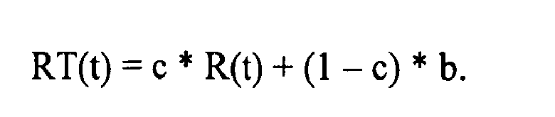
Hierbei nimmt c je nach Grad des Ausfüllens der Messzone 2 Werte zwischen 0 und 1 an. Für die relative Remission r(t) ergibt sich sodann: 
Ausgehend von den vorangehend beschriebenen Modellbetrachtungen wurden die in den Fig. 4 und 5 dargestellten zeitlichen Verläufe der Remission für verschiedenen Werte von c berechnet.Starting from the model considerations described above, the time courses of the remission shown in FIGS. 4 and 5 were calculated for different values of c.
Fig. 4 zeigt eine graphische Darstellung von berechneten Werten für einen zeitlichen Verlauf der Remission für unterschiedliche Füllgrade einer Messzone, d. h. Benetzungs- und / oder Befeuchtungsgrade, die sich durch verschiedene Werte für c ausdrücken. In Abhängigkeit von c, d. h. in Abhängigkeit von dem Füllmaß, verändert sich der Wert des Minimums 20 für die verschiedenen Remissionskurven. Ein Vergleich der berechneten Kurvenverläufe mit experimentell ermittelten Messgrößen, die im Rahmen der photometrischen Füllmessung für die Messzone 2 ermittelt werden, erlaubt so die Ermittlung des Füllmaßes für die Messzone 2.FIG. 4 shows a graphical representation of calculated values for a time course of the remission for different filling levels of a measuring zone, that is, FIG. H. Wetting and / or moistening levels expressed by different values of c. Depending on c, d. H. depending on the filling size, the value of the minimum 20 changes for the different remission curves. A comparison of the calculated curves with experimentally determined measured variables, which are determined in the context of the photometric filling measurement for the measuring
Fig. 5 zeigt eine graphische Darstellung der zeitlichen Ableitung für die Kurvenverläufe in Fig. 4. Der Nulldurchgang erfolgt für alle Kurven in einem Punkt, welcher dem Minimum 20 in der graphischen Darstellung in Fig. 4 entspricht.FIG. 5 shows a plot of the time derivative for the curves in FIG. 4. The zero crossing occurs for all curves at a point which corresponds to the minimum 20 in the graph in FIG.
Neben dem Wert für das Minimum 20 können auch andere Eigenschaften der Remissionsverläufe als Maß für den Grad des Füllens der Messzone 2 genutzt werden, beispielsweise Steigung oder Abfall der Remission. Hieraus können wahlweise auch Information über die Geschwindigkeit des Füllens der Messzone durch die Probe der Flüssigkeit abgeleitet werden.In addition to the value for the minimum 20, other properties of the remission curves can also be used as a measure of the degree of filling of the measuring
Das Verfahren zum Bestimmen der Benetzung / Befeuchtung der Messzone wurde vorangehend anhand von Remissionsmessungen erläutert. In analoger Weise können Messdaten für die Transmission oder die Absorption ausgewertet werden, wenn diese bei einer geeigneten (isobestischen) Messlichtwellenlänge durchgeführt werden. Geeignete Messlichtwellenlängen können je nach Anwendungsfall aus Vorexperimenten bestimmt werden oder sind dem Fachmann für bestimmten chemische Zusammensetzung bekannt. In analoger Weise verhält es sich mit eventuellen Abhängigkeiten der Verläufe der spektroskopischen Messgröße bei der gewählten Messlichtwellenlänge von anderen Parametern, zum Beispiel der Temperatur oder der Luftfeuchtigkeit.The method of determining the wetting / wetting of the measuring zone has been explained above on the basis of remission measurements. In an analogous manner, measurement data for the transmission or the absorption can be evaluated if these are carried out at a suitable (isobestic) measuring light wavelength. Suitable measuring light wavelengths can be determined depending on the application from previous experiments or are known to the expert for certain chemical composition. In an analogous way, it is with any dependencies of the curves of the spectroscopic measured variable at the selected measuring light wavelength of other parameters, for example, the temperature or humidity.
Mit dem beschriebenen Verfahren ist eine in beliebigen Messanordnungen vorteilhaft einsetzbare Möglichkeit geschaffen, den Füllgrad eines von einer Flüssigkeit einzunehmenden Bereiches, bevorzugt einer zu befeuchtenden oder zu benetzenden Fläche, zu ermitteln.With the method described, it is possible to advantageously use a possibility that can be used in any desired measuring arrangement, to determine the degree of filling of a region to be occupied by a liquid, preferably a surface to be moistened or wetted.
Messzone und Detektionszone können getrennt oder zumindest teilweise überlappend gebildet sein.Measuring zone and detection zone can be formed separately or at least partially overlapping.
Aufgrund des integralen Charakters des erfindungsgemäßen Verfahrens weist es gegenüber den bekannten Verfahren, insbesondere den mit einer Beleuchtungs- und Abbildungsoptik arbeitenden Spot-Messungen den Vorteil auf, dass es eine zuverlässige Benetzungserkennung ohne ortsaufgelöste Messung ermöglicht. Das erfindungsgemäße Verfahren ist daher prinzipiell unabhängig von der Form der Mess- bzw. Detektionsfläche, sofern diese homogen beleuchtet werden.Due to the integral nature of the method according to the invention, it has the advantage over the known methods, in particular the spot measurements operating with illumination and imaging optics, that it permits reliable wetting detection without spatially resolved measurement. The inventive method is therefore in principle independent of the shape of the measuring or detection surface, provided that they are illuminated homogeneously.
Die in der vorstehenden Beschreibung, den Ansprüchen und der Zeichnung offenbarten Merkmale der Erfindung können sowohl einzeln als auch in beliebiger Kombination für die Verwirklichung der Erfindung in ihren verschiedenen Ausführungsformen von Bedeutung sein.The features of the invention disclosed in the foregoing description, in the claims and in the drawing may be of importance both individually and in any combination for the realization of the invention in its various embodiments.
Claims (14)
Priority Applications (1)
| Application Number | Priority Date | Filing Date | Title |
|---|---|---|---|
| EP07013307.9A EP1890133B1 (en) | 2006-08-16 | 2007-07-06 | Method for analysing the sample of a liquid |
Applications Claiming Priority (2)
| Application Number | Priority Date | Filing Date | Title |
|---|---|---|---|
| EP06017021A EP1890132A1 (en) | 2006-08-16 | 2006-08-16 | Method for analysing a sample of a liquid |
| EP07013307.9A EP1890133B1 (en) | 2006-08-16 | 2007-07-06 | Method for analysing the sample of a liquid |
Publications (3)
| Publication Number | Publication Date |
|---|---|
| EP1890133A2 true EP1890133A2 (en) | 2008-02-20 |
| EP1890133A3 EP1890133A3 (en) | 2008-03-05 |
| EP1890133B1 EP1890133B1 (en) | 2016-10-12 |
Family
ID=38952028
Family Applications (1)
| Application Number | Title | Priority Date | Filing Date |
|---|---|---|---|
| EP07013307.9A Not-in-force EP1890133B1 (en) | 2006-08-16 | 2007-07-06 | Method for analysing the sample of a liquid |
Country Status (1)
| Country | Link |
|---|---|
| EP (1) | EP1890133B1 (en) |
Citations (2)
| Publication number | Priority date | Publication date | Assignee | Title |
|---|---|---|---|---|
| US4420566A (en) | 1982-06-10 | 1983-12-13 | Eastman Kodak Company | Method and apparatus for detecting sample fluid on an analysis slide |
| WO2003023499A2 (en) | 2001-09-12 | 2003-03-20 | Tecan Trading Ag | Optical device, system and use thereof |
Family Cites Families (4)
| Publication number | Priority date | Publication date | Assignee | Title |
|---|---|---|---|---|
| US5114350A (en) * | 1989-03-08 | 1992-05-19 | Cholestech Corporation | Controlled-volume assay apparatus |
| US6069011A (en) * | 1997-12-10 | 2000-05-30 | Umm Electronics, Inc. | Method for determining the application of a sample fluid on an analyte strip using first and second derivatives |
| ATE225142T1 (en) * | 1998-07-07 | 2002-10-15 | Lightouch Medical Inc | TISSUE MODULATION METHOD FOR QUANTITATIVE NON-INVASIVE IN VIVO SPECTROSCOPIC ANALYSIS OF TISSUE |
| DE19844500A1 (en) * | 1998-09-29 | 2000-03-30 | Roche Diagnostics Gmbh | Process for the photometric evaluation of test elements |
-
2007
- 2007-07-06 EP EP07013307.9A patent/EP1890133B1/en not_active Not-in-force
Patent Citations (2)
| Publication number | Priority date | Publication date | Assignee | Title |
|---|---|---|---|---|
| US4420566A (en) | 1982-06-10 | 1983-12-13 | Eastman Kodak Company | Method and apparatus for detecting sample fluid on an analysis slide |
| WO2003023499A2 (en) | 2001-09-12 | 2003-03-20 | Tecan Trading Ag | Optical device, system and use thereof |
Also Published As
| Publication number | Publication date |
|---|---|
| EP1890133B1 (en) | 2016-10-12 |
| EP1890133A3 (en) | 2008-03-05 |
Similar Documents
| Publication | Publication Date | Title |
|---|---|---|
| EP1890132A1 (en) | Method for analysing a sample of a liquid | |
| DE60113105T2 (en) | DEVICE FOR MEASURING THE CONCENTRATION OF GLUCOSE OR OTHER SUBSTANCES IN BLOOD | |
| DE102006025714B4 (en) | Apparatus and method for discriminating among lateral flow assay test indicators | |
| EP1843148B1 (en) | Analysis of optical data using histograms | |
| DE4417639A1 (en) | Analysis of concns. of substances in a biological sample | |
| EP2710348B1 (en) | Method and system for determining the concentration of substances in bodily fluids | |
| EP1166088B1 (en) | Method of ir-optically determining the concentration of at least one analyte in a liquid sample | |
| WO1981000622A1 (en) | Process and device of molecular spectroscopy particularly for determining metabolites | |
| WO2003083458A2 (en) | Infrared measuring device, especially for the spectrometry of aqueous systems, preferably multiple component systems | |
| EP2003441A1 (en) | ATR sensor | |
| EP3095384A1 (en) | Method and device for the non-invasive determination of a measurement parameter of an analyte in a biological body | |
| EP2956758B1 (en) | Method and device for determining the concentration of a fluorescent substance in a medium | |
| EP2579911B1 (en) | Dialysis assembly with a detection device | |
| DE10248555B4 (en) | Method and analysis system for determining the concentration of an analyte in a sample, which consists of the analyte and the sample matrix, and test element therefor | |
| EP2131197B1 (en) | Device for determining an analyte in a fluid sample and analysis device | |
| WO2000067547A2 (en) | Method for detecting serum and for determining the quality thereof, and corresponding devices | |
| EP2502054B1 (en) | Method and device for inspecting a bodily fluid | |
| EP2636751A2 (en) | Method for determining a body fluid | |
| EP3591378B1 (en) | Method for assaying lipids, haemoglobin and bilirubin in body fluid samples | |
| EP1890133B1 (en) | Method for analysing the sample of a liquid | |
| DE102011012674B3 (en) | Method for determination of approximation value of glomerular filtration rate during treatment of nephropathy for e.g. diabetic patients, involves determining content of albumin or its ratio to creatinine, where ratio represents parameter | |
| DE102015009863A1 (en) | Method and device for the non-invasive determination of a measurand of an analyte in a biological body | |
| DE102018204744A1 (en) | Chemical analysis device for measuring the ion concentration of an electrolyte and method for its operation | |
| DE19629992A1 (en) | Method and device for determining the absorbance of light radiation when penetrating a sample | |
| DE10214781A1 (en) | Infrared spectrometry device, especially for the spectrometry of aqueous systems, comprises an attenuated total reflection body and an infrared source with the ATR body configured to provide total internal reflection |
Legal Events
| Date | Code | Title | Description |
|---|---|---|---|
| PUAI | Public reference made under article 153(3) epc to a published international application that has entered the european phase |
Free format text: ORIGINAL CODE: 0009012 |
|
| PUAL | Search report despatched |
Free format text: ORIGINAL CODE: 0009013 |
|
| AK | Designated contracting states |
Kind code of ref document: A2 Designated state(s): AT BE BG CH CY CZ DE DK EE ES FI FR GB GR HU IE IS IT LI LT LU LV MC MT NL PL PT RO SE SI SK TR |
|
| AX | Request for extension of the european patent |
Extension state: AL BA HR MK YU |
|
| AK | Designated contracting states |
Kind code of ref document: A3 Designated state(s): AT BE BG CH CY CZ DE DK EE ES FI FR GB GR HU IE IS IT LI LT LU LV MC MT NL PL PT RO SE SI SK TR |
|
| AX | Request for extension of the european patent |
Extension state: AL BA HR MK YU |
|
| 17P | Request for examination filed |
Effective date: 20080526 |
|
| AKX | Designation fees paid |
Designated state(s): AT BE BG CH CY CZ DE DK EE ES FI FR GB GR HU IE IS IT LI LT LU LV MC MT NL PL PT RO SE SI SK TR |
|
| 17Q | First examination report despatched |
Effective date: 20090526 |
|
| REG | Reference to a national code |
Ref country code: DE Ref legal event code: R079 Ref document number: 502007015177 Country of ref document: DE Free format text: PREVIOUS MAIN CLASS: G01N0021860000 Ipc: G01N0021840000 |
|
| GRAP | Despatch of communication of intention to grant a patent |
Free format text: ORIGINAL CODE: EPIDOSNIGR1 |
|
| RIC1 | Information provided on ipc code assigned before grant |
Ipc: G01N 21/84 20060101AFI20160310BHEP |
|
| INTG | Intention to grant announced |
Effective date: 20160322 |
|
| GRAS | Grant fee paid |
Free format text: ORIGINAL CODE: EPIDOSNIGR3 |
|
| RIN1 | Information on inventor provided before grant (corrected) |
Inventor name: STEFAN, KALVERAM Inventor name: JEAN-MICHEL, ASFOUR Inventor name: FREDERIC, WEHOWSKI Inventor name: BERND, ROESICKE |
|
| GRAA | (expected) grant |
Free format text: ORIGINAL CODE: 0009210 |
|
| RAP1 | Party data changed (applicant data changed or rights of an application transferred) |
Owner name: F. HOFFMANN-LA ROCHE AG Owner name: ROCHE DIAGNOSTICS GMBH |
|
| AK | Designated contracting states |
Kind code of ref document: B1 Designated state(s): AT BE BG CH CY CZ DE DK EE ES FI FR GB GR HU IE IS IT LI LT LU LV MC MT NL PL PT RO SE SI SK TR |
|
| REG | Reference to a national code |
Ref country code: GB Ref legal event code: FG4D Free format text: NOT ENGLISH |
|
| REG | Reference to a national code |
Ref country code: CH Ref legal event code: EP |
|
| REG | Reference to a national code |
Ref country code: AT Ref legal event code: REF Ref document number: 836965 Country of ref document: AT Kind code of ref document: T Effective date: 20161015 |
|
| REG | Reference to a national code |
Ref country code: IE Ref legal event code: FG4D Free format text: LANGUAGE OF EP DOCUMENT: GERMAN |
|
| REG | Reference to a national code |
Ref country code: DE Ref legal event code: R096 Ref document number: 502007015177 Country of ref document: DE |
|
| REG | Reference to a national code |
Ref country code: LT Ref legal event code: MG4D |
|
| REG | Reference to a national code |
Ref country code: NL Ref legal event code: MP Effective date: 20161012 |
|
| PG25 | Lapsed in a contracting state [announced via postgrant information from national office to epo] |
Ref country code: LV Free format text: LAPSE BECAUSE OF FAILURE TO SUBMIT A TRANSLATION OF THE DESCRIPTION OR TO PAY THE FEE WITHIN THE PRESCRIBED TIME-LIMIT Effective date: 20161012 |
|
| PG25 | Lapsed in a contracting state [announced via postgrant information from national office to epo] |
Ref country code: LT Free format text: LAPSE BECAUSE OF FAILURE TO SUBMIT A TRANSLATION OF THE DESCRIPTION OR TO PAY THE FEE WITHIN THE PRESCRIBED TIME-LIMIT Effective date: 20161012 Ref country code: GR Free format text: LAPSE BECAUSE OF FAILURE TO SUBMIT A TRANSLATION OF THE DESCRIPTION OR TO PAY THE FEE WITHIN THE PRESCRIBED TIME-LIMIT Effective date: 20170113 Ref country code: SE Free format text: LAPSE BECAUSE OF FAILURE TO SUBMIT A TRANSLATION OF THE DESCRIPTION OR TO PAY THE FEE WITHIN THE PRESCRIBED TIME-LIMIT Effective date: 20161012 |
|
| PG25 | Lapsed in a contracting state [announced via postgrant information from national office to epo] |
Ref country code: PL Free format text: LAPSE BECAUSE OF FAILURE TO SUBMIT A TRANSLATION OF THE DESCRIPTION OR TO PAY THE FEE WITHIN THE PRESCRIBED TIME-LIMIT Effective date: 20161012 Ref country code: IS Free format text: LAPSE BECAUSE OF FAILURE TO SUBMIT A TRANSLATION OF THE DESCRIPTION OR TO PAY THE FEE WITHIN THE PRESCRIBED TIME-LIMIT Effective date: 20170212 Ref country code: PT Free format text: LAPSE BECAUSE OF FAILURE TO SUBMIT A TRANSLATION OF THE DESCRIPTION OR TO PAY THE FEE WITHIN THE PRESCRIBED TIME-LIMIT Effective date: 20170213 Ref country code: FI Free format text: LAPSE BECAUSE OF FAILURE TO SUBMIT A TRANSLATION OF THE DESCRIPTION OR TO PAY THE FEE WITHIN THE PRESCRIBED TIME-LIMIT Effective date: 20161012 Ref country code: NL Free format text: LAPSE BECAUSE OF FAILURE TO SUBMIT A TRANSLATION OF THE DESCRIPTION OR TO PAY THE FEE WITHIN THE PRESCRIBED TIME-LIMIT Effective date: 20161012 Ref country code: ES Free format text: LAPSE BECAUSE OF FAILURE TO SUBMIT A TRANSLATION OF THE DESCRIPTION OR TO PAY THE FEE WITHIN THE PRESCRIBED TIME-LIMIT Effective date: 20161012 |
|
| REG | Reference to a national code |
Ref country code: DE Ref legal event code: R097 Ref document number: 502007015177 Country of ref document: DE |
|
| PG25 | Lapsed in a contracting state [announced via postgrant information from national office to epo] |
Ref country code: RO Free format text: LAPSE BECAUSE OF FAILURE TO SUBMIT A TRANSLATION OF THE DESCRIPTION OR TO PAY THE FEE WITHIN THE PRESCRIBED TIME-LIMIT Effective date: 20161012 Ref country code: SK Free format text: LAPSE BECAUSE OF FAILURE TO SUBMIT A TRANSLATION OF THE DESCRIPTION OR TO PAY THE FEE WITHIN THE PRESCRIBED TIME-LIMIT Effective date: 20161012 Ref country code: DK Free format text: LAPSE BECAUSE OF FAILURE TO SUBMIT A TRANSLATION OF THE DESCRIPTION OR TO PAY THE FEE WITHIN THE PRESCRIBED TIME-LIMIT Effective date: 20161012 Ref country code: EE Free format text: LAPSE BECAUSE OF FAILURE TO SUBMIT A TRANSLATION OF THE DESCRIPTION OR TO PAY THE FEE WITHIN THE PRESCRIBED TIME-LIMIT Effective date: 20161012 Ref country code: CZ Free format text: LAPSE BECAUSE OF FAILURE TO SUBMIT A TRANSLATION OF THE DESCRIPTION OR TO PAY THE FEE WITHIN THE PRESCRIBED TIME-LIMIT Effective date: 20161012 |
|
| PLBE | No opposition filed within time limit |
Free format text: ORIGINAL CODE: 0009261 |
|
| STAA | Information on the status of an ep patent application or granted ep patent |
Free format text: STATUS: NO OPPOSITION FILED WITHIN TIME LIMIT |
|
| PG25 | Lapsed in a contracting state [announced via postgrant information from national office to epo] |
Ref country code: IT Free format text: LAPSE BECAUSE OF FAILURE TO SUBMIT A TRANSLATION OF THE DESCRIPTION OR TO PAY THE FEE WITHIN THE PRESCRIBED TIME-LIMIT Effective date: 20161012 Ref country code: BG Free format text: LAPSE BECAUSE OF FAILURE TO SUBMIT A TRANSLATION OF THE DESCRIPTION OR TO PAY THE FEE WITHIN THE PRESCRIBED TIME-LIMIT Effective date: 20170112 |
|
| 26N | No opposition filed |
Effective date: 20170713 |
|
| PG25 | Lapsed in a contracting state [announced via postgrant information from national office to epo] |
Ref country code: SI Free format text: LAPSE BECAUSE OF FAILURE TO SUBMIT A TRANSLATION OF THE DESCRIPTION OR TO PAY THE FEE WITHIN THE PRESCRIBED TIME-LIMIT Effective date: 20161012 |
|
| REG | Reference to a national code |
Ref country code: CH Ref legal event code: PL |
|
| GBPC | Gb: european patent ceased through non-payment of renewal fee |
Effective date: 20170706 |
|
| REG | Reference to a national code |
Ref country code: DE Ref legal event code: R082 Ref document number: 502007015177 Country of ref document: DE Ref country code: DE Ref legal event code: R081 Ref document number: 502007015177 Country of ref document: DE Owner name: ROCHE DIABETES CARE GMBH, DE Free format text: FORMER OWNER: ROCHE DIAGNOSTICS GMBH, 68305 MANNHEIM, DE |
|
| REG | Reference to a national code |
Ref country code: IE Ref legal event code: MM4A |
|
| REG | Reference to a national code |
Ref country code: FR Ref legal event code: ST Effective date: 20180330 |
|
| PG25 | Lapsed in a contracting state [announced via postgrant information from national office to epo] |
Ref country code: LI Free format text: LAPSE BECAUSE OF NON-PAYMENT OF DUE FEES Effective date: 20170731 Ref country code: GB Free format text: LAPSE BECAUSE OF NON-PAYMENT OF DUE FEES Effective date: 20170706 Ref country code: CH Free format text: LAPSE BECAUSE OF NON-PAYMENT OF DUE FEES Effective date: 20170731 Ref country code: IE Free format text: LAPSE BECAUSE OF NON-PAYMENT OF DUE FEES Effective date: 20170706 |
|
| PG25 | Lapsed in a contracting state [announced via postgrant information from national office to epo] |
Ref country code: FR Free format text: LAPSE BECAUSE OF NON-PAYMENT OF DUE FEES Effective date: 20170731 |
|
| REG | Reference to a national code |
Ref country code: BE Ref legal event code: MM Effective date: 20170731 |
|
| PG25 | Lapsed in a contracting state [announced via postgrant information from national office to epo] |
Ref country code: LU Free format text: LAPSE BECAUSE OF NON-PAYMENT OF DUE FEES Effective date: 20170706 |
|
| PG25 | Lapsed in a contracting state [announced via postgrant information from national office to epo] |
Ref country code: BE Free format text: LAPSE BECAUSE OF NON-PAYMENT OF DUE FEES Effective date: 20170731 |
|
| REG | Reference to a national code |
Ref country code: AT Ref legal event code: MM01 Ref document number: 836965 Country of ref document: AT Kind code of ref document: T Effective date: 20170706 |
|
| PG25 | Lapsed in a contracting state [announced via postgrant information from national office to epo] |
Ref country code: MT Free format text: LAPSE BECAUSE OF FAILURE TO SUBMIT A TRANSLATION OF THE DESCRIPTION OR TO PAY THE FEE WITHIN THE PRESCRIBED TIME-LIMIT Effective date: 20161012 |
|
| PG25 | Lapsed in a contracting state [announced via postgrant information from national office to epo] |
Ref country code: AT Free format text: LAPSE BECAUSE OF NON-PAYMENT OF DUE FEES Effective date: 20170706 |
|
| PG25 | Lapsed in a contracting state [announced via postgrant information from national office to epo] |
Ref country code: MC Free format text: LAPSE BECAUSE OF FAILURE TO SUBMIT A TRANSLATION OF THE DESCRIPTION OR TO PAY THE FEE WITHIN THE PRESCRIBED TIME-LIMIT Effective date: 20161012 Ref country code: HU Free format text: LAPSE BECAUSE OF FAILURE TO SUBMIT A TRANSLATION OF THE DESCRIPTION OR TO PAY THE FEE WITHIN THE PRESCRIBED TIME-LIMIT; INVALID AB INITIO Effective date: 20070706 |
|
| PG25 | Lapsed in a contracting state [announced via postgrant information from national office to epo] |
Ref country code: CY Free format text: LAPSE BECAUSE OF NON-PAYMENT OF DUE FEES Effective date: 20161012 |
|
| PGFP | Annual fee paid to national office [announced via postgrant information from national office to epo] |
Ref country code: DE Payment date: 20190617 Year of fee payment: 13 |
|
| PG25 | Lapsed in a contracting state [announced via postgrant information from national office to epo] |
Ref country code: TR Free format text: LAPSE BECAUSE OF FAILURE TO SUBMIT A TRANSLATION OF THE DESCRIPTION OR TO PAY THE FEE WITHIN THE PRESCRIBED TIME-LIMIT Effective date: 20161012 |
|
| REG | Reference to a national code |
Ref country code: DE Ref legal event code: R119 Ref document number: 502007015177 Country of ref document: DE |
|
| PG25 | Lapsed in a contracting state [announced via postgrant information from national office to epo] |
Ref country code: DE Free format text: LAPSE BECAUSE OF NON-PAYMENT OF DUE FEES Effective date: 20210202 |