EP1892476A2 - Slide-out half rack - Google Patents
Slide-out half rack Download PDFInfo
- Publication number
- EP1892476A2 EP1892476A2 EP07016263A EP07016263A EP1892476A2 EP 1892476 A2 EP1892476 A2 EP 1892476A2 EP 07016263 A EP07016263 A EP 07016263A EP 07016263 A EP07016263 A EP 07016263A EP 1892476 A2 EP1892476 A2 EP 1892476A2
- Authority
- EP
- European Patent Office
- Prior art keywords
- rack
- auxiliary
- section
- platform area
- auxiliary section
- Prior art date
- Legal status (The legal status is an assumption and is not a legal conclusion. Google has not performed a legal analysis and makes no representation as to the accuracy of the status listed.)
- Withdrawn
Links
- 235000013305 food Nutrition 0.000 description 8
- 239000000463 material Substances 0.000 description 8
- 229910052751 metal Inorganic materials 0.000 description 6
- 239000002184 metal Substances 0.000 description 6
- 238000005728 strengthening Methods 0.000 description 4
- 238000000034 method Methods 0.000 description 3
- 238000007665 sagging Methods 0.000 description 3
- XEEYBQQBJWHFJM-UHFFFAOYSA-N Iron Chemical compound [Fe] XEEYBQQBJWHFJM-UHFFFAOYSA-N 0.000 description 2
- PXHVJJICTQNCMI-UHFFFAOYSA-N Nickel Chemical compound [Ni] PXHVJJICTQNCMI-UHFFFAOYSA-N 0.000 description 2
- 238000010411 cooking Methods 0.000 description 2
- 235000014510 cooky Nutrition 0.000 description 2
- 238000001816 cooling Methods 0.000 description 2
- 230000004048 modification Effects 0.000 description 2
- 238000012986 modification Methods 0.000 description 2
- 235000013550 pizza Nutrition 0.000 description 2
- 229910052573 porcelain Inorganic materials 0.000 description 2
- 238000003466 welding Methods 0.000 description 2
- 229910000831 Steel Inorganic materials 0.000 description 1
- 239000000853 adhesive Substances 0.000 description 1
- 230000001070 adhesive effect Effects 0.000 description 1
- 229910052782 aluminium Inorganic materials 0.000 description 1
- XAGFODPZIPBFFR-UHFFFAOYSA-N aluminium Chemical compound [Al] XAGFODPZIPBFFR-UHFFFAOYSA-N 0.000 description 1
- 235000015173 baked goods and baking mixes Nutrition 0.000 description 1
- 239000000919 ceramic Substances 0.000 description 1
- 238000004140 cleaning Methods 0.000 description 1
- 238000000576 coating method Methods 0.000 description 1
- 238000010276 construction Methods 0.000 description 1
- 238000010438 heat treatment Methods 0.000 description 1
- 229910052742 iron Inorganic materials 0.000 description 1
- 230000007246 mechanism Effects 0.000 description 1
- 229910052759 nickel Inorganic materials 0.000 description 1
- 229920001296 polysiloxane Polymers 0.000 description 1
- 239000010959 steel Substances 0.000 description 1
- 230000007704 transition Effects 0.000 description 1
- 230000007723 transport mechanism Effects 0.000 description 1
Images


Classifications
-
- F—MECHANICAL ENGINEERING; LIGHTING; HEATING; WEAPONS; BLASTING
- F24—HEATING; RANGES; VENTILATING
- F24C—DOMESTIC STOVES OR RANGES ; DETAILS OF DOMESTIC STOVES OR RANGES, OF GENERAL APPLICATION
- F24C15/00—Details
- F24C15/16—Shelves, racks or trays inside ovens; Supports therefor
Definitions
- the present invention relates to racks for appliances, and more particularly, to a slide-out half rack for an oven.
- Ovens often have one or more racks generally within the oven.
- the racks are useful for the placing of cookware, food, and other items, within the oven.
- the racks place the cookware generally towards the middle of the oven, and keep the cookware away from heating elements and the like.
- ovens with multiple racks allow for placement of cookware on a variety of levels within the oven, thereby increasing the total volume of available cooking space.
- the racks are often supported by ledges formed along the inner walls of the oven.
- the racks are then movable in and out of the oven on the ledges. This allows the racks to be removed from the oven for cleaning or for other purposes. Often, the racks may be partially removed from the oven so as to allow easier access to items placed on the racks.
- the ledges also facilitate vertical adjustment of the racks within the oven cavity.
- Oven racks are often of wire form construction. More specifically, an outer wire frame and a support platform, which is constituted by a plurality of fore-to-aft and laterally spaced wires, define a typical oven rack. The wires are substantially evenly spaced across the entire rack for use in supporting food items to be cooked.
- a slide-out half rack for an appliance includes a main section including a primary platform area and a secondary platform area.
- the primary platform area includes a plurality of elongated support bars and at least one cross member provided across a portion of the primary platform area to provide strength.
- An auxiliary section has an auxiliary platform area and is adapted to be slidably received by the main section to move between a retracted position and an extended position.
- the auxiliary platform is adapted to support various items independent of whether it is in retracted position or the extended position.
- a slide-out half rack in accordance with another aspect of the present invention, includes a main section having a primary platform area extending along a first plane and a secondary platform area extending along a second plane.
- the second plane is located below the first plane to form a recessed area.
- An auxiliary section has an auxiliary platform area and is adapted to be slidably received by the recessed area.
- the auxiliary section is adapted to be removable from the main section.
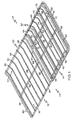
- Figure 1 illustrates a perspective view of an example of a slide-out half rack having a main section and an auxiliary section in accordance with an aspect of the present invention
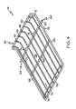
- Figure 2 illustrates a perspective view of the example slide-out half rack of Figure 1 in accordance with another aspect of the present invention
- Figure 3 illustrates a perspective view of the main section of the slide-out half rack of Figure 1 in accordance with an aspect of the present invention
- Figure 4 illustrates a perspective view of the auxiliary section of the slide-out half rack of Figure 1 in accordance with an aspect of the present invention
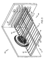
- Figure 5 illustrates a perspective view of the slide-out half rack in an oven environment with the auxiliary section in a retracted position
- Figure 6 is similar to Figure 5, but shows the auxiliary section in an extended position.
- the present invention relates to a slide-out half rack for an oven.
- the present invention will now be described with reference to the drawings, wherein like reference numerals are used to refer to like elements throughout. It is to be appreciated that the various drawings are not necessarily drawn to scale from one figure to another nor inside a given figure, and in particular that the size of the components are arbitrarily drawn for facilitating the understanding of the drawings. In the following description, for purposes of explanation, numerous specific details are set forth in order to provide a thorough understanding of the present invention. It may be evident, however, that the present invention may be practiced without these specific details.
- the rack 10 includes a main section 12 and an auxiliary section 14.
- the auxiliary section 14 can be relatively smaller than the main section 12 (e.g., occupying a partial area of the rack 10).
- Both the main section 12 and the auxiliary section 14 can be constructed from metal wire, such as iron coated with nickel or steel coated with porcelain.
- metal wire such as iron coated with nickel or steel coated with porcelain.
- either, or both of the main section 12 and the auxiliary section 14 can be constructed from various other suitable materials (e.g., aluminum, sheet metal, or the like).
- the main section 12 can be constructed from a first material and the auxiliary section 14 can be constructed from a second different material.
- the auxiliary section 14 is adapted to be slidably received by the main section 12, as shown in FIG. 2 and as will be discussed more fully herein.
- the main section 12 can include a primary platform area 16 and a secondary platform area 18.
- the rack 10 can include a support frame 22, and a plurality of elongated support bars 20 can extend across the support frame 22 to form the primary platform area 16.
- the frame can include a front bar 24, rear bar 26, and apposed side bars 28, 30 that can be attached together to form the support frame 22 in various manners, such as by welding, adhesives, or fasteners, and/or can even be formed from a single piece of wire.
- the elongated support bars 20 can extend between the front bar 24 and the rear bar 26, though it is to be appreciated that the support bars 20 can also be oriented in various manners.
- the support frame 22 can have a generally rectangular geometry, through it is to be appreciated that the support frame 22 can also have various other geometries.
- the rear bar 26 of the support frame 22 can be located at a relatively higher position with respect to the front bar 24.
- a portion of the support members 20 attached to the rear bar 26 can act as a stop 27 to limit the extent to which an item can be inserted into an oven cavity.
- the main section 12 can include an additional platform area (not shown) located adjacent the rear bar 26 to provide support for even larger items.
- the rack 10 can include at least one cross member 32 or strengthening member provided across a portion of the primary platform 16 area to provide strength.
- the cross member(s) 32 operate to mitigate sagging of the primary platform area 16 with respect to the front bar 24 when heavy food, cookware, or the like (not shown) is placed on the primary platform area 16. Sagging of the primary platform area 16 presents problems with easily sliding the food or cookware from the primary platform area 16 without interference from the front bar 24.
- the ends of the support members 20 and/or the cross member 32 can be welded (e.g., spot welded), otherwise secured to, or even formed together as a single unit with, the various portions of the rack 10.
- the support members 20, frame 22, and/or cross member 32 can be manufactured from metal wire or any other suitable material which provides adequate strength to support items such as cake pans, pizza stones and casseroles, or the like, and withstands the heat of an oven. It is to be appreciated that the cross members 32 can be oriented in various other manners, including transverse or angled relative to the elongated support members 20.
- the secondary platform area 18 can include at least one elongated support member 34, and can also include one or more cross members (not shown).
- the support members 20 of the primary platform area 16 can extend substantially parallel to each other such that the primary platform area 16 substantially extends along a first plane 36.
- the support members 34 of the secondary platform area 18 can extend substantially parallel to each other such that the second platform area 18 extends along a second plane 38.
- the second plane 38 can be located below the first plane 36 to form a recessed area 40, as will be discussed more fully herein.
- the rack 10 also includes an auxiliary section 14 having an auxiliary platform area 42.
- the auxiliary section 14 can be adapted to be slidably received by the main section 12 to be moved between a retracted position 44, as shown in FIG. 1, and an extended position 46, as shown in FIG. 2.
- the auxiliary section 14 is adapted to support various items, such as cookware, food, and other items, within the oven. Further, the auxiliary section 14 can be adapted to support various items independent of whether it is in the retracted position 44 or the extended position 46.
- the auxiliary section 14 in the retracted position 44, can be adapted to support various items, such as a large cookie sheet, in conjunction with the primary platform area 16, though it is to be appreciated that the auxiliary section 14 can also support the item independently.
- the auxiliary section 14 when in the extended position 46, or when in the transition between the retracted and extended positions 44, 46, can also be adapted to independently support various items.
- the main section 12 of the rack 10 can be adapted to move between a retracted and an extended position (not shown) relative to the oven cavity 84 (see FIG. 5), and the auxiliary section 14 can be further adapted to independently support various items regardless of the positioning of the main section 12.
- the auxiliary section 14 can be adapted to support various items when it is in a "double extended" position (i.e., the main section 12 is extended from the oven cavity 84, and the auxiliary section 14 is further extended away from the main section 12).
- the auxiliary platform area 42 can also include a plurality of elongated support bars 48.
- the auxiliary platform area 42 can include a support frame 50, and the elongated support bars 48 can extend across the support frame 50.
- the frame 50 can include a front bar 52, rear bar 54, and apposed side bars 56, 58, and the elongated support bars 48 can extend between the front bar 52 and the rear bar 54, though it is to be appreciated that the support bars 48 can be oriented in various other manners.
- auxiliary section 14 can be configured to include various geometries, such as, for example, square, rectangular, triangular, polygonal, circular, oval and/or elliptical, and the rack 10 can even include a plurality of auxiliary sections 14 (not shown).
- the auxiliary section 14 can include at least one cross member 60 or strengthening member provided across a portion of the auxiliary platform 42 area to provide strength.
- the cross member(s) 60 operate to mitigate sagging of the auxiliary platform area 42 with respect to the front bar 52 when heavy food, cookware, or the like is placed on the auxiliary platform area 60.
- the ends of the support members 48 and/or the cross member 60 can be welded (e.g., spot welded), otherwise secured to, or even formed together as a single unit with, the various portions of the auxiliary section 14.
- the support members 48, frame 50, and/or cross member 60 can be manufactured from metal wire or any other suitable material which provides adequate strength to support items such as cake pans, pizza stones and casseroles, or the like, and withstands the heat of an oven.
- the auxiliary section 14 can be adapted to slidably move relative to the main section 12 between a retracted position 44 and an extended position 46.
- the auxiliary section 14 can be adapted to telescope relative to the main section 12.
- the auxiliary section 14 can be adapted to move in an overlapping fashion relative to the secondary platform area 18.
- the auxiliary section 14 can comprise various structures to enable it to slidingly and/or telescopically move relative to the main section 12.
- the auxiliary section 14 can include an outwardly extending support bar 62 having at least one end 64 configured for sliding engagement with the main section 12.
- the outwardly extending support bar 62 can include two outwardly extending ends 64, 66.
- the ends 64, 66 of the outwardly extending support bar 62 can each extend a distance away from the side bars 56, 58, respectively.
- the outwardly extending support bar 62 can be disposed in various locations on the auxiliary section 14, and can also extend across a portion of the auxiliary support platform 42 and to as a strengthening support similar to the cross member 60.
- the main section 12 can also include at least one support wire 68 configured to define a horizontal travel path relative to the main section 12 for the end(s) 64, 66 of the outwardly extending support bar 62.
- the main section 12 can include a pair of support wires 68, 70 configured to define the horizontal travel path.
- the term horizontal refers to a direction perpendicular to the longitudinal extent of the rack 10, such that a user could slide the auxiliary rack 14 into and out of an appliance, such as into and out of an oven cavity 84 (see FIG. 5).
- the ends 64, 66 of the outwardly extending support bar 62 can be adapted to slide along the support wires 68, 70.
- the ends 64, 66 can be adapted to slide beneath the support wires 68, 70, though it is to be appreciated that the ends 64, 66 could also be adapted to slide above, or even in between, various configurations of support wires.
- the auxiliary section 14 can slide relative to the main section 12 using various other methods.
- the rack 10 could include known telescoping support slides (e.g., telescoping ball bearing support slides, or the like), a wheeled transport mechanism, or a sliding tongue and groove system, though various other methods could also be used.
- the auxiliary section 14 can also include various other features.
- the auxiliary section 14 can include at least one stop member 72 adapted to inhibit sliding motion of the auxiliary section 14.
- the auxiliary section 14 can include a pair of stop members 72 that are adapted to abut the front bar 24 of the support frame 22 of the main section 12 when the auxiliary section 14 is in the fully extended position 46.
- the elongated support members 48 of the auxiliary section can be configured to form a rear stop portion 73 configured to abut the rear bar 26 of the main support frame 22 when the auxiliary section 14 is in the fully retracted position 44.
- stop members 72 can cooperate with the ends 64, 66 and the support wires 68, 70 to prevent tipping of the auxiliary section 14 when it is in the extended position 46.
- Various other stop and/or anti-tipping mechanisms are also contemplated to be within the scope of this disclosure.
- the auxiliary platform can include at least one guide member 74 adapted to engage a portion of the secondary platform area 18.
- the outwardly extending support bar 62 of the auxiliary section 14 can include a pair of guide members 74.
- the guide members can comprise a rounded geometry adapted to slide upon the elongated support members 34 of the secondary platform area 18, though other guide members are also contemplated.
- the auxiliary platform 14 can include a handle portion 76 adapted to facilitate movement of the auxiliary platform from the retracted position 44 to the extended position 46.
- the handle 76 can be formed of a similar material as the main rack 12 (e.g., metal wire or the like) and can be attached to (e.g., welding or the like), or formed with, the front bar 52 of the auxiliary section 14.
- the handle 76 can also be disposed at various other locations, and can even be formed as part of the front bar 52.
- the handle 76 can be configured to be grasped to a hand of a user, and can include various coatings and/or a covering member (e.g., silicone, porcelain, ceramic, or the like) adapted to insulate a user's hand from the heat of an oven.
- a covering member e.g., silicone, porcelain, ceramic, or the like
- the main section 12 can also include a handle (not shown) to facilitate movement of the rack 10 relative to the oven cavity 84.
- the rack 10 can include a recessed area 40 formed by the secondary platform area 18.
- the auxiliary section 14 can be slidably received by the recessed area 40.
- the auxiliary section 14 can be configured to move (e.g., slide, move in a linear path, and/or telescope) within the recessed area 40 between the retracted and extended positions 44, 46.
- the recessed area 40 can be configured to include various geometries, such as for example, square, triangular, polygonal, circular, oval and/or elliptical that correspond to the geometry of the auxiliary section 14. It is to be appreciated that the recessed area 40 can also be configured to receive a plurality of auxiliary sections 14, and/or the rack 10 can even include a plurality of recessed areas 40 (not shown).
- the auxiliary platform area 42 can extend along a third plane 78 that is substantially co-planar to the first plane 36 of the primary platform area 16.
- the third plane 78 can be substantially co-planar with the first plane 36 such that the primary platform area 16 and the auxiliary platform area 42 can cooperate to support various foods or cookware within an appliance, such as in an oven cavity.
- the primary and auxiliary platform areas 16, 42 can cooperate to support a large cookie sheet or casserole dish (not shown).
- various items can be easily moved (e.g., slid) therebetween to facilitate removal from the oven cavity.
- the third plane 78 can also be oriented at various other heights relative to the first and/or second planes 36, 38.
- the auxiliary section 14 can be adapted to be removable from the main section 12.
- the auxiliary section 14 can be completely removed from the main section 12 such that the main section can remain within an oven while the auxiliary section 14 is removed therefrom.
- the auxiliary section 14 when the auxiliary section 14 is removed from the main section 12, it can be stored or used as a cooling rack for supporting hot items or baked goods on a counter top.
- the auxiliary section 14 can include a plurality of support legs and/or support feet (not shown) or the like to support the auxiliary section 14 about a counter if it is employed as a cooling rack. Since the auxiliary section 14 is relatively small and light, its removal from the main rack can be readily accomplished with little effort.
- the auxiliary section 14 can be removed from the main section 12 by orienting it at an angle relative to the main section 12 to release one of the ends 64, 66 of the outwardly extending support bar 62 from one of the support wires 68, 70 of the main section 12 to thereby disengage the auxiliary section 14 from the main section 12, though other methods of removal are also contemplated.
- the primary platform area 16 and the secondary platform area 18 can each be adapted to support various items (e.g., food to be cooked, cookware, or the like) independent of whether the auxiliary section 14 is removed from the main section 12.
- the primary platform section 16 can support various items regardless of whether the auxiliary section 14 is in the retracted or extended positions 44, 46, or is completely removed from the main section 12.
- the secondary platform area 18 can be adapted to support various items within an oven.
- the secondary platform area 18 includes the recessed area 40, relatively taller items can be placed on the secondary platform area 18 (e.g., items that might be too tall to be supported by the primary platform area 16).
- the secondary platform area 18 can include various strengthening members, such as larger support members 34 and/or the addition of cross members (not shown) or the like provided across a portion thereof.
- the rack 10 of the present invention is illustrated employed within an oven environment 80.
- the support frame 22 of the main section 12 can be supported by guide rails 82 within an oven cavity 84.
- the main section 12 can include an upward-facing projection 88 integrally formed in the wire frame of each of the sides 28, 30 of the support frame 22 to facilitate alignment of the rack 10 within the oven 80.
- the guide rails 82 of the oven 80 can have corresponding downward-facing projections 90.
- the upward-facing projections 88 of the main section 12 can be adapted to contact the downward-facing projections 90 of the top guide rails 82 such that a stop is created to properly align the main section 12 within the standard rack location of the oven 80.
- the primary platform area 16 of the main section 12 and the auxiliary platform area 42 of the auxiliary section 14 can be utilized to support various items for cooking within the oven.
- the rack 10 can be supported with in the oven cavity 84 in the retracted position 44.
- the rack 10 can also be similarly supported in the extended position 46.
- various items could be easily retrieved from the auxiliary section 14 without having to extend the main section 12.
- the auxiliary section 14 can be in the fully extended position 46 even when the rack 10 is also fully extended (not shown).
- various items can also be supported on other oven racks (not shown) simultaneously without the need to add or remove any other racks.
- the racks of the subject invention can be used in settings other than in an oven.
- the racks of the subject invention could be used in a refrigerator and/or freezer unit.
- the racks can be constructed of any suitable material, such as metal, plastic, and the like.
- the frame, the bars, and the cross-member(s) need not be constructed from the same materials.
- the size of the frame of the rack of the subject invention also depends upon the intended use of the rack.
- the rack is sized to slide into or replace a rack of a conventional oven.
- the bars are spaced to accommodate cookware.
- the frame can be made larger to fit commercial ovens or sized to fit any apparatus in which the racks are to be used.
- the bars of the rack can be spaced appropriately within the frame to hold any designated item.
Abstract
Description
- Not Applicable.
- The present invention relates to racks for appliances, and more particularly, to a slide-out half rack for an oven.
- Ovens often have one or more racks generally within the oven. The racks are useful for the placing of cookware, food, and other items, within the oven. The racks place the cookware generally towards the middle of the oven, and keep the cookware away from heating elements and the like. In addition, ovens with multiple racks allow for placement of cookware on a variety of levels within the oven, thereby increasing the total volume of available cooking space.
- The racks are often supported by ledges formed along the inner walls of the oven. The racks are then movable in and out of the oven on the ledges. This allows the racks to be removed from the oven for cleaning or for other purposes. Often, the racks may be partially removed from the oven so as to allow easier access to items placed on the racks. The ledges also facilitate vertical adjustment of the racks within the oven cavity.
- Oven racks are often of wire form construction. More specifically, an outer wire frame and a support platform, which is constituted by a plurality of fore-to-aft and laterally spaced wires, define a typical oven rack. The wires are substantially evenly spaced across the entire rack for use in supporting food items to be cooked.
- The following presents a simplified summary of the invention in order to provide a basic understanding of some aspects of the invention. This summary is not an extensive overview of the invention. It is intended to neither identify key or critical elements of the invention nor delineate the scope of the invention. Its sole purpose is to present some concepts of the invention in a simplified form as a prelude to the more detailed description that is presented later.
- In accordance with an aspect of the present invention, a slide-out half rack for an appliance is provided. The rack includes a main section including a primary platform area and a secondary platform area. The primary platform area includes a plurality of elongated support bars and at least one cross member provided across a portion of the primary platform area to provide strength. An auxiliary section has an auxiliary platform area and is adapted to be slidably received by the main section to move between a retracted position and an extended position. The auxiliary platform is adapted to support various items independent of whether it is in retracted position or the extended position.
- In accordance with another aspect of the present invention, a slide-out half rack is provided. The rack includes a main section having a primary platform area extending along a first plane and a secondary platform area extending along a second plane. The second plane is located below the first plane to form a recessed area. An auxiliary section has an auxiliary platform area and is adapted to be slidably received by the recessed area. The auxiliary section is adapted to be removable from the main section.
- The foregoing and other features and advantages of the present invention will become apparent to those skilled in the art to which the present invention relates upon reading the following description with reference to the accompanying drawings, in which:
- Figure 1 illustrates a perspective view of an example of a slide-out half rack having a main section and an auxiliary section in accordance with an aspect of the present invention;
- Figure 2 illustrates a perspective view of the example slide-out half rack of Figure 1 in accordance with another aspect of the present invention;
- Figure 3 illustrates a perspective view of the main section of the slide-out half rack of Figure 1 in accordance with an aspect of the present invention;
- Figure 4 illustrates a perspective view of the auxiliary section of the slide-out half rack of Figure 1 in accordance with an aspect of the present invention;
- Figure 5 illustrates a perspective view of the slide-out half rack in an oven environment with the auxiliary section in a retracted position; and
- Figure 6 is similar to Figure 5, but shows the auxiliary section in an extended position.
- The present invention relates to a slide-out half rack for an oven. The present invention will now be described with reference to the drawings, wherein like reference numerals are used to refer to like elements throughout. It is to be appreciated that the various drawings are not necessarily drawn to scale from one figure to another nor inside a given figure, and in particular that the size of the components are arbitrarily drawn for facilitating the understanding of the drawings. In the following description, for purposes of explanation, numerous specific details are set forth in order to provide a thorough understanding of the present invention. It may be evident, however, that the present invention may be practiced without these specific details.
- Referring initially to Figure 1, an example of a
rack 10 for an appliance, such as an oven, refrigerator, or freezer is illustrated in accordance with an aspect of the present invention. Therack 10 includes amain section 12 and anauxiliary section 14. As shown, theauxiliary section 14 can be relatively smaller than the main section 12 (e.g., occupying a partial area of the rack 10). Both themain section 12 and theauxiliary section 14 can be constructed from metal wire, such as iron coated with nickel or steel coated with porcelain. However, it is to be appreciated that either, or both of themain section 12 and theauxiliary section 14 can be constructed from various other suitable materials (e.g., aluminum, sheet metal, or the like). Moreover, it is to be appreciated that themain section 12 can be constructed from a first material and theauxiliary section 14 can be constructed from a second different material. Theauxiliary section 14 is adapted to be slidably received by themain section 12, as shown in FIG. 2 and as will be discussed more fully herein. - Turning now to the example shown in FIG. 3, the
main section 12 can include aprimary platform area 16 and asecondary platform area 18. Therack 10 can include asupport frame 22, and a plurality ofelongated support bars 20 can extend across thesupport frame 22 to form theprimary platform area 16. As shown, the frame can include afront bar 24,rear bar 26, and apposedside bars support frame 22 in various manners, such as by welding, adhesives, or fasteners, and/or can even be formed from a single piece of wire. Theelongated support bars 20 can extend between thefront bar 24 and therear bar 26, though it is to be appreciated that thesupport bars 20 can also be oriented in various manners. - As shown, the
support frame 22 can have a generally rectangular geometry, through it is to be appreciated that thesupport frame 22 can also have various other geometries. Additionally, as shown, therear bar 26 of thesupport frame 22 can be located at a relatively higher position with respect to thefront bar 24. Thus, a portion of thesupport members 20 attached to therear bar 26 can act as astop 27 to limit the extent to which an item can be inserted into an oven cavity. In addition or alternatively, themain section 12 can include an additional platform area (not shown) located adjacent therear bar 26 to provide support for even larger items. - Additionally, the
rack 10 can include at least onecross member 32 or strengthening member provided across a portion of theprimary platform 16 area to provide strength. The cross member(s) 32 operate to mitigate sagging of theprimary platform area 16 with respect to thefront bar 24 when heavy food, cookware, or the like (not shown) is placed on theprimary platform area 16. Sagging of theprimary platform area 16 presents problems with easily sliding the food or cookware from theprimary platform area 16 without interference from thefront bar 24. The ends of thesupport members 20 and/or thecross member 32 can be welded (e.g., spot welded), otherwise secured to, or even formed together as a single unit with, the various portions of therack 10. Further, thesupport members 20,frame 22, and/orcross member 32 can be manufactured from metal wire or any other suitable material which provides adequate strength to support items such as cake pans, pizza stones and casseroles, or the like, and withstands the heat of an oven. It is to be appreciated that thecross members 32 can be oriented in various other manners, including transverse or angled relative to theelongated support members 20. - Further, the
secondary platform area 18 can include at least oneelongated support member 34, and can also include one or more cross members (not shown). Thus, as shown, thesupport members 20 of theprimary platform area 16 can extend substantially parallel to each other such that theprimary platform area 16 substantially extends along afirst plane 36. Similarly, thesupport members 34 of thesecondary platform area 18 can extend substantially parallel to each other such that thesecond platform area 18 extends along asecond plane 38. Further, thesecond plane 38 can be located below thefirst plane 36 to form a recessedarea 40, as will be discussed more fully herein. - Turning now to the example of FIG. 4, the
rack 10 also includes anauxiliary section 14 having anauxiliary platform area 42. Theauxiliary section 14 can be adapted to be slidably received by themain section 12 to be moved between a retractedposition 44, as shown in FIG. 1, and anextended position 46, as shown in FIG. 2. Theauxiliary section 14 is adapted to support various items, such as cookware, food, and other items, within the oven. Further, theauxiliary section 14 can be adapted to support various items independent of whether it is in the retractedposition 44 or theextended position 46. For example, in the retractedposition 44, theauxiliary section 14 can be adapted to support various items, such as a large cookie sheet, in conjunction with theprimary platform area 16, though it is to be appreciated that theauxiliary section 14 can also support the item independently, In another example, when in theextended position 46, or when in the transition between the retracted andextended positions auxiliary section 14 can also be adapted to independently support various items. In yet another example, themain section 12 of therack 10 can be adapted to move between a retracted and an extended position (not shown) relative to the oven cavity 84 (see FIG. 5), and theauxiliary section 14 can be further adapted to independently support various items regardless of the positioning of themain section 12. Thus, theauxiliary section 14 can be adapted to support various items when it is in a "double extended" position (i.e., themain section 12 is extended from theoven cavity 84, and theauxiliary section 14 is further extended away from the main section 12). - The
auxiliary platform area 42 can also include a plurality of elongated support bars 48. For example, theauxiliary platform area 42 can include asupport frame 50, and the elongated support bars 48 can extend across thesupport frame 50. As shown, theframe 50 can include afront bar 52,rear bar 54, and apposed side bars 56, 58, and the elongated support bars 48 can extend between thefront bar 52 and therear bar 54, though it is to be appreciated that the support bars 48 can be oriented in various other manners. In addition or alternatively, theauxiliary section 14 can be configured to include various geometries, such as, for example, square, rectangular, triangular, polygonal, circular, oval and/or elliptical, and therack 10 can even include a plurality of auxiliary sections 14 (not shown). - Additionally, the
auxiliary section 14 can include at least onecross member 60 or strengthening member provided across a portion of theauxiliary platform 42 area to provide strength. As with themain section 12, the cross member(s) 60 operate to mitigate sagging of theauxiliary platform area 42 with respect to thefront bar 52 when heavy food, cookware, or the like is placed on theauxiliary platform area 60. The ends of thesupport members 48 and/or thecross member 60 can be welded (e.g., spot welded), otherwise secured to, or even formed together as a single unit with, the various portions of theauxiliary section 14. Further, thesupport members 48,frame 50, and/orcross member 60 can be manufactured from metal wire or any other suitable material which provides adequate strength to support items such as cake pans, pizza stones and casseroles, or the like, and withstands the heat of an oven. - As stated previously, the
auxiliary section 14 can be adapted to slidably move relative to themain section 12 between a retractedposition 44 and anextended position 46. In addition or alternatively, theauxiliary section 14 can be adapted to telescope relative to themain section 12. Thus, as shown in FIG. 2, theauxiliary section 14 can be adapted to move in an overlapping fashion relative to thesecondary platform area 18. - The
auxiliary section 14 can comprise various structures to enable it to slidingly and/or telescopically move relative to themain section 12. In one example, theauxiliary section 14 can include an outwardly extendingsupport bar 62 having at least oneend 64 configured for sliding engagement with themain section 12. As shown in FIG. 4, the outwardly extendingsupport bar 62 can include two outwardly extending ends 64, 66. The ends 64, 66 of the outwardly extendingsupport bar 62 can each extend a distance away from the side bars 56, 58, respectively. It is to be appreciated that the outwardly extendingsupport bar 62 can be disposed in various locations on theauxiliary section 14, and can also extend across a portion of theauxiliary support platform 42 and to as a strengthening support similar to thecross member 60. - Correspondingly, the
main section 12 can also include at least onesupport wire 68 configured to define a horizontal travel path relative to themain section 12 for the end(s) 64, 66 of the outwardly extendingsupport bar 62. As shown in FIGS. 2-3, themain section 12 can include a pair ofsupport wires rack 10, such that a user could slide theauxiliary rack 14 into and out of an appliance, such as into and out of an oven cavity 84 (see FIG. 5). - Turning back to the example shown in FIG. 2, the ends 64, 66 of the outwardly extending
support bar 62 can be adapted to slide along thesupport wires support wires auxiliary section 14 can slide relative to themain section 12 using various other methods. For example, therack 10 could include known telescoping support slides (e.g., telescoping ball bearing support slides, or the like), a wheeled transport mechanism, or a sliding tongue and groove system, though various other methods could also be used. - Returning now to FIG. 4, the
auxiliary section 14 can also include various other features. For example, theauxiliary section 14 can include at least onestop member 72 adapted to inhibit sliding motion of theauxiliary section 14. As shown in FIG. 2, for example, theauxiliary section 14 can include a pair ofstop members 72 that are adapted to abut thefront bar 24 of thesupport frame 22 of themain section 12 when theauxiliary section 14 is in the fullyextended position 46. In addition or alternatively, theelongated support members 48 of the auxiliary section can be configured to form arear stop portion 73 configured to abut therear bar 26 of themain support frame 22 when theauxiliary section 14 is in the fully retractedposition 44. It is to be appreciated that thestop members 72 can cooperate with theends support wires auxiliary section 14 when it is in theextended position 46. Various other stop and/or anti-tipping mechanisms are also contemplated to be within the scope of this disclosure. - In another example, the auxiliary platform can include at least one
guide member 74 adapted to engage a portion of thesecondary platform area 18. As shown in FIG. 2, the outwardly extendingsupport bar 62 of theauxiliary section 14 can include a pair ofguide members 74. The guide members can comprise a rounded geometry adapted to slide upon theelongated support members 34 of thesecondary platform area 18, though other guide members are also contemplated. - In yet another example, the
auxiliary platform 14 can include ahandle portion 76 adapted to facilitate movement of the auxiliary platform from the retractedposition 44 to theextended position 46. As shown, thehandle 76 can be formed of a similar material as the main rack 12 (e.g., metal wire or the like) and can be attached to (e.g., welding or the like), or formed with, thefront bar 52 of theauxiliary section 14. In addition or alternatively, thehandle 76 can also be disposed at various other locations, and can even be formed as part of thefront bar 52. Thehandle 76 can be configured to be grasped to a hand of a user, and can include various coatings and/or a covering member (e.g., silicone, porcelain, ceramic, or the like) adapted to insulate a user's hand from the heat of an oven. In addition or alternatively, themain section 12 can also include a handle (not shown) to facilitate movement of therack 10 relative to theoven cavity 84. It is to be appreciated that the various additional features discussed herein are not intended to provide any limitation upon the present invention, and that modification of the features and or the addition of other features are contemplated to be within the scope of the invention. - As stated previously, the
rack 10 can include a recessedarea 40 formed by thesecondary platform area 18. As shown in FIG. 2, theauxiliary section 14 can be slidably received by the recessedarea 40. Thus, theauxiliary section 14 can be configured to move (e.g., slide, move in a linear path, and/or telescope) within the recessedarea 40 between the retracted andextended positions area 40 can be configured to include various geometries, such as for example, square, triangular, polygonal, circular, oval and/or elliptical that correspond to the geometry of theauxiliary section 14. It is to be appreciated that the recessedarea 40 can also be configured to receive a plurality ofauxiliary sections 14, and/or therack 10 can even include a plurality of recessed areas 40 (not shown). - In addition, when the
auxiliary section 14 is in the retractedposition 44, theauxiliary platform area 42 can extend along athird plane 78 that is substantially co-planar to thefirst plane 36 of theprimary platform area 16. Thus, as shown in FIG. 1, thethird plane 78 can be substantially co-planar with thefirst plane 36 such that theprimary platform area 16 and theauxiliary platform area 42 can cooperate to support various foods or cookware within an appliance, such as in an oven cavity. For example, the primary andauxiliary platform areas platform areas third plane 78 can also be oriented at various other heights relative to the first and/orsecond planes - Further still, the
auxiliary section 14 can be adapted to be removable from themain section 12. For example, theauxiliary section 14 can be completely removed from themain section 12 such that the main section can remain within an oven while theauxiliary section 14 is removed therefrom. For example, when theauxiliary section 14 is removed from themain section 12, it can be stored or used as a cooling rack for supporting hot items or baked goods on a counter top. Thus, theauxiliary section 14 can include a plurality of support legs and/or support feet (not shown) or the like to support theauxiliary section 14 about a counter if it is employed as a cooling rack. Since theauxiliary section 14 is relatively small and light, its removal from the main rack can be readily accomplished with little effort. In one example, theauxiliary section 14 can be removed from themain section 12 by orienting it at an angle relative to themain section 12 to release one of theends support bar 62 from one of thesupport wires main section 12 to thereby disengage theauxiliary section 14 from themain section 12, though other methods of removal are also contemplated. - In addition or alternatively, the
primary platform area 16 and thesecondary platform area 18 can each be adapted to support various items (e.g., food to be cooked, cookware, or the like) independent of whether theauxiliary section 14 is removed from themain section 12. Thus, theprimary platform section 16 can support various items regardless of whether theauxiliary section 14 is in the retracted orextended positions main section 12. Further, when theauxiliary section 12 is removed from themain section 14, thesecondary platform area 18 can be adapted to support various items within an oven. For example, because thesecondary platform area 18 includes the recessedarea 40, relatively taller items can be placed on the secondary platform area 18 (e.g., items that might be too tall to be supported by the primary platform area 16). As such, thesecondary platform area 18 can include various strengthening members, such aslarger support members 34 and/or the addition of cross members (not shown) or the like provided across a portion thereof. - Turning now to FIGS. 5-6, the
rack 10 of the present invention is illustrated employed within anoven environment 80. Thus, as shown, thesupport frame 22 of themain section 12 can be supported byguide rails 82 within anoven cavity 84. As shown in FIG. 1, themain section 12 can include an upward-facingprojection 88 integrally formed in the wire frame of each of thesides support frame 22 to facilitate alignment of therack 10 within theoven 80. As shown, the guide rails 82 of theoven 80 can have corresponding downward-facingprojections 90. Specifically, the upward-facingprojections 88 of themain section 12 can be adapted to contact the downward-facingprojections 90 of thetop guide rails 82 such that a stop is created to properly align themain section 12 within the standard rack location of theoven 80. - Accordingly, with the
rack 10 supported within theoven cavity 84, theprimary platform area 16 of themain section 12 and theauxiliary platform area 42 of theauxiliary section 14 can be utilized to support various items for cooking within the oven. As shown in Figure 5, therack 10 can be supported with in theoven cavity 84 in the retractedposition 44. Alternatively, as shown in Figure 6, therack 10 can also be similarly supported in theextended position 46. Thus, for example, various items could be easily retrieved from theauxiliary section 14 without having to extend themain section 12. It is to be appreciated that theauxiliary section 14 can be in the fullyextended position 46 even when therack 10 is also fully extended (not shown). In addition or alternatively, various items can also be supported on other oven racks (not shown) simultaneously without the need to add or remove any other racks. - It is to be appreciated that the racks of the subject invention can be used in settings other than in an oven. For example, the racks of the subject invention could be used in a refrigerator and/or freezer unit. Further, it is to be appreciated that the racks can be constructed of any suitable material, such as metal, plastic, and the like. Further still, the frame, the bars, and the cross-member(s) need not be constructed from the same materials.
- The size of the frame of the rack of the subject invention also depends upon the intended use of the rack. In the example embodiments, the rack is sized to slide into or replace a rack of a conventional oven. Likewise, the bars are spaced to accommodate cookware. The frame can be made larger to fit commercial ovens or sized to fit any apparatus in which the racks are to be used. The bars of the rack can be spaced appropriately within the frame to hold any designated item.
- The invention has been described hereinabove using specific examples; however, it will be understood by those skilled in the art that various alternatives may be used and equivalents may be substituted for elements or steps described herein, without deviating from the scope of the invention. Modifications may be necessary to adapt the invention to a particular situation or to particular needs without departing from the scope of the invention. It is intended that the invention not be limited to the particular implementation described herein, but that the claims be given their broadest interpretation to cover all embodiments, literal or equivalent, covered thereby.
Claims (20)
- A rack for an appliance comprising;a main section including a primary platform area and a secondary platform area, wherein the primary platform area includes a plurality of elongated support bars; andan auxiliary section having an auxiliary platform area and adapted to be slidably received by the main section to move between a retracted position and an extended position, wherein the auxiliary platform is adapted to support various items independent of whether it is in the retracted position or the extended position.
- The rack of claim 1, wherein the auxiliary section is adapted to be removable from the main section.
- The rack of claim 2, wherein the primary platform area and the secondary platform area are each adapted to support various items independent of whether the auxiliary section is removed from the main section.
- The rack of claim 1, wherein the auxiliary section is adapted to telescope relative to the main section.
- The rack of claim 1, further comprising a handle portion disposed on the auxiliary section.
- The rack of claim 1, wherein the auxiliary section includes an outwardly extending support bar having at least one end configured for sliding engagement with the main section.
- The rack of claim 6, wherein the main section includes at least one support wire configured to define a horizontal travel path relative to the main section for the at least one end of the outwardly extending support bar.
- The rack of claim 1, wherein the auxiliary section includes at least one stop member adapted to inhibit sliding motion of the auxiliary section.
- The rack of claim 1, wherein the auxiliary platform area is substantially coplanar to the primary platform area when the auxiliary section is in the retracted position.
- The rack of claim 1, wherein the auxiliary section includes at least one guide member adapted to engage a portion of the secondary platform area.
- A rack for an appliance comprising;a main section having a primary platform area extending along a first plane and a secondary platform area extending along a second plane, wherein the second plane is located below the first plane to form a recessed area; andan auxiliary section having an auxiliary platform area and adapted to be slidably received by the recessed area, wherein the auxiliary section is adapted to be removable from the main section.
- The rack of claim 11, wherein the auxiliary section is configured to move within the recessed area between a retracted position and an extended position.
- The rack of claim 12, wherein the auxiliary platform area extends along a third plane that is substantially co-planar to the first plane when the auxiliary section is in the retracted position.
- The rack of claim 12, wherein the auxiliary platform is adapted to support various items independent of whether it is in retracted position or the extended position.
- The rack of claim 11, wherein the auxiliary section is adapted to telescope relative to the main section.
- The rack of claim 11, wherein the primary platform area and the secondary platform area are each adapted to support various items independent of whether the auxiliary section is removed from the main section.
- The rack of claim 11, further comprising a handle portion disposed on the auxiliary section.
- The rack of claim 11, wherein the auxiliary section includes a support bar having two ends, each end extending a distance away from the auxiliary section and configured for sliding engagement with the main section.
- The rack of claim 18, wherein the main section includes a pair of support wires configured to define a horizontal travel path relative to the main section for the ends of the support bar.
- The rack of claim 18, wherein the support bar includes a pair of guide members each adapted to engage an elongated support bar attached to the secondary platform area.
Applications Claiming Priority (1)
| Application Number | Priority Date | Filing Date | Title |
|---|---|---|---|
| US11/466,584 US7703453B2 (en) | 2006-08-23 | 2006-08-23 | Slide-out half rack |
Publications (2)
| Publication Number | Publication Date |
|---|---|
| EP1892476A2 true EP1892476A2 (en) | 2008-02-27 |
| EP1892476A3 EP1892476A3 (en) | 2016-12-28 |
Family
ID=38543611
Family Applications (1)
| Application Number | Title | Priority Date | Filing Date |
|---|---|---|---|
| EP07016263.1A Withdrawn EP1892476A3 (en) | 2006-08-23 | 2007-08-20 | Slide-out half rack |
Country Status (3)
| Country | Link |
|---|---|
| US (1) | US7703453B2 (en) |
| EP (1) | EP1892476A3 (en) |
| RU (1) | RU2007131929A (en) |
Cited By (2)
| Publication number | Priority date | Publication date | Assignee | Title |
|---|---|---|---|---|
| WO2009123887A2 (en) | 2008-04-03 | 2009-10-08 | Electrolux Home Products, Inc. | Tuck and store rack |
| WO2011101156A1 (en) * | 2010-02-20 | 2011-08-25 | Electrolux Home Products Corporation N. V. | A shelf for a cooking oven |
Families Citing this family (13)
| Publication number | Priority date | Publication date | Assignee | Title |
|---|---|---|---|---|
| US20080047915A1 (en) * | 2006-08-23 | 2008-02-28 | Electrolux Home Products, Inc. | Baking stone rack |
| US9587838B2 (en) * | 2006-11-30 | 2017-03-07 | Ssw Holding Company, Inc. | Oven rack assemblies with release mechanisms and catches |
| ITVA20080027U1 (en) * | 2008-12-18 | 2010-06-19 | Whirlpool Co | SUPPORT AND SLIDING SYSTEM FOR REMOVABLE SHELVES FROM AN OVEN. |
| US8025163B2 (en) * | 2008-12-22 | 2011-09-27 | Metal Masters Foodservice Equipment Co., Inc. | Wall mounted shelving |
| US8308250B2 (en) * | 2009-05-11 | 2012-11-13 | Electrolux Home Products, Inc. | Rack system for an appliance |
| US8616386B1 (en) * | 2012-09-12 | 2013-12-31 | Dongguan Master United Plastic & Hardware Productrs Co., Ltd. | Drawer structure |
| US9671115B2 (en) * | 2012-11-20 | 2017-06-06 | Bsh Home Appliances Corporation | Home appliance with a telescopic rack |
| US9028018B2 (en) * | 2013-02-07 | 2015-05-12 | Dongguan Master United Plastic & Hardware Products Co., Ltd. | Drawer assembly |
| USD758797S1 (en) * | 2014-01-15 | 2016-06-14 | Samsung Electronics Co., Ltd. | Rack for oven |
| US9943178B2 (en) * | 2015-06-01 | 2018-04-17 | Illinois Tool Works Inc. | Food preparation table |
| USD862169S1 (en) * | 2018-01-04 | 2019-10-08 | Samsung Electronics Co., Ltd. | Oven |
| US10663177B2 (en) | 2018-08-30 | 2020-05-26 | Midea Group Co., Ltd. | Extending rack for a cooking appliance |
| US11698194B2 (en) * | 2019-09-16 | 2023-07-11 | Nanoracks, Llc | Space oven |
Family Cites Families (35)
| Publication number | Priority date | Publication date | Assignee | Title |
|---|---|---|---|---|
| US1093245A (en) * | 1912-11-18 | 1914-04-14 | Best Stove Company | Broiler. |
| US1837293A (en) * | 1929-09-20 | 1931-12-22 | Joseph W Sanford | Refrigerator |
| US1837300A (en) * | 1930-02-28 | 1931-12-22 | Frigidaire Corp | Refrigerating apparatus |
| US2033792A (en) * | 1930-10-21 | 1936-03-10 | Gen Electric | Sliding cabinet shelf |
| US1872733A (en) | 1931-02-26 | 1932-08-23 | Independent Stove Company | Slidable oven and broiler rack |
| US2033859A (en) * | 1931-09-02 | 1936-03-10 | Gen Electric | Sliding shelf structure |
| US1925371A (en) * | 1931-09-08 | 1933-09-05 | Copeland Products Inc | Extensible shelf |
| US1997432A (en) * | 1932-02-01 | 1935-04-09 | Copeland Refrigeration Corp | Shelf construction |
| US2006385A (en) * | 1932-07-02 | 1935-07-02 | Frank N Dikeman | Adjustable oven broiler |
| US2057429A (en) * | 1933-07-25 | 1936-10-13 | Servel Inc | Adjustable shelf |
| US2065391A (en) * | 1933-10-19 | 1936-12-22 | Gen Motors Corp | Refrigerating apparatus |
| US2002339A (en) * | 1933-12-23 | 1935-05-21 | Lloyd G Copeman | Refrigerator structure |
| US2065116A (en) * | 1934-02-23 | 1936-12-22 | Gen Household Utilities Compan | Shelf construction |
| US2095811A (en) * | 1934-03-30 | 1937-10-12 | Kelvinator Corp | Refrigerating apparatus |
| US2089359A (en) * | 1934-08-03 | 1937-08-10 | Kelvinator Corp | Refrigerating apparatus |
| US2645359A (en) * | 1949-03-26 | 1953-07-14 | Gen Electric | Shelf assembly |
| US2806467A (en) * | 1955-05-18 | 1957-09-17 | Roy E Slaughter | Oven shelf |
| US3012554A (en) | 1959-07-08 | 1961-12-12 | Welbilt Corp | Kitchen range oven rack |
| US3266484A (en) | 1963-05-06 | 1966-08-16 | Chloe A Carpenter | Broiler apparatus and food support means |
| US3450025A (en) | 1966-04-04 | 1969-06-17 | Gen Electric | Oven having one heat source for providing both baking and under-fired broiling |
| US3550580A (en) * | 1969-03-17 | 1970-12-29 | James Lee Wong | Movable tray for ovens |
| JPS616186U (en) * | 1984-06-18 | 1986-01-14 | シャープ株式会社 | Refrigerator shelf structure |
| USD291646S (en) * | 1985-12-16 | 1987-09-01 | Modern Home Products Corp. | Adjustable cooking grid |
| KR0155969B1 (en) * | 1995-11-30 | 1999-10-01 | 김광호 | Shelf of refrigerators |
| US6148813A (en) * | 1999-08-17 | 2000-11-21 | Maytag Corporation | Telescoping oven rack assembly |
| US6112916A (en) | 1999-08-24 | 2000-09-05 | Maytag Corporation | Oven rack |
| USD426749S (en) | 1999-08-24 | 2000-06-20 | Maytag Corporation | Oven rack |
| US6644302B1 (en) | 2000-05-09 | 2003-11-11 | Barson Enterprises, Inc. | Oven rack |
| US6205997B1 (en) | 2000-05-09 | 2001-03-27 | Robert J. Bartley | Oven rack |
| US6349717B1 (en) | 2000-10-05 | 2002-02-26 | Whirlpool Corporation | Oven rack system having cutout area and insert rack |
| CA2349373C (en) * | 2001-05-31 | 2007-07-24 | Camco Inc. | Two part refrigerator shelf |
| US6938617B2 (en) | 2002-07-10 | 2005-09-06 | Accuride International Inc. | Oven assembly with slides |
| US7347198B2 (en) * | 2004-03-19 | 2008-03-25 | Whirlpool Corporation | Oven rack |
| USD509405S1 (en) * | 2004-03-19 | 2005-09-13 | Maytag Corporation | Oven rack |
| US7938280B2 (en) * | 2004-03-31 | 2011-05-10 | Electrolux Home Products, Inc. | Half rack |
-
2006
- 2006-08-23 US US11/466,584 patent/US7703453B2/en not_active Expired - Fee Related
-
2007
- 2007-08-20 EP EP07016263.1A patent/EP1892476A3/en not_active Withdrawn
- 2007-08-22 RU RU2007131929/03A patent/RU2007131929A/en not_active Application Discontinuation
Cited By (6)
| Publication number | Priority date | Publication date | Assignee | Title |
|---|---|---|---|---|
| WO2009123887A2 (en) | 2008-04-03 | 2009-10-08 | Electrolux Home Products, Inc. | Tuck and store rack |
| WO2009123887A3 (en) * | 2008-04-03 | 2009-12-10 | Electrolux Home Products, Inc. | Tuck and store rack |
| US7878344B2 (en) | 2008-04-03 | 2011-02-01 | Electrolux Home Products, Inc. | Tuck and store rack |
| AU2009231984B2 (en) * | 2008-04-03 | 2013-11-14 | Electrolux Home Products, Inc. | Tuck and store rack |
| WO2011101156A1 (en) * | 2010-02-20 | 2011-08-25 | Electrolux Home Products Corporation N. V. | A shelf for a cooking oven |
| EP2362151A1 (en) * | 2010-02-20 | 2011-08-31 | Electrolux Home Products Corporation N.V. | A shelf for a cooking oven |
Also Published As
| Publication number | Publication date |
|---|---|
| US7703453B2 (en) | 2010-04-27 |
| RU2007131929A (en) | 2009-02-27 |
| US20080047542A1 (en) | 2008-02-28 |
| EP1892476A3 (en) | 2016-12-28 |
Similar Documents
| Publication | Publication Date | Title |
|---|---|---|
| US7703453B2 (en) | Slide-out half rack | |
| US7878344B2 (en) | Tuck and store rack | |
| US7967155B2 (en) | Stackable cooling rack | |
| US8646444B2 (en) | Glide rack | |
| US8490801B2 (en) | Glide rack | |
| US8899426B2 (en) | Half rack | |
| US8499944B2 (en) | Baking stone rack | |
| US7448508B2 (en) | Bearing tray of a kitchen appliance | |
| US6116154A (en) | Food pan management system in food warming apparatus | |
| US6926001B2 (en) | Oven rack | |
| CA2496600C (en) | Oven rack | |
| US9052118B2 (en) | Slide rack | |
| CA2597187C (en) | Full depth rack | |
| WO2017095746A1 (en) | Portable outdoor cooker | |
| US7823735B2 (en) | Handle rack | |
| US20160195281A1 (en) | Oven rack storage | |
| US20010004056A1 (en) | Baking tray | |
| US20050217658A1 (en) | Shelf arrangement for ovens | |
| US20050217500A1 (en) | Multi-use rack | |
| EP1892475A2 (en) | Oven rack and drip pan assembly | |
| JP6712524B2 (en) | Mobile rack |
Legal Events
| Date | Code | Title | Description |
|---|---|---|---|
| PUAI | Public reference made under article 153(3) epc to a published international application that has entered the european phase |
Free format text: ORIGINAL CODE: 0009012 |
|
| AK | Designated contracting states |
Kind code of ref document: A2 Designated state(s): AT BE BG CH CY CZ DE DK EE ES FI FR GB GR HU IE IS IT LI LT LU LV MC MT NL PL PT RO SE SI SK TR |
|
| AX | Request for extension of the european patent |
Extension state: AL BA HR MK YU |
|
| RAP1 | Party data changed (applicant data changed or rights of an application transferred) |
Owner name: ELECTROLUX HOME PRODUCTS, INC. |
|
| PUAL | Search report despatched |
Free format text: ORIGINAL CODE: 0009013 |
|
| AK | Designated contracting states |
Kind code of ref document: A3 Designated state(s): AT BE BG CH CY CZ DE DK EE ES FI FR GB GR HU IE IS IT LI LT LU LV MC MT NL PL PT RO SE SI SK TR |
|
| AX | Request for extension of the european patent |
Extension state: AL BA HR MK RS |
|
| RIC1 | Information provided on ipc code assigned before grant |
Ipc: F24C 15/16 20060101AFI20161118BHEP |
|
| 17P | Request for examination filed |
Effective date: 20170628 |
|
| RBV | Designated contracting states (corrected) |
Designated state(s): AT BE BG CH CY CZ DE DK EE ES FI FR GB GR HU IE IS IT LI LT LU LV MC MT NL PL PT RO SE SI SK TR |
|
| AKX | Designation fees paid |
Designated state(s): AT BE BG CH CY CZ DE DK EE ES FI FR GB GR HU IE IS IT LI LT LU LV MC MT NL PL PT RO SE SI SK TR |
|
| AXX | Extension fees paid |
Extension state: HR Extension state: MK Extension state: BA Extension state: RS Extension state: AL |
|
| STAA | Information on the status of an ep patent application or granted ep patent |
Free format text: STATUS: THE APPLICATION IS DEEMED TO BE WITHDRAWN |
|
| 18D | Application deemed to be withdrawn |
Effective date: 20180301 |