EP1892539A1 - Position measurement system and portable terminal - Google Patents
Position measurement system and portable terminal Download PDFInfo
- Publication number
- EP1892539A1 EP1892539A1 EP07016385A EP07016385A EP1892539A1 EP 1892539 A1 EP1892539 A1 EP 1892539A1 EP 07016385 A EP07016385 A EP 07016385A EP 07016385 A EP07016385 A EP 07016385A EP 1892539 A1 EP1892539 A1 EP 1892539A1
- Authority
- EP
- European Patent Office
- Prior art keywords
- portable terminal
- position measurement
- mobile telephone
- short distance
- wireless communication
- Prior art date
- Legal status (The legal status is an assumption and is not a legal conclusion. Google has not performed a legal analysis and makes no representation as to the accuracy of the status listed.)
- Withdrawn
Links
- 238000005259 measurement Methods 0.000 title claims abstract description 126
- 238000004891 communication Methods 0.000 claims abstract description 103
- 238000012546 transfer Methods 0.000 claims abstract description 6
- 238000000034 method Methods 0.000 abstract description 11
- 238000012545 processing Methods 0.000 description 77
- 230000005540 biological transmission Effects 0.000 description 11
- 230000006870 function Effects 0.000 description 10
Images


Classifications
-
- G—PHYSICS
- G01—MEASURING; TESTING
- G01S—RADIO DIRECTION-FINDING; RADIO NAVIGATION; DETERMINING DISTANCE OR VELOCITY BY USE OF RADIO WAVES; LOCATING OR PRESENCE-DETECTING BY USE OF THE REFLECTION OR RERADIATION OF RADIO WAVES; ANALOGOUS ARRANGEMENTS USING OTHER WAVES
- G01S5/00—Position-fixing by co-ordinating two or more direction or position line determinations; Position-fixing by co-ordinating two or more distance determinations
- G01S5/0009—Transmission of position information to remote stations
- G01S5/0018—Transmission from mobile station to base station
- G01S5/0036—Transmission from mobile station to base station of measured values, i.e. measurement on mobile and position calculation on base station
-
- G—PHYSICS
- G01—MEASURING; TESTING
- G01S—RADIO DIRECTION-FINDING; RADIO NAVIGATION; DETERMINING DISTANCE OR VELOCITY BY USE OF RADIO WAVES; LOCATING OR PRESENCE-DETECTING BY USE OF THE REFLECTION OR RERADIATION OF RADIO WAVES; ANALOGOUS ARRANGEMENTS USING OTHER WAVES
- G01S19/00—Satellite radio beacon positioning systems; Determining position, velocity or attitude using signals transmitted by such systems
- G01S19/01—Satellite radio beacon positioning systems transmitting time-stamped messages, e.g. GPS [Global Positioning System], GLONASS [Global Orbiting Navigation Satellite System] or GALILEO
- G01S19/03—Cooperating elements; Interaction or communication between different cooperating elements or between cooperating elements and receivers
- G01S19/09—Cooperating elements; Interaction or communication between different cooperating elements or between cooperating elements and receivers providing processing capability normally carried out by the receiver
-
- G—PHYSICS
- G01—MEASURING; TESTING
- G01S—RADIO DIRECTION-FINDING; RADIO NAVIGATION; DETERMINING DISTANCE OR VELOCITY BY USE OF RADIO WAVES; LOCATING OR PRESENCE-DETECTING BY USE OF THE REFLECTION OR RERADIATION OF RADIO WAVES; ANALOGOUS ARRANGEMENTS USING OTHER WAVES
- G01S5/00—Position-fixing by co-ordinating two or more direction or position line determinations; Position-fixing by co-ordinating two or more distance determinations
- G01S5/0009—Transmission of position information to remote stations
- G01S5/0072—Transmission between mobile stations, e.g. anti-collision systems
Definitions
- the present invention relates to a position measurement system which measures the current position by employing the GPS (Global Positioning System), and to a portable terminal which utilizes this position measurement system.
- GPS Global Positioning System
- this position measurement by GPS is a method by which a device (a receiver) receives GPS signals emitted from at least three satellites, and calculates its own position using these GPS signals.
- a device a receiver
- each of the satellites emits, in its GPS signal, radio waves upon which are superimposed almanac data which is information specifying the orbit of the satellite, and ephemeris data which specifies detailed starting information for the satellite and the time instant that the signal was emitted.
- the measurement of the position of the receiver is performed by a triangle intersection method, using the calculated distances from the receiver of the three satellites whose GPS signals have been received.
- a practical implementation has been made of a mobile telephone endowed with GPS functionality, this telephone being provided with a GPS reception unit which receives GPS signals emitted from the GPS satellites, and measuring its own position using these GPS signals.
- a typical mobile telephone endowed with GPS functionality is not actually provided with the function of itself processing the GPS signals received from the GPS satellites by its GPS reception unit so as to measure its own position; rather, it transmits the GPS signals which it has received from the GPS satellites to a center.
- the center uses these GPS signals which have been transmitted from this mobile telephone endowed with GPS functionality, the center performs a position measurement calculation in order to determine the position of said mobile telephone endowed with GPS functionality, and then returns the result of this calculation, which is the result of positional measurement, back to said mobile telephone endowed with GPS functionality. And the mobile telephone endowed with GPS functionality acquires its own position by receiving this result of position measurement from the center.
- This method is generally termed the MS-Assisted mode.
- a mobile telephone endowed with GPS functionality has also been proposed (for example, in Japanese Patent Publication 2005-528049 ), which is endowed with a short distance wireless communication function such as BlueTooth (a trademark) or Zigbee or the like, and which notifies its own position to some other portable terminal, for example a digital camera, with this short distance wireless communication function.
- a digital camera it may take the position which it has thus acquired with this short distance wireless communication with the mobile telephone endowed with GPS functionality as the position at which it has captured an image, and may append this position in correspondence with the data for the captured image.
- each captured image is associated with the location where that image was captured, and accordingly it is possible to assist the user with management of captured images.
- the objective of the present invention is to provide a position measurement system which is capable of acquiring a position measurement result using GPS, even in a state in which when a portable terminal thereof whose method of measuring its own position is the MS-Assisted mode cannot connect to a center, and moreover with which this result of position measurement can be utilized by another portable terminal; and to provide said other portable terminal which is applied in this position measurement system.
- a first portable terminal receives a signal - a so called GPS signal - transmitted from a satellite via radio waves with a signal reception means, and transfers this signal which it has received to a second portable terminal, using a short distance wireless communication means such as BlueTooth (a trademark), ZigBee, or the like.
- This signal includes almanac data, which is information specifying the orbit of the satellite, and ephemeris data, which specifies the position of the satellite and the time instant of origination of the signal.
- the second portable terminal receives this signal which has been transferred from the first portable terminal, it processes this signal which it has received with a position measurement means, and thereby measures the position of the first portable terminal.
- the communication between the first portable terminal and the second portable terminal is performed by short distance wireless communication
- these two portable terminals are positioned at approximately the same location. Accordingly, by performing the processing described above, the second portable terminal is able to acquire its own position. Furthermore, a position measurement result notification means of the second portable terminal notifies the position of the first portable terminal, which it has acquired by the processing described above, to the first portable terminal, by taking advantage of the short distance wireless communication means. Accordingly, the first portable terminal is also able to acquire its own position.
- the first portable terminal is a mobile telephone endowed with GPS functionality, which is equipped with a position measurement function with GPS which operates by GPS in the MS-Assisted mode, then, even when this mobile telephone is located in a no-service area in which it cannot connect to any mobile telephone network, it is able to obtain a position measurement result by GPS, if such a second portable terminal is present within the communication area for short distance wireless communication. Moreover, the second portable terminal is able to acquire its own position, irrespective of whether or not the mobile telephone, which is the first portable terminal, is located in a no-service area.
- the first portable terminal is a mobile telephone endowed with GPS functionality, which is equipped with a position measurement function with GPS which operates by GPS in the MS-Based mode, then it will be acceptable to provide, to this first portable terminal, a position measurement result notification means by which the first portable terminal, which has measured its own position, notifies this position to the second portable terminal.
- the portable terminal according to this invention is the second portable terminal in the above described position measurement system.
- Fig. 1 is a schematic figure showing a position measurement system which is an embodiment of the present invention.
- This position measurement system according to the present invention comprises a mobile telephone 1 and a digital camera 2.
- the mobile telephone 1 corresponds to the "first portable terminal" of the Claims, while the digital camera 2 corresponds to the "second portable terminal” of the Claims.
- the reference symbols 3 shown in Fig. 1 denote GPS satellites. In Fig. 1, three GPS satellites 3 are shown.
- the mobile telephone 1 is a so called mobile telephone endowed with GPS functionality, which comprises a GPS reception unit which receives GPS signals transmitted from these GPS satellites 3.
- GPS signals include almanac data, which is information specifying the orbit of the satellite, and ephemeris data, which specifies the position of the satellite and the time instant of origination of the signal.
- the mobile telephone 1 and the digital camera 2 are adapted so as to be able to perform mutual communication by short distance wireless communication, for example by Bluetooth (a trademark) or ZigBee or the like.
- the mobile telephone 1 is a mobile telephone endowed with GPS functionality which operates in the MS-Assisted mode.
- Fig. 2 is a figure showing the principal structure of this mobile telephone employed in the position measurement system according to this embodiment of the present invention.
- This mobile telephone 1 comprises a control unit 10, a mobile telephone communication unit 11, a GPS reception unit 12, a short distance wireless communication unit 13, an audio processing unit 14, an actuation unit 15, and a display unit 16.
- the control unit 10 controls the operation of the main sections of the mobile telephone.
- the mobile telephone communication unit 11 communicates with a terminal, such as another mobile telephone or the like, via a mobile telephone network not shown in the figures.
- the GPS reception unit 12 receives the GPS signals emitted by the GPS satellites 3.
- the short distance wireless communication unit 13 performs short distance wireless communication.
- the audio processing unit 14 performs processing of input and output audio during audio communication with another terminal using the mobile telephone communication unit 11.
- the actuation unit 15 receives input actuation for the device as a whole.
- the display unit 16 displays the operational state of the device as a whole, and so on.
- this mobile telephone 1 consists of a per se known mobile telephone endowed with GPS functionality which operates in the MS-Assisted mode, but with the short distance wireless communication unit 13 appended.
- This short distance wireless communication unit 13 is provided in order to perform short distance wireless communication with the digital camera 2.
- this mobile telephone 1 transmits the GPS signals which it has received with the GPS reception unit 12 to a center not shown in the figure, and acquires its own position by receiving the results of position measurement from the center.
- the mobile telephone 1 performs communication with the center by using the mobile telephone communication unit 11.
- the mobile telephone 1 transmits the GPS signals which it has received from the GPS satellite 3 with the GPS reception unit 12 to the digital camera 2, using the short distance wireless communication unit 13.
- the mobile telephone 1 receives position measurement results which have been transmitted from the digital camera 2.
- Fig. 3 is a figure showing the principal structure of this digital camera 2, which is an embodiment of the present invention.
- This digital camera 2 comprises a control unit 20, an image capturing unit 21, an image processing unit 22, a captured image storage unit 23, a display unit 24, an actuation unit 25, a short distance wireless communication unit 26, and a GPS processing unit 27.
- the control unit 20 controls the overall operation of this digital camera 2.
- the image capturing unit 21 captures an image.
- the image processing unit 22 processes an image which has been captured by the image capturing unit 21.
- the captured image storage unit 23 stores a captured image.
- the display unit 24 displays a viewfinder image or the like.
- On the actuation unit 25, input actuation for the main body of the device is performed.
- the short distance wireless communication unit 26 performs short distance wireless communication.
- the GPS processing unit 27 performs position measurement by processing the almanac data and ephemeris data contained in the GPS signals.
- this digital camera 2 consists of a per se known type of digital camera, but with the short distance wireless communication unit 26 and the GPS processing unit 27 appended.
- This short distance wireless communication unit 26 is a structure for performing short distance wireless communication with the mobile telephone 1.
- the GPS processing unit 27 is a structure which processes the GPS signals which are acquired from the mobile telephone 1, and which performs position measurement processing for measuring the position of this mobile telephone 1.
- the digital camera 2 notifies the position which it has obtained by this position measurement processing (the position of the mobile telephone 1) to the mobile telephone 1. This notification is also performed by short distance wireless communication. Since, as described above, the mobile telephone 1 and the digital camera 2 communicate by short distance wireless communication, accordingly the position of the mobile telephone 1 and the position of the digital camera 2 are approximately the same position.
- the digital camera 2 also takes advantage of the position of the mobile telephone 1, which it has obtained by the above described position measurement processing, as being its own position.
- the digital camera 2 is endowed with a function of storing a captured image, and the position at which this captured image was captured (hereinafter this will be termed the "image capture position") in mutual correspondence in the captured image storage unit 23.
- This image capture position is the position of the mobile telephone 1 which has been acquired by the GPS processing unit 27 during the position measurement processing.
- this mobile telephone 1 is also able to transmit the GPS signals which it has received to a center, and to obtain a position measurement result from the center. Furthermore, this digital camera 2 is also able to request the mobile telephone 1 to transfer the position measurement result which it has acquired from the center (i.e. the position of this mobile telephone 1), and thus to acquire this position measurement result.
- the communication between the mobile telephone 1 and the digital camera 2 at this time is, again, performed by short distance wireless communication.
- the mobile telephone 1 is able to operate in a first mode in which the GPS function is OFF, in a second mode in which it performs position measurement of its own position in the MS-Assisted mode, and in a third mode in which it performs position measurement of its own position in cooperation with the digital camera 2.
- first mode and the second mode since they are the same as in the case of a per se known mobile telephone endowed with GPS functionality which operates in the MS-Assisted mode, explanation thereof will herein be omitted.
- the changing over between the first mode, the second mode, and the third mode is performed by key actuation upon the actuation unit 15.
- the digital camera 2 is able to operate in an A mode in which, in cooperation with the mobile telephone 1, the GPS function of performing position measurement of the position of this mobile telephone 1 is OFF, and in a B mode in which, in cooperation with the mobile telephone 1, the GPS function of performing position measurement of the position of this mobile telephone 1 is ON.
- the changing over between the A mode and the B mode is performed by key actuation upon the actuation unit 25.
- this is performed by actuation of the shutter button, irrespective of whether the digital camera 2 is in the A mode or in the B mode.
- the A mode since it is the same as in the case of a per se known digital camera, explanation thereof will herein be omitted.
- Fig. 4 is a flow chart showing the operation of this mobile telephone 1 of the position measurement system according to this embodiment in its third mode
- Fig. 5 is a flow chart showing the operation of this digital camera 2 of the position measurement system according to this embodiment in its B mode.
- the mobile telephone 1 When its operation in its third mode starts, the mobile telephone 1 first, initially, makes a decision whether or not communication with the center is possible (a step S1). This communication with the center is performed via the mobile telephone communication unit 11. Accordingly, the mobile telephone 1 is not able to communication with the center, when it is in a location in which it cannot connect to the mobile telephone network (not shown in the figures), i.e. when it is in a so-called no-service area.
- the mobile telephone 1 decides in this step S1 that it can communicate with the center, then it acquires its own position by taking advantage of the center, and thus performs a first initial position measurement (a step S2).
- step S3 the mobile telephone 1 acquires its own position by taking advantage of the digital camera 2, and thus performs a second initial position measurement (a step S3).
- the processing performed in the steps S2 and S3 is processing for the mobile telephone 1, along with acquiring its own position, also to acquire valid almanac data, which is orbital information for the GPS satellites 3.
- the processing performed in these steps S2 and S3 will be described in detail hereinafter.
- the mobile telephone 1 looks for a digital camera 2 of a type in cooperation with which position measurement of its own position can be performed (a step S4).
- the mobile telephone 1 looks for a digital camera 2 in cooperation with which position measurement of its own position can be performed, which is positioned within the communication area of the short distance wireless communication unit 13.
- the mobile telephone 1 looks for a digital camera 2 which can perform short distance wireless communication with the short distance wireless communication unit 13.
- the mobile telephone 1 looks for a digital camera 2 of a type in cooperation with which position measurement of its own position can be performed. Accordingly, if the mobile telephone 1 has performed the second initial position measurement of the step S3, then the processing of this step S4 is not executed.
- the processing of the step S4 is repeated at a predetermined time interval which is specified in advance.
- the mobile telephone 1 starts processing to receive the GPS signals which are being emitted from the GPS satellites 3 repeatedly, each time a first time period which is determined in advance elapses (steps S5 and S6).
- the mobile telephone 1 receives the GPS signals via the GPS reception unit 12.
- the mobile telephone 1 stores these GPS signals which it has received (a step S7).
- the GPS signals are stored in a memory provided to the control unit 10, not shown in the figures.
- a transmission request for the GPS signals is received from the digital camera 2 by the short distance wireless communication unit 13, then it transmits the newest GPS signals which it has stored in the memory to the digital camera 2 which has transmitted this request for transmission thereof (steps S8 and S9).
- This receipt of a request for transmission of the GPS signals, and the transmission of the GPS signals, are both performed via the short distance wireless communication unit 13.
- the mobile telephone 1 receives the result of position measurement of its own position which has been transmitted from the digital camera 2 via the short distance wireless communication unit 13, then it updates its own position in storage (steps S10 and S11).
- steps S10 and S11 may also be performed while the processing of the steps S5 through S7 is being executed. Moreover, if a state comes to hold in which the mobile telephone 1 is not able to perform short distance communication with the digital camera 2 via the short distance wireless communication unit 13 (a step S12), then the flow of control returns to the step S4 and the processing described above is repeated.
- this mobile telephone 1 is operating in this third mode as well, it is still capable of communicating with other terminals upon the mobile telephone network, via the mobile telephone communication unit 11. Moreover, if actuation is performed via the actuation unit 15 to change the mobile telephone 1 over to some other mode, or if actuation is performed to turn OFF the power supply to the mobile telephone 1 or the like, then the processing shown in this Fig. 4 terminates, and operation in the mode to which changeover has been performed is started.
- the digital camera 2 searches, using the short distance wireless communication unit 26, for a mobile telephone 1 of a type in cooperation with which position measurement of its own position can be performed (a step S21).
- the digital camera 2 acquires the position of the mobile telephone 1, which it considers as being substantially its own position.
- the digital camera 2 is able to establish short distance wireless communication via the short distance wireless communication unit 26 with the mobile telephone 1, then it decides that it has detected a mobile telephone 1 of a type in cooperation with which it can perform position measurement of its own position.
- the mobile telephone 1 described above when the mobile telephone 1 described above is able to establish short distance wireless communication via the short distance wireless communication unit 13 with the digital camera 2, then it decides that it has detected a digital camera 2 of a type in cooperation with which it can perform position measurement of its own position.
- step S21 the digital camera 2 is not able to detect a mobile telephone 1 in cooperation with which it can perform position measurement of its own position, then the processing of the step S21 is repeated at predetermined time intervals which are determined in advance. Moreover, during this processing, the digital camera 2 is also able to capture an image with the image capturing unit 21, to process this captured image with the captured image processing unit 22, and to store this captured image in the captured image storage unit 23.
- the digital camera 2 When in the step S21 the digital camera 2 detects a mobile telephone 1 in cooperation with which it can perform position measurement of its own position, then via the short distance wireless communication unit 26 it repeatedly requests the mobile telephone 1 to transmit GPS signals, at intervals of a second time period which is determined in advance (steps S22 and S23).
- This second time period may be set to be the same time period as the first time period described above, or also may be a different time period. However, it is desirable for this second time period to be set to be greater than or equal to the first time period, in order to prevent the digital camera 2 from performing useless position measurement processing (i.e. position measurement processing upon the same GPS signals).
- the mobile telephone 1 receives the request for transmission of GPS signals which has been outputted by the digital camera 2 in this step S23, in the step S8 described above.
- the digital camera 2 when, while the digital camera 2 is executing the processing of the steps S22 and S23, it receives via the short distance wireless communication unit 26 the GPS signals which have been transmitted from the mobile telephone 1 (a step S24), then it processes these GPS signals which it has received with the GPS processing unit 27, and performs position measurement processing for calculating the position of the mobile telephone 1 (a step S25). Since the processing in this step S25 is position measurement processing according to a per se known triangle intersection method using the GPS signals, accordingly the details thereof will herein be omitted.
- the digital camera 2 When the digital camera 2 has calculated the position of the mobile telephone 1 in the step S25, it transmits the position which it has calculated at this time to the mobile telephone 1 as the result of position measurement (a step S26). Furthermore, it stores the position which it has calculated at this time in the memory of the control unit 20 as its own position (a step S27).
- step S28 when the shutter button (not shown in the figures) which is provided to the actuation unit 25 is actuated (a step S28), then the digital camera 2 inputs an image which is captured by the image capturing unit 21 at this time point to the image processing unit 22 (a step S29). And the digital camera 2 establishes a correspondence between this captured image which it has inputted in the step S29 and its own most recent position which is stored at this time point (a step S30), and stores this in the captured image storage unit 23 (a step S31). Furthermore, if a state comes to hold in which the digital camera 2 is not able to perform short distance wireless communication with the mobile telephone 1 via the short distance wireless communication unit 26 (a step S32), then the flow of control returns to the step S21 and the processing described above is repeated.
- Fig. 6 is a flow chart showing the flow of control for this first initial position measurement.
- the mobile telephone 1 receives GPS signals which are emitted from the GPS satellites 3 with the GPS reception unit 12 (a step S41), and transmits these GPS signals which it has received to the center (a step S42).
- the mobile telephone 1 transmits the GPS signals which it has received this time to the center using the mobile telephone communication unit 11.
- step S43 when the mobile telephone 1 receives from the center with the mobile telephone communication unit 11 the result of position measurement which indicates its own position (a step S43), then it stores its own position based upon this position measurement result which it has thus received (a step S44), and then this processing ends.
- the mobile telephone 1 may transmit the almanac data and ephemeris data which are stored in its own main body to the digital camera 2, by utilizing the short distance wireless communication unit 13.
- Fig. 7 is a flow chart showing the flow of control for this second initial position measurement.
- the mobile telephone 1 searches for a digital camera 2 of a type in cooperation with which it can perform position measurement of its own position (a step S51). This processing in the step S51 is the same as the processing in the step S4 described above.
- the mobile telephone 1 detects a digital camera 2 of a type in cooperation with which it can perform position measurement of its own position, then it starts to receive the GPS signals which are being emitted by the GPS satellites 3 with the GPS reception unit 12 (a step S52).
- the GPS signals are received at a predetermined time intervals determined in advance.
- the mobile telephone 1 receives a request for transmission of these GPS signals from the digital camera 2 (a step S53), it transmits the newest GPS signals to the digital camera 2 (a step S54).
- the mobile telephone 1 transmits the GPS signals to the mobile telephone 2 by utilizing the short distance wireless communication unit 13.
- the mobile telephone 1 receives from the digital camera 2, via the short distance wireless communication unit 13, the result of position measurement which indicates its own current position (a step S55), then it stores its own position based upon the position measurement result which it has thus received (a step S56), and then this processing terminates.
- the mobile telephone 1 it is possible for the mobile telephone 1 to perform position measurement of its own position in cooperation with the digital camera 2, even in a state in which communication with the center is not possible.
- the digital camera 2 it is possible for the digital camera 2 to store a captured image in correspondence with the position in which this captured image was captured, and this can be helpful to the user for managing the capture images.
- this it would also be acceptable to arrange for this not to be performed periodically, but to be performed upon some actuation as a trigger, for example upon shutter actuation for photography.
- Fig. 8 is a flow chart showing the operation of this mobile telephone 1 of the position measurement system of this other embodiment in its third mode
- Fig. 9 is a flow chart showing the operation of a digital camera 2 of the position measurement system of this other embodiment in its B mode.
- the mobile telephone 1 When its operation in its third mode starts, the mobile telephone 1 first, initially, performs the processing described in the steps S1 through S4 shown in Fig. 4, and thereafter starts processing to receive the GPS signals emitted by the GPS satellites 3, every time a first time period which has been determined in advance elapses (steps S5 and S6).
- the mobile telephone 1 receives the GPS signals in the step S6, it analyzes these received GPS signals, and acquires position information specifying its own position (a step S61). And the mobile telephone 1 stores this information specifying its own position, which it has thus acquired, in a memory provided to the control unit 10, not shown in the figures (a step S62).
- the mobile telephone 1 receives via the short distance wireless communication unit 13 a transmission request for the position information from the digital camera 2, it transmits the most recent position information stored in the memory to the digital camera 2 from which this transmission request has been transmitted (steps S63 and S64). This reception of the position information transmission request and transmission of the position information are performed via the short distance wireless communication unit 13. Furthermore, the above described flow of control returns to the step S4 and repeats the processing described above, until a state comes to hold in which the mobile telephone 1 is not able to perform short distance communication with the digital camera 2 via the short distance wireless communication unit 13.
- the processing described in the steps S10 and S11 shown in Fig. 4 is not performed. Furthermore, just as in the case of the first embodiment described above, when the mobile telephone 1 of this embodiment is operating in its third mode, it is also able to perform communication with other terminals upon the mobile telephone network via the mobile telephone communication unit 11. Moreover, if actuation is performed via the actuation unit 15 to change the mobile telephone 1 over to some other mode, or if actuation is performed to turn OFF the power supply to the mobile telephone 1 or the like, then the processing shown in this Fig. 8 terminates, and operation in the mode to which changeover has been performed is started.
- the digital camera 2 When the digital camera 2 starts its operation in its B mode, it performs the processing described in the step S21 for the case of the first embodiment described above. Similarly, this digital camera 2 of this embodiment also acquires the position of the mobile telephone 1, which it considers as being substantially its own position.
- the digital camera 2 detects in this step S21 a mobile telephone 1 of a type in cooperation with which it can perform position measurement of its own position, then via the short distance wireless communication unit 26 it repeatedly requests the mobile telephone 1 to transmit position information, at intervals of a second time period which is determined in advance (steps S22 and S71).
- This second time period may be set to be the same time period as the first time period described above, or also may be a different time period.
- the mobile telephone 1 receives the request for transmission of position information which has been outputted by the digital camera 2 in this step S71, in the step S63 described above.
- the digital camera 2 when, while the digital camera 2 is executing the processing of the steps S22 and S71, it receives via the short distance wireless communication unit 26 the position information which has been transmitted from the mobile telephone 1 (a step S72), then it stores this position information which it has received in the memory of the control unit 20 (a step S73). In other words, the digital camera 2 stores the position specified by the position information which has been transmitted from the mobile telephone 1, as its own position.
- step S28 when the shutter button (not shown in the figures) which is provided to the actuation unit 25 is actuated (a step S28), then the digital camera 2 performs the same processing as described above in the steps S29 through S31 with respect to the first embodiment, and, if a state comes to hold in which the digital camera 2 is not able to perform short distance wireless communication with the mobile telephone 1 via the short distance wireless communication unit 26 (a step S32), then the flow of control returns to the step S21 and the processing described above is repeated.
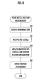
- Fig. 10 is a flow chart showing the flow of control for this first initial position measurement.
- the same step numbers are allocated to steps which consist of the same processing as in Fig. 6.
- the mobile telephone 1 receives ephemeris data from the center (a step S81).
- the mobile telephone 1 acquires this ephemeris data by communicating with the center by taking advantage of the mobile telephone communication unit 11.
- the mobile telephone 1 receives GPS signals which are emitted from the GPS satellites 3 with the GPS reception unit 12 (a step S41), and analyzes these GPS signals which it has received this time using the ephemeris data which it has acquired in the step S81, thereby acquiring position information which indicates its own position (a step S82).
- the mobile telephone 1 then stores its own position (a step S83) based upon this position information which it has thus acquired in the step S82, and then this processing ends.
- Fig. 11 is a flow chart showing the flow of control for this second initial position measurement.
- the same step numbers are allocated to steps which consist of the same processing as in Fig. 7.
- the mobile telephone 1 detects the digital camera 2 in cooperation with which it is possible to perform position measurement of its own position, and then starts to receive the GPS which are emitted from the GPS satellites 3 with the GPS reception unit 12 (steps S51 and S52). Furthermore, it transmits the GPS signals which it has received to the digital camera 2 (a step S54), and acquires the ephemeris data from this digital camera 2 (a step S91).
- the digital camera 2 transmits to the mobile telephone 1 the ephemeris data which it has acquired from the GPS signals which have been transmitted from the mobile telephone 1.
- the mobile telephone 1 analyzes the GPS signals which it has received this time using the ephemeris data acquired in the step S91, and acquires position information specifying its own position (a step S92).
- the mobile telephone 1 then stores (a step S93) the position information which it has acquired in the step S92, and then this processing ends.
- the mobile telephone 1 it is possible for the mobile telephone 1 to perform position measurement of its own position in cooperation with the digital camera 2.
- the digital camera 2 it is possible for the digital camera 2 to store a captured image in correspondence with the position in which this captured image was captured, and this can be helpful to the user for managing the capture images.
- this it would also be acceptable to arrange for this not to be performed periodically, but to be performed upon some actuation as a trigger, for example upon shutter actuation for photography.
Landscapes
- Engineering & Computer Science (AREA)
- Radar, Positioning & Navigation (AREA)
- Remote Sensing (AREA)
- Physics & Mathematics (AREA)
- General Physics & Mathematics (AREA)
- Computer Networks & Wireless Communication (AREA)
- Position Fixing By Use Of Radio Waves (AREA)
- Studio Devices (AREA)
- Mobile Radio Communication Systems (AREA)
Abstract
Description
- The present invention relates to a position measurement system which measures the current position by employing the GPS (Global Positioning System), and to a portable terminal which utilizes this position measurement system.
- In the prior art, devices have been implemented in practice which perform measurement of the current position by employing GPS. As is per se well known, this position measurement by GPS is a method by which a device (a receiver) receives GPS signals emitted from at least three satellites, and calculates its own position using these GPS signals. In concrete terms, each of the satellites emits, in its GPS signal, radio waves upon which are superimposed almanac data which is information specifying the orbit of the satellite, and ephemeris data which specifies detailed starting information for the satellite and the time instant that the signal was emitted. And the measurement of the position of the receiver is performed by a triangle intersection method, using the calculated distances from the receiver of the three satellites whose GPS signals have been received.
- Furthermore, as disclosed in
Japanese Laid-Open Patent Publication 2005-202397 Japanese Patent 3,671,795 - Furthermore, a mobile telephone endowed with GPS functionality has also been proposed (for example, in
Japanese Patent Publication 2005-528049 - However, such a mobile telephone endowed with GPS functionality which operates according to the MS-Assisted mode transmits the GPS signals which it has received from the satellites to the center via the mobile telephone network. Due to this, when the mobile telephone endowed with GPS functionality is positioned at a location in which it cannot connect to the mobile telephone network, i.e. is in a no-service area, it cannot transmit the GPS signals which it has received from the satellites to the center. Accordingly, with a prior art type of mobile telephone endowed with GPS functionality, there has been the problem that, when this mobile telephone is located in a no-service area, it is unable to measure its own position using GPS. Furthermore, since it is not possible for this mobile telephone endowed with GPS functionality to acquire its own position, accordingly, some other terminal which attempts to acquire its own position by short distance communication with this mobile telephone endowed with GPS functionality cannot acquire its own position either. In other words, with the structure disclosed in
Japanese Patent Publication 2005-528049 - The objective of the present invention is to provide a position measurement system which is capable of acquiring a position measurement result using GPS, even in a state in which when a portable terminal thereof whose method of measuring its own position is the MS-Assisted mode cannot connect to a center, and moreover with which this result of position measurement can be utilized by another portable terminal; and to provide said other portable terminal which is applied in this position measurement system.
- With the present invention, a first portable terminal receives a signal - a so called GPS signal - transmitted from a satellite via radio waves with a signal reception means, and transfers this signal which it has received to a second portable terminal, using a short distance wireless communication means such as BlueTooth (a trademark), ZigBee, or the like. This signal includes almanac data, which is information specifying the orbit of the satellite, and ephemeris data, which specifies the position of the satellite and the time instant of origination of the signal. Furthermore, when the second portable terminal receives this signal which has been transferred from the first portable terminal, it processes this signal which it has received with a position measurement means, and thereby measures the position of the first portable terminal. Due to the fact that, as described above, the communication between the first portable terminal and the second portable terminal is performed by short distance wireless communication, these two portable terminals are positioned at approximately the same location. Accordingly, by performing the processing described above, the second portable terminal is able to acquire its own position. Furthermore, a position measurement result notification means of the second portable terminal notifies the position of the first portable terminal, which it has acquired by the processing described above, to the first portable terminal, by taking advantage of the short distance wireless communication means. Accordingly, the first portable terminal is also able to acquire its own position.
- Furthermore, if the first portable terminal is a mobile telephone endowed with GPS functionality, which is equipped with a position measurement function with GPS which operates by GPS in the MS-Assisted mode, then, even when this mobile telephone is located in a no-service area in which it cannot connect to any mobile telephone network, it is able to obtain a position measurement result by GPS, if such a second portable terminal is present within the communication area for short distance wireless communication. Moreover, the second portable terminal is able to acquire its own position, irrespective of whether or not the mobile telephone, which is the first portable terminal, is located in a no-service area.
- Yet further, if the first portable terminal is a mobile telephone endowed with GPS functionality, which is equipped with a position measurement function with GPS which operates by GPS in the MS-Based mode, then it will be acceptable to provide, to this first portable terminal, a position measurement result notification means by which the first portable terminal, which has measured its own position, notifies this position to the second portable terminal.
- Even further, the portable terminal according to this invention is the second portable terminal in the above described position measurement system.
-
- Fig. 1 is a schematic figure showing a position measurement system which is an embodiment of the present invention;
- Fig. 2 is a figure showing the principal structure of a mobile telephone which is employed in this position measurement system according to an embodiment of the present invention;
- Fig. 3 is a figure showing the principal structure of a digital camera which is employed in this position measurement system according to an embodiment of the present invention;
- Fig. 4 is a flow chart showing the operation of this mobile telephone of the position measurement system of this embodiment in a third mode thereof;
- Fig. 5 is a flow chart showing the operation of this digital camera of the position measurement system of this embodiment in a B mode thereof;
- Fig. 6 is a flow chart showing a first initial position measurement by this mobile telephone of the position measurement system of this embodiment;
- Fig. 7 is a flow chart showing a second initial position measurement by this mobile telephone of the position measurement system of this embodiment;
- Fig. 8 is a flow chart showing the operation of a mobile telephone of a position measurement system of another embodiment in a third mode thereof;
- Fig. 9 is a flow chart showing the operation of a digital camera of the position measurement system of this other embodiment in a B mode thereof;
- Fig. 10 is a flow chart showing a first initial position measurement by this mobile telephone of the position measurement system of this other embodiment; and
- Fig. 11 is a flow chart showing a second initial position measurement by this mobile telephone of the position measurement system of this other embodiment.
- Fig. 1 is a schematic figure showing a position measurement system which is an embodiment of the present invention. This position measurement system according to the present invention comprises a
mobile telephone 1 and adigital camera 2. Themobile telephone 1 corresponds to the "first portable terminal" of the Claims, while thedigital camera 2 corresponds to the "second portable terminal" of the Claims. Furthermore, thereference symbols 3 shown in Fig. 1 denote GPS satellites. In Fig. 1, threeGPS satellites 3 are shown. Themobile telephone 1 is a so called mobile telephone endowed with GPS functionality, which comprises a GPS reception unit which receives GPS signals transmitted from theseGPS satellites 3. These GPS signals include almanac data, which is information specifying the orbit of the satellite, and ephemeris data, which specifies the position of the satellite and the time instant of origination of the signal. Furthermore, themobile telephone 1 and thedigital camera 2 are adapted so as to be able to perform mutual communication by short distance wireless communication, for example by Bluetooth (a trademark) or ZigBee or the like. In this embodiment, themobile telephone 1 is a mobile telephone endowed with GPS functionality which operates in the MS-Assisted mode. - It should be understood that it would also be acceptable to arrange for the short distance wireless communication between the
mobile telephone 1 and thedigital camera 2 to be performed by infrared communication using Ir-DA. - Fig. 2 is a figure showing the principal structure of this mobile telephone employed in the position measurement system according to this embodiment of the present invention. This
mobile telephone 1 comprises acontrol unit 10, a mobiletelephone communication unit 11, aGPS reception unit 12, a short distancewireless communication unit 13, anaudio processing unit 14, anactuation unit 15, and adisplay unit 16. Thecontrol unit 10 controls the operation of the main sections of the mobile telephone. The mobiletelephone communication unit 11 communicates with a terminal, such as another mobile telephone or the like, via a mobile telephone network not shown in the figures. TheGPS reception unit 12 receives the GPS signals emitted by theGPS satellites 3. The short distancewireless communication unit 13 performs short distance wireless communication. Theaudio processing unit 14 performs processing of input and output audio during audio communication with another terminal using the mobiletelephone communication unit 11. Theactuation unit 15 receives input actuation for the device as a whole. And thedisplay unit 16 displays the operational state of the device as a whole, and so on. - In hardware terms, this
mobile telephone 1 consists of a per se known mobile telephone endowed with GPS functionality which operates in the MS-Assisted mode, but with the short distancewireless communication unit 13 appended. This short distancewireless communication unit 13 is provided in order to perform short distance wireless communication with thedigital camera 2. Furthermore, thismobile telephone 1 transmits the GPS signals which it has received with theGPS reception unit 12 to a center not shown in the figure, and acquires its own position by receiving the results of position measurement from the center. Themobile telephone 1 performs communication with the center by using the mobiletelephone communication unit 11. Moreover, themobile telephone 1 transmits the GPS signals which it has received from theGPS satellite 3 with theGPS reception unit 12 to thedigital camera 2, using the short distancewireless communication unit 13. Yet further, using the short distancewireless communication unit 13, themobile telephone 1 receives position measurement results which have been transmitted from thedigital camera 2. - Fig. 3 is a figure showing the principal structure of this
digital camera 2, which is an embodiment of the present invention. Thisdigital camera 2 comprises acontrol unit 20, animage capturing unit 21, animage processing unit 22, a capturedimage storage unit 23, adisplay unit 24, anactuation unit 25, a short distancewireless communication unit 26, and aGPS processing unit 27. Thecontrol unit 20 controls the overall operation of thisdigital camera 2. Theimage capturing unit 21 captures an image. Theimage processing unit 22 processes an image which has been captured by theimage capturing unit 21. The capturedimage storage unit 23 stores a captured image. Thedisplay unit 24 displays a viewfinder image or the like. On theactuation unit 25, input actuation for the main body of the device is performed. The short distancewireless communication unit 26 performs short distance wireless communication. And theGPS processing unit 27 performs position measurement by processing the almanac data and ephemeris data contained in the GPS signals. - In hardware terms, this
digital camera 2 consists of a per se known type of digital camera, but with the short distancewireless communication unit 26 and theGPS processing unit 27 appended. This short distancewireless communication unit 26 is a structure for performing short distance wireless communication with themobile telephone 1. Furthermore, theGPS processing unit 27 is a structure which processes the GPS signals which are acquired from themobile telephone 1, and which performs position measurement processing for measuring the position of thismobile telephone 1. Thedigital camera 2 notifies the position which it has obtained by this position measurement processing (the position of the mobile telephone 1) to themobile telephone 1. This notification is also performed by short distance wireless communication. Since, as described above, themobile telephone 1 and thedigital camera 2 communicate by short distance wireless communication, accordingly the position of themobile telephone 1 and the position of thedigital camera 2 are approximately the same position. Thus, thedigital camera 2 also takes advantage of the position of themobile telephone 1, which it has obtained by the above described position measurement processing, as being its own position. In concrete terms, thedigital camera 2 is endowed with a function of storing a captured image, and the position at which this captured image was captured (hereinafter this will be termed the "image capture position") in mutual correspondence in the capturedimage storage unit 23. This image capture position is the position of themobile telephone 1 which has been acquired by theGPS processing unit 27 during the position measurement processing. - It should be understood that this
mobile telephone 1 is also able to transmit the GPS signals which it has received to a center, and to obtain a position measurement result from the center. Furthermore, thisdigital camera 2 is also able to request themobile telephone 1 to transfer the position measurement result which it has acquired from the center (i.e. the position of this mobile telephone 1), and thus to acquire this position measurement result. The communication between themobile telephone 1 and thedigital camera 2 at this time is, again, performed by short distance wireless communication. - In the following, the operation of this position measurement system according to an embodiment of the present invention will be explained.
- The
mobile telephone 1 is able to operate in a first mode in which the GPS function is OFF, in a second mode in which it performs position measurement of its own position in the MS-Assisted mode, and in a third mode in which it performs position measurement of its own position in cooperation with thedigital camera 2. With regard to the first mode and the second mode, since they are the same as in the case of a per se known mobile telephone endowed with GPS functionality which operates in the MS-Assisted mode, explanation thereof will herein be omitted. The changing over between the first mode, the second mode, and the third mode is performed by key actuation upon theactuation unit 15. On the other hand, thedigital camera 2 is able to operate in an A mode in which, in cooperation with themobile telephone 1, the GPS function of performing position measurement of the position of thismobile telephone 1 is OFF, and in a B mode in which, in cooperation with themobile telephone 1, the GPS function of performing position measurement of the position of thismobile telephone 1 is ON. The changing over between the A mode and the B mode is performed by key actuation upon theactuation unit 25. Furthermore, with regard to capturing of an image by theimage capturing unit 21 of thedigital camera 2, this is performed by actuation of the shutter button, irrespective of whether thedigital camera 2 is in the A mode or in the B mode. With regard to the A mode, since it is the same as in the case of a per se known digital camera, explanation thereof will herein be omitted. - Fig. 4 is a flow chart showing the operation of this
mobile telephone 1 of the position measurement system according to this embodiment in its third mode, and Fig. 5 is a flow chart showing the operation of thisdigital camera 2 of the position measurement system according to this embodiment in its B mode. When actuation of themobile telephone 1 to change it over to its third mode is performed upon theactuation unit 15, then the processing shown in Fig. 4 is started. And when, during the execution of the processing shown in Fig. 4, actuation of themobile telephone 1 to change it over to some other mode is performed upon theactuation unit 15, then the processing shown in Fig. 4 is stopped, and operation in the mode to which changing over has been performed is started. Furthermore, when actuation of thedigital camera 2 to change it over to its B mode is performed upon theactuation unit 25, then the processing shown in Fig. 5 is started. And, when during the execution of the processing shown in Fig. 5, actuation of thedigital camera 2 to change it over to some other mode is performed upon theactuation unit 25, then the processing shown in Fig. 5 is stopped, and operation in the mode to which changing over has been performed is started. - When its operation in its third mode starts, the
mobile telephone 1 first, initially, makes a decision whether or not communication with the center is possible (a step S1). This communication with the center is performed via the mobiletelephone communication unit 11. Accordingly, themobile telephone 1 is not able to communication with the center, when it is in a location in which it cannot connect to the mobile telephone network (not shown in the figures), i.e. when it is in a so-called no-service area. When themobile telephone 1 decides in this step S1 that it can communicate with the center, then it acquires its own position by taking advantage of the center, and thus performs a first initial position measurement (a step S2). On the other hand, if in the step S1 it is decided that communication with the center is not possible, then themobile telephone 1 acquires its own position by taking advantage of thedigital camera 2, and thus performs a second initial position measurement (a step S3). The processing performed in the steps S2 and S3 is processing for themobile telephone 1, along with acquiring its own position, also to acquire valid almanac data, which is orbital information for theGPS satellites 3. The processing performed in these steps S2 and S3 will be described in detail hereinafter. - When the first initial position measurement in the step S2 is completed, then, via the short distance
wireless communication unit 13, themobile telephone 1 looks for adigital camera 2 of a type in cooperation with which position measurement of its own position can be performed (a step S4). Here, themobile telephone 1 looks for adigital camera 2 in cooperation with which position measurement of its own position can be performed, which is positioned within the communication area of the short distancewireless communication unit 13. In other words, themobile telephone 1 looks for adigital camera 2 which can perform short distance wireless communication with the short distancewireless communication unit 13. - It should be understood that, in the processing for second initial position measurement, the
mobile telephone 1 looks for adigital camera 2 of a type in cooperation with which position measurement of its own position can be performed. Accordingly, if themobile telephone 1 has performed the second initial position measurement of the step S3, then the processing of this step S4 is not executed. - Furthermore, if the
mobile telephone 1 cannot detect anydigital camera 2 of a type in cooperation with which position measurement of its own position can be performed, then the processing of the step S4 is repeated at a predetermined time interval which is specified in advance. - When the processing for the second initial position measurement in the step S3 has been completed, or when a
digital camera 2 in cooperation with which position measurement of its own position can be performed is detected in the step S4, then themobile telephone 1 starts processing to receive the GPS signals which are being emitted from theGPS satellites 3 repeatedly, each time a first time period which is determined in advance elapses (steps S5 and S6). Themobile telephone 1 receives the GPS signals via theGPS reception unit 12. When themobile telephone 1 receives the GPS signals in the step S6, it stores these GPS signals which it has received (a step S7). The GPS signals are stored in a memory provided to thecontrol unit 10, not shown in the figures. Furthermore when, while themobile telephone 1 is performing the processing of the steps S5 through S7, a transmission request for the GPS signals is received from thedigital camera 2 by the short distancewireless communication unit 13, then it transmits the newest GPS signals which it has stored in the memory to thedigital camera 2 which has transmitted this request for transmission thereof (steps S8 and S9). This receipt of a request for transmission of the GPS signals, and the transmission of the GPS signals, are both performed via the short distancewireless communication unit 13. Furthermore, when themobile telephone 1 receives the result of position measurement of its own position which has been transmitted from thedigital camera 2 via the short distancewireless communication unit 13, then it updates its own position in storage (steps S10 and S11). The processing performed in these steps S10 and S11 may also be performed while the processing of the steps S5 through S7 is being executed. Moreover, if a state comes to hold in which themobile telephone 1 is not able to perform short distance communication with thedigital camera 2 via the short distance wireless communication unit 13 (a step S12), then the flow of control returns to the step S4 and the processing described above is repeated. - It should be understood that, while this
mobile telephone 1 is operating in this third mode as well, it is still capable of communicating with other terminals upon the mobile telephone network, via the mobiletelephone communication unit 11. Moreover, if actuation is performed via theactuation unit 15 to change themobile telephone 1 over to some other mode, or if actuation is performed to turn OFF the power supply to themobile telephone 1 or the like, then the processing shown in this Fig. 4 terminates, and operation in the mode to which changeover has been performed is started. - Next, the operation of the
digital camera 2 in its B mode will be explained with reference to Fig. 5. When thedigital camera 2 starts its operation in its B mode, it searches, using the short distancewireless communication unit 26, for amobile telephone 1 of a type in cooperation with which position measurement of its own position can be performed (a step S21). Thedigital camera 2 acquires the position of themobile telephone 1, which it considers as being substantially its own position. When thedigital camera 2 is able to establish short distance wireless communication via the short distancewireless communication unit 26 with themobile telephone 1, then it decides that it has detected amobile telephone 1 of a type in cooperation with which it can perform position measurement of its own position. To put it in another manner, when themobile telephone 1 described above is able to establish short distance wireless communication via the short distancewireless communication unit 13 with thedigital camera 2, then it decides that it has detected adigital camera 2 of a type in cooperation with which it can perform position measurement of its own position. - It should be understood that, if in the step S21 the
digital camera 2 is not able to detect amobile telephone 1 in cooperation with which it can perform position measurement of its own position, then the processing of the step S21 is repeated at predetermined time intervals which are determined in advance. Moreover, during this processing, thedigital camera 2 is also able to capture an image with theimage capturing unit 21, to process this captured image with the capturedimage processing unit 22, and to store this captured image in the capturedimage storage unit 23. - When in the step S21 the
digital camera 2 detects amobile telephone 1 in cooperation with which it can perform position measurement of its own position, then via the short distancewireless communication unit 26 it repeatedly requests themobile telephone 1 to transmit GPS signals, at intervals of a second time period which is determined in advance (steps S22 and S23). This second time period may be set to be the same time period as the first time period described above, or also may be a different time period. However, it is desirable for this second time period to be set to be greater than or equal to the first time period, in order to prevent thedigital camera 2 from performing useless position measurement processing (i.e. position measurement processing upon the same GPS signals). Themobile telephone 1 receives the request for transmission of GPS signals which has been outputted by thedigital camera 2 in this step S23, in the step S8 described above. - Furthermore when, while the
digital camera 2 is executing the processing of the steps S22 and S23, it receives via the short distancewireless communication unit 26 the GPS signals which have been transmitted from the mobile telephone 1 (a step S24), then it processes these GPS signals which it has received with theGPS processing unit 27, and performs position measurement processing for calculating the position of the mobile telephone 1 (a step S25). Since the processing in this step S25 is position measurement processing according to a per se known triangle intersection method using the GPS signals, accordingly the details thereof will herein be omitted. When thedigital camera 2 has calculated the position of themobile telephone 1 in the step S25, it transmits the position which it has calculated at this time to themobile telephone 1 as the result of position measurement (a step S26). Furthermore, it stores the position which it has calculated at this time in the memory of thecontrol unit 20 as its own position (a step S27). - Furthermore, when the shutter button (not shown in the figures) which is provided to the
actuation unit 25 is actuated (a step S28), then thedigital camera 2 inputs an image which is captured by theimage capturing unit 21 at this time point to the image processing unit 22 (a step S29). And thedigital camera 2 establishes a correspondence between this captured image which it has inputted in the step S29 and its own most recent position which is stored at this time point (a step S30), and stores this in the captured image storage unit 23 (a step S31). Furthermore, if a state comes to hold in which thedigital camera 2 is not able to perform short distance wireless communication with themobile telephone 1 via the short distance wireless communication unit 26 (a step S32), then the flow of control returns to the step S21 and the processing described above is repeated. - It should be understood that if actuation is performed via the
actuation unit 25 to change thedigital camera 2 over to some other mode, or if actuation is performed to turn OFF the power supply to thedigital camera 2 or the like, then the processing shown in this Fig. 5 terminates, and operation in the mode to which changeover has been performed is started. - Next, the operation performed by the
mobile telephone 1 for the first initial position measurement in the step S2 will be explained in detail. Fig. 6 is a flow chart showing the flow of control for this first initial position measurement. Themobile telephone 1 receives GPS signals which are emitted from theGPS satellites 3 with the GPS reception unit 12 (a step S41), and transmits these GPS signals which it has received to the center (a step S42). In the step S42, themobile telephone 1 transmits the GPS signals which it has received this time to the center using the mobiletelephone communication unit 11. And, after the GPS signals have been transmitted to the center in the step S42, when themobile telephone 1 receives from the center with the mobiletelephone communication unit 11 the result of position measurement which indicates its own position (a step S43), then it stores its own position based upon this position measurement result which it has thus received (a step S44), and then this processing ends. - It should be understood that, in this first initial position measurement, if the almanac data and ephemeris data which are stored in the main body of the
mobile telephone 1 require to be updated, then themobile telephone 1 updates this data. Furthermore, according to requirements, themobile telephone 1 may transmit the almanac data and ephemeris data which are stored in its own main body to thedigital camera 2, by utilizing the short distancewireless communication unit 13. - Next, the operation performed by the
mobile telephone 1 for the second initial position measurement in the step S3 will be explained in detail. Fig. 7 is a flow chart showing the flow of control for this second initial position measurement. Themobile telephone 1 searches for adigital camera 2 of a type in cooperation with which it can perform position measurement of its own position (a step S51). This processing in the step S51 is the same as the processing in the step S4 described above. When in the step S51 themobile telephone 1 detects adigital camera 2 of a type in cooperation with which it can perform position measurement of its own position, then it starts to receive the GPS signals which are being emitted by theGPS satellites 3 with the GPS reception unit 12 (a step S52). In this step S52, the GPS signals are received at a predetermined time intervals determined in advance. When themobile telephone 1 receives a request for transmission of these GPS signals from the digital camera 2 (a step S53), it transmits the newest GPS signals to the digital camera 2 (a step S54). In this step S54, themobile telephone 1 transmits the GPS signals to themobile telephone 2 by utilizing the short distancewireless communication unit 13. And when, after having transmitted the GPS signals in the step S54, themobile telephone 1 receives from thedigital camera 2, via the short distancewireless communication unit 13, the result of position measurement which indicates its own current position (a step S55), then it stores its own position based upon the position measurement result which it has thus received (a step S56), and then this processing terminates. - In this manner, with the position measurement system of this embodiment, it is possible for the
mobile telephone 1 to perform position measurement of its own position in cooperation with thedigital camera 2, even in a state in which communication with the center is not possible. Moreover, it is possible for thedigital camera 2 to store a captured image in correspondence with the position in which this captured image was captured, and this can be helpful to the user for managing the capture images. Furthermore, as far as the timing of communication and position measurement and analysis is concerned, it would also be acceptable to arrange for this not to be performed periodically, but to be performed upon some actuation as a trigger, for example upon shutter actuation for photography. - Next, another embodiment of the present invention will be explained. This embodiment differs from the embodiment described above in the aspect that the
mobile telephone 1 is of an MS-Based type. In other words, thismobile telephone 1 is able to perform position measurement of its own position from GPS signals which it has received, provided that it is able to acquire adequate ephemeris data. Fig. 8 is a flow chart showing the operation of thismobile telephone 1 of the position measurement system of this other embodiment in its third mode, and Fig. 9 is a flow chart showing the operation of adigital camera 2 of the position measurement system of this other embodiment in its B mode. - It should be understood that since, just as in the case of the embodiment described above, the operation of this
mobile telephone 1 in its first mode and in its second mode are the same as in the case of a per se known mobile telephone, accordingly explanation thereof will herein be omitted; and similarly since, just as in the case of the embodiment described above, the operation of thisdigital camera 2 in its A mode is the same as in the case of a per se known digital camera, accordingly explanation thereof will herein be omitted. Furthermore, in Fig. 8, the same step numbers are allocated to steps which consist of the same processing as in Fig. 4; and, similarly, in Fig. 9, the same step numbers are allocated to steps which consist of the same processing as in Fig. 5. - When actuation of the
mobile telephone 1 to change it over to its third mode is performed upon theactuation unit 15, then the processing shown in Fig. 8 is started. And when, during the execution of the processing shown in Fig. 8, actuation of themobile telephone 1 to change it over to some other mode is performed upon theactuation unit 15, then the processing shown in Fig. 8 is stopped, and operation in the mode to which changing over has been performed is started. Furthermore, when actuation of thedigital camera 2 to change it over to its B mode is performed upon theactuation unit 25, then the processing shown in Fig. 9 is started. And, when during the execution of the processing shown in Fig. 9, actuation of thedigital camera 2 to change it over to some other mode is performed upon theactuation unit 25, then the processing shown in Fig. 9 is stopped, and operation in the mode to which changing over has been performed is started. - When its operation in its third mode starts, the
mobile telephone 1 first, initially, performs the processing described in the steps S1 through S4 shown in Fig. 4, and thereafter starts processing to receive the GPS signals emitted by theGPS satellites 3, every time a first time period which has been determined in advance elapses (steps S5 and S6). When themobile telephone 1 receives the GPS signals in the step S6, it analyzes these received GPS signals, and acquires position information specifying its own position (a step S61). And themobile telephone 1 stores this information specifying its own position, which it has thus acquired, in a memory provided to thecontrol unit 10, not shown in the figures (a step S62). Moreover when, during the execution of the processing in these steps S5, S6, S61, and S62, themobile telephone 1 receives via the short distance wireless communication unit 13 a transmission request for the position information from thedigital camera 2, it transmits the most recent position information stored in the memory to thedigital camera 2 from which this transmission request has been transmitted (steps S63 and S64). This reception of the position information transmission request and transmission of the position information are performed via the short distancewireless communication unit 13. Furthermore, the above described flow of control returns to the step S4 and repeats the processing described above, until a state comes to hold in which themobile telephone 1 is not able to perform short distance communication with thedigital camera 2 via the short distancewireless communication unit 13. - It should be understood that, with the
mobile telephone 1 of this embodiment, the processing described in the steps S10 and S11 shown in Fig. 4 is not performed. Furthermore, just as in the case of the first embodiment described above, when themobile telephone 1 of this embodiment is operating in its third mode, it is also able to perform communication with other terminals upon the mobile telephone network via the mobiletelephone communication unit 11. Moreover, if actuation is performed via theactuation unit 15 to change themobile telephone 1 over to some other mode, or if actuation is performed to turn OFF the power supply to themobile telephone 1 or the like, then the processing shown in this Fig. 8 terminates, and operation in the mode to which changeover has been performed is started. - Next, the operation of the
digital camera 2 in its B mode will be explained with reference to Fig. 9. When thedigital camera 2 starts its operation in its B mode, it performs the processing described in the step S21 for the case of the first embodiment described above. Similarly, thisdigital camera 2 of this embodiment also acquires the position of themobile telephone 1, which it considers as being substantially its own position. When thedigital camera 2 detects in this step S21 amobile telephone 1 of a type in cooperation with which it can perform position measurement of its own position, then via the short distancewireless communication unit 26 it repeatedly requests themobile telephone 1 to transmit position information, at intervals of a second time period which is determined in advance (steps S22 and S71). This second time period may be set to be the same time period as the first time period described above, or also may be a different time period. Themobile telephone 1 receives the request for transmission of position information which has been outputted by thedigital camera 2 in this step S71, in the step S63 described above. - Furthermore when, while the
digital camera 2 is executing the processing of the steps S22 and S71, it receives via the short distancewireless communication unit 26 the position information which has been transmitted from the mobile telephone 1 (a step S72), then it stores this position information which it has received in the memory of the control unit 20 (a step S73). In other words, thedigital camera 2 stores the position specified by the position information which has been transmitted from themobile telephone 1, as its own position. - Furthermore, when the shutter button (not shown in the figures) which is provided to the
actuation unit 25 is actuated (a step S28), then thedigital camera 2 performs the same processing as described above in the steps S29 through S31 with respect to the first embodiment, and, if a state comes to hold in which thedigital camera 2 is not able to perform short distance wireless communication with themobile telephone 1 via the short distance wireless communication unit 26 (a step S32), then the flow of control returns to the step S21 and the processing described above is repeated. - It should be understood that if actuation is performed via the
actuation unit 25 to change thedigital camera 2 over to some other mode, or if actuation is performed to turn OFF the power supply to thedigital camera 2 or the like, then the processing shown in this Fig. 9 terminates, and operation in the mode to which changeover has been performed is started. - Next, the operation performed by the
mobile telephone 1 for the first initial position measurement in the step S2 will be explained in detail. Fig. 10 is a flow chart showing the flow of control for this first initial position measurement. In Fig. 10, the same step numbers are allocated to steps which consist of the same processing as in Fig. 6. Themobile telephone 1 receives ephemeris data from the center (a step S81). In this step S81, themobile telephone 1 acquires this ephemeris data by communicating with the center by taking advantage of the mobiletelephone communication unit 11. And themobile telephone 1 receives GPS signals which are emitted from theGPS satellites 3 with the GPS reception unit 12 (a step S41), and analyzes these GPS signals which it has received this time using the ephemeris data which it has acquired in the step S81, thereby acquiring position information which indicates its own position (a step S82). Themobile telephone 1 then stores its own position (a step S83) based upon this position information which it has thus acquired in the step S82, and then this processing ends. - Next, the operation performed by the
mobile telephone 1 for the second initial position measurement in the step S3 will be explained in detail. Fig. 11 is a flow chart showing the flow of control for this second initial position measurement. In Fig. 11, the same step numbers are allocated to steps which consist of the same processing as in Fig. 7. Via the short distancewireless communication unit 13, themobile telephone 1 detects thedigital camera 2 in cooperation with which it is possible to perform position measurement of its own position, and then starts to receive the GPS which are emitted from theGPS satellites 3 with the GPS reception unit 12 (steps S51 and S52). Furthermore, it transmits the GPS signals which it has received to the digital camera 2 (a step S54), and acquires the ephemeris data from this digital camera 2 (a step S91). And thedigital camera 2 transmits to themobile telephone 1 the ephemeris data which it has acquired from the GPS signals which have been transmitted from themobile telephone 1. Themobile telephone 1 then analyzes the GPS signals which it has received this time using the ephemeris data acquired in the step S91, and acquires position information specifying its own position (a step S92). Themobile telephone 1 then stores (a step S93) the position information which it has acquired in the step S92, and then this processing ends. - In this manner, with the position measurement system of this embodiment as well, it is possible for the
mobile telephone 1 to perform position measurement of its own position in cooperation with thedigital camera 2. Moreover, it is possible for thedigital camera 2 to store a captured image in correspondence with the position in which this captured image was captured, and this can be helpful to the user for managing the capture images. Furthermore, as far as the timing of communication and position measurement and analysis is concerned, it would also be acceptable to arrange for this not to be performed periodically, but to be performed upon some actuation as a trigger, for example upon shutter actuation for photography. - It should be understood that, in the above described explanation of embodiments of the present invention, all of the features are shown by way of example, and should not be considered as being limitative of the present invention. The scope of the present invention is not to be defined by any of the features of the embodiment described above, but only by the scope of the appended Claims. Moreover, equivalents to elements in the Claims, and variations within their legitimate and proper scope, are also to be considered as being included within the range of the present invention.
Claims (7)
- A position measurement system comprising first and second portable terminals (1, 2) which comprise short distance wireless communication means (13, 26) for performing short distance wireless communication, and which performs position measurement using a signal transmitted from a satellite via radio waves, wherein:said first portable terminal (1) comprises:a signal reception means (12) which receives a signal transmitted from a satellite via radio waves; anda signal transfer means (10) which transfers said signal received by said signal reception means (12) to said second portable terminal (2) using said short distance wireless communication means (13);and said second portable terminal (2) comprises:a position measurement means (27) which, when said signal which has been transmitted by said signal transfer means (10) of said first portable terminal (1) has been received by said short distance wireless communication means (26), measures the position of said first portable terminal (1) based upon said received signal; anda position measurement result notification means (20) which notifies the position of said first portable terminal (1) which has been measured by said position measurement means (27) to said first portable terminal (1), using said short distance wireless communication means (26).
- A position measurement system according to Claim 1, wherein said first portable terminal (1) further comprises a mobile telephone communication means (11) which performs communication with other terminals via a mobile telephone network.
- A position measurement system according to Claim 2, wherein said second portable terminal (2) further comprises:an image capture means (21) which captures an image of an image capture area; and
a captured image storage means (23) which stores a captured image of an image capture area which has been captured by said image capture means (21), and the position of said first portable terminal (1) which has been measured by said position measurement means (27) directly before the capturing of said captured image, in mutual correspondence. - A position measurement system comprising first and second portable terminals (1, 2) which comprise short distance wireless communication means (13, 26) for performing short distance wireless communication, and which performs position measurement using a signal transmitted from a satellite via radio waves, wherein:said first portable terminal (1) comprises:a signal reception means (12) which receives a signal transmitted from a satellite via radio waves;a position measurement means (10) which measures its own position, based upon said signal received by said signal reception means (12); anda position measurement result notification means (10) which notifies its own position, which has been measured by said position measurement means (10), to said second portable terminal (2), using said short distance wireless communication means (13);and said second portable terminal (2) comprises:a storage means (10) which stores the position of said first portable terminal (1) which has been notified by said position measurement result notification means (10) of said first portable terminal (1), via said short distance wireless communication means (26);an image capture means (21) which captures an image of an image capture area; anda captured image storage means (23) which stores a captured image of an image capture area which has been captured by said image capture means (21), and the position of said first portable terminal (1) which has been stored by said storage means (10), in mutual correspondence.
- A position measurement system according to Claim 4, wherein said first portable terminal (1) further comprises a mobile telephone communication means (11) which performs communication with other terminals via a mobile telephone network.
- A portable terminal (2), comprising:a short distance wireless communication means (26) which performs short distance wireless communication;a signal acquisition means (20) which acquires, by using said short distance wireless communication means (26), a signal from another portable terminal (1) which comprises a signal reception means (12) which receives a signal transmitted from a satellite via radio waves;a position measurement means (27) which, based upon said signal which has been acquired by said signal acquisition means (20), measures the position of said other portable terminal (1) from which said signal has been transmitted; anda position measurement result notification means (20) which notifies, to said other portable terminal (1), using said short distance wireless communication means (26), the position of said other portable terminal (1) as measured by said position measurement means (27).
- A portable terminal (2) according to Claim 6, further comprising:an image capture means (21) which captures an image of an image capture area; anda captured image storage means (23) which stores a captured image of an image capture area which has been captured by said image capture means (21), and the position of said other portable terminal (1) which has been measured by said position measurement means (27) directly previously, in mutual correspondence.
Applications Claiming Priority (1)
| Application Number | Priority Date | Filing Date | Title |
|---|---|---|---|
| JP2006229472A JP4254822B2 (en) | 2006-08-25 | 2006-08-25 | Positioning system and mobile terminal |
Publications (1)
| Publication Number | Publication Date |
|---|---|
| EP1892539A1 true EP1892539A1 (en) | 2008-02-27 |
Family
ID=38695532
Family Applications (1)
| Application Number | Title | Priority Date | Filing Date |
|---|---|---|---|
| EP07016385A Withdrawn EP1892539A1 (en) | 2006-08-25 | 2007-08-21 | Position measurement system and portable terminal |
Country Status (4)
| Country | Link |
|---|---|
| US (1) | US7890121B2 (en) |
| EP (1) | EP1892539A1 (en) |
| JP (1) | JP4254822B2 (en) |
| CN (1) | CN101131428A (en) |
Cited By (1)
| Publication number | Priority date | Publication date | Assignee | Title |
|---|---|---|---|---|
| US20140097982A1 (en) * | 2012-10-10 | 2014-04-10 | Honeywell International Inc. | Transmitting positions of devices |
Families Citing this family (13)
| Publication number | Priority date | Publication date | Assignee | Title |
|---|---|---|---|---|
| KR101320143B1 (en) * | 2009-05-04 | 2013-10-23 | 주식회사 팬택 | Mobile terminal for location management using meltimedia data and method thereof |
| US20100277365A1 (en) * | 2009-05-04 | 2010-11-04 | Pantech Co., Ltd. | Mobile terminal to provide location management using multimedia data and method thereof |
| US8644854B2 (en) * | 2009-12-03 | 2014-02-04 | Osocad Remote Limited Liability Company | System and method for processing enhanced data exchanged with an enhanced mobile station via a wireless connection |
| GB201107849D0 (en) * | 2011-05-11 | 2011-06-22 | Cambridge Silicon Radio Ltd | Cooperative positioning |
| KR20130064545A (en) | 2011-12-08 | 2013-06-18 | 현대자동차주식회사 | Apparatus for processing position information and method for precessing position information |
| JP6062239B2 (en) * | 2012-12-27 | 2017-01-18 | 株式会社ザクティ | Electronics |
| JP6155953B2 (en) * | 2013-08-13 | 2017-07-05 | カシオ計算機株式会社 | Information communication apparatus, information communication system, information communication method, and program |
| JP6256430B2 (en) * | 2015-08-17 | 2018-01-10 | コニカミノルタ株式会社 | Content providing server, content providing method, and computer program |
| JP2017062165A (en) * | 2015-09-24 | 2017-03-30 | カシオ計算機株式会社 | Positioning device, positioning control method and program |
| JP2017129590A (en) * | 2017-02-15 | 2017-07-27 | カシオ計算機株式会社 | Information communication apparatus, information communication system, information communication method, and program |
| JP2019060624A (en) | 2017-09-25 | 2019-04-18 | カシオ計算機株式会社 | Satellite radio wave receiver, electronic timepiece, positioning control method and program |
| JP7363479B2 (en) | 2017-11-06 | 2023-10-18 | 株式会社ニコン | Programs and electronics |
| JP6849123B2 (en) * | 2020-03-25 | 2021-03-24 | カシオ計算機株式会社 | Positioning device, positioning control method and program |
Citations (8)
| Publication number | Priority date | Publication date | Assignee | Title |
|---|---|---|---|---|
| US20010048746A1 (en) * | 2000-05-25 | 2001-12-06 | U. S. Philips Corporation | Method of estimating the location of a device |
| US20020085111A1 (en) * | 2001-01-03 | 2002-07-04 | Arie Heiman | Method and apparatus for providing travel information |
| US20020145560A1 (en) * | 2001-04-05 | 2002-10-10 | Sirf Technology, Inc. | Gps-based positioning system for mobile gps terminals |
| US20030073447A1 (en) * | 2001-09-06 | 2003-04-17 | Tadao Ogaki | Positioning information transmitting device and positioning information transmitting/receiving system |
| US6768450B1 (en) * | 2002-11-07 | 2004-07-27 | Garmin Ltd. | System and method for wirelessly linking a GPS device and a portable electronic device |
| US20050186965A1 (en) * | 2002-05-27 | 2005-08-25 | John Pagonis | Method of enabling a wireless information device to access location data |
| WO2006043123A1 (en) * | 2004-10-21 | 2006-04-27 | Nokia Corporation | Satellite based positioning |
| WO2006099998A1 (en) * | 2005-03-23 | 2006-09-28 | Sony Ericsson Mobile Communications Ab | Global positioning system (gps) accessories, hosts and methods that use radio frequency transmission of raw gps data |
Family Cites Families (7)
| Publication number | Priority date | Publication date | Assignee | Title |
|---|---|---|---|---|
| JP3671795B2 (en) | 2000-01-26 | 2005-07-13 | 松下電工株式会社 | Reporting system |
| US6959207B2 (en) * | 2000-12-22 | 2005-10-25 | Nokia Corporation | Mobile emotional notification application |
| JP2003209886A (en) | 2002-01-16 | 2003-07-25 | Sony Corp | Mobile terminal, position information providing system, and imaging system |
| JP2004032325A (en) | 2002-06-25 | 2004-01-29 | Seiko Epson Corp | Dynamic function extending system, mobile terminal, service providing terminal, user authentication terminal, program for terminal, and dynamic function extending method |
| KR100493235B1 (en) * | 2002-12-02 | 2005-06-02 | 한국전자통신연구원 | communication device having a function for searching access point of wireless local area network and method thereof |
| US7450163B2 (en) * | 2004-11-29 | 2008-11-11 | Rothschild Trust Holdings, Llc | Device and method for embedding and retrieving information in digital images |
| JP2005202397A (en) | 2005-01-11 | 2005-07-28 | Hitachi Ltd | Terminal device |
-
2006
- 2006-08-25 JP JP2006229472A patent/JP4254822B2/en not_active Expired - Fee Related
-
2007
- 2007-08-21 EP EP07016385A patent/EP1892539A1/en not_active Withdrawn
- 2007-08-22 US US11/843,062 patent/US7890121B2/en not_active Expired - Fee Related
- 2007-08-24 CN CNA2007101468201A patent/CN101131428A/en active Pending
Patent Citations (8)
| Publication number | Priority date | Publication date | Assignee | Title |
|---|---|---|---|---|
| US20010048746A1 (en) * | 2000-05-25 | 2001-12-06 | U. S. Philips Corporation | Method of estimating the location of a device |
| US20020085111A1 (en) * | 2001-01-03 | 2002-07-04 | Arie Heiman | Method and apparatus for providing travel information |
| US20020145560A1 (en) * | 2001-04-05 | 2002-10-10 | Sirf Technology, Inc. | Gps-based positioning system for mobile gps terminals |
| US20030073447A1 (en) * | 2001-09-06 | 2003-04-17 | Tadao Ogaki | Positioning information transmitting device and positioning information transmitting/receiving system |
| US20050186965A1 (en) * | 2002-05-27 | 2005-08-25 | John Pagonis | Method of enabling a wireless information device to access location data |
| US6768450B1 (en) * | 2002-11-07 | 2004-07-27 | Garmin Ltd. | System and method for wirelessly linking a GPS device and a portable electronic device |
| WO2006043123A1 (en) * | 2004-10-21 | 2006-04-27 | Nokia Corporation | Satellite based positioning |
| WO2006099998A1 (en) * | 2005-03-23 | 2006-09-28 | Sony Ericsson Mobile Communications Ab | Global positioning system (gps) accessories, hosts and methods that use radio frequency transmission of raw gps data |
Cited By (2)
| Publication number | Priority date | Publication date | Assignee | Title |
|---|---|---|---|---|
| US20140097982A1 (en) * | 2012-10-10 | 2014-04-10 | Honeywell International Inc. | Transmitting positions of devices |
| US9140798B2 (en) * | 2012-10-10 | 2015-09-22 | Honeywell International Inc. | Transmitting positions of devices |
Also Published As
| Publication number | Publication date |
|---|---|
| US7890121B2 (en) | 2011-02-15 |
| JP4254822B2 (en) | 2009-04-15 |
| CN101131428A (en) | 2008-02-27 |
| US20080051102A1 (en) | 2008-02-28 |
| JP2008054119A (en) | 2008-03-06 |
Similar Documents
| Publication | Publication Date | Title |
|---|---|---|
| US7890121B2 (en) | Position measurement system and portable terminal | |
| US7432923B2 (en) | Position measuring method and mobile communication terminal | |
| JP4850491B2 (en) | Ground position system and wireless communication equipment | |
| US7313405B2 (en) | Radio communication system, mobile terminal and radio communication method | |
| JPWO2006006463A1 (en) | Positioning method and mobile communication terminal device | |
| JP4249018B2 (en) | GPS receiver and method thereof | |
| KR20100114265A (en) | Apparatus and method for identifying subscriber position in portable terminal | |
| JP2008175824A (en) | Positioning method and positioning system | |
| JP4194910B2 (en) | Positioning method and positioning system | |
| JP6687061B2 (en) | Information communication device, information communication system, and program | |
| US11864117B2 (en) | Program and electronic device | |
| EP1677559B1 (en) | Mobile communication terminal and positional information providing method | |
| KR101663224B1 (en) | Method for calculating a location information in digital photographing apparatus | |
| JP2015040701A (en) | Information communication device, information communication system, and program | |
| JP2014127911A (en) | Electronic apparatus | |
| JP2013223153A (en) | Image data transfer apparatus, imaging apparatus, image data transfer method and computer program | |
| JP2009052902A (en) | Method for capturing signal of positioning satellite and positioning apparatus | |
| JP2000156813A (en) | Pickup image data transmission system for digital camera | |
| JP5864927B2 (en) | IMAGING DEVICE, IMAGING DEVICE CONTROL METHOD, AND PROGRAM | |
| JP2007336289A (en) | Positional data acquiring device | |
| JPH11212170A (en) | Camera and information specifying system for camera | |
| JP2003204571A (en) | Position accuracy detection method and utilizing method | |
| KR20050110162A (en) | Method for supplying location video of terminal that can supply location information | |
| JP2007166153A (en) | Position-retrieving system of portable telephone, position-retrieving method, and position retrieving program |
Legal Events
| Date | Code | Title | Description |
|---|---|---|---|
| PUAI | Public reference made under article 153(3) epc to a published international application that has entered the european phase |
Free format text: ORIGINAL CODE: 0009012 |
|
| AK | Designated contracting states |
Kind code of ref document: A1 Designated state(s): AT BE BG CH CY CZ DE DK EE ES FI FR GB GR HU IE IS IT LI LT LU LV MC MT NL PL PT RO SE SI SK TR |
|
| AX | Request for extension of the european patent |
Extension state: AL BA HR MK YU |
|
| 17P | Request for examination filed |
Effective date: 20080612 |
|
| AKX | Designation fees paid |
Designated state(s): DE FR GB |
|
| 17Q | First examination report despatched |
Effective date: 20090422 |
|
| REG | Reference to a national code |
Ref country code: DE Ref legal event code: R079 Free format text: PREVIOUS MAIN CLASS: G01S0005020000 Ipc: G01S0019090000 |
|
| RIC1 | Information provided on ipc code assigned before grant |
Ipc: G01S 19/09 20100101AFI20110330BHEP |
|
| GRAP | Despatch of communication of intention to grant a patent |
Free format text: ORIGINAL CODE: EPIDOSNIGR1 |
|
| STAA | Information on the status of an ep patent application or granted ep patent |
Free format text: STATUS: THE APPLICATION IS DEEMED TO BE WITHDRAWN |
|
| 18D | Application deemed to be withdrawn |
Effective date: 20111005 |